EP3475203B1 - Système de transport de conteneurs, en particulier de conteneurs iso, au moyen de véhicules pour charges lourdes - Google Patents
Système de transport de conteneurs, en particulier de conteneurs iso, au moyen de véhicules pour charges lourdes Download PDFInfo
- Publication number
- EP3475203B1 EP3475203B1 EP17732400.1A EP17732400A EP3475203B1 EP 3475203 B1 EP3475203 B1 EP 3475203B1 EP 17732400 A EP17732400 A EP 17732400A EP 3475203 B1 EP3475203 B1 EP 3475203B1
- Authority
- EP
- European Patent Office
- Prior art keywords
- heavy
- area
- crossing
- duty
- vehicles
- Prior art date
- Legal status (The legal status is an assumption and is not a legal conclusion. Google has not performed a legal analysis and makes no representation as to the accuracy of the status listed.)
- Active
Links
- 238000012546 transfer Methods 0.000 claims description 15
- 238000004891 communication Methods 0.000 claims description 14
- 238000001514 detection method Methods 0.000 claims description 3
- 230000000903 blocking effect Effects 0.000 claims description 2
- 238000012545 processing Methods 0.000 claims description 2
- 230000032258 transport Effects 0.000 description 33
- 239000000969 carrier Substances 0.000 description 22
- 230000004888 barrier function Effects 0.000 description 6
- 238000007726 management method Methods 0.000 description 6
- 238000012544 monitoring process Methods 0.000 description 6
- 238000013439 planning Methods 0.000 description 5
- XLYOFNOQVPJJNP-UHFFFAOYSA-N water Substances O XLYOFNOQVPJJNP-UHFFFAOYSA-N 0.000 description 4
- 230000008859 change Effects 0.000 description 2
- 238000009434 installation Methods 0.000 description 2
- 238000012423 maintenance Methods 0.000 description 2
- 238000000034 method Methods 0.000 description 2
- 230000009467 reduction Effects 0.000 description 2
- 238000000926 separation method Methods 0.000 description 2
- 230000005540 biological transmission Effects 0.000 description 1
- 238000002485 combustion reaction Methods 0.000 description 1
- 230000001419 dependent effect Effects 0.000 description 1
- 238000013461 design Methods 0.000 description 1
- 238000005516 engineering process Methods 0.000 description 1
- 238000002156 mixing Methods 0.000 description 1
- 238000002360 preparation method Methods 0.000 description 1
- 230000008569 process Effects 0.000 description 1
- 230000008439 repair process Effects 0.000 description 1
- 230000000284 resting effect Effects 0.000 description 1
- 230000001953 sensory effect Effects 0.000 description 1
- 238000012384 transportation and delivery Methods 0.000 description 1
Images


Classifications
-
- B—PERFORMING OPERATIONS; TRANSPORTING
- B65—CONVEYING; PACKING; STORING; HANDLING THIN OR FILAMENTARY MATERIAL
- B65G—TRANSPORT OR STORAGE DEVICES, e.g. CONVEYORS FOR LOADING OR TIPPING, SHOP CONVEYOR SYSTEMS OR PNEUMATIC TUBE CONVEYORS
- B65G63/00—Transferring or trans-shipping at storage areas, railway yards or harbours or in opening mining cuts; Marshalling yard installations
- B65G63/002—Transferring or trans-shipping at storage areas, railway yards or harbours or in opening mining cuts; Marshalling yard installations for articles
- B65G63/004—Transferring or trans-shipping at storage areas, railway yards or harbours or in opening mining cuts; Marshalling yard installations for articles for containers
-
- G—PHYSICS
- G06—COMPUTING; CALCULATING OR COUNTING
- G06Q—INFORMATION AND COMMUNICATION TECHNOLOGY [ICT] SPECIALLY ADAPTED FOR ADMINISTRATIVE, COMMERCIAL, FINANCIAL, MANAGERIAL OR SUPERVISORY PURPOSES; SYSTEMS OR METHODS SPECIALLY ADAPTED FOR ADMINISTRATIVE, COMMERCIAL, FINANCIAL, MANAGERIAL OR SUPERVISORY PURPOSES, NOT OTHERWISE PROVIDED FOR
- G06Q10/00—Administration; Management
- G06Q10/08—Logistics, e.g. warehousing, loading or distribution; Inventory or stock management
- G06Q10/083—Shipping
-
- G—PHYSICS
- G08—SIGNALLING
- G08G—TRAFFIC CONTROL SYSTEMS
- G08G9/00—Traffic control systems for craft where the kind of craft is irrelevant or unspecified
-
- G—PHYSICS
- G08—SIGNALLING
- G08G—TRAFFIC CONTROL SYSTEMS
- G08G9/00—Traffic control systems for craft where the kind of craft is irrelevant or unspecified
- G08G9/02—Anti-collision systems
-
- B—PERFORMING OPERATIONS; TRANSPORTING
- B65—CONVEYING; PACKING; STORING; HANDLING THIN OR FILAMENTARY MATERIAL
- B65G—TRANSPORT OR STORAGE DEVICES, e.g. CONVEYORS FOR LOADING OR TIPPING, SHOP CONVEYOR SYSTEMS OR PNEUMATIC TUBE CONVEYORS
- B65G2201/00—Indexing codes relating to handling devices, e.g. conveyors, characterised by the type of product or load being conveyed or handled
- B65G2201/02—Articles
- B65G2201/0235—Containers
Definitions
- the invention relates to a system according to the preamble of claim 1.
- a system is from JP 2000 044 063 A known.
- Heavy-duty vehicles within the meaning of the present invention are industrial trucks that are designed for handling and/or transporting corresponding containers in special terminals, in particular port terminals.
- Such containers can weigh up to 40 t when loaded, especially in the case of ISO containers, and have normalized or at least standardized lengths of, for example, 10, 20, 40, 45, 53 or 60 feet (the latter two lengths have so far been considered non-ISO standardized containers used exclusively in North America).
- ISO containers are understood to mean standardized large-capacity or sea freight containers that are used in international goods traffic.
- Corresponding containers are handled in the terminals between at least two means of transport of the same or different type, for example between ships, road vehicles and/or rail vehicles. Correspondingly combined traffic between water, road and/or rail can therefore also take place in the terminals.
- containers can also be other normalized or at least standardized load carriers such as swap bodies, in particular swap bodies or swap bodies.
- Such heavy-duty vehicles include, in particular, special-purpose vehicles which, as internal heavy-duty vehicles, are only operated internally within such terminals and are generally not approved for public transport. These heavy-duty vehicles must therefore be operated strictly separately from public transport.
- special container transport vehicles are used, for example, which have a loading area delimited by guide elements spaced apart from one another.
- the guide elements are also referred to as guides and guide a container to be picked up or its corner fittings onto the loading area.
- the guide elements extend with their guide surfaces obliquely outwards and upwards away from the loading area.
- the loading area can here can also be designed as part of a lifting platform that can be raised and lowered.
- Such container transport vehicles are, for example, from EP 2 637 954 B1 known.
- a towing vehicle referred to as a terminal truck or terminal tractor can also form a vehicle type of heavy-duty vehicle within the meaning of the present invention, either alone or together with one or more trailers as a type of articulated lorry. Their loading area for receiving the load carriers is then provided on the trailer or trailers.
- Such heavy-duty vehicles are out, for example DE 10 2012 108 768 A1 known.
- straddle carriers represent a vehicle type of heavy-duty vehicles within the meaning of the present invention. These heavy-duty vehicles are, for example, in the EP 2 694 424 B1 described.
- Such straddle carriers which are also called straddle carriers, gantry stackers, straddle carriers, van carriers, shuttle carriers or runners, are used not only as heavy-duty vehicles for container transport in horizontal traffic, but also in particular as special handling equipment for ISO containers.
- straddle carriers can lift containers and set them down at a destination after transport. Since the straddle carriers have a spider-like structure, they can run over a container resting on the ground or on another container and, depending on the design, also transport a raised container.
- the straddle carriers are referred to as 1 over 3 devices, 1 over 2 devices, etc.
- a 1 over 3 device can drop a container on top of 3 stacked containers, pick up the top of 4 stacked containers, or run over 3 stacked containers with a picked up container.
- the aforementioned heavy-duty vehicles can be guided manually and accordingly, in particular when accelerating, braking and steering, are actively controlled by drivers who are usually traveling with them.
- manually guided heavy-duty vehicles have a corresponding vehicle control and usually also a driver's cab, from which manual intervention in the vehicle control can take place for manual driving.
- the heavy-duty vehicles can also be guided automatically and accordingly be controlled automatically, in particular when accelerating, braking and steering in the sense of so-called Automated Guided Vehicles (AGV).
- AGV Automated Guided Vehicles
- Automatically guided heavy-duty vehicles have a suitable vehicle control, so that due to the automatic control or navigation taking place here, no active manual intervention by a driver traveling with you is necessary or possible.
- an automatically guided heavy-duty vehicle can also be manned if a driver is driving along, but does not have to or cannot actively intervene in the control of the heavy-duty vehicle in the sense of a vehicle driver.
- Driverless heavy-duty vehicles that are manually controlled by a driver are not automatically controlled, but manually controlled vehicles.
- Systems of the type in question can also be part of a container terminal, for example a port terminal.
- a container terminal for example a port terminal.
- Such a system is involved in the handling of containers, ie the corresponding loading and unloading of heavy-duty vehicles, ships and/or rail vehicles.
- the aforementioned heavy-duty vehicles transport the containers, for example, on the water side of a container yard between the container yard and a container gantry crane for unloading or loading a ship lying at the quay with load carriers.
- a container terminal for the handling of containers between ships and external rail vehicles of the rail traffic is known.
- Containers are transported on the water side by internal heavy-duty vehicles between ships and an interim storage facility.
- the landside delivery and removal of containers to and from the interim storage facility is carried out by external rail vehicles, for which appropriate rail routes are routed into the container terminal and to the interim storage facility.
- JP 2009 196 777 A JP 2014 196 162 A and JP 2003 292 167 A known.
- the object of the invention is to provide an improved system for transporting containers, in particular ISO containers, using heavy-duty vehicles, which can be operated particularly safely and economically.
- the separate operating area has a floor that can be driven on by the heavy-duty vehicles together and is at least partially barrier-free.
- at least the barrier-free sections can be reached and driven on by both internal and external heavy-duty vehicles.
- Any lanes are there Barrier-free, i.e. not physically or spatially separated from each other by any barriers, arranged next to each other and/or crossing each other. This applies in particular outside of the respective storage area and for cross aisles adjacent to the storage area.
- the separate operating area can thus be coordinated within the framework of mixed traffic and, in particular, can be used one after the other by both internal and external heavy-duty vehicles.
- the first and second lanes are preferably each arranged in one of two storage aisles opposite one another and adjoining the storage area.
- the first and second lanes within the separate operating area are physically separated from each other by the respective storage area.
- This facilitates the coordination of the mixed traffic and reduces the points of contact between the different traffics, as described in more detail below.
- several lanes can also be provided within a storage aisle for the respective heavy-duty vehicles, so that the corresponding heavy-duty vehicles can overtake one another.
- Adjacent lanes can be physically separated from each other at least in sections in the respective storage aisle and in their crossing areas, in particular via road markings and/or directional elements of the type described below that serve as chicane-like barriers.
- the internal heavy-duty vehicle is preferably an automatically guided heavy-duty vehicle and the external heavy-duty vehicle is a manually guided heavy-duty vehicle, so that mixed traffic consisting of fully automated internal heavy-duty vehicles and manually guided external heavy-duty vehicles is possible.
- a strict spatial separation of automatically guided and manually guided heavy goods vehicles, in particular by means of appropriate barriers, is no longer required, so that in the separate operating area, unlike in the above-mentioned prior art, only automatically guided heavy goods vehicles may no longer be operated. Instead, the automatically guided and manually guided heavy-duty vehicles can now be operated together in mixed traffic in the separate operating area.
- the system according to the invention is also a safer internal Automated traffic possible in areas where there is mixed traffic of internal manually or automatically guided and external manually guided heavy goods vehicles such as conventional trucks.
- mixed traffic or mixed traffic of internal automatically guided heavy-duty vehicles with external manually guided heavy-duty vehicles was previously not possible due to the strict separation of automatically guided heavy-duty vehicles from manually guided heavy-duty vehicles.
- the degree of automation of the so-called horizontal traffic of corresponding heavy-duty vehicles can thus be advantageously increased successively, which leads to increased economic efficiency due to reduced personnel costs.
- first and second lanes cross in a crossing area of two warehouse aisles, in which lane markings and the guiding elements are preferably arranged in such a way that the crossing area is designed as a crossing or the crossing area is designed as a turning intersection. This ensures that the different types of traffic can only travel on the routes specified for this purpose.
- the external heavy-duty vehicle runs clockwise in the operating area and the internal heavy-duty vehicle runs counter-clockwise in the operating area or vice versa.
- This traffic rule applies accordingly to all other external or internal heavy goods vehicles.
- all external and internal heavy-duty vehicles have to drive together in the same direction, ie clockwise or counterclockwise.
- the productivity and also the safety are increased by correspondingly prescribed driving directions according to the one-way street principle and the circulation operation described in more detail below, since traffic jams can be avoided or at least minimized.
- the system according to the invention enables an advantageous reduction and minimization of security components such as fences, traffic lights, access controls due to its components described in this application. These safety components were previously required to prevent the mixed traffic that is now possible.
- the system includes a fleet control system, via which the mixed traffic of heavy goods vehicles in the separate operating area can be coordinated, in particular by continuously processing the positions of the heavy goods vehicles, specifying routes for the heavy goods vehicles, blocking areas for the heavy goods vehicles, etc.
- the driver information system is designed as a mobile device that is arranged on the manually operated heavy-duty vehicle before it enters the operating area, preferably handed over to the driver, and is carried by the heavy-duty vehicle within the operating area.
- the driver information system is permanently installed on the manually operated heavy-duty vehicle. This is particularly advantageous for heavy-duty vehicles that are only used internally and do not leave the separate operating area. A loss of the driver information system can thus be reliably avoided.
- Reliable and safe operation is also advantageously achieved in that an automatically guided heavy-duty vehicle, in particular its vehicle control, is provided with a device for automatic navigation and/or with a device for determining position and/or with a sensor for object recognition.
- a wireless communication connection is provided between the heavy-duty vehicles and the fleet management system.
- the wireless communication link can For example, be designed as a W-LAN connection or LTE connection.
- other wireless communication links are also conceivable.
- Operating information such as transport orders, routes and their changes, position and orientation of the heavy-duty vehicles within the operating area, instructions for the drivers, restricted areas and other operating information mentioned in the description below can easily be exchanged.
- a handling device for the standardized load carriers or standardized load carriers within the company or across companies in particular in the form of a container bridge, a harbor crane or a stacking crane of a container warehouse, and both the automatically guided heavy-duty vehicles and the manually operated ones guided heavy goods vehicles are operable to drive to and from the handling equipment for picking up or dropping off a load carrier.
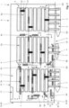
- a schematic view of a container terminal 1 is shown in plan view, which is designed as a port terminal.
- several ships 3 can dock at a quay 2 of a port in order to deliver containers or to pick up.
- gantry cranes 4 are provided on the quay 2 , which are also referred to as ship-to-shore cranes and whose booms extend over the ships 3 on the one hand and over the quay 2 on the other.
- the ships 3 can also be loaded or unloaded using what are known as harbor cranes, the jib of which is pivoted about a vertical axis above the corresponding ship 3 .
- Both the gantry cranes 4 and the port cranes represent so-called handling equipment.
- the container terminal 1 is surrounded by a boundary 10 and is thereby separated from its external surroundings and from public traffic outside the container terminal 1.
- the container terminal includes within the boundary 10 a container store 5, in which containers can be stacked for short-term interim storage in at least one storage area 5a, also referred to as a stack, after they have been unloaded from the ships 3 and before they are transported to a road or railway vehicle loaded or after they have been delivered therefrom and before they are loaded onto the ships 3.
- Several storage areas 5a and several storage aisles are preferably provided in order to space the at least one storage area 5a from the boundary 10 or, in the case of several storage areas 5a, two adjacent storage areas 5a from one another and from the boundary 10 of the container terminal.
- the storage aisles comprise longitudinal aisles L1 to Ln running essentially parallel to the edge of the quay 2 in the longitudinal direction L figure 1 nine longitudinal aisles L1 to L9, and transverse aisles Q1 to Qn running perpendicular to the quay 2 in the transverse direction Q, in figure 1 four cross aisles Q1 to Q4.
- the transverse aisles Q1 to Qn thus cross the longitudinal aisles L1 to Ln at right angles, but other angles between the storage aisles are also possible.
- the containers are aligned with their longitudinal side parallel to the longitudinal direction L.
- each storage area 5a several, for example ten, rows of containers can be parked with their long sides next to one another and six containers per row or more containers can be placed one above the other.
- At least one stacker crane 7 is provided for all of the adjacent storage areas 5a in the longitudinal direction L.
- Each stacker crane 7 is preferably designed as a gantry crane, which has one or two parallel crane girders 7a that are spaced apart from one another.
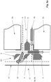
- the crane girders 7a extend in the transverse direction Q, span each row of the associated storage area 5a and protrude on both sides in the transverse direction Q beyond the associated storage area 5a above the adjacent longitudinal aisles, as a result of which they cover part of the respective longitudinal aisle and the lanes there in the top view (see Fig figure 3 ).
- the crane girder or girders 7a are supported by four vertical supports 7b (see figure 4 ) and together form the portal-shaped structure.
- the stacking crane 7 can be moved in the longitudinal direction L along the associated storage area 5a over the containers stacked therein and thus along the associated longitudinal aisles.
- a load handling device hanging down from the crane girder 7a can be moved past the supports 7b and between them.
- containers can be picked up or unloaded by the stacking crane 7 in both of the longitudinal aisles adjacent to the storage area 5a and located opposite one another.
- stacking cranes 7 also represent handling equipment and can be used, for example, as so-called automated stacking cranes (ASC for short), rubber-tired stacking cranes (Rubber-Tyred Gantry Crane - RTG for short) or rail-mounted stacking cranes (Rail-Mounted Gantry Crane - for short: RMG) trained.
- a stacking crane 7 can also manage several adjacent storage areas 5a in the longitudinal direction L, which are arranged one behind the other as seen in the longitudinal direction L and are each spaced apart from one another by a transverse aisle, and for this purpose travel over one or more transverse aisles.
- a stacking crane 7 can be assigned to each storage area 5a.
- a layout rotated by 90 degrees with respect to the quay 2 is also conceivable, in which the storage areas 5a and the longitudinal aisles in particular are not essentially parallel, but transverse and essentially perpendicular to the edge of the quay 2 extend. This applies in particular when the stacker cranes 7 are designed as ASCs.
- a joint and simultaneous operation of at least takes place for the transport of containers an internal automatically guided heavy-duty vehicle 8a and/or at least one internal manually-guided heavy-duty vehicle 8b and/or at least one external manually-guided heavy-duty vehicle 8c.
- safe mixed traffic of automatically guided and manually guided and/or mixed traffic of internal and external heavy-duty vehicles 8a, 8b, 8c is possible in the separate operating area B.
- the containers are transported between the container store 5 or its handling equipment and the handling equipment arranged on the quay 2 by means of the internal automatically or manually guided heavy-duty vehicles 8a, 8b.
- containers can be picked up from the container storage facility 5 or its stacking crane 7 for further transport by public transport, or can be delivered to the container storage facility 5 for interim storage after transport by public transport. These transports are carried out in a so-called horizontal transport.
- Both the handling equipment arranged on the quay 2 and in the container store 5 or the storage areas 5a can transfer containers and thus load and unload the heavy-duty vehicles 8a, 8b, 8c if they are located in the corresponding transfer areas below the boom or crane girder 7a of the respective handling equipment .
- the containers can be transferred directly between the respective heavy-duty vehicle 8a, 8b, 8c and the gantry crane 4 or between the heavy-duty vehicle 8a, 8b, 8c and the stacker crane 7 of the container storage facility 5. If the containers are transported horizontally with straddle carriers or heavy-duty vehicles 8a, 8b with a lifting platform, the containers can first be parked in the transfer area on the ground or in a container or transfer rack already parked there or picked up from it.
- the transfer areas thus each represent an interface between the horizontal traffic and a handling device.
- the internal heavy-duty vehicles 8a, 8b can be designed, for example, as container transport vehicles, terminal trucks or straddle carriers within the meaning of the above definition.
- the entire fleet of heavy-duty vehicles 8a, 8b in the container terminal 1 can only have one of the aforementioned vehicle types, ie, for example, only terminal trucks, or several various vehicle types, such as terminal trucks and straddle carriers.
- vehicle types are only intended and designed or approved for internal use, ie for internal operation within the container terminal 1 or in its separate operating area B, and not for external use in public transport.
- Such heavy-duty vehicles 8a, 8b can be moved freely on the quay 2 via wheels and are therefore bound to the floor, but not to rails.
- the heavy-duty vehicles 8a, 8b are to be distinguished from rail vehicles and in particular from railway wagons.
- the wheels of the heavy-duty vehicles 8a, 8b are each provided with tires which are preferably air-filled rubber tires in the sense of tires.
- the heavy-duty vehicles 8a, 8b each have a travel drive with a motor designed, for example, as an electric motor or an internal combustion engine, and a transmission in order to drive the wheels via this.
- the external heavy-duty vehicles 8c are usually in the form of conventional trucks that are approved for use on public roads.
- the separate operating area B is located within the boundary 10 and is thereby also separated from public traffic outside of the container terminal 1 .
- the boundary 10 can extend to the edge of the quay 2 and be designed, for example, as a fence or wall.
- the boundary 10 is interrupted at one or more points in order to form one or more external passage areas 11 there for the external, manually guided heavy-duty vehicles 8c.
- the heavy-duty vehicles 8c coming from public transport outside of the container terminal 1 can only enter the container terminal 1 through the passage areas 11 and herewith (see figure 1 ) or only afterwards (see figure 3 ) drive through another external passage area 11a into the operating area B or from there back out of the operating area B and into public transport.
- a security lock for logging in and out including an identification of the heavy-duty vehicles 8c entering and exiting and their drivers, can also be provided.
- the internal heavy-duty vehicles 8a, 8b are not allowed to drive through the passage areas 11, 11a, since they are not allowed to enter the public traffic outside of container terminal 1 and are also not allowed to leave operational area B.
- the automatically guided heavy-duty vehicles 8a can only be operated as intended within the operating area B anyway. An exception to this is leaving operating area B, for example for maintenance or repair purposes. In this case, however, the heavy-duty vehicles 8a do not leave the operating area B automatically, so that this does not count as normal operation.
- the internal and/or external manually guided heavy-duty vehicles 8b, 8c can also be operated in the separate operating area B in addition to the internal automatically guided heavy-duty vehicles 8a together or simultaneously with them.
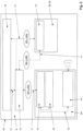
- the figure 2 shows a schematic functional representation of a system for realizing a mixed traffic of manually and automatically guided heavy-duty vehicles 8a, 8b, 8c in the separate operating area B.
- the separate operating area B of the container terminal 1 can be seen.
- a fleet control system 12 is a modular functional module of the system for mixed traffic provided, via which the simultaneous traffic of the internal and external or automatically and manually guided heavy-duty vehicles 8a, 8b, 8c is coordinated in the separate operating area B and in particular in the storage aisles. As part of this, the exchange of various operating information described below takes place and, in particular, route planning and route monitoring are carried out.
- wireless communication connections 17 in the sense of data connections, for example in the form of W-LAN connections for the exchange of operating information, can be established between the heavy-duty vehicles 8a, 8b, 8c and the fleet control system 12.
- the fleet control system 12 continuously processes the positions of all heavy-duty vehicles 8a, 8b, 8c located in the operating area B, which can change over time.
- the fleet control system 12 therefore knows essential operating information on the status, in particular the position of each heavy-duty vehicle 8a, 8b, 8c in the corresponding warehouse aisle or the driving areas, lanes and directions of travel used in each case.
- the fleet control system 12 can dynamically block or release areas, in particular individual storage aisles or lanes, for all heavy-duty vehicles 8a, 8b, 8c located in the operating area B in the sense of restricted areas and thus ensure that only one heavy-duty vehicle 8a, 8b, 8c is located.
- the fleet control system 12 can manage or coordinate the entry and exit of the heavy-duty vehicles 8a, 8b, 8c in the above-mentioned transfer areas as well as maintenance orders and, in the case of battery-operated heavy-duty vehicles 8a, 8b, any necessary battery replacement orders or battery charging orders.
- the fleet control system 12 can also carry out what is known as deadlock monitoring of the automatically guided heavy-duty vehicles 8a.
- the manually operated heavy-duty vehicles 8b, 8c are provided with a further modular function module in the form of a driver information system 13, which is also referred to as an on-board unit. It can be provided that manually guided heavy-duty vehicles 8b, 8c may only enter the separate operating area B together with such a driver information system 13. Only then can each manual heavy-duty vehicle 8b, 8c be included and taken into account in the coordination of the mixed traffic. This increases the productivity and also the safety of the container terminal 1 since traffic jams can be avoided or at least minimized.
- the driver information system 13 communicates with the fleet control system 12 via one of the wireless communication links 17 in order to exchange operating information.
- the fleet control system 12 transmits operating information to the driver of the respective heavy goods vehicle 8b, 8c via the driver information system 13, in particular in the form of instructions for manual driving of the heavy goods vehicle 8b, 8c.
- Instructions can contain the specifications of a route to the destination already explained above and changes thereto, preferably including storage aisles to be used, lanes, directions of travel, restricted areas currently set up, driving speeds and traffic rules.
- Driver information system 13 also determines possible ones deviations from the instructions and informs or warns the driver about this visually and/or acoustically.
- the driver information system 13 determines the position of the heavy-duty vehicle 8b, 8c, preferably continuously and for example by means of a GPS unit, and also reports this back to the fleet management system 12. Information about the operating situation in operating area B can also be provided via driver information system 13 .
- the driver information system 13 can be designed as a mobile device, which is preferably arranged on each manually operated heavy-duty vehicle 8b, 8c at the latest before it enters the operating area B and is carried within the operating area B by the heavy-duty vehicle 8b, 8c.
- the driver information system 13 can be handed over to the driver upon entry into the container terminal 1 in the passage area 11 or 11a and handed over again upon exit.
- Appropriate mobile devices are used in particular for external, manually guided heavy-duty vehicles 8c such as conventional trucks.
- the driver information system 13 can also be in the form of a mobile device or can be permanently installed on the heavy-duty vehicle 8b.
- the automatically guided heavy-duty vehicles 8a are each provided with a further modular function module in the form of a device for automatic navigation 14 within the operating area B.
- the heavy-duty vehicles 8a can use this to navigate in a computer-assisted manner on the basis of the routes specified by the fleet system 12 and to be guided automatically.
- each automatically guided heavy-duty vehicle 8a is provided with a further modular functional module in the form of a device for determining the position 15. Transponder technology is preferably used here.
- the devices for position determination 15 have at least one antenna, via which transponders embedded in predetermined locations in the floor of the operating area B can be detected and the position and orientation of the heavy-duty vehicle 8a can be determined via this.
- Other methods for Determining the position and orientation can of course be used, for example D-GPS/LPR.
- the determined positions and orientations can also be transmitted to the device for automatic navigation 14 via a corresponding data line 19 and can thus be taken into account in the form of a target/actual comparison during automatic guidance along the specified and possibly changed routes.
- sensory object detection can take place and be taken into account for monitoring the route.
- the automatically guided heavy-duty vehicles 8a are each provided with a sensor for object recognition 16 as a further modular function module, which is operatively connected to the vehicle control via the data line 19 and the device for automatic navigation 14 or the device for determining position 15. If an obstacle is detected on or at a predetermined distance next to the lane, the vehicle control system intervenes in order to prevent a collision.
- the heavy-duty vehicle 8a can brake automatically and/or drive around the detected obstacle in an automatically guided manner.
- the obstacle can also be another heavy goods vehicle 8a, 8b, 8c that is driving ahead or is approaching an intersection where a collision is imminent (see Fig Figure 5a ).
- the fleet control system 12 coordinates the different types of traffic in such a way that, as a rule, internal and external or automatically and manually guided heavy-duty vehicles 8a, 8b, 8c cannot enter the intersection areas and meet one another at the same time.
- intervention in the crossing areas by means of object recognition 16 only has to be carried out in exceptional cases.
- the fleet control system 12 can be integrated into a terminal control system 18 and thus be part of it or be connected to it for an exchange of operating information via a wireless or wired communication link 17 in order to be able to exchange operating information.
- Transport orders for the heavy-duty vehicles 8a, 8b are planned via the terminal control system 18 and transmitted to the fleet control system 12 via the communication link 17.
- the transport orders can then be managed by the fleet control system 12 and used for the coordination of the mixed traffic of automatically guided and manually guided heavy goods vehicles 8a, 8b, in particular the route planning and route monitoring that takes place here.
- the fleet management system 12 then generates routes from the transport orders and transmits them via the wireless communication links 17 to the heavy-duty vehicles 8a, 8b.
- the terminal control system 18 can also transmit transport orders directly via a further wireless communication connection 17, for example in the form of a W-LAN connection, to the manually operated heavy-duty vehicle 8b or its driver information system 13.
- the communication connection 17 with the fleet control system 12 can then also be used to coordinate the corresponding heavy-duty vehicles 8b in the mixed traffic on the basis of the transport orders, in that the fleet control system 12 gives the driver of the respective heavy-duty vehicle 8b appropriate instructions via the driver information system 13 for driving the heavy-duty vehicle manually 8b transmitted.
- the warehousing or administration of the container store 5 can also take place via the terminal control system 18 and can be included in the planning of the transport orders.
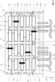
- the figure 3 shows another schematic view of the container terminal 1 in plan view.
- Six longitudinal aisles L1 to L6 and five transverse aisles Q1 to Q5 are shown, via which the storage areas 5a are spaced apart from one another and from the boundary 10 and the handling equipment arranged on the quay 2 .
- Each storage aisle includes at least one lane for the heavy-duty vehicles 8a, 8b, 8c.
- no heavy-duty vehicles 8a, 8b, 8c but the lanes provided for this are shown schematically as lines provided with arrows.
- Lanes reserved for internal heavy goods vehicles 8a, 8b are shown with dotted lines and lanes reserved for external heavy goods vehicles 8c with broken lines.
- the storage aisles are reserved in alternating order for certain of the heavy-duty vehicles 8a, 8b, 8c and that the corresponding other heavy-duty vehicles 8a, 8b, 8c may only cross in some crossing areas 20, 21 of two storage aisles.
- the lanes of corresponding heavy-duty vehicles 8a, 8b, 8c, which are otherwise separated by lane, are only provided together and with opposite directions of travel in the outer transverse lanes Q1 and Q5.
- the separate operating area B can also be at least partially bounded by further boundary elements 9 that do not coincide with the boundary 10 and further bound the operating area B in relation to the outer boundary 10.
- the other delimiting elements 9 of the operating area B can also be designed as a fence or wall.
- a delimiting element 9 is provided between the first two longitudinal aisles L1 and L2 and in the outer transverse aisles Q1, Q2, Q4 and Q5.
- the outermost delimiting elements 9 in the cross-aisles Q1 and Q5 serve as a barrier for the lanes used by the heavy-duty vehicles 8a and prevent them from leaving the operating area, but each form a passage area 11a for the heavy-duty vehicles 8c.
- the two inner delimiting elements 9 delimit the operating area B between the corresponding storage areas 5a in the transverse aisles Q2 and Q4.
- the storage areas 5a themselves also delimit the operating area B between the first two longitudinal aisles L1 and L2.
- Corresponding lanes with opposite directions of travel are provided for this purpose in cross aisle Q3.
- the separate operating area B can comprise a first area B1 in the sense of an internal area and an adjoining second area B2 in the sense of a mixed area (see also figures 1 and 4 ).
- Mixed traffic is not permitted in the internal first area B1, but only internal traffic.
- External manually guided heavy-duty vehicles 8c such as conventional trucks are excluded from this internal area B1, but are allowed to operate in the second area B2.
- further delimiting elements 9 can be provided analogously to the delimiting elements 9 mentioned above, each of which forms an internal passage area 11b with or without a security lock.
- the first area B1 is connected to the second area B2 via each passage area 11b, but only one Passage of internal heavy goods vehicles 8a, 8b is allowed.
- the delimiting elements 9 installed between the longitudinal aisles L5 and L6 in the transverse aisles Q1 and Q5 thus serve as a barrier for the lanes used by the heavy-duty vehicles 8c.
- the inner delimitation element 9 delimits the operating area B between the corresponding storage areas 5a in the cross aisle Q3.
- another passage area 11b is formed, through which only internal heavy-duty vehicles 8a, 8b, preferably only heavy-duty vehicles 8a, can drive into and out of the operating area B. Corresponding lanes with opposite directions of travel are provided for this purpose in the cross-aisles Q2 and Q4.
- heavy goods vehicles 8c and/or 8b can also be prevented from entering the first area B1 or heavy goods vehicles 8a and/or 8b from leaving the operating area B by using the routes specified by the fleet management system 12 run only outside of the first area B1, in particular only in the second area B2.
- the internal first area B1 can be defined by the fleet management system 12 as a restricted area and taken into account as such in the route planning and route monitoring and thus excluded for the heavy-duty vehicles 8c and/or 8b.
- the first area B1 can therefore also be operated as a purely automatic area in which only heavy-duty vehicles 8a are allowed to move.
- the internal first area B1 preferably extends on a water-side side of the container store 5 facing the quay 2 and includes the container gantry cranes 4 and at least the storage areas 5a immediately adjacent to the quay 2 and the longitudinal aisle L6.
- the second area B2 serving as a mixing area includes the remaining storage areas 5a of the container storage facility 5, so that both internal heavy-duty vehicles 8a, 8b and external heavy-duty vehicles 8c may operate in its storage aisles, taking into account the specifications described in more detail below. Only the external heavy-duty vehicles 8c are allowed to leave the operating area B and the container terminal 1 through the passage areas 11, 11a.
- the two transfer areas of the stacker crane 7 are also reserved for the corresponding traffic for each storage area 5a and associated stacker crane 7.
- the lanes are thus arranged laterally on the storage areas 5a and therefore border on the corresponding stacker crane 7 at least within the transfer areas.
- the stacking cranes 7, designed for example as so-called double cantilever RMGs can transfer containers on both sides, in particular longitudinal sides, of a storage area 5a in the adjacent storage aisles and thus optionally to an internal heavy-duty vehicle 8a, 8b, which may be automatically guided, or an external heavy-duty vehicle 8c or to record.
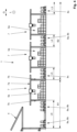
- FIG 4 shows a partial schematic view of the container terminal 1 in a side view.
- FIG 3 For the sake of clarity, no more than two lanes per storage aisle are shown as an example, more lanes can also be provided in the longitudinal aisles. this is in figure 4 shown as an example for the longitudinal lanes L5 and L4, each of which has three lanes.
- the middle lane represents a type of bypass lane which, unlike the other lanes, does not pass through the transfer area of the stacker cranes 7 below the crane girders 7a.
- the bypass lane can therefore be used to overtake heavy-duty vehicles 8a, 8b, 8c that are in the transfer area for loading or unloading.
- the longitudinal aisle 6 extending on the quay 2 comprises a total of four further lanes in addition to a lane leading through the transfer area of the associated stacker crane 7 , at least some of which are routed through the transfer area of the container gantries 4 .
- the reservation shown as an example provides for the storage aisles or the lanes running in them between the storage areas 5a to be used as follows: longitudinal aisles L1, L3, L5 for external heavy-duty vehicles 8c, longitudinal aisles L2, L4, L6 for internal heavy-duty vehicles 8a, 8b, transverse aisles Q1 and Q5 common for heavy-duty vehicles 8a, 8b, 8c with opposite directions of travel for internal and external traffic, cross-aisles Q2 and Q4 for internal heavy-duty vehicles 8a, 8c, cross-aisle Q3 for external heavy-duty vehicles 8c.
- a mixed traffic of automatically guided and manually guided respectively internal and external heavy-duty vehicles 8a, 8b, 8c comes with it as in figure 3 recognizable only in the second area B2 and there in particular in the outer cross streets Q1 and Q5 as well as in some, here every second, crossing areas of cross streets and longitudinal streets, but not within a longitudinal street between the crossing areas.
- the directions of travel are specified for the different types of traffic.
- the external heavy-duty vehicles 8c that they run in a kind of circulating operation around the storage areas 5a and in doing so in a clockwise direction and accordingly drive in and out of the operating area B in their lanes.
- the internal heavy-duty vehicles 8a, 8b run in the operating area B in a corresponding counterclockwise circulation mode. All lanes running through the longitudinal aisles L1 to L5 have the same direction of travel in the sense of one-way streets. Circulation operation with opposite directions of travel is only possible in the longitudinal aisle L6.
- the lanes to be driven in the individual warehouse aisles are specified.
- left-hand traffic can be prescribed for the internal heavy-duty vehicles 8a, 8b and right-hand traffic for the external heavy-duty vehicles.
- the points of contact between the different types of traffic are reduced to a minimum by the aforementioned specifications, which are also taken into account by the fleet control system 12 when specifying and changing routes described above.
- points of contact arise in crossing areas between the traffics in which the respective traffics take predetermined defined routes. Appropriate lane markings can be provided in the crossing areas to ensure that these routes are followed.
- the lanes are provided with guide elements 6 in the form of chicane-like installations, so that only the intended routes are possible (in figure 3 not shown for better clarity).
- the first crossing area 20 is intended purely as a crossing where no turning into the crossing warehouse aisle or lane is permitted.
- several guide elements 6 are installed in the crossing area 20, which extend upwards from the roadway and thus receive their chicane-like function, which guides heavy goods vehicles 8a, 8b, 8c entering the crossing area 20 in the desired lane and direction of travel forces (see cross-sectional view AA in Figure 5b ).
- the guide elements 6 are dimensioned and arranged relative to one another such that the storage aisles in the crossing area are specifically narrowed in such a way that turning is not possible, but instead the crossing storage aisle or lanes must be crossed for collision-free operation.
- a corresponding outer guide element 6 is provided here between the adjacent lanes of each storage aisle, which widens towards the storage area 5a as viewed in the direction of the crossing lane and thus narrows the adjacent lanes.
- further guiding elements 6 can also be installed in the corner areas of the storage areas 5a adjoining the crossing area 20, for example in the form of angles.
- a central guide element 6 which, together with the respectively adjacent outer guide elements 6, correspondingly narrows the lanes between the storage areas 5a. This forces all heavy-duty vehicles 8a, 8b, 8c entering the crossing area 20 to cross it without turning into an intersecting warehouse aisle or lane and thus to continue driving in the respective warehouse aisle.
- the second intersection area 21 shown is provided as a turning intersection, in particular in the form of a T-intersection provided at the end of the longitudinal lanes. There, for certain lanes and directions of travel, turning into a predetermined one of several crossing lanes of the crossing warehouse lane is possible and necessary.
- heavy-duty vehicles 8c exiting longitudinal aisle L3 can only turn clockwise in accordance with the planned circulating operation and only into the outer lane reserved for heavy-duty vehicles 8c in transverse aisle Q1 and further away from storage areas 5a.
- Guide elements 6 comparable to the guide elements 6 of the crossing area 20 are therefore installed in the crossing area 21 .
- the guide elements 6 are dimensioned here and arranged in relation to one another in such a way that the storage aisles in the crossing area 21 are specifically narrowed in such a way that, coming from the longitudinal aisle L3, it is not possible to turn into the inner lane of the transverse aisle Q1, but rather to cross it for collision-free operation lanes and only then turn into the outer lane.
- the arrangement of the guide elements 6 shown in the crossing area 21 only allows crossing the crossing longitudinal aisle L3. This also applies to heavy-duty vehicles 8c entering the crossing area 21 in the outer lane, which are not allowed to turn counterclockwise into the longitudinal lane L3. The same can apply to an analogous crossing area at the other end of the longitudinal aisle L3 with regard to driving into the longitudinal aisle L3 from the transverse aisle Q5.
- the crossing areas of the same traffic can also be designed analogously and in particular by using appropriate guide elements 6 as crossings (for example crossings between L4 and Q2 and L3 and Q3) or turning crossings (for example crossings between L4 and Q1, L2 and Q2 or L5 and Q3).
- appropriate guide elements 6 for example crossings between L4 and Q2 and L3 and Q3) or turning crossings (for example crossings between L4 and Q1, L2 and Q2 or L5 and Q3).
- delimiting elements 9, analogous to the guiding elements 6, take on the function of chicane-like installations and are accordingly arranged in the respective storage aisle as part of crossing areas in such a way that a desired lane is blocked in a targeted manner in order to prevent straight-ahead driving and turning to force into a given warehouse aisle and, if necessary, lane.
- straddle carrier-type straddle carriers are used, with which both the loading and unloading of containers in storage areas 5a of the container warehouse 5 and the transport between the Container storage 5 and the container bridges 4 can be done.
- heavy-duty forklifts of the type known as reach stackers can be used in particular as manually guided heavy-duty vehicles 8b or handling equipment. Both corresponding straddle carriers and heavy-duty forklifts usually have what is known as a spreader as a load handling device for receiving containers.
- Stacking cranes 7 can then be dispensed with, at least in some storage areas 5a of the container store 5 .
- the aforementioned modular functional modules can be used for all of the above-mentioned possible vehicle types of heavy-duty vehicles 8a, 8b, 8c, but also for handling equipment such as the cranes, straddle carriers and heavy-duty forklift trucks mentioned.
- the system according to the invention can also be used with corresponding heavy-duty vehicles 8a, 8b, 8c not only as described above in relation to a container terminal 1 designed as a port terminal.
- a corresponding separate operating area B is part of a RoRo terminal for so-called RoRo ships (abbreviation for roll on roll off ships, in which the containers are loaded onto the ship by means of corresponding heavy-duty vehicles or be driven down from it), logistics center or an industrial company, in which containers are delivered or picked up and both internal, automatically guided heavy-duty vehicles 8a and together with this internal and/or external manually guided heavy-duty vehicles 8b, 8c are to be used in a corresponding mixed traffic .
- containers in particular ISO containers
- other normalized or standardized load carriers such as swap bodies, in particular swap bodies or swap bodies, can also be transported and handled.
Claims (10)
- Système de transport de conteneurs à l'aide de véhicules lourds (8a, 8b, 8c), lequel système comporte au moins un véhicule à fort tonnage externe (8c) et au moins un véhicule à fort tonnage interne (8a, 8b), un entrepôt de conteneurs (5) pourvu de plusieurs zones d'entrepôt (5a) et de plusieurs allées d'entrepôt ainsi qu'une zone d'exploitation séparée (B) dans laquelle les véhicules à fort tonnage (8a, 8b, 8c) peuvent être utilisés, dans la zone d'exploitation séparée (B) au moins une première voie de circulation étant réservée à l'au moins un véhicule à fort tonnage externe (8c) et au moins une deuxième voie de circulation étant réservée à l'au moins un véhicule à fort tonnage interne (8a, 8b), les véhicules utilitaires à fort tonnage (8a, 8b, 8c) pouvant être utilisés conjointement en circulation mixte et les première et deuxième voies de circulation étant guidées chacune à travers une zone de transfert d'un dispositif de transbordement (7) d'une zone d'entrepôt (5a) et étant disposées chacune latéralement au niveau la zone d'entrepôt (5a), caractérisé en ce que les voies de circulation sont physiquement séparées les unes des autres au moins par portions par des éléments de guidage (6), les première et deuxième voies de circulation s'intersectant dans des premières zones d'intersection (20) de deux allées d'entrepôt (L1-Ln, Q1- Qn) où les éléments de guidage (6) sont disposés de manière à ce que les premières zones d'intersection (20) soient conçues comme de pures intersections de traversée, les première et deuxième voies de circulation s'intersectant dans des deuxièmes zones d'intersection (21) de deux allées d'entrepôt où les éléments de guidage (6) sont disposés de manière à ce que les deuxièmes zones d'intersection (21) soient conçues comme des intersections de changement de direction,plusieurs éléments de guidage (6) étant installés dans chaque première zone d'intersection (20), conçue comme pure intersection de traversée, lesquels éléments de guidage s'étendent de la chaussée vers le haut et sont ainsi dotés d'une fonction de type chicane qui contrait des véhicules à fort tonnage (8a, 8b, 8c), qui entrent dans la première zone d'intersection (20), dans la voie de circulation et le sens de circulation souhaités,les éléments de guidage (6) situés dans la première zone d'intersection (20) étant dimensionnés et disposés les uns par rapport aux autres de sorte que les allées d'entrepôt (L1-Ln, Q1- Qn) situées dans la première zone d'intersection (20) sont volontairement rétrécies de sorte qu'un changement de direction ne soit pas possible, mais une traversée de l'allée d'entrepôt (L1-Ln, Q1-Qn) ou des voies de circulation intersectantes doit être effectuée pour un fonctionnement sans collision,un changement de direction vers une voie de circulation spécifiée parmi plusieurs voies de circulation intersectantes de l'allée d'entrepôt intersectante (L1-Ln, Q1- Qn) étant possible et nécessaire pour des voies de circulation et des directions de circulation déterminées dans chaque deuxième zone de croisement (21) conçue comme un croisement de changement de direction, ce pour quoi des éléments de guidage (6) sont installés dans la deuxième zone de croisement (21).
- Système selon la revendication 1, caractérisé en ce que le véhicule à fort tonnage externe (8c) circule dans la zone d'exploitation (B) dans le sens horaire et le véhicule à fort tonnage interne (8a, 8b) circule dans la zone d'exploitation (B) dans le sens antihoraire ou vice-versa.
- Système selon l'une des revendications 1 ou 2, caractérisé en ce que le véhicule à fort tonnage externe (8c) et le véhicule à fort tonnage interne (8a, 8b) circulent dans le sens horaire ou antihoraire dans la zone d'exploitation (B).
- Système selon l'une des revendications 1 à 3, caractérisé en ce que le système comprend un système de direction de flotte (12) qui permet de coordonner la circulation mixte des véhicules à fort tonnage (8a, 8b, 8c) dans la zone d'exploitation séparée (B), notamment au moyen d'un traitement continu des positions des véhicules à fort tonnage (8a, 8b, 8c), de la spécification d'itinéraires des véhicules à fort tonnage (8a, 8b, 8c), du blocage de zones pour les véhicules à fort tonnage ( 8a, 8b, 8c).
- Système selon la revendication 4, caractérisé en ce que, dans la zone d'exploitation séparée (B), un véhicule à fort tonnage (8b, 8c) guidé manuellement est pourvu d'un système d'information de conducteur (13) et le système d'information de conducteur (13) est relié au système de direction de flotte (12) afin de donner des instructions à un conducteur du véhicule à fort tonnage (8b, 8c) pour conduire le véhicule à fort tonnage (8b, 8c) manuellement.
- Système selon la revendication 5, caractérisé en ce que le système d'information de conducteur (13) est conçu comme un dispositif mobile qui est disposé sur le véhicules à fort tonnage (8b, 8c) guidé manuellement avant qu'il n'entre dans la zone d'exploitation (B), de préférence remis au conducteur, et est emporté par le véhicule à fort tonnage (8b, 8c) à l'intérieur de la zone d'intervention (B).
- Système selon la revendication 6, caractérisé en ce que le système d'information de conducteur (13) est installé à demeure sur le véhicule à fort tonnage (8b, 8c) guidé manuellement.
- Système selon l'une des revendications précédentes, caractérisé en ce qu'un véhicule à fort tonnage (8a) guidé automatiquement, notamment sa commande de véhicule, est pourvu d'un dispositif de navigation automatique (14) et/ou d'un dispositif de détermination de position (15) et/ou d'un capteur de détection d'objet (16).
- Système selon l'une des revendications précédentes, caractérisé en ce qu'une liaison de communication sans fil (17) est prévue entre les véhicules à fort tonnage (8a, 8b, 8c) et le système de direction de flotte (12).
- Système selon l'une des revendications précédentes, caractérisé en ce que le système, notamment sa zone d'exploitation séparée (B), fait partie d'un terminal de conteneurs (1), de terminaux RoRo, d'un centre logistique ou d'une installation industrielle.
Applications Claiming Priority (2)
| Application Number | Priority Date | Filing Date | Title |
|---|---|---|---|
| DE102016111450.2A DE102016111450A1 (de) | 2016-06-22 | 2016-06-22 | System zum Transport von Containern, insbesondere ISO-Containern, mittels Schwerlastfahrzeugen |
| PCT/EP2017/065171 WO2017220629A1 (fr) | 2016-06-22 | 2017-06-21 | Système de transport de conteneurs, en particulier de conteneurs iso, au moyen de véhicules pour charges lourdes |
Publications (3)
| Publication Number | Publication Date |
|---|---|
| EP3475203A1 EP3475203A1 (fr) | 2019-05-01 |
| EP3475203C0 EP3475203C0 (fr) | 2023-06-07 |
| EP3475203B1 true EP3475203B1 (fr) | 2023-06-07 |
Family
ID=59152879
Family Applications (1)
| Application Number | Title | Priority Date | Filing Date |
|---|---|---|---|
| EP17732400.1A Active EP3475203B1 (fr) | 2016-06-22 | 2017-06-21 | Système de transport de conteneurs, en particulier de conteneurs iso, au moyen de véhicules pour charges lourdes |
Country Status (10)
| Country | Link |
|---|---|
| US (1) | US11524851B2 (fr) |
| EP (1) | EP3475203B1 (fr) |
| KR (1) | KR102366916B1 (fr) |
| CN (1) | CN109641707B (fr) |
| AU (1) | AU2017281300B2 (fr) |
| DE (1) | DE102016111450A1 (fr) |
| ES (1) | ES2949289T3 (fr) |
| MX (1) | MX2018016337A (fr) |
| SG (2) | SG11201811566TA (fr) |
| WO (1) | WO2017220629A1 (fr) |
Families Citing this family (7)
| Publication number | Priority date | Publication date | Assignee | Title |
|---|---|---|---|---|
| DE102016111447A1 (de) | 2016-06-22 | 2017-12-28 | Terex Mhps Gmbh | System zum Transport von Containern, insbesondere ISO-Containern, mittels Schwerlastfahrzeugen |
| US11377313B2 (en) * | 2017-06-14 | 2022-07-05 | The Richard C. Lydle Revocable Trust | Shipping container handling systems and methods |
| DE102017121496A1 (de) * | 2017-09-15 | 2019-03-21 | Konecranes Global Corporation | Verfahren zur Steuerung des Befahrens einer Übergabezone für Container von Transportfahrzeugen in einer Umschlaganlage für Container, Steuerungssystem hierfür und Umschlaganlage mit einem solchen Steuerungssystem |
| JP7064429B2 (ja) * | 2018-11-06 | 2022-05-10 | 株式会社東芝 | 情報処理装置、情報処理方法及びコンピュータプログラム |
| AT522891B1 (de) * | 2019-08-22 | 2021-03-15 | Tgw Logistics Group Gmbh | Transport- und Manipulationssystem und Verfahren zum Transport von Ladungsträgern |
| CN112109761A (zh) * | 2020-08-28 | 2020-12-22 | 中铁武汉勘察设计研究院有限公司 | 铁水联运码头前沿转向设备、系统以及方法 |
| CN113401234B (zh) * | 2021-06-11 | 2023-05-02 | 上海振华重工(集团)股份有限公司 | 一种自动驾驶车辆和人工驾驶车辆混行的方法及系统 |
Family Cites Families (40)
| Publication number | Priority date | Publication date | Assignee | Title |
|---|---|---|---|---|
| DE1708715A1 (de) | 1961-07-11 | 1971-07-08 | Weiss Karl Dipl Ing | Strassenkreuzung fuer unfallfreien Fliessverkehr |
| DE1459786A1 (de) | 1964-11-30 | 1971-10-14 | Weiss Karl Dipl Ing | Strassenkreuzung fuer unfallfreien Fliessverkehr |
| NL1005562C1 (nl) | 1997-03-18 | 1998-09-21 | Joannes Adrianus Van Dinten | Principe van de Spookrijders Beveiligingsconstructie. |
| JP2975594B1 (ja) * | 1998-07-31 | 1999-11-10 | 川崎重工業株式会社 | コンテナターミナルシステム |
| JP3056719B2 (ja) | 1998-10-23 | 2000-06-26 | 株式会社興研 | 自揚式移動設備据え付け撤去方法及び自揚式発電方法並びに自揚式移動設備 |
| US20020059075A1 (en) | 2000-05-01 | 2002-05-16 | Schick Louis A. | Method and system for managing a land-based vehicle |
| US20050060070A1 (en) | 2000-08-18 | 2005-03-17 | Nnt, Inc. | Wireless communication framework |
| US6321138B1 (en) * | 2000-09-15 | 2001-11-20 | Woodson Incorporated | Storage and retrieval system with automated order make up |
| US6974928B2 (en) | 2001-03-16 | 2005-12-13 | Breakthrough Logistics Corporation | Method and apparatus for efficient package delivery and storage |
| JP3794975B2 (ja) | 2002-04-01 | 2006-07-12 | 三菱重工業株式会社 | 荷役方法及び移載機並びに荷役システム |
| JP2003292168A (ja) | 2002-04-05 | 2003-10-15 | Mitsubishi Heavy Ind Ltd | コンテナターミナル及びコンテナターミナルにおける無人搬送台車の運用方法 |
| US9105003B2 (en) | 2003-01-10 | 2015-08-11 | Bearware, Inc. | Freight tracking and control system |
| PT1616822E (pt) * | 2004-07-06 | 2007-01-31 | Perpetuma | Um procedimento e um sistema para transferência de cargas |
| US7273172B2 (en) | 2004-07-14 | 2007-09-25 | United Parcel Service Of America, Inc. | Methods and systems for automating inventory and dispatch procedures at a staging area |
| US20060045659A1 (en) * | 2004-08-04 | 2006-03-02 | Hubbard William B Sr | Buffered magazine method and system for loading and unloading ships |
| US7987017B2 (en) | 2005-02-25 | 2011-07-26 | Apm Terminals North America, Inc. | System and process for improving container flow in a port facility |
| CN1769592A (zh) * | 2005-09-08 | 2006-05-10 | 大连理工大学 | 单向平面路网分流体系 |
| US7753637B2 (en) | 2007-03-01 | 2010-07-13 | Benedict Charles E | Port storage and distribution system for international shipping containers |
| JP5520448B2 (ja) | 2008-02-22 | 2014-06-11 | 三井造船株式会社 | コンテナ搬送トラックの運行管理システム |
| US7972102B2 (en) | 2008-07-24 | 2011-07-05 | Marine Terminals Corporation | Automated marine container terminal and system |
| EP2189572B1 (fr) | 2008-11-19 | 2016-04-13 | Vicente L. Simó Montaner | Système de gestion du trafic dans les rond-points urbains et interurbains |
| DE102008061198A1 (de) * | 2008-12-09 | 2010-06-10 | Gottwald Port Technology Gmbh | Verfahren und eine Anlage zum Umschlag von normierten Ladungssträgern, insbesondere ISO-Containern und Wechselaufbauten, zwischen Schiene und Straße |
| US8348585B2 (en) | 2010-02-02 | 2013-01-08 | Salmoiraghi S.P.A. | System and method for unloading and loading load-containing units from and onto railway trucks |
| DE102010009323A1 (de) * | 2010-02-25 | 2011-08-25 | Telejet Kommunikations GmbH, 61462 | Transportsystem mit Traktoren |
| US20110295423A1 (en) | 2010-05-27 | 2011-12-01 | Noel Wayne Anderson | Condition based keep-out for machines |
| DE102010060504A1 (de) | 2010-11-11 | 2012-05-16 | Gottwald Port Technology Gmbh | System für den Umschlag von Containern |
| SG192630A1 (en) | 2011-04-06 | 2013-09-30 | Gottwald Port Tech Gmbh | Straddle carrier device comprising electric drives |
| IL217594A0 (en) | 2012-01-17 | 2012-06-28 | Eran Ben Alexander | Terminal resources and traffic flow management |
| DE102012108768A1 (de) | 2012-09-18 | 2014-03-20 | Gottwald Port Technology Gmbh | Batterie-elektrischer Sattelzug für ISO-Containertransport |
| US9008961B2 (en) | 2012-11-30 | 2015-04-14 | Google Inc. | Determining and displaying auto drive lanes in an autonomous vehicle |
| CA2907452A1 (fr) | 2013-03-15 | 2014-09-18 | Peloton Technology Inc. | Systemes et procedes de circulation en peloton de vehicules |
| JP6014535B2 (ja) | 2013-03-29 | 2016-10-25 | 三井造船株式会社 | コンテナターミナル構内トレーラの作業管理システム |
| US11625664B2 (en) | 2013-08-15 | 2023-04-11 | Crc R&D, Llc | Apparatus and method for freight delivery and pick-up |
| CN103910200B (zh) * | 2014-02-11 | 2017-02-08 | 华电重工股份有限公司 | 一种岸边集装箱转运方法及转运系统 |
| JP6219768B2 (ja) * | 2014-03-31 | 2017-10-25 | 三井造船株式会社 | コンテナターミナル及び門型クレーン並びにコンテナターミナルの運用方法 |
| CN104192576B (zh) | 2014-08-19 | 2017-01-11 | 天津港(集团)有限公司 | 集装箱水平运输系统 |
| DE102016111447A1 (de) | 2016-06-22 | 2017-12-28 | Terex Mhps Gmbh | System zum Transport von Containern, insbesondere ISO-Containern, mittels Schwerlastfahrzeugen |
| DE102017103032A1 (de) | 2017-02-15 | 2018-08-16 | Konecranes Global Corporation | Stromtankstelle für ein containertransportfahrzeug, containertransportfahrzeug und system hiermit |
| DE102017103097A1 (de) | 2017-02-15 | 2018-08-16 | Konecranes Global Corporation | Automatisch geführtes Transportfahrzeug für Container und Verfahren zum Betreiben desselben sowie System mit einem automatisch geführten Transportfahrzeug |
| DE102017121496A1 (de) | 2017-09-15 | 2019-03-21 | Konecranes Global Corporation | Verfahren zur Steuerung des Befahrens einer Übergabezone für Container von Transportfahrzeugen in einer Umschlaganlage für Container, Steuerungssystem hierfür und Umschlaganlage mit einem solchen Steuerungssystem |
-
2016
- 2016-06-22 DE DE102016111450.2A patent/DE102016111450A1/de active Pending
-
2017
- 2017-06-21 SG SG11201811566TA patent/SG11201811566TA/en unknown
- 2017-06-21 EP EP17732400.1A patent/EP3475203B1/fr active Active
- 2017-06-21 MX MX2018016337A patent/MX2018016337A/es unknown
- 2017-06-21 AU AU2017281300A patent/AU2017281300B2/en active Active
- 2017-06-21 SG SG10201912698TA patent/SG10201912698TA/en unknown
- 2017-06-21 WO PCT/EP2017/065171 patent/WO2017220629A1/fr active Search and Examination
- 2017-06-21 KR KR1020197001916A patent/KR102366916B1/ko active IP Right Grant
- 2017-06-21 CN CN201780051153.0A patent/CN109641707B/zh active Active
- 2017-06-21 ES ES17732400T patent/ES2949289T3/es active Active
- 2017-06-21 US US16/312,783 patent/US11524851B2/en active Active
Also Published As
| Publication number | Publication date |
|---|---|
| EP3475203C0 (fr) | 2023-06-07 |
| AU2017281300B2 (en) | 2022-11-24 |
| KR20190021359A (ko) | 2019-03-05 |
| CN109641707B (zh) | 2021-02-19 |
| WO2017220629A1 (fr) | 2017-12-28 |
| US20200307924A1 (en) | 2020-10-01 |
| SG11201811566TA (en) | 2019-01-30 |
| KR102366916B1 (ko) | 2022-02-23 |
| CN109641707A (zh) | 2019-04-16 |
| EP3475203A1 (fr) | 2019-05-01 |
| DE102016111450A1 (de) | 2017-12-28 |
| MX2018016337A (es) | 2019-09-18 |
| SG10201912698TA (en) | 2020-02-27 |
| ES2949289T3 (es) | 2023-09-27 |
| US11524851B2 (en) | 2022-12-13 |
| AU2017281300A1 (en) | 2019-01-24 |
Similar Documents
| Publication | Publication Date | Title |
|---|---|---|
| EP3475202B1 (fr) | Système de transport de conteneurs au moyen de véhicule pour charges lourdes guidés automatiquement et manuellement | |
| EP3475203B1 (fr) | Système de transport de conteneurs, en particulier de conteneurs iso, au moyen de véhicules pour charges lourdes | |
| EP3583586B1 (fr) | Vehicule de transport a guidage automatique pour conteneurs et son procede de fonctionnement et systeme avec un vehicule de transport a guidage automatique | |
| EP3619586B1 (fr) | Procédé et système servant à faire fonctionner un véhicule de transport à pilotage automatique pour des conteneurs | |
| EP3681831B1 (fr) | Procédé de gestion du passage de conteneurs de véhicules de transport dans une zone de transfert dans une installation de transbordement de conteneurs, système de gestion afférent et installation de transbordement munie dudit système de gestion | |
| EP2641856B1 (fr) | Véhicule porte-conteneurs sur pneumatiques et reliés au sol, pouvant être utilisés sélectivement avec ou sans chauffeur | |
| EP3582994B1 (fr) | Station de charge électrique pour véhicule conteneur de transport, véhicule conteneur de transport et système | |
| WO2000071452A1 (fr) | Installation de transbordement pour marchandises de detail, notamment pour conteneurs iso | |
| EP3595995A1 (fr) | Installation de stockage pour conteneurs et procédé pour faire fonctionner un véhicule de transport dans une installation de stockage de ce type | |
| EP3634901B1 (fr) | Dispositif de levage de portique pour conteneurs guidé automatiquement et procédé de fonctionnement d'un tel dispositif de levage de portique | |
| WO2018073097A1 (fr) | Agencement d'un chariot cavalier et d'une rangée d'éléments de repérage espacés | |
| EP1272414B1 (fr) | Installation de transbordement dans un port maritime ou fluvial | |
| WO2010063585A1 (fr) | Procédé de transbordement de charge dans un dépôt de conteneurs, notamment de conteneurs normalisés | |
| EP3538470B1 (fr) | Système de radiolocalisation d'un véhicule de transport pour conteneurs | |
| EP4077169A1 (fr) | Procédé d'acheminement dynamique de trafic de moyens de transport externes dans un entrepôt à rayonnages hauts |
Legal Events
| Date | Code | Title | Description |
|---|---|---|---|
| STAA | Information on the status of an ep patent application or granted ep patent |
Free format text: STATUS: UNKNOWN |
|
| STAA | Information on the status of an ep patent application or granted ep patent |
Free format text: STATUS: THE INTERNATIONAL PUBLICATION HAS BEEN MADE |
|
| PUAI | Public reference made under article 153(3) epc to a published international application that has entered the european phase |
Free format text: ORIGINAL CODE: 0009012 |
|
| STAA | Information on the status of an ep patent application or granted ep patent |
Free format text: STATUS: REQUEST FOR EXAMINATION WAS MADE |
|
| STAA | Information on the status of an ep patent application or granted ep patent |
Free format text: STATUS: REQUEST FOR EXAMINATION WAS MADE |
|
| 17P | Request for examination filed |
Effective date: 20190111 |
|
| AK | Designated contracting states |
Kind code of ref document: A1 Designated state(s): AL AT BE BG CH CY CZ DE DK EE ES FI FR GB GR HR HU IE IS IT LI LT LU LV MC MK MT NL NO PL PT RO RS SE SI SK SM TR |
|
| AX | Request for extension of the european patent |
Extension state: BA ME |
|
| DAV | Request for validation of the european patent (deleted) | ||
| DAX | Request for extension of the european patent (deleted) | ||
| STAA | Information on the status of an ep patent application or granted ep patent |
Free format text: STATUS: EXAMINATION IS IN PROGRESS |
|
| 17Q | First examination report despatched |
Effective date: 20210422 |
|
| STAA | Information on the status of an ep patent application or granted ep patent |
Free format text: STATUS: EXAMINATION IS IN PROGRESS |
|
| GRAP | Despatch of communication of intention to grant a patent |
Free format text: ORIGINAL CODE: EPIDOSNIGR1 |
|
| STAA | Information on the status of an ep patent application or granted ep patent |
Free format text: STATUS: GRANT OF PATENT IS INTENDED |
|
| GRAJ | Information related to disapproval of communication of intention to grant by the applicant or resumption of examination proceedings by the epo deleted |
Free format text: ORIGINAL CODE: EPIDOSDIGR1 |
|
| STAA | Information on the status of an ep patent application or granted ep patent |
Free format text: STATUS: EXAMINATION IS IN PROGRESS |
|
| INTG | Intention to grant announced |
Effective date: 20220706 |
|
| INTC | Intention to grant announced (deleted) | ||
| GRAP | Despatch of communication of intention to grant a patent |
Free format text: ORIGINAL CODE: EPIDOSNIGR1 |
|
| STAA | Information on the status of an ep patent application or granted ep patent |
Free format text: STATUS: GRANT OF PATENT IS INTENDED |
|
| INTG | Intention to grant announced |
Effective date: 20220901 |
|
| GRAS | Grant fee paid |
Free format text: ORIGINAL CODE: EPIDOSNIGR3 |
|
| GRAA | (expected) grant |
Free format text: ORIGINAL CODE: 0009210 |
|
| STAA | Information on the status of an ep patent application or granted ep patent |
Free format text: STATUS: THE PATENT HAS BEEN GRANTED |
|
| AK | Designated contracting states |
Kind code of ref document: B1 Designated state(s): AL AT BE BG CH CY CZ DE DK EE ES FI FR GB GR HR HU IE IS IT LI LT LU LV MC MK MT NL NO PL PT RO RS SE SI SK SM TR |
|
| REG | Reference to a national code |
Ref country code: GB Ref legal event code: FG4D Free format text: NOT ENGLISH |
|
| REG | Reference to a national code |
Ref country code: CH Ref legal event code: EP Ref country code: AT Ref legal event code: REF Ref document number: 1574467 Country of ref document: AT Kind code of ref document: T Effective date: 20230615 Ref country code: DE Ref legal event code: R096 Ref document number: 502017014846 Country of ref document: DE |
|
| PGFP | Annual fee paid to national office [announced via postgrant information from national office to epo] |
Ref country code: IE Payment date: 20230620 Year of fee payment: 7 |
|
| U01 | Request for unitary effect filed |
Effective date: 20230629 |
|
| U07 | Unitary effect registered |
Designated state(s): AT BE BG DE DK EE FI FR IT LT LU LV MT NL PT SE SI Effective date: 20230724 |
|
| REG | Reference to a national code |
Ref country code: LT Ref legal event code: MG9D |
|
| REG | Reference to a national code |
Ref country code: ES Ref legal event code: FG2A Ref document number: 2949289 Country of ref document: ES Kind code of ref document: T3 Effective date: 20230927 |
|
| U20 | Renewal fee paid [unitary effect] |
Year of fee payment: 7 Effective date: 20230914 |
|
| PG25 | Lapsed in a contracting state [announced via postgrant information from national office to epo] |
Ref country code: NO Free format text: LAPSE BECAUSE OF FAILURE TO SUBMIT A TRANSLATION OF THE DESCRIPTION OR TO PAY THE FEE WITHIN THE PRESCRIBED TIME-LIMIT Effective date: 20230907 |
|
| PGFP | Annual fee paid to national office [announced via postgrant information from national office to epo] |
Ref country code: GB Payment date: 20230721 Year of fee payment: 7 Ref country code: ES Payment date: 20230830 Year of fee payment: 7 |
|
| PG25 | Lapsed in a contracting state [announced via postgrant information from national office to epo] |
Ref country code: RS Free format text: LAPSE BECAUSE OF FAILURE TO SUBMIT A TRANSLATION OF THE DESCRIPTION OR TO PAY THE FEE WITHIN THE PRESCRIBED TIME-LIMIT Effective date: 20230607 Ref country code: HR Free format text: LAPSE BECAUSE OF FAILURE TO SUBMIT A TRANSLATION OF THE DESCRIPTION OR TO PAY THE FEE WITHIN THE PRESCRIBED TIME-LIMIT Effective date: 20230607 Ref country code: GR Free format text: LAPSE BECAUSE OF FAILURE TO SUBMIT A TRANSLATION OF THE DESCRIPTION OR TO PAY THE FEE WITHIN THE PRESCRIBED TIME-LIMIT Effective date: 20230908 |
|
| PG25 | Lapsed in a contracting state [announced via postgrant information from national office to epo] |
Ref country code: SK Free format text: LAPSE BECAUSE OF FAILURE TO SUBMIT A TRANSLATION OF THE DESCRIPTION OR TO PAY THE FEE WITHIN THE PRESCRIBED TIME-LIMIT Effective date: 20230607 |
|
| PG25 | Lapsed in a contracting state [announced via postgrant information from national office to epo] |
Ref country code: IS Free format text: LAPSE BECAUSE OF FAILURE TO SUBMIT A TRANSLATION OF THE DESCRIPTION OR TO PAY THE FEE WITHIN THE PRESCRIBED TIME-LIMIT Effective date: 20231007 |
|
| PG25 | Lapsed in a contracting state [announced via postgrant information from national office to epo] |
Ref country code: SM Free format text: LAPSE BECAUSE OF FAILURE TO SUBMIT A TRANSLATION OF THE DESCRIPTION OR TO PAY THE FEE WITHIN THE PRESCRIBED TIME-LIMIT Effective date: 20230607 Ref country code: SK Free format text: LAPSE BECAUSE OF FAILURE TO SUBMIT A TRANSLATION OF THE DESCRIPTION OR TO PAY THE FEE WITHIN THE PRESCRIBED TIME-LIMIT Effective date: 20230607 Ref country code: RO Free format text: LAPSE BECAUSE OF FAILURE TO SUBMIT A TRANSLATION OF THE DESCRIPTION OR TO PAY THE FEE WITHIN THE PRESCRIBED TIME-LIMIT Effective date: 20230607 Ref country code: IS Free format text: LAPSE BECAUSE OF FAILURE TO SUBMIT A TRANSLATION OF THE DESCRIPTION OR TO PAY THE FEE WITHIN THE PRESCRIBED TIME-LIMIT Effective date: 20231007 Ref country code: CZ Free format text: LAPSE BECAUSE OF FAILURE TO SUBMIT A TRANSLATION OF THE DESCRIPTION OR TO PAY THE FEE WITHIN THE PRESCRIBED TIME-LIMIT Effective date: 20230607 |
|
| REG | Reference to a national code |
Ref country code: CH Ref legal event code: PL |
|
| PG25 | Lapsed in a contracting state [announced via postgrant information from national office to epo] |
Ref country code: PL Free format text: LAPSE BECAUSE OF FAILURE TO SUBMIT A TRANSLATION OF THE DESCRIPTION OR TO PAY THE FEE WITHIN THE PRESCRIBED TIME-LIMIT Effective date: 20230607 |
|
| PG25 | Lapsed in a contracting state [announced via postgrant information from national office to epo] |
Ref country code: MC Free format text: LAPSE BECAUSE OF FAILURE TO SUBMIT A TRANSLATION OF THE DESCRIPTION OR TO PAY THE FEE WITHIN THE PRESCRIBED TIME-LIMIT Effective date: 20230607 |
|
| PG25 | Lapsed in a contracting state [announced via postgrant information from national office to epo] |
Ref country code: MC Free format text: LAPSE BECAUSE OF FAILURE TO SUBMIT A TRANSLATION OF THE DESCRIPTION OR TO PAY THE FEE WITHIN THE PRESCRIBED TIME-LIMIT Effective date: 20230607 |