EP3473918A1 - Beleuchtungsvorrichtung für einen kraftfahrzeugscheinwerfer - Google Patents
Beleuchtungsvorrichtung für einen kraftfahrzeugscheinwerfer Download PDFInfo
- Publication number
- EP3473918A1 EP3473918A1 EP17197220.1A EP17197220A EP3473918A1 EP 3473918 A1 EP3473918 A1 EP 3473918A1 EP 17197220 A EP17197220 A EP 17197220A EP 3473918 A1 EP3473918 A1 EP 3473918A1
- Authority
- EP
- European Patent Office
- Prior art keywords
- light
- optic element
- reflector
- primary
- primary optic
- Prior art date
- Legal status (The legal status is an assumption and is not a legal conclusion. Google has not performed a legal analysis and makes no representation as to the accuracy of the status listed.)
- Granted
Links
Images



Classifications
-
- B—PERFORMING OPERATIONS; TRANSPORTING
- B60—VEHICLES IN GENERAL
- B60Q—ARRANGEMENT OF SIGNALLING OR LIGHTING DEVICES, THE MOUNTING OR SUPPORTING THEREOF OR CIRCUITS THEREFOR, FOR VEHICLES IN GENERAL
- B60Q1/00—Arrangement of optical signalling or lighting devices, the mounting or supporting thereof or circuits therefor
- B60Q1/0011—Arrangement of optical signalling or lighting devices, the mounting or supporting thereof or circuits therefor with light guides for distributing the light between several lighting or signalling devices
-
- F—MECHANICAL ENGINEERING; LIGHTING; HEATING; WEAPONS; BLASTING
- F21—LIGHTING
- F21S—NON-PORTABLE LIGHTING DEVICES; SYSTEMS THEREOF; VEHICLE LIGHTING DEVICES SPECIALLY ADAPTED FOR VEHICLE EXTERIORS
- F21S41/00—Illuminating devices specially adapted for vehicle exteriors, e.g. headlamps
- F21S41/20—Illuminating devices specially adapted for vehicle exteriors, e.g. headlamps characterised by refractors, transparent cover plates, light guides or filters
- F21S41/25—Projection lenses
- F21S41/27—Thick lenses
-
- B—PERFORMING OPERATIONS; TRANSPORTING
- B60—VEHICLES IN GENERAL
- B60Q—ARRANGEMENT OF SIGNALLING OR LIGHTING DEVICES, THE MOUNTING OR SUPPORTING THEREOF OR CIRCUITS THEREFOR, FOR VEHICLES IN GENERAL
- B60Q1/00—Arrangement of optical signalling or lighting devices, the mounting or supporting thereof or circuits therefor
- B60Q1/02—Arrangement of optical signalling or lighting devices, the mounting or supporting thereof or circuits therefor the devices being primarily intended to illuminate the way ahead or to illuminate other areas of way or environments
- B60Q1/04—Arrangement of optical signalling or lighting devices, the mounting or supporting thereof or circuits therefor the devices being primarily intended to illuminate the way ahead or to illuminate other areas of way or environments the devices being headlights
-
- F—MECHANICAL ENGINEERING; LIGHTING; HEATING; WEAPONS; BLASTING
- F21—LIGHTING
- F21S—NON-PORTABLE LIGHTING DEVICES; SYSTEMS THEREOF; VEHICLE LIGHTING DEVICES SPECIALLY ADAPTED FOR VEHICLE EXTERIORS
- F21S41/00—Illuminating devices specially adapted for vehicle exteriors, e.g. headlamps
- F21S41/10—Illuminating devices specially adapted for vehicle exteriors, e.g. headlamps characterised by the light source
- F21S41/14—Illuminating devices specially adapted for vehicle exteriors, e.g. headlamps characterised by the light source characterised by the type of light source
- F21S41/141—Light emitting diodes [LED]
-
- F—MECHANICAL ENGINEERING; LIGHTING; HEATING; WEAPONS; BLASTING
- F21—LIGHTING
- F21S—NON-PORTABLE LIGHTING DEVICES; SYSTEMS THEREOF; VEHICLE LIGHTING DEVICES SPECIALLY ADAPTED FOR VEHICLE EXTERIORS
- F21S41/00—Illuminating devices specially adapted for vehicle exteriors, e.g. headlamps
- F21S41/20—Illuminating devices specially adapted for vehicle exteriors, e.g. headlamps characterised by refractors, transparent cover plates, light guides or filters
- F21S41/24—Light guides
-
- F—MECHANICAL ENGINEERING; LIGHTING; HEATING; WEAPONS; BLASTING
- F21—LIGHTING
- F21S—NON-PORTABLE LIGHTING DEVICES; SYSTEMS THEREOF; VEHICLE LIGHTING DEVICES SPECIALLY ADAPTED FOR VEHICLE EXTERIORS
- F21S41/00—Illuminating devices specially adapted for vehicle exteriors, e.g. headlamps
- F21S41/30—Illuminating devices specially adapted for vehicle exteriors, e.g. headlamps characterised by reflectors
- F21S41/32—Optical layout thereof
-
- F—MECHANICAL ENGINEERING; LIGHTING; HEATING; WEAPONS; BLASTING
- F21—LIGHTING
- F21S—NON-PORTABLE LIGHTING DEVICES; SYSTEMS THEREOF; VEHICLE LIGHTING DEVICES SPECIALLY ADAPTED FOR VEHICLE EXTERIORS
- F21S41/00—Illuminating devices specially adapted for vehicle exteriors, e.g. headlamps
- F21S41/30—Illuminating devices specially adapted for vehicle exteriors, e.g. headlamps characterised by reflectors
- F21S41/32—Optical layout thereof
- F21S41/322—Optical layout thereof the reflector using total internal reflection
-
- F—MECHANICAL ENGINEERING; LIGHTING; HEATING; WEAPONS; BLASTING
- F21—LIGHTING
- F21S—NON-PORTABLE LIGHTING DEVICES; SYSTEMS THEREOF; VEHICLE LIGHTING DEVICES SPECIALLY ADAPTED FOR VEHICLE EXTERIORS
- F21S41/00—Illuminating devices specially adapted for vehicle exteriors, e.g. headlamps
- F21S41/30—Illuminating devices specially adapted for vehicle exteriors, e.g. headlamps characterised by reflectors
- F21S41/32—Optical layout thereof
- F21S41/36—Combinations of two or more separate reflectors
- F21S41/365—Combinations of two or more separate reflectors successively reflecting the light
-
- G—PHYSICS
- G02—OPTICS
- G02B—OPTICAL ELEMENTS, SYSTEMS OR APPARATUS
- G02B19/00—Condensers, e.g. light collectors or similar non-imaging optics
- G02B19/0004—Condensers, e.g. light collectors or similar non-imaging optics characterised by the optical means employed
- G02B19/0028—Condensers, e.g. light collectors or similar non-imaging optics characterised by the optical means employed refractive and reflective surfaces, e.g. non-imaging catadioptric systems
-
- G—PHYSICS
- G02—OPTICS
- G02B—OPTICAL ELEMENTS, SYSTEMS OR APPARATUS
- G02B19/00—Condensers, e.g. light collectors or similar non-imaging optics
- G02B19/0033—Condensers, e.g. light collectors or similar non-imaging optics characterised by the use
- G02B19/0047—Condensers, e.g. light collectors or similar non-imaging optics characterised by the use for use with a light source
- G02B19/0061—Condensers, e.g. light collectors or similar non-imaging optics characterised by the use for use with a light source the light source comprising a LED
- G02B19/0066—Condensers, e.g. light collectors or similar non-imaging optics characterised by the use for use with a light source the light source comprising a LED in the form of an LED array
-
- G—PHYSICS
- G02—OPTICS
- G02B—OPTICAL ELEMENTS, SYSTEMS OR APPARATUS
- G02B6/00—Light guides; Structural details of arrangements comprising light guides and other optical elements, e.g. couplings
- G02B6/0001—Light guides; Structural details of arrangements comprising light guides and other optical elements, e.g. couplings specially adapted for lighting devices or systems
- G02B6/0011—Light guides; Structural details of arrangements comprising light guides and other optical elements, e.g. couplings specially adapted for lighting devices or systems the light guides being planar or of plate-like form
- G02B6/0033—Means for improving the coupling-out of light from the light guide
- G02B6/0035—Means for improving the coupling-out of light from the light guide provided on the surface of the light guide or in the bulk of it
- G02B6/0045—Means for improving the coupling-out of light from the light guide provided on the surface of the light guide or in the bulk of it by shaping at least a portion of the light guide
-
- G—PHYSICS
- G02—OPTICS
- G02B—OPTICAL ELEMENTS, SYSTEMS OR APPARATUS
- G02B6/00—Light guides; Structural details of arrangements comprising light guides and other optical elements, e.g. couplings
- G02B6/0001—Light guides; Structural details of arrangements comprising light guides and other optical elements, e.g. couplings specially adapted for lighting devices or systems
- G02B6/0011—Light guides; Structural details of arrangements comprising light guides and other optical elements, e.g. couplings specially adapted for lighting devices or systems the light guides being planar or of plate-like form
- G02B6/0033—Means for improving the coupling-out of light from the light guide
- G02B6/005—Means for improving the coupling-out of light from the light guide provided by one optical element, or plurality thereof, placed on the light output side of the light guide
- G02B6/0055—Reflecting element, sheet or layer
-
- F—MECHANICAL ENGINEERING; LIGHTING; HEATING; WEAPONS; BLASTING
- F21—LIGHTING
- F21Y—INDEXING SCHEME ASSOCIATED WITH SUBCLASSES F21K, F21L, F21S and F21V, RELATING TO THE FORM OR THE KIND OF THE LIGHT SOURCES OR OF THE COLOUR OF THE LIGHT EMITTED
- F21Y2115/00—Light-generating elements of semiconductor light sources
- F21Y2115/10—Light-emitting diodes [LED]
Definitions
- the invention relates to a lighting device for a motor vehicle headlight, comprising
- a light-conducting primary optic element arranged in the main emission direction of a first luminous means, a light input surface for coupling light rays into the primary optic element, a light output surface facing away from the first light source and a lateral surface extending between the light input surface and the light output surface has, at which the coupled-in light can be forwarded by total reflection in the direction of the light outcoupling surface of the primary optics element,
- a secondary optic element arranged in the light emission direction downstream of the light outcoupling surface of the primary optic element and having a light coupling surface on a side facing the light outcoupling surface of the primary optic element and a light coupling surface on a side remote from the primary optic element, and
- a reflector arranged in the light emission direction downstream of the light outcoupling surface of the secondary optics element and intended to generate a light distribution or a partial light distribution of a light function.
- the invention also relates to a motor vehicle headlight with at least one of the above-mentioned lighting device.
- a motor vehicle headlight can generate several lighting functions. These include, for example, a low beam function and a high beam function, these lighting functions must meet legal requirements.
- Such light functions are generally composed of a light distribution or a plurality of partial light distributions.
- LEDs are used, which are arranged on separate circuit boards due to the respective structures or lighting devices for generating the low beam function and the high beam light function.
- the secondary optics element is formed as part of a quadrilateral, wherein the secondary optics element is set up to direct or uninterruptedly pass the light beams emitted by the first illuminant which reach the light outcoupling surface of the secondary optics element during coupling out by means of refraction to let.
- the secondary optic element or the light outcoupling surface of the secondary optic element is convex, i. is arched outwards.
- a quadric In three dimensions, a quadric usually describes a surface in space, which is also called the second-order or quadratic surface.
- Examples of a three-dimensional quadric are a (bivalve) hyperboloid, ellipsoid, (hyperbolic) paraboloid, cylinder, elliptical paraboloid and a cone.
- quadrics typically have three-dimensional curved surfaces, with degenerate quadrics having rectilinear structures in some directions, such as a cylinder in the direction of its height or a cone, starting from a point of the base surface along the lateral surface toward the apex of the cone.
- the secondary optic element is formed as part of a ball having a ball center.
- the secondary optic element is designed as a cone.
- the secondary optic element is designed as part of an ellipsoid.
- the spherical surface, the conical surface and the partial surface of an ellipsoid generally have the desired advantages.
- the aim is to direct the light beams of a light source as directed or bundled on a provided for generating a light distribution or a part of a light distribution reflector or on the effective effective range of a reflector, without a decrease in the luminous flux.
- the light beams of the light source or of the light sources enter the primary optic element via the light coupling surface and are forwarded or deflected by the lateral surface of the primary optic element by total reflection onto the light output surface of the same or to the light coupling surface of a secondary optics element.
- the light output surface of the secondary optical element is followed by a reflector which reflects the light deflected by the first light source in a desired exit direction.
- the light output surface of the secondary optics element is in this case designed such that as far as possible all light rays are deflected by utilizing the law of refraction on the useful surface of the reflector.
- the light beams are refracted to different degrees.
- the secondary element located in the beam path which is formed, for example, as part of a sphere, a more homogeneous light exit cone is produced, i. that the light rays are refracted so that more light rays hit the reflector.
- the spherical shape favors a constant luminous flux and constant light intensity with slight changes in the spherical radius of the light coupling surface of the secondary optic element designed as a spherical surface. As a result, for example, the influence of the tolerances occurring during manufacture can be reduced.
- the conical surface as the light output surface of the secondary optical element causes an increase in the luminous flux at the reflector, in contrast to a conventional planar light output surface.
- the reflective outer surface of the primary optic element has a parabolically shaped region with a focal point, wherein the parabolically shaped region allows redirecting the light rays entering through the light coupling surface of the primary optic element in the direction of the light output surface of the primary optic element.
- the focal point of the parabolically shaped region of the primary optic element and the center of the sphere lie in one point.
- the secondary optic element formed as part of a sphere additionally acts as a compensating element in such an embodiment, for light rays which do not pass through the focal point of the parabolically shaped region when reflecting on the parabolically shaped region of the primary optic element, for example because of tolerances which inevitably occur be refracted from the spherical light output surface of the secondary optical element that these light beams are directed to the effective effective range of the reflector or at all to the reflector.
- the reflective outer surface of the primary optic element has a hyperbolic-shaped region with a real focal point and a virtual focal point, the hyperbolic-shaped region deflecting the light rays entering through the light coupling surface of the primary optic element in the direction of the light output surface of the primary optic element.
- the real focal point of the hyperbolic-shaped region of the primary optic element and the center of the sphere lie in one point.
- a front optic is arranged, which is configured to parallelize the light beams emitted by the first luminous means or to focus on a point.
- main emission direction is to be understood as the direction in which the first illuminant emits the strongest or most of the light as a result of its directivity.
- the attachment optics can also be designed as a TIR optics body.
- the attachment optics is set up to focus the light beams of the first illuminant onto the virtual focal point of the hyperbolic region of the primary optic element.
- the primary optic element and the secondary optic element are materially connected to one another, wherein preferably the primary optic element and the secondary optic element are formed in one piece and consist of the same material.
- Cohesive connections are all compounds in which the connection partners are held together by atomic or molecular forces. They are at the same time non-releasable compounds that can be separated only by destruction of the connecting means, such as soldering, welding, gluing, vulcanization.
- the attachment optics is materially connected to the primary optic element, wherein preferably the attachment optics is formed integrally with the primary optic element.
- the primary optic element and the secondary optic element are formed from Tarflon.
- Tarflon is a transparent, amorphous material, which has very good temperature and chemical resistance. Thus, Tarflon is heat resistant up to 135 ° C and has a high impact strength even at low temperatures. As a motor vehicle, especially a motor vehicle headlight, very low in winter and very in summer can be exposed to high temperatures, the above properties are of particular importance for a desired material.
- the first lighting means has at least one light source.
- the at least one light source is designed as an LED.
- the at least one light source is designed as a laser light source with a light conversion element.
- laser devices usually emit coherent, monochromatic light or light in a narrow wavelength range, but in a motor vehicle headlight generally for the emitted light white mixed light is preferred or legally prescribed, are in the emission of the laser device so-called light conversion elements for the conversion of substantially monochromatic Light is arranged in white or polychromatic light, where "white light” is understood as meaning light of such a spectral composition which causes the color impression "white” in humans.
- This light conversion element is embodied, for example, in the form of one or more photoluminescence converters or photoluminescent elements, with incident laser beams impinging on the light conversion element generally comprising photoluminescent dye and exciting this photoluminescent dye for photoluminescence, thereby emitting light in a wavelength different from the light of the irradiating laser device Wavelength ranges.
- the light output of the light conversion element has essentially characteristics of a Lambert's radiator.
- transmissive and transmissive refer to the blue portion of the converted white light.
- the main propagation direction of the blue light component after passing through the converter volume or conversion element is substantially rectified Propagation direction of the output laser beam.
- the laser beam is reflected or deflected at an interface attributable to the conversion element, so that the blue light component has a different propagation direction than the laser beam, which is generally designed as a blue laser beam.
- interference can be introduced as a passive safety sensor, such as surface structuring, steps or a hole, which prevent or reduce leakage of laser beams of a laser device in the event of a fault.
- a passive safety sensor such as surface structuring, steps or a hole, which prevent or reduce leakage of laser beams of a laser device in the event of a fault.
- the same area can also be used to place an active safety sensor.
- radiation traps which, as a laser-light-absorbing layer, bear against the reflection surface of the parabolic or hyperbolic-shaped region and transmit white mixed light and absorb laser light in the event of a malfunction or damage to the light conversion element.
- Another example of a laser safety concept are light sensors arranged in safety-relevant positions, which respectively compare light intensities of the light emitted by the laser device and light intensities of the light emitted by the light conversion element at these positions with stored reference intensities of the respective types of radiation measured in error-free operation, wherein if one is exceeded set, allowed deviation, the laser device is automatically turned off.
- the first light source is provided for generating a light distribution or a partial light distribution of a first light distribution, for example dipped beam or main beam.
- such a lighting device for generating the light function "dipped beam” can be used, wherein the lighting device in this light function "dipped beam” generates a light distribution which in a built-in state of the lighting device in a vehicle, in front of the vehicle produces a low-beam distribution according to the legal requirements.
- the lighting device in this light function "high beam” generates a light distribution which in a built-in state of the lighting device in a vehicle, in front of the vehicle a legal Requirements corresponding high beam distribution generated.
- the lighting device can also produce combinations of these light functions and / or generates only a partial light distribution, that is, for example, only a part of a distance, dimming, fog or daytime running light distribution.
- each LED can be controlled independently of the other LEDs.
- Each light-emitting diode can thus be switched on and off independently of the other LEDs of a light source, and preferably, when it comes to dimmable light-emitting diodes, are also dimmed independently of the other light-emitting diodes of the light source.
- the reflector is designed as a free-form reflector.
- a free-form reflector is a reflector whose special feature is that the reflector shape does not correspond to a mathematical rule surface. With the help of free-form reflectors, for example, an asymmetrical illumination can be realized without the otherwise necessary diffusing screen, at the same time increasing the usable light intensity.
- the reflector is designed as a parabolic reflector with a focal point, It can be provided that the focal point of the parabolic reflector and the ball center point lie in one point.
- Parallelized rays of the auxiliary optics must be incident parallel to the optical axis of the parabolic shaped region, to be deflected or deflected into the focal point of the parabolic shaped region.
- the reflector is designed as a hyperbolic reflector with a focal point.
- the focal point of the hyperbolic reflector and the center of the sphere lie in one point.
- a motor vehicle headlight comprises at least one lighting device.
- the motor vehicle headlamp is further provided a second light source for generating a light distribution or a partial light distribution of a second light function, such as low beam or high beam.
- the second lighting means may comprise at least one light source.
- the at least one light source is designed as an LED or as a laser light source with a light conversion element.
- first and the second lighting means are arranged on a common printed circuit board.
- the lighting means which are each provided for different light functions, for example, a low-beam function and a high beam function, and are independently controllable, arranged on a common circuit board.
- This procedure usually has a space-saving effect in a motor vehicle headlight, whereby now it must be ensured that both Light functions can be generated separately and / or together without mutual interference in front of the motor vehicle.
- a light-conducting primary optics element 100 arranged in the main radiation direction of a first luminous means 50 is shown, which on a side facing the first luminous means 50 has a light coupling surface 110 for coupling light into the primary optic element 100, a light coupling surface 120 and a side facing away from the first luminous means 50 has between the light input surface 110 and the light output surface 120 extending lateral surface on which the injected light can be forwarded by total reflection in the direction of the light outcoupling surface 120 of the primary optic element.
- main emission direction is to be understood as the direction in which the first illuminant radiates the strongest or most of the light as a result of its directivity.
- the reflective outer surface of the primary optic element 100 has a parabolically shaped region 150 with a focal point 151 , wherein the parabolically shaped region 150 makes it possible to redirect the light rays entering through the light coupling surface 110 of the primary optic element 100 in the direction of the light outcoupling surface 120 of the primary optic element 100 .
- a front optics 300 is arranged, which is adapted to parallelize or focus the light emitted from the first light source 50 light rays.
- the light beams of the first light source 50 are collimated or collimated by the attachment optics 300 and are directed onto the parabolic shaped region 150 of the primary optics element 100 such that the light rays after the reflection at the light source parabolically shaped area are bundled at the focal point 151 of the parabolic portion 150 150 or cut it.
- a secondary optics element 200 is arranged in the light emission direction downstream of the light outcoupling surface of the primary optics element 100 , wherein the secondary optics element 200 has a light input surface 210 on a side facing the light output surface 120 of the primary optics element 100 and a light output surface 220 on a side remote from the primary optics element 100 .
- the secondary optic element is in Fig. 1 formed as part of a ball with a ball center 201 , wherein the focal point 151 of the parabolic shaped portion 150 of the primary optic element 100 and the ball center point 201 lie in one point.
- Both the primary optic element 100 and the secondary optic element 200 are made of a material in the examples shown, wherein the material has a higher refractive index than the surrounding medium of the primary optic element 100 or of the secondary optic element 200, for example air.
- the primary optics element 100 and the secondary optical element 200 is integrally connected, wherein the primary optics element 100 and the secondary optical element 200 are preferably integrally formed, ie made of one piece and made of the same material, preferably Tarflon, meaning that the light output surface 120 of the primary optical element 100 and the light input surface 210 of the secondary optics element 200 lie in an imaginary plane.
- the attachment optics 300 is materially connected to the primary optic element 100 , wherein preferably the attachment optics 300 is formed integrally with the primary optic element 100 .
- a parabolically shaped reflector 400 having a focal point 401 is arranged downstream of the light outcoupling surface 220 of the secondary optical element 200 in the light emission direction , with the focal point 401 of the reflector 400 and the spherical center 201 lying at one point, ie the center of the sphere 201, the focal point 151 of FIG parabolic shaped region 150 of the primary optic element 100 and the focal point 401 of the parabolic reflector 400 coincide in one point.
- the reflector generates a light distribution or a partial light distribution of a light function, for example a low beam function or low beam distribution or a high beam function or a high beam distribution.
- the lighting device is installed in a motor vehicle headlight or as a motor vehicle headlight in a motor vehicle, wherein the lighting device generates or images the aforementioned light functions or light distributions in front of the motor vehicle, in particular in the direction of travel of the motor vehicle.
- direction of travel in this context refers to the direction in which a driven motor vehicle moves as intended. A technically possible reversing is not defined in this context as the direction of travel.
- the lighting device can also produce combinations of these light functions or light distributions and / or generates only a partial light distribution, for example only a part of a high beam or low beam function or distribution.
- the illumination device does not comprise any optical lenses.
- exemplary beam paths are to be seen, which experience no deflections through the partially spherical secondary optics element 200 , since the beam paths shown pass through the focal point 151 of the parabolic shaped region 150 and thus also the ball center 201 .
- Fig. 2 is another exemplary embodiment to see, in contrast to the example of Fig. 1 the reflective outer surface of the primary optic element 100 has a hyperbolic-shaped region 160 with a focal point 161 and a virtual focal point 162 .
- the hyperbolic-shaped region 160 makes it possible to redirect the light rays entering through the light coupling-in surface 110 of the primary optics element 100 in the direction of the light coupling-out surface 120 of the primary optics element 100.
- focal point 161 of the hyperbolic-shaped region 160 of the primary optic element 100 and the spherical center 201 of the secondary optic element 200 lie in one point. Further, the focal point 401 of the parabolic reflector 400 is also in Fig. 2 and the ball center 201 in one point.
- attachment optics 300 is different from the example Fig. 1 adapted to focus the light rays of the first light source 50 in the virtual focus 162 of the hyperbolic shaped region 160 of the primary optic element 100 , the light rays after reflection at the hyperbolic shaped region 160 in the focal point 161 of the hyperbolic shaped region 160 be bundled or cut this.
- Fig. 3 shows the example Fig. 1 in which, instead of the parabolic reflector 400, a hyperbolic reflector 410 having a focal point 411 is arranged.
- Fig. 4 shows the example Fig. 2 in which, instead of the parabolic reflector 400, a hyperbolic reflector 410 having a focal point 411 is arranged.
- a primary optics element 100 having a light coupling-in surface 110 and a planar light-emitting surface 120 as well as a reflector arranged in the light-emitting direction after the light coupling-out surface 120 of the primary optics element 100 are shown.
- a secondary optical element 200 missing in Fig. 5 a secondary optical element 200.
- a possible beam path is shown, it being shown that light rays are refracted at the transition from the primary optic 100 in the surrounding medium with a lower refractive index according to the law of refraction on the planar Lichtauskoppel constitutional 120 of the primary optics 100 , that these from the solder, which also in the Fig. 5 is shown can be broken away and thereby less light rays can be incident on a dependent of the particular reflector used, effective area of the corresponding reflector.
- Fig. 6 shows essentially the exemplary embodiments of the preceding figures, wherein with the in Fig. 6 illustrated exemplary beam path is to be illustrated how light rays are refracted at the transition from the secondary element 200 into the surrounding medium with a lower refractive index at the light output surface 220 of the secondary optics 200 in contrast to the beam path from the previous Fig. 5 , In this case, it does not matter whether the reflective area of the lateral surface of the primary optic element 100 has a parabolic or hyperbolic area.
- an exemplary beam path is shown which does not pass through the corresponding focal point 151, 161 or the ball center 201 after the reflection on the lateral surface of the primary optic element, the respective focal point being dependent on whether the primary optic element has a parabolic or a hyperbolically shaped region 150, 160 having.
- the secondary element 250 is designed as a cone with a cone base and the reflector as freeform reflector 420 .
- the center of the cone base surface which simultaneously represents the light coupling surface 260 of the cone-shaped secondary optics element, can advantageously be arranged so that it coincides with the focal point 151 of the parabolic shaped region 150 .
- the lateral surface of the cone 250 represents the light output surface 270 of the secondary optical element 250th
- a free-form reflector is a reflector whose special feature is that the reflector shape does not correspond to a mathematical rule surface.
- the primary optic element 100 has in the in Fig. 7
- a parabolic shaped region 150 having a focal point 151 is shown, with the auxiliary optics 300 collimating the light rays of the first light source 50 and directing them onto the parabolic shaped region 150 of the primary optic element 100 such that the light rays after reflection at the parabolic shape area are bundled at the focal point 151 of the parabolic portion 150 150 or cut it.
- Fig. 8 shows another exemplary embodiment, wherein, in contrast to the previous example Fig. 7 the reflective outer surface of the primary optic element 100 has a hyperbolic shaped region 160 with a real focal point 161 and a virtual focal point 162 , and the shown optical system 300 is adapted to irradiate the light rays of the first luminous means 50 in the virtual focal point 162 of the hyperbolic shaped region 160 of the primary optic element 100 After reflection, the light beams are focused at the hyperbolic-shaped region 160 at the focal point 161 of the hyperbolic-shaped region 160 .
- the center of the cone base surface does not coincide with the focal point 161 of the hyperbolic shaped region 160 in this embodiment, wherein it may also be provided here that the center of the cone base surface coincides with the focal point 161 of the hyperbolic-shaped region.
- FIGS. 7 and 8 illustrated light rays or beam paths show that the light rays - compared with a planar decoupling surface 120 - by the secondary cone formed as cone secondary element 250 or concentrated concentrated on an effective effective range of the free-form reflector 420 .
- Fig. 9 is a motor vehicle headlamp 10 having a housing 11 and a cover 12, which does not function as an optical lens, wherein a lighting device is arranged in the motor vehicle headlight 10 .
- the lighting device comprises a first luminous means 50 which is provided for generating a light distribution or a partial light distribution of a first light function, for example dipped beam or main beam, the light beams emitted by the first light source 50 being parallel through a collimator 300 to a parabolic shaped cladding region 150 of a primary optic element 100 having a focal point 151 .
- a first luminous means 50 which is provided for generating a light distribution or a partial light distribution of a first light function, for example dipped beam or main beam, the light beams emitted by the first light source 50 being parallel through a collimator 300 to a parabolic shaped cladding region 150 of a primary optic element 100 having a focal point 151 .
- the parabolically shaped region 150 makes it possible to redirect the incident light beams in the direction of a light outcoupling surface 120 of the primary optics element 100.
- a light coupling surface 260 of a secondary optics element 250 is arranged, which secondary optical element 250 in the example of FIG Fig. 9 is designed as a cone with a cone base.
- the center of the conical base can, as mentioned in the previous embodiments, coincide with the focal point 151 of the primary optic element 100 .
- the motor vehicle headlight 10 in Fig. 9 further comprises a second lighting means 60, which in Fig. 9 is designed as an LED and for generating a light distribution or a partial light distribution of a second light function, for example low beam or high beam, is provided, wherein the first and the second lighting means 50, 60 are arranged on a common circuit board 70 .
- a light-emitting optical system 65 arranged downstream of the second light-emitting means 60 is arranged, which can be designed, for example, as a lens or as a reflector. For reasons of clarity, possible beam paths - starting from the second light source 60 - have been dispensed with.
- the light sources 50, 60 which are each provided for generating different light functions, for example dipped beam and main beam, on a common printed circuit board 70 .
- This procedure usually has a space-saving effect in a motor vehicle headlight, it now being necessary to ensure that both light functions can be generated separately and / or jointly without mutual interference in front of the motor vehicle, the primary optics element 100, the secondary optics element 200 and optionally the attachment optics 300 serve as a kind of deflection Optics.
- the lighting means 50, 60 can be independently controllable and dimmable.
- FIG. 11 each show further lighting devices, the structure of the lighting devices in 10 and FIG. 11 the examples FIGS. 7 and 8 are substantially the same, whereas the secondary element 500 in 10 and 11 is formed as part of an ellipsoid.
- the embodiment in Fig. 10 1 also shows a first luminous means 50 and a primary optic element 100 with a parabolically shaped region 150, wherein the light beams of the first luminous means 50 are incident on the parabolic shaped region 150 and are focused in a focal point 151 of the parabolic shaped region 150 or intersect this focal point 151 ,
- the focal point 151 preferably lies in a light input surface 510 of the secondary optics element 500 formed as part of an ellipsoid , the light rays falling onto a free-form reflector 420 via a light output surface 520 of the secondary element 500 .
- the embodiment in Fig. 11 further shows a first luminous means 50 as well as a primary optic element 100 with a hyperbolically formed region 160, wherein the light rays of the first luminous means 50 are incident on the hyperbolic shaped region 160 and are focused in a real focal point 161 of the parabolic shaped region 160 or this real focal point 161 cut.
- the focal point 161 preferably lies in a light input surface 510 of the secondary optics element 500 formed as part of an ellipsoid , the light rays falling onto a free-form reflector 420 via a light output surface 520 of the secondary element 500 .
Landscapes
- Physics & Mathematics (AREA)
- Engineering & Computer Science (AREA)
- General Engineering & Computer Science (AREA)
- Optics & Photonics (AREA)
- General Physics & Mathematics (AREA)
- Mechanical Engineering (AREA)
- Microelectronics & Electronic Packaging (AREA)
- Non-Portable Lighting Devices Or Systems Thereof (AREA)
Abstract
Description
- Die Erfindung betrifft eine Beleuchtungsvorrichtung für einen Kraftfahrzeugscheinwerfer, umfassend
- - ein in Hauptabstrahlrichtung eines ersten Leuchtmittels angeordnetes, lichtleitendes Primäroptikelement, das auf einer dem ersten Leuchtmittel zugewandten Seite eine Lichteinkoppelfläche zur Einkopplung von Lichtstrahlen in das Primäroptikelement, auf eine dem ersten Leuchtmittel abgewandten Seite eine Lichtauskoppelfläche sowie eine sich zwischen der Lichteinkoppelfläche und der Lichtauskoppelfläche erstreckende Mantelfläche aufweist, an der das eingekoppelte Licht durch Totalreflexion in Richtung der Lichtauskoppelfläche des Primäroptikelements weiterleitbar ist,
- - ein in Lichtabstrahlrichtung nach der Lichtauskoppelfläche des Primäroptikelements angeordnetes Sekundäroptikelement, das auf einer der Lichtauskoppelfläche des Primäroptikelements zugewandten Seite eine Lichteinkoppelfläche und auf einer dem Primäroptikelement abgewandten Seite eine Lichtauskoppelfläche aufweist, und
- - einen in Lichtabstrahlrichtung nach der Lichtauskoppelfläche des Sekundäroptikelements angeordneten, zur Erzeugung einer Lichtverteilung oder einer Teil-Lichtverteilung einer Lichtfunktion vorgesehenen Reflektor.
- Weiters betrifft die Erfindung noch einen Kraftfahrzeugscheinwerfer mit zumindest einer der oben genannten Beleuchtungsvorrichtung.
- Üblicherweise kann ein Kraftfahrzeugscheinwerfer mehrere Lichtfunktionen erzeugen. Hierzu zählen beispielsweise eine Abblendlichtfunktion sowie eine Fernlichtfunktion, wobei diese Lichtfunktionen gesetzliche Vorgaben erfüllen müssen. Solche Lichtfunktionen setzen sich im Allgemeinen aus einer Lichtverteilung oder mehreren Teil-Lichtverteilungen zusammen.
- Als Lichtquellen werden unter anderem LEDs verwendet, die aufgrund der jeweiligen Aufbauten bzw. Beleuchtungsvorrichtungen zur Erzeugung der Abblendlichtfunktion und der Fernlichtlichtfunktion auf voneinander getrennten Leiterplatten angeordnet sind.
- Um diese bestimmten Lichtfunktionen zu erzeugen kann es erforderlich sein, die emittierten Lichtstrahlen einer oder mehrerer LEDs über einen Umlenkoptikkörper auf einen Reflektor umzulenken.
- Dabei muss beachtet werden, dass so wenig Lichtleistung bzw. Lichtstärke wie möglich während des Umlenkprozesses verloren geht.
- Es ist eine Aufgabe der Erfindung eine Beleuchtungsvorrichtung derart weiterzubilden, dass auf einfache Art und Weise der Wirkungsgrad zur Erzeugung einer Lichtfunktion verbessert wird.
- Diese Aufgabe wird dadurch gelöst, dass das Sekundäroptikelement als Teil einer Quadrik ausgebildet ist, wobei das Sekundäroptikelement eingerichtet ist, die von dem ersten Leuchtmittel emittierten Lichtstrahlen, welche die Lichtauskoppelfläche des Sekundäroptikelements erreichen, beim Auskoppeln mittels Brechung auf den Reflektor zu lenken oder ungebrochen passieren zu lassen.
- Hierbei kann es vorgesehen sein, dass das Sekundäroptikelement bzw. die Lichtauskoppelfläche des Sekundäroptikelements konvex ausgebildet ist, d.h. nach außen gewölbt ist.
- In drei Dimensionen beschreibt eine Quadrik im Regelfall eine Fläche im Raum, die auch Fläche zweiter Ordnung oder quadratische Fläche genannt wird.
- Beispiele einer dreidimensionalen Quadrik sind ein (zweischaliger) Hyperboloid, Ellipsoid, (hyperbolischer) Paraboloid, Zylinder, elliptischer Paraboloid und ein Kegel.
- In der Regel weisen Quadriken dreidimensionale, gekrümmte Flächen auf, wobei ausgeartete Quadriken in manchen Richtungen geradlinige Strukturen aufweisen, wie beispielsweise ein Zylinder in Richtung seiner Höhe oder ein Kegel, ausgehend von einem Punkt der Basisfläche entlang der Mantelfläche in Richtung der Spitze des Kegels.
- Mit Vorteil kann vorgesehen sein, wenn das Sekundäroptikelement als Teil einer Kugel mit einem Kugelmittelpunkt ausgebildet ist.
- Es kann auch günstig sein, wenn das Sekundäroptikelement als Kegel ausgebildet ist.
- Es kann auch vorgesehen sein, wenn das Sekundäroptikelement als Teil eines Ellipsoiden ausgebildet ist.
- Abseits der Kugelform und der Kegelform sind im Allgemeinen auch andere dreidimensionale Quadriken bzw. Teilflächen solcher Quadriken als Lichtauskoppelfläche des Sekundäroptikelements denkbar, wie etwa Ausschnitte eines Ellipsoids.
- Die Kugelfläche, die Kegelfläche sowie die Teilfläche eines Ellipsoiden weisen im Regelfall jedoch die gewünschten Vorteile auf.
- Ziel ist es, die Lichtstrahlen einer Lichtquelle möglichst gerichtet bzw. gebündelt auf einen zur Erzeugung einer Lichtverteilung oder einem Teil einer Lichtverteilung vorgesehenen Reflektor bzw. auf den effektiven Nutzbereich eines Reflektors zu lenken, ohne einer Abnahme des Lichtstroms.
- Die Lichtstrahlen der Lichtquelle bzw. der Lichtquellen treten über die Lichteinkoppelfläche in das Primäroptikelement ein und werden von der Mantelfläche des Primäroptikelements mittels Totalreflexion auf die Lichtauskoppelfläche desselben bzw. zur Lichteinkoppelfläche eines Sekundäroptikelements weitergeleitet bzw. umgelenkt.
- Der Lichtauskoppelfläche des Sekundäroptikelements ist ein Reflektor nachgeschalten, der das von dem ersten Leuchtmittel umgelenkte Licht in eine gewünschte Austrittsrichtung reflektiert.
- Die Lichtauskoppelfläche des Sekundäroptikelements ist hierbei derart ausgebildet, dass möglichst alle Lichtstrahlen unter Ausnützung des Brechungsgesetzes auf die Nutzfläche des Reflektors gelenkt werden.
- So werden Lichtstrahlen, die beispielsweise den Kugelmittelpunkt des Sekundäroptikelements schneiden, beim Übertritt durch die Lichtauskoppelfläche des Sekundäroptikelements nicht gebrochen, da die Lichtstrahlen normal auf die jeweiligen Tangenten der Durchtrittspunkte der Kugel treffen.
- Lichtstrahlen, die den Kugelmittelpunkt in weiterer Folge nicht schneiden, werden beim Übertritt durch die Lichtauskoppelfläche der Kugel gemäß dem Brechungsgesetz gebrochen.
- Je nachdem wie hoch der Brechungsindex des für das Sekundäroptikelement verwendete Material im Vergleich zu dem Brechungsindex des außerhalb des Sekundäroptikelements vorherrschenden Mediums, üblicherweise Luft, ist, werden die Lichtstrahlen unterschiedlich stark gebrochen.
- Allgemein lässt sich aufgrund des Brechungsgesetzes sagen, dass ein Lichtstrahl beim Übergang von einem Medium in ein optisch dünneres Medium vom Lot der jeweiligen Einfallsebene weg gebrochen wird.
- Durch das sich im Strahlengang befindliche Sekundärelement, welches beispielsweise als Teil einer Kugel ausgeformt ist, wird ein homogenerer Lichtaustrittskegel erzeugt, d.h. dass die Lichtstrahlen so gebrochen werden, dass mehr Lichtstrahlen auf den Reflektor treffen.
- Es hat sich gezeigt, dass die Teilfläche einer Kugel als Lichtauskoppelfläche des Sekundäroptikelements eine Zunahme des Lichtstroms am Reflektor bewirkt, im Gegensatz zu einer sonst üblichen planaren Lichtauskoppelfläche.
- Weiters begünstigt die Kugelform einen konstanten Lichtstrom und konstante Lichtstärke bei geringfügigen Änderungen des Kugelradius der als Kugelfläche ausgebildeten Lichtauskoppelfläche des Sekundäroptikelements. Dadurch kann beispielsweise der Einfluss der bei der Herstellung auftretenden Toleranzen verringert werden.
- Es hat sich ebenso gezeigt, dass die Kegelfläche als Lichtauskoppelfläche des Sekundäroptikelements eine Zunahme des Lichtstroms am Reflektor bewirkt, im Gegensatz zu einer sonst üblichen planaren Lichtauskoppelfläche.
- Es hat sich ferner gezeigt, dass die Teilfläche eines Ellipsoiden als Lichtauskoppelfläche des Sekundäroptikelements eine Zunahme des Lichtstroms am Reflektor bewirkt, im Gegensatz zu einer sonst üblichen planaren Lichtauskoppelfläche.
- In einer praxisgerechten Ausführungsform kann vorgesehen sein, dass die reflektierende Mantelfläche des Primäroptikelements einen parabolisch geformten Bereich mit einem Brennpunkt aufweist, wobei der parabolisch geformte Bereich ein Umlenken der durch die Lichteinkoppelfläche des Primäroptikelements eintretenden Lichtstrahlen in Richtung der Lichtauskoppelfläche des Primäroptikelements ermöglicht.
- Mit Vorteil kann vorgesehen sein, dass der Brennpunkt des parabolisch geformten Bereichs des Primäroptikelements und der Kugelmittelpunkt in einem Punkt liegen.
- Das als Teil einer Kugel ausgeformte Sekundäroptikelement fungiert in einer solchen Ausführungsform zusätzlich als ausgleichendes Element, um Lichtstrahlen, die - beispielsweise aufgrund von zwangsläufig auftretenden Toleranzen - bei einer Reflektion an dem parabolisch geformten Bereich des Primäroptikelements nicht durch den Brennpunkt des parabolisch geformten Bereichs gehen, so von der kugelförmigen Lichtauskoppelfläche des Sekundäroptikelements gebrochen werden, dass diese Lichtstrahlen auf den effektiven Nutzbereich des Reflektors bzw. überhaupt auf den Reflektor gelenkt werden.
- In einer weiteren zweckmäßigen Ausführungsform der Erfindung kann vorgesehen sein, dass die reflektierende Mantelfläche des Primäroptikelements einen hyperbolisch geformten Bereich mit einem reellen Brennpunkt und einem virtuellen Brennpunkt aufweist, wobei der hyperbolisch geformte Bereich ein Umlenken der durch die Lichteinkoppelfläche des Primäroptikelements eintretenden Lichtstrahlen in Richtung der Lichtauskoppelfläche des Primäroptikelements ermöglicht.
- Mit Vorteil kann vorgesehen sein, dass der reelle Brennpunkt des hyperbolisch geformten Bereichs des Primäroptikelements und der Kugelmittelpunkt in einem Punkt liegen.
- Weiters kann vorgesehen sein, dass in Hauptabstrahlrichtung des ersten Leuchtmittels vor der Lichteinkoppelfläche des Primäroptikelements eine Vorsatzoptik angeordnet ist, die eingerichtet ist, die von dem ersten Leuchtmittel emittierten Lichtstrahlen zu parallelisieren oder auf einen Punkt zu fokussieren.
- Hierbei kann vorgesehen sein, dass die Vorsatzoptik die Lichtstrahlen des ersten Leuchtmittels parallel zur optischen Achse des parabolisch geformten Bereichs des Primäroptikelements ausrichtet, sodass die Lichtstrahlen bei Reflexion mit dem parabolisch geformten Bereich in dem Brennpunkt des parabolisch geformten Bereichs gebündelt werden.
- Unter "Hauptabstrahlrichtung" ist die Richtung zu verstehen, in der das erste Leuchtmittel infolge seiner Richtwirkung am stärksten bzw. am meisten Licht abstrahlt.
- Die Vorsatzoptik kann auch als TIR- Optikkörper ausgebildet sein.
- Hierbei kann es günstig sein, wenn die Vorsatzoptik dazu eingerichtet ist, die Lichtstrahlen des ersten Leuchtmittels auf den virtuellen Brennpunkt des hyperbolisch geformten Bereichs des Primäroptikelements zu fokussieren.
- Ebenso kann vorgesehen sein, dass das Primäroptikelement und das Sekundäroptikelement stoffschlüssig miteinander verbunden sind, wobei vorzugsweise das Primäroptikelement und das Sekundäroptikelement einstückig ausgebildet sind und aus demselben Material bestehen.
- Stoffschlüssige Verbindungen werden alle Verbindungen genannt, bei denen die Verbindungspartner durch atomare oder molekulare Kräfte zusammengehalten werden. Sie sind gleichzeitig nicht lösbare Verbindungen, die sich nur durch Zerstörung der Verbindungsmittel trennen lassen, beispielsweise Löten, Schweißen, Kleben, Vulkanisation.
- Weiters kann vorgesehen sein, dass die Vorsatzoptik mit dem Primäroptikelement stoffschlüssig verbunden ist, wobei vorzugsweise die Vorsatzoptik einstückig mit dem Primäroptikelement ausgebildet ist.
- Ebenso kann vorgesehen sein, dass das Primäroptikelement und das Sekundäroptikelement aus Tarflon gebildet sind.
- Tarflon ist ein transparentes, amorphes Material, welches sehr gute Temperatur- und Chemikalienresistenz aufweist. So ist Tarflon bis zu 135°C wärmebeständig und weist auch bei niedrigen Temperaturen eine hohe Schlagzähigkeit auf. Da ein Kraftfahrzeug, insbesondere ein Kraftfahrzeugscheinwerfer, im Winter sehr niedrigen und im Sommer sehr hohen Temperaturen ausgesetzt sein kann, sind die oben genannten Eigenschaften von besonderer Bedeutung für ein gewünschtes Material.
- Ferner kann vorgesehen sein, dass das erste Leuchtmittel zumindest eine Lichtquelle aufweist.
- Hierbei kann vorgesehen sein, dass die zumindest eine Lichtquelle als LED ausgebildet ist.
- Ebenso kann vorgesehen sein, dass die zumindest eine Lichtquelle als Laserlichtquelle mit einem Lichtkonversionselement ausgebildet ist.
- Da Lasereinrichtungen in der Regel kohärentes, monochromatisches Licht bzw. Licht in einem engen Wellenlängenbereich abstrahlen, aber bei einem Kraftfahrzeugscheinwerfer im Allgemeinen für das abgestrahlte Licht weißes Mischlicht bevorzugt bzw. gesetzlich vorgeschrieben ist, sind in Abstrahlrichtung der Lasereinrichtung sogenannte Lichtkonversionselemente zur Umwandlung von im Wesentlichen monochromatischem Licht in weißes bzw. polychromatisches Licht angeordnet, wobei unter "weißes Licht" Licht einer solchen Spektralzusammensetzung verstanden wird, welches beim Menschen den Farbeindruck "weiß" hervorruft. Dieses Lichtkonversionselement ist zum Beispiel in Form eines oder mehrerer Photolumineszenzkonverter bzw. Photolumineszenzelemente ausgebildet, wobei einfallende Laserstrahlen der Lasereinrichtung auf das in der Regel Photolumineszenzfarbstoff aufweisende Lichtkonversionselement auftreffen und diesen Photolumineszenzfarbstoff zur Photolumineszenz anregen, und dabei Licht in einer dem Licht der einstrahlenden Lasereinrichtung verschiedenen Wellenlänge bzw. Wellenlängenbereiche abgibt. Die Lichtabgabe des Lichtkonversionselements weist dabei im Wesentlichen Charakteristiken eines Lambert' schen Strahlers auf.
- Bei Lichtkonversionselementen wird zwischen reflektiven und transmissiven Konversionselementen unterschieden.
- Die Begriffe "reflektiv" und "transmissiv" beziehen sich hierbei auf den Blauanteil des konvertierten weißen Lichts. Bei einem transmissiven Aufbau ist die Hauptausbreitungsrichtung des Blaulichtanteils nach dem Durchtritt durch das Konvertervolumen bzw. Konversionselements im Wesentlichen gleichgerichtet zur Ausbreitungsrichtung des Ausgangslaserstrahls. Bei einem reflektiven Aufbau wird der Laserstrahl an einer dem Konversionselement zurechenbaren Grenzfläche reflektiert bzw. umgelenkt, sodass der Blaulichtanteil eine andere Ausbreitungsrichtung aufweist als der Laserstrahl, welcher in der Regel als blauer Laserstrahl ausgeführt ist.
- Im Reflexionsbereich des parabolische bzw. hyperbolisch geformten Mantelbereichs des Primäroptikelements können als passive Sicherheitssensorik Störungen eingebracht werden, wie zum Beispiel Oberflächenstrukturierungen, Stufen oder ein Loch, die in einem Fehlerfall ein Austreten von Laserstrahlen einer Lasereinrichtung verhindern oder reduzieren. Der gleiche Bereich kann auch für die Platzierung einer aktiven Sicherheitssensorik genutzt werden.
- Weitere Möglichkeiten oder Erweiterungen des Lasersicherheitskonzeptes sind zum Beispiel sogenannte "Strahlungsfallen'', welche als laserlichtabsorbierende Schicht an der Reflexionsfläche des parabolisch bzw. hyperbolisch geformten Bereichs außen anliegt und im Falle einer Fehlfunktion oder Beschädigung des Lichtkonversionselements weißes Mischlicht transmittiert und Laserlicht absorbiert.
- Ein weiteres Beispiel eines Lasersicherheitskonzepts sind in sicherheitsrelevanten Positionen angeordnete Lichtsensoren, die jeweils Lichtintensitäten des von der Lasereinrichtung emittierten Lichts und Lichtintensitäten des von dem Lichtkonversionselement emittierten Lichts an diesen Positionen mit gespeicherten, im fehlerfreien Betrieb gemessene Referenzintensitäten der jeweiligen Strahlungsarten vergleichen, wobei bei Überschreitung einer vorher eingestellten, erlaubten Abweichung die Lasereinrichtung selbsttätig ausgeschaltet wird.
- Mit Vorteil kann vorgesehen sein, dass das erste Leuchtmittel zur Erzeugung einer Lichtverteilung oder einer Teil-Lichtverteilung einer ersten Lichtverteilung, beispielsweise Abblendlicht oder Fernlicht, vorgesehen ist.
- Bei einer vorteilhaften Variante kann eine solche Beleuchtungsvorrichtung zur Erzeugung der Lichtfunktion "Abblendlicht" eingesetzt werden, wobei die Beleuchtungsvorrichtung bei dieser Lichtfunktion "Abblendlicht" eine Lichtverteilung erzeugt, welche in einem eingebauten Zustand der Beleuchtungsvorrichtung in einem Fahrzeug, vor dem Fahrzeug eine den gesetzlichen Anforderungen entsprechende Abblendlichtverteilung erzeugt.
- Es kann vorgesehen sein, dass eine solche Beleuchtungsvorrichtung zur Erzeugung der Lichtfunktion "Fernlicht" eingesetzt werden kann, wobei die Beleuchtungsvorrichtung bei dieser Lichtfunktion "Fernlicht" eine Lichtverteilung erzeugt, welche in einem eingebauten Zustand der Beleuchtungsvorrichtung in einem Fahrzeug, vor dem Fahrzeug eine den gesetzlichen Anforderungen entsprechende Fernlichtverteilung erzeugt.
- Die oben genannten, aufgezählten Lichtfunktionen bzw. Lichtverteilungen sind nicht abschließend, wobei die Beleuchtungsvorrichtung auch Kombinationen dieser Lichtfunktionen erzeugen kann und/oder nur eine Teillichtverteilung erzeugt, also beispielsweise nur einen Teil einer Fern-, Abblend-, Nebel- oder Tagfahrlichtverteilung.
- Vorzugsweise ist vorgesehen, dass im Fall, dass zwei oder mehr Leuchtdioden vorgesehen sind, jede Leuchtdiode unabhängig von den anderen Leuchtdioden angesteuert werden kann.
- Jede Leuchtdiode kann somit unabhängig von den anderen Leuchtdioden einer Lichtquelle ein- und ausgeschaltet werden, und vorzugsweise, wenn es sich um dimmbare Leuchtdioden handelt, auch unabhängig von den anderen Leuchtdioden der Lichtquelle gedimmt werden.
- Es kann günstig sein, wenn der Reflektor als Freiformreflektor ausgebildet ist.
- Ein Freiformreflektor ist ein Reflektor, dessen besondere Eigenschaft es ist, dass die Reflektorform keiner mathematischen Regelfläche entspricht. Mit Hilfe von Freiformreflektoren kann beispielsweise eine asymmetrische Ausleuchtung ohne die sonst nötige Streuscheibe realisieren werden, wobei gleichzeitig die nutzbare Lichtintensität erhöht wird.
- Ebenso kann vorgesehen sein, dass der Reflektor als parabolischer Reflektor mit einem Brennpunkt ausgebildet ist,
Dabei kann vorgesehen sein, dass der Brennpunkt des parabolischen Reflektors und der Kugelmittelpunkt in einem Punkt liegen. - Parallelisierte Strahlen der Vorsatzoptik müssen parallel zur optischen Achse des parabolisch geformten Bereichs einfallen, um in den Brennpunkt des parabolisch geformten Bereichs einzufallen bzw. umgelenkt zu werden.
- Weiters kann vorgesehen sein, dass der Reflektor als hyperbolischer Reflektor mit einem Brennpunkt ausgebildet ist.
- Dabei kann vorgesehen sein, dass der Brennpunkt des hyperbolischen Reflektors und der Kugelmittelpunkt in einem Punkt liegen.
- Es kann vorgesehen sein, dass ein Kraftfahrzeugscheinwerfer zumindest eine Beleuchtungsvorrichtung umfasst.
- Dabei kann vorgesehen sein, dass der Kraftfahrzeugscheinwerfer ferner ein zweites Leuchtmittel zur Erzeugung einer Lichtverteilung oder einer Teil-Lichtverteilung einer zweiten Lichtfunktion, beispielsweise Abblendlicht oder Fernlicht, vorgesehen ist.
- Vorteilhafterweise kann das zweite Leuchtmittel zumindest eine Lichtquelle aufweisen.
- Es kann günstig sein, wenn die zumindest eine Lichtquelle als LED oder als Laserlichtquelle mit einem Lichtkonversionselement ausgebildet ist.
- Mit Vorteil ist vorgesehen, wenn das erste und das zweite Leuchtmittel auf einer gemeinsamen Leiterplatte angeordnet sind.
- Vorzugsweise sind die Leuchtmittel, welche jeweils für unterschiedliche Lichtfunktionen, beispielsweise eine Abblendlichtfunktion und eine Fernlichtfunktion, vorgesehen sind und unabhängig voneinander ansteuerbar sind, auf einer gemeinsamen Leiterplatte angeordnet.
- Diese Vorgehensweise wirkt sich in der Regel platzsparend in einem Kraftfahrzeugscheinwerfer aus, wobei nun dafür gesorgt werden muss, dass beide Lichtfunktionen separat und/oder gemeinsam ohne gegenseitige Beeinflussung vor dem Kraftfahrzeug erzeugt werden können.
- Nachfolgend wird die Erfindung anhand von beispielhaften Zeichnungen näher erläutert. Hierbei zeigt
-
Fig. 1 eine beispielhafte Beleuchtungsvorrichtung mit einem Primär- und Sekundäroptikelement und einem parabolischen Reflektor, wobei das Sekundäroptikelement als Teil einer Kugel ausgebildet ist und das Primäroptikelement einen parabolisch geformten Bereich aufweist, -
Fig. 2 ein weiteres Beispiel einer Beleuchtungsvorrichtung mit einem parabolischen Reflektor, wobei das Primäroptikelement einen hyperbolisch geformten Bereich aufweist, -
Fig. 3 ein weiteres Beispiel einer Beleuchtungsvorrichtung mit einem hyperbolischen Reflektor, wobei das Primäroptikelement einen parabolisch geformten Bereich aufweist, -
Fig. 4 ein weiteres Beispiel einer Beleuchtungsvorrichtung mit einem hyperbolischen Reflektor, wobei das Primäroptikelement einen hyperbolisch geformten Bereich aufweist, -
Fig. 5 eine Beleuchtungsvorrichtung aus dem Stand der Technik mit einer planaren Lichtauskoppelfläche und einen beispielhaften Strahlengang, -
Fig. 6 einen beispielhaften Strahlengang durch eine beispielhafte Beleuchtungsvorrichtung, -
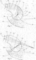
Fig. 7 ein weiteres Beispiel einer Beleuchtungsvorrichtung mit einem Freiformreflektor, wobei das Sekundäroptik als Kegel ausgebildet ist und das Primäroptikelement einen parabolisch geformten Bereich aufweist, -
Fig. 8 eine weitere beispielhafte Beleuchtungsvorrichtung mit einem Freiformreflektor, wobei das Sekundäroptikelement als Kegel ausgebildet ist und das Primäroptikelement einen hyperbolisch geformten Bereich aufweist, -
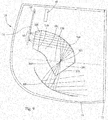
Fig. 9 zeigt schematisch einen Kraftfahrzeugscheinwerfer mit einer Beleuchtungsvorrichtung und einem zweiten Leuchtmittel, -
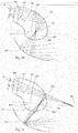
Fig. 10 ein weiteres Beispiel einer Beleuchtungsvorrichtung mit einem Freiformreflektor, wobei das Sekundäroptik als Teil eines Ellipsoiden ausgebildet ist und das Primäroptikelement einen parabolisch geformten Bereich aufweist, und -
Fig. 11 ein weiteres Beispiel einer Beleuchtungsvorrichtung mit einem Freiformreflektor, wobei das Sekundäroptik als Teil eines Ellipsoiden ausgebildet ist und das Primäroptikelement einen hyperbolisch geformten Bereich aufweist. - In
Fig. 1 ist ein in Hauptabstrahlrichtung eines ersten Leuchtmittels 50 angeordnetes, lichtleitendes Primäroptikelement 100 dargestellt, das auf einer dem ersten Leuchtmittel 50 zugewandten Seite eine Lichteinkoppelfläche 110 zur Einkopplung von Licht in das Primäroptikelement 100, auf eine dem ersten Leuchtmittel 50 abgewandten Seite eine Lichtauskoppelfläche 120 sowie eine sich zwischen der Lichteinkoppelfläche 110 und der Lichtauskoppelfläche 120 erstreckende Mantelfläche aufweist, an der das eingekoppelte Licht durch Totalreflexion in Richtung der Lichtauskoppelfläche 120 des Primäroptikelements weiterleitbar ist. - Unter "Hauptabstrahlrichtung" ist die Richtung zu verstehen, in der das erste Leuchtmittel infolge ihrer Richtwirkung am stärksten bzw. am meisten Licht abstrahlt.
- Die reflektierende Mantelfläche des Primäroptikelements 100 weist hierbei einen parabolisch geformten Bereich 150 mit einem Brennpunkt 151 auf, wobei der parabolisch geformte Bereich 150 ein Umlenken der durch die Lichteinkoppelfläche 110 des Primäroptikelements 100 eintretenden Lichtstrahlen in Richtung der Lichtauskoppelfläche 120 des Primäroptikelements 100 ermöglicht.
- In Hauptabstrahlrichtung des ersten Leuchtmittels 50, welche in
Fig. 1 zwei Lichtquellen in Form von LEDs umfasst, ist vor der Lichteinkoppelfläche 110 des Primäroptikelements 100 eine Vorsatzoptik 300 angeordnet, die eingerichtet ist, die von dem ersten Leuchtmittel 50 emittierten Lichtstrahlen zu parallelisieren oder zu fokussieren. - In dem Beispiel aus
Fig. 1 werden die Lichtstrahlen des ersten Leuchtmittels 50 von der Vorsatzoptik 300 parallelisiert bzw. kollimiert und so auf den parabolisch geformten Bereich 150 des Primäroptikelements 100 gelenkt, dass die Lichtstrahlen nach der Reflexion an dem parabolisch geformten Bereich 150 in dem Brennpunkt 151 des parabolisch geformten Bereichs 150 gebündelt werden bzw. diesen schneiden. - Ferner ist ein Sekundäroptikelement 200 in Lichtabstrahlrichtung nach der Lichtauskoppelfläche des Primäroptikelements 100 angeordnet, wobei das Sekundäroptikelement 200 auf einer der Lichtauskoppelfläche 120 des Primäroptikelements 100 zugewandten Seite eine Lichteinkoppelfläche 210 und auf einer dem Primäroptikelement 100 abgewandten Seite eine Lichtauskoppelfläche 220 aufweist.
- Das Sekundäroptikelement ist in
Fig. 1 als Teil einer Kugel mit einem Kugelmittelpunkt 201 ausgebildet, wobei der Brennpunkt 151 des parabolisch geformten Bereichs 150 des Primäroptikelements 100 und der Kugelmittelpunkt 201 in einem Punkt liegen. - Sowohl das Primäroptikelement 100 als auch das Sekundäroptikelement 200 sind in den gezeigten Beispielen aus einem Material gefertigt, wobei das Material eine höhere Brechzahl aufweist als das umgebende Medium des Primäroptikelements 100 bzw. des Sekundäroptikelements 200, beispielsweise Luft.
- Überdies ist das Primäroptikelement 100 und das Sekundäroptikelement 200 stoffschlüssig verbunden, wobei das Primäroptikelement 100 und das Sekundäroptikelement 200 vorzugsweise einstückig ausgebildet sind, also aus einem Stück gefertigt sind, und aus demselben Material bestehen, vorzugsweise Tarflon, d.h. dass die Lichtauskoppelfläche 120 des Primäroptikelements 100 und die Lichteinkoppelfläche 210 des Sekundäroptikelements 200 in einer gedachten Ebene liegen.
- Ferner kann, wie in den Figuren gezeigten Beispielen gezeigt ist, vorgesehen sein, dass die Vorsatzoptik 300 mit dem Primäroptikelement 100 stoffschlüssig verbunden ist, wobei vorzugsweise die Vorsatzoptik 300 einstückig mit dem Primäroptikelement 100 ausgebildet ist.
- Weiters ist in Lichtabstrahlrichtung nach der Lichtauskoppelfläche 220 des Sekundäroptikelements 200 ein parabolisch geformter Reflektor 400 mit einem Brennpunkt 401 angeordnet, wobei der Brennpunkt 401 des Reflektors 400 und der Kugelmittelpunkt 201 in einem Punkt liegen, d.h. dass der Kugelmittelpunkt 201, der Brennpunkt 151 des parabolisch geformten Bereichs 150 des Primäroptikelements 100 und der Brennpunkt 401 des parabolischen Reflektors 400 in einem Punkt liegen bzw. zusammenfallen.
- Der Reflektor erzeugt hierbei eine Lichtverteilung oder eine Teil-Lichtverteilung einer Lichtfunktion, beispielsweise eine Abblendlichtfunktion bzw. Abblendlichtverteilung oder eine Fernlichtfunktion bzw. eine Fernlichtverteilung. Vorzugsweise ist die Beleuchtungsvorrichtung in einem Kraftfahrzeugscheinwerfer bzw. als Kraftfahrzeugscheinwerfer in einem Kraftfahrzeug eingebaut, wobei die Beleuchtungsvorrichtung die oben genannten Lichtfunktionen bzw. Lichtverteilungen vor dem Kraftfahrzeug, insbesondere in Fahrtrichtung des Kraftfahrzeugs, erzeugt bzw. abbildet.
- Dies gilt allgemein für die gegenständliche Beleuchtungsvorrichtung sowie die nachfolgenden Ausführungsbeispiele in der Beschreibung.
- Der Begriff "Fahrtrichtung" bezeichnet in diesem Kontext die Richtung, in der sich ein angetriebenes Kraftfahrzeug wie konstruktiv vorgesehen bewegt. Ein technisch mögliches Rückwärtsfahren wird in diesem Zusammenhang nicht als Fahrtrichtung definiert.
- Die oben genannten, aufgezählten Lichtfunktionen bzw. Lichtverteilungen sind nicht abschließend, wobei die Beleuchtungsvorrichtung auch Kombinationen dieser Lichtfunktionen bzw. Lichtverteilungen erzeugen kann und/oder nur eine Teillichtverteilung erzeugt, beispielweise nur einen Teil einer Fern- oder Abblendlichtfunktion bzw. Verteilung.
- Es sei angemerkt, dass zur Erzeugung solcher Lichtfunktionen bzw. Lichtverteilungen die Beleuchtungsvorrichtung keine optischen Linsen umfasst.
- In
Fig. 1 sind weiters beispielhafte Strahlengänge zu sehen, die keine Umlenkungen durch das teilweise kugelförmige Sekundäroptikelement 200 erfahren, da die gezeigten Strahlengänge durch den Brennpunkt 151 des parabolisch geformten Bereichs 150 und somit auch dem Kugelmittelpunkt 201 verlaufen. - In
Fig. 2 ist eine weitere beispielhafte Ausführungsform zu sehen, wobei im Gegensatz zu dem Beispiel ausFig. 1 die reflektierende Mantelfläche des Primäroptikelements 100 einen hyperbolisch geformten Bereich 160 mit einem Brennpunkt 161 und einem virtuellen Brennpunkt 162 aufweist. Der hyperbolisch geformte Bereich 160 ermöglicht ein Umlenken der durch die Lichteinkoppelfläche 110 des Primäroptikelements 100 eintretenden Lichtstrahlen in Richtung der Lichtauskoppelfläche 120 des Primäroptikelements 100. - Ähnlich wie in
Fig. 1 liegen der Brennpunkt 161 des hyperbolisch geformten Bereichs 160 des Primäroptikelements 100 und der Kugelmittelpunkt 201 des Sekundäroptikelements 200 in einem Punkt. Ferner liegt auch der Brennpunkt 401 des parabolischen Reflektors 400 inFig. 2 und der Kugelmittelpunkt 201 in einem Punkt. - Die in
Fig. 2 gezeigte Vorsatzoptik 300 ist im Unterschied zu dem Beispiel ausFig. 1 dazu eingerichtet, die Lichtstrahlen des ersten Leuchtmittels 50 in dem virtuellen Brennpunkt 162 des hyperbolisch geformten Bereichs 160 des Primäroptikelements 100 zu fokussieren bzw. zu bündeln, wobei die Lichtstrahlen nach der Reflexion an dem hyperbolisch geformten Bereich 160 in dem Brennpunkt 161 des hyperbolisch geformten Bereichs 160 gebündelt werden bzw. diesen schneiden. -
Fig. 3 zeigt das Beispiel ausFig. 1 , wobei statt dem parabolischen Reflektor 400 ein hyperbolischer Reflektor 410 mit einem Brennpunkt 411 angeordnet ist. -
Fig. 4 zeigt das Beispiel ausFig. 2 , wobei statt dem parabolischen Reflektor 400 ein hyperbolischer Reflektor 410 mit einem Brennpunkt 411 angeordnet ist. - In
Fig. 5 ist ein Primäroptikelement 100 mit einer Lichteinkoppelfläche 110 und einer planaren Lichtauskoppelfläche 120 sowie ein in Lichtabstrahlrichtung nach der Lichtauskoppelfläche 120 des Primäroptikelements 100 angeordneter Reflektor dargestellt. Im Gegensatz zu den beispielhaften Ausführungsformen ausFig. 1, 2 ,3 und 4 , fehlt inFig. 5 ein Sekundäroptikelement 200. Weiters ist inFig. 5 ein möglicher Strahlengang eingezeichnet, wobei damit gezeigt werden soll, dass Lichtstrahlen beim Übergang von dem Primäroptikelement 100 in das umliegende Medium mit geringerer Brechzahl gemäß dem Brechungsgesetz derart an der planaren Lichtauskoppelfläche 120 des Primäroptikelements 100 gebrochen werden, dass diese vom Lot, welches ebenfalls in derFig. 5 dargestellt ist, weggebrochen werden und dadurch weniger Lichtstrahlen auf eine vom jeweilig verwendeten Reflektor abhängige, effektive Nutzfläche des entsprechenden Reflektors einfallen können. -
Fig. 6 zeigt im Wesentlichen die beispielhaften Ausführungen aus den vorhergehenden Figuren, wobei mit dem inFig. 6 eingezeichneten beispielhaften Strahlengang verdeutlicht werden soll, wie Lichtstrahlen beim Übergang von dem Sekundärelement 200 in das umliegende Medium mit geringerer Brechzahl an der Lichtauskoppelfläche 220 des Sekundäroptikelements 200 gebrochen werden im Gegensatz zu dem Strahlengang aus der vorherigenFig. 5 . Hierbei ist es unerheblich, ob der reflektierende Bereich der Mantelfläche des Primäroptikelements 100 einen parabolisch oder hyperbolisch geformten Bereich aufweist. - Im Gegensatz zu den dargestellten Beispielen aus
Fig. 1, 2 ,3 und 4 , ist ein beispielhafter Strahlengang gezeigt, der nach der Reflexion an der Mantelfläche des Primäroptikelements nicht durch den entsprechenden Brennpunkt 151, 161 bzw. den Kugelmittelpunkt 201 verläuft, wobei der jeweilige Brennpunkt abhängig davon ist, ob das Primäroptikelement einen parabolisch oder einen hyperbolisch geformten Bereich 150,160 aufweist. - Durch die als Teil einer Kugelfläche ausgebildete Lichtauskoppelfläche 220 des Sekundäroptikelements 200 wird der gleiche beispielhafte Lichtstrahl aus
Fig. 5 auf die effektive Nutzfläche eines in Lichtaustrittsrichtung nachgeschalteten Reflektors gebrochen. - Es sei darauf hingewiesen, dass die in
Fig. 5 gezeigte Beleuchtungsvorrichtung kein erfindungsgemäßes Beispiel darstellt. - In
Fig. 7 ist eine weitere beispielhafte Ausführungsform zu sehen, wobei im Gegensatz zu dem Beispiel aus den vorherigen Figuren das Sekundärelement 250 als Kegel mit einer Kegelgrundfläche und der Reflektor als Freiformreflektor 420 ausgebildet ist. Der Mittelpunkt der Kegelgrundfläche, welche gleichzeitig die Lichteinkoppelfläche 260 des als Kegel ausgebildeten Sekundäroptikelements darstellt, kann vorteilhafterweise so angeordnet sein, dass er mit dem Brennpunkt 151 des parabolisch geformten Bereichs 150 zusammenfällt. Die Mantelfläche des Kegels 250 stellt die Lichtauskoppelfläche 270 des Sekundäroptikelements 250 dar. - Ein Freiformreflektor ist ein Reflektor, dessen besondere Eigenschaft es ist, dass die Reflektorform keiner mathematischen Regelfläche entspricht.
- Das Primäroptikelement 100 weist in dem in
Fig. 7 gezeigt Beispiel einen parabolisch geformten Bereich 150 mit einem Brennpunkt 151 auf, wobei die Vorsatzoptik 300 die Lichtstrahlen des ersten Leuchtmittels 50 parallelisiert bzw. kollimiert und so auf den parabolisch geformten Bereich 150 des Primäroptikelements 100 lenkt, dass die Lichtstrahlen nach der Reflexion an dem parabolisch geformten Bereich 150 in dem Brennpunkt 151 des parabolisch geformten Bereichs 150 gebündelt werden bzw. diesen schneiden. -
Fig. 8 zeigt eine weitere beispielhafte Ausführungsform, wobei im Gegensatz zu dem vorherigen Beispiel ausFig. 7 die reflektierende Mantelfläche des Primäroptikelements 100 einen hyperbolisch geformten Bereich 160 mit einem reellen Brennpunkt 161 und einem virtuellen Brennpunkt 162 aufweist und die gezeigte Vorsatzoptik 300 dazu eingerichtet ist, die Lichtstrahlen des ersten Leuchtmittels 50 in dem virtuellen Brennpunkt 162 des hyperbolisch geformten Bereichs 160 des Primäroptikelements 100 zu fokussieren bzw. zu bündeln, wobei die Lichtstrahlen nach der Reflexion an dem hyperbolisch geformten Bereich 160 in dem Brennpunkt 161 des hyperbolisch geformten Bereichs 160 gebündelt werden bzw. diesen schneiden. Der Mittelpunkt der Kegelgrundfläche fällt in diesem Ausführungsbeispiel nicht mit dem Brennpunkt 161 des hyperbolisch geformten Bereichs 160 zusammen, wobei auch hier vorgesehen sein kann, dass der Mittelpunkt der Kegelgrundfläche mit dem Brennpunkt 161 des hyperbolisch geformten Bereichs zusammenfällt. - Die in
Fig. 7 und 8 dargestellten Lichtstrahlen bzw. Strahlengänge zeigen, dass die Lichtstrahlen - verglichen mit einer planaren Auskoppelfläche 120 - durch das als Kegel ausgebildete Sekundäroptikelement 250 gebündelter bzw. konzentrierter auf einen effektiven Nutzbereich des Freiformreflektors 420 einfallen. - In
Fig. 9 ist ein Kraftfahrzeugscheinwerfer 10 mit einem Gehäuse 11 und einer Abdeckscheibe 12, die nicht als optische Linse fungiert, wobei eine Beleuchtungsvorrichtung in dem Kraftfahrzeugscheinwerfer 10 angeordnet ist. - Hierbei umfasst die Beleuchtungsvorrichtung wie in den vorherigen Beispielen ein erstes Leuchtmittel 50, welches zur Erzeugung einer Lichtverteilung oder einer Teil-Lichtverteilung einer ersten Lichtfunktion, beispielsweise Abblendlicht oder Fernlicht, vorgesehen ist, wobei die von dem ersten Leuchtmittel 50 emittierten Lichtstrahlen durch einen Kollimator 300 parallel auf einen parabolisch geformten Mantelbereich 150 eines Primäroptikelements 100 mit einem Brennpunkt 151 treffen.
- Der parabolisch geformte Bereich 150 ermöglicht ein Umlenken der einfallenden Lichtstrahlen in Richtung einer Lichtauskoppelfläche 120 des Primäroptikelements 100. In Lichtabstrahlrichtung nach der Lichtauskoppelfläche 120 des Primäroptikelements 100 ist eine Lichteinkoppelfläche 260 eines Sekundäroptikelements 250 angeordnet, welches Sekundäroptikelement 250 in dem Beispiel aus
Fig. 9 als Kegel mit einer Kegelgrundfläche ausgebildet ist. Der Mittelpunkt der Kegelgrundfläche kann, wie in den vorherigen Ausführungsbeispielen erwähnt, mit dem Brennpunkt 151 des Primäroptikelements 100 zusammenfallen. - Eine Diskussion der Strahlenverläufe hinsichtlich des ersten Leuchtmittels 50 wurde bereits in den vorherigen Beispielen erläutert und ist diesen im Zusammenhang mit den Ausführungsbeispiel in
Fig. 9 zu entnehmen. - Der Kraftfahrzeugscheinwerfer 10 in
Fig. 9 umfasst ferner ein zweites Leuchtmittel 60, das inFig. 9 als LED ausgeführt ist und zur Erzeugung einer Lichtverteilung oder einer Teil-Lichtverteilung einer zweiten Lichtfunktion, beispielsweise Abblendlicht oder Fernlicht, vorgesehen ist, wobei das erste und das zweite Leuchtmittel 50, 60 auf einer gemeinsamen Leiterplatte 70 angeordnet sind. Hinsichtlich der Vollständigkeit ist eine in Hauptabstrahlrichtung des zweiten Leuchtmittels 60 nachgeschaltete, Licht formende Optik 65 angeordnet, welche beispielsweise als Linse oder als Reflektor ausgebildet sein kann. Aus Gründen der Übersichtlichkeit wurde auf mögliche Strahlengänge - ausgehend von dem zweiten Leuchtmittel 60 - verzichtet. - So ist es möglich, die Leuchtmittel 50, 60, welche jeweils zur Erzeugung von unterschiedlichen Lichtfunktionen vorgesehen sind, beispielsweise Abblendlicht und Fernlicht, auf einer gemeinsamen Leiterplatte 70 anzuordnen bzw. herzustellen.
- Diese Vorgehensweise wirkt sich in der Regel platzsparend in einem Kraftfahrzeugscheinwerfer aus, wobei nun dafür gesorgt werden muss, dass beide Lichtfunktionen separat und/oder gemeinsam ohne gegenseitige Beeinflussung vor dem Kraftfahrzeug erzeugt werden können, wobei das Primäroptikelement 100, das Sekundäroptikelement 200 und gegebenenfalls die Vorsatzoptik 300 gewissermaßen als Umlenkoptik dienen.
- Weiters können die Leuchtmittel 50, 60 unabhängig voneinander ansteuer- und dimmbar sein.
-
Fig. 10 und Fig. 11 zeigen jeweils weitere Beleuchtungsvorrichtungen, wobei der Aufbau der Beleuchtungsvorrichtungen inFig. 10 und Fig. 11 den Beispielen ausFig. 7 und Fig. 8 im Wesentlichen gleichen, wohingegen das Sekundärelement 500 inFig. 10 und 11 als Teil eines Ellipsoiden ausgebildet ist. - Die Ausführungsform in
Fig. 10 zeigt ferner ein erstes Leuchtmittel 50 sowie ein Primäroptikelement 100 mit einem parabolisch ausgeformten Bereich 150, wobei die Lichtstrahlen des ersten Leuchtmittels 50 auf den parabolisch geformten Bereich 150 einfallen und in einem Brennpunkt 151 des parabolisch geformten Bereichs 150 gebündelt umgelenkt werden bzw. diesen Brennpunkt 151 schneiden. Der Brennpunkt 151 liegt vorzugsweise in einer Lichteinkoppelfläche 510 des als Teil eines Ellipsoiden ausgebildeten Sekundäroptikelements 500, wobei die Lichtstrahlen über eine Lichtauskoppelfläche 520 des Sekundärelements 500 auf einen Freiformreflektor 420 fallen. - Die Ausführungsform in
Fig. 11 zeigt weiters ein erstes Leuchtmittel 50 sowie ein Primäroptikelement 100 mit einem hyperbolisch ausgeformten Bereich 160, wobei die Lichtstrahlen des ersten Leuchtmittels 50 auf den hyperbolisch geformten Bereich 160 einfallen und in einem reellen Brennpunkt 161 des parabolisch geformten Bereichs 160 gebündelt umgelenkt werden bzw. diesen reellen Brennpunkt 161 schneiden. Der Brennpunkt 161 liegt vorzugsweise in einer Lichteinkoppelfläche 510 des als Teil eines Ellipsoiden ausgebildeten Sekundäroptikelements 500, wobei die Lichtstrahlen über eine Lichtauskoppelfläche 520 des Sekundärelements 500 auf einen Freiformreflektor 420 fallen. - Für eine genauere Analyse der jeweiligen Strahlengänge sei auf die vorherigen Beispiele und dazu getätigten Ausführungen verwiesen.
- Es sei weiters darauf hingewiesen, dass die in den Figuren gezeigten Beispiele bzw. Ausführungsformen eine nicht abschließende Anzahl an Beispielen und deren Kombinationsmöglichkeiten offenbart, so kann auch vorgesehen sein, dass beispielsweise ein Freiformreflektor für die Beispiele in den
Fig. 1, 2 ,3, 4 ,5 und 6 angeordnet sein kann. - Ebenso können abseits des gezeigten Ausführungsbeispiels aus
Fig. 9 die anderen offenbarten Beispiele - und auch Kombinationen davon - in einem Kraftfahrzeugscheinwerfer angeordnet sein. -
- Kraftfahrzeugscheinwerfer
- 10
- Scheinwerfergehäuse
- 11
- Abdeckscheibe
- 12
- Erstes Leuchtmittel
- 50
- Zweites Leuchtmittel
- 60
- Licht formende Optik
- 65
- Leiterplatte
- 70
- Primäroptikelement
- 100
- Lichteinkoppelfläche (PO)
- 110
- Lichtauskoppelfläche (PO)
- 120
- Parallel geformter Bereich
- 150
- Brennpunkt par. geformter Bereich
- 151
- Hyperbolisch geformter Bereich
- 160
- Brennpunkt hyp. geformter Bereich
- 161
- Virtueller Brennpunkt hyp. gef. Bereich
- 162
- Sekundäroptikelement (Kugel)
- 200
- Kugelmittelpunkt
- 201
- Lichteinkoppelfläche (SO - Kugel)
- 210
- Lichtauskoppelfläche (SO - Kugel)
- 220
- Sekundäroptikelement (Kegel)
- 250
- Lichteinkoppelfläche (SO - Kegel)
- 260
- Lichtauskoppelfläche (SO - Kegel)
- 270
- Vorsatzoptik
- 300
- Hyperbolischer Reflektor
- 400
- Brennpunkt hyp. Reflektor
- 401
- Parabolischer Reflektor
- 410
- Brennpunkt par. Reflektor
- 411
- Freiformreflektor
- 420
- Sekundäroptikelement (Ellipsoid)
- 500
- Lichteinkoppelfläche (SO - Ellipsoid)
- 510
- Lichtauskoppelfläche (SO - Ellipsoid)
- 520
Claims (21)
- Beleuchtungsvorrichtung für einen Kraftfahrzeugscheinwerfer, umfassend- ein in Hauptabstrahlrichtung eines ersten Leuchtmittels (50) angeordnetes, lichtleitendes Primäroptikelement (100), das auf einer dem ersten Leuchtmittel (50) zugewandten Seite eine Lichteinkoppelfläche (110) zur Einkopplung von Lichtstrahlen in das Primäroptikelement (100), auf eine dem ersten Leuchtmittel (50) abgewandten Seite eine Lichtauskoppelfläche (120) sowie eine sich zwischen der Lichteinkoppelfläche (110) und der Lichtauskoppelfläche (120) erstreckende Mantelfläche aufweist, an der das eingekoppelte Licht durch Totalreflexion in Richtung der Lichtauskoppelfläche (120) des Primäroptikelements (100) weiterleitbar ist,- ein in Lichtabstrahlrichtung nach der Lichtauskoppelfläche (120) des Primäroptikelements (100) angeordnetes Sekundäroptikelement (200, 250, 500), das auf einer der Lichtauskoppelfläche (120) des Primäroptikelements (100) zugewandten Seite eine Lichteinkoppelfläche (210, 260, 510) und auf einer dem Primäroptikelement (100) abgewandten Seite eine Lichtauskoppelfläche (220, 270, 520) aufweist, und- einen in Lichtabstrahlrichtung nach der Lichtauskoppelfläche (220, 270, 520) des Sekundäroptikelements (200, 250, 500) angeordneten, zur Erzeugung einer Lichtverteilung oder einer Teil-Lichtverteilung einer Lichtfunktion vorgesehenen Reflektor (400, 410, 420),dadurch gekennzeichnet, dass
das Sekundäroptikelement (200, 250, 500) als Teil einer Quadrik ausgebildet ist, wobei das Sekundäroptikelement (200, 250, 500) eingerichtet ist, die von dem ersten Leuchtmittel (50) emittierten Lichtstrahlen, welche die Lichtauskoppelfläche (220, 270, 520) des Sekundäroptikelements (200, 250, 500) erreichen, beim Auskoppeln mittels Brechung auf den Reflektor (400, 410, 420) zu lenken oder ohne Richtungsänderung passieren zu lassen. - Beleuchtungsvorrichtung nach Anspruch 1, dadurch gekennzeichnet, dass das Sekundäroptikelement (200) als Teil einer Kugel mit einem Kugelmittelpunkt (201) oder als Kegel oder als Teil eines Ellipsoiden ausgebildet ist.
- Vorrichtung nach Anspruch 1 oder 2, dadurch gekennzeichnet, dass die reflektierende Mantelfläche des Primäroptikelements (100) einen parabolisch geformten Bereich (150) mit einem Brennpunkt (151) aufweist, wobei der parabolisch geformte Bereich (150) ein Umlenken der durch die Lichteinkoppelfläche (110) des Primäroptikelements (100) eintretenden Lichtstrahlen in Richtung der Lichtauskoppelfläche (120) des Primäroptikelements (100) ermöglicht.
- Vorrichtung nach Anspruch 3, dadurch gekennzeichnet, dass der Brennpunkt (151) des parabolisch geformten Bereichs (150) des Primäroptikelements (100) und der Kugelmittelpunkt (201) in einem Punkt liegen.
- Vorrichtung nach Anspruch 1 oder 2, dadurch gekennzeichnet, dass die reflektierende Mantelfläche des Primäroptikelements (100) einen hyperbolisch geformten Bereich (160) mit einem Brennpunkt (161) und einem virtuellen Brennpunkt (162) aufweist, wobei der hyperbolisch geformte Bereich (160) ein Umlenken der durch die Lichteinkoppelfläche (110) des Primäroptikelements (100) eintretenden Lichtstrahlen in Richtung der Lichtauskoppelfläche (120) des Primäroptikelements (100) ermöglicht.
- Vorrichtung nach Anspruch 5, dadurch gekennzeichnet, dass der Brennpunkt (161) des hyperbolisch geformten Bereichs (160) des Primäroptikelements (100) und der Kugelmittelpunkt (201) in einem Punkt liegen.
- Vorrichtung nach einem der Ansprüche 1 bis 6, dadurch gekennzeichnet, dass in Hauptabstrahlrichtung des ersten Leuchtmittels (50) vor der Lichteinkoppelfläche (110) des Primäroptikelements (100) eine Vorsatzoptik (300) angeordnet ist, die eingerichtet ist, die von dem ersten Leuchtmittel (50) emittierten Lichtstrahlen zu parallelisieren oder auf einen Punkt zu fokussieren.
- Vorrichtung nach Anspruch 7, dadurch gekennzeichnet, dass die Vorsatzoptik (300) dazu eingerichtet ist, die Lichtstrahlen des ersten Leuchtmittels (50) auf den virtuellen Brennpunkt (162) des hyperbolisch geformten Bereichs (160) des Primäroptikelements (100) zu fokussieren.
- Vorrichtung nach einem der Ansprüche 1 bis 8, dadurch gekennzeichnet, dass das Primäroptikelement (100) und das Sekundäroptikelement (200, 250, 500) stoffschlüssig miteinander verbunden sind, wobei vorzugsweise das Primäroptikelement (100) und das Sekundäroptikelement (200, 250, 500) einstückig ausgebildet sind und aus demselben Material bestehen.
- Vorrichtung nach Anspruch 9, dadurch gekennzeichnet, dass die Vorsatzoptik (300) mit dem Primäroptikelement (100) stoffschlüssig verbunden ist, wobei vorzugsweise die Vorsatzoptik (300) einstückig mit dem Primäroptikelement (100) ausgebildet ist.
- Vorrichtung nach einem der Ansprüche 1 bis 10, dadurch gekennzeichnet, dass das Primäroptikelement (100) und das Sekundäroptikelement (200, 250, 500) aus Tarflon gebildet sind.
- Vorrichtung nach einem der Ansprüche 1 bis 11, dadurch gekennzeichnet, dass das erste Leuchtmittel (50) zumindest eine Lichtquelle aufweist, wobei vorzugsweise die zumindest eine Lichtquelle als LED oder als Laserlichtquelle mit einem Lichtkonversionselement ausgebildet ist.
- Vorrichtung nach einem der Ansprüche 1 bis 12, dadurch gekennzeichnet, dass das erste Leuchtmittel (50) zur Erzeugung einer Lichtverteilung oder einer Teil-Lichtverteilung einer ersten Lichtfunktion, beispielsweise Abblendlicht oder Fernlicht, vorgesehen ist.
- Vorrichtung nach einem der Ansprüche 1 bis 13, dadurch gekennzeichnet, dass der Reflektor als Freiformreflektor (420) ausgebildet ist.
- Vorrichtung nach einem der Ansprüche 1 bis 14, dadurch gekennzeichnet, dass der Reflektor als parabolischer Reflektor (400) mit einem Brennpunkt (401) ausgebildet ist.
- Vorrichtung nach Anspruch 1, dadurch gekennzeichnet, dass der Brennpunkt (401) des parabolischen Reflektors (400) und der Kugelmittelpunkt in einem Punkt liegen.
- Vorrichtung nach einem der Ansprüche 1 bis 16, dadurch gekennzeichnet, dass der Reflektor als hyperbolischer Reflektor (410) mit einem Brennpunkt (411) ausgebildet ist.
- Vorrichtung nach Anspruch 17, dadurch gekennzeichnet, dass der Brennpunkt (411) des hyperbolischen Reflektors (410) und der Kugelmittelpunkt (201) in einem Punkt liegen.
- Kraftfahrzeugscheinwerfer (10) mit zumindest einer Beleuchtungsvorrichtung nach einem der Ansprüche 1 bis 18.
- Kraftfahrzeugscheinwerfer nach Anspruch 19, dadurch gekennzeichnet, dass der Kraftfahrzeugscheinwerfer (10) ferner ein zweites Leuchtmittel (60) zur Erzeugung einer Lichtverteilung oder einer Teil-Lichtverteilung einer zweiten Lichtfunktion, beispielsweise Abblendlicht oder Fernlicht, vorgesehen ist, wobei vorzugsweise das zweite Leuchtmittel (60) zumindest eine Lichtquelle aufweist, wobei insbesondere die zumindest eine Lichtquelle als LED oder als Laserlichtquelle mit einem Lichtkonversionselement ausgebildet ist.
- Kraftfahrzeugscheinwerfer nach Anspruch 20, dadurch gekennzeichnet, dass das erste und das zweite Leuchtmittel (50, 60) auf einer gemeinsamen Leiterplatte (70) angeordnet sind.
Priority Applications (6)
| Application Number | Priority Date | Filing Date | Title |
|---|---|---|---|
| EP17197220.1A EP3473918B1 (de) | 2017-10-19 | 2017-10-19 | Beleuchtungsvorrichtung für einen kraftfahrzeugscheinwerfer |
| KR1020207013113A KR102378717B1 (ko) | 2017-10-19 | 2018-09-13 | 자동차 헤드램프용 조명 장치 |
| JP2020522041A JP6931423B2 (ja) | 2017-10-19 | 2018-09-13 | 自動車投光器用の照明装置 |
| CN201880068053.3A CN111201399B (zh) | 2017-10-19 | 2018-09-13 | 用于机动车大灯的照明装置 |
| PCT/EP2018/074782 WO2019076550A1 (de) | 2017-10-19 | 2018-09-13 | Beleuchtungsvorrichtung für einen kraftfahrzeugscheinwerfer |
| US16/755,798 US11104265B2 (en) | 2017-10-19 | 2018-09-13 | Lighting device for a motor vehicle headlight |
Applications Claiming Priority (1)
| Application Number | Priority Date | Filing Date | Title |
|---|---|---|---|
| EP17197220.1A EP3473918B1 (de) | 2017-10-19 | 2017-10-19 | Beleuchtungsvorrichtung für einen kraftfahrzeugscheinwerfer |
Publications (2)
| Publication Number | Publication Date |
|---|---|
| EP3473918A1 true EP3473918A1 (de) | 2019-04-24 |
| EP3473918B1 EP3473918B1 (de) | 2021-12-01 |
Family
ID=60143589
Family Applications (1)
| Application Number | Title | Priority Date | Filing Date |
|---|---|---|---|
| EP17197220.1A Active EP3473918B1 (de) | 2017-10-19 | 2017-10-19 | Beleuchtungsvorrichtung für einen kraftfahrzeugscheinwerfer |
Country Status (6)
| Country | Link |
|---|---|
| US (1) | US11104265B2 (de) |
| EP (1) | EP3473918B1 (de) |
| JP (1) | JP6931423B2 (de) |
| KR (1) | KR102378717B1 (de) |
| CN (1) | CN111201399B (de) |
| WO (1) | WO2019076550A1 (de) |
Cited By (1)
| Publication number | Priority date | Publication date | Assignee | Title |
|---|---|---|---|---|
| FR3161016A1 (fr) * | 2024-04-03 | 2025-10-10 | Stellantis Auto Sas | Bloc optique à réflecteur(s) alimenté(s) en photons par le bas |
Families Citing this family (7)
| Publication number | Priority date | Publication date | Assignee | Title |
|---|---|---|---|---|
| KR102949241B1 (ko) * | 2021-03-29 | 2026-04-07 | 에스엘 주식회사 | 차량용 램프 |
| KR102838234B1 (ko) * | 2021-03-29 | 2025-07-24 | 에스엘 주식회사 | 차량용 램프 |
| CN113091014B (zh) * | 2021-04-06 | 2022-02-22 | 华域视觉科技(上海)有限公司 | 车灯光学元件、车灯模组和车辆 |
| EP4194896B1 (de) * | 2021-12-07 | 2025-11-19 | ZKW Group GmbH | Radarmodul für eine kraftfahrzeugleuchte |
| EP4357667A1 (de) * | 2022-10-21 | 2024-04-24 | ZKW Group GmbH | Beleuchtungseinrichtung für einen kraftfahrzeugscheinwerfer zur erzeugung einer lichtverteilung |
| EP4428434A1 (de) * | 2023-03-08 | 2024-09-11 | ZKW Group GmbH | Signalvorrichtung für ein fahrzeug |
| EP4621285A1 (de) * | 2024-03-21 | 2025-09-24 | ZKW Group GmbH | Beleuchtungsvorrichtung für ein kraftfahrzeug |
Citations (8)
| Publication number | Priority date | Publication date | Assignee | Title |
|---|---|---|---|---|
| US20050201114A1 (en) * | 2004-03-11 | 2005-09-15 | Koito Manufacturing Co., Ltd. | Vehicle lamp unit |
| WO2006060392A2 (en) * | 2004-11-30 | 2006-06-08 | Magna International Inc. | Hybrid optics for l.e.d. lamp |
| US20070037906A1 (en) * | 2003-10-07 | 2007-02-15 | Idemitsu Kosan Co., Ltd. | Polycarbonate resin composition and optical part |
| DE102011009100A1 (de) * | 2011-01-21 | 2012-03-15 | Audi Ag | Kraftfahrzeugbeleuchtungseinrichtung zur Innenraumbeleuchtung oder zur Außenbeleuchtung |
| WO2012040280A2 (en) * | 2010-09-21 | 2012-03-29 | Federal-Mogul Ignition Company | Led light module |
| WO2013134805A1 (de) * | 2012-03-12 | 2013-09-19 | Zizala Lichtsysteme Gmbh | Lichtleitelement für einen laser-fahrzeugscheinwerfer |
| WO2016005409A1 (fr) * | 2014-07-11 | 2016-01-14 | Valeo Vision | Module lumineux d'un véhicule automobile |
| CN105716023A (zh) * | 2016-04-26 | 2016-06-29 | 曹红曲 | 一种汽车前照灯组件及汽车前照灯 |
Family Cites Families (23)
| Publication number | Priority date | Publication date | Assignee | Title |
|---|---|---|---|---|
| CH304170A (de) * | 1952-03-13 | 1954-12-31 | Inventor Credit Anstalt | Reflexionsanlage. |
| DE4301291C2 (de) * | 1993-01-15 | 1999-08-19 | Gallert | Universeller Zweispiegelkorrektor für Cassegrain- und Ritchey- Chretien -Spiegelsysteme |
| DE19738706A1 (de) * | 1997-08-29 | 1999-03-04 | Frank Gallert | Dreispiegelsystem mit vier Reflexionen |
| JP4339143B2 (ja) * | 2004-02-10 | 2009-10-07 | 株式会社小糸製作所 | 車両用灯具ユニット |
| JP2006127856A (ja) * | 2004-10-27 | 2006-05-18 | Koito Mfg Co Ltd | 車両用照明灯具 |
| EP1815287A1 (de) * | 2004-11-18 | 2007-08-08 | Koninklijke Philips Electronics N.V. | Beleuchtungssystem und fahrzeug-scheinwerfer |
| FR2884899B1 (fr) * | 2005-04-21 | 2007-06-15 | Valeo Vision Sa | Module d'eclairage donnant un faisceau lumineux avec coupure pour projecteur de vehicule automobile, et projecteur comprenant un tel module |
| JP4468857B2 (ja) * | 2005-05-17 | 2010-05-26 | 株式会社小糸製作所 | 車両用照明灯具 |
| ATE553155T1 (de) * | 2006-12-25 | 2012-04-15 | Mitsubishi Rayon Co | Fliessfähigkeitsverbesserer, aromatisches polycarbonatharz enthaltende zusammensetzung und formkörper daraus |
| JP5677122B2 (ja) * | 2011-02-15 | 2015-02-25 | スタンレー電気株式会社 | 車両用灯具 |
| JP5707661B2 (ja) * | 2011-03-25 | 2015-04-30 | スタンレー電気株式会社 | 車両用灯具ユニット及び車両用灯具に用いられる導光体 |
| JP5686039B2 (ja) | 2011-05-24 | 2015-03-18 | 市光工業株式会社 | 車両用灯具 |
| JP5945857B2 (ja) * | 2012-01-24 | 2016-07-05 | スタンレー電気株式会社 | 車両用前照灯及び導光レンズ |
| AT512591B1 (de) * | 2012-03-12 | 2014-06-15 | Zizala Lichtsysteme Gmbh | Fahrzeugscheinwerfer mit Laserlichtquelle |
| FR2992711B1 (fr) * | 2012-06-28 | 2018-08-10 | Valeo Vision | Dispositif optique de vehicule automobile a elements dioptriques integres au conduit de lumiere |
| JP5941383B2 (ja) | 2012-09-19 | 2016-06-29 | 株式会社小糸製作所 | 車両用灯具 |
| DE102013215374A1 (de) * | 2013-08-05 | 2015-02-05 | Osram Opto Semiconductors Gmbh | Beleuchtungsanordnung |
| FR3012867A1 (fr) * | 2013-11-07 | 2015-05-08 | Valeo Vision | Element optique primaire, module lumineux et projecteur pour vehicule automobile |
| SG11201609505XA (en) * | 2014-06-13 | 2016-12-29 | Umg Abs Ltd | Thermoplastic resin composition and molded product thereof |
| AT516422B1 (de) * | 2014-10-21 | 2016-07-15 | Zizala Lichtsysteme Gmbh | Verfahren und Scheinwerfer zum Erzeugen einer Lichtverteilung auf einer Fahrbahn |
| AT517105B1 (de) * | 2015-06-29 | 2016-11-15 | Zkw Group Gmbh | Lichtleiteranordnung zur Erzeugung von zumindest einer Beleuchtungsfunktion und/oder Signalisierungsfunktion eines Kraftfahrzeugscheinwerfers |
| FR3039883B1 (fr) * | 2015-08-06 | 2020-10-02 | Valeo Vision | Module lumineux en materiau transparent avec deux faces de reflexion |
| CN108139056B (zh) * | 2015-10-13 | 2020-07-07 | 三菱电机株式会社 | 前照灯用光源及移动体用前照灯 |
-
2017
- 2017-10-19 EP EP17197220.1A patent/EP3473918B1/de active Active
-
2018
- 2018-09-13 KR KR1020207013113A patent/KR102378717B1/ko not_active Expired - Fee Related
- 2018-09-13 CN CN201880068053.3A patent/CN111201399B/zh active Active
- 2018-09-13 WO PCT/EP2018/074782 patent/WO2019076550A1/de not_active Ceased
- 2018-09-13 JP JP2020522041A patent/JP6931423B2/ja active Active
- 2018-09-13 US US16/755,798 patent/US11104265B2/en active Active
Patent Citations (8)
| Publication number | Priority date | Publication date | Assignee | Title |
|---|---|---|---|---|
| US20070037906A1 (en) * | 2003-10-07 | 2007-02-15 | Idemitsu Kosan Co., Ltd. | Polycarbonate resin composition and optical part |
| US20050201114A1 (en) * | 2004-03-11 | 2005-09-15 | Koito Manufacturing Co., Ltd. | Vehicle lamp unit |
| WO2006060392A2 (en) * | 2004-11-30 | 2006-06-08 | Magna International Inc. | Hybrid optics for l.e.d. lamp |
| WO2012040280A2 (en) * | 2010-09-21 | 2012-03-29 | Federal-Mogul Ignition Company | Led light module |
| DE102011009100A1 (de) * | 2011-01-21 | 2012-03-15 | Audi Ag | Kraftfahrzeugbeleuchtungseinrichtung zur Innenraumbeleuchtung oder zur Außenbeleuchtung |
| WO2013134805A1 (de) * | 2012-03-12 | 2013-09-19 | Zizala Lichtsysteme Gmbh | Lichtleitelement für einen laser-fahrzeugscheinwerfer |
| WO2016005409A1 (fr) * | 2014-07-11 | 2016-01-14 | Valeo Vision | Module lumineux d'un véhicule automobile |
| CN105716023A (zh) * | 2016-04-26 | 2016-06-29 | 曹红曲 | 一种汽车前照灯组件及汽车前照灯 |
Cited By (1)
| Publication number | Priority date | Publication date | Assignee | Title |
|---|---|---|---|---|
| FR3161016A1 (fr) * | 2024-04-03 | 2025-10-10 | Stellantis Auto Sas | Bloc optique à réflecteur(s) alimenté(s) en photons par le bas |
Also Published As
| Publication number | Publication date |
|---|---|
| US20210162910A1 (en) | 2021-06-03 |
| JP2020537813A (ja) | 2020-12-24 |
| WO2019076550A1 (de) | 2019-04-25 |
| KR20200067177A (ko) | 2020-06-11 |
| JP6931423B2 (ja) | 2021-09-01 |
| KR102378717B1 (ko) | 2022-03-25 |
| CN111201399B (zh) | 2022-06-03 |
| CN111201399A (zh) | 2020-05-26 |
| EP3473918B1 (de) | 2021-12-01 |
| US11104265B2 (en) | 2021-08-31 |
Similar Documents
| Publication | Publication Date | Title |
|---|---|---|
| EP3545229B1 (de) | Beleuchtungseinrichtung eines kraftfahrzeugscheinwerfers | |
| EP3473918B1 (de) | Beleuchtungsvorrichtung für einen kraftfahrzeugscheinwerfer | |
| EP2917635B1 (de) | Kfz.-beleuchtungsvorrichtung | |
| EP2799761B1 (de) | Lichtmodul für einen kraftfahrzeugscheinwerfer | |
| EP1630576B1 (de) | Leuchtmittel mit vorgegebener Abstrahlcharakteristik und Primäroptikelement für ein Leuchtmittel | |
| EP1818599B1 (de) | Abblendlichtscheinwerfer, der einen kontraststark ausgebildeten Cut-off erzeugt | |
| DE102010056313C5 (de) | Beleuchtungseinrichtung eines Kraftfahrzeugs | |
| DE602004002043T2 (de) | Elliptische Beleuchtungseinheit ohne Lichtblende zur Erzeugung eines Abblendlichtbündels und Scheinwerfer mit einer derartigen Belleuchtungseinheit | |
| DE102010041096A1 (de) | Leuchtvorrichtung | |
| EP1818600B1 (de) | Abblendlichtscheinwerfer mit Hot-Spot-Erzeugung | |
| DE102011085314B3 (de) | Lichtmodul einer Beleuchtungseinrichtung eines Kraftfahrzeugs | |
| WO2011154470A1 (de) | Vorsatzoptik aus transparentem material zum bündeln von licht, linsenarray mit mindestens einer solchen vorsatzoptik und lichtmodul mit einem solchen linsenarray | |
| DE102013200521B4 (de) | Primäroptikeinrichtung für KFZ-Schweinwerfer mit Laserlichtquelle, schichtartigem Photolumineszenzelement, Lichtleitelement und Reflexionsflächen für Licht des Photolumineszenzelements und entsprechender KFZ-Scheinwerfer | |
| DE102014221389A1 (de) | Lichtmodul einer Beleuchtungseinrichtung und Beleuchtungseinrichtung mit einem solchen Lichtmodul | |
| DE102014116983B4 (de) | Laseroptisches system für einen fahrzeug-frontscheinwerfer, bei dem eine einen laserstrahl fokussierende strahllinse in unmittelbarem kontakt mit einem vom laserstrahl angeregten leuchtkörper ist | |
| DE102005043992B4 (de) | Signalleuchte eines Fahrzeugs | |
| EP3604903A1 (de) | Kraftfahrzeugscheinwerfer mit einem ellipsoid-reflektor und kollimator | |
| DE102017213103A1 (de) | Beleuchtungssystem und scheinwerfer | |
| WO2021004805A1 (de) | Beleuchtungsvorrichtung für ein kraftfahrzeug | |
| WO2012150121A1 (de) | Strahlungsemittierende vorrichtung und verwendung einer derartigen vorrichtung | |
| DE102015106022A1 (de) | Abstrahleinheit für eine Operationsleuchte | |
| DE102012215124A1 (de) | Beleuchtungseinrichtung mit Lichtquelle, Lichtleitkörper und Reflektor | |
| DE102011087309A1 (de) | Leuchtvorrichtung | |
| DE102014208504A1 (de) | Beleuchtungseinrichtung | |
| DE102017117560A1 (de) | Lichtmodul und Verfahren zum Betreiben des Lichtmoduls |
Legal Events
| Date | Code | Title | Description |
|---|---|---|---|
| PUAI | Public reference made under article 153(3) epc to a published international application that has entered the european phase |
Free format text: ORIGINAL CODE: 0009012 |
|
| STAA | Information on the status of an ep patent application or granted ep patent |
Free format text: STATUS: THE APPLICATION HAS BEEN PUBLISHED |
|
| AK | Designated contracting states |
Kind code of ref document: A1 Designated state(s): AL AT BE BG CH CY CZ DE DK EE ES FI FR GB GR HR HU IE IS IT LI LT LU LV MC MK MT NL NO PL PT RO RS SE SI SK SM TR |
|
| AX | Request for extension of the european patent |
Extension state: BA ME |
|
| STAA | Information on the status of an ep patent application or granted ep patent |
Free format text: STATUS: REQUEST FOR EXAMINATION WAS MADE |
|
| 17P | Request for examination filed |
Effective date: 20190924 |
|
| RBV | Designated contracting states (corrected) |
Designated state(s): AL AT BE BG CH CY CZ DE DK EE ES FI FR GB GR HR HU IE IS IT LI LT LU LV MC MK MT NL NO PL PT RO RS SE SI SK SM TR |
|
| STAA | Information on the status of an ep patent application or granted ep patent |
Free format text: STATUS: EXAMINATION IS IN PROGRESS |
|
| 17Q | First examination report despatched |
Effective date: 20200707 |
|
| REG | Reference to a national code |
Ref country code: DE Ref legal event code: R079 Ref document number: 502017012130 Country of ref document: DE Free format text: PREVIOUS MAIN CLASS: F21S0041270000 Ipc: G02B0019000000 |
|
| GRAP | Despatch of communication of intention to grant a patent |
Free format text: ORIGINAL CODE: EPIDOSNIGR1 |
|
| STAA | Information on the status of an ep patent application or granted ep patent |
Free format text: STATUS: GRANT OF PATENT IS INTENDED |
|
| RIC1 | Information provided on ipc code assigned before grant |
Ipc: G02B 19/00 20060101AFI20210607BHEP Ipc: F21S 41/27 20180101ALI20210607BHEP Ipc: F21S 41/32 20180101ALI20210607BHEP Ipc: F21S 41/365 20180101ALI20210607BHEP |
|
| INTG | Intention to grant announced |
Effective date: 20210701 |
|
| GRAS | Grant fee paid |
Free format text: ORIGINAL CODE: EPIDOSNIGR3 |
|
| RIN1 | Information on inventor provided before grant (corrected) |
Inventor name: RIEPL, KEVIN Inventor name: ZORN, JUERGEN Inventor name: MANDL, BERNHARD Inventor name: HECHENBERGER, JOSEF |
|
| GRAA | (expected) grant |
Free format text: ORIGINAL CODE: 0009210 |
|
| STAA | Information on the status of an ep patent application or granted ep patent |
Free format text: STATUS: THE PATENT HAS BEEN GRANTED |
|
| AK | Designated contracting states |
Kind code of ref document: B1 Designated state(s): AL AT BE BG CH CY CZ DE DK EE ES FI FR GB GR HR HU IE IS IT LI LT LU LV MC MK MT NL NO PL PT RO RS SE SI SK SM TR |
|
| REG | Reference to a national code |
Ref country code: GB Ref legal event code: FG4D Free format text: NOT ENGLISH |
|
| REG | Reference to a national code |
Ref country code: AT Ref legal event code: REF Ref document number: 1452323 Country of ref document: AT Kind code of ref document: T Effective date: 20211215 Ref country code: CH Ref legal event code: EP |
|
| REG | Reference to a national code |
Ref country code: IE Ref legal event code: FG4D Free format text: LANGUAGE OF EP DOCUMENT: GERMAN |
|
| REG | Reference to a national code |
Ref country code: DE Ref legal event code: R096 Ref document number: 502017012130 Country of ref document: DE |
|
| REG | Reference to a national code |
Ref country code: LT Ref legal event code: MG9D |
|
| REG | Reference to a national code |
Ref country code: NL Ref legal event code: MP Effective date: 20211201 |
|
| PG25 | Lapsed in a contracting state [announced via postgrant information from national office to epo] |
Ref country code: RS Free format text: LAPSE BECAUSE OF FAILURE TO SUBMIT A TRANSLATION OF THE DESCRIPTION OR TO PAY THE FEE WITHIN THE PRESCRIBED TIME-LIMIT Effective date: 20211201 Ref country code: LT Free format text: LAPSE BECAUSE OF FAILURE TO SUBMIT A TRANSLATION OF THE DESCRIPTION OR TO PAY THE FEE WITHIN THE PRESCRIBED TIME-LIMIT Effective date: 20211201 Ref country code: FI Free format text: LAPSE BECAUSE OF FAILURE TO SUBMIT A TRANSLATION OF THE DESCRIPTION OR TO PAY THE FEE WITHIN THE PRESCRIBED TIME-LIMIT Effective date: 20211201 Ref country code: BG Free format text: LAPSE BECAUSE OF FAILURE TO SUBMIT A TRANSLATION OF THE DESCRIPTION OR TO PAY THE FEE WITHIN THE PRESCRIBED TIME-LIMIT Effective date: 20220301 |
|
| PG25 | Lapsed in a contracting state [announced via postgrant information from national office to epo] |
Ref country code: SE Free format text: LAPSE BECAUSE OF FAILURE TO SUBMIT A TRANSLATION OF THE DESCRIPTION OR TO PAY THE FEE WITHIN THE PRESCRIBED TIME-LIMIT Effective date: 20211201 Ref country code: PL Free format text: LAPSE BECAUSE OF FAILURE TO SUBMIT A TRANSLATION OF THE DESCRIPTION OR TO PAY THE FEE WITHIN THE PRESCRIBED TIME-LIMIT Effective date: 20211201 Ref country code: NO Free format text: LAPSE BECAUSE OF FAILURE TO SUBMIT A TRANSLATION OF THE DESCRIPTION OR TO PAY THE FEE WITHIN THE PRESCRIBED TIME-LIMIT Effective date: 20220301 Ref country code: LV Free format text: LAPSE BECAUSE OF FAILURE TO SUBMIT A TRANSLATION OF THE DESCRIPTION OR TO PAY THE FEE WITHIN THE PRESCRIBED TIME-LIMIT Effective date: 20211201 Ref country code: HR Free format text: LAPSE BECAUSE OF FAILURE TO SUBMIT A TRANSLATION OF THE DESCRIPTION OR TO PAY THE FEE WITHIN THE PRESCRIBED TIME-LIMIT Effective date: 20211201 Ref country code: GR Free format text: LAPSE BECAUSE OF FAILURE TO SUBMIT A TRANSLATION OF THE DESCRIPTION OR TO PAY THE FEE WITHIN THE PRESCRIBED TIME-LIMIT Effective date: 20220302 Ref country code: ES Free format text: LAPSE BECAUSE OF FAILURE TO SUBMIT A TRANSLATION OF THE DESCRIPTION OR TO PAY THE FEE WITHIN THE PRESCRIBED TIME-LIMIT Effective date: 20211201 |
|
| PG25 | Lapsed in a contracting state [announced via postgrant information from national office to epo] |
Ref country code: NL Free format text: LAPSE BECAUSE OF FAILURE TO SUBMIT A TRANSLATION OF THE DESCRIPTION OR TO PAY THE FEE WITHIN THE PRESCRIBED TIME-LIMIT Effective date: 20211201 |
|
| PG25 | Lapsed in a contracting state [announced via postgrant information from national office to epo] |
Ref country code: SM Free format text: LAPSE BECAUSE OF FAILURE TO SUBMIT A TRANSLATION OF THE DESCRIPTION OR TO PAY THE FEE WITHIN THE PRESCRIBED TIME-LIMIT Effective date: 20211201 Ref country code: SK Free format text: LAPSE BECAUSE OF FAILURE TO SUBMIT A TRANSLATION OF THE DESCRIPTION OR TO PAY THE FEE WITHIN THE PRESCRIBED TIME-LIMIT Effective date: 20211201 Ref country code: RO Free format text: LAPSE BECAUSE OF FAILURE TO SUBMIT A TRANSLATION OF THE DESCRIPTION OR TO PAY THE FEE WITHIN THE PRESCRIBED TIME-LIMIT Effective date: 20211201 Ref country code: PT Free format text: LAPSE BECAUSE OF FAILURE TO SUBMIT A TRANSLATION OF THE DESCRIPTION OR TO PAY THE FEE WITHIN THE PRESCRIBED TIME-LIMIT Effective date: 20220401 Ref country code: EE Free format text: LAPSE BECAUSE OF FAILURE TO SUBMIT A TRANSLATION OF THE DESCRIPTION OR TO PAY THE FEE WITHIN THE PRESCRIBED TIME-LIMIT Effective date: 20211201 Ref country code: CZ Free format text: LAPSE BECAUSE OF FAILURE TO SUBMIT A TRANSLATION OF THE DESCRIPTION OR TO PAY THE FEE WITHIN THE PRESCRIBED TIME-LIMIT Effective date: 20211201 |
|
| REG | Reference to a national code |
Ref country code: DE Ref legal event code: R097 Ref document number: 502017012130 Country of ref document: DE |
|
| PG25 | Lapsed in a contracting state [announced via postgrant information from national office to epo] |
Ref country code: IS Free format text: LAPSE BECAUSE OF FAILURE TO SUBMIT A TRANSLATION OF THE DESCRIPTION OR TO PAY THE FEE WITHIN THE PRESCRIBED TIME-LIMIT Effective date: 20220401 |
|
| PLBE | No opposition filed within time limit |
Free format text: ORIGINAL CODE: 0009261 |
|
| STAA | Information on the status of an ep patent application or granted ep patent |
Free format text: STATUS: NO OPPOSITION FILED WITHIN TIME LIMIT |
|
| PG25 | Lapsed in a contracting state [announced via postgrant information from national office to epo] |
Ref country code: DK Free format text: LAPSE BECAUSE OF FAILURE TO SUBMIT A TRANSLATION OF THE DESCRIPTION OR TO PAY THE FEE WITHIN THE PRESCRIBED TIME-LIMIT Effective date: 20211201 Ref country code: AL Free format text: LAPSE BECAUSE OF FAILURE TO SUBMIT A TRANSLATION OF THE DESCRIPTION OR TO PAY THE FEE WITHIN THE PRESCRIBED TIME-LIMIT Effective date: 20211201 |
|
| 26N | No opposition filed |
Effective date: 20220902 |
|
| PG25 | Lapsed in a contracting state [announced via postgrant information from national office to epo] |
Ref country code: SI Free format text: LAPSE BECAUSE OF FAILURE TO SUBMIT A TRANSLATION OF THE DESCRIPTION OR TO PAY THE FEE WITHIN THE PRESCRIBED TIME-LIMIT Effective date: 20211201 |
|
| PG25 | Lapsed in a contracting state [announced via postgrant information from national office to epo] |
Ref country code: MC Free format text: LAPSE BECAUSE OF FAILURE TO SUBMIT A TRANSLATION OF THE DESCRIPTION OR TO PAY THE FEE WITHIN THE PRESCRIBED TIME-LIMIT Effective date: 20211201 Ref country code: IT Free format text: LAPSE BECAUSE OF FAILURE TO SUBMIT A TRANSLATION OF THE DESCRIPTION OR TO PAY THE FEE WITHIN THE PRESCRIBED TIME-LIMIT Effective date: 20211201 |
|
| REG | Reference to a national code |
Ref country code: CH Ref legal event code: PL |
|
| REG | Reference to a national code |
Ref country code: BE Ref legal event code: MM Effective date: 20221031 |
|
| GBPC | Gb: european patent ceased through non-payment of renewal fee |
Effective date: 20221019 |
|
| PG25 | Lapsed in a contracting state [announced via postgrant information from national office to epo] |
Ref country code: LU Free format text: LAPSE BECAUSE OF NON-PAYMENT OF DUE FEES Effective date: 20221019 |
|
| P01 | Opt-out of the competence of the unified patent court (upc) registered |
Effective date: 20230528 |
|
| PG25 | Lapsed in a contracting state [announced via postgrant information from national office to epo] |
Ref country code: LI Free format text: LAPSE BECAUSE OF NON-PAYMENT OF DUE FEES Effective date: 20221031 Ref country code: CH Free format text: LAPSE BECAUSE OF NON-PAYMENT OF DUE FEES Effective date: 20221031 |
|
| PG25 | Lapsed in a contracting state [announced via postgrant information from national office to epo] |
Ref country code: BE Free format text: LAPSE BECAUSE OF NON-PAYMENT OF DUE FEES Effective date: 20221031 |
|
| PG25 | Lapsed in a contracting state [announced via postgrant information from national office to epo] |
Ref country code: IE Free format text: LAPSE BECAUSE OF NON-PAYMENT OF DUE FEES Effective date: 20221019 Ref country code: GB Free format text: LAPSE BECAUSE OF NON-PAYMENT OF DUE FEES Effective date: 20221019 |
|
| REG | Reference to a national code |
Ref country code: AT Ref legal event code: MM01 Ref document number: 1452323 Country of ref document: AT Kind code of ref document: T Effective date: 20221019 |
|
| PG25 | Lapsed in a contracting state [announced via postgrant information from national office to epo] |
Ref country code: AT Free format text: LAPSE BECAUSE OF NON-PAYMENT OF DUE FEES Effective date: 20221019 |
|
| PG25 | Lapsed in a contracting state [announced via postgrant information from national office to epo] |
Ref country code: HU Free format text: LAPSE BECAUSE OF FAILURE TO SUBMIT A TRANSLATION OF THE DESCRIPTION OR TO PAY THE FEE WITHIN THE PRESCRIBED TIME-LIMIT; INVALID AB INITIO Effective date: 20171019 |
|
| PG25 | Lapsed in a contracting state [announced via postgrant information from national office to epo] |
Ref country code: CY Free format text: LAPSE BECAUSE OF FAILURE TO SUBMIT A TRANSLATION OF THE DESCRIPTION OR TO PAY THE FEE WITHIN THE PRESCRIBED TIME-LIMIT Effective date: 20211201 |
|
| PG25 | Lapsed in a contracting state [announced via postgrant information from national office to epo] |
Ref country code: MK Free format text: LAPSE BECAUSE OF FAILURE TO SUBMIT A TRANSLATION OF THE DESCRIPTION OR TO PAY THE FEE WITHIN THE PRESCRIBED TIME-LIMIT Effective date: 20211201 |
|
| PG25 | Lapsed in a contracting state [announced via postgrant information from national office to epo] |
Ref country code: MT Free format text: LAPSE BECAUSE OF FAILURE TO SUBMIT A TRANSLATION OF THE DESCRIPTION OR TO PAY THE FEE WITHIN THE PRESCRIBED TIME-LIMIT Effective date: 20211201 |
|
| REG | Reference to a national code |
Ref country code: DE Ref legal event code: R084 Ref document number: 502017012130 Country of ref document: DE |
|
| PG25 | Lapsed in a contracting state [announced via postgrant information from national office to epo] |
Ref country code: TR Free format text: LAPSE BECAUSE OF FAILURE TO SUBMIT A TRANSLATION OF THE DESCRIPTION OR TO PAY THE FEE WITHIN THE PRESCRIBED TIME-LIMIT Effective date: 20211201 |
|
| PGFP | Annual fee paid to national office [announced via postgrant information from national office to epo] |
Ref country code: DE Payment date: 20251020 Year of fee payment: 9 |
|
| PGFP | Annual fee paid to national office [announced via postgrant information from national office to epo] |
Ref country code: FR Payment date: 20251024 Year of fee payment: 9 |