EP3473700B1 - Mikrofluidische vorrichtungen mit isolierenden stiften sowie verfahren zum testen biologischer mikroobjekte damit - Google Patents
Mikrofluidische vorrichtungen mit isolierenden stiften sowie verfahren zum testen biologischer mikroobjekte damit Download PDFInfo
- Publication number
- EP3473700B1 EP3473700B1 EP18205544.2A EP18205544A EP3473700B1 EP 3473700 B1 EP3473700 B1 EP 3473700B1 EP 18205544 A EP18205544 A EP 18205544A EP 3473700 B1 EP3473700 B1 EP 3473700B1
- Authority
- EP
- European Patent Office
- Prior art keywords
- objects
- micro
- region
- channel
- microns
- Prior art date
- Legal status (The legal status is an assumption and is not a legal conclusion. Google has not performed a legal analysis and makes no representation as to the accuracy of the status listed.)
- Active
Links
- 238000002955 isolation Methods 0.000 title claims description 115
- 238000000034 method Methods 0.000 title claims description 100
- 238000012360 testing method Methods 0.000 title description 120
- 230000009919 sequestration Effects 0.000 claims description 116
- 239000000463 material Substances 0.000 claims description 105
- 239000012491 analyte Substances 0.000 claims description 94
- 230000008569 process Effects 0.000 claims description 88
- 210000004027 cell Anatomy 0.000 claims description 67
- 238000004720 dielectrophoresis Methods 0.000 claims description 38
- 239000003795 chemical substances by application Substances 0.000 claims description 35
- 238000012544 monitoring process Methods 0.000 claims description 24
- 239000000203 mixture Substances 0.000 claims description 23
- 239000000758 substrate Substances 0.000 claims description 23
- 230000035515 penetration Effects 0.000 claims description 20
- 239000000427 antigen Substances 0.000 claims description 17
- 102000036639 antigens Human genes 0.000 claims description 16
- 108091007433 antigens Proteins 0.000 claims description 16
- 238000011010 flushing procedure Methods 0.000 claims description 16
- 230000004913 activation Effects 0.000 claims description 15
- 238000011068 loading method Methods 0.000 claims description 15
- 102000004169 proteins and genes Human genes 0.000 claims description 15
- 108090000623 proteins and genes Proteins 0.000 claims description 15
- 230000004888 barrier function Effects 0.000 claims description 14
- 238000002372 labelling Methods 0.000 claims description 11
- 230000007246 mechanism Effects 0.000 claims description 11
- 150000002632 lipids Chemical class 0.000 claims description 7
- 239000004065 semiconductor Substances 0.000 claims description 6
- 206010028980 Neoplasm Diseases 0.000 claims description 5
- 230000002776 aggregation Effects 0.000 claims description 5
- 238000004220 aggregation Methods 0.000 claims description 5
- 201000011510 cancer Diseases 0.000 claims description 5
- 150000001720 carbohydrates Chemical class 0.000 claims description 5
- 230000001939 inductive effect Effects 0.000 claims description 4
- 239000002207 metabolite Substances 0.000 claims description 4
- 102000039446 nucleic acids Human genes 0.000 claims description 4
- 108020004707 nucleic acids Proteins 0.000 claims description 4
- 150000007523 nucleic acids Chemical class 0.000 claims description 4
- 210000002257 embryonic structure Anatomy 0.000 claims description 3
- 210000001744 T-lymphocyte Anatomy 0.000 claims description 2
- 101710120037 Toxin CcdB Proteins 0.000 claims description 2
- 210000003719 b-lymphocyte Anatomy 0.000 claims description 2
- 210000004408 hybridoma Anatomy 0.000 claims description 2
- 210000000287 oocyte Anatomy 0.000 claims description 2
- 238000011049 filling Methods 0.000 claims 1
- 239000007850 fluorescent dye Substances 0.000 claims 1
- 239000002609 medium Substances 0.000 description 139
- 238000003556 assay Methods 0.000 description 67
- 238000006243 chemical reaction Methods 0.000 description 45
- 239000011324 bead Substances 0.000 description 26
- 238000009792 diffusion process Methods 0.000 description 24
- 239000000523 sample Substances 0.000 description 20
- 230000000875 corresponding effect Effects 0.000 description 17
- 241000282414 Homo sapiens Species 0.000 description 13
- 101000738771 Homo sapiens Receptor-type tyrosine-protein phosphatase C Proteins 0.000 description 13
- 102100037422 Receptor-type tyrosine-protein phosphatase C Human genes 0.000 description 13
- 235000018102 proteins Nutrition 0.000 description 13
- 239000012530 fluid Substances 0.000 description 10
- 238000011534 incubation Methods 0.000 description 10
- 238000004020 luminiscence type Methods 0.000 description 9
- 210000004988 splenocyte Anatomy 0.000 description 8
- 239000011325 microbead Substances 0.000 description 7
- 241000283707 Capra Species 0.000 description 6
- 239000012620 biological material Substances 0.000 description 6
- 230000002596 correlated effect Effects 0.000 description 6
- 239000000126 substance Substances 0.000 description 6
- 108010013709 Leukocyte Common Antigens Proteins 0.000 description 5
- 102000017095 Leukocyte Common Antigens Human genes 0.000 description 5
- 239000002502 liposome Substances 0.000 description 5
- 238000004519 manufacturing process Methods 0.000 description 5
- 230000004936 stimulating effect Effects 0.000 description 5
- 235000014633 carbohydrates Nutrition 0.000 description 4
- 229920001971 elastomer Polymers 0.000 description 4
- 239000001963 growth medium Substances 0.000 description 4
- 230000001965 increasing effect Effects 0.000 description 4
- 239000002245 particle Substances 0.000 description 4
- 229920001296 polysiloxane Polymers 0.000 description 4
- 230000005855 radiation Effects 0.000 description 4
- 230000004044 response Effects 0.000 description 4
- 210000000952 spleen Anatomy 0.000 description 4
- DTLVBHCSSNJCMJ-UHFFFAOYSA-N (2,5-dioxopyrrolidin-1-yl) 3-[2-[2-[2-[2-[5-(2-oxo-1,3,3a,4,6,6a-hexahydrothieno[3,4-d]imidazol-4-yl)pentanoylamino]ethoxy]ethoxy]ethoxy]ethoxy]propanoate Chemical compound S1CC2NC(=O)NC2C1CCCCC(=O)NCCOCCOCCOCCOCCC(=O)ON1C(=O)CCC1=O DTLVBHCSSNJCMJ-UHFFFAOYSA-N 0.000 description 3
- 108010052285 Membrane Proteins Proteins 0.000 description 3
- 108010090804 Streptavidin Proteins 0.000 description 3
- 239000002458 cell surface marker Substances 0.000 description 3
- 239000003153 chemical reaction reagent Substances 0.000 description 3
- 239000002131 composite material Substances 0.000 description 3
- 230000001276 controlling effect Effects 0.000 description 3
- 230000005670 electromagnetic radiation Effects 0.000 description 3
- 239000012091 fetal bovine serum Substances 0.000 description 3
- 230000006870 function Effects 0.000 description 3
- 238000005286 illumination Methods 0.000 description 3
- 239000007788 liquid Substances 0.000 description 3
- 230000005693 optoelectronics Effects 0.000 description 3
- 230000035699 permeability Effects 0.000 description 3
- 238000012545 processing Methods 0.000 description 3
- 239000000243 solution Substances 0.000 description 3
- 230000035899 viability Effects 0.000 description 3
- 241000283690 Bos taurus Species 0.000 description 2
- 239000006144 Dulbecco’s modified Eagle's medium Substances 0.000 description 2
- 239000004793 Polystyrene Substances 0.000 description 2
- 241000288906 Primates Species 0.000 description 2
- 238000009825 accumulation Methods 0.000 description 2
- 210000004102 animal cell Anatomy 0.000 description 2
- 230000001580 bacterial effect Effects 0.000 description 2
- 238000000423 cell based assay Methods 0.000 description 2
- HVYWMOMLDIMFJA-DPAQBDIFSA-N cholesterol Chemical compound C1C=C2C[C@@H](O)CC[C@]2(C)[C@@H]2[C@@H]1[C@@H]1CC[C@H]([C@H](C)CCCC(C)C)[C@@]1(C)CC2 HVYWMOMLDIMFJA-DPAQBDIFSA-N 0.000 description 2
- 230000003750 conditioning effect Effects 0.000 description 2
- 238000011109 contamination Methods 0.000 description 2
- 230000003247 decreasing effect Effects 0.000 description 2
- 230000001419 dependent effect Effects 0.000 description 2
- 238000001514 detection method Methods 0.000 description 2
- 239000004205 dimethyl polysiloxane Substances 0.000 description 2
- 235000013870 dimethyl polysiloxane Nutrition 0.000 description 2
- 239000003814 drug Substances 0.000 description 2
- 239000000806 elastomer Substances 0.000 description 2
- 239000011521 glass Substances 0.000 description 2
- 239000003102 growth factor Substances 0.000 description 2
- 238000003384 imaging method Methods 0.000 description 2
- 230000001900 immune effect Effects 0.000 description 2
- 230000003993 interaction Effects 0.000 description 2
- 150000002500 ions Chemical class 0.000 description 2
- 239000003446 ligand Substances 0.000 description 2
- 210000002540 macrophage Anatomy 0.000 description 2
- 238000013507 mapping Methods 0.000 description 2
- 239000012528 membrane Substances 0.000 description 2
- 239000011859 microparticle Substances 0.000 description 2
- 238000002156 mixing Methods 0.000 description 2
- 230000004048 modification Effects 0.000 description 2
- 238000012986 modification Methods 0.000 description 2
- 239000002107 nanodisc Substances 0.000 description 2
- 235000015097 nutrients Nutrition 0.000 description 2
- CXQXSVUQTKDNFP-UHFFFAOYSA-N octamethyltrisiloxane Chemical compound C[Si](C)(C)O[Si](C)(C)O[Si](C)(C)C CXQXSVUQTKDNFP-UHFFFAOYSA-N 0.000 description 2
- 230000003287 optical effect Effects 0.000 description 2
- 244000045947 parasite Species 0.000 description 2
- 150000003904 phospholipids Chemical class 0.000 description 2
- 238000004987 plasma desorption mass spectroscopy Methods 0.000 description 2
- 239000004033 plastic Substances 0.000 description 2
- 229920003023 plastic Polymers 0.000 description 2
- 229920000435 poly(dimethylsiloxane) Polymers 0.000 description 2
- 229920002223 polystyrene Polymers 0.000 description 2
- 238000002360 preparation method Methods 0.000 description 2
- 239000002096 quantum dot Substances 0.000 description 2
- 238000013102 re-test Methods 0.000 description 2
- 230000009467 reduction Effects 0.000 description 2
- 239000005060 rubber Substances 0.000 description 2
- 230000003248 secreting effect Effects 0.000 description 2
- 230000028327 secretion Effects 0.000 description 2
- 230000000638 stimulation Effects 0.000 description 2
- MPLHNVLQVRSVEE-UHFFFAOYSA-N texas red Chemical compound [O-]S(=O)(=O)C1=CC(S(Cl)(=O)=O)=CC=C1C(C1=CC=2CCCN3CCCC(C=23)=C1O1)=C2C1=C(CCC1)C3=[N+]1CCCC3=C2 MPLHNVLQVRSVEE-UHFFFAOYSA-N 0.000 description 2
- 229940124597 therapeutic agent Drugs 0.000 description 2
- 230000001225 therapeutic effect Effects 0.000 description 2
- YXHLJMWYDTXDHS-IRFLANFNSA-N 7-aminoactinomycin D Chemical compound C[C@H]1OC(=O)[C@H](C(C)C)N(C)C(=O)CN(C)C(=O)[C@@H]2CCCN2C(=O)[C@@H](C(C)C)NC(=O)[C@H]1NC(=O)C1=C(N)C(=O)C(C)=C2OC(C(C)=C(N)C=C3C(=O)N[C@@H]4C(=O)N[C@@H](C(N5CCC[C@H]5C(=O)N(C)CC(=O)N(C)[C@@H](C(C)C)C(=O)O[C@@H]4C)=O)C(C)C)=C3N=C21 YXHLJMWYDTXDHS-IRFLANFNSA-N 0.000 description 1
- 108700012813 7-aminoactinomycin D Proteins 0.000 description 1
- 235000014469 Bacillus subtilis Nutrition 0.000 description 1
- 241000193388 Bacillus thuringiensis Species 0.000 description 1
- 108091003079 Bovine Serum Albumin Proteins 0.000 description 1
- 241000282465 Canis Species 0.000 description 1
- 102000004127 Cytokines Human genes 0.000 description 1
- 108090000695 Cytokines Proteins 0.000 description 1
- 102000004190 Enzymes Human genes 0.000 description 1
- 108090000790 Enzymes Proteins 0.000 description 1
- 241000283087 Equus Species 0.000 description 1
- 241000588724 Escherichia coli Species 0.000 description 1
- 241000282324 Felis Species 0.000 description 1
- 241000238631 Hexapoda Species 0.000 description 1
- 241000235058 Komagataella pastoris Species 0.000 description 1
- 241000222702 Leishmania tarentolae Species 0.000 description 1
- 102000012750 Membrane Glycoproteins Human genes 0.000 description 1
- 108010090054 Membrane Glycoproteins Proteins 0.000 description 1
- 102000018697 Membrane Proteins Human genes 0.000 description 1
- 241001465754 Metazoa Species 0.000 description 1
- 241000721550 Micromys minutus Species 0.000 description 1
- 241000283898 Ovis Species 0.000 description 1
- 241001494479 Pecora Species 0.000 description 1
- 241000235070 Saccharomyces Species 0.000 description 1
- 240000004808 Saccharomyces cerevisiae Species 0.000 description 1
- XUIMIQQOPSSXEZ-UHFFFAOYSA-N Silicon Chemical compound [Si] XUIMIQQOPSSXEZ-UHFFFAOYSA-N 0.000 description 1
- 102100040396 Transcobalamin-1 Human genes 0.000 description 1
- 101710124861 Transcobalamin-1 Proteins 0.000 description 1
- 241000282443 Ursidae Species 0.000 description 1
- 241000700605 Viruses Species 0.000 description 1
- 230000009471 action Effects 0.000 description 1
- 239000012080 ambient air Substances 0.000 description 1
- 150000001413 amino acids Chemical class 0.000 description 1
- 229910021417 amorphous silicon Inorganic materials 0.000 description 1
- 238000010171 animal model Methods 0.000 description 1
- 239000003242 anti bacterial agent Substances 0.000 description 1
- 229940088710 antibiotic agent Drugs 0.000 description 1
- 239000007864 aqueous solution Substances 0.000 description 1
- 230000004071 biological effect Effects 0.000 description 1
- 229960002685 biotin Drugs 0.000 description 1
- 239000011616 biotin Substances 0.000 description 1
- 108091006004 biotinylated proteins Proteins 0.000 description 1
- 210000000601 blood cell Anatomy 0.000 description 1
- 210000001185 bone marrow Anatomy 0.000 description 1
- 238000012512 characterization method Methods 0.000 description 1
- 235000012000 cholesterol Nutrition 0.000 description 1
- 238000003776 cleavage reaction Methods 0.000 description 1
- 238000004891 communication Methods 0.000 description 1
- 230000000295 complement effect Effects 0.000 description 1
- 230000009260 cross reactivity Effects 0.000 description 1
- 210000004748 cultured cell Anatomy 0.000 description 1
- 238000010586 diagram Methods 0.000 description 1
- 238000000502 dialysis Methods 0.000 description 1
- 235000014113 dietary fatty acids Nutrition 0.000 description 1
- 238000010790 dilution Methods 0.000 description 1
- 239000012895 dilution Substances 0.000 description 1
- 230000005684 electric field Effects 0.000 description 1
- 210000003743 erythrocyte Anatomy 0.000 description 1
- 230000001747 exhibiting effect Effects 0.000 description 1
- 238000013401 experimental design Methods 0.000 description 1
- 238000002474 experimental method Methods 0.000 description 1
- 239000000284 extract Substances 0.000 description 1
- 239000000194 fatty acid Substances 0.000 description 1
- 229930195729 fatty acid Natural products 0.000 description 1
- 150000004665 fatty acids Chemical class 0.000 description 1
- 238000002073 fluorescence micrograph Methods 0.000 description 1
- 230000004907 flux Effects 0.000 description 1
- 230000002538 fungal effect Effects 0.000 description 1
- 230000005484 gravity Effects 0.000 description 1
- 238000003306 harvesting Methods 0.000 description 1
- 230000036541 health Effects 0.000 description 1
- 239000005556 hormone Substances 0.000 description 1
- 229940088597 hormone Drugs 0.000 description 1
- 238000010191 image analysis Methods 0.000 description 1
- 230000006872 improvement Effects 0.000 description 1
- 230000002757 inflammatory effect Effects 0.000 description 1
- 230000028709 inflammatory response Effects 0.000 description 1
- 238000013101 initial test Methods 0.000 description 1
- 230000002045 lasting effect Effects 0.000 description 1
- 210000004962 mammalian cell Anatomy 0.000 description 1
- 210000001161 mammalian embryo Anatomy 0.000 description 1
- 239000007769 metal material Substances 0.000 description 1
- 239000002105 nanoparticle Substances 0.000 description 1
- 239000002777 nucleoside Substances 0.000 description 1
- 125000003835 nucleoside group Chemical group 0.000 description 1
- 239000002773 nucleotide Substances 0.000 description 1
- 125000003729 nucleotide group Chemical group 0.000 description 1
- 230000000737 periodic effect Effects 0.000 description 1
- 102000004196 processed proteins & peptides Human genes 0.000 description 1
- 108090000765 processed proteins & peptides Proteins 0.000 description 1
- 230000007017 scission Effects 0.000 description 1
- 238000012216 screening Methods 0.000 description 1
- 230000035945 sensitivity Effects 0.000 description 1
- 229910052710 silicon Inorganic materials 0.000 description 1
- 239000010703 silicon Substances 0.000 description 1
- 239000002210 silicon-based material Substances 0.000 description 1
- 150000003384 small molecules Chemical class 0.000 description 1
- 239000002904 solvent Substances 0.000 description 1
- 241000894007 species Species 0.000 description 1
- 210000000130 stem cell Anatomy 0.000 description 1
- 238000003860 storage Methods 0.000 description 1
- 229960005322 streptomycin Drugs 0.000 description 1
- 235000000346 sugar Nutrition 0.000 description 1
- 150000008163 sugars Chemical class 0.000 description 1
- 239000006228 supernatant Substances 0.000 description 1
- 210000001519 tissue Anatomy 0.000 description 1
- 230000003612 virological effect Effects 0.000 description 1
- 239000011534 wash buffer Substances 0.000 description 1
- 238000005406 washing Methods 0.000 description 1
- 239000002699 waste material Substances 0.000 description 1
- 238000009736 wetting Methods 0.000 description 1
Images


Classifications
-
- B—PERFORMING OPERATIONS; TRANSPORTING
- B01—PHYSICAL OR CHEMICAL PROCESSES OR APPARATUS IN GENERAL
- B01L—CHEMICAL OR PHYSICAL LABORATORY APPARATUS FOR GENERAL USE
- B01L3/00—Containers or dishes for laboratory use, e.g. laboratory glassware; Droppers
- B01L3/50—Containers for the purpose of retaining a material to be analysed, e.g. test tubes
- B01L3/502—Containers for the purpose of retaining a material to be analysed, e.g. test tubes with fluid transport, e.g. in multi-compartment structures
- B01L3/5027—Containers for the purpose of retaining a material to be analysed, e.g. test tubes with fluid transport, e.g. in multi-compartment structures by integrated microfluidic structures, i.e. dimensions of channels and chambers are such that surface tension forces are important, e.g. lab-on-a-chip
- B01L3/502761—Containers for the purpose of retaining a material to be analysed, e.g. test tubes with fluid transport, e.g. in multi-compartment structures by integrated microfluidic structures, i.e. dimensions of channels and chambers are such that surface tension forces are important, e.g. lab-on-a-chip specially adapted for handling suspended solids or molecules independently from the bulk fluid flow, e.g. for trapping or sorting beads, for physically stretching molecules
-
- G—PHYSICS
- G01—MEASURING; TESTING
- G01N—INVESTIGATING OR ANALYSING MATERIALS BY DETERMINING THEIR CHEMICAL OR PHYSICAL PROPERTIES
- G01N33/00—Investigating or analysing materials by specific methods not covered by groups G01N1/00 - G01N31/00
- G01N33/48—Biological material, e.g. blood, urine; Haemocytometers
- G01N33/50—Chemical analysis of biological material, e.g. blood, urine; Testing involving biospecific ligand binding methods; Immunological testing
- G01N33/53—Immunoassay; Biospecific binding assay; Materials therefor
- G01N33/558—Immunoassay; Biospecific binding assay; Materials therefor using diffusion or migration of antigen or antibody
-
- G—PHYSICS
- G01—MEASURING; TESTING
- G01N—INVESTIGATING OR ANALYSING MATERIALS BY DETERMINING THEIR CHEMICAL OR PHYSICAL PROPERTIES
- G01N33/00—Investigating or analysing materials by specific methods not covered by groups G01N1/00 - G01N31/00
- G01N33/48—Biological material, e.g. blood, urine; Haemocytometers
- G01N33/50—Chemical analysis of biological material, e.g. blood, urine; Testing involving biospecific ligand binding methods; Immunological testing
- G01N33/58—Chemical analysis of biological material, e.g. blood, urine; Testing involving biospecific ligand binding methods; Immunological testing involving labelled substances
- G01N33/582—Chemical analysis of biological material, e.g. blood, urine; Testing involving biospecific ligand binding methods; Immunological testing involving labelled substances with fluorescent label
-
- B—PERFORMING OPERATIONS; TRANSPORTING
- B01—PHYSICAL OR CHEMICAL PROCESSES OR APPARATUS IN GENERAL
- B01L—CHEMICAL OR PHYSICAL LABORATORY APPARATUS FOR GENERAL USE
- B01L2200/00—Solutions for specific problems relating to chemical or physical laboratory apparatus
- B01L2200/06—Fluid handling related problems
- B01L2200/0647—Handling flowable solids, e.g. microscopic beads, cells, particles
- B01L2200/0652—Sorting or classification of particles or molecules
-
- B—PERFORMING OPERATIONS; TRANSPORTING
- B01—PHYSICAL OR CHEMICAL PROCESSES OR APPARATUS IN GENERAL
- B01L—CHEMICAL OR PHYSICAL LABORATORY APPARATUS FOR GENERAL USE
- B01L2200/00—Solutions for specific problems relating to chemical or physical laboratory apparatus
- B01L2200/06—Fluid handling related problems
- B01L2200/0647—Handling flowable solids, e.g. microscopic beads, cells, particles
- B01L2200/0668—Trapping microscopic beads
-
- B—PERFORMING OPERATIONS; TRANSPORTING
- B01—PHYSICAL OR CHEMICAL PROCESSES OR APPARATUS IN GENERAL
- B01L—CHEMICAL OR PHYSICAL LABORATORY APPARATUS FOR GENERAL USE
- B01L2300/00—Additional constructional details
- B01L2300/08—Geometry, shape and general structure
- B01L2300/0809—Geometry, shape and general structure rectangular shaped
- B01L2300/0816—Cards, e.g. flat sample carriers usually with flow in two horizontal directions
-
- B—PERFORMING OPERATIONS; TRANSPORTING
- B01—PHYSICAL OR CHEMICAL PROCESSES OR APPARATUS IN GENERAL
- B01L—CHEMICAL OR PHYSICAL LABORATORY APPARATUS FOR GENERAL USE
- B01L2300/00—Additional constructional details
- B01L2300/08—Geometry, shape and general structure
- B01L2300/0861—Configuration of multiple channels and/or chambers in a single devices
- B01L2300/0864—Configuration of multiple channels and/or chambers in a single devices comprising only one inlet and multiple receiving wells, e.g. for separation, splitting
-
- B—PERFORMING OPERATIONS; TRANSPORTING
- B01—PHYSICAL OR CHEMICAL PROCESSES OR APPARATUS IN GENERAL
- B01L—CHEMICAL OR PHYSICAL LABORATORY APPARATUS FOR GENERAL USE
- B01L2300/00—Additional constructional details
- B01L2300/08—Geometry, shape and general structure
- B01L2300/0861—Configuration of multiple channels and/or chambers in a single devices
- B01L2300/087—Multiple sequential chambers
-
- B—PERFORMING OPERATIONS; TRANSPORTING
- B01—PHYSICAL OR CHEMICAL PROCESSES OR APPARATUS IN GENERAL
- B01L—CHEMICAL OR PHYSICAL LABORATORY APPARATUS FOR GENERAL USE
- B01L2400/00—Moving or stopping fluids
- B01L2400/04—Moving fluids with specific forces or mechanical means
- B01L2400/0403—Moving fluids with specific forces or mechanical means specific forces
- B01L2400/0415—Moving fluids with specific forces or mechanical means specific forces electrical forces, e.g. electrokinetic
- B01L2400/0424—Dielectrophoretic forces
-
- B—PERFORMING OPERATIONS; TRANSPORTING
- B01—PHYSICAL OR CHEMICAL PROCESSES OR APPARATUS IN GENERAL
- B01L—CHEMICAL OR PHYSICAL LABORATORY APPARATUS FOR GENERAL USE
- B01L2400/00—Moving or stopping fluids
- B01L2400/04—Moving fluids with specific forces or mechanical means
- B01L2400/0403—Moving fluids with specific forces or mechanical means specific forces
- B01L2400/0433—Moving fluids with specific forces or mechanical means specific forces vibrational forces
-
- B—PERFORMING OPERATIONS; TRANSPORTING
- B01—PHYSICAL OR CHEMICAL PROCESSES OR APPARATUS IN GENERAL
- B01L—CHEMICAL OR PHYSICAL LABORATORY APPARATUS FOR GENERAL USE
- B01L2400/00—Moving or stopping fluids
- B01L2400/04—Moving fluids with specific forces or mechanical means
- B01L2400/0403—Moving fluids with specific forces or mechanical means specific forces
- B01L2400/0454—Moving fluids with specific forces or mechanical means specific forces radiation pressure, optical tweezers
-
- G—PHYSICS
- G01—MEASURING; TESTING
- G01N—INVESTIGATING OR ANALYSING MATERIALS BY DETERMINING THEIR CHEMICAL OR PHYSICAL PROPERTIES
- G01N2469/00—Immunoassays for the detection of microorganisms
- G01N2469/20—Detection of antibodies in sample from host which are directed against antigens from microorganisms
Definitions
- microfluidic devices have become convenient platforms for processing and manipulating micro-objects such as biological cells.
- Some embodiments of the present invention are directed to improvements in microfluidic devices and methods of operating microfluidic devices.
- WO2009/130694 A2 discloses cell carrier structures using dynamic flow of cell bearing, washing, or nourishing fluid, from an input reservoir region to an output reservoir region.
- WO2012/037030 A2 discloses a method and device for isolating cells from heterogeneous solution using microfluidic trapping vortices.
- US2014/116881 A1 discloses methods and apparatuses whereby individual biological micro-objects can be deterministically selected and moved into holding pens in a micro-fluidic device.
- a microfluidic device can include a flow region and a microfluidic sequestration pen.
- the flow region can be configured to contain a flow of a first fluidic medium.
- the microfluidic sequestration pen can include an isolation structure and a connection region.
- the isolation structure can comprise an isolation region configured to contain a second fluidic medium.
- connection region can fluidically connect the isolation region to the flow region so that, while the flow region and the microfluidic sequestration pen are substantially filled with fluidic media: components of the second medium are able to diffuse into the first medium or components of the first medium are able to diffuse into the second medium; and there is substantially no flow of the first medium from the flow region into the isolation region.
- Some embodiments of the invention include a process of analyzing a biological micro-object in a microfluidic device, which can comprise a microfluidic channel to which at least one microfluidic sequestration pen is fluidically connected.
- the at least one sequestration pen can comprise a fluidic isolation structure comprising an isolation region and a connection region fluidically connecting the isolation region to the channel.
- the process can include loading one or more biological micro-objects into the at least one sequestration pen, and incubating the loaded biological micro-objects for a period of time sufficient to allow the biological micro-objects to produce an analyte of interest.
- the process can also include disposing capture micro-objects in the channel adjacent to an opening from the connection region of the at least one sequestration pen to the channel, and monitoring binding of the capture micro-objects to the analyte of interest.
- the capture micro-objects can comprise at least one type of affinity agent capable of specifically binding the analyte of interest.
- directions e.g., above, below, top, bottom, side, up, down, under, over, upper, lower, horizontal, vertical, "x,” “y,” “z,” etc.
- directions are relative and provided solely by way of example and for ease of illustration and discussion and not by way of limitation.
- elements e.g., elements a, b, c
- such reference is intended to include any one of the listed elements by itself, any combination of less than all of the listed elements, and/or a combination of all of the listed elements.
- substantially means sufficient to work for the intended purpose.
- ones means more than one.
- micro-object can encompass one or more of the following: inanimate micro-objects such as microparticles, microbeads (e.g., polystyrene beads, LuminexTM beads, or the like), magnetic beads, microrods, microwires, quantum dots, and the like; biological micro-objects such as cells (e.g., embryos, oocytes, sperms, cells dissociated from a tissue, blood cells, hydridomas, cultured cells, cells from a cell line, cancer cells, infected cells, transfected and/or transformed cells, reporter cells, and the like), liposomes (e.g, synthetic or derived from membrane preparations), lipid nanorafts, and the like; or a combination of inanimate micro-objects and biological micro-objects (e.g., microbeads attached to cells, liposome-coated micro-beads, liposome-coated magnetic beads, or the like). Lipid nanorafts have been
- the term "cell” refers to a biological cell, which can be a plant cell, an animal cell (e.g., a mammalian cell), a bacterial cell, a fungal cell, or the like.
- An animal cell can be, for example, from a human, a mouse, a rat, a horse, a goat, a sheep, a cow, a primate, or the like.
- a “component" of a fluidic medium is any chemical or biochemical molecule present in the medium, including solvent molecules, ions, small molecules, antibiotics, nucleotides and nucleosides, nucleic acids, amino acids, peptides, proteins, sugars, carbohydrates, lipids, fatty acids, cholesterol, metabolites, or the like.
- diffuse and “diffusion” refer to thermodynamic movement of a component of the fluidic medium down a concentration gradient.
- flow of a medium means bulk movement of a fluidic medium primarily due to any mechanism other than diffusion.
- flow of a medium can involve movement of the fluidic medium from one point to another point due to a pressure differential between the points.
- Such flow can include a continuous, pulsed, periodic, random, intermittent, or reciprocating flow of the liquid, or any combination thereof.
- substantially no flow refers to a rate of flow of a fluidic medium that is less than the rate of diffusion of components of a material (e.g., an analyte of interest) into or within the fluidic medium.
- a material e.g., an analyte of interest
- the rate of diffusion of components of such a material can depend on, for example, temperature, the size of the components, and the strength of interactions between the components and the fluidic medium.
- fluidically connected means that, when the different regions are substantially filled with fluid, such as fluidic media, the fluid in each of the regions is connected so as to form a single body of fluid. This does not mean that the fluids (or fluidic media) in the different regions are necessarily identical in composition. Rather, the fluids in different fluidically connected regions of a microfluidic device can have different compositions (e.g., different concentrations of solutes, such as proteins, carbohydrates, ions, or other molecules) which are in flux as solutes move down their respective concentration gradients and/or fluids flow through the device.
- solutes such as proteins, carbohydrates, ions, or other molecules
- a microfluidic device can comprise "swept" regions and "unswept” regions.
- An unswept region can be fluidically connected to a swept region, provided the fluidic connections are structured to enable diffusion but substantially no flow of media between the swept region and the unswept region.
- the microfluidic device can thus be structured to substantially isolate an unswept region from a flow of medium in a swept region, while enabling substantially only diffusive fluidic communication between the swept region and the unswept region.
- sample material comprising biological micro-objects to be assayed for production of an analyte of interest can be loaded into a swept region of the microfluidic device.
- Ones of the biological micro-objects can be selected for particular characteristics and disposed in unswept regions.
- the remaining sample material can then be flowed out of the swept region and an assay material flowed into the swept region. Because the selected biological micro-objects are in unswept regions, the selected biological micro-objects are not substantially affected by the flowing out of the remaining sample material or the flowing in of the assay material.
- the selected biological micro-objects can be allowed to produce the analyte of interest, which can diffuse from the unswept regions into the swept region, where the analyte of interest can react with the assay material to produce localized detectable reactions, each of which can be correlated to a particular unswept region. Any unswept region associated with a detected reaction can be analyzed to determine which, if any, of the biological micro-objects in the unswept region are sufficient producers of the analyte of interest.
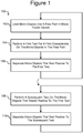
- Figure 1 illustrates an example of a process 100 for testing micro-objects in a microfluidic device according to some embodiments of the invention.
- Figures 2A-2C illustrate an example of a micro fluidic device 200 with which the process 100 can be performed
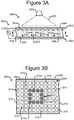
- Figures 3A and 3B illustrate an example of a dielectrophoresis (DEP) device that can be part of the microfluidic device 200.
- Figures 4A-4C illustrate another example of a microfluidic device 400 with which the process 100 can also be performed.
- the device 200 of Figures 2A-2C nor the device 400 of Figures 4A-4C is limited to performing the process 100 of Figure 1 .
- the process 100 limited to being performed on the device 200 or 400.
- the process 100 can load a mixture of micro-objects into a flow path in a microfluidic device at step 102.
- the mixture loaded at step 102 can comprise micro-objects of different types as well as debris and other objects.
- the process 100 can test the micro-objects in the flow path for a first characteristic, and at step 106, the process 100 can separate micro-objects that test positive for the first characteristic from micro-objects that do not test positive (e.g., micro-objects that test negative) for the first characteristic.
- the process 100 can repeat steps 102-106 any number of times.
- steps 102-106 can be performed k times, after which k mixtures of micro-objects have been loaded at step 102 and sorted at steps 104, 106 into an initial group of micro-objects all of which tested positive for the first characteristic.
- the number k can be any integer that is one or greater.
- the process 100 can then proceed to step 108, where the process 100 can perform a subsequent test on the initial group of micro-objects.
- the subsequent test performed at step 108 can be different than the first test performed at step 104.
- the subsequent test can test for a subsequent characteristic that is different than the first characteristic tested at step 104.
- the subsequent test performed at step 108 can test for the same characteristic as step 104 (the first characteristic mentioned above), but the subsequent test can have a different sensitivity, accuracy, precision, or the like.
- the subsequent test performed at step 108 can be more sensitive to the first characteristic than the first test performed at step 104.
- the process 100 can separate the micro-objects that test positive to the subsequent test at step 108 from the micro-objects that test negative to the subsequent test.
- step 104 and the subsequent test of step 108 test for the same characteristic
- steps 108 and 110 micro-objects that tested positive for that characteristic (the first characteristic referred to above in the discussion of step 104) in response to two different tests have been separated from the k mixtures of micro-objects loaded into the microfluidic device at k performances of step 102.
- steps 108 and 110 can be repeated, and at each repetition, the process 100 can apply a different subsequent test at step 108 that tests for the same characteristic.
- steps 108 and 110 can be repeated n times after which the process 100 has sorted from the k mixtures of micro-objects loaded into the microfluidic device at step 102 micro-objects that have tested positive n +1 times for the first characteristic tested at steps 104 and 108.
- the number n can be any integer that is one or greater.
- the process 100 can alternatively test at step 108 for a subsequent characteristic that is different than the first characteristic tested at step 104.
- micro-objects having both the first characteristic and the subsequent characteristic have been sorted from the k mixtures of micro-objects loaded into the microfluidic device at step 102. If steps 108 and 110 are repeated, at each repetition, the process 100 can test for a different subsequent characteristic at step 108.
- the process 100 can test for a subsequent characteristic that is not only different than the first characteristic but also different than any preceding subsequent characteristic tested during any previous pass through steps 108 and 110.
- the process 100 can separate the micro-objects that test positive for the subsequent characteristic at step 108.
- steps 108 and 110 can be repeated n times.
- the process 100 has sorted from the k mixtures of micro-objects loaded into the microfluidic device at step 102 micro-objects that have all n +1 of the characteristics tested at steps 104 and 108.
- the number n can be an integer that is one or greater.
- the repetition of step 108 can sometimes test for a new characteristic not tested at step 104 or any previous performance of step 108 and other times test for the same characteristic tested at step 104 or a previous performance of step 108.
- the process 100 can separate the micro-objects that tested negative from the micro-objects that tested positive.
- the process 100 can repeat step 104 multiple times before proceeding to step 106. In such an example, the process 100 can test for different characteristics at each repetition of step 104 and then separate the micro-objects that tested positive at each repetition of step 104 from micro-objects that tested negative to at least one repetition of step 104.
- step 108 can be repeated multiple times before proceeding to step 110.
- microfluidic devices 200 and 400 are now discussed with respect to Figures 2A-7C .
- Examples of operation of the process 100 with the devices 200 and 400 in which the micro-objects include biological micro-objects such as biological cells are then described with respect to Figures 8-30 .
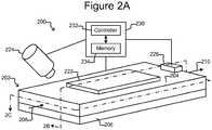
- FIGS 2A-2C illustrate an example of a microfluidic device 200 with which the process 100 can be performed.
- the microfluidic device 200 can comprise a housing 202, a selector 222, a detector 224, a flow controller 226, and a control module 230.
- the housing 202 can comprise one or more flow regions 240 for holding a liquid medium 244.
- Figure 2B illustrates an inner surface 242 of the flow region 240 on which the medium 244 can be disposed as even (e.g., flat) and featureless.
- the inner surface 242, however, can alternatively be uneven (e.g., not flat) and comprise features such as electric terminals (not shown).
- the housing 202 can comprise one or more inlets 208 through which the medium 244 can be input into the flow region 240.
- An inlet 208 can be, for example, an input port, an opening, a valve, another channel, fluidic connectors, or the like.
- the housing 202 can also comprise one or more outlets 210 through which the medium 244 can be removed.
- An outlet 210 can be, for example, an output port, an opening, a valve, a channel, fluidic connectors, or the like.
- the outlet 210 can comprise a droplet outputting mechanism such as any of the outputting mechanisms disclosed in US patent application serial no. 13/856,781 filed April 4, 2013 (attorney docket no. BL1-US). All or part of the housing 202 can be gas permeable to allow gas (e.g., ambient air) to enter and exit the flow region 240.
- gas e.g., ambient air
- the housing 202 can also comprise a microfluidic structure 204 disposed on a base (e.g., a substrate) 206.
- the microfluidic structure 204 can comprise a flexible material, such as rubber, plastic, an elastomer, silicone (e.g., patternable silicone), polydimethylsioxane ("PDMS”), or the like, which can be gas permeable.
- the microfluidic structure 204 can comprise other materials including rigid materials.
- the base 206 can comprise one or more substrates. Although illustrated as a single structure, the base 206 can comprise multiple interconnected structures such as multiple substrates.
- the micro-fluidic structure 104 can likewise comprise multiple structures, which can be interconnected.
- the micro-fluidic structure 104 can additionally comprise a cover (not shown) made from material that is the same as or different than the other material in the structure.
- the microfluidic structure 204 and the base 206 can define the flow region 240. Although one flow region 240 is shown in Figures 2A-2C , the microfluidic structure 204 and the base 206 can define multiple flow regions for the medium 244.
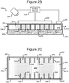
- the flow region 240 can comprise channels (252 in Figure 2C ) and chambers, which can be interconnected to form microfluidic circuits.
- each flow region 240 can be associated with one or more inlets 108 and one or more outlets 110 for respectively inputting and removing medium 144 from the flow region 240.
- the flow region 240 can comprise one or more channels 252 for the medium 244.
- the channel 252 can be generally from the inlet 208 to the outlet 210.
- holding pens 256 defining non-flow spaces can be disposed in the flow region 240. That is, at least a portion of the interior of each holding pen 256 can be a non-flow space into which medium 244 from the channel 252 does not directly flow except when an empty flow region 240 is initially being filled with the medium 244.
- each holding pen 256 can comprise one or more barriers 254 that form a partial enclosure the inside of which can include a non-flow space.
- the barriers 254 that define the holding pens 256 can thus prevent medium 244 from flowing directly into the protected interior of any of the holding pens 256 from the channel 252 while the flow region 240 is filled with medium 244.
- a barrier 254 of a pen 256 can substantially prevent bulk flow of the medium 244 from the channel 252 into the non-flow spaces of the pens 256 while the flow region 240 is filled with medium 244, instead allowing substantially only diffusive mixing of medium from the channel 252 with medium in the non-flow space in a pen 256. Accordingly, exchange of nutrients and waste between the non-flow space in a holding pen 256 and the channel 252 can occur substantially only by diffusion.
- each of the pens 256 substantially impedes direct flow of medium 244 from the channel 252 into the pens 256 because the openings of each of the pens 256 do not face to the left in Figure 2C , which would be directly into such a flow.
- holding pens 256 there can be many such holding pens 256 in the flow region 240 disposed in any pattern, and the holding pens 256 can be any of many different sizes and shapes.
- one or more (including all) of the pens 256 can be stand alone structures disposed away from a sidewall of the microfluidic structure 204 in the channel 252.
- openings of the holding pens 256 can be disposed adjacent the channel 252, which can be adjacent to the openings of more than one pen 256.
- one channel 252 adjacent fourteen pens 256 are shown, there can be more channel 252, and there can be more or fewer pens 256 adjacent any particular channel 252.
- the barriers 254 of the pens 256 can comprise any of the types of materials discussed above with respect to the microfluidic structure 204.
- the barriers 254 can comprise the same material as the microfluidic structure 204 or a different material.
- the barriers 254 can extend from the surface 242 of the base 206 across the entirety of the flow region 240 to an upper wall (opposite the surface 242) of the microfluidic structure 204 as shown in Figure 2B .
- one or more of the barriers 254 can extend only partially across the flow region 240 and thus not extend entirely to the surface 242 or the upper wall of the microfluidic structure 204.
- the selector 222 can be configured to create selectively electrokinetic forces on micro-objects (not shown) in the medium 244.
- the selector 222 can be configured to selectively activate (e.g., turn on) and deactivate (e.g., turn off) electrodes at the inner surface 242 of the flow region 240.
- the electrodes can create forces in the medium 244 that attract or repel micro-objects (not shown) in the medium 244, and the selector 222 can thus select and move one or more micro-objects in the medium 244.
- the electrodes can be, for example, dielectrophoresis (DEP) electrodes.
- the selector 222 can comprise one or more optical (e.g., laser) tweezers devices and/or one or more optoelectronic tweezers (OET) devices (e.g., as disclosed in US Patent No. 7,612,355 or US patent application serial no. 14/051,004 (attorney docket no. BL9-US).
- the selector 222 can include one or more devices (not shown) for moving a droplet of the medium 244 in which one or more of micro-objects are suspended.
- Such devices (not shown) can include electrowetting devices such as optoelectronic wetting (OEW) devices (e.g., as disclosed in US Patent No. 6,958,132 ).
- the selector 222 can thus be characterized as a DEP device in some embodiments.
- Figures 3A and 3B illustrate an example in which the selector 222 comprises a DEP device 300.
- the DEP device 300 can comprise a first electrode 304, a second electrode 310, an electrode activation substrate 308, a power source 312 (e.g., an alternating current (AC) power source), and a light source 320.
- a power source 312 e.g., an alternating current (AC) power source
- Medium 244 in the flow region 240 and the electrode activation substrate 308 can separate the electrodes 304, 310.
- Changing patterns of light 322 from the light source 320 can selectively activate and deactivate changing patterns of DEP electrodes at regions 314 of the inner surface 242 of the flow region 240. (Hereinafter the regions 314 are referred to as "electrode regions.”)
- a light pattern 322' directed onto the inner surface 242 illuminates the cross-hatched electrode regions 314a in the square pattern shown.
- the other electrode regions 314 are not illuminated and are hereinafter referred to as "dark" electrode regions 314.
- the relative electrical impedance across the electrode activation substrate 308 from each dark electrode region 314 to the second electrode 310 is greater than the relative impedance from the first electrode 304 across the medium 244 in the flow region 240 to the dark electrode region 314.
- Illuminating an electrode region 314a reduces the relative impedance across the electrode activation substrate 308 from the illuminated electrode region 314a to the second electrode 310 to less than the relative impedance from the first electrode 304 across the medium 244 in the flow region 240 to the illuminated electrode region 314a.
- DEP electrodes that attract or repel micro-objects in the medium 244 can thus be selectively activated and deactivated at many different such electrode regions 314 at the inner surface 242 of the flow region 240 by changing light patterns 322 projected form a light source 320 (e.g., a laser source or other type of light source) into the microfluidic device 200. Whether the DEP forces attract or repel nearby micro-objects can depend on such parameters as the frequency of the power source 312 and the dielectric properties of the medium 244 and/or micro-objects (not shown).
- the square pattern 322' of illuminated electrode regions 314a illustrated in Figure 3B is an example only. Any pattern of the electrode regions 314 can be illuminated by the pattern of light 322 projected into the device 200, and the pattern of illuminated electrode regions 322' can be repeatedly changed by changing the light pattern 322.
- the electrode activation substrate 308 can be a photoconductive material, and the inner surface 242 can be featureless.
- the DEP electrodes 314 can be created anywhere and in any pattern on the inner surface 242 of the flow region 240 in accordance with the light pattern 322 (see Figure 3A ). The number and pattern of the electrode regions 314 are thus not fixed but correspond to the light pattern 322. Examples are illustrated in the aforementioned US Patent No. 7,612,355 , in which the un-doped amorphous silicon material 24 shown in the drawings of the foregoing patent can be an example of photoconductive material that can compose the electrode activation substrate 308.
- the electrode activation substrate 308 can comprise a circuit substrate such as a semiconductor material comprising a plurality of doped layers, electrically insulating layers, and electrically conductive layers that form semiconductor integrated circuits such as is known in semiconductor fields.
- electric circuit elements can form electrical connections between the electrode regions 314 at the inner surface 242 of the flow region 240 and the second electrode 310 that can be selectively activated and deactivated by the light pattern 322.
- each electrical connection can have high impedance such that the relative impedance from a corresponding electrode region 214 to the second electrode 210 is greater than the relative impedance from the first electrode 204 through the medium 144 to the corresponding electrode region 214.
- each electrical connection can have low impedance such that the relative impedance from a corresponding electrode region 214 to the second electrode 210 is less than the relative impedance from the first electrode 204 through the medium 144 to the corresponding electrode region 214, which activates a DEP electrode at the corresponding electrode region 214 as discussed above.
- DEP electrodes that attract or repel micro-objects (not shown) in the medium 144 can thus be selectively activated and deactivated at many different electrode regions 214 at the inner surface 142 of the flow region 140 by the light pattern 222.
- Non-limiting examples of such configurations of the electrode activation substrate 308 include the phototransistor-based device 300 illustrated in Figures 21 and 22 of US Patent No. 7,956,339 and the devices 200, 400, 500, and 600 illustrated throughout the drawings in the aforementioned US patent application serial no. 14/051,004 .
- the first electrode 304 can be part of a first wall 302 (or cover) of the housing 202, and the electrode activation substrate 308 and second electrode 310 can be part of a second wall 306 (or base) of the housing 202, generally as illustrated in Figure 3A .
- the flow region 240 can be between the first wall 302 and the second wall 306.
- the first electrode 304 can be part of the second wall 306 and one or both of the electrode activation substrate 308 and/or the second electrode 310 can be part of the first wall 302.
- the first electrode 304 can be part of the same wall 302 or 306 as the electrode activation substrate 308 and the second electrode 310.
- the electrode activation substrate 308 can comprise the first electrode 304 and/or the second electrode 310.
- the light source 320 can alternatively be located below the housing 202.
- the selector 222 can thus select a micro-object (not shown) in the medium 244 in the flow region 240 by projecting a light pattern 322 into the device 200 to activate one or more DEP electrodes at electrode regions 314 of the inner surface 242 of the flow region 240 in a pattern that surrounds and captures the micro-object.
- the selector 222 can then move the captured micro-object by moving the light pattern 322 relative to the device 200.
- the device 200 can be moved relative to the light pattern 322.
- barriers 254 that define the holding pens 256 are illustrated in Figures 2B and 2C and discussed above as physical barriers, the barriers 254 can alternatively be virtual barriers comprising DEP forces activated by light in the light pattern 322.
- the detector 224 can be a mechanism for detecting events in the flow region 240.
- the detector 224 can comprise a photodetector capable of detecting one or more radiation characteristics (e.g., due to fluorescence or luminescence) of a micro-object (not shown) in the medium.
- a detector 224 can be configured to detect, for example, that one or more micro-objects (not shown) in the medium 244 are radiating electromagnetic radiation and/or the approximate wavelength, brightness, intensity, or the like of the radiation.
- suitable photodetectors include without limitation photomultiplier tube detectors and avalanche photodetectors.
- the detector 224 can alternatively or in addition comprise an imaging device for capturing digital images of the flow region 240 including micro-objects (not shown) in the medium 244.
- imaging devices that the detector 224 can comprise include digital cameras or photosensors such as charge coupled devices and complementary metal-oxide-semiconductor imagers. Images can be captured with such devices and analyzed (e.g., by the control module 230 and/or a human operator).
- the flow controller 226 can be configured to control a flow of the medium 244 in the flow region 240.
- the flow controller 226 can control the direction and/or velocity of the flow.
- Non-limiting examples of the flow controller 226 include one or more pumps or fluid actuators.
- the flow controller 226 can include additional elements such as one or more sensors (not shown) for sensing, for example, the velocity of the flow of the medium 244 in the flow region 240.
- the control module 230 can be configured to receive signals from and control the selector 222, the detector 224, and/or the flow controller 226. As shown, the control module 230 can comprise a controller 232 and a memory 234.
- the controller 232 can be a digital electronic controller (e.g., a microprocessor, microcontroller, computer, or the like) configured to operate in accordance with machine readable instructions (e.g., software, firmware, microcode, or the like) stored as non-transitory signals in the memory 234, which can be a digital electronic, optical, or magnetic memory device.
- the controller 232 can comprise hardwired digital circuitry and/or analog circuitry or a combination of a digital electronic controller operating in accordance with machine readable instructions and hardwired digital circuitry and/or analog circuitry.
- the controller 130 can be configured to perform all or any part of the processes 100, 400 disclosed herein.
- the pens 256 can be shielded from illumination (e.g., by the detector 224 and/or the selector 222) or can be only selectively illuminated for brief periods of time. Biological micro-objects 502 can thus be protected from further illumination or further illumination of the biological micro-objects 502 can be minimized after the biological micro-objects 502 are moved into the pens 256.
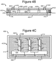
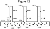
- FIGS 4A-4C illustrate another example of a microfluidic device 400.
- the microfluidic device 400 can enclose a microfluidic circuit 432 comprising a plurality of interconnected fluidic circuit elements.
- the microfluidic circuit 432 includes a flow region/channel 434 to which sequestration pens 436, 438, 440 are fluidically connected.
- One channel 434 and three sequestration pens 436, 438, 440 are shown, but there can be more than one channel 434 and more or fewer than three sequestration pens 436, 438, 440 connected with any particular channel.
- the channel 434 and sequestration pens 436, 438, 440 are examples of fluidic circuit elements.
- the microfluidic circuit 432 can also include additional or different fluidic circuit elements such as fluidic chambers, reservoirs, and the like.
- Each sequestration pen 436, 438, 440 can comprise an isolation structure 446 defining an isolation region 444 and a connection region 442 fluidically connecting the isolation region 444 to the channel 434.
- the connection region 442 can comprise a proximal opening 452 to the channel 434 and a distal opening 454 to the isolation region 444.
- the connection region 442 can be configured so that a maximum penetration depth of a flow of a fluidic medium (not shown) flowing at a maximum velocity (V max ) in the channel 434 does not extend into the isolation region 444.
- a micro-object (not shown) or other material (not shown) disposed in an isolation region 444 of a pen 436, 438, 440 can thus be isolated from and not substantially affected by a flow of medium (not shown) in the channel 434.
- the channel 434 can thus be an example of a swept region, and the isolation regions of the sequestration pens 436, 438, 440 can be examples of unswept regions.
- the microfluidic device 400 can comprise an enclosure 402 enclosing the microfluidic circuit 432, which can contain one or more fluidic media.
- the enclosure 402 is depicted as comprising a support structure 404 (e.g., a base), a microfluidic circuit structure 412, and a cover 422.
- the support structure 404, microfluidic circuit structure 412, and the cover 422 can be attached to each other.
- the microfluidic circuit structure 412 can be disposed on the support structure 404, and the cover 422 can be disposed over the microfluidic circuit structure 412.
- the microfluidic circuit structure 412 can define the microfluidic circuit 432.
- An inner surface of the microfluidic circuit 432 is identified in the figures as 406.
- the support structure 404 can be at the bottom and the cover 422 at the top of the device 400 as illustrated in Figures 4A and 4B .
- the support structure 404 and cover 422 can be in other orientations.
- the support structure 404 can be at the top and the cover 422 at the bottom of the device 400.
- the microfluidic circuit structure 412 can define circuit elements of the microfluidic circuit 432 or circuits in the enclosure 402.
- the microfluidic circuit structure 412 comprises a frame 414 and a microfluidic circuit material 416.
- the support structure 404 can comprise a substrate or a plurality of interconnected substrates.
- the support structure 404 can comprise one or more interconnected semiconductor substrates, printed circuit boards, or the like.
- the frame 414 can partially or completely enclose the microfluidic circuit material 416.
- the frame 414 can be, for example, a relatively rigid structure substantially surrounding the microfluidic circuit material 416.
- the frame 414 can comprise a metal material.
- the microfluidic circuit material 416 can be patterned with cavities or the like to define microfluidic circuit elements and interconnections of the microfluidic circuit 432.
- the microfluidic circuit material 416 can comprise a flexible material, such as rubber, plastic, elastomer, silicone (e.g., patternable silicone), PDMS, or the like, which can be gas permeable.
- Other examples of materials that can compose microfluidic circuit material 416 include molded glass, an etchable material such as silicon, photo-resist (e.g., SU8), or the like. In some embodiments, such materials-and thus the microfluidic circuit material 416-can be rigid and/or substantially impermeable to gas.
- microfluidic circuit material 416 can be disposed on the support structure 404 and inside the frame 414.
- the cover 422 can be an integral part of the frame 414 and/or the microfluidic circuit material 416.
- the cover 422 can be a structurally distinct element (as illustrated in Figures 4A and 4B ).
- the cover 422 can comprise the same or different materials than the frame 414 and/or the microfluidic circuit material 416.
- the support structure 404 can be a separate structure from the frame 414 or microfluidic circuit material 416 as illustrated or an integral part of the frame 414 or microfluidic circuit material 416.
- the frame 414 and microfluidic circuit material 416 can be separate structures as shown in Figures 4A-4C or integral portions of the same structure.
- the cover 422 and/or the support structure 404 can be transparent to light.
- Figure 4A also illustrates simplified block diagram depictions of examples of a control/monitoring system 470 that can be utilized in conjunction with the microfluidic device 400.
- the system 470 can comprise a control module 472 and control/monitoring equipment 480.
- the control module 472 can be configured to control and monitor the device 400 directly and/or through the control/monitoring equipment 480.
- the control module 472 can comprise a digital controller 474 and a digital memory 476.
- the controller 474 can be, for example, a digital processor, computer, or the like, and the digital memory 476 can be a non-transitory digital memory for storing data and machine executable instructions (e.g., software, firmware, microcode, or the like) as non-transitory data or signals.
- the controller 474 can be configured to operate in accordance with such machine executable instructions stored in the memory 476.
- the controller 474 can comprise hardwired digital circuitry and/or analog circuitry.
- the control module 472 can thus be configured to perform all or part of any process (e.g., process 100 of Figure 1 and/or process 2500 of Figure 25 ), step of such a process, function, act, or the like discussed herein.
- the control/monitoring equipment 480 can comprise any of a number of different types of devices for controlling or monitoring the microfluidic device 400 and processes performed with the microfluidic device 400.
- the equipment 480 can include power sources (not shown) for providing power to the microfluidic device 400; fluidic media sources (not shown but can comprise a flow controller like 226 of Figure 2A ) for providing fluidic media to or removing media from the microfluidic device 400; motive modules (not shown but can comprise a selector like 222 of Figure 2A ) for controlling selection and movement of micro-objects (not shown) in the microfluidic circuit 432; image capture mechanisms (not shown but can be like the detector 224 of Figure 2A ) for capturing images (e.g., of micro-objects) inside the microfluidic circuit 432; stimulation mechanisms (not shown) for directing energy into the microfluidic circuit 432 to stimulate reactions; or the like.
- control/monitoring equipment 480 can comprise motive modules for selecting and moving micro-objects (not shown) in the microfluidic circuit 432.
- motive mechanisms can be utilized.
- DEP dielectrophoresis
- the base 404 and/or cover 422 of the microfluidic device 400 can comprise DEP configurations for selectively inducing DEP forces on micro-objects (not shown) in a fluidic medium (not shown) in the microfluidic circuit 432 to select, capture, and/or move individual micro-objects.
- the control/monitoring equipment 480 can include one or more control modules for such DEP configurations.
- An example of such a DEP configuration of the support structure 404 or the cover 422 is an optoelectronic tweezers (OET) configuration.
- OET optoelectronic tweezers
- Examples of suitable OET configurations of the support structure 404 or cover 422 and associated monitoring and control equipment are illustrated in the following U.S. patent documents U.S. Patent No. 7,612,355 ; U.S. Patent No. 7,956,339 ; U.S. Patent Application Publication No. 2012/0325665 ; U.S. Patent Application Publication No. 2014/0124370 ; U.S. patent application serial no. 14/262,140 (pending); and U.S. patent application serial no. 14/262,200 (pending).
- Micro-objects can thus be individually selected, captured, and moved within the microfluidic circuit 432 of the microfluidic device 400 utilizing DEP devices and techniques such as OET.
- the channel 434 and pens 436, 438, 440 can be configured to contain one or more fluidic media (not shown).
- ports 424 are connected to the channel 434 and allow a fluidic medium (not shown) to be introduced into or removed from the microfluidic circuit 432. Once the microfluidic circuit 432 contains the fluidic medium (not shown), flows of fluidic media (not shown) can be selectively generated and stopped in the channel 434.
- ports 424 can be disposed at different locations (e.g., opposite ends) of the channel 434, and a flow of medium (not shown) can be created from one port 424 functioning as an inlet to another port 424 functioning as an outlet.
- each sequestration pen 436, 438, 440 can comprise a connection region 442 and an isolation region 444.
- the connection region 442 can comprise a proximal opening 452 to the channel 434 and a distal opening 454 to the isolation region 444.
- the channel 434 and each sequestration pen 436, 438, 440 can be configured so that the maximum penetration depth of a flow of medium (not shown) flowing in the channel 434 extends into the connection region 442 but not the isolation region 444.
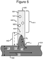
- Figure 5 illustrates a detailed view of an example of a sequestration pen 436.
- Pens 438, 440 can be configured similarly.
- Examples of micro-objects 522 in pen 436 are also shown.
- a flow 512 of fluidic medium 502 in a microfluidic channel 434 past a proximal opening 452 of a pen 436 can cause a secondary flow 514 of the medium 502 into and/or out of the pen.
- the length L con of the connection region 442 of the sequestration pen 436 from the proximal opening 452 to the distal opening 454 can be greater than a maximum penetration depth D p of the secondary flow 514 into the connection region 442 when the velocity of the flow 512 in the channel 434 is at a maximum (V max ).
- V max maximum penetration depth
- the flow 512 and resulting secondary flow 514 can thus be limited to the channel 434 and the connection region 442 and kept out of the isolation region 444.
- the flow 512 in the channel 434 will thus not draw micro-objects 522 out of the isolation region 444.
- Micro-objects 522 in the isolation region 444 will thus stay in the isolation region 444 regardless of the flow 512 in the channel 432.
- the flow 512 will not move miscellaneous particles (e.g., microparticles and/or nanoparticles) from the channel 434 into the isolation region 444 of a pen 436, nor will the flow 512 draw miscellaneous particles from the isolation region 444 into the channel 434.
- miscellaneous particles e.g., microparticles and/or nanoparticles
- Having the length L con of the connection region 442 be greater than the maximum penetration depth D p can thus prevent contamination of one pen 436 with miscellaneous particles from the channel 434 or another pen 438, 440.
- the channel 434 and the connection regions 442 of the pens 436, 438, 440 can be affected by the flow 512 of medium 502 in the channel 434, the channel 434 and connection regions 442 can be deemed swept (or flow) regions of the microfluidic circuit 432.
- the isolation regions 444 of the pens 436, 438, 440 can be deemed unswept (or non-flow) regions.
- a first medium 502 (e.g., components (not shown) in the first medium 502) in the channel 434 can mix with a second medium 504 (e.g., components (not shown) in the second medium 504) in the isolation region 444 substantially only by diffusion of the first medium 504 from the channel 434 through the connection region 442 and into the second medium 504 in the isolation region 444.
- a second medium 504 e.g., components (not shown) in the second medium 504
- the second medium 504 (e.g., components (not shown) in the second medium 504) in the isolation region 444 can mix with the first medium 504 (e.g., components (not shown) in the first medium 502) in the channel 434 substantially only by diffusion of the second medium 502 from the isolation region 444 through the connection region 442 and into the first medium 502 in the channel 434.
- the first medium 502 can be the same medium or a different medium than the second medium 504.
- the first medium 502 and the second medium 504 can start out being the same, then become different (e.g., through conditioning of the second medium by one or more biological micro-objects in the isolation region 444, or by changing the medium flowing through the channel 434).
- the maximum penetration depth D p of the secondary flow 514 caused by the flow 512 in the channel 434 can depend on a number of parameters. Examples of such parameters include: the shape of the channel 434 (e.g., the channel can direct medium into the connection region 442, divert medium away from the connection region 442, or simply flow past the connection region 442); a width W ch (or cross-sectional area) of the channel 434 at the proximal opening 452; a width W con (or cross-sectional area) of the connection region 442 at the proximal opening 452; the maximum velocity V max of the flow 512 in the channel 434; the viscosity of the first medium 502 and/or the second medium 504, or the like.
- the shape of the channel 434 e.g., the channel can direct medium into the connection region 442, divert medium away from the connection region 442, or simply flow past the connection region 442
- the dimensions of the channel 434 and sequestration pens 436, 438, 440 can be oriented as follows with respect to the flow 512 in the channel 434: the channel width W ch (or cross-sectional area of the channel 434) can be substantially perpendicular to the flow 512, the width W con (or cross-sectional area) of the connection region 442 at the proximal opening 552 can be substantially parallel to the flow 512, and the length L con of the connection region can be substantially perpendicular to the flow 512.
- the dimensions of the channel 434 and sequestration pens 436, 438, 440 can be in other orientations with respect to each other.
- the width W ch of the channel 434 at a proximal opening 452 can be within any of the following ranges: 50-1000 microns, 50-500 microns, 50-400 microns, 50-300 microns, 50-250 microns, 50-200 microns, 50-150 microns, 50-100 microns, 70-500 microns, 70-400 microns, 70-300 microns, 70-250 microns, 70-200 microns, 70-150 microns, 90-400 microns, 90-300 microns, 90-250 microns, 90-200 microns, 90-150 microns, 100-300 microns, 100-250 microns, 100-200 microns, 100-150 microns, and 100-120 microns.
- the foregoing are examples only, and the width W ch of the channel 434 can be in other ranges (e.g., a range defined by any of the endpoints listed above).
- the height H ch of the channel 134 at a proximal opening 152 can be within any of the following ranges: 20-100 microns, 20-90 microns, 20-80 microns, 20-70 microns, 20-60 microns, 20-50 microns, 30-100 microns, 30-90 microns, 30-80 microns, 30-70 microns, 30-60 microns, 30-50 microns, 40-100 microns, 40-90 microns, 40-80 microns, 40-70 microns, 40-60 microns, or 40-50 microns.
- the foregoing are examples only, and the height H ch of the channel 434 can be in other ranges (e.g., a range defined by any of the endpoints listed above).
- a cross-sectional area of the channel 434 at a proximal opening 452 can be within any of the following ranges: 500-50,000 square microns, 500-40,000 square microns, 500-30,000 square microns, 500-25,000 square microns, 500-20,000 square microns, 500-15,000 square microns, 500-10,000 square microns, 500-7,500 square microns, 500-5,000 square microns, 1,000-25,000 square microns, 1,000-20,000 square microns, 1,000-15,000 square microns, 1,000-10,000 square microns, 1,000-7,500 square microns, 1,000-5,000 square microns, 2,000-20,000 square microns, 2,000-15,000 square microns, 2,000-10,000 square microns, 2,000-7,500 square microns, 2,000-6,000 square microns, 3,000-20,000 square microns, 3,000-15,000 square microns, 3,000-10,000 square microns, 3,000-7,500 square microns, or 3,000 to 6,000 square microns.
- the length of the connection region L con can be in any of the following ranges: 1-200 microns, 5-150 microns, 10-100 microns, 15-80 microns, 20-60 microns, 20-500 microns, 40-400 microns, 60-300 microns, 80-200 microns, and 100-150 microns.
- the foregoing are examples only, and length L con of a connection region 442 can be in a different ranges than the foregoing examples (e.g., a range defined by any of the endpoints listed above).
- the width W con of a connection region 442 at a proximal opening 452 can be in any of the following ranges: 20-500 microns, 20-400 microns, 20-300 microns, 20-200 microns, 20-150 microns, 20-100 microns, 20-80 microns, 20-60 microns, 30-400 microns, 30-300 microns, 30-200 microns, 30-150 microns, 30-100 microns, 30-80 microns, 30-60 microns, 40-300 microns, 40-200 microns, 40-150 microns, 40-100 microns, 40-80 microns, 40-60 microns, 50-250 microns, 50-200 microns, 50-150 microns, 50-100 microns, 50-80 microns, 60-200 microns, 60-150 microns, 60-100 microns, 60-80 microns, 70-150 microns, 70-100 microns, and 80-100
- the width W con of a connection region 442 at a proximal opening 452 can be in any of the following ranges: 2-35 microns, 2-25 microns, 2-20 microns, 2-15 microns, 2-10 microns, 2-7 microns, 2-5 microns, 2-3 microns, 3-25 microns, 3-20 microns, 3-15 microns, 3-10 microns, 3-7 microns, 3-5 microns, 3-4 microns, 4-20 microns, 4-15 microns, 4-10 microns, 4-7 microns, 4-5 microns, 5-15 microns, 5-10 microns, 5-7 microns, 6-15 microns, 6-10 microns, 6-7 microns, 7-15 microns, 7-10 microns, 8-15 microns, and 8-10 microns.
- the foregoing are examples only, and the width W con of a connection region 442 at a proximal opening 452 can be different than the foregoing examples
- a ratio of the length L con of a connection region 442 to a width W con of the connection region 442 at the proximal opening 452 of can be greater than or equal to any of the following ratios: 0.5, 1.0, 1.5, 2.0, 2.5, 3.0, 3.5, 4.0, 4.5, 5.0, 6.0, 7.0, 8.0, 9.0, 10.0, or more.
- ratios 0.5, 1.0, 1.5, 2.0, 2.5, 3.0, 3.5, 4.0, 4.5, 5.0, 6.0, 7.0, 8.0, 9.0, 10.0, or more.
- the foregoing are examples only, and the ratio of the length L con of a connection region 442 to a width W con of the connection region 442 at the proximal opening 452 can be different than the foregoing examples.
- the width W con of the connection region 442 can be uniform from the proximal opening 452 to the distal opening 454.
- the width W con of the connection region 442 at the distal opening 454 can thus be in any of the ranges identified above for the width W con of the connection region 442 at the proximal opening 452.
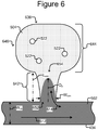
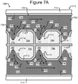
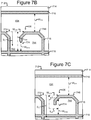
- the width W con of the connection region 442 at the distal opening 454 can be larger (e.g., as shown in Figure 6 ) or smaller (e.g., as shown in Figures 7A-7C ) than the width W con of the connection region 442 at the proximal opening 452.
- the width of the isolation region 444 at the distal opening 454 can be substantially the same as the width W con of the connection region 442 at the proximal opening 452.
- the width of the isolation region 444 at the distal opening 454 can thus be in any of the ranges identified above for the width W con of the connection region 442 at the proximal opening 452.
- the width of the isolation region 444 at the distal opening 454 can be larger (e.g., as shown in Figure 6 ) or smaller (not shown) than the width W con of the connection region 442 at the proximal opening 452.
- the maximum velocity V max of a flow 512 in the channel 434 is the maximum velocity that the channel can maintain without causing a structural failure in the microfluidic device in which the channel is located.
- the maximum velocity that a channel can maintain depends on various factors, including the structural integrity of the microfluidic device and the cross-sectional area of the channel.
- the maximum flow velocity V max in a channel having a cross-sectional area of around 3,000 to 4,000 square microns is around 10 ⁇ L/sec.
- the maximum velocity V max of a flow 512 in channel 434 can be set so as to ensure that isolation regions 444 are isolated from the flow 512 in channel 434.
- V max can be set so as to ensure that the depth of penetration D p of a secondary flow 514 into the connection region is less than L con .
- V max can be set around 0.2, 0.3, 0.4, 0.5, 0.6, 0.7, 0.8, 0.9, 1.0, 1.1, 1.2, 1.3, 1.4, or 1.5 ⁇ L/sec.
- the sum of the length L con of the connection region 442 and a corresponding length of the isolation region 444 of a sequestration pen 436, 438, 440 can be sufficiently short for relatively rapid diffusion of components of a second medium 504 in the isolation region 444 to a first medium 502 in the channel 434.
- the sum of (1) the length L con of the connection region 442 and (2) the distance between a biological micro-object located in isolation region 444 of a sequestration pen 436, 438, 440 and the distal opening 454 of the connection region can be in the following ranges: 40 microns to 300 microns, 50 microns to 550 microns, 60 microns to 500 microns, 70 microns to 180 microns, 80 microns to 160 microns, 90 microns to 140 microns, 100 microns to 120 microns, or any range including one of the foregoing end points.
- the rate of diffusion of a molecule is dependent on a number of factors, including temperature, viscosity of the medium, and the coefficient of diffusion D 0 of the molecule.
- the D 0 for an IgG antibody in aqueous solution at 20°C is around 4.4x10 -7 cm 2 /sec, while the viscosity of biological micro-object culture medium is around 9x10⁻⁴ m2/sec.
- an antibody in biological micro-object culture medium at 20°C can have a rate of diffusion of around 0.5 microns/sec.
- a time period for diffusion from a biological micro-object located in isolation region 444 into the channel 434 can be about 10 minutes or less (e.g., 9, 8, 7, 6, 5 minutes, or less).
- the time period for diffusion can be manipulated by changing parameters that influence the rate of diffusion. For example, the temperature of the media can be increased (e.g., to a physiological temperature such as 37°C) or decreased (e.g., to 15°C, 10°C, or 4°C) thereby increasing or decreasing the rate of diffusion, respectively.
- the configuration of sequestration pen 436 illustrated in Figure 5 is but an example, and many variations are possible.
- the isolation region 444 is illustrated as sized to contain a plurality of micro-objects 522, but the isolation region 444 can be sized to contain only one, two, three, four, five, or similar relatively small numbers of micro-objects 522.
- the volume of an isolation region 444 can be, for example, at least 3x10 3 , 6x10 3 , 9x10 3 , 1x10 4 , 2x10 4 , 4x10 4 , 8x10 4 , 1x10 5 , 2x10 5 , 4x10 5 , 8x10 5 , 1x10 6 , 2x10 6 cubic microns, or more.
- the sequestration pen 436 is shown extending generally perpendicularly from the channel 434 and thus forming generally 90 ° angles with the channel 434.
- the sequestration pen 436 can alternatively extend from the channel 434 at other angles such as, for example, any angle between 30° and 150°.
- connection region 442 and the isolation region 444 are illustrated in Figure 5 as substantially rectangular, but one or both of the connection region 442 and the isolation region 444 can be other shapes. Examples of such shapes include oval, triangular, circular, hourglass-shaped, and the like.
- connection region 442 and the isolation region 444 are illustrated in Figure 5 as having substantially uniform widths. That is, in Figure 5 , the width W con of the connection region 442 is shown as being uniform from the proximal opening 452 to the distal opening 454; a corresponding width of the isolation region 444 is similarly uniform; and the width W con of the connection region 442 and a corresponding width of the isolation region 444 are shown as equal. Any of the foregoing can be different than shown in Figure 5 .
- a width W con of the connection region 442 can vary from the proximal opening 452 to the distal opening 554 (e.g., in the manner of a trapezoid or an hourglass); a width of the isolation region 444 can vary (e.g., in the manner of a triangle or flask); and a width W con of the connection region 442 can be different than a corresponding width of the isolation region 444.
- Figure 6 illustrates an example of a sequestration pen illustrating examples of some of the foregoing variations.
- the pen shown in Figure 6 can replace any of pens 436, 438, 440 in any of the figures or discussions herein.
- the sequestration pen of Figure 6 can comprise a connection region 642 and an isolation structure 646 comprising an isolation region 644.
- the connection region 642 can comprise a proximal opening 652 to the channel 434 and a distal opening 654 to the isolation region 644.
- the connection region 642 expands such that its width W con increases from the proximal opening 652 to the distal opening 654.
- the connection region 642, isolation structure 646, and isolation region 644 can be generally the same as the connection region 442, isolation structure 446, and isolation region 444 of Figure 5 as discussed above.
- the channel 434 and the sequestration pen of Figure 6 can be configured so that the maximum penetration depth D p of the secondary flow 514 extends into the connection region 642 but not into the isolation region 644.
- the length L con of the connection region 642 can thus be greater than the maximum penetration depth D p , generally as discussed above with respect to Figure 5 .
- micro-objects 522 in the isolation region 644 will thus stay in the isolation region 644 as long as the velocity of the flow 512 in the channel 434 does not exceed the maximum flow velocity V max .
- the channel 434 and connection region 642 are thus examples of swept (or flow) regions, and the isolation region 644 is an example of an unswept (or non-flow) region.
- Figures 7A-7C show examples of variations of the microfluidic circuit 432 and channel 434 of Figures 4A-4C , as well as additional examples of variations of sequestration pens 436, 438, 440.
- the sequestration pens 736 shown in Figures 7A-7C can replace any of the pens 436, 438, 440 in any of the figures or discussions herein.
- the microfluidic device 700 can replace the microfluidic device 400 in any of the figures or discussions herein.
- the microfluidic device 700 of Figures 7A-7C can comprise a support structure (not visible but can be like 404 of Figure 4A-4C ), a microfluidic circuit structure 712, and a cover (not visible but can be like 422).
- the microfluidic circuit structure 712 can comprise a frame 714 and microfluidic circuit material 716, which can be the same as or generally similar to the frame 414 and microfluidic circuit material 416 of Figures 4A-4C .
- the microfluidic circuit 732 defined by the microfluidic circuit material 716 can comprise multiple channels 734 (two are shown but there can be more) to which multiple sequestration pens 736 are fluidically connected.
- Each sequestration pen 736 can comprise an isolation structure 746, an isolation region 744 within the isolation structure 746, and a connection region 742. From a proximal opening 772 at the channel 734 to a distal opening 774 at the isolation structure 736, the connection region 742 can fluidically connect the channel 734 to the isolation region 744.
- a flow 782 of a first fluidic medium 702 in a channel 734 can create secondary flows 784 of the first medium 702 from the channel 734 into and/or out of the connection regions 742 of pens 736 that are connected to the channel 734.
- connection region 742 can include the area between the proximal opening 772 to a channel 734 and the distal opening 774 to an isolation structure 746.
- the length L con of the connection region 742 can be greater than the maximum penetration depth D p of secondary flow 784, in which case the secondary flow 784 will extend into the connection region 742 without being redirected toward the isolation region 744 (as shown in Figure 7A ).
- the connection region 742 can have a length L con that is less than the maximum penetration depth D p , in which case the secondary flow 784 will extend through the connection region 742 and can be redirected toward the isolation region 744.
- connection region 742 can be greater than the maximum penetration depth D p .
- secondary flow 784 will not extend into isolation region 744.
- a flow 782 of a first medium 702 in channel 734 that does not exceed a maximum velocity V max will produce a secondary flow having a penetration depth D p
- micro-objects (not shown but can be like 522 in Figure 5 ) in the isolation region 744 of a pen 736 will not be drawn out of the isolation region 744 by a flow 782 of first medium 702 in a channel 734.
- the flow 782 in the channel 734 draw miscellaneous materials (not shown) from a channel 734 into the isolation region 744 of a pen 736 or from the isolation region 744 into the channel 734.
- Diffusion is the only mechanism by which components in a first medium 702 in the channel 734 can move from the channel 734 into a second medium 704 in an isolation region 744 of a pen 736.
- diffusion is the only mechanism by which components in a second medium 704 in an isolation region 744 of a pen 736 can move from the isolation region 744 to a first medium 702 in the channel 734.
- the first medium 702 can be the same medium as the second medium 704, or the first medium 702 can be a different medium than the second medium 704.
- first medium 702 and the second medium 704 can start out being the same, then become different (e.g., through conditioning of the second medium by one or more biological micro-objects in the isolation region 744, or by changing the medium flowing through the channel 734).
- the width W ch of a channel 734 perpendicular to the direction of a flow 782 (see Figure 7A ) in the channel 734 can be substantially perpendicular to a width W con1 of the proximal opening 772 and thus substantially parallel to a width W con2 of the distal opening 774.
- the width W con1 of the proximal opening 772 and the width W con2 of the distal opening 774 need not be substantially perpendicular to each other.
- an angle between an axis (not shown) on which the width W con1 of the proximal opening 772 is oriented and another axis on which the width W con2 of the distal opening 774 is oriented can be other than perpendicular and thus other than 90°.
- angles include angles in any of the following ranges: between 30° and 90°, between 45° and 90°, between 60° and 90°, or the like.
- a fluidic medium e.g., a first medium and/or a second medium
- a fluidic medium can be any fluid that is capable of maintaining a biological micro-object in a substantially assayable state.
- the assayable state will depend on the biological micro-object and the assay being performed. For example, if the biological micro-object is a biological micro-object that is being assayed for the secretion of a protein of interest, the biological micro-object would be substantially assayable provided that it is viable and capable of expressing and secreting proteins.
- FIGs 8-30 illustrate examples of the process 100 of Figure 1 testing biological micro-objects (e.g., biological cells) in the microfluidic device 200 of Figures 2A-2C or the microfluidic device 400 of Figures 4A-4C .
- the process 100 is not, however, limited to sorting biological micro-objects or operating on the microfluidic devices 200, 400.
- the microfluidic devices 200, 400 limited to performing the process 100.
- aspects of the steps of process 100 may be discussed in connection with device 200 but not device 400, or vice versa, such aspects can be applied in the other device or any other similar micro-fluidic devices.
- the process 100 can load biological micro-objects into a micro-fluidic device.
- Figure 8 illustrates an example in which biological micro-objects 802 (e.g., biological cells) are loaded into a flow region 240 (e.g., the channel 252) of the microfluidic device 200.
- Figure 9 shows an example in which sample material 902 comprising biological micro-objects 904 is flowed into a channel 434 of the microfluidic device 400.
- a mixture of biological micro-objects 802 can be loaded into the channel 252 of the microfluidic device 200.
- the biological micro-objects 802 can be input into the device 200 through the inlet 208 (see Figures 2A-2C ), and the biological micro-objects 802 can move with a flow 804 of medium 244 in the channel 252.
- the flow 804 can be a convection flow.
- the flow 804 can be stopped or slowed to keep the biological micro-objects 802 in the flow channel 252 adjacent to the pens 256 for a time sufficient to perform steps 104 and 106.
- the mixture of biological micro-objects 802 loaded in the channel 252 can comprise different types of biological micro-objects and other components such as debris, proteins, contamination, particles, and the like.
- Figure 9 illustrates an example in which sample material 902 comprising biological micro-objects 904 is flowed into a channel 434 of the microfluidic device 400.
- the sample material 902 can comprise other micro-objects (not shown) or materials (not shown).
- the channel 434 can have a cross-sectional area disclosed herein, e.g., about 3,000 to 6,000 square microns or about 2,500 to 4,000 square microns.
- the sample material 902 can be flowed into the channel 434 at a rate disclosed herein, e.g., about 0.05 to 0.25 ⁇ L/sec (e.g., about 0.1 to 0.2 ⁇ L/sec or about 0.14 to 0.15 ⁇ L/sec).
- the control module 472 of Figure 4A can cause the control/monitoring equipment 480 to flow a first fluidic medium (not shown) containing the sample material 902 through a port 424 into the channel 434.
- flow of the medium (not shown) in the channel 434 can be slowed or substantially stopped.
- Starting and stopping flow of medium (not shown) in the channel 434 can include opening and closing values (not shown) that comprise the passages 426 of the ports 424.
- the biological micro-objects 802, 904 can be any biological micro-object 802, 904 to be assayed for production of a particular analyte or analytes of interest.
- biological micro-objects 802, 904 include biological micro-objects such as mammalian biological micro-objects, human biological micro-objects, immunological biological micro-objects (e.g., T biological micro-objects, B biological micro-objects, macrophages, etc.), B biological micro-object hydrodomas, stem biological micro-objects (e.g., bone marrow-derived stem biological micro-objects, adipose-derived stem biological micro-objects, etc.), transformed biological micro-objects lines (e.g., transformed CHO biological micro-objects, HeLa biological micro-objects, HEK biological micro-objects, etc.), insect biological micro-objects (e.g., Sf9, Sf21, HighFive, etc.), protozoan biological micro-objects (e.g.,
- biological micro-objects 904 also include embryos, such as mammalian embryos (e.g., human, primate, ursidae, canine, feline, bovine, ovis, capra, equus, porcine, etc.), or the like.
- embryos such as mammalian embryos (e.g., human, primate, ursidae, canine, feline, bovine, ovis, capra, equus, porcine, etc.), or the like.
- analyte of interest include a protein, a carbohydrate, a lipid, a nucleic acid, a metabolite, or the like.
- analyte of interest examples include a material that comprises an antibody such as an IgG (e.g., an IgG1, IgG2, IgG3, or IgG4 sub-class), an IgM, IgA, IgD, or IgE class antibody.
- an IgG e.g., an IgG1, IgG2, IgG3, or IgG4 sub-class
- an IgM e.g., an IgG1, IgG2, IgG3, or IgG4 sub-class
- the process 100 can perform a first test on the biological micro-objects loaded into the micro-fluidic device at step 102.
- Step 104 can include selecting ones of the biological micro-objects in accordance with the first test.
- step 104 can include selecting one of the biological micro-objects without performing the first test.
- Figure 10 illustrates an example of a first test performed on the biological micro-objects 802 in the channel 252 of the microfluidic device 200
- Figure 11 illustrates an example of selecting the biological micro-objects 802 in accordance with the first test.
- Figure 12 shows an example in which biological micro-objects 1202, 1204, 1206 are selected from among the micro-objects 904 in the channel 434 of the microfluidic device 400.
- the first test can comprise any number of possible tests.
- the first test whether performed in the microfluidic device 200 or 400, can test for a first characteristic of the biological micro-objects 802 or biological micro-objects 904.
- the first test performed at step 104 can be any test that tests for any desired characteristic.
- the desired characteristic can relate to the size, shape, and/or morphology of the biological micro-objects 802 or biological micro-objects 904.
- the first test can comprise capturing images of the biological micro-objects 802 or biological micro-objects 904 and analyzing the images to determine which of the biological micro-objects 802 or biological micro-objects 904 have the desired characteristic.
- the first test performed at step 104 can determine which of the biological micro-objects 802 or biological micro-objects 904 exhibit a particular detectable condition that indicates the first characteristic.
- the first characteristic could be expression of one or more cell-surface markers and the first test performed at step 104 could detect the presence or absence of such cell-surface markers on the biological micro-objects 802, 904.
- particular cell types can be identified and selected at step 104. Examples of such particular cell types can include healthy cells, cancer cells, infected cells (e.g., infected with a virus or a parasite), immunological cells (e.g., B cells, T cells, macrophages), stem cells, and the like.
- the detectable condition of the biological micro-objects 802 in microfluidic device 200 is radiation of energy 1006, which can be, for example, electromagnetic radiation.
- the biological micro-objects 802 can be pre-treated (prior to being loaded into the microfluidic device 200 or in the channel 252) with an assay material (not shown) that causes the biological micro-objects 802 that have the first characteristic to radiate energy 1006.
- Examples of the first characteristic tested at step 104 can include, without limitation, a biological state (e.g., cell type) or a particular biological activity of the biological micro-objects 802.
- the first characteristic can be an observable physical characteristic, such as size, shape, color, texture, surface morphology, identifiable sub-components, or other characteristic marks.
- the first characteristic can be an assayable characteristic, such as permeability, conductivity, capacitance, response to changes in the environment, or producing (e.g., expressing, secreting or the like) a particular biological material of interest.
- the particular biological material of interest can be a cell-surface marker (e.g., a membrane associated protein, glycoprotein, or the like).
- selected biological micro-objects 1002 can be one or more of the biological micro-objects 802 that test positive for producing (e.g., expressing) a particular biological material such as a cell-surface marker, and unselected biological micro-objects 1004 can be biological micro-objects 802 that do not test positive for the foregoing.
- Suitable assay materials with which the biological micro-objects 802 can be pretreated include a reagent that both binds to the particular biological material of interest and includes labels that radiate the energy 1206.
- biological micro-objects 1002 can be selected by trapping the micro-objects 1002 with a light trap 1102.
- the light traps 1102 can be generated, moved, and turned off in the channel 252 of the microfluidic device 200 by directing changing patterns of light into the channel 252 generally as discussed above with respect to Figures 3A and 3B .
- Unselected biological micro-objects are labeled 1004 in Figure 11 .
- light traps 1102 are not generated for the unselected biological micro-objects 1004.
- Figure 12 illustrates selecting, at step 104, biological micro-objects 1202, 1204, 1206 from among the biological micro-objects 904 in the channel 434 of the microfluidic device 400.
- the selection can be in response to the results of a first test performed at step 104.
- the selection of micro-objects 1202, 1204, 1206 can be a random selection and thus made without performing the first test.
- step 104 can, for example, comprise selecting the biological micro-objects 1202, 1204, 1206 for one or more observable physical characteristics or assayable characteristics, as discussed above.
- biological micro-objects 1202, 1204, 1206 can be selected from the micro-objects 904 in the sample material 902 based on any of a number of possible detectable characteristics, such as biological micro-object-type specific characteristics and/or characteristics associate with biological micro-object viability or health. Examples of such characteristics include size, shape, color, texture, permeability, conductivity, capacitance, expression of biological micro-object-type specific markers, response to changes in the environment, or the like.
- biological micro-objects 904 having a rounded shape in cross-section with a diameter in any of the following ranges can be selected from the sample material 602: 0.5-2.5 microns, 1-5 microns, 2.5-7.5 microns, 5-10 microns, 5-15 microns, 5-20 microns, 5-25 microns, 10-15 microns, 10-20 microns, 10-25 microns, 10-30 microns, 15-20 microns, 15-25 microns, 15-30 microns, 15-35 microns, 20-25 microns, 20-30 microns, 20-35 microns, or 20-40 microns.
- biological micro-objects 604 whose size is between 100 and 500 microns (e.g., between 100 and 200 microns, 150 and 300 microns, 200 to 400 microns, or 250 to 500 microns) can be selected from the sample material 902.
- the sample material 902 can alternatively be at least partially in the connection region 442 of a pen 436, 438, 440.
- the micro-objects 1202, 1204, 1206 can thus be selected while in the connection regions 142.
- control module 472 can perform the first test at step 104 by causing the control/monitoring equipment 480 to capture images of the biological micro-objects 904 in the sample material 902.
- the control module 472 which can be configured with known image analysis algorithms, can analyze the images and identify ones of the biological micro-objects 904 that have the desired characteristics. Alternatively, a human user can analyze the captured images.
- a human user and/or the control module 472 can control the assaying.
- biological micro-objects such as biological micro-objects can be assayed for permeability, conductivity, or biological micro-object-type specific markers (e.g., using antibodies specific to biological micro-object-surface proteins).
- the process 100 can separate the selected biological micro-objects or biological micro-objects selected as part of step 104. However, if biological micro-objects are selected without performing a first step at step 104, step 106 can be skipped or can consist of simply flushing unselected biological micro-objects out of channel 252 (and, optionally, out of flow region 240 as well).
- Figures 13 and 14 illustrate an example in which selected biological micro-objects 1002 are moved to the holding pens 256 in the microfluidic device 200, and unselected biological micro-objects 1004 are flushed out of the channel 252.
- Figures 15 and 16 show an example in which selected biological micro-objects 1202, 1204, 1206 are moved into the isolation regions 444 of pens 426, 438, 440 of the microfluidic device 400, after which the unselected micro-objects 904 are flushed out of the flow channel 434.
- each biological micro-object 1002 can be selected with a light trap 1102.
- the selector 222 (see Figures 2A-2C ) configured as the DEP device 300 of Figures 3A and 3B can generate light traps 1102 that trap individual selected biological micro-objects 1002.
- the DEP device 300 can then move the light traps 1102 into the pens 256, which moves the trapped selected biological micro-objects 1002 into the pens 256.
- each selected biological micro-object 1002 can be individually trapped and moved into a holding pen 256.
- more than one selected biological micro-object 1002 can be trapped by a single trap 1102, and/or more than one selected biological micro-object 1002 can be moved into any one pen 256. Regardless, two or more of the selected biological micro-objects 1002 can be selected in the channel 252 and moved in parallel into the pens 256.
- the light traps 1102 can be part of a changing pattern 322 of light projected onto an inner surface 242 of the flow region 240 of the microfluidic device 200 as discussed above with respect to Figures 3A and 3B .
- the light trap 1102 corresponding to that biological micro-object 1002 can be turned off as illustrated in Figure 14 .
- the detector 224 can capture images of all or part of the flow region 240, including images of the selected and unselected biological micro-objects 1002, 1004, the channel 252, and the pens 256, and those images can facilitate identifying, trapping, and moving individual selected biological micro-objects 1002 into specific pens 256.
- the detector 224 and/or the selector 222 can thus be one or more examples of a separating means for micro-objects that test positive for a first characteristic (e.g., selected biological micro-objects 1002) from micro-objects that test negative for the first characteristic (e.g., unselected biological micro-objects 1004).
- a first characteristic e.g., selected biological micro-objects 1002
- micro-objects that test negative for the first characteristic e.g., unselected biological micro-objects 1004
- a flow 804 (e.g., a bulk flow) of the medium 244 can flush the unselected biological micro-objects 1004 out of the channel 252.
- the flow 804 of medium 252 can be stopped or slowed.
- the flow 804 can be resumed or increased to flush the unselected biological micro-objects 1004 out of the channel 252 and, in some examples, out of the microfluidic device 200 (e.g., through the outlet 210).
- the selected biological micro-objects 1202, 1204, 1206 can be moved into the isolation regions 444 of the sequestration pens 436, 438, 440 of the microfluidic device 400 in any of a number of possible ways.
- the enclosure 402 of the microfluidic device can include DEP configurations, which can be utilized to capture and move particular ones of the biological micro-objects 904 in the sample material 902.
- the control module 472 can map a path 1512, 1514, 1516 from the channel 434 to the isolation region 444 of one of the sequestration pens 436, 438, 440 for each of the selected biological micro-objects 1202, 1204, 1206.
- the control module 472 can then cause an DEP module (not shown) of the control/monitoring equipment 480 to generate and direct changing patterns of light into the microfluidic circuit 432 to capture and move the selected 1202, 1204, 1206 biological micro-objects along the paths 1512, 1514, 1516 into the isolation regions 444 of the sequestration pens 436, 438, 440.
- the control module 472 can also store in the memory 476 data identifying each of the selected biological micro-objects and the particular sequestration pens 436, 438, 440 into which each selected biological micro-object is moved.
- biological micro-object 1202, 1204, 1206 per pen 436, 438, 444 is shown in the example in of Figure 15
- more than one biological micro-object 1202, 1204, 1206 be moved into a single pen.
- numbers of biological micro-objects that can be moved from the sample material 902 into a single pen 136, 138, 140 include the following: 1, 2, 3, 4, 5, 1-50, 1-40, 1-30, 1-20, 1-10, 2-50, 2-40, 2-30, 2-20, 2-10, 3-50, 3-40, 3-30, 3-20, 3-10, 4-50, 4-40, 4-30, 4-20, 4-10, 5-50, 5-40, 5-30, 5-20, and 5-10.
- the foregoing are examples only, and other numbers of biological micro-objects 904 can be moved from the sample material 902 into a single pen 436, 438, 440.
- the sample material 902 can be loaded at step 104 into the isolation regions 444 of the pens 436, 438, 440. Also as part of step 104, the micro-objects 1202, 1204, 1206 can be selected in the isolation regions 144. In such embodiments, the sample material 902 including the unselected micro-objects 904 can be removed from the isolation regions 444 at step 106, leaving only the selected micro-objects 1202, 1204, 1206 in the isolation regions 444.
- the channel 434 can be cleared of the sample material 902 including unselected micro-objects 904 as part of step 106 by flushing the channel 434 with a flushing medium (not shown).
- a flushing medium (not shown).
- the flow of a flushing medium through the channel 134 is labeled 1602.
- the flow 1602 of the flushing medium can be controlled so that the velocity of the flow 1602 is maintained below the maximum flow velocity V max corresponding to the maximum penetration depth D p as discussed above. As also discussed above, this will keep the selected biological micro-objects 1202, 1204, 1206 in the isolation regions 444 of their respective pens 436, 438, 440 and prevent material from the channel 434 or one of the pens 436, 438, 440 from contaminating another of the pens.
- the flushing medium is flowed into a channel 434 having a cross-sectional area disclosed herein, e.g., about 3,000 to 6,000 square microns or about 2,500 to 4,000 square microns.
- the flushing medium can be flowed into the channel at a rate disclosed herein, e.g., about 0.05 to 5.0 ⁇ L/sec (e.g., about 0.1 to 2.0, 0.2 to 1.5, 0.5 to 1.0 ⁇ L/sec, or about 1.0 to 2.0 ⁇ L/sec).
- Clearing the channel 434 as part of step 106 can comprise flushing the channel 434 multiple times.
- the control module 472 can cause the control/monitoring equipment 480 to clear the channel 434.
- the control module 472 can cause the control/monitoring equipment 480 to flow a flushing medium through a port 424 into the channel 434 and out of another port 424.
- the control module 472 can keep the velocity of the flow 1602 below the maximum flow velocity V max .
- V max the maximum flow velocity
- the control module 472 can keep the velocity of the flow 1602 below a V max of 5.0 ⁇ L/sec (e.g., 4.0, 3.0, or 2.0 ⁇ L/sec).
- the process 100 has sorted a mixture of biological micro-objects (e.g., 802, 904) in a microfluidic device (e.g., 200, 400) into selected biological micro-objects (e.g., 1004, 1202, 1204, 1206) and unselected biological micro-objects (e.g., 1004, 904).
- the process 100 has also placed the selected biological micro-objects in holding pens (e.g., 256, 436, 438, 440) in the microfluidic device and flushed the unselected biological micro-objects away.
- steps 102-106 can be repeated and thus performed k times, where k is one (in which case steps 102-106 are performed once but not repeated) or greater.
- the result can be numerous selected biological micro-objects in holding pens in the microfluidic device.
- step 104 can be performed l times testing for up to l different characteristics before performing step 106, where l is a positive integer one or greater.
- step 104 can test for a first characteristic of the biological micro-objects, such as size, shape, morphology, texture, visible markers, or the like, after which step 104 can be repeated to test for a subsequent characteristic, such as an assayable characteristic.
- the selected biological micro-objects can comprise biological micro-objects from the group(s) of biological micro-objects loaded at step 102 that test positive for as many as l different characteristics.
- moving the selected biological micro-objects from the channel e.g., 252, 434 into the pens and flushing the unselected biological micro-objects from the channel is but one example of how step 106 can be performed.
- Other examples include, moving the unselected biological micro-objects from the channel into the pens and flushing the selected biological micro-objects from the channel.
- the selected biological micro-objects can be flushed from the channel and collected elsewhere in the microfluidic device or delivered to another device (not shown), where the selected biological micro-objects can be further processed.
- the unselected biological micro-objects can later be removed from the holding pens and discarded.
- the process 100 can perform a test on the selected biological micro-objects or biological micro-objects.
- This test can be a subsequent test (e.g., a second test) if a first test was performed as part of step 104.
- the test performed at step 108 is referred to as a "subsequent test" to distinguish from the "first test” referred to above in discussing step 104.
- the subsequent test performed at step 108 can test for the same characteristic (i.e., the first characteristic) as the first test of step 104 or a different characteristic.
- the subsequent test performed at step 108 is for the first characteristic (and thus the same characteristic tested at step 104)
- the subsequent test can nevertheless be different than the first test.
- the subsequent test can be more sensitive than the first test to detection of the first characteristic.
- Figures 17 and 18 illustrate an example in which the subsequent test performed at step 108 is performed in the microfluidic device 200 for an assayable characteristic that is different than the first characteristic tested at step 104.
- Figures 19-25 illustrate an example in which the test of step 108 is performed in the microfluidic device 400.
- an assay material 1702 can be flowed 804 into the channel 252 in sufficient quantity to expose the selected biological micro-objects 1002 in the pens 256 to the assay material 1702.
- the barriers 254 can impede the assay material 1702 from flowing directly from the channel 252 into the interior spaces of the pens 256
- the assay material 1702 can enter the interior portions of the pens 256 and thus reach the selected biological micro-objects 1002 in the pens by diffusion.
- the assay material 1702 can comprise a material that reacts with the selected biological micro-objects 1002 that have the subsequent characteristic to produce a distinct, detectable condition.
- the assay material 1702 and the resulting distinct, detectable condition can be different than any assay material and condition discussed above with respect to the first testing at step 104.
- a washing buffer (not shown) can also be flowed into the channel 252 and allowed to diffuse into the pens 256 to wash the selected biological micro-objects 1002.
- the detectable condition can be radiation of energy having one or more criteria such as threshold intensity, frequency in a particular frequency band, or the like.
- a color of the biological micro-objects 1002 is an example of radiating electromagnetic radiation in a particular frequency band.
- selected biological micro-objects 1002 that test positive for the subsequent characteristic at step 108 continue to be labeled 1002, but the biological micro-objects that test negative (e.g., do not test positive) for the subsequent characteristic at step 108 are labeled 1802.
- An example of the subsequent characteristic tested at step 410 can be viability of the biological micro-objects 1002.
- the subsequent characteristic can be whether the biological micro-objects 1002 are alive or dead, and the assay material can be a viability dye such as 7-aminoactinomycin D.
- a viability dye such as 7-aminoactinomycin D.
- Such a dye can cause biological micro-objects 1002 that are alive to turn a particular color and/or dead biological micro-objects to turn a different color.
- the detector 224 can capture images of the biological micro-objects 1002 in the holding pens 256, and the control module 230 can be configured to analyze the images to determine which biological micro-objects exhibit the color corresponding to live biological micro-objects 1002 and/or which exhibit the color corresponding to dead biological micro-objects 1002.
- a human operator can analyze the images from the detector 224.
- the detector 224 and/or the control module 230 so configured can thus be one or more examples of a testing means for testing micro-objects in a liquid medium in a flow path in a microfluidic device for a particular characteristic (e.g., the first characteristic or a subsequent characteristic).
- Figure 19 illustrates an example in which the test performed at step 108 is for an analytic of interest 1902 produced by the selected biological micro-objects 1202, 1204, 1206 in isolation pens 236, 238, 240 of the microfluidic device 400.
- Components of the analyte of interest 1902 are labeled 1904 in Figure 19 .
- the analyte of interest can be, for example, proteins, nucleic acids, carbohydrates, lipids, metabolites, or other molecules secreted or otherwise released by specific cell types (e.g., healthy cells, cancer cells, virus- or parasite-infected cells, cells exhibiting an inflammatory response, or the like).
- Particular analytes of interest can be, for example, growth factors, cytokines (e.g., inflammatory or otherwise), viral antigens, parasite antigens, cancer cell-specific antigens, or therapeutic agents (e.g., therapeutic agents, such as hormones or therapeutic antibodies).
- step 108 can include loading an assay material 1910 into the microfluidic device 400 and detecting localized reactions, if any, of analyte components 1904. Step 108 can also include providing an incubating period after loading the assay material 1910 into the channel 434.
- the assay material 1910 can substantially fill the channel 434 or at least areas immediately adjacent the proximal openings 442 of the pens 436, 438, 440. Also, the assay material 110 can extend into the connection regions 442 of at least some of the sequestration pens 436, 438, 440. In some embodiments, the assay material is flowed into a channel 434 having a cross-sectional area disclosed herein, e.g., about 3,000 to 6,000 square microns or about 2,500 to 4,000 square microns.
- the assay material can be flowed into the channel at a rate disclosed herein, e.g., about 0.02 to 0.25 ⁇ L/sec (e.g., about 0.03 to 0.2 ⁇ L/sec, or about 0.05 to 0.15 ⁇ L/sec, with slower speeds used for biological cellular assay materials and higher speeds used for non-cellular assay materials).
- a rate disclosed herein e.g., about 0.02 to 0.25 ⁇ L/sec (e.g., about 0.03 to 0.2 ⁇ L/sec, or about 0.05 to 0.15 ⁇ L/sec, with slower speeds used for biological cellular assay materials and higher speeds used for non-cellular assay materials).
- the assay material 1910 can be flowed into the channel 434 sufficiently fast so that the assay material 1910 is in place adjacent the proximal openings 452 of the pens 436, 438, 440 before analyte components 1904 produced in any of the pens 436, 438, 440 can diffuse into the channel 434. This can avoid a problem of analyte components 1904 from one pen 436, 438, 440 contaminating the channel 434 and/or other pens between the time when selected biological micro-objects 1202, 1204, 1206 are disposed into the pens 436, 438, 440 and completion of the loading of the assay material 1910 into the channel 434.
- the velocity at which the assay material 1910 is loaded into the channel 434 can thus be at least a minimum flow velocity V min that fully loads the assay material 1910 into place adjacent the proximal openings 452 over a time period T load that is less than a minimum time period T diff for a substantial amount of analyte components 1904 to diffuse from an isolation region 444 of a pen 436, 438, 440 into the channel 434.
- a "substantial amount” as used in this context means a detectable amount of analyte components that is sufficient to interfere with accurate detection of which sequestration pen the analyte components came from).
- the minimum flow velocity V min can be a function of a variety of different parameters.
- Examples of such parameters include the length of the channel 434, the length L con of a connection region 442 of a pen 436, 438, 440, a diffusion rate of analyte components 1904, medium viscosity, ambient temperature, or the like.
- Examples of the minimum flow velocity V min include at least about 0.04 ⁇ L/sec (e.g., at least about 0.10, 0.11, 0.12, 0.13, 0.14, ⁇ L/sec, or higher).
- the minimum flow velocity V min for loading assay material 1910 into the channel 434 can be less than the maximum flow velocity V max corresponding to a penetration depth D p that is less than the length L con of a connection region 442 of a pen 436, 438, 440 as discussed above.
- a ratio of V max /V min can be in any of the following ranges: about 1, 2, 3, 4, 5, 6, 7, 8, 9, 10, 15, 20, 25, 30, 40, 50, 100, or more.
- the incubation period provided after loading the assay material 1910 can be sufficient for the biological micro-objects 1202, 1204, 1206 to produce the analyte of interest 1902 and for analyte components 1904 to diffuse from the isolation regions 444 of the pens 436, 438, 440 to corresponding connection regions 442 or proximal openings 452.
- the incubation period can provide analyte components 1904 sufficient time to diffuse into the channel 434.
- the incubation period can comprise merely passively allowing the biological micro-objects 1202, 1204, 1206 to naturally produce the analyte of interest 1902 in the sequestration pens 436, 438, 440.
- the incubation period can comprise actively stimulating the biological micro-objects 1202, 1204, 1206 to produce the analyte of interest 1902 by, for example, providing nutrients, growth factors, and/or inductive factors to the biological micro-objects 1202, 1204, 1206; controlling the temperature, chemical composition, pH, or the like of the medium in the isolation regions 444 of the sequestration pens 436, 438, 440; directing stimulating energy such as light into the isolation regions 444; or the like.
- incubation and “incubate,” as used herein, cover the foregoing range from merely passively allowing the biological micro-objects 1202, 1204, 1206 to naturally produce analyte 1902 in the sequestration pens 436, 438, 440 to actively stimulating production of the analyte.
- Stimulating the production of analyte 1902 can also include stimulating the growth of a biological micro-object 1202, 1204, 1206.
- biological micro-objects 1202, 1204, 1206 can be stimulated to grow prior to and/or while they are being stimulated to produce an analyte of interest 1902.
- growth stimulation can result in the production of clonal biological micro-object populations which express and/or secrete (or can be stimulated to express and/or secrete) an analyte of interest.
- control module 472 can cause the control/monitoring equipment 480 to perform one or more actions during the incubation period 150.
- the control module 472 can cause the control/monitoring equipment 480 to provide growth medium and/or inductive medium either periodically or as a continuous flow.
- control module 472 can cause the control/monitoring equipment 480 to incubate the biological micro-objects for a period of time sufficient for the analyte of interest to diffuse into the channel 434.
- the control module 472 can provide time for diffusion equal to around 2 seconds for every 1 micron that the biological micro-object is separated from the channel 434.
- the time needed for diffusion may be smaller, such as 1.5 seconds for every 1 micron, or less (e.g., 1.25 s/ ⁇ m, 1.0 s/ ⁇ m, 0.75 s/ ⁇ m, 0.5 s/ ⁇ m, or less).
- the time allotted for diffusion may be larger, such as 2.0 seconds for every micron, or more (e.g., 2.25 s/ ⁇ m, 2.5 s/ ⁇ m, 2.75 s/ ⁇ m, 3.0 s/ ⁇ m, or more).
- the incubation period can continue during performance of subsequent steps of the process 100. Also, the incubation period can begin prior to completion of step 106 (e.g., during any of steps 102-106).
- the assay material 1910 can be configured both to interact with analyte components 1904 of an analyte of interest 902 and to produce a detectable reaction from the interaction.
- analyte components 1904 from biological micro-objects 1202, 1204 in sequestration pens 436, 438 interact with the assay material 1910 adjacent to the proximal openings 452 of the sequestration pens 436, 438 to produce localized, detectable reactions.
- the biological micro-object 1206 in sequestration pen 440 does not, however, produce the analyte of interest 1902. Consequently, no such localized reaction (e.g., like 2002) occurs adjacent the distal opening 452 of sequestration pen 440.
- the localized reactions 2002 can be detectable reactions.
- the reactions 2002 can be localized luminescence (e.g., fluorescence).
- the localized reactions 2002 can be sufficiently localized and separated to be separately detectable by a human observer, a camera (not shown) in the control/monitoring equipment 480 of Figure 4A , or the like.
- the channel 434 can be sufficiently filled with the assay material 1910 that reactions (e.g., like 2002) are localized, that is, limited to space immediately adjacent the proximal opening 452 of a corresponding sequestration pen 436, 438.
- the reactions 2002 can be from an aggregation of multiple components of the assay material 1910 immediately adjacent one or more of the proximal openings 452 of the sequestration pens 436, 438, 440.
- Proximal openings 452 of contiguous sequestration pens 436, 438, 440 can be spaced apart by at least a distance D s (see Figure 4C ) that is sufficient to render localized reactions (e.g., like 2002) at adjacent distal openings 452 distinguishable one from another, for example, by a human observer, in images captured by a camera, or the like.
- suitable distances D s between proximal openings 452 of contiguous sequestration pens 436, 438, 440 include at least 20, 25, 30, 35, 40, 45, 50, 55, 60 microns, or more.
- components of the assay material 910 can be organized in front of sequestration pens.
- capture micro-objects such as biological micro-objects, beads, and the like
- capture micro-objects can be grouped together and concentrated in regions of the channel 434 located adjacent to the proximal openings 452 of sequestration pens 436, 438, 440.
- the assay material 1910 including components such as capture micro-objects (e.g., biological micro-objects, beads, or the like), can enter and thus be disposed at least in part in the connection regions 442 of the sequestration pens 436, 438, 440.
- the reactions 2002, 2004 can occur entirely, substantially entirely, or partially in the connection regions 442 as opposed to substantially entirely in the channel 434.
- capture micro-objects e.g., biological micro-objects, beads, or the like
- isolation regions 444 For example, DEP forces or the like can be used to select and move capture micro-objects into isolation regions 444.
- the capture micro-objects can be disposed proximal to the biological micro-object(s) and/or in a portion (e.g., a sub-compartment) of the isolation region that is distinct from the portion occupied by the biological micro-object(s).
- the assay material 1910 can be any material that specifically interacts, either directly or indirectly, with the analyte of interest 1902 to produce a detectable reaction (e.g., 2002).
- Figures 19-23 illustrate examples in which the analyte comprises an antibody with two antigen-binding sites. As persons skilled in the art will understand, the same examples could be readily adapted for situations in which the analyte of interest is something other than an antibody with two-antigen-binding sites.
- Figure 21 which shows part of the channel 434 and the proximal opening 452 of the sequestration pen 436, illustrates an example of the assay material 1910 comprising labeled capture micro-objects 2112.
- Each labeled capture micro-object 2112 can comprise both a binding substance capable of specifically binding analyte components 1904 and a labeling substance.
- labeled capture micro-objects 2112 immediately adjacent the opening 452 can bind the analyte components 1904, which can result in a localized reaction 2002 (e.g., aggregation of the labeled capture micro-objects 2112) immediately adjacent (or internal to) the proximal opening 452.
- a localized reaction 2002 e.g., aggregation of the labeled capture micro-objects 2112
- Binding of analyte components 1904 to labeled capture micro-objects 2112 is greatest when the labeled capture micro-objects 2112 are immediately adjacent or internal to a proximal opening 452. This is because the concentration of analyte components 1904 is highest in isolation region 444 and connection region 442, thereby favoring binding of the analyte components 1904 to the labeled capture micro-objects 2112 and facilitating their aggregation in those regions. As analyte components 1904 diffuse out into the channel 234 and away from the proximal opening 252, their concentration goes down. As a result, fewer analyte components 1904 bind to labeled capture micro-objects 2112 that are located away from the proximal opening 252.
- Labeled capture micro-objects 2112 that are not immediately adjacent (or internal) to a proximal opening 452 of a pen 436, 438, 440 thus do not produce a detectable localized reaction 2002 (or produce a localized reaction 2002 that is detectably lower in magnitude than the localized reaction 2002 that takes place immediately adjacent or internal to the proximal opening 452).
- the labeled capture micro-objects could include two different binding substances (as discussed below and shown in Figure 23 ), each of which is capable of being specifically bound by the analyte components.
- the assay could work if the analyte components multimerize (e.g., form homodimers, homotrimers, etc.).
- labeled capture micro-objects 2112 include both inanimate and biological micro-objects.
- inanimate micro-objects include micro-structures such as microbeads (e.g., polystyrene microbeads), microrods, magnetic beads, quantum dots, and the like.
- the micro-structures can be large (e.g., 10-15 microns in diameter, or larger) or small (e.g., less than 10, 9, 8, 7, 6, 5, 4, 3, 2, or 1 microns in diameter, or smaller).
- biological micro-objects examples include biological micro-objects (e.g., reporter biological micro-objects), liposomes (e.g., synthetic or derived from membrane preparations), microbeads coated with liposomes, lipid nanorafts (see, e.g., Ritchie et al. (2009) "Reconstitution of Membrane Proteins in Phospholipid Bilayer Nanodiscs," Methods Enzymol., 464:211-231 ), and the like.
- biological micro-objects e.g., reporter biological micro-objects
- liposomes e.g., synthetic or derived from membrane preparations
- microbeads coated with liposomes lipid nanorafts
- Figure 22 illustrates an example of the assay material 1910 comprising a mixture of capture micro-objects 2212 and labeling agent, components of which are identified as 2222 and referred to hereinafter as "labels 2222".
- Figure 23 shows example configurations of a capture micro-object 2212, an analyte component 1904, and a label 2222.
- the capture micro-object 2212 can comprise a first affinity agent 2312 that specifically binds a first region 2302 of the analyte component 1904.
- the label 2222 can comprise a second affinity agent 2322 that specifically binds a second region 2304 of the analyte component 1904.
- a reaction 2002 occurs when the first region 2302 of an analyte component 1904 binds to the first affinity agent 2312 of a capture micro-object 2212 and the second region 2304 of the analyte component 1904 binds to the second affinity agent 2322 of a label 2222.
- analyte components 1904 in isolation region 444 and connection region 442 facilitate the binding of analyte components 1904 to the capture micro-objects 2212 and concomitant association of label 2222 at the surface of the capture micro-objects 2212.
- concentration goes down and fewer analyte components 1904 bind to capture micro-objects 2212 that are located away from the proximal opening 452.
- the reduction in binding of analyte components 1904 to capture micro-objects 2212 results in reduced accumulation of label 2222 at the surface of the capture micro-objects 2112 located away from the proximal opening 452.
- capture micro-objects 2212 that are not immediately adjacent (or internal) to a proximal opening 452 of a pen 436, 438, 440 do not become detectably labeled or, to the extent that they do become labeled, the labeling is detectably lower in magnitude than the labeling that takes place immediately adjacent or internal to the proximal opening 452.
- Examples of capture micro-objects 2212 include all of the examples identified above for labeled capture micro-object 2112.
- Examples of the first affinity agent 2312 include a receptor that specifically recognizes the analyte components 1904 or a ligand that is specifically recognized by the analyte components 1904.
- the first affinity agent 2312 can be an antigen of interest.
- labels 2222 include labeling agents comprising luminescent labels (e.g., fluorescent labels) and labeling agents comprising enzymes capable of cleaving a signal molecule that fluoresces upon cleavage.
- labeling agents comprising luminescent labels (e.g., fluorescent labels) and labeling agents comprising enzymes capable of cleaving a signal molecule that fluoresces upon cleavage.
- Examples of the assay material 1910 include assay materials comprising composite capture micro-objects that include multiple affinity agents.
- Figure 24 illustrates an example of a composite capture micro-object 2412 that comprises a first affinity agent 2402 and a second affinity agent 2404.
- the first affinity agent 2402 can be capable of specifically binding the first region 2302 of an analyte component 1904 (see Figure 23 )
- the second affinity agent 2404 can be capable of specifically binding the second region 2304 of the same analyte component 1904 or a different analyte component.
- the first affinity agent 2402 and the second affinity agent 2404 can optionally bind the first region 2302 and second region 2304 of an analyte component 1904 at the same time.
- Examples of the first affinity agent 2402 include those discussed above.
- Examples of the second affinity agent 2404 include a receptor that specifically recognizes the second region 2304 of the analyte components 1904 or a ligand that is specifically recognized by the second region 2304 of the analyte components 1904.
- the second affinity agent 2404 can bind to the constant region of an antibody.
- Examples of the foregoing include an Fc molecule, an antibody (e.g., an anti-IgG antibody), Protein A, Protein G, and the like.
- the assay material 1910 is one that comprises multiple capture micro-objects.
- the assay material 1910 can comprise first capture micro-objects (not shown) comprising the first affinity agent 2402 and second capture micro-objects (not shown) comprising the second affinity agent 2404.
- the first capture micro-objects can be different than the second capture micro-objects.
- the first capture micro-objects can have a size, color, shape, or other characteristic that distinguishes the first capture micro-objects from the second capture micro-objects.
- the first capture micro-objects and the second capture micro-objects can be substantially the same type of capture micro-objects, with the exception of the type of affinity agent each comprises.
- the assay material 1910 is one that comprises multiple types of capture micro-objects, each of which is designed to bind to a different analyte of interest.
- the assay material 1910 can comprise first capture micro-objects (not shown) comprising a first affinity agent and second capture micro-objects (not shown) comprising a second affinity agent, wherein the first and second affinity agents do not bind to the same analyte of interest.
- the first capture micro-objects can have a size, color, shape, label, or other characteristic that distinguishes the first capture micro-objects from the second capture micro-objects. In this manner, multiple analytes of interest can be screened for at the same time.
- the control module 472 can cause the control/monitoring equipment 480 to load the assay material 1910 into the channel 434.
- the control module 472 can keep the flow of the assay material 1910 in the channel 434 between the minimum flow velocity V min and the maximum flow velocity V max discussed above. Once the assay material 1910 is in place adjacent the proximal openings 452 of the pens 436, 438, 440, the control module 472 can substantially stop the flow of the assay material 1910 in the channel 434.
- step 108 can include detecting localized reactions 2002 immediately adjacent one or more of the proximal openings 452 of the sequestration pens 436, 438, 440 that indicate reaction of analyte components 1904 with the assay material 1910 loaded into the channel 434. If localized reactions 2002 are detected immediately adjacent any of the proximal openings 452 of the sequestration pens 436, 438, 440, it can be determined whether any of those detected localized reactions 2002 indicate positive performance of one or more of the biological micro-objects 1202, 1204, 1206 in the sequestration pens 436, 438, 440.
- a human user can observe the channel 434 or connections regions 442 of the pens 436, 438, 440 to monitor for and determine whether localized reactions 2002 indicate positive performance of biological micro-object 1202, 1204, 1206.
- the control module 472 can be configured to do so.
- the process 2500 of Figure 25 is an example of operation of the control module 472 for performing to monitor for and determine whether localized reactions 2002 indicate positive performance of biological micro-object 1202, 1204, 1206.
- control module 472 performing the process 2500 can capture at least one image of the channel 434 or connection regions 442 of the sequestration pens 436, 438, 440 with a camera or other image capture device (not shown but can be an element of the control/monitoring equipment 480 of Figure 1A ).
- Examples of exposure times for capturing each image include 10 ms to 2 seconds, 10 ms to 1.5 seconds, 10 ms to 1 second, 50 to 500 ms, 50 to 400 ms, 50 to 300 ms, 100 to 500 ms, 100 to 400 ms, 100 to 300 ms, 150 to 500 ms, 150 to 400 ms, 150 to 300 ms, 200 to 500 ms, 200 to 400 ms, or 200 to 300ms.
- the control module 472 can capture one such image or multiple images. If the control module 472 captures one image, that image can be the final image referred to below. If the control module 472 captures multiple images, the control module 472 can combine two or more of the captured images into a final image.
- control module 472 can average two or more of the captured images.
- the control module 472 can capture and average at least 10, 20, 30, 40, 50, 60, 70, 80, 90, 100, 110, 120, 130, 140, 150, 160, 170, 180, 190, 200, or more of the captured images to produce the final image.
- the control module 472 can identify in the final image any indications of localized reactions 2002.
- the localized reactions 2002 include luminescence (e.g., fluorescence), and the control module 472 can thus analyze the final image for luminescence immediately adjacent any of the proximal openings 452 of the sequestration pens 436, 438, 440.
- the control module 472 can be programmed to utilize any image processing technique to identify localized reactions 2002 in the final image. In the example, illustrated in Figure 20 , the control module 472 can detect the localized reactions 2002 immediately adjacent the proximal openings 452 of sequestration pens 436, 438.
- the control module 472 can correlate each localized reaction 2002 detected at step 2504 to a corresponding sequestration pen 436, 438, 440. For example, the control module 472 can do so by correlating each localized reaction 2002 detected at step 2504 to the sequestration pen 436, 438, 440 with the nearest proximal opening 452 to the reaction 1002. In the example of Figure 20 , the control module 472 can correlate the reactions 2002 to the sequestration pens 436, 438.
- the control module 472 can perform steps 2508 and 2510 of Figure 25 for each sequestration pen 436, 438, 440 to which a detected reaction was correlated at step 2506. With respect to the example of Figure 20 , the control module 472 can thus perform steps 2508 and 2510 for sequestration pen 436 and then repeat steps 2508 and 2510 for sequestration pen 438.
- the control module 472 can determine whether the detected reaction 1002 correlated to the current sequestration pen 436 indicates a positive result for the biological micro-object(s) 1202 in the current pen 436. For example, the control module 472 can extract data regarding the detected reaction 1002 from the final image obtained at step 2502, and determine whether the extracted data indicates a positive result. Any number of different criteria can be used.
- the detected reaction 2002 can be luminescence, and the criteria for determining a positive result can include intensity of the luminescence exceeding a threshold, brightness of the luminescence exceeding a threshold, color of the luminescence falling within a predetermined color range, or the like.
- control module 472 determines that the detected reaction is positive, the control module 472 can proceed to step 2510, where the control module 472 can identify the current sequestration pen 436 as containing a positive biological micro-object 1202. If the determination at step 2508 is negative, the control module 472 can repeat step 2508 for the next sequestration pen 438 for which a detected reaction was correlated at step 2506.
- the localized reaction 2002 correlated to sequestration pen 436 is determined at step 2508 to be positive, but the localized reaction 2002 correlated to sequestration pen 438 is negative (e.g., luminescence is detected, but it is below the threshold for determining that sequestration pen 438 is positive).
- the control module 472 identifies only sequestration pen 436 as having a positive biological micro-object.
- the control module 472 can, as part of process 2500, identify sequestration pens 438, 440 as negative.
- the process 100 can separate the biological micro-objects that tested positive at step 108 from the biological micro-objects that tested negative.
- Figures 26 and 27 illustrate an example in which the biological micro-objects 1002 that tested negative for the subsequent characteristic at step 108 are moved into and then flushed out of the channel 252 of the microfluidic device 200.
- Figure 29 shows an example in which negative biological micro-objects 1204, 1206 are separated from positive biological micro-object 1202 in the microfluidic device 400.
- each biological micro-object 1002 that tested negative at step 110 can be selected and trapped with a light trap 2602 in a holding pen 256. Negative micro-objects are labeled 1802 in Figure 26 .
- the light trap 2602 can then be moved from a holding pen 256 into the channel 252.
- the traps 2602 can be turned off in the channel 252, and a flow 804 (e.g., a convection flow) of medium 244 can flush the negative biological micro-objects 1802 out of the channel 252 (and, optionally, out of the flow region 240).
- the assay material 1702 can diffuse out of the pens 256, and the flow 804 can also flush the assay material 1702 out of the channel 252.
- the light traps 2602 can be generated and manipulated as discussed above. For example, as illustrated, each negative biological micro-object 2602 can be individually trapped and moved from a holding pen 256 into the channel 252. Alternatively, more than one negative biological micro-object 2602 can be trapped by a single trap 2602. For example, there can be more than one biological micro-object 2602 in a single pen 256. Regardless, two or more of the negative biological micro-objects 2602 can be selected in the pens 256 and moved in parallel into the channel 252.
- the detector 224 can capture images of all or part of the flow region 240 including images of the biological micro-objects 1002 in the pens 256, and those images can facilitate identifying, trapping, and moving individual negative biological micro-objects 2602 out of specific pens 256 and into the channel 252.
- the detector 224 and/or the selector 222 e.g., configured as the DEP device of Figures 3A and 3B ) can thus be one or more examples of a separating means for micro-objects that test positive for a characteristic from micro-objects that test negative for the characteristic.
- a flow 804 of the medium 244 can flush the biological micro-objects 1802 out of the channel 252 and, in some examples, out of the microfluidic device 200 (e.g., through the outlet 210). For example, if the flow 804 was previously stopped or slowed, the flow 804 can be resumed or increased.
- the biological micro-objects 1002 that tested positive at step 108 can be moved from the pens 256 into the channel 252 and flushed by the flow 804 from the channel 252 at step 110.
- the biological micro-objects 1002 that tested positive at both steps 104 and 108 can be collected elsewhere in the microfluidic device 200 for storage, further processing, delivery to another device (not shown), or the like.
- the biological micro-objects 1802 that tested negative at step 108 can later be removed from the holding pens 256 and discarded.
- the assay material 1910 can be flushed 2802 from the channel 434 ( Figure 28 ). Then, as shown in Figure 29 , the biological micro-objects 1204, 1206 in the microfluidic device 400 that tested negative at step 108 can be moved from sequestration pens 438, 440 into the channel 434 from where the negative biological micro-objects 1204, 1206 can be cleared from the channel 434 (e.g., by a flow of medium (not shown but can be like 2802 of Figure 28 ) in the channel 434).
- the biological micro-objects 1204, 1206 can be moved from sequestration pens 438, 440 into the channel 434 in any manner discussed above (e.g., DEP, gravity, or the like) for moving biological micro-objects 1202, 1204, 1206 from the channel 434 into the sequestration pens 436, 438, 440.
- the process 100 has further sorted the micro-objects (e.g., 1002, 1202, 1204, 1206) selected at step 104 in accordance with a test performed at step 108. Moreover, the micro-objects selected at step 104 that also tested positive to the subsequent test at step 108 can remain in the holding pens (e.g., 256, 436, 438, 440), while negative micro-objects can be removed.
- the holding pens e.g., 256, 436, 438, 440
- steps 108 and 110 can be repeated and thus performed n times, where n is an integer one (in which case steps 108 and 110 are performed once but not repeated) or greater.
- the subsequent test performed at each repetition of step 108 can be a different test.
- the subsequent test performed at a repetition of step 108 can be the same test as was previously performed at step 104 or a prior performance of step 108.
- the biological micro-objects (e.g., biological micro-objects) loaded at step 102 can thus be subjected to a sequence of n +1 tests.
- each of the n +1 tests can be a different test, and in some embodiments, each of the n +1 tests can test for a different characteristic.
- the process 100 can thus sort from initial mixtures of biological micro-objects a group that test positive to n +1 tests each of which can be different, and in some embodiments, the process 100 can sort from initial mixtures of biological micro-objects a group that test positive for n +1 different characteristics.
- the process 100 can select biological micro-objects at step 104 and then rank the selected biological micro-objects according to the number of tests at step 108 (either performed simultaneously or by repeating step 108) in which the biological micro-objects test positive. Testing for multiple characteristics in this manner is desirable for numerous applications, including antibody characterization.
- the multiple tests can help with any of the following: identifying conformation specific antibodies (e.g., the different tests can assess the ability of an antibody analyte to bind different conformation of a particular antigen); epitope mapping of an antibody analyte (e.g., using genetically or chemically altered antigen); assessing species cross-reactivity of an antibody analyte (e.g., different tests can assess the ability of antibody analyte to bind to homologous antigens originating from human, mouse, rat, and/or other animals (e.g., experimental animals); and IgG isotyping of an antibody analyte.
- the generation of chemically modified antigen for epitope mapping of antibodies has been described, for example, in Dhungana et al. (2009), Methods Mol. Biol. 524:119-34 .
- the entire process 100 can be repeated one or more times.
- steps 102-106 can again be performed k times followed by n more performances of steps 108 and 110.
- the number k need not be the same number for each repetition of the process 100.
- the number n need not be the same number for each repetition of the process 100.
- the flow 804 shown in Figure 27 can load a new mixture of biological micro-objects into the channel 252 of the microfluidic device 200 as illustrated in Figure 8 and thus be part of step 102 for the next performance of the process 100 on the microfluidic device 200.
- the process 100 can similarly be repeated multiple times on the microfluidic device 400.
- the process 100 can be repeated to retest or reanalyze the positive biological micro-objects kept in their sequestration pens 436, 438, 440 at step 110; to retest or reanalyze positive biological micro-objects at reduced density (e.g., one biological micro-object per sequestration pen, assuming that the initial test was performed with multiple biological micro-objects per sequestration pen); to test or analyze new biological micro-objects loaded into the microfluidic device 400 at the next repetition of step 108; to test or analyze the positive biological micro-objects kept in their sequestration pens 436, 438, 440 at step 110 with respect to a different analyte material (e.g., by repeating step 108 with assay material 1910 designed to detect a second or additional analyte of interest); or the like.
- a different analyte material e.g., by repeating step 108 with as
- Figure 30 illustrates another example.
- one or more of the biological micro-objects e.g., 1202 kept in its sequestration pen (e.g., 436) can be allowed to produce a clonal colony 3002 of biological micro-objects in its sequestration pen (e.g., 436). All or part of the process 100 (e.g., steps 108 and 110) can then be used to test or analyze the colony 3002.
- the biological micro-objects can be separated and retested, as discussed above.
- the biological micro-objects can be allowed to grow into a colony before process 100 has been completed (e.g., after either of steps 106 or 108, but before step 110).
- process 100 of Figure 1 and the process 2500 of Figure 25 are examples only, and variations are contemplated.
- steps of process 100 and/or process 2500 can be performed in a different order than shown, and some of the steps can be performed simultaneously or can otherwise overlap performance of others.
- the processes 100, 250 can include additional steps that are not shown or lack some of the steps that are shown.
- Example 1 Screening Mouse Splenocytes for Secretion of IgG antibodies Capable of Binding Human CD45.
- a screen was performed to identify mouse splenocytes that secrete IgG-type antibodies that bind to human CD45.
- the experimental design included the following steps:
- CD45 antigen coated microbeads were generated in the following manner: 50 ⁇ g carrier free CD45 was resuspended in 500 ⁇ L PBS (pH 7.2).
- a slide-a-lyzer mini cup was rinsed with 500 ⁇ L PBS, then added to a microfuge tube.
- the NGS-PEG4-Biotin was incubated with the CD45 antigen for 1 hour at room temperature.
- the slide-a-lyser mini cup was removed from the microfuge tube, placed into 1.3 mls PBS (pH 7.2) in a second microfuge tube, and incubated at 4°C with rocking, for a first 1 hour period.
- the slide-a-lyser mini cup was subsequently transferred to a third microfuge tube containing 1.3 mls of fresh PBS (pH 7.2), and incubated at 4°C with rocking, for a second 1 hour period. This last step was repeated three more times, for a total of five 1 hour incubations.
- the beads were resuspended in 500 ⁇ l PBS (pH 7.4), resulting in a bead concentration of 5 mg/ml.
- the spleen from a mouse immunized with CD45 was harvested and placed into DMEM media + 10% FBS. Scissors were used to mince the spleen.
- Minced spleen was placed into a 40 ⁇ m cell strainer. Single cells were washed through the cell strainer with a 10 ml pipette. A glass rod was used to break up the spleen further and force single cells through the cell strainer, after which single cells were again washed through the cell strainer with a 10 ml pipette.
- Red blood cells were lysed with a commercial kit.
- Splenocytes were imported into the microfluidic chip and loaded into pens containing 20-30 cells per pen. 100 ⁇ L of media was flowed through the device at 1 ⁇ L/s to remove unwanted cells. Temperature was set to 36°C, and culture media was perfused for 30 minutes at 0.1 ⁇ L/sec.
- CD45 beads 100 ⁇ L of CD45 beads were re-suspend in 22 ⁇ L of the cell media containing the 1:2500 dilution of goat anti-mouse F(ab')2-Alexa 568.
- the resuspended CD45 beads were next flowed into the main channel of the microfluidic chip at a rate of 1 ⁇ L/sec until they were located adjacent to, but just outside the pens containing splenocytes. Fluid flow was then stopped.
- microfluidic chip was then imaged in bright field to determine the location of the beads.
- each group of splenocytes associated with positive signal could be separated and moved into new pens as a single cell and reassayed. In this manner, single cells expressing anti-CD45 IgG antibodies could be detected.
- step is used herein, that term may be used to simply draw attention to different portions of the described methods and is not meant to delineate a starting point or a stopping point for any portion of the methods, or to be limiting in any other way.
Landscapes
- Health & Medical Sciences (AREA)
- Chemical & Material Sciences (AREA)
- Life Sciences & Earth Sciences (AREA)
- Immunology (AREA)
- Engineering & Computer Science (AREA)
- Hematology (AREA)
- Urology & Nephrology (AREA)
- Molecular Biology (AREA)
- Biomedical Technology (AREA)
- Analytical Chemistry (AREA)
- General Health & Medical Sciences (AREA)
- Physics & Mathematics (AREA)
- Biotechnology (AREA)
- Food Science & Technology (AREA)
- Pathology (AREA)
- Cell Biology (AREA)
- Microbiology (AREA)
- General Physics & Mathematics (AREA)
- Biochemistry (AREA)
- Medicinal Chemistry (AREA)
- Chemical Kinetics & Catalysis (AREA)
- Fluid Mechanics (AREA)
- Dispersion Chemistry (AREA)
- Clinical Laboratory Science (AREA)
- Physical Or Chemical Processes And Apparatus (AREA)
- Apparatus Associated With Microorganisms And Enzymes (AREA)
- Measuring Or Testing Involving Enzymes Or Micro-Organisms (AREA)
- Automatic Analysis And Handling Materials Therefor (AREA)
Claims (27)
- Mikrofluidische Vorrichtung (400), umfassend ein Gehäuse (402), umfassend:eine Grundplatte (404), eine mikrofluidische Kreislaufstruktur (412), die auf der Grundplatte angeordnet ist, und eine Abdeckung (422), die zusammen einen mikrofluidischen Kreislauf (432) definieren, wobei der mikrofluidische Kreislauf umfasst:einen Strömungsbereich (240), der ausgelegt ist, um eine Strömung eines ersten fluidischen Mediums zu enthalten;einen oder mehrere Einlässe, durch die das erste Medium in den Strömungsbereich gebracht werden kann;einen oder mehrere Auslässe, durch die das erste Medium aus dem Strömungsbereich entfernt werden kann;einen mikrofluidischen Kanal, der mindestens einen Anteil des Strömungsbereichs umfasst; undeinen mikrofluidischen Sequestrierungsstift (436, 438, 440), umfassend:einen Isolierbereich (444), um ein zweites fluidisches Medium zu enthalten, wobei der Isolierbereich eine einzige Öffnung aufweist; undeinen Anschlussbereich (442), der fluidisch den Isolierbereich an den Strömungsbereich anschließt, wobei der Anschlussbereich eine proximale Öffnung (552) in den mikrofluidischen Kanal mit einer Breite Wcon zwischen etwa 20 Mikrometern und etwa 100 Mikrometern und eine distale Öffnung (454) in den Isolierbereich umfasst, und wobei eine Länge Lcon des Anschlussbereichs von der proximalen Öffnung zu der distalen Öffnung mindestens 1,0 mal die Breite Wcon der proximalen Öffnung des Anschlussbereichs ist,wobei die Breite Wcon des Anschlussbereichs an der proximalen Öffnung parallel zu einer Richtung der Strömung des ersten Mediums durch den Strömungsbereich ist, so dass der Isolierbereich des mikrofluidischen Sequestrierungsstifts ein ungespülter Bereich der mikrofluidischen Vorrichtung ist.
- Vorrichtung nach Anspruch 1, wobei eine Breite des mikrofluidischen Kanals an der proximalen Öffnung des Anschlussbereichs zwischen etwa 50 Mikrometern und etwa 500 Mikrometern liegt.
- Vorrichtung nach Anspruch 1 oder Anspruch 2, wobei die Länge Lcon des Anschlussbereichs von der proximalen Öffnung zu der distalen Öffnung mindestens 1,5 mal die Breite Wcon der proximalen Öffnung des Anschlussbereichs ist.
- Vorrichtung nach einem der vorhergehenden Ansprüche, wobei die Länge Lcon des Anschlussbereichs von der proximalen Öffnung zu der distalen Öffnung mindestens 2,0 mal die Breite Wcon der proximalen Öffnung des Anschlussbereichs ist.
- Vorrichtung nach Anspruch 1, wobei die Länge Lcon des Anschlussbereichs von der proximalen Öffnung zu der distalen Öffnung und die Breite Wcon der proximalen Öffnung des Anschlussbereichs so bemessen sind, dass eine Eindringtiefe in den Sequestrierungsstift des ersten Mediums, das in dem mikrofluidischen Kanal mit einer Strömungsrate von nicht mehr als 5,0 µL/s strömt, kleiner als die Länge Lcon ist; und/oder
wobei die Länge Lcon des Anschlussbereichs von der proximalen Öffnung zu der distalen Öffnung zwischen etwa 20 Mikrometern und etwa 500 Mikrometern liegt. - Vorrichtung nach einem der vorhergehenden Ansprüche, wobei eine Höhe des mikrofluidischen Kanals an der proximalen Öffnung des Anschlussbereichs zwischen 20 Mikrometern und 100 Mikrometern liegt.
- Vorrichtung nach einem der vorhergehenden Ansprüche, wobei die proximale Öffnung des Anschlussbereichs parallel zu einer Richtung der Strömung des ersten Mediums in dem Strömungsbereich ist.
- Vorrichtung nach einem der vorhergehenden Ansprüche, wobei die Abdeckung ein integrales Teil der mikrofluidischen Kreislaufstruktur ist.
- Vorrichtung nach einem der vorhergehenden Ansprüche, wobei die Abdeckung und/oder die Grundplatte lichtdurchlässig ist bzw. sind.
- Vorrichtung nach einem der vorhergehenden Ansprüche, wobei die Abdeckung und die Grundplatte Teil eines Dielektrophorese (DEP)-Mechanismus zum selektiven Induzieren von DEP-Kräften auf ein Mikroobjekt sind, und wobei die mikrofluidische Vorrichtung gegebenenfalls des Weiteren eine erste Elektrode, ein Elektrodenaktivierungssubstrat und eine zweite Elektrode umfasst, wobei die erste Elektrode Teil einer ersten Wand des Gehäuses ist und das Elektrodenaktivierungssubstrat und die zweite Elektrode Teil einer zweiten Wand des Gehäuses sind, wobei das Elektrodenaktivierungssubstrat ein fotoleitendes Material, integrierte Halbleiterschaltungen oder Fototransistoren umfasst.
- Vorrichtung nach Anspruch 10, wobei die erste Wand der mikrofluidischen Vorrichtung die Abdeckung ist, und wobei die zweite Wand der mikrofluidischen Vorrichtung die Grundplatte ist.
- Vorrichtung nach einem der vorhergehenden Ansprüche, wobei Sperren, die den mikrofluidischen Sequestrierungsstift definieren, sich von einer Oberfläche der Grundplatte der mikrofluidischen Vorrichtung zu einer Oberfläche der Abdeckung der mikrofluidischen Vorrichtung erstrecken.
- Vorrichtung nach Anspruch 1, wobei ein Volumen des Isolierbereichs im Bereich von etwa 2 x 10⁴ bis etwa 2 x 10⁶ Kubikmikrometern liegt.
- Verfahren zum Analysieren eines biologischen Mikroobjekts in einer mikrofluidischen Vorrichtung nach einem der Ansprüche 1 bis 13, wobei das Verfahren umfasst:Laden von einem oder mehreren biologischen Mikroobjekten in den Isolierbereich des mindestens einen Sequestrierungsstifts der mikrofluidischen Vorrichtung;Inkubieren des geladenen biologischen Mikroobjekts bzw. der geladenen biologischen Mikroobjekte für einen Zeitraum, der ausreicht, damit das biologische Mikroobjekt bzw. die biologischen Mikroobjekte einen Analyten von Interesse produzieren können;Lenken von Einfang-Mikroobjekten in dem mikrofluidischen Kanal neben einer Öffnung aus dem Anschlussbereich des mindestens einen Sequestrierungsstifts in den mikrofluidischen Kanal, wobei die Einfang-Mikroobjekte mindestens eine Art von Affinitätsmittel umfassen, das imstande ist, spezifisch an den Analyten von Interesse zu binden; undÜberwachen des Bindens der Einfang-Mikroobjekte an den Analyten von Interesse.
- Verfahren nach Anspruch 14, wobei Laden umfasst, dass das eine oder die mehreren der biologischen Mikroobjekte in den Isolierbereich bzw. die Isolierbereiche des mindestens einen Sequestrierungsstifts geladen werden.
- Verfahren nach Anspruch 14 oder 15, wobei Lenken von Einfang-Mikroobjekten in den mikrofluidischen Kanal umfasst, dass eine Mischung aus Einfang-Mikroobjekten und Markierungsmittel in den mikrofluidischen Kanal gelenkt wird, und wobei das Markierungsmittel gegebenenfalls einen Fluoreszenzmarkierer umfasst.
- Verfahren nach einem der Ansprüche 14 bis 16, wobei die biologischen Mikroobjekte biologische Zellen sind, und wobei die biologischen Zellen gegebenenfalls ausgewählt sind aus der Gruppe, welche B-Zellen, T-Zellen, Hybridomzellen, Krebszellen, Embryos und Oozyten umfasst.
- Verfahren nach Anspruch 17, wobei das Laden der biologischen Zellen umfasst:Strömenlassen einer Gruppe von biologischen Zellen in den mikrofluidischen Kanal der mikrofluidischen Vorrichtung; undBewegen von einer oder mehreren biologischen Zellen der Gruppe in jeden von dem mindestens einen Sequestrierungsstift; und wobei gegebenenfalls das Verfahren des Weiteren Ausschwemmen jeglicher biologischen Zellen der Gruppe umfasst, die in dem mikrofluidischen Kanal nach dem Laden von mindestens einem Sequestrierungsstift zurückbleiben.
- Verfahren nach Anspruch 17 oder 18, wobei: Laden der biologischen Zellen des Weiteren das Auswählen von individuellen der biologischen Zellen aus der Gruppe umfasst, die einem vorgegebenen Kriterium entsprechen, und wobei das Auswählen durchgeführt wird, während sich die biologischen Zellen innerhalb des mikrofluidischen Kanals oder des Anschlussbereiches des Isolierbereichs des mindestens einen Sequestrierungsstifts befinden.
- Verfahren nach einem der Ansprüche 14 bis 19, wobei das Lenken der Einfang-Mikroobjekte umfasst:Strömenlassen der Einfang-Mikroobjekte in den mikrofluidischen Kanal, undim Wesentlichen Stoppen der Strömung derart, dass sich die Einfang-Mikroobjekte neben der Öffnung bzw. den Öffnungen des Anschlussbereichs bzw. der Anschlussbereiche des mindestens einen Sequestrierungsstifts befinden.
- Verfahren nach Anspruch 14, wobei die Einfang-Mikroobjekte einen Markierer umfassen; und/oder wobei das Überwachen des Bindens der Einfang-Mikroobjekte an den Analyten von Interesse bewirkt wird, indem die Aggregation der Einfang-Mikroobjekte überwacht wird.
- Verfahren nach einem der Ansprüche 14 bis 21, wobei der Analyt von Interesse ein Antikörper ist.
- Verfahren nach Anspruch 22, wobei die mindestens eine Art von Affinitätsmittel ein Antigen ist, das spezifisch von dem Antikörper erkannt wird, und wobei das Antigen gegebenenfalls eines von einem Protein, einem Kohlenhydrat, einem Lipid, einer Nukleinsäure, einem Metaboliten, einem Antikörper oder eine Kombination davon ist.
- Verfahren nach Anspruch 22, wobei die mindestens eine Art von Affinitätsmittel ein Fc-Molekül, ein Antikörper, Protein A oder Protein G ist.
- Verfahren nach einem der Ansprüche 14 bis 24, wobei:die mikrofluidische Vorrichtung mehrere der Sequestrierungsstifte umfasst, wobei jeder solche Sequestrierungsstift eine fluidische Isolierstruktur umfasst, die einen Isolierbereich und einen Anschlussbereich umfasst, der fluidisch den Isolierbereich an den mikrofluidischen Kanal anschließt; undLenken der Einfang-Mikroobjekte umfasst, dass der mikrofluidische Kanal neben den Öffnungen aus den Anschlussbereichen der mehreren Sequestrierungsstifte zu dem mikrofluidischen Kanal mit den Einfang-Mikroobjekten oder einer Mischung aus Einfang-Mikroobjekten und Markierungsmittel im Wesentlichen gefüllt wird.
- Verfahren nach einem der Ansprüche 14 bis 25, wobei:die Länge Lcon des Anschlussbereichs des mindestens einen Sequestrierungsstifts größer als eine Eindringtiefe Dp des Mediums ist, das mit einer maximal zulässigen Strömungsrate Vmax in dem mikrofluidischen Kanal strömt, unddas Verfahren des Weiteren umfasst, dass jegliche Strömung in dem Kanal unter der maximal zulässigen Strömungsrate Vmax gehalten wird.
- Verfahren nach einem der Ansprüche 14 bis 26, das des Weiteren Ausschwemmen der Einfang-Mikroobjekte aus dem mikrofluidischen Kanal umfasst, nachdem das Binden der Einfang-Mikroobjekte an den Analyten von Interesse überwacht worden ist.
Priority Applications (1)
| Application Number | Priority Date | Filing Date | Title |
|---|---|---|---|
| EP20174036.2A EP3760703A1 (de) | 2013-10-22 | 2014-10-22 | Mikrofluidische vorrichtungen mit isolationsstiften sowie verfahren zum testen biologischer mikroobjekte damit |
Applications Claiming Priority (5)
| Application Number | Priority Date | Filing Date | Title |
|---|---|---|---|
| US201361996969P | 2013-10-22 | 2013-10-22 | |
| US201462058658P | 2014-10-01 | 2014-10-01 | |
| US14/520,568 US10010882B2 (en) | 2013-10-22 | 2014-10-22 | Microfluidic devices having isolation pens and methods of testing biological micro-objects with same |
| EP14855668.1A EP3060645B1 (de) | 2013-10-22 | 2014-10-22 | Mikrofluidische vorrichtungen mit isolierenden stiften sowie verfahren zum testen biologischer mikroobjekte damit |
| PCT/US2014/061837 WO2015061497A1 (en) | 2013-10-22 | 2014-10-22 | Microfluidic devices having isolation pens and methods of testing biological micro-objects with same |
Related Parent Applications (2)
| Application Number | Title | Priority Date | Filing Date |
|---|---|---|---|
| EP14855668.1A Division EP3060645B1 (de) | 2013-10-22 | 2014-10-22 | Mikrofluidische vorrichtungen mit isolierenden stiften sowie verfahren zum testen biologischer mikroobjekte damit |
| EP14855668.1A Division-Into EP3060645B1 (de) | 2013-10-22 | 2014-10-22 | Mikrofluidische vorrichtungen mit isolierenden stiften sowie verfahren zum testen biologischer mikroobjekte damit |
Related Child Applications (1)
| Application Number | Title | Priority Date | Filing Date |
|---|---|---|---|
| EP20174036.2A Division EP3760703A1 (de) | 2013-10-22 | 2014-10-22 | Mikrofluidische vorrichtungen mit isolationsstiften sowie verfahren zum testen biologischer mikroobjekte damit |
Publications (2)
| Publication Number | Publication Date |
|---|---|
| EP3473700A1 EP3473700A1 (de) | 2019-04-24 |
| EP3473700B1 true EP3473700B1 (de) | 2020-05-13 |
Family
ID=52993522
Family Applications (3)
| Application Number | Title | Priority Date | Filing Date |
|---|---|---|---|
| EP14855668.1A Active EP3060645B1 (de) | 2013-10-22 | 2014-10-22 | Mikrofluidische vorrichtungen mit isolierenden stiften sowie verfahren zum testen biologischer mikroobjekte damit |
| EP18205544.2A Active EP3473700B1 (de) | 2013-10-22 | 2014-10-22 | Mikrofluidische vorrichtungen mit isolierenden stiften sowie verfahren zum testen biologischer mikroobjekte damit |
| EP20174036.2A Pending EP3760703A1 (de) | 2013-10-22 | 2014-10-22 | Mikrofluidische vorrichtungen mit isolationsstiften sowie verfahren zum testen biologischer mikroobjekte damit |
Family Applications Before (1)
| Application Number | Title | Priority Date | Filing Date |
|---|---|---|---|
| EP14855668.1A Active EP3060645B1 (de) | 2013-10-22 | 2014-10-22 | Mikrofluidische vorrichtungen mit isolierenden stiften sowie verfahren zum testen biologischer mikroobjekte damit |
Family Applications After (1)
| Application Number | Title | Priority Date | Filing Date |
|---|---|---|---|
| EP20174036.2A Pending EP3760703A1 (de) | 2013-10-22 | 2014-10-22 | Mikrofluidische vorrichtungen mit isolationsstiften sowie verfahren zum testen biologischer mikroobjekte damit |
Country Status (9)
| Country | Link |
|---|---|
| US (4) | US10010882B2 (de) |
| EP (3) | EP3060645B1 (de) |
| JP (4) | JP6557658B2 (de) |
| KR (4) | KR102358356B1 (de) |
| AU (3) | AU2014340089B2 (de) |
| CA (2) | CA2927701C (de) |
| IL (3) | IL283153B2 (de) |
| SG (2) | SG11201602629RA (de) |
| WO (1) | WO2015061497A1 (de) |
Families Citing this family (51)
| Publication number | Priority date | Publication date | Assignee | Title |
|---|---|---|---|---|
| EP2856177B1 (de) | 2012-05-25 | 2020-11-18 | The University of North Carolina At Chapel Hill | Mikrofluidische vorrichtungen, feste träger für reagenzien und zugehörige verfahren |
| US10010882B2 (en) * | 2013-10-22 | 2018-07-03 | Berkeley Lights, Inc. | Microfluidic devices having isolation pens and methods of testing biological micro-objects with same |
| US9889445B2 (en) | 2013-10-22 | 2018-02-13 | Berkeley Lights, Inc. | Micro-fluidic devices for assaying biological activity |
| GB201320146D0 (en) | 2013-11-14 | 2014-01-01 | Cambridge Entpr Ltd | Fluidic separation and detection |
| US11192107B2 (en) | 2014-04-25 | 2021-12-07 | Berkeley Lights, Inc. | DEP force control and electrowetting control in different sections of the same microfluidic apparatus |
| US11754563B2 (en) * | 2014-11-20 | 2023-09-12 | Global Life Sciences Solutions Operations UK Ltd | Porous membranes with a polymer grafting, methods and uses thereof |
| WO2016090295A1 (en) | 2014-12-05 | 2016-06-09 | The Regents Of The University Of California | Single-sided light-actuated microfluidic device with integrated mesh ground |
| SG11201704558QA (en) | 2014-12-08 | 2017-07-28 | Berkeley Lights Inc | Microfluidic device comprising lateral/vertical transistor structures and process of making and using same |
| US10058865B2 (en) * | 2014-12-08 | 2018-08-28 | Berkeley Lights, Inc. | Actuated microfluidic structures for directed flow in a microfluidic device and methods of use thereof |
| WO2016094522A1 (en) | 2014-12-09 | 2016-06-16 | Berkeley Lights, Inc. | Automated detection of assay-positive areas in microfluidic devices |
| CN113075113A (zh) | 2014-12-09 | 2021-07-06 | 伯克利之光生命科技公司 | 微流体装置中微物体的自动检测和重新定位 |
| AU2015360611B2 (en) | 2014-12-10 | 2021-04-01 | Berkeley Lights, Inc. | Systems for operating electrokinetic devices |
| US9744533B2 (en) * | 2014-12-10 | 2017-08-29 | Berkeley Lights, Inc. | Movement and selection of micro-objects in a microfluidic apparatus |
| US10101250B2 (en) | 2015-04-22 | 2018-10-16 | Berkeley Lights, Inc. | Manipulation of cell nuclei in a micro-fluidic device |
| IL290119B2 (en) * | 2015-04-22 | 2024-03-01 | Berkeley Lights Inc | A culture station for a microploidy device |
| SG11201708429WA (en) | 2015-04-22 | 2017-11-29 | Berkeley Lights Inc | Microfluidic cell culture |
| KR102334118B1 (ko) | 2015-04-22 | 2021-12-01 | 버클리 라잇츠, 인크. | 마이크로유체 디바이스 상에서의 세포들의 동결 및 보관 |
| US10751715B1 (en) | 2015-04-22 | 2020-08-25 | Berkeley Lights, Inc. | Microfluidic reporter cell assay methods and kits thereof |
| GB201512600D0 (en) * | 2015-07-17 | 2015-08-26 | Koniku Ltd | Cell culture, transport and investigation |
| JP6949816B2 (ja) * | 2015-07-22 | 2021-10-13 | ザ ユニバーシティ オブ ノース カロライナ アット チャペル ヒルThe University Of North Carolina At Chapel Hill | 空間的に分離してビーズを保持するビーズウェル形状及びシグナル検出セグメントを有する流体デバイス並びに関連する方法 |
| US10799865B2 (en) | 2015-10-27 | 2020-10-13 | Berkeley Lights, Inc. | Microfluidic apparatus having an optimized electrowetting surface and related systems and methods |
| WO2017091601A1 (en) * | 2015-11-23 | 2017-06-01 | Berkeley Lights, Inc. | In situ-generated microfluidic isolation structures, kits and methods of use thereof |
| CN114878807A (zh) | 2015-12-08 | 2022-08-09 | 伯克利之光生命科技公司 | 微流体设备和试剂盒及其使用方法 |
| JP6964590B2 (ja) | 2015-12-30 | 2021-11-10 | バークレー ライツ,インコーポレイテッド | 光学的に駆動される対流及び変位のマイクロ流体デバイス、そのキット及び方法 |
| WO2017117521A1 (en) | 2015-12-31 | 2017-07-06 | Berkeley Lights, Inc. | Tumor infilitrating cells engineered to express a pro-inflammatory polypeptide |
| WO2017123697A1 (en) * | 2016-01-13 | 2017-07-20 | Duke University | Platforms for single cell analysis |
| EP3402814B1 (de) | 2016-01-15 | 2021-04-21 | Berkeley Lights, Inc. | Verfahren zur herstellung patientenspezifischer antikrebstherapeutika und behandlungsverfahren dafür |
| WO2017160991A1 (en) | 2016-03-16 | 2017-09-21 | Lavieu Gregory G | Methods, systems and devices for selection and generation of genome edited clones |
| SG11201808022WA (en) | 2016-03-17 | 2018-10-30 | Berkeley Lights Inc | Selection and cloning of t lymphocytes in a microfluidic device |
| EP3436469B1 (de) | 2016-03-31 | 2022-01-05 | Berkeley Lights, Inc. | Nukleinsäurestabilisierungsreagens, kits und verfahren zur verwendung davon |
| KR102614839B1 (ko) * | 2016-04-15 | 2023-12-15 | 버클리 라잇츠, 인크. | 펜 내 분석들을 위한 방법들, 시스템들 및 키트들 |
| US10675625B2 (en) | 2016-04-15 | 2020-06-09 | Berkeley Lights, Inc | Light sequencing and patterns for dielectrophoretic transport |
| CN115678773A (zh) | 2016-05-26 | 2023-02-03 | 伯克利之光生命科技公司 | 共价修饰的表面、试剂盒及制备方法和用途 |
| WO2018018017A1 (en) * | 2016-07-21 | 2018-01-25 | Berkeley Lights, Inc. | Sorting of t lymphocytes in a microfluidic device |
| WO2018064640A1 (en) | 2016-10-01 | 2018-04-05 | Berkeley Lights, Inc. | Dna barcode compositions and methods of in situ identification in a microfluidic device |
| CN110799840B (zh) * | 2016-10-23 | 2022-03-01 | 伯克利之光生命科技公司 | 筛选b细胞淋巴细胞的方法 |
| WO2018102748A1 (en) | 2016-12-01 | 2018-06-07 | Berkeley Lights, Inc. | Automated detection and repositioning of micro-objects in microfluidic devices |
| CA3045334C (en) | 2016-12-01 | 2023-11-21 | Berkeley Lights, Inc. | Apparatuses, systems and methods for imaging micro-objects |
| WO2018111765A1 (en) | 2016-12-12 | 2018-06-21 | xCella Biosciences, Inc. | Methods and systems for screening using microcapillary arrays |
| WO2018126205A1 (en) * | 2016-12-30 | 2018-07-05 | The Regents Of The University Of California | Methods for selection and generation of genome edited t cells |
| US11474103B2 (en) | 2017-02-17 | 2022-10-18 | Koniku Inc. | Systems for detection |
| EP3635112A2 (de) | 2017-06-06 | 2020-04-15 | Zymergen, Inc. | Genomische htp-engineering-plattform zur verbesserung von pilzstämmen |
| KR20200030593A (ko) | 2017-07-21 | 2020-03-20 | 버클리 라잇츠, 인크. | 항원 제시 합성 표면, 공유결합으로 관능화된 표면, 활성화된 t 세포, 및 이들의 용도 |
| WO2019075476A2 (en) | 2017-10-15 | 2019-04-18 | Berkeley Lights, Inc. | METHODS, SYSTEMS AND KITS FOR ENCLOSED TESTS |
| WO2019232473A2 (en) | 2018-05-31 | 2019-12-05 | Berkeley Lights, Inc. | Automated detection and characterization of micro-objects in microfluidic devices |
| KR20210018219A (ko) | 2018-06-06 | 2021-02-17 | 지머젠 인코포레이티드 | 발효 및 생산 중 곰팡이 형태를 제어하기 위한 신호 전달에 포함된 유전자의 조작 |
| SG11202103866RA (en) * | 2018-11-01 | 2021-05-28 | Berkeley Lights Inc | Methods for assaying biological cells in a microfluidic device |
| IT201900002777A1 (it) * | 2019-02-26 | 2020-08-26 | Menarini Silicon Biosystems Spa | Metodo e sistema microfluidico per l'isolamento di particelle |
| WO2020223555A1 (en) | 2019-04-30 | 2020-11-05 | Berkeley Lights, Inc. | Methods for encapsulating and assaying cells |
| KR20220113683A (ko) | 2019-11-17 | 2022-08-16 | 버클리 라잇츠, 인크. | 생물학적 샘플의 분석을 위한 시스템 및 방법 |
| US11479779B2 (en) | 2020-07-31 | 2022-10-25 | Zymergen Inc. | Systems and methods for high-throughput automated strain generation for non-sporulating fungi |
Family Cites Families (74)
| Publication number | Priority date | Publication date | Assignee | Title |
|---|---|---|---|---|
| CA2255599C (en) | 1996-04-25 | 2006-09-05 | Bioarray Solutions, Llc | Light-controlled electrokinetic assembly of particles near surfaces |
| US6294063B1 (en) | 1999-02-12 | 2001-09-25 | Board Of Regents, The University Of Texas System | Method and apparatus for programmable fluidic processing |
| EP1127611A3 (de) * | 1999-03-03 | 2001-11-07 | Symyx Technologies, Inc. | Mikrosysteme zur chemischen Verarbeitung mit integrierter, auf Trennung basierter Reaktionsproduktanalyse |
| US6942776B2 (en) | 1999-05-18 | 2005-09-13 | Silicon Biosystems S.R.L. | Method and apparatus for the manipulation of particles by means of dielectrophoresis |
| KR100865105B1 (ko) | 1999-06-28 | 2008-10-24 | 캘리포니아 인스티튜트 오브 테크놀로지 | 마이크로 가공된 탄성중합체 밸브 및 펌프 시스템 |
| US20030007894A1 (en) | 2001-04-27 | 2003-01-09 | Genoptix | Methods and apparatus for use of optical forces for identification, characterization and/or sorting of particles |
| ITTO20010411A1 (it) | 2001-05-02 | 2002-11-02 | Silicon Biosystems S R L | Metodo e dispositivo per l'esecuzione di test e saggi ad alta processivita' ed alto valore biologico su cellule e/o composti. |
| US20030175947A1 (en) * | 2001-11-05 | 2003-09-18 | Liu Robin Hui | Enhanced mixing in microfluidic devices |
| US7312085B2 (en) | 2002-04-01 | 2007-12-25 | Fluidigm Corporation | Microfluidic particle-analysis systems |
| WO2003085379A2 (en) | 2002-04-01 | 2003-10-16 | Fluidigm Corporation | Microfluidic particle-analysis systems |
| US6958132B2 (en) | 2002-05-31 | 2005-10-25 | The Regents Of The University Of California | Systems and methods for optical actuation of microfluidics based on opto-electrowetting |
| US7790443B2 (en) | 2002-08-27 | 2010-09-07 | Vanderbilt University | Bioreactors with substance injection capacity |
| WO2004065618A2 (en) | 2003-01-16 | 2004-08-05 | Thermogenic Imaging | Methods and devices for monitoring cellular metabolism in microfluidic cell-retaining chambers |
| EP2340890B1 (de) | 2003-04-03 | 2016-10-19 | Fluidigm Corporation | Verfahren zur Durchführung von Digitaler PCR |
| JP4328168B2 (ja) | 2003-10-02 | 2009-09-09 | ソニー株式会社 | 毛細管現象を利用する物質間の相互作用検出部と該検出部を用いる方法及びバイオアッセイ用基板 |
| US7425253B2 (en) | 2004-01-29 | 2008-09-16 | Massachusetts Institute Of Technology | Microscale sorting cytometer |
| US8765454B2 (en) | 2004-02-18 | 2014-07-01 | Xiaochuan Zhou | Fluidic devices and methods for multiplex chemical and biochemical reactions |
| WO2005100541A2 (en) | 2004-04-12 | 2005-10-27 | The Regents Of The University Of California | Optoelectronic tweezers for microparticle and cell manipulation |
| US20070240495A1 (en) * | 2004-05-25 | 2007-10-18 | Shuzo Hirahara | Microfluidic Device and Analyzing/Sorting Apparatus Using The Same |
| US20060091015A1 (en) | 2004-11-01 | 2006-05-04 | Applera Corporation | Surface modification for non-specific adsorption of biological material |
| WO2007008609A2 (en) | 2005-07-07 | 2007-01-18 | The Regents Of The University Of California | Methods and apparatus for cell culture array |
| AU2006283518A1 (en) | 2005-08-19 | 2007-03-01 | The Regents Of The University Of California | Microfluidic methods for diagnostics and cellular analysis |
| CN101548004A (zh) | 2005-08-19 | 2009-09-30 | 加利福尼亚大学董事会 | 用于诊断学和细胞分析的微流体方法 |
| WO2007102839A2 (en) | 2005-10-27 | 2007-09-13 | Applera Corporation | Optoelectronic separation of biomolecules |
| US7964078B2 (en) | 2005-11-07 | 2011-06-21 | The Regents Of The University Of California | Microfluidic device for cell and particle separation |
| US7763453B2 (en) | 2005-11-30 | 2010-07-27 | Micronics, Inc. | Microfluidic mixing and analytic apparatus |
| US8124015B2 (en) | 2006-02-03 | 2012-02-28 | Institute For Systems Biology | Multiplexed, microfluidic molecular assay device and assay method |
| EP2001990B1 (de) | 2006-03-24 | 2016-06-29 | Handylab, Inc. | Integriertes system zur verarbeitung von mikrofluidischen proben und verwendungsverfahren |
| US8980198B2 (en) | 2006-04-18 | 2015-03-17 | Advanced Liquid Logic, Inc. | Filler fluids for droplet operations |
| AU2007265628B2 (en) | 2006-06-23 | 2012-12-06 | Perkinelmer Health Sciences, Inc. | Methods and devices for microfluidic point-of-care immunoassays |
| US9023642B2 (en) | 2006-07-07 | 2015-05-05 | The University Of Houston System | Method and apparatus for a miniature bioreactor system for long-term cell culture |
| US8157434B2 (en) | 2007-01-19 | 2012-04-17 | Fluidigm Corporation | High efficiency and high precision microfluidic devices and methods |
| WO2008119066A1 (en) | 2007-03-28 | 2008-10-02 | The Regents Of The University Of California | Single-sided lateral-field and phototransistor-based optoelectronic tweezers |
| EP2150350B1 (de) | 2007-05-24 | 2012-04-25 | The Regents of the University of California | Integrierte fluidische vorrichtungen mit magnetischer sortierung |
| US7736891B2 (en) | 2007-09-11 | 2010-06-15 | University Of Washington | Microfluidic assay system with dispersion monitoring |
| CN101910415B (zh) | 2007-11-07 | 2015-02-25 | 不列颠哥伦比亚大学 | 微流体装置及其使用方法 |
| JP2011516867A (ja) | 2008-04-03 | 2011-05-26 | ザ レジェンツ オブ ザ ユニヴァースティ オブ カリフォルニア | 細胞、小胞、ナノ粒子およびバイオマーカーを分離および単離するためのエキソビボの多次元システム |
| EP2279238A2 (de) | 2008-04-21 | 2011-02-02 | Cell Kinetics, Ltd. | Flache zellenträger mit zellenfängern |
| CN101275114A (zh) | 2008-04-22 | 2008-10-01 | 北京大学 | 一种微流细胞培养阵列及其应用 |
| KR100991752B1 (ko) | 2008-07-15 | 2010-11-03 | 한국과학기술원 | 단일 평면 광전자 소자를 이용한 미세입자 구동장치 및구동방법 |
| CN101821808B (zh) | 2008-07-28 | 2014-03-19 | 艾格瑞系统有限公司 | 用于确定头组件与存储介质之间的飞行高度的系统和方法 |
| GB2464300A (en) | 2008-10-10 | 2010-04-14 | Univ Dublin City | Microfluidic multiplexed cellular and molecular analysis device and method |
| CN102449163A (zh) | 2009-04-03 | 2012-05-09 | 加利福尼亚大学董事会 | 分选细胞和其它生物微粒的方法和装置 |
| US20100273681A1 (en) | 2009-04-27 | 2010-10-28 | Wisconsin Alumni Research Foundation | Combinatorial chemistry reaction cell with optical tweezers |
| GB0909923D0 (en) | 2009-06-09 | 2009-07-22 | Oxford Gene Tech Ip Ltd | Picowell capture devices for analysing single cells or other particles |
| JP2011000079A (ja) | 2009-06-19 | 2011-01-06 | Univ Of Tokyo | 粒子を操作する方法及びマイクロ流体装置 |
| CN102472697A (zh) | 2009-07-06 | 2012-05-23 | 索尼公司 | 微流体装置 |
| WO2011005778A1 (en) | 2009-07-06 | 2011-01-13 | Sony Corporation | Microfluidic device |
| US20110143378A1 (en) | 2009-11-12 | 2011-06-16 | CyVek LLC. | Microfluidic method and apparatus for high performance biological assays |
| US20130118905A1 (en) | 2010-05-26 | 2013-05-16 | Tosoh Corporation | Biological sample immobilizing apparatus |
| CN101947124B (zh) | 2010-06-25 | 2012-07-04 | 博奥生物有限公司 | 一种集成式微流控芯片装置及其使用方法 |
| US10087408B2 (en) | 2010-07-07 | 2018-10-02 | The University Of British Columbia | System and method for microfluidic cell culture |
| US20130115606A1 (en) | 2010-07-07 | 2013-05-09 | The University Of British Columbia | System and method for microfluidic cell culture |
| US9188593B2 (en) | 2010-07-16 | 2015-11-17 | The University Of British Columbia | Methods for assaying cellular binding interactions |
| US9533306B2 (en) | 2010-08-02 | 2017-01-03 | The Regents Of The University Of California | Single sided continuous optoelectrowetting (SCEOW) device for droplet manipulation with light patterns |
| EP2616551B1 (de) | 2010-09-14 | 2020-08-19 | The Regents of The University of California | Verfahren zur isolierung von zellen aus einer heterogenen lösung mithilfe mikrofluidischer einfangwirbel |
| US8581167B2 (en) | 2010-11-16 | 2013-11-12 | Palo Alto Research Center Incorporated | Optically patterned virtual electrodes and interconnects on polymer and semiconductive substrates |
| CN105842435B (zh) * | 2010-12-03 | 2019-03-05 | 塞普莱有限公司 | 细胞功能的微分析 |
| WO2012072823A1 (en) * | 2010-12-03 | 2012-06-07 | Mindseeds Laboratories Srl | Rapid screening of monoclonal antibodies |
| WO2012162779A1 (en) | 2011-05-27 | 2012-12-06 | The University Of British Columbia | Microfluidic cell trap and assay apparatus for high-throughput analysis |
| US9227200B2 (en) | 2011-06-03 | 2016-01-05 | The Regents Of The University Of California | Microfluidic devices with flexible optically transparent electrodes |
| WO2013019491A1 (en) | 2011-08-01 | 2013-02-07 | Denovo Sciences | Cell capture system and method of use |
| US9050593B2 (en) * | 2011-11-23 | 2015-06-09 | Wisconsin Alumni Research Foundation | Self-loading microfluidic device and methods of use |
| WO2013148745A1 (en) * | 2012-03-28 | 2013-10-03 | Northeastern University | Nanofluidic device for isolating, growing, and characterizing microbial cells |
| TWI512383B (zh) | 2012-07-04 | 2015-12-11 | Ind Tech Res Inst | 光學感應式介電泳裝置 |
| US9857333B2 (en) | 2012-10-31 | 2018-01-02 | Berkeley Lights, Inc. | Pens for biological micro-objects |
| US9403172B2 (en) | 2012-11-08 | 2016-08-02 | Berkeley Lights, Inc. | Circuit based optoelectronic tweezers |
| CN105492621A (zh) | 2013-03-28 | 2016-04-13 | 英属哥伦比亚大学 | 微流控装置及其在多细胞分泌检测中的使用方法 |
| US9889445B2 (en) | 2013-10-22 | 2018-02-13 | Berkeley Lights, Inc. | Micro-fluidic devices for assaying biological activity |
| US9617145B2 (en) | 2013-10-22 | 2017-04-11 | Berkeley Lights, Inc. | Exporting a selected group of micro-objects from a micro-fluidic device |
| US10010882B2 (en) | 2013-10-22 | 2018-07-03 | Berkeley Lights, Inc. | Microfluidic devices having isolation pens and methods of testing biological micro-objects with same |
| SG11201704558QA (en) | 2014-12-08 | 2017-07-28 | Berkeley Lights Inc | Microfluidic device comprising lateral/vertical transistor structures and process of making and using same |
| US9744533B2 (en) | 2014-12-10 | 2017-08-29 | Berkeley Lights, Inc. | Movement and selection of micro-objects in a microfluidic apparatus |
| SG11201708429WA (en) | 2015-04-22 | 2017-11-29 | Berkeley Lights Inc | Microfluidic cell culture |
-
2014
- 2014-10-22 US US14/520,568 patent/US10010882B2/en active Active
- 2014-10-22 EP EP14855668.1A patent/EP3060645B1/de active Active
- 2014-10-22 CA CA2927701A patent/CA2927701C/en active Active
- 2014-10-22 SG SG11201602629RA patent/SG11201602629RA/en unknown
- 2014-10-22 SG SG10202006525PA patent/SG10202006525PA/en unknown
- 2014-10-22 KR KR1020217005338A patent/KR102358356B1/ko active IP Right Grant
- 2014-10-22 KR KR1020207013753A patent/KR102221894B1/ko active IP Right Grant
- 2014-10-22 JP JP2016525617A patent/JP6557658B2/ja active Active
- 2014-10-22 KR KR1020167013301A patent/KR102113377B1/ko active IP Right Grant
- 2014-10-22 IL IL283153A patent/IL283153B2/en unknown
- 2014-10-22 CA CA3095333A patent/CA3095333C/en active Active
- 2014-10-22 EP EP18205544.2A patent/EP3473700B1/de active Active
- 2014-10-22 EP EP20174036.2A patent/EP3760703A1/de active Pending
- 2014-10-22 KR KR1020227003226A patent/KR102514162B1/ko active IP Right Grant
- 2014-10-22 WO PCT/US2014/061837 patent/WO2015061497A1/en active Application Filing
- 2014-10-22 IL IL297654A patent/IL297654A/en unknown
- 2014-10-22 AU AU2014340089A patent/AU2014340089B2/en active Active
-
2016
- 2016-04-21 IL IL245254A patent/IL245254B/en active IP Right Grant
-
2018
- 2018-05-25 US US15/989,549 patent/US10646871B2/en active Active
-
2019
- 2019-07-12 JP JP2019129854A patent/JP6944490B2/ja active Active
- 2019-11-14 US US16/683,798 patent/US11565259B2/en active Active
- 2019-12-06 AU AU2019275650A patent/AU2019275650B2/en active Active
-
2021
- 2021-09-10 JP JP2021147377A patent/JP7333365B2/ja active Active
-
2022
- 2022-02-02 AU AU2022200683A patent/AU2022200683B2/en active Active
- 2022-12-19 US US18/068,207 patent/US20230347347A1/en active Pending
-
2023
- 2023-06-02 JP JP2023091448A patent/JP2023115034A/ja active Pending
Non-Patent Citations (1)
| Title |
|---|
| None * |
Also Published As
Similar Documents
| Publication | Publication Date | Title |
|---|---|---|
| AU2022200683B2 (en) | Microfluidic devices having isolation pens and methods of testing biological micro-objects with same | |
| JP7185678B2 (ja) | マイクロ流体デバイス用の培養ステーション | |
| EP3783094B1 (de) | Mikrofluidische vorrichtungen zum testen einer biologischen aktivität | |
| DK3060645T3 (en) | MICROFLUID DEVICES WITH INSULATION DISEASES AND METHODS FOR TESTING BIOLOGICAL MICRO-OBJECTS | |
| JP2015171379A (ja) | 微小流体粒子分析システム |
Legal Events
| Date | Code | Title | Description |
|---|---|---|---|
| PUAI | Public reference made under article 153(3) epc to a published international application that has entered the european phase |
Free format text: ORIGINAL CODE: 0009012 |
|
| STAA | Information on the status of an ep patent application or granted ep patent |
Free format text: STATUS: THE APPLICATION HAS BEEN PUBLISHED |
|
| AC | Divisional application: reference to earlier application |
Ref document number: 3060645 Country of ref document: EP Kind code of ref document: P |
|
| AK | Designated contracting states |
Kind code of ref document: A1 Designated state(s): AL AT BE BG CH CY CZ DE DK EE ES FI FR GB GR HR HU IE IS IT LI LT LU LV MC MK MT NL NO PL PT RO RS SE SI SK SM TR |
|
| STAA | Information on the status of an ep patent application or granted ep patent |
Free format text: STATUS: REQUEST FOR EXAMINATION WAS MADE |
|
| 17P | Request for examination filed |
Effective date: 20191023 |
|
| RBV | Designated contracting states (corrected) |
Designated state(s): AL AT BE BG CH CY CZ DE DK EE ES FI FR GB GR HR HU IE IS IT LI LT LU LV MC MK MT NL NO PL PT RO RS SE SI SK SM TR |
|
| GRAP | Despatch of communication of intention to grant a patent |
Free format text: ORIGINAL CODE: EPIDOSNIGR1 |
|
| STAA | Information on the status of an ep patent application or granted ep patent |
Free format text: STATUS: GRANT OF PATENT IS INTENDED |
|
| INTG | Intention to grant announced |
Effective date: 20191209 |
|
| GRAS | Grant fee paid |
Free format text: ORIGINAL CODE: EPIDOSNIGR3 |
|
| GRAA | (expected) grant |
Free format text: ORIGINAL CODE: 0009210 |
|
| STAA | Information on the status of an ep patent application or granted ep patent |
Free format text: STATUS: THE PATENT HAS BEEN GRANTED |
|
| AC | Divisional application: reference to earlier application |
Ref document number: 3060645 Country of ref document: EP Kind code of ref document: P |
|
| AK | Designated contracting states |
Kind code of ref document: B1 Designated state(s): AL AT BE BG CH CY CZ DE DK EE ES FI FR GB GR HR HU IE IS IT LI LT LU LV MC MK MT NL NO PL PT RO RS SE SI SK SM TR |
|
| REG | Reference to a national code |
Ref country code: GB Ref legal event code: FG4D |
|
| REG | Reference to a national code |
Ref country code: CH Ref legal event code: EP |
|
| REG | Reference to a national code |
Ref country code: DE Ref legal event code: R096 Ref document number: 602014065621 Country of ref document: DE |
|
| REG | Reference to a national code |
Ref country code: AT Ref legal event code: REF Ref document number: 1270298 Country of ref document: AT Kind code of ref document: T Effective date: 20200615 |
|
| REG | Reference to a national code |
Ref country code: DK Ref legal event code: T3 Effective date: 20200707 |
|
| REG | Reference to a national code |
Ref country code: SE Ref legal event code: TRGR |
|
| REG | Reference to a national code |
Ref country code: NL Ref legal event code: FP |
|
| REG | Reference to a national code |
Ref country code: LT Ref legal event code: MG4D |
|
| PG25 | Lapsed in a contracting state [announced via postgrant information from national office to epo] |
Ref country code: FI Free format text: LAPSE BECAUSE OF FAILURE TO SUBMIT A TRANSLATION OF THE DESCRIPTION OR TO PAY THE FEE WITHIN THE PRESCRIBED TIME-LIMIT Effective date: 20200513 Ref country code: GR Free format text: LAPSE BECAUSE OF FAILURE TO SUBMIT A TRANSLATION OF THE DESCRIPTION OR TO PAY THE FEE WITHIN THE PRESCRIBED TIME-LIMIT Effective date: 20200814 Ref country code: PT Free format text: LAPSE BECAUSE OF FAILURE TO SUBMIT A TRANSLATION OF THE DESCRIPTION OR TO PAY THE FEE WITHIN THE PRESCRIBED TIME-LIMIT Effective date: 20200914 Ref country code: LT Free format text: LAPSE BECAUSE OF FAILURE TO SUBMIT A TRANSLATION OF THE DESCRIPTION OR TO PAY THE FEE WITHIN THE PRESCRIBED TIME-LIMIT Effective date: 20200513 Ref country code: IS Free format text: LAPSE BECAUSE OF FAILURE TO SUBMIT A TRANSLATION OF THE DESCRIPTION OR TO PAY THE FEE WITHIN THE PRESCRIBED TIME-LIMIT Effective date: 20200913 Ref country code: NO Free format text: LAPSE BECAUSE OF FAILURE TO SUBMIT A TRANSLATION OF THE DESCRIPTION OR TO PAY THE FEE WITHIN THE PRESCRIBED TIME-LIMIT Effective date: 20200813 |
|
| PG25 | Lapsed in a contracting state [announced via postgrant information from national office to epo] |
Ref country code: BG Free format text: LAPSE BECAUSE OF FAILURE TO SUBMIT A TRANSLATION OF THE DESCRIPTION OR TO PAY THE FEE WITHIN THE PRESCRIBED TIME-LIMIT Effective date: 20200813 Ref country code: HR Free format text: LAPSE BECAUSE OF FAILURE TO SUBMIT A TRANSLATION OF THE DESCRIPTION OR TO PAY THE FEE WITHIN THE PRESCRIBED TIME-LIMIT Effective date: 20200513 Ref country code: RS Free format text: LAPSE BECAUSE OF FAILURE TO SUBMIT A TRANSLATION OF THE DESCRIPTION OR TO PAY THE FEE WITHIN THE PRESCRIBED TIME-LIMIT Effective date: 20200513 Ref country code: LV Free format text: LAPSE BECAUSE OF FAILURE TO SUBMIT A TRANSLATION OF THE DESCRIPTION OR TO PAY THE FEE WITHIN THE PRESCRIBED TIME-LIMIT Effective date: 20200513 |
|
| REG | Reference to a national code |
Ref country code: AT Ref legal event code: MK05 Ref document number: 1270298 Country of ref document: AT Kind code of ref document: T Effective date: 20200513 |
|
| PG25 | Lapsed in a contracting state [announced via postgrant information from national office to epo] |
Ref country code: AL Free format text: LAPSE BECAUSE OF FAILURE TO SUBMIT A TRANSLATION OF THE DESCRIPTION OR TO PAY THE FEE WITHIN THE PRESCRIBED TIME-LIMIT Effective date: 20200513 |
|
| PG25 | Lapsed in a contracting state [announced via postgrant information from national office to epo] |
Ref country code: AT Free format text: LAPSE BECAUSE OF FAILURE TO SUBMIT A TRANSLATION OF THE DESCRIPTION OR TO PAY THE FEE WITHIN THE PRESCRIBED TIME-LIMIT Effective date: 20200513 Ref country code: RO Free format text: LAPSE BECAUSE OF FAILURE TO SUBMIT A TRANSLATION OF THE DESCRIPTION OR TO PAY THE FEE WITHIN THE PRESCRIBED TIME-LIMIT Effective date: 20200513 Ref country code: ES Free format text: LAPSE BECAUSE OF FAILURE TO SUBMIT A TRANSLATION OF THE DESCRIPTION OR TO PAY THE FEE WITHIN THE PRESCRIBED TIME-LIMIT Effective date: 20200513 Ref country code: CZ Free format text: LAPSE BECAUSE OF FAILURE TO SUBMIT A TRANSLATION OF THE DESCRIPTION OR TO PAY THE FEE WITHIN THE PRESCRIBED TIME-LIMIT Effective date: 20200513 Ref country code: SM Free format text: LAPSE BECAUSE OF FAILURE TO SUBMIT A TRANSLATION OF THE DESCRIPTION OR TO PAY THE FEE WITHIN THE PRESCRIBED TIME-LIMIT Effective date: 20200513 Ref country code: EE Free format text: LAPSE BECAUSE OF FAILURE TO SUBMIT A TRANSLATION OF THE DESCRIPTION OR TO PAY THE FEE WITHIN THE PRESCRIBED TIME-LIMIT Effective date: 20200513 |
|
| REG | Reference to a national code |
Ref country code: DE Ref legal event code: R097 Ref document number: 602014065621 Country of ref document: DE |
|
| PG25 | Lapsed in a contracting state [announced via postgrant information from national office to epo] |
Ref country code: SK Free format text: LAPSE BECAUSE OF FAILURE TO SUBMIT A TRANSLATION OF THE DESCRIPTION OR TO PAY THE FEE WITHIN THE PRESCRIBED TIME-LIMIT Effective date: 20200513 Ref country code: PL Free format text: LAPSE BECAUSE OF FAILURE TO SUBMIT A TRANSLATION OF THE DESCRIPTION OR TO PAY THE FEE WITHIN THE PRESCRIBED TIME-LIMIT Effective date: 20200513 |
|
| PLBE | No opposition filed within time limit |
Free format text: ORIGINAL CODE: 0009261 |
|
| STAA | Information on the status of an ep patent application or granted ep patent |
Free format text: STATUS: NO OPPOSITION FILED WITHIN TIME LIMIT |
|
| 26N | No opposition filed |
Effective date: 20210216 |
|
| PG25 | Lapsed in a contracting state [announced via postgrant information from national office to epo] |
Ref country code: SI Free format text: LAPSE BECAUSE OF FAILURE TO SUBMIT A TRANSLATION OF THE DESCRIPTION OR TO PAY THE FEE WITHIN THE PRESCRIBED TIME-LIMIT Effective date: 20200513 |
|
| PG25 | Lapsed in a contracting state [announced via postgrant information from national office to epo] |
Ref country code: MC Free format text: LAPSE BECAUSE OF FAILURE TO SUBMIT A TRANSLATION OF THE DESCRIPTION OR TO PAY THE FEE WITHIN THE PRESCRIBED TIME-LIMIT Effective date: 20200513 |
|
| PG25 | Lapsed in a contracting state [announced via postgrant information from national office to epo] |
Ref country code: TR Free format text: LAPSE BECAUSE OF FAILURE TO SUBMIT A TRANSLATION OF THE DESCRIPTION OR TO PAY THE FEE WITHIN THE PRESCRIBED TIME-LIMIT Effective date: 20200513 Ref country code: MT Free format text: LAPSE BECAUSE OF FAILURE TO SUBMIT A TRANSLATION OF THE DESCRIPTION OR TO PAY THE FEE WITHIN THE PRESCRIBED TIME-LIMIT Effective date: 20200513 Ref country code: CY Free format text: LAPSE BECAUSE OF FAILURE TO SUBMIT A TRANSLATION OF THE DESCRIPTION OR TO PAY THE FEE WITHIN THE PRESCRIBED TIME-LIMIT Effective date: 20200513 |
|
| PG25 | Lapsed in a contracting state [announced via postgrant information from national office to epo] |
Ref country code: MK Free format text: LAPSE BECAUSE OF FAILURE TO SUBMIT A TRANSLATION OF THE DESCRIPTION OR TO PAY THE FEE WITHIN THE PRESCRIBED TIME-LIMIT Effective date: 20200513 |
|
| P01 | Opt-out of the competence of the unified patent court (upc) registered |
Effective date: 20230524 |
|
| PGFP | Annual fee paid to national office [announced via postgrant information from national office to epo] |
Ref country code: NL Payment date: 20231011 Year of fee payment: 10 |
|
| PGFP | Annual fee paid to national office [announced via postgrant information from national office to epo] |
Ref country code: LU Payment date: 20231011 Year of fee payment: 10 |
|
| PGFP | Annual fee paid to national office [announced via postgrant information from national office to epo] |
Ref country code: GB Payment date: 20231010 Year of fee payment: 10 |
|
| PGFP | Annual fee paid to national office [announced via postgrant information from national office to epo] |
Ref country code: SE Payment date: 20231012 Year of fee payment: 10 Ref country code: IT Payment date: 20231006 Year of fee payment: 10 Ref country code: IE Payment date: 20231006 Year of fee payment: 10 Ref country code: FR Payment date: 20231009 Year of fee payment: 10 Ref country code: DK Payment date: 20231010 Year of fee payment: 10 Ref country code: DE Payment date: 20231006 Year of fee payment: 10 Ref country code: CH Payment date: 20231102 Year of fee payment: 10 |
|
| PGFP | Annual fee paid to national office [announced via postgrant information from national office to epo] |
Ref country code: BE Payment date: 20231011 Year of fee payment: 10 |