EP3473396B1 - Asymmetric two-blade screw-type shaft for a mixing and kneading machine - Google Patents
Asymmetric two-blade screw-type shaft for a mixing and kneading machine Download PDFInfo
- Publication number
- EP3473396B1 EP3473396B1 EP18170206.9A EP18170206A EP3473396B1 EP 3473396 B1 EP3473396 B1 EP 3473396B1 EP 18170206 A EP18170206 A EP 18170206A EP 3473396 B1 EP3473396 B1 EP 3473396B1
- Authority
- EP
- European Patent Office
- Prior art keywords
- worm shaft
- circumferential surface
- shaft
- axial direction
- vane
- Prior art date
- Legal status (The legal status is an assumption and is not a legal conclusion. Google has not performed a legal analysis and makes no representation as to the accuracy of the status listed.)
- Active
Links
- 238000004898 kneading Methods 0.000 title claims description 95
- 238000002156 mixing Methods 0.000 title claims description 43
- 238000000034 method Methods 0.000 claims description 22
- 229920000642 polymer Polymers 0.000 claims description 8
- 238000002360 preparation method Methods 0.000 claims description 7
- 238000000465 moulding Methods 0.000 claims 1
- 239000000203 mixture Substances 0.000 description 12
- 239000000463 material Substances 0.000 description 10
- 230000018109 developmental process Effects 0.000 description 9
- 230000002093 peripheral effect Effects 0.000 description 7
- 238000004519 manufacturing process Methods 0.000 description 4
- 239000004033 plastic Substances 0.000 description 3
- 229920003023 plastic Polymers 0.000 description 3
- 230000000694 effects Effects 0.000 description 2
- 239000008187 granular material Substances 0.000 description 2
- 230000032258 transport Effects 0.000 description 2
- JOYRKODLDBILNP-UHFFFAOYSA-N Ethyl urethane Chemical compound CCOC(N)=O JOYRKODLDBILNP-UHFFFAOYSA-N 0.000 description 1
- 230000004323 axial length Effects 0.000 description 1
- 238000004140 cleaning Methods 0.000 description 1
- 238000007872 degassing Methods 0.000 description 1
- 239000000945 filler Substances 0.000 description 1
- 239000006260 foam Substances 0.000 description 1
- 235000013305 food Nutrition 0.000 description 1
- 238000005469 granulation Methods 0.000 description 1
- 230000003179 granulation Effects 0.000 description 1
- 230000003993 interaction Effects 0.000 description 1
- 239000007788 liquid Substances 0.000 description 1
- 238000002844 melting Methods 0.000 description 1
- 230000008018 melting Effects 0.000 description 1
- 239000002184 metal Substances 0.000 description 1
- 238000003801 milling Methods 0.000 description 1
- 230000003534 oscillatory effect Effects 0.000 description 1
- 235000011837 pasties Nutrition 0.000 description 1
- 239000002994 raw material Substances 0.000 description 1
- 239000000376 reactant Substances 0.000 description 1
- 239000012779 reinforcing material Substances 0.000 description 1
- 239000007858 starting material Substances 0.000 description 1
- 238000003860 storage Methods 0.000 description 1
- 238000011144 upstream manufacturing Methods 0.000 description 1
- 238000003466 welding Methods 0.000 description 1
Images

Classifications
-
- B—PERFORMING OPERATIONS; TRANSPORTING
- B01—PHYSICAL OR CHEMICAL PROCESSES OR APPARATUS IN GENERAL
- B01F—MIXING, e.g. DISSOLVING, EMULSIFYING OR DISPERSING
- B01F27/00—Mixers with rotary stirring devices in fixed receptacles; Kneaders
- B01F27/60—Mixers with rotary stirring devices in fixed receptacles; Kneaders with stirrers rotating about a horizontal or inclined axis
- B01F27/72—Mixers with rotary stirring devices in fixed receptacles; Kneaders with stirrers rotating about a horizontal or inclined axis with helices or sections of helices
- B01F27/724—Mixers with rotary stirring devices in fixed receptacles; Kneaders with stirrers rotating about a horizontal or inclined axis with helices or sections of helices with a single helix closely surrounded by a casing
-
- B—PERFORMING OPERATIONS; TRANSPORTING
- B01—PHYSICAL OR CHEMICAL PROCESSES OR APPARATUS IN GENERAL
- B01F—MIXING, e.g. DISSOLVING, EMULSIFYING OR DISPERSING
- B01F27/00—Mixers with rotary stirring devices in fixed receptacles; Kneaders
- B01F27/05—Stirrers
- B01F27/11—Stirrers characterised by the configuration of the stirrers
- B01F27/114—Helically shaped stirrers, i.e. stirrers comprising a helically shaped band or helically shaped band sections
- B01F27/1143—Helically shaped stirrers, i.e. stirrers comprising a helically shaped band or helically shaped band sections screw-shaped, e.g. worms
-
- B—PERFORMING OPERATIONS; TRANSPORTING
- B29—WORKING OF PLASTICS; WORKING OF SUBSTANCES IN A PLASTIC STATE IN GENERAL
- B29B—PREPARATION OR PRETREATMENT OF THE MATERIAL TO BE SHAPED; MAKING GRANULES OR PREFORMS; RECOVERY OF PLASTICS OR OTHER CONSTITUENTS OF WASTE MATERIAL CONTAINING PLASTICS
- B29B7/00—Mixing; Kneading
- B29B7/30—Mixing; Kneading continuous, with mechanical mixing or kneading devices
- B29B7/34—Mixing; Kneading continuous, with mechanical mixing or kneading devices with movable mixing or kneading devices
- B29B7/38—Mixing; Kneading continuous, with mechanical mixing or kneading devices with movable mixing or kneading devices rotary
- B29B7/40—Mixing; Kneading continuous, with mechanical mixing or kneading devices with movable mixing or kneading devices rotary with single shaft
- B29B7/42—Mixing; Kneading continuous, with mechanical mixing or kneading devices with movable mixing or kneading devices rotary with single shaft with screw or helix
- B29B7/421—Mixing; Kneading continuous, with mechanical mixing or kneading devices with movable mixing or kneading devices rotary with single shaft with screw or helix with screw and additionally other mixing elements on the same shaft, e.g. paddles, discs, bearings, rotor blades of the Banbury type
-
- B—PERFORMING OPERATIONS; TRANSPORTING
- B29—WORKING OF PLASTICS; WORKING OF SUBSTANCES IN A PLASTIC STATE IN GENERAL
- B29B—PREPARATION OR PRETREATMENT OF THE MATERIAL TO BE SHAPED; MAKING GRANULES OR PREFORMS; RECOVERY OF PLASTICS OR OTHER CONSTITUENTS OF WASTE MATERIAL CONTAINING PLASTICS
- B29B7/00—Mixing; Kneading
- B29B7/30—Mixing; Kneading continuous, with mechanical mixing or kneading devices
- B29B7/34—Mixing; Kneading continuous, with mechanical mixing or kneading devices with movable mixing or kneading devices
- B29B7/38—Mixing; Kneading continuous, with mechanical mixing or kneading devices with movable mixing or kneading devices rotary
- B29B7/40—Mixing; Kneading continuous, with mechanical mixing or kneading devices with movable mixing or kneading devices rotary with single shaft
- B29B7/42—Mixing; Kneading continuous, with mechanical mixing or kneading devices with movable mixing or kneading devices rotary with single shaft with screw or helix
- B29B7/422—Mixing; Kneading continuous, with mechanical mixing or kneading devices with movable mixing or kneading devices rotary with single shaft with screw or helix with screw sections co-operating, e.g. intermeshing, with elements on the wall of the surrounding casing
- B29B7/423—Mixing; Kneading continuous, with mechanical mixing or kneading devices with movable mixing or kneading devices rotary with single shaft with screw or helix with screw sections co-operating, e.g. intermeshing, with elements on the wall of the surrounding casing and oscillating axially
-
- B—PERFORMING OPERATIONS; TRANSPORTING
- B29—WORKING OF PLASTICS; WORKING OF SUBSTANCES IN A PLASTIC STATE IN GENERAL
- B29B—PREPARATION OR PRETREATMENT OF THE MATERIAL TO BE SHAPED; MAKING GRANULES OR PREFORMS; RECOVERY OF PLASTICS OR OTHER CONSTITUENTS OF WASTE MATERIAL CONTAINING PLASTICS
- B29B7/00—Mixing; Kneading
- B29B7/30—Mixing; Kneading continuous, with mechanical mixing or kneading devices
- B29B7/34—Mixing; Kneading continuous, with mechanical mixing or kneading devices with movable mixing or kneading devices
- B29B7/38—Mixing; Kneading continuous, with mechanical mixing or kneading devices with movable mixing or kneading devices rotary
- B29B7/40—Mixing; Kneading continuous, with mechanical mixing or kneading devices with movable mixing or kneading devices rotary with single shaft
- B29B7/42—Mixing; Kneading continuous, with mechanical mixing or kneading devices with movable mixing or kneading devices rotary with single shaft with screw or helix
- B29B7/425—Mixing; Kneading continuous, with mechanical mixing or kneading devices with movable mixing or kneading devices rotary with single shaft with screw or helix with screw surrounded by a casing provided with grooves or cavities
-
- B—PERFORMING OPERATIONS; TRANSPORTING
- B29—WORKING OF PLASTICS; WORKING OF SUBSTANCES IN A PLASTIC STATE IN GENERAL
- B29B—PREPARATION OR PRETREATMENT OF THE MATERIAL TO BE SHAPED; MAKING GRANULES OR PREFORMS; RECOVERY OF PLASTICS OR OTHER CONSTITUENTS OF WASTE MATERIAL CONTAINING PLASTICS
- B29B7/00—Mixing; Kneading
- B29B7/30—Mixing; Kneading continuous, with mechanical mixing or kneading devices
- B29B7/34—Mixing; Kneading continuous, with mechanical mixing or kneading devices with movable mixing or kneading devices
- B29B7/38—Mixing; Kneading continuous, with mechanical mixing or kneading devices with movable mixing or kneading devices rotary
- B29B7/40—Mixing; Kneading continuous, with mechanical mixing or kneading devices with movable mixing or kneading devices rotary with single shaft
- B29B7/42—Mixing; Kneading continuous, with mechanical mixing or kneading devices with movable mixing or kneading devices rotary with single shaft with screw or helix
- B29B7/426—Mixing; Kneading continuous, with mechanical mixing or kneading devices with movable mixing or kneading devices rotary with single shaft with screw or helix with consecutive casings or screws, e.g. for charging, discharging, mixing
-
- B—PERFORMING OPERATIONS; TRANSPORTING
- B29—WORKING OF PLASTICS; WORKING OF SUBSTANCES IN A PLASTIC STATE IN GENERAL
- B29B—PREPARATION OR PRETREATMENT OF THE MATERIAL TO BE SHAPED; MAKING GRANULES OR PREFORMS; RECOVERY OF PLASTICS OR OTHER CONSTITUENTS OF WASTE MATERIAL CONTAINING PLASTICS
- B29B7/00—Mixing; Kneading
- B29B7/30—Mixing; Kneading continuous, with mechanical mixing or kneading devices
- B29B7/34—Mixing; Kneading continuous, with mechanical mixing or kneading devices with movable mixing or kneading devices
- B29B7/38—Mixing; Kneading continuous, with mechanical mixing or kneading devices with movable mixing or kneading devices rotary
- B29B7/40—Mixing; Kneading continuous, with mechanical mixing or kneading devices with movable mixing or kneading devices rotary with single shaft
- B29B7/42—Mixing; Kneading continuous, with mechanical mixing or kneading devices with movable mixing or kneading devices rotary with single shaft with screw or helix
- B29B7/428—Parts or accessories, e.g. casings, feeding or discharging means
- B29B7/429—Screws
-
- B—PERFORMING OPERATIONS; TRANSPORTING
- B29—WORKING OF PLASTICS; WORKING OF SUBSTANCES IN A PLASTIC STATE IN GENERAL
- B29B—PREPARATION OR PRETREATMENT OF THE MATERIAL TO BE SHAPED; MAKING GRANULES OR PREFORMS; RECOVERY OF PLASTICS OR OTHER CONSTITUENTS OF WASTE MATERIAL CONTAINING PLASTICS
- B29B7/00—Mixing; Kneading
- B29B7/30—Mixing; Kneading continuous, with mechanical mixing or kneading devices
- B29B7/34—Mixing; Kneading continuous, with mechanical mixing or kneading devices with movable mixing or kneading devices
- B29B7/52—Mixing; Kneading continuous, with mechanical mixing or kneading devices with movable mixing or kneading devices with rollers or the like, e.g. calenders
- B29B7/523—Mixing; Kneading continuous, with mechanical mixing or kneading devices with movable mixing or kneading devices with rollers or the like, e.g. calenders co-operating with casings
-
- B—PERFORMING OPERATIONS; TRANSPORTING
- B29—WORKING OF PLASTICS; WORKING OF SUBSTANCES IN A PLASTIC STATE IN GENERAL
- B29C—SHAPING OR JOINING OF PLASTICS; SHAPING OF MATERIAL IN A PLASTIC STATE, NOT OTHERWISE PROVIDED FOR; AFTER-TREATMENT OF THE SHAPED PRODUCTS, e.g. REPAIRING
- B29C48/00—Extrusion moulding, i.e. expressing the moulding material through a die or nozzle which imparts the desired form; Apparatus therefor
- B29C48/25—Component parts, details or accessories; Auxiliary operations
- B29C48/36—Means for plasticising or homogenising the moulding material or forcing it through the nozzle or die
- B29C48/395—Means for plasticising or homogenising the moulding material or forcing it through the nozzle or die using screws surrounded by a cooperating barrel, e.g. single screw extruders
- B29C48/45—Axially movable screws
-
- B—PERFORMING OPERATIONS; TRANSPORTING
- B29—WORKING OF PLASTICS; WORKING OF SUBSTANCES IN A PLASTIC STATE IN GENERAL
- B29C—SHAPING OR JOINING OF PLASTICS; SHAPING OF MATERIAL IN A PLASTIC STATE, NOT OTHERWISE PROVIDED FOR; AFTER-TREATMENT OF THE SHAPED PRODUCTS, e.g. REPAIRING
- B29C48/00—Extrusion moulding, i.e. expressing the moulding material through a die or nozzle which imparts the desired form; Apparatus therefor
- B29C48/25—Component parts, details or accessories; Auxiliary operations
- B29C48/36—Means for plasticising or homogenising the moulding material or forcing it through the nozzle or die
- B29C48/50—Details of extruders
- B29C48/505—Screws
- B29C48/565—Screws having projections other than the thread, e.g. pins
-
- B—PERFORMING OPERATIONS; TRANSPORTING
- B29—WORKING OF PLASTICS; WORKING OF SUBSTANCES IN A PLASTIC STATE IN GENERAL
- B29C—SHAPING OR JOINING OF PLASTICS; SHAPING OF MATERIAL IN A PLASTIC STATE, NOT OTHERWISE PROVIDED FOR; AFTER-TREATMENT OF THE SHAPED PRODUCTS, e.g. REPAIRING
- B29C48/00—Extrusion moulding, i.e. expressing the moulding material through a die or nozzle which imparts the desired form; Apparatus therefor
- B29C48/25—Component parts, details or accessories; Auxiliary operations
- B29C48/36—Means for plasticising or homogenising the moulding material or forcing it through the nozzle or die
- B29C48/50—Details of extruders
- B29C48/68—Barrels or cylinders
- B29C48/685—Barrels or cylinders characterised by their inner surfaces, e.g. having grooves, projections or threads
- B29C48/687—Barrels or cylinders characterised by their inner surfaces, e.g. having grooves, projections or threads having projections with a short length in the barrel direction, e.g. pins
-
- B—PERFORMING OPERATIONS; TRANSPORTING
- B01—PHYSICAL OR CHEMICAL PROCESSES OR APPARATUS IN GENERAL
- B01F—MIXING, e.g. DISSOLVING, EMULSIFYING OR DISPERSING
- B01F2101/00—Mixing characterised by the nature of the mixed materials or by the application field
- B01F2101/2805—Mixing plastics, polymer material ingredients, monomers or oligomers
-
- B—PERFORMING OPERATIONS; TRANSPORTING
- B01—PHYSICAL OR CHEMICAL PROCESSES OR APPARATUS IN GENERAL
- B01F—MIXING, e.g. DISSOLVING, EMULSIFYING OR DISPERSING
- B01F2215/00—Auxiliary or complementary information in relation with mixing
- B01F2215/04—Technical information in relation with mixing
- B01F2215/0413—Numerical information
- B01F2215/0418—Geometrical information
- B01F2215/0422—Numerical values of angles
Landscapes
- Engineering & Computer Science (AREA)
- Mechanical Engineering (AREA)
- Chemical & Material Sciences (AREA)
- Chemical Kinetics & Catalysis (AREA)
- Mixers Of The Rotary Stirring Type (AREA)
- Processing And Handling Of Plastics And Other Materials For Molding In General (AREA)
- Extrusion Moulding Of Plastics Or The Like (AREA)
- Glanulating (AREA)
- Manufacturing And Processing Devices For Dough (AREA)
- Food-Manufacturing Devices (AREA)
- Mixers With Rotating Receptacles And Mixers With Vibration Mechanisms (AREA)
- Preparation Of Clay, And Manufacture Of Mixtures Containing Clay Or Cement (AREA)
Description
Die vorliegende Erfindung betrifft eine Schneckenwelle für eine Misch- und Knetmaschine insbesondere für kontinuierliche Aufbereitungsprozesse, ein eine solche Schneckenwelle umfassendes Gehäuse sowie eine ein solches Gehäuse umfassende Misch- und Knetmaschine für kontinuierliche Aufbereitungsprozesse.The present invention relates to a screw shaft for a mixing and kneading machine in particular for continuous preparation processes, a housing comprising such a screw shaft and a mixing and kneading machine comprising such a housing for continuous preparation processes.
Derartige Misch- und Knetmaschinen mit derartigen Schneckenwellen werden insbesondere zum Aufbereiten von plastischen und/oder pastösen Massen eingesetzt. Beispielsweise dienen sie dem Verarbeiten von zähplastischen Massen, dem Homogenisieren und Plastifizieren von Kunststoffen, Gummi und dergleichen, dem Einarbeiten von Füll- und Verstärkungsstoffen sowie dem Herstellen von Ausgangsmaterialien für die Lebensmittelindustrie. Die Schneckenwelle bildet hierbei das Arbeitsorgan, welches das zu verarbeitende Material in axialer Richtung vorwärts transportiert bzw. fördert und dabei die Komponenten des Materials miteinander vermischt.Mixing and kneading machines of this type with screw shafts of this type are used in particular for the preparation of plastic and / or pasty masses. For example, they are used to process viscoplastic masses, to homogenize and plasticize plastics, rubber and the like, to incorporate fillers and reinforcing materials and to manufacture raw materials for the food industry. The worm shaft here forms the working element which transports or conveys the material to be processed forwards in the axial direction and mixes the components of the material with one another.
Derartige Misch- und Knetmaschinen eignen sich insbesondere auch zum Herstellen von Polymergranulat, Polymerstrangpressprofilen, Polymerformteilen und dergleichen. Dabei wird in der Misch- und Knetmaschine eine homogene Polymerschmelze erzeugt, welche dann beispielsweise in eine Austragsvorrichtung und von dieser zu beispielsweise einer Granulationsvorrichtung, einem Schacht, einem Förderband oder dergleichen gefördert wird.Mixing and kneading machines of this type are also particularly suitable for producing polymer granules, extruded polymer profiles, molded polymer parts and the like. In this case, a homogeneous polymer melt is produced in the mixing and kneading machine, which is then conveyed, for example, into a discharge device and from this to, for example, a granulation device, a shaft, a conveyor belt or the like.
Solche Misch- und Knetmaschinen sind beispielsweise aus der
Bei diesen Misch- und Knetmaschinen führt die Schneckenwelle vorzugsweise nicht nur eine rotative Bewegung aus, sondern bewegt sich gleichzeitig auch in der axialen Richtung, d.h. in der Längsrichtung der Schneckenwelle, translatorisch vor und zurück. Der Bewegungsablauf zeichnet sich daher vorzugsweise dadurch aus, dass die Schneckenwelle - in der axialen Richtung gesehen - eine der Rotation überlagerte oszillatorische Bewegung ausführt. Dieser Bewegungsablauf ermöglicht das Einbringen von Einbauten, nämlich von Knetelementen, wie von Knetbolzen oder von Knetzähnen, in das Gehäuse der Misch- und Knetmaschine. Wegen des Vorhandenseins der Knetelemente verläuft die auf der Hauptwelle, dem sogenannten Wellenstab, angeordnete Schnecke nicht - im Querschnitt des Wellenstabs gesehen - durchgehend, sondern ist in eine Mehrzahl von einzelnen Flügelelementen unterteilt, die sich jeweils über einen bestimmten Winkelabschnitt des Querschnittsumfangs des Wellenstabes erstrecken. Benachbarte Flügelelemente sind voneinander sowohl in axialer Richtung als auch in der Außenumfangsrichtung des Wellenstabes beabstandet, d.h. zwischen benachbarten Flügelelementen ist sowohl in axialer Richtung als auch in der Außenumfangsrichtung des Wellenstabes jeweils ein Spalt vorgesehen. Wenn beispielsweise der gesamte Wellenstab der Schneckenwelle oder ein axialer Abschnitt des Wellenstabs der Schneckenwelle, im Querschnitt des Wellenstabs gesehen, drei Flügelelemente umfasst, welche sich jeweils über einen Winkelabschnitt von zum Beispiel 100° des Querschnittsumfangs des Wellenstabs erstrecken, spricht man von einer dreiflügligen Schneckenwelle bzw. von einem dreiflügligen Schneckenwellenabschnitt, wenn sich diese Flügelelementanordnung nicht über die gesamte axiale Länge des Wellenstabes, sondern nur über einen Abschnitt hiervon erstreckt. Die Rotation und die translatorische Bewegung der Schneckenwelle in axialer Richtung werden so gesteuert, dass die einzelnen Flügelelemente bei der Rotation und der translatorischen Bewegung mit ihren Flanken in die Nähe der entsprechenden Knetelemente gelangen, um das zu mischende und knetende Material zu verdichten und eine Scherwirkung auf dieses auszuüben, um so den Mischungs- und/oder Knetvorgang zu befördern, ohne dass die Knetelemente mit den Flügelelementen kollidieren. Ferner verhindern die Knetelemente, weil sie den Flanken der Flügelelemente bei der Rotation und der translatorischen Bewegung der Schneckenwelle nahekommen, dass sich auf den Flanken der Flügelelemente Ablagerungen von Komponenten der Mischung ausbilden, so dass die Knetelemente im Ergebnis auch eine Reinigung der Flügelelemente bewirken. Natürlich müssen die Anzahl und die Geometrie der Flügelelemente an die Anzahl der Knetelemente angepasst werden. Üblicherweise sind die einzelnen Knetelemente an der Innenumfangsfläche des Gehäuses der Misch- und Knetmaschine- in der axialen Richtung - in mehreren, auf die Geometrie und Anzahl der Flügelelemente abgestimmten und sich über zumindest einen axialen Abschnitt der Innenumfangsfläche des Gehäuses erstreckenden Reihen von axial beabstandeten Knetelementen angeordnet. Sind auf der Innenumfangsfläche des Gehäuses beispielsweise vier sich axial erstreckende Reihen von Knetelementen angeordnet, kann die Schneckenwelle auf deren Außenumfangsfläche beispielsweise - im Querschnitt gesehen - vier Flügelelemente aufweisen, zwischen denen jeweils ein genügend breiter Abstand vorsehen ist, damit sich die Knetelemente bei der Rotation und axialen Bewegung der Schneckenwelle durch diese Abstände hindurchbewegen können.In these mixing and kneading machines, the worm shaft preferably not only executes a rotary movement, but at the same time also moves translationally back and forth in the axial direction, ie in the longitudinal direction of the worm shaft. The sequence of movements is therefore preferably characterized in that the worm shaft - viewed in the axial direction - executes an oscillatory movement superimposed on the rotation. This sequence of movements enables the introduction of internals, namely kneading elements, such as kneading bolts or kneading teeth, into the housing of the mixing and kneading machine. Due to the presence of the kneading elements, the worm arranged on the main shaft, the so-called wave bar, does not run continuously - viewed in the cross section of the wave bar - but is divided into a plurality of individual wing elements, each extending over a certain angular section of the cross-sectional circumference of the wave bar. Adjacent wing elements are spaced from one another both in the axial direction and in the outer circumferential direction of the shaft rod, ie a gap is provided between adjacent wing elements both in the axial direction and in the outer circumferential direction of the shaft rod. If, for example, the entire shaft rod of the worm shaft or an axial section of the shaft rod of the worm shaft, seen in the cross section of the shaft rod, comprises three vane elements, which each extend over an angular section of, for example, 100 ° of the cross-sectional circumference of the shaft rod, one speaks of a three-bladed worm shaft or of a three-bladed worm shaft section if this vane element arrangement does not extend over the entire axial length of the shaft rod, but only over a section thereof. The rotation and the translational movement of the worm shaft in the axial direction are controlled in such a way that the flanks of the individual vane elements come close to the corresponding kneading elements during the rotation and the translational movement in order to compress the material to be mixed and kneaded and create a shear effect this exercise in order to promote the mixing and / or kneading process without the kneading elements colliding with the wing elements. Furthermore, because they come close to the flanks of the vane elements during the rotation and translational movement of the worm shaft, the kneading elements prevent deposits of components of the mixture from forming on the flanks of the vane elements, so that the kneading elements also clean the vane elements as a result. Of course, the number and geometry of the wing elements must be adapted to the number of kneading elements. The individual kneading elements are usually arranged on the inner circumferential surface of the housing of the mixing and kneading machine - in the axial direction - in several rows of axially spaced kneading elements that are matched to the geometry and number of the wing elements and extend over at least one axial section of the inner circumferential surface of the housing . If, for example, four axially extending rows of kneading elements are arranged on the inner circumferential surface of the housing, the worm shaft can have on its outer circumferential surface, for example - seen in cross section - four wing elements, between which a sufficiently wide spacing is provided so that the kneading elements rotate during rotation and axial movement of the worm shaft can move through these distances.
Häufig sind die beschriebenen Misch- und Knetmaschinen in axialer Richtung in verschiedene Verfahrensabschnitte unterteilt, wobei jeder Verfahrensabschnitt gemäß seiner während des Betriebs zugeordneten Aufgabe mit einer entsprechenden Anzahl bzw. Geometrie an Flügelelementen und Knetelementen besetzt ist. Beispielsweise umfasst eine Misch- und Knetmaschinen in axialer Richtung, je nach zu mischendem Material, einen am stromaufwärtigen Ende liegenden Einzugsabschnitt, in dem die zu mischenden bzw. zu knetenden Bestandteile in die Maschine eingebracht werden, einen sich daran stromabwärts anschließenden Schmelzabschnitt, in dem die Bestandteile geschmolzen werden, einen Misch- und Dispergierabschnitt, in dem etwaige Aggregate der Bestandteile des Materials zerkleinert sowie möglichst homogen miteinander vermischt werden, und einen Entgasungsabschnitt, in dem die Mischung entgast wird. Es ist bereits vorgeschlagen worden, in einzelnen Verfahrensabschnitten der Misch- und Knetmaschine eine andere Anzahl von Knetelementen und daran angepasst andere Flügelelemente vorzusehen als in anderen Verfahrensabschnitten, um so die Verhältnisse in den einzelnen Verfahrensabschnitten an die Erfordernisse der verschiedenen Verfahrensabschnitte anzupassen. Beispielsweise ist es bekannt, die Schneckenwelle einer Misch- und Knetmaschine abschnittsweise dreiflüglig und abschnittsweise vierflüglig auszugestalten und entsprechend dazu korrespondierende Verfahrensabschnitte der Gehäuseinnenwand der Misch- und Knetmaschine mit drei bzw. vier Reihen von Knetelementen auszustatten. Dies kann dadurch realisiert werden, dass das Gehäuse in mehrere Gehäuseschalen unterteilt ist, von denen einige drei Reihen von Knetelemente und andere vier Reihen von Knetelemente aufweisen.The mixing and kneading machines described are often divided in the axial direction into different process sections, each process section being assigned a corresponding number or geometry of wing elements and kneading elements according to its task assigned during operation. For example, a mixing and kneading machine includes in the axial direction, depending on the material to be mixed, a feed section located at the upstream end, in which the components to be mixed or kneaded are introduced into the machine, a downstream melting section in which the Components are melted, a mixing and dispersing section in which any aggregates of the components of the material are crushed and mixed with one another as homogeneously as possible, and a degassing section in which the mixture is degassed. It has already been proposed to provide a different number of kneading elements in individual process sections of the mixing and kneading machine and, adapted to them, other wing elements than in other process sections in order to adapt the conditions in the individual process sections to the requirements of the various process sections. For example, it is known to design the screw shaft of a mixing and kneading machine in sections with three blades and sections with four blades and to equip corresponding process sections of the inner wall of the housing of the mixing and kneading machine with three or four rows of kneading elements. This can be realized in that the housing is divided into several housing shells, some of which have three rows of kneading elements and others four rows of kneading elements.
In der
Aus der
Allerdings weisen die bisher bekannten Misch- und Knetmaschinen der vorgenannten Art, in denen beispielsweise eine dreiflüglige Schneckenwelle, eine vierflüglige Schneckenwelle oder eine Schneckenwelle, welche abschnittsweise dreiflüglig und abschnittsweise vierflüglig ausgestaltet ist, vorgesehen ist, den Nachteil auf, dass diese einen oder mehrere sogenannte Stauringe benötigen, um eine wirksame Plastifizierung des Fördergutes in der Förderrichtung der Schneckenwelle sicherzustellen. Dies liegt daran, dass bei schwer zu plastifizierenden Materialien ansonsten unplastifiziertes Material die Misch- und Knetmaschine passieren kann. Bei einem Stauring handelt es sich um einen sinusförmigen Vorsprung an der Innenumfangsfläche des Gehäuses der zu einer abschnittsweisen Verengung des durch die Gehäuseinnenwand ausgebildeten hohlen Innenraums führt. Mithin handelt es sich bei einem Stauring um eine sich von der Innenumfangsfläche des Gehäuses über einen kleinen axialen Abschnitt hinweg, radial in den hohlen Innenraum hinein erstreckende Schikane, welche in dem hohlen Innenraum einen geeigneten Rückstau einstellt bis das Material soweit plastifiziert ist, dass es die Schikane passieren kann. An der Stelle der Stauringe können jedoch keine Flügelelemente und keine Knetelemente angeordnet werden, da diese dort kollidieren würden, weswegen sich an diesen Stellen leicht Ablagerungen ansammeln, die aufgrund der fehlenden Selbstreinigung nur schwer aus der Misch- und Knetmaschine zu entfernen sind.However, the previously known mixing and kneading machines of the aforementioned type, in which, for example, a three-winged screw shaft, a four-winged screw shaft or a screw shaft, which is designed with three wings in sections and four-winged in sections, is provided, have the disadvantage that they have one or more so-called baffle rings need to ensure effective plasticization of the conveyed material in the conveying direction of the worm shaft. This is because in the case of materials that are difficult to plasticize, otherwise unplasticized material, the mixed and Kneading machine can happen. A baffle ring is a sinusoidal projection on the inner circumferential surface of the housing which leads to a section-wise narrowing of the hollow interior formed by the inner wall of the housing. A baffle ring is therefore a baffle that extends from the inner circumferential surface of the housing over a small axial section, radially into the hollow interior and sets a suitable back pressure in the hollow interior until the material is plasticized to such an extent that it is the Chicane can happen. However, no wing elements and no kneading elements can be arranged in the place of the retaining rings, since these would collide there, which is why deposits easily accumulate at these points, which are difficult to remove from the mixing and kneading machine due to the lack of self-cleaning.
Aufgabe der vorliegenden Erfindung ist es daher, die vorgenannten Nachteile zu überwinden und eine Schneckenwelle für eine Misch- und Knetmaschine bereitzustellen, welche es erlaubt, in dem Gehäuse der Misch- und Knetmaschine auf das Vorsehen von verschleißanfälligen Stauringen zu verzichten.The object of the present invention is therefore to overcome the aforementioned disadvantages and to provide a worm shaft for a mixing and kneading machine which makes it possible to dispense with wear-prone retaining rings in the housing of the mixing and kneading machine.
Erfindungsgemäß wird diese Aufgabe durch eine Schneckenwelle gemäss Anspruch 1 für eine Misch- und Knetmaschine insbesondere für kontinuierliche Aufbereitungsprozesse gelöst, welche einen Wellenstab mit einem kreisförmigen Querschnitt aufweist, auf dessen Umfangsfläche voneinander beabstandete, sich von der Umfangsfläche des Wellenstabes nach außen erstreckende Flügelelemente angeordnet sind, wobei die Flügelelemente auf der Umfangsfläche des Wellenstabes, zumindest in einem sich in der axialen Richtung der Schneckenwelle erstreckenden Abschnitt, in zwei sich in der axialen Richtung der Schneckenwelle erstreckenden Reihen angeordnet sind, dadurch gekennzeichnet, dass dieser sich in der axialen Richtung der Schneckenwelle erstreckende Abschnitt, außer den in den zwei Reihen angeordneten Flügelelementen, keine weiteren Flügelelemente umfasst, sich jedes der Flügelelemente (22, 22', 22", 22"') dieses sich in der axialen Richtung der Schneckenwelle (12) erstreckenden Abschnitts - im Querschnitt des Wellenstabes (20) gesehen - über einen Winkelabstand 20° bis 160° oder von mindestens 160° erstreckt, und dass der sich in der axialen Richtung erstreckende Abschnitt der Schneckenwelle, in dem sich jedes der Flügelelemente über den vorgenannten Winkelabstand der Umfangsfläche des Wellenstabes erstreckt, mindestens 0,2 D der Länge der Schneckenwelle beträgt, wobei D der Durchmesser der Schneckenwelle (12) ist.According to the invention, this object is achieved by a worm shaft according to
Diese Lösung beruht auf der Erkenntnis, dass sowohl die Verschleißbeständigkeit der Flügelelemente als auch die - pro Zeiteinheit und bezogen auf den Schneckenwellendurchmesser - in der Längsrichtung förderbare Menge an Mischung vergrößert werden kann, wenn die Schneckenwelle zumindest abschnittsweise anstelle der Stauringe zweiflüglig ausgestaltet ist. Dies liegt daran, dass bei einem zweiflügligen Schneckenwellenabschnitt der Transport nach vorne durch den Hub der Misch- und Knetmaschine bewerkstelligt wird, wohingegen ein Stauring immer einen Rückstau bewirkt, also die Förderwirkung praktisch null ist. Aufgrund der Breite der Flügelelemente sind diese weniger verschleißanfällig als ein Stauring bzw. Flügelelemente von drei- bzw. vierflügligen Schneckenwellenabschnitten. Schließlich erlauben es zweiflüglige Schneckenwellenabschnitte bei entsprechender Ausgestaltung der Flügelelemente, auf den Einsatz von Stauringen an der Innenumfangsfläche des Gehäuses zu verzichten, weil die entsprechend ausgestalteten Flügelelemente im Zusammenspiel mit den im Gehäuse angebrachten Knetelementen die Plastifizierung der Mischung übernehmen und zudem noch wesentlich schonender für die Mischung sind als Stauringe.This solution is based on the knowledge that both the wear resistance of the wing elements and the amount of mixture that can be conveyed in the longitudinal direction - per unit of time and based on the screw shaft diameter - can be increased if the screw shaft is designed with two blades instead of the retaining rings, at least in sections. This is due to the fact that with a double-bladed screw shaft section, the transport to the front is accomplished by the stroke of the mixing and kneading machine, whereas a baffle ring always causes a back pressure, i.e. the conveying effect is practically zero. Due to the width of the wing elements, they are less susceptible to wear than a retaining ring or wing elements of three- or four-wing screw shaft sections. Finally, double-bladed worm shaft sections with a corresponding design of the blade elements make it possible to dispense with the use of baffle rings on the inner circumferential surface of the housing, because the correspondingly designed blade elements in interaction with the kneading elements attached in the housing take on the plasticization of the mixture and are also much gentler for the mixture are used as storage rings.
Erfindungsgemäß weist die Schneckenwelle auf der Umfangsfläche des Wellenstabes sich nach außen erstreckende Flügelelemente auf, welche auf der Umfangsfläche des Wellenstabes, zumindest in einem sich in der axialen Richtung der Schneckenwelle erstreckenden Abschnitt, in zwei sich in der axialen Richtung der Schneckenwelle erstreckenden Reihen angeordnet sind. Mithin betrifft die vorliegende Erfindung eine Schneckenwelle, welche zumindest abschnittsweise zweiflüglig ausgestaltet ist, d.h. eine Schneckenwelle, deren Umfangsfläche, d.h. deren Mantelfläche, im Querschnitt des Wellenstabes gesehen, zwei Flügelelemente umfasst, wobei in der axialen Richtung der Schneckenwelle benachbarte, beabstandete Flügelelemente jeweils eine Reihe ausbilden. Dieser zweiflüglige Abschnitt umfasst - außer den in den beiden Reihen angeordneten Flügelelementen - keine weiteren Flügelelemente, also auch nicht einzelne, zwischen diesen Reihen angeordnete Flügelelemente. Dabei wird unter einer sich in der axialen Richtung der Schneckenwelle über zumindest einen Abschnitt der (Außen)umfangsfläche des Wellenstabes erstreckenden Reihe von Flügelelementen im Sinne der vorliegenden Erfindung verstanden, dass eine über die Mittelpunkte voneinander in axialer Richtung beabstandeter Flügelelemente einer Reihe gelegte Verbindungslinie zumindest im Wesentlichen eine Gerade ist, wobei die maximale Abweichung der Verbindungslinie von einer Gerade weniger als 10°, bevorzugt weniger als 5° und weiter bevorzugt weniger als 2° beträgt. Unter Mittelpunkt eines Flügelelements wird dabei der Punkt verstanden, der in der Mitte der Länge des Flügelelements liegt, wobei die Länge die längste Erstreckung bzw. Längserstreckung der Außenumfangsfläche des Flügelelements ist, also die längste mögliche Gerade zwischen zwei verschiedenen Punkten auf der Außenumfangsfläche des Flügelelements.According to the invention, the worm shaft on the circumferential surface of the shaft rod has outwardly extending wing elements which are arranged on the circumferential surface of the shaft rod, at least in a section extending in the axial direction of the worm shaft, in two rows extending in the axial direction of the worm shaft. The present invention therefore relates to a worm shaft which is designed with two blades, at least in sections, that is to say a worm shaft whose circumferential surface, ie its outer surface, when viewed in the cross section of the shaft rod, comprises two vane elements, with adjacent vane elements spaced apart in the axial direction of the worm shaft each having a row form. This Apart from the wing elements arranged in the two rows, the double-winged section does not comprise any further wing elements, that is to say not even individual wing elements arranged between these rows. A row of wing elements in the context of the present invention that extends in the axial direction of the worm shaft over at least a section of the (outer) circumferential surface of the shaft rod is understood to mean that a connecting line laid over the center points of a row of wing elements spaced apart from one another in the axial direction is at least in Is essentially a straight line, the maximum deviation of the connecting line from a straight line being less than 10 °, preferably less than 5 ° and more preferably less than 2 °. The center of a wing element is understood to mean the point that lies in the middle of the length of the wing element, the length being the longest extension or longitudinal extension of the outer circumferential surface of the wing element, i.e. the longest possible straight line between two different points on the outer circumferential surface of the wing element.
Wie dargelegt, sind die Flügelelemente auf der Umfangsfläche des Wellenstabes zumindest in einem sich in der axialen Richtung der Schneckenwelle erstreckenden Abschnitt, in zwei Reihen angeordnet. Die anderen axialen Abschnitte der Schneckenwelle können anders ausgestaltet sein, nämlich beispielsweise dreiflüglig, vierflüglig oder abwechselnd drei- und vierflüglig. Die Schneckenwelle gemäß der vorliegenden Erfindung kann auch zwei, drei oder mehrere zweiflüglige Abschnitte umfassen, die voneinander jeweils durch ein oder mehrere andere Abschnitte getrennt sind, wobei diese ein oder mehrere andere Abschnitte wiederum dreiflüglig, vierflüglig oder abwechselnd drei- und vierflüglig ausgestaltet sein können.As stated, the wing elements are arranged in two rows on the circumferential surface of the shaft rod at least in a section extending in the axial direction of the worm shaft. The other axial sections of the worm shaft can be configured differently, namely, for example, three-winged, four-winged or alternately three- and four-winged. The worm shaft according to the present invention can also comprise two, three or more double-winged sections, which are each separated from one another by one or more other sections, these one or more other sections in turn being three-winged, four-winged or alternately three- and four-winged.
Wie bei den in Rede stehenden Misch- und Knetmaschinen üblich, weist der Wellenstab der erfindungsgemäßen Schneckenwelle einen kreisförmigen Querschnitt auf, wobei sich die einzelnen Flügelelemente von der Umfangsfläche des Wellenstabes radial nach außen erstrecken.As is usual with the mixing and kneading machines in question, the shaft rod of the worm shaft according to the invention has a circular cross section, the individual wing elements extending radially outward from the circumferential surface of the shaft rod.
Dabei ist die vorliegende Erfindung bezüglich der Art der Herstellung der Schneckenwelle nicht beschränkt. Beispielsweise kann die Schneckenwelle durch Fräsen eines Metallzylinders zur Ausbildung der Flügelelemente hergestellt werden oder durch Schweißen von Flügelelementen auf einen Wellenstab. Praktischerweise wird die Schneckenwelle jedoch hergestellt, indem einzelne Schneckenwellenabschnitte auf einen Basisstab aufgesteckt werden, wobei jeder Schneckenwellenabschnitt beispielsweise zwei Reihen aus jeweils 1 bis 4 benachbarten Flügelelementen umfasst.The present invention is not limited with regard to the type of manufacture of the worm shaft. For example, the worm shaft can be produced by milling a metal cylinder to form the wing elements or by welding wing elements onto a shaft rod. In practical terms, however, the worm shaft is produced by attaching individual worm shaft sections to a base rod, each worm shaft section comprising, for example, two rows of 1 to 4 adjacent vane elements.
Vorzugsweise liegen sich die Flügelelemente der beiden in der axialen Richtung der Schneckenwelle erstreckenden Reihen der Flügelelemente auf der Umfangsfläche des Wellenstabes - im Querschnitt des Wellenstabes gesehenen - gegenüber. Unter Gegenüberliegen wird hierbei verstanden, dass die Mittelpunkte beider in der Umfangsrichtung des Wellenstabes benachbarter Flügelelemente auf der Umfangsfläche des Wellenstabes um 180° verschoben sind. Zudem sind die sich gegenüberliegenden Flügelelemente, wie weiter unten dargestellt, vorzugsweise auch axialer Richtung versetzt.The vane elements of the two rows of vane elements extending in the axial direction of the worm shaft are preferably located opposite one another on the circumferential surface of the shaft rod - seen in the cross section of the shaft rod. Opposite is understood here to mean that the center points of both wing elements, which are adjacent in the circumferential direction of the corrugated bar, are shifted by 180 ° on the circumferential surface of the corrugated bar. In addition, as shown further below, the opposing wing elements are preferably also offset in the axial direction.
Um eine gute Förderung der zu fördernden Mischung in der Förderrichtung zu ergeben, ist es zudem bevorzugt, dass jedes der Flügelelemente des zumindest einen sich in der axialen Richtung der Schneckenwelle erstreckenden zweiflügligen Abschnitts eine Längserstreckung aufweist, welche sich zumindest im Wesentlichen senkrecht zu der Längsrichtung der Schneckenwelle, d.h. parallel zu der Umfangsrichtung der Schneckenwelle erstreckt. Unter einer zumindest im Wesentlichen senkrechten Erstreckung zu der Längsrichtung der Schneckenwelle wird dabei verstanden, dass sich die Längserstreckungen der Flügelelemente in einem Winkel von 45° bis 135°, bevorzugt von 60° bis 120°, besonders bevorzugt von 80° bis 100°, ganz besonders bevorzugt von 85° bis 95° und höchst bevorzugt von etwa 90° zu der axialen Richtung der Schneckenwelle erstrecken.In order to ensure good conveyance of the mixture to be conveyed in the conveying direction, it is also preferred that each of the wing elements of the at least one double-winged section extending in the axial direction of the screw shaft has a longitudinal extension which is at least substantially perpendicular to the longitudinal direction of the Worm shaft, that is, extends parallel to the circumferential direction of the worm shaft. An at least substantially perpendicular extension to the longitudinal direction of the worm shaft is understood to mean that the longitudinal extensions of the wing elements extend entirely at an angle of 45 ° to 135 °, preferably 60 ° to 120 °, particularly preferably 80 ° to 100 ° particularly preferably from 85 ° to 95 ° and most preferably from about 90 ° to the axial direction of the worm shaft.
Im Hinblick sowohl auf die erzielte Fördermenge der zu fördernden Mischung - pro Zeiteinheit und bezogen auf den Schneckenwellendurchmesser -, auf die Verschleißbeständigkeit der Flügelelemente und die Erzielung einer gewünschten Plastifizierung wird es in Weiterbildung des Erfindungsgedankens vorgeschlagen, dass jedes der Flügelelemente des zumindest einen sich in der axialen Richtung der Schneckenwelle erstreckenden zweiflügligen Abschnitts eine, in Draufsicht, elliptische, ovale oder bikonvexe Außenumfangsfläche aufweist. Gemäß der vorliegenden Erfindung erstreckt sich der zumindest eine zweiflüglige Abschnitt der Schneckenwelle über mindestens 0,2 D (d.h. mindestens über eine 20% des Durchmessers entsprechende Strecke), bevorzugt mindestens 0,5 D (d.h. mindestens über eine 50% des Durchmessers entsprechende Strecke), besonders bevorzugt mindestens 1 D (d.h. mindestens über eine dem Durchmesser entsprechende Strecke) und ganz besonders bevorzugt mindestens 10 D (d.h. mindestens über eine dem 10-fachen Durchmesser entsprechende Strecke) der Länge der Schneckenwelle. Insbesondere bei dieser Ausführungsform der vorliegenden Erfindung ist es bevorzugt, dass sich die Längserstreckungen der Flügelelemente zumindest im Wesentlichen senkrecht zu der Längsrichtung der Schneckenwelle erstrecken, wobei im Wesentlichen senkrecht wie vorstehend definiert ist. Alternativ dazu können, auch wenn dies weniger bevorzugt ist, nicht alle, sondern mindestens 50%, bevorzugt mindestens 80% und weiter bevorzugt mindestens 90% aller Flügelelemente eine so geformte Außenumfangsfläche aufweisen.With regard to both the achieved delivery rate of the mixture to be conveyed - per unit of time and based on the screw shaft diameter - the wear resistance of the wing elements and the achievement of a desired plasticization, it is proposed in a further development of the inventive concept that each of the wing elements of the at least one be in the Axial direction of the worm shaft extending two-winged portion has an, in plan view, elliptical, oval or biconvex outer peripheral surface. According to the present invention, the at least one double-bladed section of the worm shaft extends over at least 0.2 D (ie at least over a distance corresponding to 20% of the diameter), preferably at least 0.5 D (ie at least over a distance corresponding to 50% of the diameter) , particularly preferably at least 1 D (ie at least over a distance corresponding to the diameter) and very particularly preferably at least 10 D (ie at least over a distance corresponding to 10 times the diameter) of the length of the worm shaft. In this embodiment of the present invention in particular, it is it is preferred that the longitudinal extensions of the vane elements extend at least substantially perpendicular to the longitudinal direction of the worm shaft, which is substantially perpendicular as defined above. Alternatively, even if this is less preferred, not all, but at least 50%, preferably at least 80% and more preferably at least 90% of all wing elements can have an outer circumferential surface shaped in this way.
Vorzugsweise ist die Schneckenwelle gemäß der vorliegenden Erfindung in Bezug auf die Flügelelemente symmetrisch ausgestaltet. Darunter wird verstanden, dass sich die Flügelelemente der beiden in der axialen Richtung der Schneckenwelle erstreckenden Reihen der Flügelelemente gegenüberliegen und zudem die Flügelelemente im Hinblick auf deren Geometrie und Abmessungen zumindest im Wesentlichen gleich sind, d. h., dass sich deren Abmessungen um maximal 10%, bevorzugt um maximal 5%, besonders bevorzugt um maximal 2%, insbesondere bevorzugt um maximal 1%, ganz besonders bevorzugt um maximal 0,5% und höchst bevorzugt gar nicht unterscheiden. Demnach ist es bevorzugt, dass jedes der Flügelelemente des zumindest einen zweiflügligen Abschnitts der Schneckenwelle die gleiche elliptische, ovale oder bikonvexe Außenumfangsfläche aufweist. Alternativ dazu können, auch wenn dies weniger bevorzugt ist, nicht alle, sondern mindestens 50%, bevorzugt mindestens 80% und weiter bevorzugt mindestens 90% aller Flügelelemente symmetrisch ausgestaltet sein.According to the present invention, the worm shaft is preferably designed symmetrically with respect to the wing elements. This is understood to mean that the vane elements of the two rows of vane elements extending in the axial direction of the worm shaft lie opposite one another and, moreover, the vane elements are at least substantially the same with regard to their geometry and dimensions, i.e. This means that their dimensions differ by a maximum of 10%, preferably by a maximum of 5%, particularly preferably by a maximum of 2%, particularly preferably by a maximum of 1%, very particularly preferably by a maximum of 0.5% and most preferably not at all. Accordingly, it is preferred that each of the wing elements of the at least one two-winged section of the worm shaft has the same elliptical, oval or biconvex outer circumferential surface. Alternatively, even if this is less preferred, not all, but at least 50%, preferably at least 80% and more preferably at least 90% of all wing elements can be designed symmetrically.
Gute Ergebnisse werden insbesondere erzielt, wenn jedes der Flügelelemente des zumindest einen zweiflügligen Abschnitts der Schneckenwelle eine bikonvexe Außenumfangsfläche aufweist, wobei die bikonvexe Außenumfangsfläche besonders bevorzugt ein Verhältnis von Länge L zu Breite B von 3 bis 11 aufweist. Dabei ist die Länge L der Außenumfangsfläche eines Flügelelements in diesem Zusammenhang, wie vorstehend dargelegt, die längste gerade Erstreckung der Außenumfangsfläche des Flügelelements. Zudem ist die Breite B der Außenumfangsfläche eines Flügelelements in diesem Zusammenhang die längste gerade Erstreckung der Außenumfangsfläche des Flügelelements, welche sich senkrecht zu der Länge des Flügelelements erstreckt. In Weiterbildung des Erfindungsgedankens wird es vorgeschlagen, dass das Verhältnis von Länge L zu Breite B der Außenumfangsfläche der Flügelelemente des zumindest einen zweiflügligen Abschnitts der Schneckenwelle 4 bis 10, besonders bevorzugt 5 bis 9, ganz besonders bevorzugt 6 bis 8 und höchst bevorzugt 7 bis 7,5 beträgt. Alternativ dazu können, auch wenn dies weniger bevorzugt ist, nicht alle, sondern mindestens 50%, bevorzugt mindestens 80% und weiter bevorzugt mindestens 90% aller Flügelelemente die vorgenannte Geometrie aufweisen.Good results are achieved in particular when each of the wing elements of the at least one double-winged section of the worm shaft has a biconvex outer circumferential surface, the biconvex outer circumferential surface particularly preferably having a length L to width B ratio of 3 to 11. The length L of the outer circumferential surface of a wing element in this context, as explained above, is the longest straight extension of the outer circumferential surface of the wing element. In addition, the width B of the outer circumferential surface of a wing element in this context is the longest straight extension of the outer circumferential surface of the wing element which extends extends perpendicular to the length of the wing member. In a further development of the inventive concept, it is proposed that the ratio of length L to width B of the outer circumferential surface of the wing elements of the at least one double-winged section of the worm shaft 4 to 10, particularly preferably 5 to 9, very particularly preferably 6 to 8 and most preferably 7 to 7 .5 is. Alternatively, even if this is less preferred, not all, but at least 50%, preferably at least 80% and more preferably at least 90% of all wing elements can have the aforementioned geometry.
Grundsätzlich ist die vorliegende Erfindung bezüglich der Ausbildung der Flanken der Flügelelemente des zumindest einen zweiflügligen Abschnitts der Schneckenwelle nicht beschränkt. Die seitlichen Flanken der Flügelelemente können sich daher von der Umfangsrichtung des Wellenstabes zu der Außenumfangsfläche der Flügelelemente senkrecht nach oben erstrecken. Allerdings ist es im Hinblick auf eine - pro Zeiteinheit und bezogen auf den Schneckenwellendurchmesser - bezüglich der Menge an in der Längsrichtung geförderter Mischung verbesserte Förderleistung bevorzugt, dass die sich seitlichen Flanken der Flügelelemente von der Umfangsrichtung des Wellenstabes zu der Außenumfangsfläche der Flügelelemente nicht senkrecht nach oben erstrecken, sondern gewinkelt. Gemäß einer besonders bevorzugten Ausführungsform der vorliegenden Erfindung ist es daher vorgesehen, dass sich die seitlichen Flanken jedes der Flügelelemente des zumindest einen zweiflügligen Abschnitts der Schneckenwelle in einem Winkel α von 1° bis 60°, bevorzugt von 2° bis 40°, besonders bevorzugt von 3° bis 20° und ganz besonders bevorzugt von 4° bis 10° bezogen auf die Querschnittsebene des Wellenstabes nach oben zu der Außenumfangsfläche der Flügelelemente erstrecken. Alternativ dazu können, auch wenn dies weniger bevorzugt ist, nicht alle, sondern mindestens 50%, bevorzugt mindestens 80% und weiter bevorzugt mindestens 90% aller Flügelelemente Flanken aufweisen, die sich in dem vorgenannten Winkel von der Umfangsfläche des Wellenstabes nach außen erstrecken.In principle, the present invention is not restricted with regard to the design of the flanks of the wing elements of the at least one double-winged section of the worm shaft. The lateral flanks of the wing elements can therefore extend vertically upwards from the circumferential direction of the shaft rod to the outer circumferential surface of the wing elements. However, with regard to a - per unit of time and based on the screw shaft diameter - with regard to the amount of mixture conveyed in the longitudinal direction, it is preferred that the lateral flanks of the wing elements do not move vertically upwards from the circumferential direction of the shaft rod to the outer circumferential surface of the wing elements extend, but angled. According to a particularly preferred embodiment of the present invention, it is therefore provided that the lateral flanks of each of the wing elements of the at least one double-winged section of the worm shaft at an angle α of 1 ° to 60 °, preferably from 2 ° to 40 °, particularly preferably from 3 ° to 20 ° and very particularly preferably from 4 ° to 10 ° in relation to the cross-sectional plane of the corrugated rod upwards to the outer circumferential surface of the wing elements. Alternatively, even if this is less preferred, not all, but at least 50%, preferably at least 80% and more preferably at least 90% of all wing elements can have flanks which extend outward at the aforementioned angle from the circumferential surface of the corrugated bar.
Sowohl im Hinblick auf die Verschleißbeständigkeit der Flügelelemente als auch im Hinblick auf die Förderleistung wird es in Weiterbildung des Erfindungsgedankens vorgeschlagen, dass das Verhältnis des axialen Abstandes A zweier benachbarter Flügelelemente einer Reihe zu der Breite B eines Flügelelements 0,5 bis 7 beträgt. Dabei ist die Breite B des Flügelelements wie vorstehend definiert und ist der axiale Abstand A zweier axial benachbarter Flügelelemente der Abstand zwischen den Mittelpunkten der Außenumfangsflächen der axial benachbarten Flügelelemente, wobei der Mittelpunkt der Außenumfangsfläche eines Flügelelements wie vorstehend definiert ist. Vorzugsweise beträgt das Verhältnis des axialen Abstandes A zweier benachbarter Flügelelemente einer Reihe zu der Breite B eines Flügelelements 0,75 bis 3, besonders bevorzugt 1,0 bis 2,0, ganz besonders bevorzugt 1,25 bis 1,75 und höchst bevorzugt 1,4 bis 1,6. Alternativ dazu können, auch wenn dies weniger bevorzugt ist, nicht alle, sondern mindestens 50%, bevorzugt mindestens 90% und weiter bevorzugt mindestens 80% aller Flügelelemente das vorgenannte Verhältnis aufweisen.Both with regard to the wear resistance of the wing elements and with regard to the conveying capacity, it is proposed in a further development of the inventive concept that the ratio of the axial distance A between two adjacent wing elements in a row to the width B of a wing element is 0.5 to 7. The width B of the wing element is defined as above and the axial distance A between two axially adjacent wing elements is the distance between the centers of the outer circumferential surfaces of the axially adjacent wing elements, the center of the outer circumferential surface of a wing element being defined as above. The ratio of the axial distance A between two adjacent wing elements of a row to the width B of a wing element is preferably 0.75 to 3, particularly preferably 1.0 to 2.0, very particularly preferably 1.25 to 1.75 and most preferably 1, 4 to 1.6. Alternatively, even if this is less preferred, not all, but at least 50%, preferably at least 90% and more preferably at least 80% of all wing elements can have the aforementioned ratio.
Gemäß einer weiteren ganz besonders bevorzugten Ausführungsform der vorliegenden Erfindung ist es vorgesehen, dass sich jedes der Flügelelemente des zumindest einen zweiflügligen Abschnitts der Schneckenwelle - im Querschnitt des Wellenstabes gesehen - über einen Winkelabstand von mindestens 170°, insbesondere bevorzugt von mindestens 175°, noch weiter bevorzugt von mindestens oder mehr als 180°, noch weiter bevorzugt von mehr als 180° bis 270°, noch weiter bevorzugt von 185° bis 230°, insbesondere bevorzugt von 185° bis 210°, ganz besonders bevorzugt von 190° bis 200° und höchst bevorzugt von 192° bis 197°, wie insbesondere von etwa 195°, der Umfangsfläche des Wellenstabes. Erfindungsgemäss erstreckt sich der zumindest eine zweiflüglige Abschnitt der Schneckenwelle über mindestens 0,2 D, bevorzugt mindestens 0,5 D, besonders bevorzugt mindestens 1 D und ganz besonders bevorzugt mindestens 10 D der Länge der Schneckenwelle.According to a further particularly preferred embodiment of the present invention, it is provided that each of the wing elements of the at least one double-winged section of the worm shaft - viewed in the cross section of the shaft rod - extends even further over an angular distance of at least 170 °, particularly preferably of at least 175 ° preferably from at least or more than 180 °, even more preferably from more than 180 ° to 270 °, even more preferably from 185 ° to 230 °, particularly preferably from 185 ° to 210 °, very particularly preferably from 190 ° to 200 ° and most preferably from 192 ° to 197 °, such as in particular from about 195 °, of the circumferential surface of the corrugated bar. According to the invention, the at least one double-bladed section of the screw shaft extends over at least 0.2 D, preferably at least 0.5 D, particularly preferably at least 1 D and very particularly preferably at least 10 D of the length of the screw shaft.
Auch bei dieser Ausführungsform der vorliegenden Erfindung ist es besonders bevorzugt, dass sich die Längserstreckungen der Flügelelemente im Wesentlichen senkrecht zu der Längsrichtung der Schneckenwelle erstrecken, wobei im Wesentlichen senkrecht wie vorstehend definiert ist. Alternativ dazu können sich, auch wenn dies weniger bevorzugt ist, nicht alle, sondern mindestens 50%, bevorzugt mindestens 80% und weiter bevorzugt mindestens 90% aller Flügelelemente über den vorgenannten Winkelabstand des Wellenstabes erstrecken.In this embodiment of the present invention, too, it is particularly preferred that the longitudinal extensions of the vane elements extend essentially perpendicularly to the longitudinal direction of the worm shaft, essentially perpendicularly as defined above. Alternatively, even if this is less preferred, not all, but at least 50%, preferably at least 80% and more preferably at least 90% of all wing elements can extend over the aforementioned angular spacing of the corrugated bar.
Bei der vorstehenden Ausführungsform ist es ganz besonders bevorzugt, dass sich alle Flügelelemente über zumindest im Wesentlichen den gleichen Winkelabschnitt der Umfangsfläche des Wellenstabes erstrecken und vorzugsweise sich die Flügelelemente der beiden in der axialen Richtung der Schneckenwelle erstreckenden Reihen auf der Umfangsfläche des Wellenstabes - im Querschnitt des Wellenstabes gesehenen - gegenüberliegen. Unter zumindest im Wesentlichen gleichem Winkelabschnitt wird in diesem Zusammenhang verstanden, dass sich alle Winkelabschnitte um maximal 10%, bevorzugt um maximal 5%, besonders bevorzugt um maximal 2%, insbesondere bevorzugt um maximal 1%, ganz besonders bevorzugt um maximal 0,5% und höchst bevorzugt gar nicht unterscheiden. Bei dieser Ausführungsform überlappen sich mithin bevorzugt die Enden der in Umfangsrichtung des Wellenstabes benachbarten Flügelelemente. Daher ist es insbesondere bei dieser Ausführungsform bevorzugt, dass die beiden im Querschnitt des Wellenstabes gesehen in der Umfangsrichtung des Wellenstabes benachbarten Flügelelemente axial geringfügig zueinander versetzt sind, und zwar vorzugsweise so, dass die beiden in Umfangsrichtung liegenden Enden der Flügelelemente axial verschoben sind, aber Bereiche dieser beiden Flügelelemente, wie das rechte Drittel des einen Flügelelements und das linke Drittel des anderen Flügelelements, in der Umfangsrichtung des Wellenstabes gesehen, überlappen. Vorzugsweise sind die beiden im Querschnitt des Wellenstabes gesehen in der Umfangsrichtung des Wellenstabes benachbarten Flügelelemente axial so zueinander versetzt, dass das Verhältnis des axialen Abstandes A der beiden in Umfangsrichtung des Wellenstabes benachbarten Flügelelemente zu der Breite B des Flügelelements 0,25 bis 3,5, bevorzugt 0,375 bis 1,5, besonders bevorzugt 0,5 bis 1,0, ganz besonders bevorzugt 0,625 bis 0,875 und höchst bevorzugt 0,7 bis 0,8 beträgt. Alternativ dazu können, auch wenn dies weniger bevorzugt ist, nicht alle, sondern mindestens 50%, bevorzugt mindestens 90% und weiter bevorzugt mindestens 80% aller Flügelelemente das vorgenannte Verhältnis aufweisen. Dadurch, dass sich die Flügelelemente über den gleichen Winkelabschnitt der Umfangsfläche des Wellenstabes erstrecken und sich die Flügelelemente der beiden in der axialen Richtung der Schneckenwelle erstreckenden Reihen der Flügelelemente gegenüberliegen und überlappen, wird nicht nur eine exzellente Förderleistung in Bezug auf die Menge der in Förderrichtung - pro Zeiteinheit und bezogen auf den Schneckenwellendurchmesser - geförderten Mischung erreicht, sondern insbesondere ein Rückfluss eines Teils der zu fördernden Mischung entgegen der Förderrichtung zuverlässig vermieden oder zumindest drastisch verringert. Dadurch wird in dem Innenraum des Gehäuses, in dem die Schneckenwelle angeordnet ist, eine geeignete Plastifizierung eingestellt, so dass auf Stauringe an der Innenumfangsfläche des Gehäuses, wie im Stand der Technik erforderlich, verzichtet werden kann, ohne dass sich unerwünschte Ablagerungen an der Schneckenwelle bzw. an dem Stauring und insbesondere an der Leeseite des Staurings ansammeln.In the above embodiment, it is particularly preferred that all wing elements extend over at least substantially the same angular section of the circumferential surface of the shaft rod and preferably the wing elements of the two rows extending in the axial direction of the worm shaft on the circumferential surface of the shaft rod - in the cross section of the Seen wave bar - opposite. In this context, at least essentially the same angular segment is understood to mean that all angular segments vary by a maximum of 10%, preferably by a maximum of 5%, particularly preferably by a maximum of 2%, particularly preferably by a maximum of 1%, very particularly preferably by a maximum of 0.5%. and most preferably not differentiate at all. In this embodiment, the ends of the wing elements that are adjacent in the circumferential direction of the corrugated bar therefore preferably overlap. Therefore, it is particularly preferred in this embodiment that the two adjacent wing elements, seen in the circumferential direction of the corrugated bar, are axially slightly offset from one another, preferably so that the two ends of the wing elements lying in the circumferential direction are axially displaced, but areas of these two wing elements, such as the right third of the one wing element and the left third of the other wing element, overlap as seen in the circumferential direction of the shaft rod. The two vane elements which are adjacent to one another in the circumferential direction of the corrugated bar, viewed in the cross section of the corrugated bar, are preferably offset axially in such a way that the ratio of the axial Distance A of the two wing elements adjacent in the circumferential direction of the corrugated bar to the width B of the wing element 0.25 to 3.5, preferably 0.375 to 1.5, particularly preferably 0.5 to 1.0, very particularly preferably 0.625 to 0.875 and most preferably Is 0.7 to 0.8. Alternatively, even if this is less preferred, not all, but at least 50%, preferably at least 90% and more preferably at least 80% of all wing elements can have the aforementioned ratio. Because the vane elements extend over the same angular section of the circumferential surface of the shaft rod and the vane elements of the two rows of vane elements extending in the axial direction of the worm shaft are opposite and overlap, not only is an excellent conveying performance in terms of the amount of in the conveying direction - per unit of time and based on the screw shaft diameter - conveyed mixture is achieved, but in particular a backflow of part of the mixture to be conveyed counter to the conveying direction is reliably avoided or at least drastically reduced. As a result, a suitable plasticization is set in the interior of the housing in which the worm shaft is arranged, so that retaining rings on the inner circumferential surface of the housing, as required in the prior art, can be dispensed with without undesirable deposits on the worm shaft or accumulate on the damming ring and in particular on the leeward side of the damming ring.
Alternativ zu der vorgenannten Ausführungsform ist es jedoch auch möglich, auch wenn dies gemäß der vorliegenden Erfindung weniger bevorzugt ist, da die vorstehenden Vorteile zumindest nicht in diesem Umfang erreicht werden, dass sich jedes der Flügelelemente des zumindest einen zweiflügligen Abschnitts der Schneckenwelle - im Querschnitt des Wellenstabes gesehen - über einen Winkelabstand von 45° bis 135°, von 60° bis 120°, von 70° bis 110°, von 80° bis 100° oder von 85° bis 95°, wie beispielsweise etwa 90°. Auch bei diesen Ausführungsformen erstreckt sich der zumindest eine zweiflüglige Abschnitt der Schneckenwelle erfindungsgemäss über mindestens 0,2 D, bevorzugt mindestens 0,5 D, besonders bevorzugt mindestens 1 D und ganz besonders bevorzugt mindestens 10 D der Länge der Schneckenwelle. Auch bei dieser Ausführungsform der vorliegenden Erfindung ist es besonders bevorzugt, dass sich die Längserstreckungen der Flügelelemente im Wesentlichen senkrecht zu der Längsrichtung der Schneckenwelle erstrecken, wobei im Wesentlichen senkrecht wie vorstehend definiert ist.As an alternative to the aforementioned embodiment, however, it is also possible, even if this is less preferred according to the present invention, since the above advantages are at least not achieved to this extent, that each of the wing elements of the at least one double-winged section of the worm shaft - in the cross section of the Seen wave bar - over an angular distance of 45 ° to 135 °, from 60 ° to 120 °, from 70 ° to 110 °, from 80 ° to 100 ° or from 85 ° to 95 °, such as about 90 °. Also in these embodiments the at least one double-winged section of the screw shaft extends according to the invention over at least 0.2 D, preferably at least 0.5 D, particularly preferably at least 1 D and very particularly preferably at least 10 D of the length of the screw shaft. In this embodiment of the present invention, too, it is particularly preferred that the longitudinal extensions of the vane elements extend essentially perpendicular to the longitudinal direction of the worm shaft, essentially perpendicular as defined above.
Ein Abschnitt für eine Schneckenwelle bzw. ein Schneckenwellenabschnitt kann einen Wellenstab mit einem kreisförmigen Querschnitt umfassen, wobei auf der Umfangsfläche des Wellenstabes voneinander beabstandete, sich von der Umfangsfläche des Wellenstabes nach außen erstreckende Flügelelemente angeordnet sind, wobei die Flügelelemente auf dem Wellenstab in zwei sich in der axialen Richtung der Schneckenwelle über zumindest einen Abschnitt der Umfangsfläche des Wellenstabes erstreckenden Reihen angeordnet sind, wobei dieser sich in der axialen Richtung der Schneckenwelle erstreckende Abschnitt, außer den in den zwei Reihen angeordneten Flügelelementen, keine weiteren Flügelelemente umfasst, wobei der sich in der axialen Richtung erstreckende Abschnitt der Schneckenwelle, in dem sich jedes der Flügelelemente über den vorgenannten Winkelabstand der Umfangsfläche des Wellenstabes erstreckt, mindestens 0,2 D der Länge der Schneckenwelle beträgt, wobei D der Durchmesser der Schneckenwelle ist, und, wobei jede Reihe vorzugsweise ein, zwei, drei oder vier axial voneinander beabstandete Flügelelemente umfasst. Die vorstehend in Bezug auf die Schneckenwelle als bevorzugt beschriebenen Merkmale sind auch für den Schneckenwellenabschnitt bevorzugt.A section for a worm shaft or a worm shaft section can comprise a shaft rod with a circular cross-section, wherein on the circumferential surface of the shaft rod spaced apart, from the circumferential surface of the shaft rod outwardly extending wing elements are arranged, wherein the wing elements on the wave rod in two the axial direction of the worm shaft are arranged over at least a portion of the circumferential surface of the shaft rod extending rows, this portion extending in the axial direction of the worm shaft, apart from the wing elements arranged in the two rows, no further wing elements, the one in the axial Section of the worm shaft extending in the direction, in which each of the wing elements extends over the aforementioned angular distance of the circumferential surface of the shaft rod, is at least 0.2 D of the length of the worm shaft, where D is the diameter of the worm shaft ,, and, each row preferably comprising one, two, three or four axially spaced apart wing elements. The features described above as preferred in relation to the worm shaft are also preferred for the worm shaft section.
Ferner betrifft die vorliegende Erfindung ein Gehäuse einer Misch- und Knetmaschine für kontinuierliche Aufbereitungsprozesse, gemäss Anspruch 13, wobei in dem Gehäuse ein hohler Innenraum ausgebildet ist, in dem sich zumindest abschnittsweise in axialer Richtung eine zuvor beschriebene Schneckenwelle erstreckt, und wobei in dem Gehäuse eine Vielzahl von Knetelementen vorgesehen ist, welche sich von der Innenumfangsfläche des Gehäuses in den hohlen Innenraum des Gehäuses hinein erstrecken, wobei die Knetelemente in zumindest zwei sich in der axialen Richtung über zumindest einen Abschnitt der Innenumfangsfläche des Gehäuses erstreckenden Reihen angeordnet sind. Bevorzugt korrespondiert der Abschnitt des Gehäuses, in dem die Knetelemente in zumindest zwei sich in der axialen Richtung erstreckenden Reihen angeordnet sind, mit dem Abschnitt, in dem auf der Schneckenwelle die Flügelelemente in zwei Reihen angeordnet sind. Außerdem betrifft die vorliegende Erfindung eine Misch- und Knetmaschine für kontinuierliche Aufbereitungsprozesse, gemäss Anspruch 14, wie zur Herstellung von Polymergranulat, Polymerstrangpressprofilen oder Polymerformteilen, mit einer Eintrags- und Mischvorrichtung und vorzugsweise mit einer Austragsvorrichtung, wobei die Eintrags- und Mischvorrichtung ein zuvor beschriebenes Gehäuse umfasst. Vorzugsweise weist das Gehäuse der Misch- und Knetmaschine an seiner Innenumfangsfläche zumindest abschnittsweise zwei Reihen von Knetelementen auf, welche sich, im Querschnitt des Gehäuses gesehen, gegenüberliegen, also um einen Winkel von 180° verschoben sind.Furthermore, the present invention relates to a housing of a mixing and kneading machine for continuous preparation processes, according to claim 13, wherein a hollow interior is formed in the housing, in which a previously described screw shaft extends at least in sections in the axial direction, and wherein a A plurality of kneading elements is provided, which differ from of the inner peripheral surface of the housing extend into the hollow interior of the housing, the kneading elements being arranged in at least two rows extending in the axial direction over at least a portion of the inner peripheral surface of the housing. The section preferably corresponds to Housing in which the kneading elements are arranged in at least two rows extending in the axial direction, with the section in which the vane elements are arranged in two rows on the worm shaft. In addition, the present invention relates to a mixing and kneading machine for continuous preparation processes, according to
Nachfolgend wird die vorliegende Erfindung unter Bezug auf die Zeichnung näher beschrieben, in der:
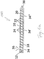
- Fig. 1a
- einen schematischen Längsschnitt einer erfindungsgemäßen Mischund Knetmaschine zeigt;
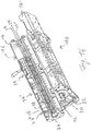
- Fig. 1b
- eine perspektivische Ansicht des Gehäuses der in der
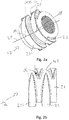
Fig. 1a gezeigten Misch- und Knetmaschine zeigt; - Fig. 2a
- eine perspektivische Ansicht eines axialen Abschnitts einer Schneckenwelle gemäß einer Ausführungsform der vorliegenden Erfindung zeigt;
- Fig. 2b
- eine Draufsicht des in der
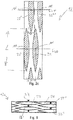
Fig. 2a gezeigten axialen Abschnitts der Schneckenwelle zeigt; - Fig. 2c
- die Abwicklung der Mantelfläche des Wellenstabes des in der
Fig. 2a gezeigten axialen Abschnitts der Schneckenwelle mit darauf angeordneten Flügelelementen zeigt; - Fig. 3
- die Abwicklung der Mantelfläche des Wellenstabes eines axialen Abschnitts einer Schneckenwelle mit darauf angeordneten Flügelelementen und in die Spalte zwischen den Flügelelementen hineinragenden Knetelementen gemäß einer anderen Ausführungsform der vorliegenden Erfindung zeigt;
- Fig. 4
- die Abwicklung der Mantelfläche des Wellenstabes eines axialen Abschnitts einer Schneckenwelle mit darauf angeordneten Flügelelementen und in die Spalte zwischen den Flügelelementen hineinragenden Knetelementen gemäß einer anderen Ausführungsform der vorliegenden Erfindung zeigt;
- Fig. 5
- die Abwicklung der Mantelfläche des Wellenstabes eines axialen Abschnitts einer Schneckenwelle mit darauf angeordneten Flügelelementen und in die Spalte zwischen den Flügelelementen hineinragenden Knetelementen gemäß einer anderen Ausführungsform der vorliegenden Erfindung zeigt und
- Fig. 6
- die Abwicklung der Mantelfläche des Wellenstabes eines axialen Abschnitts einer Schneckenwelle mit darauf angeordneten Flügelelementen und in die Spalte zwischen den Flügelelementen hineinragenden Knetelementen gemäß einer anderen Ausführungsform der vorliegenden Erfindung zeigt.
- Fig. 1a
- shows a schematic longitudinal section of a mixing and kneading machine according to the invention;
- Figure 1b
- a perspective view of the housing in FIG
Fig. 1a shows mixing and kneading machine shown; - Fig. 2a
- Figure 11 shows a perspective view of an axial portion of a worm shaft according to an embodiment of the present invention;
- Figure 2b
- a top view of the
Fig. 2a shows the axial section of the worm shaft shown; - Figure 2c
- the development of the outer surface of the wave bar in the
Fig. 2a shows the axial section of the worm shaft shown with wing elements arranged thereon; - Fig. 3
- shows the development of the lateral surface of the shaft rod of an axial section of a worm shaft with wing elements arranged thereon and kneading elements projecting into the gaps between the wing elements according to another embodiment of the present invention;
- Fig. 4
- shows the development of the lateral surface of the shaft rod of an axial section of a worm shaft with wing elements arranged thereon and kneading elements projecting into the gaps between the wing elements according to another embodiment of the present invention;
- Fig. 5
- shows the development of the lateral surface of the shaft rod of an axial section of a worm shaft with wing elements arranged thereon and kneading elements projecting into the gaps between the wing elements according to another embodiment of the present invention and
- Fig. 6
- shows the development of the lateral surface of the shaft rod of an axial section of a worm shaft with wing elements arranged thereon and kneading elements projecting into the gaps between the wing elements according to another embodiment of the present invention.
Die in den
Wie insbesondere aus der
Erfindungsgemäß ist die Schneckenwelle 12 für eine Misch- und Knetmaschine gemäß der vorliegenden Erfindung so ausgestaltet, dass die Flügelelemente 22 auf der Umfangsfläche des Wellenstabes 20, zumindest in einem sich in der axialen Richtung der Schneckenwelle 12 erstreckenden Abschnitt, wie dem in der
In den
Dabei sind sowohl die axial voneinander beabstandeten Flügelelemente 22, 22' in einer sich axial erstreckenden Reihe 40 als auch die axial voneinander beabstandeten Flügelelemente 22", 22'" in einer sich axial erstreckenden Reihe 40' angeordnet. Eine sich axial erstreckende Reihe 40, 40' von Flügelelementen 22, 22', 22", 22'" liegt gemäß der vorliegenden Erfindung vor, wenn - wie in der in den
Alle Längen L der Flügelelemente 22, 22', 22", 22'" erstrecken sich jeweils über den gleichen Winkelabschnitt von 195° über die (Außen)umfangsfläche bzw. Mantelfläche des Wellenstabes 20. Weil diese Winkel mehr als 180° betragen, überlappen sich die Enden der in Umfangsrichtung des Wellenstabes 20 benachbarten Flügelelemente 20, 20'" bzw. 20', 20" teilweise. Daher sind jeweils die im Querschnitt des Wellenstabes 20 gesehen in der Umfangsrichtung des Wellenstabes 20 benachbarten Flügelelemente 20, 20'" bzw. 20', 20" axial geringfügig zueinander versetzt, und zwar so, dass die beiden in der Umfangsrichtung des Wellenstabes 20 liegenden Enden der Flügelelemente axial um etwa 60% der Breite B eines Flügelelements 22, 22', 22", 22'" verschoben sind, so dass Bereiche dieser beiden Flügelelemente, wie das rechte Drittel des einen Flügelelements 22 und das linke Drittel des anderen Flügelelements 22'", in der Umfangsrichtung des Wellenstabes 20 des Wellenstabes gesehen, überlappen. Durch diese vergleichsweise lange Erstreckung der Flügelelemente 22, 22', 22", 22'" und die sich daraus ergebende teilweise Überlappung der Flügelelemente 22, 22', 22", 22'" wird nicht nur eine exzellente Förderleistung in Bezug auf die Menge der in Förderrichtung - pro Zeiteinheit und bezogen auf den Schneckenwellendurchmesser - geförderten Mischung erreicht, sondern insbesondere ein Rückfluss eines Teils der zu fördernden Mischung entgegen der Förderrichtung zuverlässig vermieden oder zumindest drastisch verringert. Dadurch wird in dem Innenraum 18 des Gehäuses 20, in dem die Schneckenwelle 12 angeordnet ist, eine geeignete Plastifizierung eingestellt, so dass auf Stauringe an der Innenumfangsfläche des Gehäuses 10, wie im Stand der Technik erforderlich, verzichtet werden kann, ohne dass sich unerwünschte Ablagerungen an der Schneckenwelle 12 ansammeln.All lengths L of the
In der
In den
- 1010
- Gehäusecasing
- 1212th
- SchneckenwelleWorm shaft
- 14, 14'14, 14 '
- GehäusehälfteHousing half
- 1616
- GehäuseschaleHousing shell
- 1818th
- Hohler InnenraumHollow interior
- 2020th
- WellenstabWave bar
- 22, 22', 22", 22'"22, 22 ', 22 ", 22'"
- FlügelelementWing element
- 2424
- Knetelement/KnetbolzenKneading element / kneading bolt
- 2828
- Aufnahme/Bohrung für KnetelementRecording / hole for kneading element
- 29, 29', 29"29, 29 ', 29 "
- (Axial erstreckende) Reihe von Aufnahme für Knetelemente(Axially extending) row of receptacles for kneading elements
- 34, 34', 34"34, 34 ', 34 "
- VerfahrensabschnittProcedural stage
- 3636
- FülltrichterHopper
- 3838
- AustrittsöffnungOutlet opening
- 40, 40'40, 40 '
- (Axial erstreckende) Reihe von Flügelelementen(Axially extending) row of wing elements
- 4242
- Seitliche Flanke eines FlügelelementsLateral flank of a wing element
- 100100
- Misch- und KnetmaschineMixing and kneading machine
- αα
- Winkel zwischen der Umfangsfläche des Wellenstabes und der seitlichen Flanke eines FlügelelementsAngle between the circumferential surface of the wave bar and the lateral flank of a wing element
- AA.
- Axialer Abstand A zweier benachbarter Flügelelemente einer ReiheAxial distance A between two adjacent wing elements in a row
- BB.
- Breite (längste gerade Erstreckung der Außenumfangsfläche des Flügelelements, welche sich senkrecht zu der Länge des Flügelelements erstreckt)Width (longest straight extension of the outer peripheral surface of the wing element, which extends perpendicular to the length of the wing element)
- LL.
- Länge (längste gerade Erstreckung der Außenumfangsfläche des Flügelelements)Length (longest straight extension of the outer peripheral surface of the wing element)
- MM.
- Mittelpunkt der Außenumfangsfläche eines FlügelelementsCenter of the outer peripheral surface of a wing element
Claims (14)
- Worm shaft (12) for a mixing and kneading machine (100), in particular for continuous treatment processes, comprising a shaft bar (20) having a circular cross section, with vane members (22, 22', 22", 22"') being arranged apart from each other on the circumferential surface thereof, said vane members (22, 22', 22", 22'") extend outward from the circumferential surface of the shaft bar (20), wherein the vane members (22, 22', 22", 22'") are arranged on the circumferential surface of the shaft bar (20), at least in a section extending in the axial direction of the worm shaft (12), in two rows (40, 40'), which extend in the axial direction of the worm shaft (12),
characterized in that
said section extending in the axial direction of the worm shaft (12) comprises no further vane members with the exception of the vane members arranged in two rows,
each of the vane members (22, 22', 22", 22'") of said section extending in the axial direction of the worm shaft (12) extends - as viewed from the cross section of the shaft bar (20) - over an angular distance of 20° to 160° or over an angular distance of at least 160°,
and that the section extending in the axial direction of the worm shaft (12), in which each of the vane members (22, 22', 22", 22'") extends over the aforementioned angular distance of the circumferential surface of the shaft bar (20), measures at least 0,2 D of the length of the worm shaft (12), with D being the diameter of the worm shaft. - Worm shaft (12) according to claim 1, characterized in that the vane members (22, 22', 22", 22"') extend radially outward from the circumferential surface of the shaft bar (20).
- Worm shaft (12) according to any one of claims 1 or 2, characterized in that the vane members (22, 22', 22", 22"') of the two rows (40, 40') face each other on the circumferential surface of the shaft bar (20) - as viewed from the cross section of the shaft bar (20).
- Worm shaft (12) according to at least any one of the preceding claims, characterized in that each of the vane members (22, 22', 22", 22'") of the at least one section extending in the axial direction of the worm shaft (12) comprises a longitudinal extension L, which extends at an angle to the axial direction of the worm shaft (12) of 45° to 135°, preferably of 60° to 120°, further preferred of 80° to 100°, highly preferred of 85° to 95° and mostly preferred of 90°.
- Worm shaft (12) according to at least any one of the preceding claims, characterized in that each of the vane members (22, 22', 22", 22'") of the at least one section extending in the axial direction of the worm shaft (12) comprises, in the plan view, an elliptical, oval or biconvex outer circumferential surface, wherein preferably the section extending in the axial direction of the worm shaft (12), with each vane member (22, 22', 22", 22'") thereof having the previously mentioned shape of its outer circumferential surface, preferably measures at least 0,5 D, further preferred at least 1 D and mostly preferred at least 10 D of the length of the worm shaft (12).
- Worm shaft (12) according to claim 5, characterized in that each of the vane members (22, 22', 22", 22"') comprises the same elliptical, oval or biconvex outer circumferential surface.
- Worm shaft (12) according to claim 5 or 6, characterized in that each of the vane members (22, 22', 22", 22'") comprises a biconvex outer circumferential surface with a ratio of length L to width W of 3 to 11, preferably 4 to 10, further preferred 5 to 9, highly preferred 6 to 8 and mostly preferred 7 to 7,5 with the length L being the longest straight extension of the outer circumferential surface of the vane member (22, 22', 22", 22"') and the width W being the longest straight extension of the outer circumferential surface of the vane member (22, 22', 22", 22"'), which extends perpendicularly to the length L of the vane member (22, 22', 22", 22'").
- Worm shaft (12) according to at least any one of claims 5 to 7, characterized in that the lateral flanks (42) of each of the vane members (22, 22', 22", 22"') extend from the circumferential direction of the shaft bar (20) either vertically upward to the outer circumferential surface (22, 22', 22", 22"') of the vane members (22, 22', 22", 22'") or in an angle α with respect to the cross-sectional plane of the shaft bar (20), which ranges from 1° to 60°, preferably from 2° to 40°, further preferred from 3° to 20° and mostly preferred from 4° to 10°.
- Worm shaft (12) according to at least any one of the preceding claims, characterized in that the ratio between the axial distance A of two adjacent vane members (22, 22', 22", 22'") of a row (40, 40') and the width W of a vane member (22, 22', 22", 22'") is 0,5 to 5, preferably 0,75 to 3, further preferred 1 to 2, highly preferred 1,25 to 1,75 and mostly preferred 1,4 to 1,6, with the width W being the longest straight extension of the outer circumferential surface of the vane member (22, 22', 22", 22'"), which extends perpendicularly to the length L of the vane member (22, 22', 22", 22"'), with the axial distance A of two adjacent vane members (22, 22', 22", 22'") being the distance between the centers C of the outer circumferential surfaces of the adjacent vane members (22, 22', 22", 22"'), with the center C of the outer circumferential surface of a vane member (22, 22', 22", 22"') being that point, which is located in the middle of the longest straight extension L of the outer circumferential surface of the vane member (22, 22', 22", 22'").
- Worm shaft (12) according to at least any one of the preceding claims, characterized in that each of the vane members (22, 22', 22", 22'") of the at least one section extending in the axial direction of the worm shaft (12) extends over an angular distance - as viewed from the cross section of the shaft bar (20) - of at least 170°, preferably of at least 175°, further preferred of more than 180°, yet further preferred of from more than 180° to 270°, particularly preferred from 185° to 230°, still further preferred from 185° to 210°, highly preferred from 190° to 200° and mostly preferred from 192° to 197° of the circumferential surface of the shaft bar (20), with preferentially the section extending in the axial direction of the worm shaft (12), in which each of the vane members (22, 22', 22", 22"') extend over the previously mentioned angular distance of the circumferential surface of the shaft bar (20), preferably measuring at least 0,5 D of the length of the worm shaft (12), further preferred at least 1 D and mostly preferred at least 10 D thereof.
- Worm shaft (12) according to at least any one of claims 5 to 9, characterized in that each of the vane members (22, 22', 22", 22"') of the at least one section extending in the axial direction of the worm shaft (12) extends over an angular distance - as viewed from the cross section of the shaft bar (20) - of from 45° to 135°, preferably from 60 to 120°, further preferred from 70° to 110°, highly preferred from 80° to 100° and mostly preferred from 85° to 95° of the circumferential surface of the shaft bar (20), with preferentially the section extending in the axial direction of the worm shaft (12), in which each of the vane members (22, 22', 22", 22"') extend over the previously mentioned angular distance of the circumferential surface of the shaft bar (20), measuring at least 0,5 D of the length of the worm shaft (12), further preferred at least 1 D and mostly preferred at least 10 D thereof.
- Worm shaft (12) according to at least any one of the preceding claims, characterized in that each of the vane members (22, 22', 22", 22'") of the at least one section extending in the axial direction of the worm shaft (12) extends - as viewed from the cross section of the shaft bar (20) - over the same angular distance of the circumferential surface of the shaft bar (20), with preferentially the section extending in the axial direction of the worm shaft (12), in which each of the vane members (22, 22', 22", 22'") extends over the same angular distance of the circumferential surface of the shaft bar (20), preferably measuring at least 0,5 D of the length of the worm shaft (12), further preferred at least 1 D and mostly preferred at least 10 D thereof.
- Housing (10) of a mixing and kneading machine (100) for continuous treatment processes, the housing (10) comprising a hollow inner space (18), in which a worm shaft (12) according at least to any one of claims 1 to 12 at least in sections extends in an axial direction, the housing (10) further comprising a multitude of kneading members (24), which extent from the inner circumferential surface of the housing (10) into the hollow inner space (18) of the housing (10), with the kneading members (24) being arranged in at least two rows, which extend in an axial direction over at least one section of the inner circumferential surface of the housing (10).
- Mixing and kneading machine (100) for continuous treatment processes, like for the preparation of granulated polymer, polymeric extruded profiles or polymeric moldings comprising a housing (10) according to claim 13.
Priority Applications (10)
| Application Number | Priority Date | Filing Date | Title |
|---|---|---|---|
| PL18170206T PL3473396T3 (en) | 2017-10-17 | 2018-04-30 | Asymmetric two-blade screw-type shaft for a mixing and kneading machine |
| JP2020521593A JP7358345B2 (en) | 2017-10-17 | 2018-10-02 | Double screw shaft for kneading machine |
| CN201880071478.XA CN111629874B (en) | 2017-10-17 | 2018-10-02 | Double-thread screw shaft for mixing kneader |
| US16/756,665 US11504680B2 (en) | 2017-10-17 | 2018-10-02 | Double-bladed worm shaft for a mixing and kneading machine, wherein each of the blade elements has an elliptic, oval, or bioconvex outer peripheral surface in the top view |
| CA3084408A CA3084408A1 (en) | 2017-10-17 | 2018-10-02 | Double-bladed worm shaft for a mixing and kneading machine |
| MX2020003874A MX2020003874A (en) | 2017-10-17 | 2018-10-02 | Twin-flight screw shaft for a mixing and kneading machine. |
| PCT/EP2018/076880 WO2019076631A1 (en) | 2017-10-17 | 2018-10-02 | Twin-flight screw shaft for a mixing and kneading machine |
| KR1020207013850A KR102637486B1 (en) | 2017-10-17 | 2018-10-02 | Mixing and kneading machine with double-blade worm shaft, sections and housing therefor. |
| TW107136563A TWI794306B (en) | 2017-10-17 | 2018-10-17 | Double-bladed worm shaft for a mixing and kneading machine, section for such a worm shaft, using containing the worm shaft, and corresponding mixing and kneading machine |
| US17/875,095 US20230077542A1 (en) | 2017-10-17 | 2022-07-27 | Double-bladed worm shaft for a mixing and kneading machine, wherein each of the blade elements has an elliptic, oval, or biconvex outer peripheral surface in the top view |
Applications Claiming Priority (2)
| Application Number | Priority Date | Filing Date | Title |
|---|---|---|---|
| EP17196908.2A EP3473404A1 (en) | 2017-10-17 | 2017-10-17 | Mixing and kneading device |
| EP18152448 | 2018-01-19 |
Publications (2)
| Publication Number | Publication Date |
|---|---|
| EP3473396A1 EP3473396A1 (en) | 2019-04-24 |
| EP3473396B1 true EP3473396B1 (en) | 2021-06-16 |
Family
ID=62017281
Family Applications (3)
| Application Number | Title | Priority Date | Filing Date |
|---|---|---|---|
| EP18170206.9A Active EP3473396B1 (en) | 2017-10-17 | 2018-04-30 | Asymmetric two-blade screw-type shaft for a mixing and kneading machine |
| EP18170198.8A Active EP3473395B1 (en) | 2017-10-17 | 2018-04-30 | Asymmetrical three-blade screw-type shaft for a mixing and kneading machine |
| EP18785315.5A Active EP3697587B1 (en) | 2017-10-17 | 2018-10-05 | Mixing and kneading machine with receiving areas for kneading elements, said receiving areas being distributed over the inner circumferential surface of the housing in a non-uniform manner |
Family Applications After (2)
| Application Number | Title | Priority Date | Filing Date |
|---|---|---|---|
| EP18170198.8A Active EP3473395B1 (en) | 2017-10-17 | 2018-04-30 | Asymmetrical three-blade screw-type shaft for a mixing and kneading machine |
| EP18785315.5A Active EP3697587B1 (en) | 2017-10-17 | 2018-10-05 | Mixing and kneading machine with receiving areas for kneading elements, said receiving areas being distributed over the inner circumferential surface of the housing in a non-uniform manner |
Country Status (12)
| Country | Link |
|---|---|
| US (5) | US11779891B2 (en) |
| EP (3) | EP3473396B1 (en) |
| JP (4) | JP7358345B2 (en) |
| KR (3) | KR102637485B1 (en) |
| CN (3) | CN111655440B (en) |
| CA (3) | CA3084408A1 (en) |
| ES (3) | ES2880393T3 (en) |
| MX (3) | MX2020003876A (en) |
| PL (3) | PL3473396T3 (en) |
| SI (1) | SI3697587T1 (en) |
| TW (3) | TWI794306B (en) |
| WO (3) | WO2019076631A1 (en) |
Cited By (1)
| Publication number | Priority date | Publication date | Assignee | Title |
|---|---|---|---|---|
| RU212584U1 (en) * | 2022-04-21 | 2022-07-29 | Федеральное государственное автономное образовательное учреждение высшего образования "Крымский федеральный университет имени В.И. Вернадского" | Extruder for processing dissimilar secondary polymeric and building materials |
Families Citing this family (5)
| Publication number | Priority date | Publication date | Assignee | Title |
|---|---|---|---|---|
| PL3473396T3 (en) * | 2017-10-17 | 2021-12-13 | Buss Ag | Asymmetric two-blade screw-type shaft for a mixing and kneading machine |
| USD929799S1 (en) | 2018-05-04 | 2021-09-07 | Buss Ag | Screw shaft element |
| US11472089B2 (en) * | 2018-05-04 | 2022-10-18 | Case Western Reserve University | Mixing element having projections defining channels of varying width and depth for extrusion operations |
| USD938500S1 (en) | 2018-05-18 | 2021-12-14 | Buss Ag | Mixing and kneading machine |
| EP3750622B1 (en) * | 2019-06-11 | 2022-01-12 | Buss AG | Mixing and kneading machine housing for symmetric 2-, 3- and 4-leaf screw elements |
Family Cites Families (79)
| Publication number | Priority date | Publication date | Assignee | Title |
|---|---|---|---|---|
| CH278575A (en) | 1949-11-04 | 1951-10-31 | List Heinz | Mixing and kneading machine. |
| BE502256A (en) * | 1950-08-09 | 1951-04-14 | Pirelli | CONTINUOUS MACHINE FOR MIXING, PLASTICIZING OR PREHEATING RUBBER OR OTHER PLASTICS |
| BE607376A (en) * | 1960-08-22 | 1900-01-01 | ||
| CH407525A (en) * | 1964-01-23 | 1966-02-15 | Buss Ag | Kneading and mixing device |
| US3458894A (en) * | 1966-09-13 | 1969-08-05 | Baker Perkins Inc | Mixing apparatus |
| US3486192A (en) * | 1967-03-24 | 1969-12-30 | Union Carbide Corp | Apparatus for extrusion of thermoplastics |
| US3486194A (en) * | 1967-08-07 | 1969-12-30 | Clarence E Parks | Extruder |
| CH507733A (en) | 1969-04-02 | 1971-05-31 | Buss Ag | Mixing and kneading device |
| US3938783A (en) * | 1970-10-30 | 1976-02-17 | The Upjohn Company | Method for continuous mixing of foam materials |
| US3751015A (en) * | 1971-06-22 | 1973-08-07 | Barmag Barmer Maschf | Screw extruder with radially projecting pins |
| US3804382A (en) * | 1971-07-01 | 1974-04-16 | Cincinnati Milacron Inc | Extruder construction |
| US3981658A (en) * | 1972-01-14 | 1976-09-21 | International Basic Economy Corporation | Screw type apparatus for drying moist polymeric materials |
| US3841611A (en) * | 1972-07-14 | 1974-10-15 | Buss Ag | Mixing and kneading device |
| US4199263A (en) * | 1972-07-21 | 1980-04-22 | Uniroyal Ag | Method and apparatus for mixing viscous materials |
| DE2235784C3 (en) | 1972-07-21 | 1986-01-09 | Uniroyal Englebert Reifen GmbH, 5100 Aachen | Single-screw extruder for mixing and homogenizing high-viscosity rubber compounds and high-viscosity thermoplastics |
| JPS5641301B2 (en) * | 1972-08-10 | 1981-09-28 | ||
| DE2307616B2 (en) * | 1973-02-16 | 1975-06-05 | Hermann Berstorff Maschinenbau Gmbh, 3000 Hannover | Single or multi-start extruder screw for processing thermoplastics or rubber-like materials |
| US3902850A (en) * | 1974-03-18 | 1975-09-02 | Upjohn Co | Solvent-free, self-cleaning mixing head nozzles for reactive polymer mixes |
| JPS5530988Y2 (en) * | 1974-06-12 | 1980-07-24 | ||
| JPS5179048A (en) * | 1974-12-27 | 1976-07-09 | Exxon Research Engineering Co | |
| CH614401A5 (en) | 1975-10-24 | 1979-11-30 | Toyo Soda Mfg Co Ltd | |
| CA1074780A (en) * | 1976-07-14 | 1980-04-01 | Frenkel C-D Aktiengesellschaft | Opposite handed variable groove threaded screw and barrel transfer mixer |
| US4304054A (en) * | 1980-04-21 | 1981-12-08 | The B. F. Goodrich Company | Screw press for drying elastomeric polymers |
| US4361081A (en) * | 1980-08-11 | 1982-11-30 | Howard James R | Apparatus for processing oilseed and grain mash products |
| DE3043194A1 (en) * | 1980-11-15 | 1982-07-01 | Hermann Berstorff Maschinenbau Gmbh, 3000 Hannover | DEVICE FOR MECHANICALLY SEPARATING LIQUIDS FROM LIQUIDS-SOLIDS MIXTURES IN A SCREW PRESS |
| DE3132429A1 (en) * | 1981-08-17 | 1983-02-24 | Krauss-Maffei AG, 8000 München | Screw for processing plastics, in particular for an injection-moulding machine |
| DE3150719A1 (en) * | 1981-12-22 | 1983-06-30 | Uniroyal Englebert Reifen GmbH, 5100 Aachen | SNAIL EXTRUDERS |
| DE3225512A1 (en) * | 1982-07-08 | 1984-01-12 | Continental Gummi-Werke Ag, 3000 Hannover | EXTRUSION PRESS |
| DE3275070D1 (en) * | 1982-08-26 | 1987-02-19 | Berstorff Gmbh Masch Hermann | EXTRUDER WITH VENT ZONE |
| DE3475283D1 (en) * | 1983-10-17 | 1988-12-29 | Renato Fornasero | Process for recovery of heterogeneous waste plastic materials, and apparatus usable in carrying out the same |
| DE3430254A1 (en) * | 1984-08-17 | 1986-02-27 | Hoechst Ag, 6230 Frankfurt | SNAIL EXTRUDERS |
| US4629327A (en) * | 1985-01-29 | 1986-12-16 | Hermann Berstorff Maschinenbau Gmbh | Pin-barrel extruder having adjustable pins |
| DE3506424C1 (en) * | 1985-02-23 | 1986-08-21 | Hermann Berstorff Maschinenbau Gmbh, 3000 Hannover | Pen adjustment device on a pen extruder for the processing of rubber or thermoplastic materials |
| ES8607810A1 (en) * | 1985-04-30 | 1986-06-01 | Gumix Sa | Turbomixer-extruder machine |
| GB2178691B (en) * | 1985-07-16 | 1989-10-25 | Farrel Bridge Ltd | Screw extruders |
| DE3541499C1 (en) * | 1985-11-23 | 1993-06-03 | Hermann Berstorff Maschinenbau Gmbh, 3000 Hannover | Pin cylinder extruder with a cylinder tempering device |
| JPS62134714U (en) * | 1986-02-19 | 1987-08-25 | ||
| US5044759A (en) * | 1987-05-20 | 1991-09-03 | Giuseppe Gagliani | Mixing process and screw extruders for carrying out the same |
| DE3772991D1 (en) * | 1987-08-21 | 1991-10-17 | Schumacher Walter | DEVICE FOR EXTRUDING, EXPANDING AND / OR THERMALLY TREATING SUBSTANCES AND SUBSTANCE MIXTURES. |
| DE4010540C1 (en) * | 1990-04-02 | 1991-11-07 | Wilfried Dipl.-Ing. 3017 Pattensen De Baumgarten | |
| DE4039942C1 (en) * | 1990-12-14 | 1992-01-30 | Berstorff Gmbh Masch Hermann | |
| GB2255039A (en) * | 1991-04-19 | 1992-10-28 | Frenkel Ag C D | Cold feed rubber extruder construction. |
| US5304054A (en) * | 1991-04-19 | 1994-04-19 | Frenkel C-D Aktiengesellschaft | Plasticizing sections of cold feed rubber extruders |
| DE4118091A1 (en) * | 1991-06-03 | 1992-12-10 | Theysohn Friedrich Fa | DEVICE FOR PLASTICIZING PLASTIC |
| IT1250016B (en) * | 1991-09-11 | 1995-03-30 | Renato Fornasero | IMPROVEMENT IN THE DEVICES FOR THE RECOVERY OF HETEROGENEOUS WASTE, PARTICULARLY HETEROGENEOUS WASTE OF PLASTIC MATERIALS. |
| DE4141328C1 (en) | 1991-12-14 | 1993-02-04 | Buss Ag, Basel, Ch | |
| JPH07276462A (en) | 1994-04-07 | 1995-10-24 | Mitsuba Seisakusho:Kk | Extruder for coating water foaming resin |
| US5932159A (en) | 1997-11-07 | 1999-08-03 | Rauwendaal Extrusion Engineering, Inc. | Screw extruder with improved dispersive mixing |
| US6132077A (en) | 1998-05-26 | 2000-10-17 | Fogarty; James D. | Method of cooling a foam extrusion mixture to an extrudable temperature |
| US6152592A (en) * | 1999-02-18 | 2000-11-28 | Klein; Ron J. | Mixing devices having an array of spaced apart mixing elements for intercepting a flowing stream of material and contoured to mix constituents in the stream |
| US6250791B1 (en) * | 2000-06-16 | 2001-06-26 | Loren T. Schneider | Liner and pin assembly for use with an apparatus for kneading or mixing materials |
| US6547431B1 (en) * | 2000-11-09 | 2003-04-15 | Milacron Inc. | Mixing section for a feed screw and methods of making the same |
| DE60044147D1 (en) * | 2000-11-13 | 2010-05-20 | Morinaga & Co | kneading |
| US6709147B1 (en) | 2002-12-05 | 2004-03-23 | Rauwendaal Extrusion Engineering, Inc. | Intermeshing element mixer |
| CH695934A5 (en) | 2003-03-27 | 2006-10-31 | Coperion Buss Ag | Mixing and kneading machine comprises a throttling system consisting of baffles that extend into a working chamber and can be displaced radially and/or rotated about their longitudinal axis |
| CN2626600Y (en) * | 2003-08-05 | 2004-07-21 | 周凤举 | Non-helical reciprocating rotation stirring machine |
| US7246936B2 (en) * | 2004-06-04 | 2007-07-24 | Certainteed Corp. | Dynamic mixer screw tip |
| US7390118B2 (en) * | 2004-10-15 | 2008-06-24 | Husky Injection Molding Systems Ltd. | Extruder assembly |
| JP4338668B2 (en) * | 2005-04-05 | 2009-10-07 | 住友ゴム工業株式会社 | Rubber extruder |
| DE502007000130D1 (en) | 2006-02-06 | 2008-11-13 | Buss Ag | Mixing and kneading machine |
| DE102006010458A1 (en) * | 2006-03-03 | 2007-09-06 | Reimelt Henschel Mischsysteme Gmbh | Mixing and kneading machine for plastic materials |
| AT504854B1 (en) * | 2007-02-15 | 2012-08-15 | Erema | METHOD AND DEVICE FOR PREPARING A MATERIAL |
| PL2018946T3 (en) * | 2007-07-25 | 2017-07-31 | Buss Ag | Mixing and kneading machine for continuous preparation processes and method for carrying out continuous preparation processes with a mixing and kneading machine |
| CH700976A1 (en) | 2009-05-11 | 2010-11-15 | Buss Ag | Mixing and kneading machine for continuous treatment processes as well as procedures for carrying out continuous preparation processes by means of a mixing and kneading machine. |
| CH701030B1 (en) | 2009-05-11 | 2013-05-31 | Buss Ag | Mixing and kneading machine for continuous treatment processes as well as procedures for carrying out continuous preparation processes by means of a mixing and kneading machine. |
| JP5804281B2 (en) * | 2009-07-16 | 2015-11-04 | ブラフ,ヨセフ,エー. | Extruder |
| FR2975330B1 (en) * | 2011-05-19 | 2013-06-28 | Michelin Soc Tech | METHOD OF ASSESSING THE PERFORMANCE OF A HOMOGENEIZER PLACED IN AN EXTRUSION LINE |
| CN202318878U (en) | 2011-11-10 | 2012-07-11 | 上海金昌工程塑料有限公司 | Screw rod assembly of double-screw extruder |
| JP2014091320A (en) * | 2012-11-07 | 2014-05-19 | Sekisui Chem Co Ltd | Screw for extrusion molding machine |
| US9862121B2 (en) * | 2012-12-17 | 2018-01-09 | B&P Littleford Llc | Kneading method and apparatus |
| CN103057088B (en) | 2012-12-20 | 2016-01-20 | 华南理工大学 | Based on tensile deformation effect intensifying method and the screw rod of reverse eccentric two thread groove |
| CN103192514A (en) * | 2013-03-29 | 2013-07-10 | 江苏德威新材料股份有限公司 | Preparation method of high-voltage semi-conduction electric screening material |
| JP6396953B2 (en) * | 2016-07-13 | 2018-09-26 | 株式会社日本製鋼所 | Kneading disc, screw element and extruder |
| CN206426435U (en) | 2016-12-08 | 2017-08-22 | 北京工商大学 | A kind of shearing mixing area can be with the double screw extruder of real-time temperature control |
| EP3473404A1 (en) * | 2017-10-17 | 2019-04-24 | Buss AG | Mixing and kneading device |
| PL3473396T3 (en) * | 2017-10-17 | 2021-12-13 | Buss Ag | Asymmetric two-blade screw-type shaft for a mixing and kneading machine |
| ES2862979T3 (en) * | 2018-05-02 | 2021-10-08 | Buss Ag | Mixing and kneading machine and its use |
| USD929799S1 (en) * | 2018-05-04 | 2021-09-07 | Buss Ag | Screw shaft element |
| USD961990S1 (en) * | 2018-05-04 | 2022-08-30 | Buss Ag | Screw shaft element |
-
2018
- 2018-04-30 PL PL18170206T patent/PL3473396T3/en unknown
- 2018-04-30 EP EP18170206.9A patent/EP3473396B1/en active Active
- 2018-04-30 ES ES18170206T patent/ES2880393T3/en active Active
- 2018-04-30 PL PL18170198T patent/PL3473395T3/en unknown
- 2018-04-30 EP EP18170198.8A patent/EP3473395B1/en active Active
- 2018-04-30 ES ES18170198T patent/ES2868896T3/en active Active
- 2018-10-02 MX MX2020003876A patent/MX2020003876A/en unknown
- 2018-10-02 MX MX2020003874A patent/MX2020003874A/en unknown
- 2018-10-02 JP JP2020521593A patent/JP7358345B2/en active Active
- 2018-10-02 WO PCT/EP2018/076880 patent/WO2019076631A1/en active Application Filing
- 2018-10-02 CN CN201880071753.8A patent/CN111655440B/en active Active
- 2018-10-02 KR KR1020207013853A patent/KR102637485B1/en active IP Right Grant
- 2018-10-02 US US16/756,726 patent/US11779891B2/en active Active
- 2018-10-02 JP JP2020521604A patent/JP7390286B2/en active Active
- 2018-10-02 WO PCT/EP2018/076883 patent/WO2019076632A1/en active Application Filing
- 2018-10-02 CA CA3084408A patent/CA3084408A1/en active Pending
- 2018-10-02 US US16/756,665 patent/US11504680B2/en active Active
- 2018-10-02 KR KR1020207013850A patent/KR102637486B1/en active IP Right Grant
- 2018-10-02 CN CN201880071478.XA patent/CN111629874B/en active Active
- 2018-10-02 CA CA3079485A patent/CA3079485A1/en active Pending
- 2018-10-05 ES ES18785315T patent/ES2910192T3/en active Active
- 2018-10-05 EP EP18785315.5A patent/EP3697587B1/en active Active
- 2018-10-05 JP JP2020521603A patent/JP7358346B2/en active Active
- 2018-10-05 SI SI201830658T patent/SI3697587T1/en unknown
- 2018-10-05 CA CA3079448A patent/CA3079448A1/en active Pending
- 2018-10-05 MX MX2020003881A patent/MX2020003881A/en unknown
- 2018-10-05 US US16/756,688 patent/US11331634B2/en active Active
- 2018-10-05 CN CN201880070572.3A patent/CN111629873B/en active Active
- 2018-10-05 WO PCT/EP2018/077199 patent/WO2019076656A1/en unknown
- 2018-10-05 PL PL18785315T patent/PL3697587T3/en unknown
- 2018-10-05 KR KR1020207013871A patent/KR102643550B1/en active IP Right Grant
- 2018-10-17 TW TW107136563A patent/TWI794306B/en active
- 2018-10-17 TW TW107136564A patent/TWI791643B/en active
- 2018-10-17 TW TW107136561A patent/TWI794305B/en active
-
2022
- 2022-07-27 US US17/875,095 patent/US20230077542A1/en active Pending
- 2022-12-02 JP JP2022193180A patent/JP2023027158A/en active Pending
-
2023
- 2023-04-14 US US18/134,807 patent/US20230249143A1/en active Pending
Non-Patent Citations (1)
| Title |
|---|
| None * |
Cited By (2)
| Publication number | Priority date | Publication date | Assignee | Title |
|---|---|---|---|---|
| RU212584U1 (en) * | 2022-04-21 | 2022-07-29 | Федеральное государственное автономное образовательное учреждение высшего образования "Крымский федеральный университет имени В.И. Вернадского" | Extruder for processing dissimilar secondary polymeric and building materials |
| RU212698U1 (en) * | 2022-04-21 | 2022-08-03 | Федеральное государственное автономное образовательное учреждение высшего образования "Крымский федеральный университет имени В.И. Вернадского" | Extruder for processing dissimilar secondary polymeric and building materials |
Also Published As
Similar Documents
| Publication | Publication Date | Title |
|---|---|---|
| EP3473396B1 (en) | Asymmetric two-blade screw-type shaft for a mixing and kneading machine | |
| DE4134026C2 (en) | Co-rotating screw kneader | |
| DE2624048C2 (en) | Continuous mixer | |
| EP0694378B1 (en) | Twin screw extruder | |
| EP1523403B1 (en) | Extruder | |
| DE2307717B2 (en) | CONTINUOUSLY WORKING MIXING DEVICE FOR PLASTIC MASSES | |
| DE1502335B2 (en) | SCREW EXTRUSION PRESS FOR THE PROCESSING OF PLASTIC | |
| EP2272651B1 (en) | Screw machine with dispersive mixing element | |
| DE2516376C3 (en) | Single screw extruder for high molecular weight substances | |
| EP0090257B1 (en) | Mixing apparatus for producing a chemically reactive mixture of at least two liquid plastics components | |
| EP2212090B1 (en) | Screw for a screw extruder | |
| EP1775099A2 (en) | Extruder screw with mixing pins | |
| EP1649995A2 (en) | Internal mixer for kneading plastic materials | |
| EP3564005B1 (en) | Mixing and kneading device, and its use | |
| DE2514307A1 (en) | SCREW HOUSING FOR AN EXTRUDER OR INJECTION MOLDING MACHINE | |
| DE2513577B2 (en) | Continuously working mixer for plastic materials | |
| CH646371A5 (en) | Screw extruder for the continuous compounding of plasticatable compositions | |
| EP3656523B1 (en) | Mixing and kneading machine with efficient venting in the area of the feed-in, and related method | |
| DE102015014865A1 (en) | Multi-shaft continuous mixing and kneading machine for plasticizable masses | |
| EP0641640A1 (en) | Screw element for screw machine | |
| EP0479718B1 (en) | Mixing and kneading device | |
| DE963688C (en) | Device for handling viscous, doughy, gritty or fibrous masses | |
| EP3750622B1 (en) | Mixing and kneading machine housing for symmetric 2-, 3- and 4-leaf screw elements | |
| DE3009233C2 (en) | Mixing device | |
| DE102022123406A1 (en) | TWIN SCREW EXTRUDER AND METHOD FOR PROCESSING A RUBBER MATERIAL |
Legal Events
| Date | Code | Title | Description |
|---|---|---|---|
| PUAI | Public reference made under article 153(3) epc to a published international application that has entered the european phase |
Free format text: ORIGINAL CODE: 0009012 |
|
| STAA | Information on the status of an ep patent application or granted ep patent |
Free format text: STATUS: THE APPLICATION HAS BEEN PUBLISHED |
|
| AK | Designated contracting states |
Kind code of ref document: A1 Designated state(s): AL AT BE BG CH CY CZ DE DK EE ES FI FR GB GR HR HU IE IS IT LI LT LU LV MC MK MT NL NO PL PT RO RS SE SI SK SM TR |
|
| AX | Request for extension of the european patent |
Extension state: BA ME |
|
| STAA | Information on the status of an ep patent application or granted ep patent |
Free format text: STATUS: REQUEST FOR EXAMINATION WAS MADE |
|
| 17P | Request for examination filed |
Effective date: 20191021 |
|
| RBV | Designated contracting states (corrected) |
Designated state(s): AL AT BE BG CH CY CZ DE DK EE ES FI FR GB GR HR HU IE IS IT LI LT LU LV MC MK MT NL NO PL PT RO RS SE SI SK SM TR |
|
| STAA | Information on the status of an ep patent application or granted ep patent |
Free format text: STATUS: EXAMINATION IS IN PROGRESS |
|
| 17Q | First examination report despatched |
Effective date: 20200226 |
|
| STAA | Information on the status of an ep patent application or granted ep patent |
Free format text: STATUS: EXAMINATION IS IN PROGRESS |
|
| GRAP | Despatch of communication of intention to grant a patent |
Free format text: ORIGINAL CODE: EPIDOSNIGR1 |
|
| STAA | Information on the status of an ep patent application or granted ep patent |
Free format text: STATUS: GRANT OF PATENT IS INTENDED |
|
| RIC1 | Information provided on ipc code assigned before grant |
Ipc: B29C 48/45 20190101ALI20210204BHEP Ipc: B29C 48/685 20190101ALI20210204BHEP Ipc: B29B 7/42 20060101AFI20210204BHEP Ipc: B29C 48/565 20190101ALI20210204BHEP |
|
| INTG | Intention to grant announced |
Effective date: 20210303 |
|
| GRAS | Grant fee paid |
Free format text: ORIGINAL CODE: EPIDOSNIGR3 |
|
| GRAA | (expected) grant |
Free format text: ORIGINAL CODE: 0009210 |
|
| STAA | Information on the status of an ep patent application or granted ep patent |
Free format text: STATUS: THE PATENT HAS BEEN GRANTED |
|
| AK | Designated contracting states |
Kind code of ref document: B1 Designated state(s): AL AT BE BG CH CY CZ DE DK EE ES FI FR GB GR HR HU IE IS IT LI LT LU LV MC MK MT NL NO PL PT RO RS SE SI SK SM TR |
|
| REG | Reference to a national code |
Ref country code: GB Ref legal event code: FG4D Free format text: NOT ENGLISH |
|
| REG | Reference to a national code |
Ref country code: CH Ref legal event code: EP |
|
| REG | Reference to a national code |
Ref country code: DE Ref legal event code: R096 Ref document number: 502018005706 Country of ref document: DE |
|
| REG | Reference to a national code |
Ref country code: AT Ref legal event code: REF Ref document number: 1401943 Country of ref document: AT Kind code of ref document: T Effective date: 20210715 |
|
| REG | Reference to a national code |
Ref country code: IE Ref legal event code: FG4D Free format text: LANGUAGE OF EP DOCUMENT: GERMAN |
|
| REG | Reference to a national code |
Ref country code: NL Ref legal event code: FP |
|
| REG | Reference to a national code |
Ref country code: LT Ref legal event code: MG9D |
|
| PG25 | Lapsed in a contracting state [announced via postgrant information from national office to epo] |
Ref country code: HR Free format text: LAPSE BECAUSE OF FAILURE TO SUBMIT A TRANSLATION OF THE DESCRIPTION OR TO PAY THE FEE WITHIN THE PRESCRIBED TIME-LIMIT Effective date: 20210616 Ref country code: LT Free format text: LAPSE BECAUSE OF FAILURE TO SUBMIT A TRANSLATION OF THE DESCRIPTION OR TO PAY THE FEE WITHIN THE PRESCRIBED TIME-LIMIT Effective date: 20210616 Ref country code: FI Free format text: LAPSE BECAUSE OF FAILURE TO SUBMIT A TRANSLATION OF THE DESCRIPTION OR TO PAY THE FEE WITHIN THE PRESCRIBED TIME-LIMIT Effective date: 20210616 Ref country code: BG Free format text: LAPSE BECAUSE OF FAILURE TO SUBMIT A TRANSLATION OF THE DESCRIPTION OR TO PAY THE FEE WITHIN THE PRESCRIBED TIME-LIMIT Effective date: 20210916 |
|
| REG | Reference to a national code |
Ref country code: ES Ref legal event code: FG2A Ref document number: 2880393 Country of ref document: ES Kind code of ref document: T3 Effective date: 20211124 |
|
| PG25 | Lapsed in a contracting state [announced via postgrant information from national office to epo] |
Ref country code: GR Free format text: LAPSE BECAUSE OF FAILURE TO SUBMIT A TRANSLATION OF THE DESCRIPTION OR TO PAY THE FEE WITHIN THE PRESCRIBED TIME-LIMIT Effective date: 20210917 Ref country code: RS Free format text: LAPSE BECAUSE OF FAILURE TO SUBMIT A TRANSLATION OF THE DESCRIPTION OR TO PAY THE FEE WITHIN THE PRESCRIBED TIME-LIMIT Effective date: 20210616 Ref country code: SE Free format text: LAPSE BECAUSE OF FAILURE TO SUBMIT A TRANSLATION OF THE DESCRIPTION OR TO PAY THE FEE WITHIN THE PRESCRIBED TIME-LIMIT Effective date: 20210616 Ref country code: LV Free format text: LAPSE BECAUSE OF FAILURE TO SUBMIT A TRANSLATION OF THE DESCRIPTION OR TO PAY THE FEE WITHIN THE PRESCRIBED TIME-LIMIT Effective date: 20210616 Ref country code: NO Free format text: LAPSE BECAUSE OF FAILURE TO SUBMIT A TRANSLATION OF THE DESCRIPTION OR TO PAY THE FEE WITHIN THE PRESCRIBED TIME-LIMIT Effective date: 20210916 |
|
| PG25 | Lapsed in a contracting state [announced via postgrant information from national office to epo] |
Ref country code: SM Free format text: LAPSE BECAUSE OF FAILURE TO SUBMIT A TRANSLATION OF THE DESCRIPTION OR TO PAY THE FEE WITHIN THE PRESCRIBED TIME-LIMIT Effective date: 20210616 Ref country code: SK Free format text: LAPSE BECAUSE OF FAILURE TO SUBMIT A TRANSLATION OF THE DESCRIPTION OR TO PAY THE FEE WITHIN THE PRESCRIBED TIME-LIMIT Effective date: 20210616 Ref country code: EE Free format text: LAPSE BECAUSE OF FAILURE TO SUBMIT A TRANSLATION OF THE DESCRIPTION OR TO PAY THE FEE WITHIN THE PRESCRIBED TIME-LIMIT Effective date: 20210616 Ref country code: PT Free format text: LAPSE BECAUSE OF FAILURE TO SUBMIT A TRANSLATION OF THE DESCRIPTION OR TO PAY THE FEE WITHIN THE PRESCRIBED TIME-LIMIT Effective date: 20211018 Ref country code: RO Free format text: LAPSE BECAUSE OF FAILURE TO SUBMIT A TRANSLATION OF THE DESCRIPTION OR TO PAY THE FEE WITHIN THE PRESCRIBED TIME-LIMIT Effective date: 20210616 |
|
| REG | Reference to a national code |
Ref country code: DE Ref legal event code: R097 Ref document number: 502018005706 Country of ref document: DE |
|
| PLBE | No opposition filed within time limit |
Free format text: ORIGINAL CODE: 0009261 |
|
| STAA | Information on the status of an ep patent application or granted ep patent |
Free format text: STATUS: NO OPPOSITION FILED WITHIN TIME LIMIT |
|
| PG25 | Lapsed in a contracting state [announced via postgrant information from national office to epo] |
Ref country code: DK Free format text: LAPSE BECAUSE OF FAILURE TO SUBMIT A TRANSLATION OF THE DESCRIPTION OR TO PAY THE FEE WITHIN THE PRESCRIBED TIME-LIMIT Effective date: 20210616 |
|
| 26N | No opposition filed |
Effective date: 20220317 |
|
| PG25 | Lapsed in a contracting state [announced via postgrant information from national office to epo] |
Ref country code: AL Free format text: LAPSE BECAUSE OF FAILURE TO SUBMIT A TRANSLATION OF THE DESCRIPTION OR TO PAY THE FEE WITHIN THE PRESCRIBED TIME-LIMIT Effective date: 20210616 |
|
| PG25 | Lapsed in a contracting state [announced via postgrant information from national office to epo] |
Ref country code: MC Free format text: LAPSE BECAUSE OF FAILURE TO SUBMIT A TRANSLATION OF THE DESCRIPTION OR TO PAY THE FEE WITHIN THE PRESCRIBED TIME-LIMIT Effective date: 20210616 Ref country code: LU Free format text: LAPSE BECAUSE OF NON-PAYMENT OF DUE FEES Effective date: 20220430 |
|
| PG25 | Lapsed in a contracting state [announced via postgrant information from national office to epo] |
Ref country code: IE Free format text: LAPSE BECAUSE OF NON-PAYMENT OF DUE FEES Effective date: 20220430 |
|
| PGFP | Annual fee paid to national office [announced via postgrant information from national office to epo] |
Ref country code: NL Payment date: 20230419 Year of fee payment: 6 |
|
| P01 | Opt-out of the competence of the unified patent court (upc) registered |
Effective date: 20230608 |
|
| PGFP | Annual fee paid to national office [announced via postgrant information from national office to epo] |
Ref country code: FR Payment date: 20230424 Year of fee payment: 6 Ref country code: ES Payment date: 20230627 Year of fee payment: 6 Ref country code: DE Payment date: 20230420 Year of fee payment: 6 Ref country code: CZ Payment date: 20230425 Year of fee payment: 6 Ref country code: CH Payment date: 20230502 Year of fee payment: 6 Ref country code: IT Payment date: 20230426 Year of fee payment: 6 |
|
| PGFP | Annual fee paid to national office [announced via postgrant information from national office to epo] |
Ref country code: TR Payment date: 20230428 Year of fee payment: 6 Ref country code: PL Payment date: 20230424 Year of fee payment: 6 |
|
| PGFP | Annual fee paid to national office [announced via postgrant information from national office to epo] |
Ref country code: BE Payment date: 20230419 Year of fee payment: 6 |
|
| PGFP | Annual fee paid to national office [announced via postgrant information from national office to epo] |
Ref country code: GB Payment date: 20230419 Year of fee payment: 6 |
|
| PG25 | Lapsed in a contracting state [announced via postgrant information from national office to epo] |
Ref country code: HU Free format text: LAPSE BECAUSE OF FAILURE TO SUBMIT A TRANSLATION OF THE DESCRIPTION OR TO PAY THE FEE WITHIN THE PRESCRIBED TIME-LIMIT; INVALID AB INITIO Effective date: 20180430 |
|
| PG25 | Lapsed in a contracting state [announced via postgrant information from national office to epo] |
Ref country code: MK Free format text: LAPSE BECAUSE OF FAILURE TO SUBMIT A TRANSLATION OF THE DESCRIPTION OR TO PAY THE FEE WITHIN THE PRESCRIBED TIME-LIMIT Effective date: 20210616 Ref country code: CY Free format text: LAPSE BECAUSE OF FAILURE TO SUBMIT A TRANSLATION OF THE DESCRIPTION OR TO PAY THE FEE WITHIN THE PRESCRIBED TIME-LIMIT Effective date: 20210616 |