EP3564005B1 - Mixing and kneading device, and its use - Google Patents
Mixing and kneading device, and its use Download PDFInfo
- Publication number
- EP3564005B1 EP3564005B1 EP18170447.9A EP18170447A EP3564005B1 EP 3564005 B1 EP3564005 B1 EP 3564005B1 EP 18170447 A EP18170447 A EP 18170447A EP 3564005 B1 EP3564005 B1 EP 3564005B1
- Authority
- EP
- European Patent Office
- Prior art keywords
- mixing
- connecting element
- housing
- kneading
- kneading machine
- Prior art date
- Legal status (The legal status is an assumption and is not a legal conclusion. Google has not performed a legal analysis and makes no representation as to the accuracy of the status listed.)
- Active
Links
- 238000002156 mixing Methods 0.000 title claims description 150
- 238000004898 kneading Methods 0.000 title claims description 147
- 238000007872 degassing Methods 0.000 claims description 67
- 229920000642 polymer Polymers 0.000 claims description 31
- XLYOFNOQVPJJNP-UHFFFAOYSA-N water Substances O XLYOFNOQVPJJNP-UHFFFAOYSA-N 0.000 claims description 27
- 238000005469 granulation Methods 0.000 claims description 26
- 230000003179 granulation Effects 0.000 claims description 26
- 239000008187 granular material Substances 0.000 claims description 19
- 238000004519 manufacturing process Methods 0.000 claims description 9
- 230000004323 axial length Effects 0.000 claims description 8
- 238000002360 preparation method Methods 0.000 claims description 6
- 238000005520 cutting process Methods 0.000 claims description 4
- 239000000203 mixture Substances 0.000 description 60
- 239000000155 melt Substances 0.000 description 23
- 238000000034 method Methods 0.000 description 13
- 230000008569 process Effects 0.000 description 13
- 230000002093 peripheral effect Effects 0.000 description 10
- 239000000463 material Substances 0.000 description 9
- 238000004140 cleaning Methods 0.000 description 7
- 239000007858 starting material Substances 0.000 description 7
- 239000007789 gas Substances 0.000 description 6
- 230000007704 transition Effects 0.000 description 6
- 238000011144 upstream manufacturing Methods 0.000 description 6
- 239000000470 constituent Substances 0.000 description 5
- 230000010006 flight Effects 0.000 description 5
- 238000000265 homogenisation Methods 0.000 description 5
- 230000033001 locomotion Effects 0.000 description 5
- 239000004800 polyvinyl chloride Substances 0.000 description 5
- 230000008901 benefit Effects 0.000 description 4
- 238000011161 development Methods 0.000 description 4
- 230000018109 developmental process Effects 0.000 description 4
- 230000000694 effects Effects 0.000 description 4
- 239000013505 freshwater Substances 0.000 description 4
- 229920000915 polyvinyl chloride Polymers 0.000 description 4
- 230000003685 thermal hair damage Effects 0.000 description 4
- 238000012546 transfer Methods 0.000 description 4
- 239000011521 glass Substances 0.000 description 3
- 238000000227 grinding Methods 0.000 description 3
- 239000008240 homogeneous mixture Substances 0.000 description 3
- 239000007788 liquid Substances 0.000 description 3
- 239000000178 monomer Substances 0.000 description 3
- 238000012545 processing Methods 0.000 description 3
- 239000002699 waste material Substances 0.000 description 3
- 229920001971 elastomer Polymers 0.000 description 2
- 238000011049 filling Methods 0.000 description 2
- 235000013305 food Nutrition 0.000 description 2
- 238000000465 moulding Methods 0.000 description 2
- 235000011837 pasties Nutrition 0.000 description 2
- 239000004033 plastic Substances 0.000 description 2
- 229920003023 plastic Polymers 0.000 description 2
- 230000005540 biological transmission Effects 0.000 description 1
- 239000006229 carbon black Substances 0.000 description 1
- 230000008859 change Effects 0.000 description 1
- 210000000078 claw Anatomy 0.000 description 1
- 239000011248 coating agent Substances 0.000 description 1
- 238000000576 coating method Methods 0.000 description 1
- 150000001875 compounds Chemical class 0.000 description 1
- 238000002788 crimping Methods 0.000 description 1
- 230000006378 damage Effects 0.000 description 1
- 230000007423 decrease Effects 0.000 description 1
- 230000003247 decreasing effect Effects 0.000 description 1
- 230000008021 deposition Effects 0.000 description 1
- 238000013461 design Methods 0.000 description 1
- 238000007599 discharging Methods 0.000 description 1
- 239000000806 elastomer Substances 0.000 description 1
- 238000005485 electric heating Methods 0.000 description 1
- 238000001125 extrusion Methods 0.000 description 1
- 239000000945 filler Substances 0.000 description 1
- 239000003063 flame retardant Substances 0.000 description 1
- 239000012530 fluid Substances 0.000 description 1
- 238000011010 flushing procedure Methods 0.000 description 1
- 238000009472 formulation Methods 0.000 description 1
- 238000010438 heat treatment Methods 0.000 description 1
- 239000003595 mist Substances 0.000 description 1
- 230000003534 oscillatory effect Effects 0.000 description 1
- 239000002245 particle Substances 0.000 description 1
- 239000000843 powder Substances 0.000 description 1
- 239000002994 raw material Substances 0.000 description 1
- 239000012779 reinforcing material Substances 0.000 description 1
- 239000000126 substance Substances 0.000 description 1
- 230000009044 synergistic interaction Effects 0.000 description 1
- 238000013519 translation Methods 0.000 description 1
- 230000032258 transport Effects 0.000 description 1
- DXZMANYCMVCPIM-UHFFFAOYSA-L zinc;diethylphosphinate Chemical compound [Zn+2].CCP([O-])(=O)CC.CCP([O-])(=O)CC DXZMANYCMVCPIM-UHFFFAOYSA-L 0.000 description 1
Images

Classifications
-
- B—PERFORMING OPERATIONS; TRANSPORTING
- B29—WORKING OF PLASTICS; WORKING OF SUBSTANCES IN A PLASTIC STATE IN GENERAL
- B29C—SHAPING OR JOINING OF PLASTICS; SHAPING OF MATERIAL IN A PLASTIC STATE, NOT OTHERWISE PROVIDED FOR; AFTER-TREATMENT OF THE SHAPED PRODUCTS, e.g. REPAIRING
- B29C48/00—Extrusion moulding, i.e. expressing the moulding material through a die or nozzle which imparts the desired form; Apparatus therefor
- B29C48/25—Component parts, details or accessories; Auxiliary operations
- B29C48/36—Means for plasticising or homogenising the moulding material or forcing it through the nozzle or die
- B29C48/375—Plasticisers, homogenisers or feeders comprising two or more stages
- B29C48/385—Plasticisers, homogenisers or feeders comprising two or more stages using two or more serially arranged screws in separate barrels
-
- A—HUMAN NECESSITIES
- A21—BAKING; EDIBLE DOUGHS
- A21C—MACHINES OR EQUIPMENT FOR MAKING OR PROCESSING DOUGHS; HANDLING BAKED ARTICLES MADE FROM DOUGH
- A21C1/00—Mixing or kneading machines for the preparation of dough
- A21C1/06—Mixing or kneading machines for the preparation of dough with horizontally-mounted mixing or kneading tools; Worm or screw mixers
-
- A—HUMAN NECESSITIES
- A23—FOODS OR FOODSTUFFS; TREATMENT THEREOF, NOT COVERED BY OTHER CLASSES
- A23N—MACHINES OR APPARATUS FOR TREATING HARVESTED FRUIT, VEGETABLES OR FLOWER BULBS IN BULK, NOT OTHERWISE PROVIDED FOR; PEELING VEGETABLES OR FRUIT IN BULK; APPARATUS FOR PREPARING ANIMAL FEEDING- STUFFS
- A23N17/00—Apparatus specially adapted for preparing animal feeding-stuffs
- A23N17/007—Apparatus specially adapted for preparing animal feeding-stuffs for mixing feeding-stuff components
-
- B—PERFORMING OPERATIONS; TRANSPORTING
- B29—WORKING OF PLASTICS; WORKING OF SUBSTANCES IN A PLASTIC STATE IN GENERAL
- B29B—PREPARATION OR PRETREATMENT OF THE MATERIAL TO BE SHAPED; MAKING GRANULES OR PREFORMS; RECOVERY OF PLASTICS OR OTHER CONSTITUENTS OF WASTE MATERIAL CONTAINING PLASTICS
- B29B7/00—Mixing; Kneading
- B29B7/30—Mixing; Kneading continuous, with mechanical mixing or kneading devices
- B29B7/34—Mixing; Kneading continuous, with mechanical mixing or kneading devices with movable mixing or kneading devices
- B29B7/38—Mixing; Kneading continuous, with mechanical mixing or kneading devices with movable mixing or kneading devices rotary
- B29B7/40—Mixing; Kneading continuous, with mechanical mixing or kneading devices with movable mixing or kneading devices rotary with single shaft
- B29B7/42—Mixing; Kneading continuous, with mechanical mixing or kneading devices with movable mixing or kneading devices rotary with single shaft with screw or helix
- B29B7/426—Mixing; Kneading continuous, with mechanical mixing or kneading devices with movable mixing or kneading devices rotary with single shaft with screw or helix with consecutive casings or screws, e.g. for charging, discharging, mixing
-
- B—PERFORMING OPERATIONS; TRANSPORTING
- B29—WORKING OF PLASTICS; WORKING OF SUBSTANCES IN A PLASTIC STATE IN GENERAL
- B29B—PREPARATION OR PRETREATMENT OF THE MATERIAL TO BE SHAPED; MAKING GRANULES OR PREFORMS; RECOVERY OF PLASTICS OR OTHER CONSTITUENTS OF WASTE MATERIAL CONTAINING PLASTICS
- B29B7/00—Mixing; Kneading
- B29B7/30—Mixing; Kneading continuous, with mechanical mixing or kneading devices
- B29B7/34—Mixing; Kneading continuous, with mechanical mixing or kneading devices with movable mixing or kneading devices
- B29B7/38—Mixing; Kneading continuous, with mechanical mixing or kneading devices with movable mixing or kneading devices rotary
- B29B7/40—Mixing; Kneading continuous, with mechanical mixing or kneading devices with movable mixing or kneading devices rotary with single shaft
- B29B7/42—Mixing; Kneading continuous, with mechanical mixing or kneading devices with movable mixing or kneading devices rotary with single shaft with screw or helix
- B29B7/428—Parts or accessories, e.g. casings, feeding or discharging means
- B29B7/429—Screws
-
- B—PERFORMING OPERATIONS; TRANSPORTING
- B29—WORKING OF PLASTICS; WORKING OF SUBSTANCES IN A PLASTIC STATE IN GENERAL
- B29B—PREPARATION OR PRETREATMENT OF THE MATERIAL TO BE SHAPED; MAKING GRANULES OR PREFORMS; RECOVERY OF PLASTICS OR OTHER CONSTITUENTS OF WASTE MATERIAL CONTAINING PLASTICS
- B29B7/00—Mixing; Kneading
- B29B7/30—Mixing; Kneading continuous, with mechanical mixing or kneading devices
- B29B7/34—Mixing; Kneading continuous, with mechanical mixing or kneading devices with movable mixing or kneading devices
- B29B7/38—Mixing; Kneading continuous, with mechanical mixing or kneading devices with movable mixing or kneading devices rotary
- B29B7/46—Mixing; Kneading continuous, with mechanical mixing or kneading devices with movable mixing or kneading devices rotary with more than one shaft
- B29B7/48—Mixing; Kneading continuous, with mechanical mixing or kneading devices with movable mixing or kneading devices rotary with more than one shaft with intermeshing devices, e.g. screws
- B29B7/486—Mixing; Kneading continuous, with mechanical mixing or kneading devices with movable mixing or kneading devices rotary with more than one shaft with intermeshing devices, e.g. screws with screws surrounded by a casing provided with grooves or cavities
-
- B—PERFORMING OPERATIONS; TRANSPORTING
- B29—WORKING OF PLASTICS; WORKING OF SUBSTANCES IN A PLASTIC STATE IN GENERAL
- B29B—PREPARATION OR PRETREATMENT OF THE MATERIAL TO BE SHAPED; MAKING GRANULES OR PREFORMS; RECOVERY OF PLASTICS OR OTHER CONSTITUENTS OF WASTE MATERIAL CONTAINING PLASTICS
- B29B7/00—Mixing; Kneading
- B29B7/30—Mixing; Kneading continuous, with mechanical mixing or kneading devices
- B29B7/34—Mixing; Kneading continuous, with mechanical mixing or kneading devices with movable mixing or kneading devices
- B29B7/38—Mixing; Kneading continuous, with mechanical mixing or kneading devices with movable mixing or kneading devices rotary
- B29B7/46—Mixing; Kneading continuous, with mechanical mixing or kneading devices with movable mixing or kneading devices rotary with more than one shaft
- B29B7/48—Mixing; Kneading continuous, with mechanical mixing or kneading devices with movable mixing or kneading devices rotary with more than one shaft with intermeshing devices, e.g. screws
- B29B7/487—Mixing; Kneading continuous, with mechanical mixing or kneading devices with movable mixing or kneading devices rotary with more than one shaft with intermeshing devices, e.g. screws with consecutive casings or screws, e.g. for feeding, discharging, mixing
-
- B—PERFORMING OPERATIONS; TRANSPORTING
- B29—WORKING OF PLASTICS; WORKING OF SUBSTANCES IN A PLASTIC STATE IN GENERAL
- B29B—PREPARATION OR PRETREATMENT OF THE MATERIAL TO BE SHAPED; MAKING GRANULES OR PREFORMS; RECOVERY OF PLASTICS OR OTHER CONSTITUENTS OF WASTE MATERIAL CONTAINING PLASTICS
- B29B7/00—Mixing; Kneading
- B29B7/30—Mixing; Kneading continuous, with mechanical mixing or kneading devices
- B29B7/34—Mixing; Kneading continuous, with mechanical mixing or kneading devices with movable mixing or kneading devices
- B29B7/38—Mixing; Kneading continuous, with mechanical mixing or kneading devices with movable mixing or kneading devices rotary
- B29B7/46—Mixing; Kneading continuous, with mechanical mixing or kneading devices with movable mixing or kneading devices rotary with more than one shaft
- B29B7/48—Mixing; Kneading continuous, with mechanical mixing or kneading devices with movable mixing or kneading devices rotary with more than one shaft with intermeshing devices, e.g. screws
- B29B7/488—Parts, e.g. casings, sealings; Accessories, e.g. flow controlling or throttling devices
- B29B7/489—Screws
-
- B—PERFORMING OPERATIONS; TRANSPORTING
- B29—WORKING OF PLASTICS; WORKING OF SUBSTANCES IN A PLASTIC STATE IN GENERAL
- B29B—PREPARATION OR PRETREATMENT OF THE MATERIAL TO BE SHAPED; MAKING GRANULES OR PREFORMS; RECOVERY OF PLASTICS OR OTHER CONSTITUENTS OF WASTE MATERIAL CONTAINING PLASTICS
- B29B7/00—Mixing; Kneading
- B29B7/30—Mixing; Kneading continuous, with mechanical mixing or kneading devices
- B29B7/34—Mixing; Kneading continuous, with mechanical mixing or kneading devices with movable mixing or kneading devices
- B29B7/52—Mixing; Kneading continuous, with mechanical mixing or kneading devices with movable mixing or kneading devices with rollers or the like, e.g. calenders
- B29B7/523—Mixing; Kneading continuous, with mechanical mixing or kneading devices with movable mixing or kneading devices with rollers or the like, e.g. calenders co-operating with casings
-
- B—PERFORMING OPERATIONS; TRANSPORTING
- B29—WORKING OF PLASTICS; WORKING OF SUBSTANCES IN A PLASTIC STATE IN GENERAL
- B29B—PREPARATION OR PRETREATMENT OF THE MATERIAL TO BE SHAPED; MAKING GRANULES OR PREFORMS; RECOVERY OF PLASTICS OR OTHER CONSTITUENTS OF WASTE MATERIAL CONTAINING PLASTICS
- B29B7/00—Mixing; Kneading
- B29B7/30—Mixing; Kneading continuous, with mechanical mixing or kneading devices
- B29B7/58—Component parts, details or accessories; Auxiliary operations
- B29B7/60—Component parts, details or accessories; Auxiliary operations for feeding, e.g. end guides for the incoming material
-
- B—PERFORMING OPERATIONS; TRANSPORTING
- B29—WORKING OF PLASTICS; WORKING OF SUBSTANCES IN A PLASTIC STATE IN GENERAL
- B29B—PREPARATION OR PRETREATMENT OF THE MATERIAL TO BE SHAPED; MAKING GRANULES OR PREFORMS; RECOVERY OF PLASTICS OR OTHER CONSTITUENTS OF WASTE MATERIAL CONTAINING PLASTICS
- B29B7/00—Mixing; Kneading
- B29B7/74—Mixing; Kneading using other mixers or combinations of mixers, e.g. of dissimilar mixers ; Plant
- B29B7/7461—Combinations of dissimilar mixers
-
- B—PERFORMING OPERATIONS; TRANSPORTING
- B29—WORKING OF PLASTICS; WORKING OF SUBSTANCES IN A PLASTIC STATE IN GENERAL
- B29B—PREPARATION OR PRETREATMENT OF THE MATERIAL TO BE SHAPED; MAKING GRANULES OR PREFORMS; RECOVERY OF PLASTICS OR OTHER CONSTITUENTS OF WASTE MATERIAL CONTAINING PLASTICS
- B29B9/00—Making granules
- B29B9/02—Making granules by dividing preformed material
- B29B9/06—Making granules by dividing preformed material in the form of filamentary material, e.g. combined with extrusion
- B29B9/065—Making granules by dividing preformed material in the form of filamentary material, e.g. combined with extrusion under-water, e.g. underwater pelletizers
-
- B—PERFORMING OPERATIONS; TRANSPORTING
- B29—WORKING OF PLASTICS; WORKING OF SUBSTANCES IN A PLASTIC STATE IN GENERAL
- B29C—SHAPING OR JOINING OF PLASTICS; SHAPING OF MATERIAL IN A PLASTIC STATE, NOT OTHERWISE PROVIDED FOR; AFTER-TREATMENT OF THE SHAPED PRODUCTS, e.g. REPAIRING
- B29C48/00—Extrusion moulding, i.e. expressing the moulding material through a die or nozzle which imparts the desired form; Apparatus therefor
- B29C48/001—Combinations of extrusion moulding with other shaping operations
- B29C48/0022—Combinations of extrusion moulding with other shaping operations combined with cutting
-
- B—PERFORMING OPERATIONS; TRANSPORTING
- B29—WORKING OF PLASTICS; WORKING OF SUBSTANCES IN A PLASTIC STATE IN GENERAL
- B29C—SHAPING OR JOINING OF PLASTICS; SHAPING OF MATERIAL IN A PLASTIC STATE, NOT OTHERWISE PROVIDED FOR; AFTER-TREATMENT OF THE SHAPED PRODUCTS, e.g. REPAIRING
- B29C48/00—Extrusion moulding, i.e. expressing the moulding material through a die or nozzle which imparts the desired form; Apparatus therefor
- B29C48/03—Extrusion moulding, i.e. expressing the moulding material through a die or nozzle which imparts the desired form; Apparatus therefor characterised by the shape of the extruded material at extrusion
- B29C48/04—Particle-shaped
-
- B—PERFORMING OPERATIONS; TRANSPORTING
- B29—WORKING OF PLASTICS; WORKING OF SUBSTANCES IN A PLASTIC STATE IN GENERAL
- B29C—SHAPING OR JOINING OF PLASTICS; SHAPING OF MATERIAL IN A PLASTIC STATE, NOT OTHERWISE PROVIDED FOR; AFTER-TREATMENT OF THE SHAPED PRODUCTS, e.g. REPAIRING
- B29C48/00—Extrusion moulding, i.e. expressing the moulding material through a die or nozzle which imparts the desired form; Apparatus therefor
- B29C48/03—Extrusion moulding, i.e. expressing the moulding material through a die or nozzle which imparts the desired form; Apparatus therefor characterised by the shape of the extruded material at extrusion
- B29C48/05—Filamentary, e.g. strands
-
- B—PERFORMING OPERATIONS; TRANSPORTING
- B29—WORKING OF PLASTICS; WORKING OF SUBSTANCES IN A PLASTIC STATE IN GENERAL
- B29C—SHAPING OR JOINING OF PLASTICS; SHAPING OF MATERIAL IN A PLASTIC STATE, NOT OTHERWISE PROVIDED FOR; AFTER-TREATMENT OF THE SHAPED PRODUCTS, e.g. REPAIRING
- B29C48/00—Extrusion moulding, i.e. expressing the moulding material through a die or nozzle which imparts the desired form; Apparatus therefor
- B29C48/03—Extrusion moulding, i.e. expressing the moulding material through a die or nozzle which imparts the desired form; Apparatus therefor characterised by the shape of the extruded material at extrusion
- B29C48/07—Flat, e.g. panels
- B29C48/08—Flat, e.g. panels flexible, e.g. films
-
- B—PERFORMING OPERATIONS; TRANSPORTING
- B29—WORKING OF PLASTICS; WORKING OF SUBSTANCES IN A PLASTIC STATE IN GENERAL
- B29C—SHAPING OR JOINING OF PLASTICS; SHAPING OF MATERIAL IN A PLASTIC STATE, NOT OTHERWISE PROVIDED FOR; AFTER-TREATMENT OF THE SHAPED PRODUCTS, e.g. REPAIRING
- B29C48/00—Extrusion moulding, i.e. expressing the moulding material through a die or nozzle which imparts the desired form; Apparatus therefor
- B29C48/25—Component parts, details or accessories; Auxiliary operations
- B29C48/30—Extrusion nozzles or dies
- B29C48/345—Extrusion nozzles comprising two or more adjacently arranged ports, for simultaneously extruding multiple strands, e.g. for pelletising
-
- B—PERFORMING OPERATIONS; TRANSPORTING
- B29—WORKING OF PLASTICS; WORKING OF SUBSTANCES IN A PLASTIC STATE IN GENERAL
- B29C—SHAPING OR JOINING OF PLASTICS; SHAPING OF MATERIAL IN A PLASTIC STATE, NOT OTHERWISE PROVIDED FOR; AFTER-TREATMENT OF THE SHAPED PRODUCTS, e.g. REPAIRING
- B29C48/00—Extrusion moulding, i.e. expressing the moulding material through a die or nozzle which imparts the desired form; Apparatus therefor
- B29C48/25—Component parts, details or accessories; Auxiliary operations
- B29C48/36—Means for plasticising or homogenising the moulding material or forcing it through the nozzle or die
- B29C48/395—Means for plasticising or homogenising the moulding material or forcing it through the nozzle or die using screws surrounded by a cooperating barrel, e.g. single screw extruders
- B29C48/40—Means for plasticising or homogenising the moulding material or forcing it through the nozzle or die using screws surrounded by a cooperating barrel, e.g. single screw extruders using two or more parallel screws or at least two parallel non-intermeshing screws, e.g. twin screw extruders
- B29C48/41—Intermeshing counter-rotating screws
-
- B—PERFORMING OPERATIONS; TRANSPORTING
- B29—WORKING OF PLASTICS; WORKING OF SUBSTANCES IN A PLASTIC STATE IN GENERAL
- B29C—SHAPING OR JOINING OF PLASTICS; SHAPING OF MATERIAL IN A PLASTIC STATE, NOT OTHERWISE PROVIDED FOR; AFTER-TREATMENT OF THE SHAPED PRODUCTS, e.g. REPAIRING
- B29C48/00—Extrusion moulding, i.e. expressing the moulding material through a die or nozzle which imparts the desired form; Apparatus therefor
- B29C48/25—Component parts, details or accessories; Auxiliary operations
- B29C48/36—Means for plasticising or homogenising the moulding material or forcing it through the nozzle or die
- B29C48/50—Details of extruders
- B29C48/68—Barrels or cylinders
- B29C48/681—Barrels or cylinders for single screws
-
- B—PERFORMING OPERATIONS; TRANSPORTING
- B29—WORKING OF PLASTICS; WORKING OF SUBSTANCES IN A PLASTIC STATE IN GENERAL
- B29C—SHAPING OR JOINING OF PLASTICS; SHAPING OF MATERIAL IN A PLASTIC STATE, NOT OTHERWISE PROVIDED FOR; AFTER-TREATMENT OF THE SHAPED PRODUCTS, e.g. REPAIRING
- B29C48/00—Extrusion moulding, i.e. expressing the moulding material through a die or nozzle which imparts the desired form; Apparatus therefor
- B29C48/25—Component parts, details or accessories; Auxiliary operations
- B29C48/36—Means for plasticising or homogenising the moulding material or forcing it through the nozzle or die
- B29C48/50—Details of extruders
- B29C48/68—Barrels or cylinders
- B29C48/682—Barrels or cylinders for twin screws
-
- B—PERFORMING OPERATIONS; TRANSPORTING
- B29—WORKING OF PLASTICS; WORKING OF SUBSTANCES IN A PLASTIC STATE IN GENERAL
- B29C—SHAPING OR JOINING OF PLASTICS; SHAPING OF MATERIAL IN A PLASTIC STATE, NOT OTHERWISE PROVIDED FOR; AFTER-TREATMENT OF THE SHAPED PRODUCTS, e.g. REPAIRING
- B29C48/00—Extrusion moulding, i.e. expressing the moulding material through a die or nozzle which imparts the desired form; Apparatus therefor
- B29C48/25—Component parts, details or accessories; Auxiliary operations
- B29C48/36—Means for plasticising or homogenising the moulding material or forcing it through the nozzle or die
- B29C48/50—Details of extruders
- B29C48/68—Barrels or cylinders
- B29C48/685—Barrels or cylinders characterised by their inner surfaces, e.g. having grooves, projections or threads
- B29C48/687—Barrels or cylinders characterised by their inner surfaces, e.g. having grooves, projections or threads having projections with a short length in the barrel direction, e.g. pins
-
- B—PERFORMING OPERATIONS; TRANSPORTING
- B29—WORKING OF PLASTICS; WORKING OF SUBSTANCES IN A PLASTIC STATE IN GENERAL
- B29C—SHAPING OR JOINING OF PLASTICS; SHAPING OF MATERIAL IN A PLASTIC STATE, NOT OTHERWISE PROVIDED FOR; AFTER-TREATMENT OF THE SHAPED PRODUCTS, e.g. REPAIRING
- B29C48/00—Extrusion moulding, i.e. expressing the moulding material through a die or nozzle which imparts the desired form; Apparatus therefor
- B29C48/25—Component parts, details or accessories; Auxiliary operations
- B29C48/36—Means for plasticising or homogenising the moulding material or forcing it through the nozzle or die
- B29C48/50—Details of extruders
- B29C48/69—Filters or screens for the moulding material
-
- B—PERFORMING OPERATIONS; TRANSPORTING
- B29—WORKING OF PLASTICS; WORKING OF SUBSTANCES IN A PLASTIC STATE IN GENERAL
- B29C—SHAPING OR JOINING OF PLASTICS; SHAPING OF MATERIAL IN A PLASTIC STATE, NOT OTHERWISE PROVIDED FOR; AFTER-TREATMENT OF THE SHAPED PRODUCTS, e.g. REPAIRING
- B29C48/00—Extrusion moulding, i.e. expressing the moulding material through a die or nozzle which imparts the desired form; Apparatus therefor
- B29C48/25—Component parts, details or accessories; Auxiliary operations
- B29C48/36—Means for plasticising or homogenising the moulding material or forcing it through the nozzle or die
- B29C48/50—Details of extruders
- B29C48/76—Venting, drying means; Degassing means
- B29C48/765—Venting, drying means; Degassing means in the extruder apparatus
- B29C48/766—Venting, drying means; Degassing means in the extruder apparatus in screw extruders
- B29C48/767—Venting, drying means; Degassing means in the extruder apparatus in screw extruders through a degassing opening of a barrel
-
- B—PERFORMING OPERATIONS; TRANSPORTING
- B29—WORKING OF PLASTICS; WORKING OF SUBSTANCES IN A PLASTIC STATE IN GENERAL
- B29B—PREPARATION OR PRETREATMENT OF THE MATERIAL TO BE SHAPED; MAKING GRANULES OR PREFORMS; RECOVERY OF PLASTICS OR OTHER CONSTITUENTS OF WASTE MATERIAL CONTAINING PLASTICS
- B29B7/00—Mixing; Kneading
- B29B7/30—Mixing; Kneading continuous, with mechanical mixing or kneading devices
- B29B7/34—Mixing; Kneading continuous, with mechanical mixing or kneading devices with movable mixing or kneading devices
- B29B7/38—Mixing; Kneading continuous, with mechanical mixing or kneading devices with movable mixing or kneading devices rotary
- B29B7/40—Mixing; Kneading continuous, with mechanical mixing or kneading devices with movable mixing or kneading devices rotary with single shaft
- B29B7/42—Mixing; Kneading continuous, with mechanical mixing or kneading devices with movable mixing or kneading devices rotary with single shaft with screw or helix
- B29B7/422—Mixing; Kneading continuous, with mechanical mixing or kneading devices with movable mixing or kneading devices rotary with single shaft with screw or helix with screw sections co-operating, e.g. intermeshing, with elements on the wall of the surrounding casing
-
- B—PERFORMING OPERATIONS; TRANSPORTING
- B29—WORKING OF PLASTICS; WORKING OF SUBSTANCES IN A PLASTIC STATE IN GENERAL
- B29B—PREPARATION OR PRETREATMENT OF THE MATERIAL TO BE SHAPED; MAKING GRANULES OR PREFORMS; RECOVERY OF PLASTICS OR OTHER CONSTITUENTS OF WASTE MATERIAL CONTAINING PLASTICS
- B29B7/00—Mixing; Kneading
- B29B7/80—Component parts, details or accessories; Auxiliary operations
- B29B7/84—Venting or degassing ; Removing liquids, e.g. by evaporating components
- B29B7/845—Venting, degassing or removing evaporated components in devices with rotary stirrers
-
- B—PERFORMING OPERATIONS; TRANSPORTING
- B29—WORKING OF PLASTICS; WORKING OF SUBSTANCES IN A PLASTIC STATE IN GENERAL
- B29C—SHAPING OR JOINING OF PLASTICS; SHAPING OF MATERIAL IN A PLASTIC STATE, NOT OTHERWISE PROVIDED FOR; AFTER-TREATMENT OF THE SHAPED PRODUCTS, e.g. REPAIRING
- B29C48/00—Extrusion moulding, i.e. expressing the moulding material through a die or nozzle which imparts the desired form; Apparatus therefor
- B29C48/03—Extrusion moulding, i.e. expressing the moulding material through a die or nozzle which imparts the desired form; Apparatus therefor characterised by the shape of the extruded material at extrusion
- B29C48/12—Articles with an irregular circumference when viewed in cross-section, e.g. window profiles
Definitions
- the present invention relates to a mixing and kneading machine for continuous preparation processes with a feed and mixing device which comprises a housing which delimits a hollow interior in which a rotating and preferably simultaneously translatory screw shaft is arranged, and with a discharge device such as for example a discharge extruder.
- Mixing and kneading machines of this type are used in particular for the preparation of plastic and / or pasty materials. For example, they are used to process viscoplastic masses, homogenize and plasticize plastics, incorporate fillers and reinforcing materials, and manufacture raw materials for the food industry.
- the worm shaft here forms the working element which transports or conveys the material to be processed forward in the axial direction and thereby mixes the components of the material with one another.
- Mixing and kneading machines of this type are particularly suitable for the production of polymer granules, extruded polymer profiles, molded polymer parts and the like, if a suitable discharge device, such as a discharge extruder, is used and this is combined with a granulation device or a similar device, such as an intermittent cutting device, strand die, profile tool , Plate nozzle or a similar device.
- a suitable discharge device such as a discharge extruder
- a granulation device or a similar device such as an intermittent cutting device, strand die, profile tool , Plate nozzle or a similar device.
- the feeding and mixing device of the mixing and kneading machine creates a homogeneous polymer melt or mixture (for example of PVC, Rubber, food, animal feed, powder coating, halogen-free flame retardants, pharmaceutical substances, etc.), which is then conveyed into the discharge device and from there to, for example, a granulation device.
- a homogeneous polymer melt or mixture for example of PVC, Rubber, food, animal feed, powder coating, halogen-free flame retardants, pharmaceutical substances, etc.
- a granulation device for example, the individual components of the mixture are mixed with one another and homogenized in the front section of the feeding and mixing device of the mixing and kneading machines and a melt is produced from the homogeneous mixture produced in this way (provided that at least one component of the mixture is meltable), the same in the middle and in the rear section of the feeding and mixing device happens.
- the melt generated in this way is then conveyed through the discharge device, for example to an underwater granulation device, in which the melt is pressed through the nozzles of a nozzle plate with, for example, 2 million Pascals and cut into granules by rotating knives and through the front of the Nozzle plate flowing process water is solidified into granulate particles.
- the melt or pasty mixture (if no melt is generated) can also be pressed through an extrusion or molding tool in order to produce a polymer molding.
- the entry and mixing devices of such mixing and kneading machines are for example from CH 278 575 A as well as from the CH 464 656 known.
- the screw shaft of the feeding and mixing device preferably not only performs a rotational movement, but also moves back and forth in translation in the axial direction, ie in the direction of the screw shaft.
- the movement sequence is therefore preferably characterized in that the worm shaft, viewed in the axial direction, executes an oscillatory movement superimposed on the rotation. This sequence of movements enables the introduction of internals, namely kneading elements such as kneading bolts or kneading teeth, into the housing of the feeding and mixing device.
- the worm arranged on the main shaft does not run continuously - as seen in the cross section of the wave bar - but is divided into a plurality of individual wing elements, each extending over a certain angular section of the cross-sectional circumference of the wave bar.
- Adjacent wing elements are spaced from one another both in the axial direction and in the outer circumferential direction of the shaft rod, ie a gap is provided between adjacent wing elements both in the axial direction and in the outer circumferential direction of the shaft rod.
- the entire shaft rod of the worm shaft or an axial section of the shaft rod of the worm shaft, based on the cross-sectional circumference, comprises three vane elements, which each extend over an angular section of, for example, 100 ° of the cross-sectional circumference of the shaft rod, one speaks of a three-bladed worm shaft or a three-bladed screw shaft section.
- the rotation and the translational movement of the worm shaft in the axial direction are controlled so that the flanks of the individual vane elements come close to the corresponding kneading elements in order to compact the material to be mixed and kneaded and to exert a shear effect on it to prevent the mixing - To convey and / or kneading process without the kneading elements colliding with the wing elements.
- the kneading elements come so close to the flanks of the wing elements that the kneading elements prevent components of the mixture from being deposited on the flanks of the wing elements, so that the kneading elements also effect cleaning of the wing elements.
- the number and geometry of the wing elements must be adapted to the number of kneading elements.
- the individual kneading elements are usually arranged on the inner circumferential surface of the housing of the feeding and mixing device - in the axial direction - in several rows that are matched to the geometry and number of the wing elements and extend over at least a portion of the inner circumferential surface of the housing.
- the screw shaft can on its outer circumferential surface - seen in cross section - have four wing elements, between which a sufficiently wide spacing is provided so that the kneading elements can move through these distances.
- a discharge device is arranged at the downstream end of the feeding and mixing device of the mixing and kneading machine - seen in the conveying direction - in order to remove the homogeneous mixture produced in the feeding and mixing device for further processing from the feeding and mixing device and for example to convey into a further processing device, such as a granulation device.
- a connecting element is typically arranged at the downstream end of the housing of the feeding and mixing device, seen in the conveying direction.
- the connecting element is a flange.
- the purpose of the connecting element is to connect the downstream end of the housing and the inlet side of the outlet device with each other in such a way that the mixture from the feed and mixing device can be conveyed into the discharge device in such a way that it can be conveyed further there without it being fed during the Transfer is damaged by mechanical or thermal influences.
- the screw shaft arranged in the housing of the feed and mixing device extends through the connecting element in order to convey the mixture through the connecting element directly to the outlet device.
- the mixture or melt produced in the feed and mixing device is degassed before transfer to the outlet device in order to remove gases and other volatile constituents such as residual moisture and monomers contained in the mixture or melt remove.
- this is at the - viewed in the conveying direction - downstream end of the Housing of the feeding and mixing device a degassing device is provided, which applies a negative pressure to the melt or the mixture (if no melt is generated) in order to draw off the volatile constituents from the melt or the mixture (if no melt is generated).
- this has several disadvantages, particularly in the case of thermally sensitive melts or mixtures.
- kneading elements can no longer be used downstream of the degassing device, ie in the very last section of the housing and in the connecting element, since otherwise too much energy would be introduced into the melt or mixture that has already been degassed (if no melt is generated) which would lead to an increase in the temperature of the melt and, for this reason, to thermal damage to the degassed melt.
- a degassing dome is provided for degassing between the connecting element of the feed and mixing device and the discharge device, in which the mixture is introduced from above into a cylindrical tower after discharge from the feed and mixing device and into this falls down onto the screw of the discharge device.
- this variant is little or not at all suitable for processing melt.
- the screw of the discharge device must be dimensioned very large in order to convey all material falling into the degassing dome out of it. This leads to high investment costs for this variant.
- An apparatus for incorporating a primary aggregate of carbon black into a polymeric material, which comprises a screw housing with a cylindrical vessel, which comprises a screw, a hopper and an inserting and crimping arrangement with a series of shear and crushing tools, the screw also has a grinding tool component, so that the admixture between adjacent surfaces of the grinding tool and the tools moving relative to one another in a direction transverse to the direction of flow of the admixture along the screw jar, the grinding tool having teeth protruding from the screw shaft in a circumferentially spaced relationship.
- the object of the present invention is therefore to provide a mixing and kneading machine that is suitable for continuous preparation processes, such as in particular for the production of granules, extruded profiles or molded parts such as polymer granules, polymer extruded profiles or polymer molded parts, which allows optimal mixing and homogenization of the components of the Mix at a minimum length of the Feeding and mixing device allows, so that the mixing and kneading machine is characterized by an optimal degree of efficiency in relation to the length of the feeding and mixing device, and which, in addition, when the starting materials used in the mixing and kneading machine are changed, self-cleaning of the feed and mixing device facilitated.
- this object is achieved by a mixing and kneading machine according to claim 1 for continuous preparation processes, such as for the production of granules, extruded profiles or molded parts, such as polymer granules, polymer extruded profiles or polymer molded parts, with an entry and mixing device and with a discharge device in which the entry - and mixing device comprises a housing, a worm shaft and a connecting element, wherein the connecting element is arranged on an end face of the housing and is also connected to the discharge device, wherein a hollow interior is formed in both the housing and in the connecting element and the
- the worm shaft extends at least in sections in the axial direction through the interior of the housing and at least in sections in the axial direction through the interior of the connecting element, a plurality of kneading elements being provided in the housing, which s I extend from the inner circumferential surface of the housing into the interior, and the mixing and kneading machine is characterized in that kne
- this area of the feeding and mixing device is also available for mixing the components of the mixture and for homogenizing the mixture, so that the length of the feeding and mixing device can be shortened accordingly, in order to nevertheless achieve the same degree of mixing and homogenization as with a correspondingly longer feeding and mixing device in which the connecting element has no kneading elements.
- the connecting element has no kneading elements.
- the mixing and kneading machine according to the invention if the melt or mixture (if no melt is generated) is to be processed, that the melt or mixture (if no melt is generated) only on, viewed in the conveying direction, is formed downstream of the connecting element.
- This also contributes to the fact that the total length of the feeding and mixing device of the mixing and kneading machine can be significantly reduced with the same degree of mixing and homogenization.
- the mixing and kneading machine according to the invention allows, due to the provision of kneading elements also in the connecting element, a complete cleaning of all flanks of the vane elements of the worm shaft up to its downstream end.
- the present invention provides a mixing and kneading machine suitable for continuous preparation processes, such as in particular for the production of granules, extruded profiles or molded parts, such as polymer granules, polymer extruded profiles or polymer molded parts, which optimally mixes and homogenizes the starting materials of the mixture with a minimum Length of the entry and mixing device allows, so that the mixing and kneading machine is characterized by an optimal efficiency in relation to the length of the entry and mixing device, and which also cleaning the components used in the mixing and kneading when changing Entry and mixing device facilitated.
- the discharge device is a preferably counter-rotating twin-screw extruder.
- a twin screw extruder chambers are formed between the screws when the two screws rotate, through which the mixture is conveyed to the front in the discharge device.
- the screw flights and the shaft rods of the screws of twin-screw extruders are designed to correspond to one another and are interlocking in such a way that when the two screws rotate, chambers that move in the conveying direction are formed between the screw flights and shaft rods of the two screws.
- the mixture in the discharge device i.e. in the area of the degassing
- the degassing device shifted into the discharge device thus works synergistically with the preferred configuration of the discharge device as a counter-rotating twin-screw extruder.
- Another advantage of the twin-screw extruder is that deposits of mixture components on the screw shaft are significantly reduced in comparison with a single-screw extruder, since the screw flights in the twin-screw extruder intermesh.
- the discharge device is a counter-rotating twin-screw extruder.
- These have the advantage of a high pressure build-up capacity of 250 to 300 bar over a 2 to 3 D screw length (i.e. over a length corresponding to two to three times the screw shaft diameter) with a simultaneous slight increase in the temperature of the melt or mixture (if no melt is generated).
- co-rotating twin-screw extruders rotate quickly, which is why they exert higher shear and build up significantly less pressure than counter-rotating twin-screw extruders.
- the screws of the counter-rotating twin screw extruder can be arranged parallel to one another.
- the two screws of the twin screw extruder seen in the axial direction, at an angle of 0.1 to 10 °, preferably 0.5 to 7.5 °, particularly preferably 2 to 5 ° and most preferably 2 to 3 ° inclined to each other, the two screws preferably converging in the conveying direction.
- the flight depth can be designed to be decreasing or constant over the length of the screw in the conveying direction.
- the mixture conveyed in the chambers is increasingly compressed in the conveying direction, so that volatile compounds remaining in the mixture, such as in particular gas, residual moisture and monomers, are pressed against the conveying direction of the discharge device, i.e. towards the degassing device.
- the screws of the discharge device run conically, the screws tapering in the conveying direction.
- the two screws (with respect to their axial longitudinal direction) of the discharge device in the horizontal plane with respect to the screw shaft of the entry and mixing device by 45 ° to 135 °, preferably by 60 ° to 120 °, particularly preferably by 80 ° to 100 °, very particularly preferably by 85 ° to 95 ° and most preferably by 90 °, so that the front end of the in the connecting element extending screw shaft are directed towards the outer peripheral surfaces of the screws of the discharge device.
- the discharge device is arranged at right angles to the feed and mixing device.
- this embodiment has the advantage that the mixture produced in the feed and mixing device starts from the screw shaft the end of the connecting element opposite the housing of the feeding and mixing device can be conveyed directly between the two screws of the discharge device. As a result, an effective transition of the mixture from the feed and mixing device into the discharge device is achieved, which ensures that components of the mixture do not settle on other components or stick to them. Since the degassing device can be arranged on the opposite side of the discharge device, the degassing can also take place directly when the mixture enters the discharge device.
- kneading elements are also arranged on the inner circumferential surface of the connecting element of the feeding and mixing device, which extend into the interior of the connecting element and there, together with the wing elements arranged on the shaft rod of the worm shaft, not only optimal mixing and homogenization of the Screw shaft promoted mixture causes, but in particular also prevents deposition or caking of components of the mixture on the flanks of the wing elements and in particular at the transition of the flanks of the wing elements to the outer circumferential surface of the shaft rod.
- the kneading elements preferably extend - viewed in the axial direction of the connecting element - far into the connecting element in order to make the best possible use of the length of the connecting element for mixing and homogenizing the mixture.
- the kneading elements are arranged on the inner circumferential surface of the connecting element in at least two rows extending in the axial direction over at least a portion of the inner circumferential surface of the connecting element, so as to allow the use of a multi-wing worm shaft section in the connecting element.
- the distance from the first to the last kneading element covers at least one row in the connecting element at least 50%, preferably at least 70%, particularly preferably at least 80%, very particularly preferably at least 90% and most preferably the total axial length of the inner peripheral surface of the connecting element.
- the distances from the first to last kneading element of all rows in the connecting element cover at least 50%, preferably at least 70%, particularly preferably at least 80%, very particularly preferably at least 90% and most preferably the entire axial length of the inner circumferential surface of the connecting element.
- a row of kneading elements extending in the axial direction of the connecting element or the housing of the feeding and mixing device of the mixing and kneading machine over at least a portion of the inner circumferential surface of the connecting element or the housing is understood in the context of the present invention that one over the one another axially spaced kneading elements of a row connecting line is at least essentially a straight line, the maximum deviation of the connecting line from a straight line less than 10 °, preferably less than 5 ° and more preferably less than 2 ° based on the cross-sectional circumference of the inner peripheral surface of the connecting element or of the housing of the feeding and mixing device of the mixing and kneading machine.
- the kneading elements are also arranged on the inner peripheral surface of the housing in at least two rows extending in the axial direction over at least a portion of the inner peripheral surface of the housing.
- the rows of kneading elements on the inner circumferential surface of at least the downstream end of the housing can be aligned with the rows of kneading elements on the inner circumferential surface of the connecting element if the same screw shaft vane geometries are used in both sections.
- this is not necessary since, for example, a three-winged screw shaft section can be used in the downstream end of the housing and a four-winged screw shaft section can be used in the connecting element, or vice versa.
- the feeding and mixing device of the mixing and kneading machines described here are divided in the axial direction into different process sections, the worm shaft in each process section according to the process section during its operation assigned task with a corresponding number or geometry of wing elements and the housing wall inner circumferential surface with a adapted number of kneading elements is occupied.
- the worm shaft with three blades in sections and four blades in sections and accordingly to equip corresponding sections of the housing inner wall of the mixing and kneading machine with three or four rows of kneading elements.
- the rows are aligned of the kneading elements on the inner peripheral surface of at least the downstream end of the housing with the rows of the kneading elements on the inner peripheral surface of the connecting member or not.
- the screw shaft - from the end face of the housing on which the connecting element is arranged on the housing viewed in the axial direction - over at least 50%, preferably over at least 70%, particularly preferably over at least 80%, very particularly preferably over at least 90% and most preferably over the entire axial length of the connecting element extends.
- the degassing does not take place in the downstream end of the housing of the feed and mixing device of the mixing and kneading machine, but only in the discharge device. It is therefore provided according to the invention that the discharge device has a degassing device. Therefore, according to the present invention, it is preferred that the connecting element and at least that area of the housing adjoining the connecting element, which extends over at least 20%, preferably at least 40% and particularly preferably at least 60% and most preferably over the entire axial length of the housing extends, has no degassing device. This allows - depending on the specific application - an additional degassing device to be present in the upstream area of the housing, although this is not preferred.
- the entire feeding and mixing device does not have a degassing device.
- the mixing and kneading machine according to the invention is particularly suitable for the production of granules, extruded profiles or molded parts, such as polymer granules, polymer extruded profiles or molded polymer parts. It is therefore preferred that a device is arranged in the mixing and kneading machine at the discharge end of the discharge device, i.e. at the downstream end of the discharge device viewed in the conveying direction, which is selected from the group consisting of granulation devices, filters, cutting devices, strand nozzles , Profile tools, plate nozzles and combinations thereof.
- An air / water granulation device, an underwater granulation device or a strand granulation device is preferably arranged as the granulation device at the discharge end of the discharge device.
- the air / water granulation device can consist, for example, of a nozzle body with a heated granulation perforated plate, a granulation knife and knife drive and a granulate collecting housing with air, air / water mist or water connection.
- a granulation device is particularly suitable for PVC, elastomers and other highly viscous melts or highly filled polymer formulations.
- an underwater granulation device is arranged as a granulation device at the discharge end of the discharge device, which comprises a nozzle plate and an adjoining water bath.
- An underwater granulation device is particularly suitable for sticky and / or low-viscosity melts.
- a strand granulation device is arranged as a granulation device at the discharge end of the discharge device, which, for example, has a strand nozzle, a water bath and a strand granulator with feed rollers and knife roller includes.
- a strand granulation device is particularly suitable for low-viscosity melts.
- an intermittent cutting device strand nozzle, plate nozzle, a profile tool or a similar device can also be arranged at the discharge end of the discharge device.
- the present invention is not limited. Accordingly, all degassing devices can be used that can be connected to the discharge device of a mixing and kneading machine.
- the degassing device preferably has a device for generating negative pressure.
- the degassing device can also be connected to a device for generating negative pressure.
- the degassing device of the discharge device has an opening in the discharge housing, a degassing dome, a vacuum unit connected to the degassing dome, a separator connected to the degassing dome, optionally a false air valve, optionally one or more sight glasses and optionally a display for negative pressure includes. Both the separator and the vacuum unit can be present two or more times.
- a vacuum pump is preferably used as the vacuum unit. Dry running pumps (such as Roots compressors, side channel compressors, claw pumps, etc.) or water ring pumps are suitable as vacuum pumps. In the event that large quantities of gas and / or liquid need to be sucked out and / or in the event that a comparatively low final pressure of less than 50 mbar is set, two or more vacuum pumps connected in series are preferably used.
- the degassing device can be designed as a flow system or as a circulation system.
- the flow system can, for example, the degassing dome with a connecting hose, a separator, a Include a vacuum pump and a fresh water supply, wherein the fresh water supply can be composed of a water connection, a flow monitor, a 2/2 solenoid valve and a throttle valve for adjusting the amount of water.
- the circulatory system as an open circuit system can, for example, comprise the degassing dome with a connecting hose, a separator, a vacuum pump and a container with a heat exchanger.
- the vacuum pump sucks the water out of the container and conveys the water and any components extracted from the mixture back into the container.
- the water in the container is cooled by a heat exchanger.
- the water level in the tank is monitored and water is topped up if necessary. A pressureless overflow is provided so that the container cannot be overfilled.
- the degassing device be designed in such a way that it sets an absolute pressure of less than 800 mbar, more preferably less than 600 mbar, particularly preferably from 50 to 500 mbar and most preferably from 200 to 400 mbar in the discharge device and can maintain.
- Another object of the present invention is the use of the mixing and kneading machine described above for the production of granules, extruded profiles or molded parts, such as polymer granules, polymer extruded profiles or polymer molded parts according to claim 15.
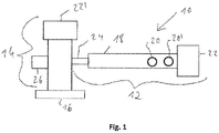
- the ones in the Figure 1 Mixing and kneading machine 10 according to the present invention, shown as a schematic top view, comprises a feed and mixing device 12, a discharge device 14 and an underwater granulation device 16.
- the feed and mixing device 12 comprises a housing 18, on the upper side of which a top feeder 20 and a Filling funnel 20 'for supplying the starting materials to be mixed and kneaded are arranged.
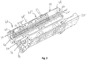
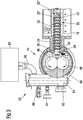
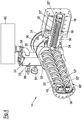
- the entry and mixing device 12 is shown in detail in a perspective view in opened form in FIG Figure 2 and the downstream end of the feeding and mixing device 12 - seen in the conveying direction - is shown in cross section in FIG Figures 3 and 4th shown.
- a drive block 22 is arranged, which comprises a motor and a transmission.
- the housing 18 comprises a connecting element 24 flanged to the downstream end of the housing face.
- a degassing device 26 is provided on the discharge device 14, namely on the side of the discharge device 14 opposite the connection element 24.
- the discharge device 14 also comprises a drive block 22 '. .
- the housing 18 comprises two housing halves 28, 28 ', which are lined on the inside with a so-called housing shell 30, which is composed of a plurality of axially adjacent housing shell parts 32, 32', 32 ".
- the housing shell 30 is referred to in the present patent application as Part of the housing 18.
- the inner circumferential surface of the housing 18 delimits, when the two housing halves 28, 28 'are closed, a cylindrical hollow interior in which a worm shaft 34 is arranged.
- the worm shaft 34 comprises a shaft rod 36, on its circumferential surface wing elements 38
- kneading elements 40 are provided, which are designed as kneading bolts 40.
- Each of these kneading elements is arranged for fixing in a bore provided in the wall of the housing 18, which extends from the inner circumferential surface the housing shell 30 through the wall of the housing 18 extends through.
- each receptacle 42 can have a square cross-section, with each kneading bolt 40 at its lower end having an end that fits precisely into the square-shaped, radially inner end of the receptacles 42 and is therefore non-rotatable in the receptacle 42 when inserted is fixed.
- the kneading bolt 40 is connected at its end lying in the receptacle 42 to a fixing element inserted in the overlying end of the receptacle 42 by screwing.
- the kneading bolts 40 which are equally spaced from one another, in each of the two housing halves 28, 28 ', viewed in the axial direction, are in the form of three rows 44, 44', 44 ".
- the housing 18 is preferably temperature-controllable by means of one or more thermal devices or with electric heating cartridges or heating plates attached to the outside of the housing and is water-cooled or air-cooled, optionally also cooled by another fluid, for example by an oil or another liquid or a special gas.
- the mixing and kneading machine is divided in the axial direction into several process sections 46, 46 ', 46 ", each process section 46, 46', 46" with regard to the number of kneading bolts 40 and the number and extent of the wing elements 38 on the Wave rod 34 is adapted to the function of the individual process sections 46, 46 ', 46 ".
- a degassing device 26 is provided at the downstream end of the housing 18, around the one made in the feeding and mixing device 12 to degas the mixture or melt prior to transfer into the outlet device 14 in order to remove gases and other volatile constituents such as residual moisture and monomers contained therein from the mixture or melt.
- Another disadvantage of this variant is that the mixture for degassing has to be in the form of a melt before it enters the discharge device, namely upstream of the connecting element 24 in the section of the housing 18 in which the degassing device 26 is provided, otherwise none effective degassing is possible.
- This also leads to the fact that the part of the feeding and mixing device 12 located downstream of the degassing device 26 and penetrated by the screw shaft 34 can only be used as a pure conveying section.
- this variant due to the lack of kneading elements 40 in the connecting element 24, complete cleaning of all flanks of the wing elements 38 of the worm shaft 34 is not possible.
- the degassing device 26 is provided on the discharge device 14 and, in addition, kneading elements 40 are also arranged on the inner circumferential surface of the connecting element 24 and extend into the interior of the connecting element 24.
- the degassing therefore no longer takes place in the area of the rapidly rotating and oscillating screw shaft 34 in the feed and mixing device 12, but in the discharge device 14, that is downstream of the rapidly rotating and oscillating screw shaft 34 of the feed and mixing device 12.
- the melt must first be formed further downstream so that the kneading elements 40 can also be arranged on the inner circumferential surface of the connecting element 24 without even thermally sensitive materials of the mixture processed therein, such as PVC, being thermally damaged.
- the length of the feeding and mixing device 12 can be shortened accordingly, whereby both the investment costs and the operating costs of the mixing and kneading machine 10 are considerably reduced.
- deposits on the flanks of the wing elements 38 and at the transition from the wing elements 38 to the shaft rod 36 of the worm shaft 34 also in the connecting element 24 are reliably avoided.
- the discharge device 14 is a counter-rotating twin-screw extruder, that is, one which has two mutually extending and interlocking screws 48, 48 'which rotate in opposite directions when the discharge device 14 is in operation.
- the screws 48, 48 ' have screw flights 50, 50' and shaft rods 52, 52 ', the screws 48, 48' being designed to correspond to one another and arranged in such a way that, when the two screws rotate, between the screw flights 50, 50 'and the shaft bars 52, 52' of the two screws 48, 48 'form chambers moving in the conveying direction.
- the two screws 48, 48 'of the twin screw extruder are not arranged parallel, but rather inclined at an angle of 0.1 to 20 °, preferably 0.5 to 10 ° and particularly preferably 2 to 5 ° are, wherein the two screws 48, 48 'converge in the conveying direction.
- the degassing device 26 of the discharge device 14 comprises a degassing dome 54 which is connected to the housing 56 of the discharge device 14 via an opening (not shown).
- a device 60 comprising a vacuum pump and a separator is arranged on the degassing dome 54 via a hose 58.
- the degassing dome 54 comprises a sight glass 62, a display 64 for negative pressure and a false air valve 66.
- the vacuum pump provided in the device 60 sets the required negative pressure in the degassing dome 54, whereas residual gas or residual liquid is set via the separator provided in the device 60 is withdrawn from the degassing dome 54 and separated.
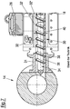
- the device 60 as in FIG Figure 5 shown as a continuous system or, as in the Figure 6 shown to be designed as a circulatory system.
- the device 60 shown configured as a flow system according to an exemplary embodiment of the present invention, comprises a water ring pump as a vacuum pump 68 and a separator 70, which are connected to one another via a hose line 72.
- the device 60 of this embodiment for fresh water supply comprises a water connection 74, a flow monitor 76, a 2/2 solenoid valve 78 and a throttle valve 80 for setting the amount of water.
- the device 60 shown configured as a circulatory system comprises a Water ring pump as vacuum pump 68 and a separator 70.
- the device 60 of this embodiment comprises a container with heat exchanger 81, a water connection 74 for fresh water supply, a dirt trap 82, a control valve 84, a 2/2 shut-off valve 86, a drain valve 88, and an overflow 90, a check valve 92 and a temperature regulator 94.
- the vacuum pump 68 sucks in the water from the container 81 and conveys the water and any components extracted from the mixture back into the container 81.
- the water in the container 81 is cooled by the heat exchanger.
- the water level in the container 81 is monitored and, if necessary, water is topped up. So that the container 81 cannot be overfilled, the pressureless overflow 90 is provided.
Landscapes
- Engineering & Computer Science (AREA)
- Mechanical Engineering (AREA)
- Life Sciences & Earth Sciences (AREA)
- Manufacturing & Machinery (AREA)
- Food Science & Technology (AREA)
- Animal Husbandry (AREA)
- Chemical & Material Sciences (AREA)
- Polymers & Plastics (AREA)
- Processing And Handling Of Plastics And Other Materials For Molding In General (AREA)
- Mixers Of The Rotary Stirring Type (AREA)
Description
Die vorliegende Erfindung betrifft eine Misch- und Knetmaschine für kontinuierliche Aufbereitungsprozesse mit einer Eintrags- und Mischvorrichtung, die ein Gehäuse umfasst, welche einen hohlen Innenraum begrenzt, in dem eine rotierende und sich vorzugsweise gleichzeitig translatorisch bewegende Schneckenwelle angeordnet ist, sowie mit einer Austragsvorrichtung, wie beispielsweise einem Austragsextruder.The present invention relates to a mixing and kneading machine for continuous preparation processes with a feed and mixing device which comprises a housing which delimits a hollow interior in which a rotating and preferably simultaneously translatory screw shaft is arranged, and with a discharge device such as for example a discharge extruder.
Derartige Misch- und Knetmaschinen werden insbesondere zum Aufbereiten von plastischen und/oder pastösen Massen eingesetzt. Beispielsweise dienen sie dem Verarbeiten von zähplastischen Massen, dem Homogenisieren und Plastifizieren von Kunststoffen, dem Einarbeiten von Füll- und Verstärkungsstoffen sowie dem Herstellen von Ausgangsmaterialien für die Lebensmittelindustrie. Die Schneckenwelle bildet hierbei das Arbeitsorgan, welches das zu verarbeitende Material in axialer Richtung vorwärts transportiert bzw. fördert und dabei die Komponenten des Materials miteinander vermischt.Mixing and kneading machines of this type are used in particular for the preparation of plastic and / or pasty materials. For example, they are used to process viscoplastic masses, homogenize and plasticize plastics, incorporate fillers and reinforcing materials, and manufacture raw materials for the food industry. The worm shaft here forms the working element which transports or conveys the material to be processed forward in the axial direction and thereby mixes the components of the material with one another.
Derartige Misch- und Knetmaschinen eignen sich insbesondere zum Herstellen von Polymergranulat, Polymerstrangpressprofilen, Polymerformteilen und dergleichen, wenn eine geeignete Austragsvorrichtung, wie beispielsweise ein Austragsextruder, eingesetzt wird und diese mit einer Granulationsvorrichtung oder einer ähnlichen Vorrichtung, wie mit einer intermittierenden Schneidvorrichtung, Strangdüse, Profilwerkzeug, Plattendüse oder einer ähnlichen Vorrichtung verbunden wird. Dabei wird durch die Eintrags- und Mischvorrichtung der Misch- und Knetmaschine eine homogene Polymerschmelze bzw. Mischung (beispielsweise von PVC, Gummi, Lebensmittel, Tierfutter, Pulverlack, halogenfreiem Flammschutzmittel, pharmazeutischen Stoffen etc.) erzeugt, welche dann in die Austragsvorrichtung und von dieser zu beispielsweise einer Granulationsvorrichtung gefördert wird. Beispielsweise werden die einzelnen Bestandteile der Mischung in dem vorderen Abschnitt der Eintrags- und Mischvorrichtung der Misch- und Knetmaschinen miteinander vermischt und homogenisiert und aus der so hergestellten homogenen Mischung eine Schmelze erzeugt (sofern wenigstens ein Bestandteil der Mischung schmelzfähig ist), wobei dasselbe in dem mittleren und in dem hinteren Abschnitt der Eintrags- und Mischvorrichtung geschieht. Die so erzeugte Schmelze wird dann durch die Austragsvorrichtung beispielsweise zu einer Unterwassergranulationsvorrichtung gefördert, in welcher die Schmelze mit beispielsweise 2 Millionen Pascal durch die Düsen einer Düsenplatte gepresst und direkt bei dem Austritt aus der Düsenplatte durch rotierende Messer zu Granulat geschnitten und durch über die Vorderseite der Düsenplatte fließendes Prozesswasser zu Granulatteilchen verfestigt wird. Alternativ dazu kann die Schmelze bzw. pastöse Mischung (wenn keine Schmelze erzeugt wird) auch durch ein Strangpress- oder Formteil-Werkzeug gepresst werden, um ein Polymerformteil herzustellen.Mixing and kneading machines of this type are particularly suitable for the production of polymer granules, extruded polymer profiles, molded polymer parts and the like, if a suitable discharge device, such as a discharge extruder, is used and this is combined with a granulation device or a similar device, such as an intermittent cutting device, strand die, profile tool , Plate nozzle or a similar device. The feeding and mixing device of the mixing and kneading machine creates a homogeneous polymer melt or mixture (for example of PVC, Rubber, food, animal feed, powder coating, halogen-free flame retardants, pharmaceutical substances, etc.), which is then conveyed into the discharge device and from there to, for example, a granulation device. For example, the individual components of the mixture are mixed with one another and homogenized in the front section of the feeding and mixing device of the mixing and kneading machines and a melt is produced from the homogeneous mixture produced in this way (provided that at least one component of the mixture is meltable), the same in the middle and in the rear section of the feeding and mixing device happens. The melt generated in this way is then conveyed through the discharge device, for example to an underwater granulation device, in which the melt is pressed through the nozzles of a nozzle plate with, for example, 2 million Pascals and cut into granules by rotating knives and through the front of the Nozzle plate flowing process water is solidified into granulate particles. As an alternative to this, the melt or pasty mixture (if no melt is generated) can also be pressed through an extrusion or molding tool in order to produce a polymer molding.
Die Eintrags- und Mischvorrichtungen solcher Misch- und Knetmaschinen sind beispielsweise aus der
Bei diesen Misch- und Knetmaschinen führt die Schneckenwelle der Eintrags- und Mischvorrichtung vorzugsweise nicht nur eine rotative Bewegung aus, sondern bewegt sich gleichzeitig auch in der axialen Richtung, d.h. in der Richtung der Schneckenwelle, translatorisch vor und zurück. Der Bewegungsablauf zeichnet sich daher vorzugsweise dadurch aus, dass die Schneckenwelle in der axialen Richtung gesehen eine der Rotation überlagerte oszillatorische Bewegung ausführt. Dieser Bewegungsablauf ermöglicht das Einbringen von Einbauten, nämlich von Knetelementen, wie von Knetbolzen oder von Knetzähnen, in das Gehäuse der Eintrags- und Mischvorrichtung. Wegen des Vorhandenseins der Knetbolzen oder der Knetzähne verläuft die auf der Hauptwelle, dem sogenannten Wellenstab, angeordnete Schnecke nicht - im Querschnitt des Wellenstabs gesehen - durchgehend, sondern ist in eine Mehrzahl von einzelnen Flügelelementen unterteilt, die sich jeweils über einen bestimmten Winkelabschnitt des Querschnittsumfangs des Wellenstabes erstrecken. Benachbarte Flügelelemente sind voneinander sowohl in axialer Richtung als auch in der Außenumfangsrichtung des Wellenstabes beabstandet, d.h. zwischen benachbarten Flügelelementen ist sowohl in axialer Richtung als auch in der Außenumfangsrichtung des Wellenstabes jeweils ein Spalt vorgesehen. Wenn beispielsweise der gesamte Wellenstab der Schneckenwelle oder ein axialer Abschnitt des Wellenstabs der Schneckenwelle, bezogen auf den Querschnittsumfang, drei Flügelelemente umfasst, welche sich jeweils über einen Winkelabschnitt von zum Beispiel 100° des Querschnittsumfangs des Wellenstabs erstrecken spricht man von einer dreiflügligen Schneckenwelle bzw. einem dreiflügligen Schneckenwellenabschnitt. Die Rotation und die translatorische Bewegung der Schneckenwelle in axialer Richtung werden so gesteuert, dass die einzelnen Flügelelemente mit ihren Flanken in die Nähe der entsprechenden Knetelemente gelangen, um das zu mischende und knetende Material zu verdichten und eine Scherwirkung auf dieses auszuüben, um so den Mischungs- und/oder Knetvorgang zu befördern, ohne dass die Knetelemente mit den Flügelelementen kollidieren. Abgesehen davon kommen die Knetelemente den Flanken der Flügelelemente so nahe, dass die Knetelemente Ablagerungen von Komponenten der Mischung auf den Flanken der Flügelelemente verhindert, so dass die Knetelemente im Ergebnis auch eine Reinigung der Flügelelemente bewirken. Natürlich muss die Anzahl und die Geometrie der Flügelelemente an die Anzahl der Knetelemente angepasst werden. Üblicherweise sind die einzelnen Knetelemente an der Innenumfangsfläche des Gehäuses der Eintrags- und Mischvorrichtung - in der axialen Richtung - in mehreren, auf die Geometrie und Anzahl der Flügelelemente abgestimmte und sich über zumindest einen Abschnitt der Innenumfangsfläche des Gehäuses erstreckenden Reihen angeordnet. Sind auf der Innenumfangsfläche des Gehäuses beispielsweise vier Reihen mit Knetelementen angeordnet, kann die Schneckenwelle auf deren Außenumfangsfläche - im Querschnitt gesehen - vier Flügelelemente aufweisen, zwischen denen jeweils ein genügend breiter Abstand vorsehen ist, damit sich die Knetelemente durch diese Abstände hindurchbewegen können.In these mixing and kneading machines, the screw shaft of the feeding and mixing device preferably not only performs a rotational movement, but also moves back and forth in translation in the axial direction, ie in the direction of the screw shaft. The movement sequence is therefore preferably characterized in that the worm shaft, viewed in the axial direction, executes an oscillatory movement superimposed on the rotation. This sequence of movements enables the introduction of internals, namely kneading elements such as kneading bolts or kneading teeth, into the housing of the feeding and mixing device. Because of the presence of kneading bolts or of the kneading teeth, the worm arranged on the main shaft, the so-called wave bar, does not run continuously - as seen in the cross section of the wave bar - but is divided into a plurality of individual wing elements, each extending over a certain angular section of the cross-sectional circumference of the wave bar. Adjacent wing elements are spaced from one another both in the axial direction and in the outer circumferential direction of the shaft rod, ie a gap is provided between adjacent wing elements both in the axial direction and in the outer circumferential direction of the shaft rod. If, for example, the entire shaft rod of the worm shaft or an axial section of the shaft rod of the worm shaft, based on the cross-sectional circumference, comprises three vane elements, which each extend over an angular section of, for example, 100 ° of the cross-sectional circumference of the shaft rod, one speaks of a three-bladed worm shaft or a three-bladed screw shaft section. The rotation and the translational movement of the worm shaft in the axial direction are controlled so that the flanks of the individual vane elements come close to the corresponding kneading elements in order to compact the material to be mixed and kneaded and to exert a shear effect on it to prevent the mixing - To convey and / or kneading process without the kneading elements colliding with the wing elements. Apart from this, the kneading elements come so close to the flanks of the wing elements that the kneading elements prevent components of the mixture from being deposited on the flanks of the wing elements, so that the kneading elements also effect cleaning of the wing elements. Of course, the number and geometry of the wing elements must be adapted to the number of kneading elements. The individual kneading elements are usually arranged on the inner circumferential surface of the housing of the feeding and mixing device - in the axial direction - in several rows that are matched to the geometry and number of the wing elements and extend over at least a portion of the inner circumferential surface of the housing. For example, there are four rows on the inner peripheral surface of the housing Arranged kneading elements, the screw shaft can on its outer circumferential surface - seen in cross section - have four wing elements, between which a sufficiently wide spacing is provided so that the kneading elements can move through these distances.
Wie dargelegt, ist an dem - in Förderrichtung gesehen - stromabwärtigen Ende der Eintrags- und Mischvorrichtung der Misch- und Knetmaschine eine Austragsvorrichtung angeordnet, um die in der Eintrags- und Mischvorrichtung hergestellte homogene Mischung zur weiteren Verarbeitung aus der Eintrags- und Mischvorrichtung heraus und beispielsweise in eine weitere Verarbeitungsvorrichtung, wie beispielsweise eine Granulationsvorrichtung, hinein zu fördern. Zur Verbindung des Gehäuses der Eintrags- und Mischvorrichtung mit der Austragsvorrichtung, ist typischerweise an dem, in Förderrichtung gesehen, stromabwärtigen stirnseitigen Ende des Gehäuses der Eintrags- und Mischvorrichtung ein Verbindungselement angeordnet. In der Regel ist das Verbindungselement ein Flansch. Zweck des Verbindungselementes ist es, das stromabwärtige Ende des Gehäuses und die Eingangsseite der Austrittsvorrichtung so miteinander zu verbinden, dass die Mischung aus der Eintrags- und Mischvorrichtung so in die Austragsvorrichtung gefördert werden kann, dass diese dort weitergefördert werden kann, ohne dass diese bei der Überführung durch mechanische oder thermische Einflüsse geschädigt wird. Zu diesem Zweck erstreckt sich die in dem Gehäuse der Eintrags- und Mischvorrichtung angeordnete Schneckenwelle durch das Verbindungselement hindurch, um die Mischung durch das Verbindungselement direkt bis zu der Austrittsvorrichtung zu fördern.As explained, a discharge device is arranged at the downstream end of the feeding and mixing device of the mixing and kneading machine - seen in the conveying direction - in order to remove the homogeneous mixture produced in the feeding and mixing device for further processing from the feeding and mixing device and for example to convey into a further processing device, such as a granulation device. To connect the housing of the feeding and mixing device to the discharge device, a connecting element is typically arranged at the downstream end of the housing of the feeding and mixing device, seen in the conveying direction. Usually the connecting element is a flange. The purpose of the connecting element is to connect the downstream end of the housing and the inlet side of the outlet device with each other in such a way that the mixture from the feed and mixing device can be conveyed into the discharge device in such a way that it can be conveyed further there without it being fed during the Transfer is damaged by mechanical or thermal influences. For this purpose, the screw shaft arranged in the housing of the feed and mixing device extends through the connecting element in order to convey the mixture through the connecting element directly to the outlet device.
Bei den bekannten Misch- und Knetmaschinen wird die in der Eintrags- und Mischvorrichtung hergestellte Mischung bzw. Schmelze vor der Überführung in die Austrittsvorrichtung entgast, um aus der Mischung bzw. Schmelze darin enthaltende Gase und andere leicht flüchtige Bestandteile, wie Restfeuchtigkeit und Monomere, zu entfernen. Bei einer Variante bekannter Misch- und Knetmaschinen ist hierzu an dem - in Förderrichtung gesehen - stromabwärtigen Ende des Gehäuses der Eintrags- und Mischvorrichtung eine Entgasungsvorrichtung vorgesehen, welche einen Unterdruck an die Schmelze bzw. die Mischung (wenn keine Schmelze erzeugt wird) anlegt, um so die flüchtigen Bestandteile aus der Schmelze bzw. die Mischung (wenn keine Schmelze erzeugt wird) abzuziehen. Dies hat jedoch mehrere Nachteile, und zwar insbesondere bei thermisch empfindlichen Schmelzen bzw. Mischungen. Zum einen können dann stromabwärts der Entgasungsvorrichtung, d.h. in dem allerletzten Abschnitt des Gehäuses und in dem Verbindungselement, keine Knetelemente mehr eingesetzt werden, da ansonsten zu viel Energie in die bereits entgaste Schmelze bzw. die Mischung (wenn keine Schmelze erzeugt wird) eingeführt werden würde, was zu einem Temperaturanstieg der Schmelze und aus diesem Grund zu einer thermischen Schädigung der entgasten Schmelze führen würde. Aus diesem Grund werden in den bekannten Misch- und Knetmaschinen dieser Variante in dem stromabwärts der Entgasungsvorrichtung gelegenen Abschnitt des Gehäuses und vor allem in dem Verbindungselement keine Knetelemente mehr vorgesehen, was dazu führt, dass der stromabwärtige Bereich der Eintrags- und Mischvorrichtung, in welchem keine Knetelemente mehr vorgesehen sind, für die Vermischung der Bestandteile der Mischung und Homogenisierung der Mischung zumindest weitgehend verlorengeht. Vielmehr handelt es sich hierbei nur noch um einen reinen Förderabschnitt. Ein weiterer Nachteil dieser Variante ist es, dass die Mischung zum Entgasen bereits vor dem Eintritt in die Austragsvorrichtung, nämlich bereits stromaufwärts des Verbindungselements in dem Abschnitt des Gehäuses, in dem die Entgasungsvorrichtung vorgesehen ist, als Schmelze bzw. die Mischung (wenn keine Schmelze erzeugt wird) vorliegen muss, da sonst keine wirksame Entgasung möglich ist. Auch dies führt dazu, dass der stromabwärts der Entgasungsvorrichtung liegende, von der Schneckenwelle durchdrungene Teil der Eintrags- und Mischvorrichtung der Misch- und Knetmaschine nur noch als reiner Förderabschnitt genutzt werden kann. Zudem wird die Schmelze in dem stromabwärtigen Verbindungselement - trotz des Fehlens von Knetelementen - weiter geschert, was zu einer Erhöhung der Schmelzetemperatur oder gar zu einer thermischen Schädigung der Schmelze, wie insbesondere bei thermisch sensitiven Materialien, wie Polyvinylchlorid (PVC), führen kann. Abgesehen davon ist bei dieser Variante aufgrund des Fehlens von Knetelementen in dem Verbindungselement eine vollständige Abreinigung aller Flanken der Flügelelemente der Schneckenwelle nicht möglich. Dies führt zu Ablagerungen an den Flanken der Flügelelemente und am Übergang der Flügelelemente zu dem Wellenstab. Dies wiederum führt dazu, dass bei einem Wechsel der Ausgangsmaterialien die Spülzeiten für die Misch- und Knetmaschine lang und die Menge des Abfallmaterials groß wird, da der durch die Knetbolzen erzielte "Selbstreinigungseffekt" fehlt. Nicht selten muss die gesamte Eintrags- und Mischvorrichtung der Misch- und Knetmaschine geöffnet und gereinigt werden, um die Abfallmengen zu vermeiden oder, falls Spülen nicht erfolgreich angewendet werden kann, den Wechsel der Ausgangsmaterialien überhaupt erst möglich zu machen.In the known mixing and kneading machines, the mixture or melt produced in the feed and mixing device is degassed before transfer to the outlet device in order to remove gases and other volatile constituents such as residual moisture and monomers contained in the mixture or melt remove. In a variant of known mixing and kneading machines, this is at the - viewed in the conveying direction - downstream end of the Housing of the feeding and mixing device a degassing device is provided, which applies a negative pressure to the melt or the mixture (if no melt is generated) in order to draw off the volatile constituents from the melt or the mixture (if no melt is generated). However, this has several disadvantages, particularly in the case of thermally sensitive melts or mixtures. On the one hand, kneading elements can no longer be used downstream of the degassing device, ie in the very last section of the housing and in the connecting element, since otherwise too much energy would be introduced into the melt or mixture that has already been degassed (if no melt is generated) which would lead to an increase in the temperature of the melt and, for this reason, to thermal damage to the degassed melt. For this reason, in the known mixing and kneading machines of this variant, no kneading elements are provided in the section of the housing located downstream of the degassing device and especially in the connecting element, which means that the downstream area of the feeding and mixing device, in which none Kneading elements are more provided for the mixing of the constituents of the mixture and homogenization of the mixture is at least largely lost. Rather, this is only a pure conveying section. Another disadvantage of this variant is that the mixture for degassing already before entering the discharge device, namely already upstream of the connecting element in the section of the housing in which the degassing device is provided, as a melt or the mixture (if no melt is generated will) must be present, otherwise no effective degassing is possible. This also leads to the fact that the part of the feeding and mixing device of the mixing and kneading machine located downstream of the degassing device and penetrated by the screw shaft can only be used as a pure conveying section. In addition, the melt in the downstream connecting element - despite the lack of kneading elements - is sheared further, which leads to an increase in the melt temperature or even to a thermal one Damage to the melt, especially in the case of thermally sensitive materials such as polyvinyl chloride (PVC). Apart from this, in this variant, due to the lack of kneading elements in the connecting element, complete cleaning of all flanks of the wing elements of the worm shaft is not possible. This leads to deposits on the flanks of the wing elements and at the transition between the wing elements and the wave bar. This in turn means that when the starting materials are changed, the rinsing times for the mixing and kneading machine become long and the amount of waste material large, since the "self-cleaning effect" achieved by the kneading bolts is missing. It is not uncommon for the entire feeding and mixing device of the mixing and kneading machine to be opened and cleaned in order to avoid the amount of waste or, if flushing cannot be used successfully, to make it possible to change the starting materials in the first place.
Bei einer anderen Variante bekannter Misch- und Knetmaschinen wird zur Entgasung zwischen dem Verbindungselement der Eintrags- und Mischvorrichtung und der Austragsvorrichtung ein Entgasungsdom vorgesehen, bei dem die Mischung nach dem Austrag aus der Eintrags- und Mischvorrichtung von oben in einen zylindrischen Turm eingeführt wird und in diesem nach unten auf die Schnecke der Austragsvorrichtung fällt. Allerdings ist diese Variante für die Prozessierung von Schmelze wenig bzw. gar nicht geeignet. Abgesehen davon muss die Schnecke der Austragsvorrichtung sehr groß dimensioniert werden, um alles in den Entgasungsdom fallende Material aus diesem heraus zu fördern. Dies führt zu hohen Investitionskosten dieser Variante.In another variant of known mixing and kneading machines, a degassing dome is provided for degassing between the connecting element of the feed and mixing device and the discharge device, in which the mixture is introduced from above into a cylindrical tower after discharge from the feed and mixing device and into this falls down onto the screw of the discharge device. However, this variant is little or not at all suitable for processing melt. Apart from this, the screw of the discharge device must be dimensioned very large in order to convey all material falling into the degassing dome out of it. This leads to high investment costs for this variant.
In der
Ausgehend davon liegt die Aufgabe der vorliegenden Erfindung daher darin, eine für kontinuierliche Aufbereitungsprozesse, wie insbesondere zur Herstellung von Granulat, Strangpressprofilen oder Formteilen, wie Polymergranulat, Polymerstrangpressprofilen oder Polymerformteilen, geeignete Misch- und Knetmaschine bereitzustellen, welche eine optimale Vermischung und Homogenisierung der Bestandteile der Mischung bei einer minimalen Länge der Eintrags- und Mischvorrichtung ermöglicht, so dass sich die Misch- und Knetmaschine durch einen optimalen Wirkungsgrad in Bezug auf Länge der Eintrags- und Mischvorrichtung auszeichnet, und, welche zudem bei einem Wechsel der in die Misch- und Knetmaschine eingesetzten Ausgangsstoffe eine Selbstreinigung der Eintrags- und Mischvorrichtung erleichtert.Based on this, the object of the present invention is therefore to provide a mixing and kneading machine that is suitable for continuous preparation processes, such as in particular for the production of granules, extruded profiles or molded parts such as polymer granules, polymer extruded profiles or polymer molded parts, which allows optimal mixing and homogenization of the components of the Mix at a minimum length of the Feeding and mixing device allows, so that the mixing and kneading machine is characterized by an optimal degree of efficiency in relation to the length of the feeding and mixing device, and which, in addition, when the starting materials used in the mixing and kneading machine are changed, self-cleaning of the feed and mixing device facilitated.
Erfindungsgemäß wird diese Aufgabe durch eine Misch- und Knetmaschine nach Anspruch 1 für kontinuierliche Aufbereitungsprozesse, wie zur Herstellung von Granulat, Strangpressprofilen oder Formteilen, wie Polymergranulat, Polymerstrangpressprofilen oder Polymerformteilen, mit einer Eintrags- und Mischvorrichtung und mit einer Austragsvorrichtung gelöst, bei welcher die Eintrags- und Mischvorrichtung ein Gehäuse, eine Schneckenwelle und ein Verbindungselement umfasst, wobei das Verbindungselement an einer Stirnseite des Gehäuses angeordnet ist und zudem mit der Austragsvorrichtung verbunden ist, wobei sowohl in dem Gehäuse als auch in dem Verbindungselement jeweils ein hohler Innenraum ausgebildet ist und sich die Schneckenwelle zumindest abschnittsweise in axialer Richtung durch den Innenraum des Gehäuses sowie zumindest abschnittsweise in axialer Richtung durch den Innenraum des Verbindungselements erstreckt, wobei in dem Gehäuse eine Vielzahl von Knetelementen vorgesehen ist, welche sich von der Innenumfangsfläche des Gehäuses in den Innenraum hinein erstrecken, und wobei die Misch- und Knetmaschine dadurch gekennzeichnet ist, dass auch an der Innenumfangsfläche des Verbindungselements Knetelemente angeordnet sind, welche sich in den Innenraum des Verbindungselements hinein erstrecken, und die Austragsvorrichtung eine Entgasungsvorrichtung aufweist.According to the invention, this object is achieved by a mixing and kneading machine according to claim 1 for continuous preparation processes, such as for the production of granules, extruded profiles or molded parts, such as polymer granules, polymer extruded profiles or polymer molded parts, with an entry and mixing device and with a discharge device in which the entry - and mixing device comprises a housing, a worm shaft and a connecting element, wherein the connecting element is arranged on an end face of the housing and is also connected to the discharge device, wherein a hollow interior is formed in both the housing and in the connecting element and the The worm shaft extends at least in sections in the axial direction through the interior of the housing and at least in sections in the axial direction through the interior of the connecting element, a plurality of kneading elements being provided in the housing, which s I extend from the inner circumferential surface of the housing into the interior, and the mixing and kneading machine is characterized in that kneading elements are also arranged on the inner circumferential surface of the connecting element, which kneading elements extend into the interior of the connecting element, and the discharge device has a degassing device .
Diese Lösung beruht auf der Erkenntnis, dass durch das Anordnen der Entgasungsvorrichtung erst an der Austragsvorrichtung anstelle von an dem, in Förderrichtung gesehen, stromabwärtigen Ende des Gehäuses der Eintrags- und Mischvorrichtung, die Schmelze bzw. Mischung (wenn keine Schmelze erzeugt wird) erst weiter stromabwärts ausgebildet werden muss, so dass die Knetelemente auch an der Innenumfangsfläche des Verbindungselements angeordnet werden können, ohne dass selbst thermisch sensitive Materialien der darin prozessierten Mischung, wie PVC, thermisch geschädigt werden. Die Entgasung findet bei der erfindungsgemäßen Misch- und Knetmaschine nicht mehr in dem Bereich der sich schnell rotierenden und oszillierenden Schneckenwelle in der Eintrags- und Mischvorrichtung statt, sondern in der Austragsvorrichtung, also stromabwärts der sich schnell rotierenden und oszillierenden Schneckenwelle der Eintrags- und Mischvorrichtung. Durch das Anordnen von Knetelementen auch an der Innenumfangsfläche des Verbindungselements steht auch dieser Bereich der Eintrags- und Mischvorrichtung für die Vermischung der Bestandteile der Mischung und für die Homogenisierung der Mischung zur Verfügung, so dass die Länge des Eintrags- und Mischvorrichtung entsprechend verkürzt werden kann, um dennoch den gleichen Misch- und Homogenisierungsgrad wie bei einer entsprechend längeren Eintrags- und Mischvorrichtung, bei der das Verbindungselement keine Knetelemente aufweist, zu erreichen. Somit werden nicht nur die Investitionskosten der Misch- und Knetmaschine erheblich verringert, sondern insbesondere auch die Betriebskosten, da die Eintrags- und Mischvorrichtung aufgrund ihrer geringeren Gesamtlänge weniger Verschleiß sowie einen geringeren Platzbedarf aufweist. Wie dargelegt ist es bei der erfindungsgemäßen Misch- und Knetmaschine auch ausreichend, wenn Schmelze bzw. Mischung (wenn keine Schmelze erzeugt wird) verarbeitet werden soll, dass die Schmelze bzw. Mischung (wenn keine Schmelze erzeugt wird) erst am, in Förderrichtung gesehen, stromabwärtigen des Verbindungselements ausgebildet ist. Auch dies trägt dazu bei, dass die Gesamtlänge des Eintrags- und Mischvorrichtung der Misch- und Knetmaschine, bei gleichem Misch- und Homogenisierungsgrad, signifikant verringert werden kann. Abgesehen davon erlaubt die erfindungsgemäße Misch- und Knetmaschine aufgrund des Vorsehens von Knetelementen auch in dem Verbindungselement eine vollständige Abreinigung aller Flanken der Flügelelemente der Schneckenwelle bis zu deren stromabwärtigen Ende. Dadurch werden Ablagerungen an den Flanken der Flügelelemente und am Übergang der Flügelelemente zu dem Wellenstab der Schneckenwelle auch in dem Verbindungselement zuverlässig vermieden. Dies führt auch dazu, dass bei einem Wechsel der Ausgangsmaterialien die Spülzeiten für die Misch- und Knetmaschine drastisch verkürzt werden. Alles in allem stellt die vorliegende Erfindung eine für kontinuierliche Aufbereitungsprozesse, wie insbesondere zur Herstellung von Granulat, Strangpressprofilen oder Formteilen, wie Polymergranulat, Polymerstrangpressprofilen oder Polymerformteilen, geeignete Misch- und Knetmaschine bereit, welche eine optimale Vermischung und Homogenisierung der Ausgangsstoffe der Mischung bei einer minimalen Länge der Eintrags- und Mischvorrichtung ermöglicht, so dass sich die Misch- und Knetmaschine durch einen optimalen Wirkungsgrad in Bezug auf Länge der Eintrags- und Mischvorrichtung auszeichnet, und, welche zudem bei einem Wechsel der in die Misch- und Knetmaschine eingesetzten Bestandteile eine Reinigung der Eintrags- und Mischvorrichtung erleichtert.This solution is based on the knowledge that by arranging the degassing device only on the discharge device instead of on the downstream end of the housing of the feed and mixing device, seen in the conveying direction, the melt or mixture (if no melt is generated) only continues must be formed downstream so that the kneading elements can also be arranged on the inner peripheral surface of the connecting element without even thermally sensitive materials of the mixture processed therein, such as PVC, being thermally damaged. In the mixing and kneading machine according to the invention, degassing no longer takes place in the area of the rapidly rotating and oscillating screw shaft in the feed and mixing device, but in the discharge device, i.e. downstream of the rapidly rotating and oscillating screw shaft of the feed and mixing device. By arranging kneading elements on the inner circumferential surface of the connecting element, this area of the feeding and mixing device is also available for mixing the components of the mixture and for homogenizing the mixture, so that the length of the feeding and mixing device can be shortened accordingly, in order to nevertheless achieve the same degree of mixing and homogenization as with a correspondingly longer feeding and mixing device in which the connecting element has no kneading elements. Thus, not only the investment costs of the mixing and kneading machine are considerably reduced, but also, in particular, the operating costs, since the feeding and mixing device has less wear and less space due to its shorter overall length. As explained, it is also sufficient with the mixing and kneading machine according to the invention if the melt or mixture (if no melt is generated) is to be processed, that the melt or mixture (if no melt is generated) only on, viewed in the conveying direction, is formed downstream of the connecting element. This also contributes to the fact that the total length of the feeding and mixing device of the mixing and kneading machine can be significantly reduced with the same degree of mixing and homogenization. Apart from this, the mixing and kneading machine according to the invention allows, due to the provision of kneading elements also in the connecting element, a complete cleaning of all flanks of the vane elements of the worm shaft up to its downstream end. This causes deposits on the flanks of the wing elements and at the transition between the wing elements and the wave bar Worm shaft reliably avoided in the connecting element. This also means that the rinsing times for the mixing and kneading machine are drastically reduced when the starting materials are changed. All in all, the present invention provides a mixing and kneading machine suitable for continuous preparation processes, such as in particular for the production of granules, extruded profiles or molded parts, such as polymer granules, polymer extruded profiles or polymer molded parts, which optimally mixes and homogenizes the starting materials of the mixture with a minimum Length of the entry and mixing device allows, so that the mixing and kneading machine is characterized by an optimal efficiency in relation to the length of the entry and mixing device, and which also cleaning the components used in the mixing and kneading when changing Entry and mixing device facilitated.
Gemäß einer besonders bevorzugten Ausführungsform der vorliegenden Erfindung ist die Austragsvorrichtung ein vorzugsweise gegenläufiger Doppelschneckenextruder. Bei einem Doppelschneckenextruder bilden sich bei der Drehung beider Schnecken zwischen den Schnecken Kammern aus, durch welche die Mischung in der Austragsvorrichtung nach vorne gefördert wird. Dies deshalb, weil die Schneckenstege und die Wellenstäbe der Schnecken von Doppelschneckenextrudern derart korrespondierend zueinander ausgebildet und ineinandergreifend angeordnet sind, dass sich bei der Rotation der beiden Schnecken zwischen den Schneckenstegen und Wellenstäben der beiden Schnecken in der Förderrichtung wandernde Kammern ausbilden. Es ergibt sich somit eine Zwangsförderung, die es erlaubt, die beiden Schnecken langsam zu rotieren und dennoch die Mischung zuverlässig durch die Austragsvorrichtung zu fördern, so dass nur ein geringfügiger Rückfluss eines Teils der Mischung entgegen der Förderrichtung erfolgt. Aufgrund der langsamen Rotation der beiden Schnecken weist die Mischung in der Austragsvorrichtung, also in dem Bereich der Entgasung, eine vergleichsweise große Verweilzeit und Entgasungsoberfläche auf, so dass eine effiziente Entgasung erreicht wird, ohne dass hohe Scherkräfte in die Mischung eingebracht werden. Dadurch werden thermische Schädigungen der Mischung zuverlässig vermieden. Somit wirkt die in die Austragsvorrichtung verlagerte Entgasungsvorrichtung mit der bevorzugten Ausgestaltung der Austragsvorrichtung als gegenläufiger Doppelschneckenextruder synergistisch zusammen. Ein weiterer Vorteil des Doppelschneckenextruders ist, dass Ablagerungen von Mischungsbestandteilen an der Schneckenwelle im Vergleich zu einem Einwellenextruder signifikant verringert sind, da die Schneckenstege bei dem Doppelschneckenextruder ineinandergreifen.According to a particularly preferred embodiment of the present invention, the discharge device is a preferably counter-rotating twin-screw extruder. In a twin screw extruder, chambers are formed between the screws when the two screws rotate, through which the mixture is conveyed to the front in the discharge device. This is because the screw flights and the shaft rods of the screws of twin-screw extruders are designed to correspond to one another and are interlocking in such a way that when the two screws rotate, chambers that move in the conveying direction are formed between the screw flights and shaft rods of the two screws. This results in a forced conveyance that allows the two screws to rotate slowly and yet convey the mixture reliably through the discharge device, so that only a slight backflow of part of the mixture occurs against the conveying direction. Due to the slow rotation of the two screws, the mixture in the discharge device, i.e. in the area of the degassing, has a comparatively long residence time and degassing surface, so that efficient degassing is achieved without high shear forces in the mixture be introduced. This reliably prevents thermal damage to the mixture. The degassing device shifted into the discharge device thus works synergistically with the preferred configuration of the discharge device as a counter-rotating twin-screw extruder. Another advantage of the twin-screw extruder is that deposits of mixture components on the screw shaft are significantly reduced in comparison with a single-screw extruder, since the screw flights in the twin-screw extruder intermesh.
Besonders gute Ergebnisse werden diesbezüglich erreicht, wenn die Austragsvorrichtung ein gegenläufiger Doppelschneckenextruder ist. Diese haben den Vorteil eines hohen Druckaufbauvermögens von 250 bis 300 bar auf 2 bis 3 D Schneckenlänge (also auf einer dem zwei- bis dreifachen des Schneckenwellendurchmessers entsprechenden Länge) bei gleichzeitig geringfügiger Temperaturerhöhung der Schmelze bzw. Mischung (wenn keine schmelze erzeugt wird). Im Gegensatz dazu drehen gleichläufige Doppelschneckenextruder schnell, weswegen diese eine höhere Scherung ausüben und deutlich weniger Druck aufbauen als gegenläufige Doppelschneckenextruder.Particularly good results are achieved in this regard if the discharge device is a counter-rotating twin-screw extruder. These have the advantage of a high pressure build-up capacity of 250 to 300 bar over a 2 to 3 D screw length (i.e. over a length corresponding to two to three times the screw shaft diameter) with a simultaneous slight increase in the temperature of the melt or mixture (if no melt is generated). In contrast, co-rotating twin-screw extruders rotate quickly, which is why they exert higher shear and build up significantly less pressure than counter-rotating twin-screw extruders.
Die Schnecken des gegenläufigen Doppelschneckenextruders können parallel zueinander angeordnet sein.The screws of the counter-rotating twin screw extruder can be arranged parallel to one another.
In Weiterbildung des Erfindungsgedankens wird es vorgeschlagen, dass die beiden Schnecken des Doppelschneckenextruders, in axialer Richtung gesehen, um einem Winkel von 0,1 bis 10°, bevorzugt 0,5 bis 7,5°, besonders bevorzugt 2 bis 5° und höchst bevorzugt 2 bis 3° zueinander geneigt angeordnet, wobei vorzugsweise die beiden Schnecken in der Förderrichtung zusammenlaufen. Bei dieser Ausführungsform kann die Gangtiefe über die Schneckenlänge in Förderrichtung abnehmend oder gleichbleibend ausgebildet werden. Bei einer solchen Ausgestaltung der Schnecken des Doppelschneckenextruders werden die bei dem Betrieb der Austragsvorrichtung zwischen den beiden Schnecken ausgebildeten Kammern in der Förderrichtung sukzessive kleiner bzw. nimmt das Volumen dieser Kammern ab. Dadurch wird die in den Kammern geförderte Mischung in der Förderrichtung zunehmend komprimiert, so dass in der Mischung verbliebene flüchtige Verbindungen, wie insbesondere Gas, Restfeuchte und Monomere, entgegen der Förderrichtung der Austragsvorrichtung, also zu der Entgasungsvorrichtung hin, gedrückt werden. Dies unterstützt die Entgasung entscheidend, so dass das synergistisch Zusammenwirken der in die Austragsvorrichtung verlagerten Entgasungsvorrichtung mit der Ausgestaltung der Austragsvorrichtung als Doppelschneckenextruder sogar noch gesteigert wird.In a further development of the inventive concept, it is proposed that the two screws of the twin screw extruder, seen in the axial direction, at an angle of 0.1 to 10 °, preferably 0.5 to 7.5 °, particularly preferably 2 to 5 ° and most preferably 2 to 3 ° inclined to each other, the two screws preferably converging in the conveying direction. In this embodiment, the flight depth can be designed to be decreasing or constant over the length of the screw in the conveying direction. With such a configuration of the screws of the twin screw extruder, the Operation of the discharge device between the two screws formed chambers successively smaller in the conveying direction or the volume of these chambers decreases. As a result, the mixture conveyed in the chambers is increasingly compressed in the conveying direction, so that volatile compounds remaining in the mixture, such as in particular gas, residual moisture and monomers, are pressed against the conveying direction of the discharge device, i.e. towards the degassing device. This decisively supports the degassing, so that the synergistic interaction of the degassing device relocated into the discharge device with the configuration of the discharge device as a twin-screw extruder is even increased.
Gemäß einer weiteren bevorzugten Ausführungsform der vorliegenden Erfindung ist es vorgesehen, dass die Schnecken der Austragsvorrichtung konisch verlaufen, wobei sich die Schnecken in der Förderrichtung verjüngen. Dies unterstützt den Effekt der vorgenannten Ausführungsform, bei der die beiden Schnecken des Doppelschneckenextruders, in axialer Richtung gesehen, nicht parallel, sondern um einem Winkel zueinander geneigt angeordnet sind.According to a further preferred embodiment of the present invention, it is provided that the screws of the discharge device run conically, the screws tapering in the conveying direction. This supports the effect of the aforementioned embodiment, in which the two screws of the twin screw extruder, viewed in the axial direction, are not arranged parallel, but rather inclined to one another at an angle.
Um eine platzsparende und bezüglich der Länge der Gesamtmaschine signifikant verkürzte Misch- und Knetmaschine zu erreichen, wird es in Weiterbildung des Erfindungsgedankens vorgeschlagen, die beiden Schnecken (bezogen auf ihre axiale Längsrichtung) der Austragsvorrichtung in der horizontalen Ebene in Bezug auf die Schneckenwelle der Eintrags- und Mischvorrichtung um 45° bis 135°, bevorzugt um 60° bis 120°, besonders bevorzugt um 80° bis 100°, ganz besonders bevorzugt um 85° bis 95° und höchst bevorzugt um 90° zu verdrehen, so dass das stirnseitige Ende der sich in dem Verbindungselement erstreckenden Schneckenwelle zu den Außenumfangsflächen der Schnecken der Austragsvorrichtung hin gerichtet sind. Dadurch ist die Austragsvorrichtung rechtwinklig zu der Eintrags- und Mischvorrichtung angeordnet. Neben der dadurch erreichten Platzersparnis hat diese Ausführungsform den Vorteil, dass die in der Eintrags- und Mischvorrichtung hergestellte Mischung von der Schneckenwelle aus dem dem Gehäuse der Eintrags- und Mischvorrichtung gegenüberliegenden Ende des Verbindungselements direkt zwischen die beiden Schnecken der Austragsvorrichtung gefördert werden kann. Dadurch wird ein wirksamer Übergang der Mischung von der Eintrags- und Mischvorrichtung in die Austragsvorrichtung erreicht, was sicherstellt, dass sich nicht Bestandteile der Mischung an anderen Bauteilen absetzen oder dort anbacken. Indem die Entgasungsvorrichtung an der gegenüberliegenden Seite der Austragsvorrichtung angeordnet werden kann, kann zudem die Entgasung direkt bei dem Eintritt der Mischung in die Austragsvorrichtung erfolgen.In order to achieve a space-saving mixing and kneading machine that is significantly shorter in terms of the length of the overall machine, it is proposed in a further development of the inventive concept that the two screws (with respect to their axial longitudinal direction) of the discharge device in the horizontal plane with respect to the screw shaft of the entry and mixing device by 45 ° to 135 °, preferably by 60 ° to 120 °, particularly preferably by 80 ° to 100 °, very particularly preferably by 85 ° to 95 ° and most preferably by 90 °, so that the front end of the in the connecting element extending screw shaft are directed towards the outer peripheral surfaces of the screws of the discharge device. As a result, the discharge device is arranged at right angles to the feed and mixing device. In addition to the space savings achieved in this way, this embodiment has the advantage that the mixture produced in the feed and mixing device starts from the screw shaft the end of the connecting element opposite the housing of the feeding and mixing device can be conveyed directly between the two screws of the discharge device. As a result, an effective transition of the mixture from the feed and mixing device into the discharge device is achieved, which ensures that components of the mixture do not settle on other components or stick to them. Since the degassing device can be arranged on the opposite side of the discharge device, the degassing can also take place directly when the mixture enters the discharge device.
Wie dargelegt, sind erfindungsgemäß auch an der Innenumfangsfläche des Verbindungselements der Eintrags- und Mischvorrichtung Knetelemente angeordnet, welche sich in den Innenraum des Verbindungselements hinein erstrecken und dort zusammen mit den auf dem Wellenstab der Schneckenwelle angeordneten Flügelelementen nicht nur eine optimale Vermischung und Homogenisierung der durch die Schneckenwelle geförderten Mischung bewirkt, sondern insbesondere auch eine Ablagerung bzw. ein Anbacken von Bestandteilen der Mischung an den Flanken der Flügelelemente und insbesondere am Übergang der Flanken der Flügelelemente zu der Außenumfangsfläche des Wellenstabs verhindert. Vorzugsweise erstrecken sich die Knetelemente - in der axialen Richtung des Verbindungselements gesehen - weit in das Verbindungselement hinein, um so die Länge des Verbindungselements für das Vermischen und Homogenisieren der Mischung möglichst gut zu nutzen. Zudem ist es bevorzugt, dass die Knetelemente an der Innenumfangsfläche des Verbindungselements in zumindest zwei sich in der axialen Richtung über zumindest einen Abschnitt der Innenumfangsfläche des Verbindungselements erstreckenden Reihen angeordnet sind, um so den Einsatz eines mehrflügligen Schneckenwellenabschnitts in dem Verbindungselement zu erlauben. Vorzugsweise deckt der Abstand von dem ersten bis letzten Knetelement wenigstens einer Reihe in dem Verbindungselement wenigstens 50%, bevorzugt wenigstens 70%, besonders bevorzugt wenigstens 80%, ganz besonders bevorzugt wenigstens 90% und höchst bevorzugt die gesamte axiale Länge der Innenumfangsfläche des Verbindungselements ab. Bevorzugt decken die Abstände von dem ersten bis letzten Knetelement aller Reihen in dem Verbindungselement wenigstens 50%, bevorzugt wenigstens 70%, besonders bevorzugt wenigstens 80%, ganz besonders bevorzugt wenigstens 90% und höchst bevorzugt die gesamte axiale Länge der Innenumfangsfläche des Verbindungselements ab.As explained, according to the invention, kneading elements are also arranged on the inner circumferential surface of the connecting element of the feeding and mixing device, which extend into the interior of the connecting element and there, together with the wing elements arranged on the shaft rod of the worm shaft, not only optimal mixing and homogenization of the Screw shaft promoted mixture causes, but in particular also prevents deposition or caking of components of the mixture on the flanks of the wing elements and in particular at the transition of the flanks of the wing elements to the outer circumferential surface of the shaft rod. The kneading elements preferably extend - viewed in the axial direction of the connecting element - far into the connecting element in order to make the best possible use of the length of the connecting element for mixing and homogenizing the mixture. In addition, it is preferred that the kneading elements are arranged on the inner circumferential surface of the connecting element in at least two rows extending in the axial direction over at least a portion of the inner circumferential surface of the connecting element, so as to allow the use of a multi-wing worm shaft section in the connecting element. The distance from the first to the last kneading element covers at least one row in the connecting element at least 50%, preferably at least 70%, particularly preferably at least 80%, very particularly preferably at least 90% and most preferably the total axial length of the inner peripheral surface of the connecting element. Preferably, the distances from the first to last kneading element of all rows in the connecting element cover at least 50%, preferably at least 70%, particularly preferably at least 80%, very particularly preferably at least 90% and most preferably the entire axial length of the inner circumferential surface of the connecting element.
Unter einer sich in der axialen Richtung des Verbindungselements oder des Gehäuses der Eintrags- und Mischvorrichtung der Misch- und Knetmaschine über zumindest einen Abschnitt der Innenumfangsfläche des Verbindungselements oder des Gehäuses erstreckenden Reihe von Knetelementen wird im Sinne der vorliegenden Erfindung verstanden, dass eine über die voneinander in axialer Richtung beabstandeten Knetelemente einer Reihe gelegte Verbindungslinie zumindest im Wesentlichen eine Gerade ist, wobei die maximale Abweichung der Verbindungslinie von einer Gerade weniger als 10°, bevorzugt weniger als 5° und weiter bevorzugt weniger als 2° bezogen auf den Querschnittsumfang der Innenumfangsfläche des Verbindungselements oder des Gehäuses der Eintrags- und Mischvorrichtung der Misch- und Knetmaschine beträgt.A row of kneading elements extending in the axial direction of the connecting element or the housing of the feeding and mixing device of the mixing and kneading machine over at least a portion of the inner circumferential surface of the connecting element or the housing is understood in the context of the present invention that one over the one another axially spaced kneading elements of a row connecting line is at least essentially a straight line, the maximum deviation of the connecting line from a straight line less than 10 °, preferably less than 5 ° and more preferably less than 2 ° based on the cross-sectional circumference of the inner peripheral surface of the connecting element or of the housing of the feeding and mixing device of the mixing and kneading machine.
Gemäß einer weiteren bevorzugten Ausführungsform der vorliegenden Erfindung ist es vorgesehen, dass auch die Knetelemente an der Innenumfangsfläche des Gehäuses in zumindest zwei sich in der axialen Richtung über zumindest einen Abschnitt der Innenumfangsfläche des Gehäuses erstreckenden Reihen angeordnet sind. Dabei können die Reihen der Knetelemente an der Innenumfangsfläche zumindest des stromabwärtigen Endes des Gehäuses mit den Reihen der Knetelemente an der Innenumfangsfläche des Verbindungselements fluchten, wenn in beiden Abschnitten dieselben Schneckenwellenflügelgeometrien eingesetzt werden. Allerdings ist dies nicht erforderlich, da beispielsweise in dem stromabwärtigen Endes des Gehäuses ein dreiflügliger Schneckenwellenabschnitt eingesetzt werden kann und in dem Verbindungselement ein vierflügliger Schneckenwellenabschnitt oder umgekehrt.According to a further preferred embodiment of the present invention, it is provided that the kneading elements are also arranged on the inner peripheral surface of the housing in at least two rows extending in the axial direction over at least a portion of the inner peripheral surface of the housing. The rows of kneading elements on the inner circumferential surface of at least the downstream end of the housing can be aligned with the rows of kneading elements on the inner circumferential surface of the connecting element if the same screw shaft vane geometries are used in both sections. However, this is not necessary since, for example, a three-winged screw shaft section can be used in the downstream end of the housing and a four-winged screw shaft section can be used in the connecting element, or vice versa.
Üblicherweise sind die Eintrags- und Mischvorrichtung der hier beschriebenen Misch- und Knetmaschinen in axialer Richtung in verschiedene Verfahrensabschnitte unterteilt, wobei die Schneckenwelle in jedem Verfahrensabschnitt gemäß dem Verfahrensabschnitt während seines Betriebs zugeordneten Aufgabe mit einer entsprechenden Anzahl bzw. Geometrie an Flügelelementen und die Gehäusewandinnenumfangsfläche mit einer daran angepassten Zahl von Knetelementen besetzt ist. Beispielsweise ist es bekannt, die Schneckenwelle abschnittsweise dreiflüglig und abschnittsweise vierflüglig auszugestalten und entsprechend dazu korrespondierende Abschnitte der Gehäuseinnenwand der Misch- und Knetmaschine mit drei bzw. vier Reihen von Knetelementen auszustatten. Je nachdem, ob sich ein Verfahrensabschnitt über das stromabwärtige Ende des Gehäuses und den stromaufwärtigen Bereich des Verbindungselements der Eintrags- und Mischvorrichtung erstreckt oder ein Verfahrensabschnitt an dem stromabwärtigen Ende des Gehäuses endet und der nächste Verfahrensabschnitt an dem stromaufwärtigen Bereich des Verbindungselements beginnt, fluchten die Reihen der Knetelemente an der Innenumfangsfläche zumindest des stromabwärtigen Endes des Gehäuses mit den Reihen der Knetelemente an der Innenumfangsfläche des Verbindungselements oder nicht.Usually, the feeding and mixing device of the mixing and kneading machines described here are divided in the axial direction into different process sections, the worm shaft in each process section according to the process section during its operation assigned task with a corresponding number or geometry of wing elements and the housing wall inner circumferential surface with a adapted number of kneading elements is occupied. For example, it is known to design the worm shaft with three blades in sections and four blades in sections and accordingly to equip corresponding sections of the housing inner wall of the mixing and kneading machine with three or four rows of kneading elements. Depending on whether a process section extends over the downstream end of the housing and the upstream region of the connecting element of the feeding and mixing device or a process section ends at the downstream end of the housing and the next process section begins at the upstream region of the connecting element, the rows are aligned of the kneading elements on the inner peripheral surface of at least the downstream end of the housing with the rows of the kneading elements on the inner peripheral surface of the connecting member or not.
Vorzugsweise sind an der Innenumfangsfläche des Verbindungselements 2 bis 8, weiter bevorzugt 2 bis 6 und besonders bevorzugt 2, 3, 4 oder 6 sich in der axialen Richtung der Innenumfangsfläche des Verbindungselements erstreckende Reihen von Knetelementen angeordnet. Des Weiteren ist es bevorzugt, dass an der Innenumfangsfläche des Gehäuses 2 bis 8, weiter bevorzugt 2 bis 6 und besonders bevorzugt 2, 3, 4 oder 6 sich in der axialen Richtung der Innenumfangsfläche des Verbindungselements erstreckende Reihen von Knetelementen angeordnet. Dabei müssen nicht alle Abschnitte des Gehäuses in axialer Länge des Gehäuses gesehen die gleiche Anzahl von Reihen aufweisen. Vielmehr können einzelne Abschnitte des Gehäuses verschiedene Anzahlen an Knetelementreihen aufweisen, wobei jedoch vorzugsweise alle Abschnitte 2 bis 8, weiter bevorzugt 2 bis 6 und besonders bevorzugt 2, 3, 4 oder 6 Knetelementreihen aufweisen.Preferably 2 to 8, more preferably 2 to 6 and particularly preferably 2, 3, 4 or 6 rows of kneading elements extending in the axial direction of the inner peripheral surface of the connecting element are arranged on the inner circumferential surface of the connecting element. Furthermore, it is preferred that rows of kneading elements extending in the axial direction of the inner circumferential surface of the connecting element are arranged on the inner circumferential surface of the housing 2 to 8, more preferably 2 to 6 and particularly preferably 2, 3, 4 or 6. All sections of the housing do not have to have the same number of rows in the axial length of the housing. Rather, individual sections of the housing can have different numbers of rows of kneading elements have, but preferably all sections have 2 to 8, more preferably 2 to 6 and particularly preferably 2, 3, 4 or 6 rows of kneading elements.
Um die Mischung auch in dem Bereich des Verbindungselements wirksam zu mischen und zu homogenisieren, und, um eine wirksame Überführung der Mischung aus der Eintrags- und Mischvorrichtung in die Austragsvorrichtung zu ermöglichen, wird es in Weiterbildung des Erfindungsgedankens vorgeschlagen, dass sich die Schneckenwelle - von der Stirnseite des Gehäuses, an der das Verbindungselement an dem Gehäuse angeordnet ist, in axialer Richtung gesehen - über zumindest 50%, bevorzugt über zumindest 70%, besonders bevorzugt über zumindest 80%, ganz besonders bevorzugt über zumindest 90% und höchst bevorzugt über die gesamte axiale Länge des Verbindungselements erstreckt.In order to effectively mix and homogenize the mixture also in the area of the connecting element, and to enable an effective transfer of the mixture from the feeding and mixing device into the discharging device, it is proposed in a further development of the inventive concept that the screw shaft - from the end face of the housing on which the connecting element is arranged on the housing, viewed in the axial direction - over at least 50%, preferably over at least 70%, particularly preferably over at least 80%, very particularly preferably over at least 90% and most preferably over the entire axial length of the connecting element extends.
Wie dargelegt, ist es erfindungsgemäß vorgesehen, dass die Entgasung nicht in dem stromabwärtigen Ende des Gehäuses der Eintrags- und Mischvorrichtung der Misch- und Knetmaschine erfolgt, sondern erst in der Austragsvorrichtung. Daher ist es erfindungsgemäß vorgesehen, dass die Austragsvorrichtung eine Entgasungsvorrichtung aufweist. Daher ist es gemäß der vorliegenden Erfindung bevorzugt, dass das Verbindungselement und zumindest der an das Verbindungselement angrenzende Bereich des Gehäuses, der sich über zumindest 20%, bevorzugt zumindest 40% und besonders bevorzugt zumindest 60% und höchst bevorzugt über die gesamte axiale Länge des Gehäuses erstreckt, keine Entgasungsvorrichtung aufweist. Dies erlaubt es, dass - in Abhängigkeit von der spezifischen Anwendung - im stromaufwärtigen Bereich des Gehäuses eine zusätzliche Entgasungsvorrichtung vorhanden ist, was allerdings nicht bevorzugt ist.As stated, it is provided according to the invention that the degassing does not take place in the downstream end of the housing of the feed and mixing device of the mixing and kneading machine, but only in the discharge device. It is therefore provided according to the invention that the discharge device has a degassing device. Therefore, according to the present invention, it is preferred that the connecting element and at least that area of the housing adjoining the connecting element, which extends over at least 20%, preferably at least 40% and particularly preferably at least 60% and most preferably over the entire axial length of the housing extends, has no degassing device. This allows - depending on the specific application - an additional degassing device to be present in the upstream area of the housing, although this is not preferred.
Demnach ist es ganz besonders bevorzugt, dass die gesamte Eintrags- und Mischvorrichtung keine Entgasungsvorrichtung aufweist.Accordingly, it is particularly preferred that the entire feeding and mixing device does not have a degassing device.
Wie dargelegt, ist die erfindungsgemäße Misch- und Knetmaschine insbesondere zur Herstellung von Granulat, Strangpressprofilen oder Formteilen, wie Polymergranulat, Polymerstrangpressprofilen oder Polymerformteilen geeignet. Daher ist es bevorzugt, dass in der Misch- und Knetmaschine an dem Austragsende der Austragsvorrichtung, also an dem in Förderrichtung gesehen stromabwärtigen Ende der Austragsvorrichtung, eine Vorrichtung angeordnet ist, welche aus der Gruppe ausgewählt ist, die aus Granulationsvorrichtungen, Filtern, Schneidvorrichtungen, Strangdüsen, Profilwerkzeugen, Plattendüsen und Kombinationen hiervon besteht. Dies erlaubt es, die in der Eintrags- und Mischvorrichtung hergestellte und durch die Austragsvorrichtung abgeführte homogene Mischung, wie insbesondere homogene Polymerschmelze, zu Polymergranulat, zu Polymerstrangpressprofilen oder zu Polymerformteilen zu verarbeiten.As stated, the mixing and kneading machine according to the invention is particularly suitable for the production of granules, extruded profiles or molded parts, such as polymer granules, polymer extruded profiles or molded polymer parts. It is therefore preferred that a device is arranged in the mixing and kneading machine at the discharge end of the discharge device, i.e. at the downstream end of the discharge device viewed in the conveying direction, which is selected from the group consisting of granulation devices, filters, cutting devices, strand nozzles , Profile tools, plate nozzles and combinations thereof. This makes it possible to process the homogeneous mixture produced in the feeding and mixing device and discharged by the discharge device, such as, in particular, homogeneous polymer melt, into polymer granules, into polymer extruded profiles or into polymer molded parts.
Vorzugsweise ist an dem Austragsende der Austragsvorrichtung als Granulationsvorrichtung eine Luft-/Wasser-Granulationsvorrichtung, eine Unterwasser-Granulationsvorrichtung oder eine Stranggranulationsvorrichtung angeordnet. Die Luft-/Wasser-Granulationsvorrichtung kann beispielsweise aus einem Düsenkörper mit einer beheizten Granulationslochplatte, einem Granulationsmesser und Messerantrieb sowie einem Granulatauffanggehäuse mit Luft-, Luft/Wasser-Nebel- oder Wasseranschluss bestehen. Eine solche Granulationsvorrichtung ist insbesondere für PVC, Elastomere und andere hochviskose Schmelzen oder hochgefüllte Polymerformulierungen geeignet. Alternativ dazu ist an dem Austragsende der Austragsvorrichtung als Granulationsvorrichtung eine Unterwasser-Granulationsvorrichtung angeordnet, die eine Düsenplatte und ein daran angrenzendes Wasserbad umfasst. Eine Unterwasser-Granulationsvorrichtung ist insbesondere für klebrige und/oder niedrigviskose Schmelzen geeignet. Alternativ dazu ist an dem Austragsende der Austragsvorrichtung als Granulationsvorrichtung eine Stranggranulationsvorrichtung angeordnet, welche beispielsweise eine Strangdüse, ein Wasserbad und einen Stranggranulator mit Einzugswalzen und Messerwalze umfasst. Eine Stranggranulationsvorrichtung ist insbesondere für niedrigviskose Schmelzen geeignet.An air / water granulation device, an underwater granulation device or a strand granulation device is preferably arranged as the granulation device at the discharge end of the discharge device. The air / water granulation device can consist, for example, of a nozzle body with a heated granulation perforated plate, a granulation knife and knife drive and a granulate collecting housing with air, air / water mist or water connection. Such a granulation device is particularly suitable for PVC, elastomers and other highly viscous melts or highly filled polymer formulations. As an alternative to this, an underwater granulation device is arranged as a granulation device at the discharge end of the discharge device, which comprises a nozzle plate and an adjoining water bath. An underwater granulation device is particularly suitable for sticky and / or low-viscosity melts. Alternatively to this, a strand granulation device is arranged as a granulation device at the discharge end of the discharge device, which, for example, has a strand nozzle, a water bath and a strand granulator with feed rollers and knife roller includes. A strand granulation device is particularly suitable for low-viscosity melts.
Alternativ dazu kann an dem Austragsende der Austragsvorrichtung auch eine intermittierende Schneidvorrichtung, Strangdüse, Plattendüse, ein Profilwerkzeug oder eine ähnliche Vorrichtung angeordnet sein.Alternatively to this, an intermittent cutting device, strand nozzle, plate nozzle, a profile tool or a similar device can also be arranged at the discharge end of the discharge device.
Bezüglich der Ausgestaltung der Entgasungsvorrichtung ist die vorliegende Erfindung nicht limitiert. Demnach können alle Entgasungsvorrichtungen eingesetzt werden, die an die Austragsvorrichtung einer Misch- und Knetmaschine angeschlossen werden können. Vorzugsweise weist die Entgasungsvorrichtung eine Einrichtung zur Erzeugung von Unterdruck auf. Alternativ dazu kann die Entgasungsvorrichtung auch mit einer Einrichtung zur Erzeugung von Unterdruck verbunden sein.With regard to the configuration of the degassing device, the present invention is not limited. Accordingly, all degassing devices can be used that can be connected to the discharge device of a mixing and kneading machine. The degassing device preferably has a device for generating negative pressure. As an alternative to this, the degassing device can also be connected to a device for generating negative pressure.
Beispielsweise hat es sich als geeignet erwiesen, dass die Entgasungsvorrichtung der Austragsvorrichtung eine Öffnung im Austragsgehäuse, einen Entgasungsdom, ein an den Entgasungsdom angeschlossenes Vakuumaggregat, einen an den Entgasungsdom angeschlossenen Abscheider, optional ein Falschluftventil, optional ein oder mehrere Sichtgläser und optional eine Anzeige für Unterdruck umfasst. Sowohl der Abscheider als auch das Vakuumaggregat können zwei oder mehrmals vorhanden sein. Als Vakuumaggregat wird bevorzugt eine Vakuumpumpe eingesetzt. Als Vakuumpumpen eignen sich beispielsweise Trockenläufer (wie Roots-Verdichter, Seitenkanalverdichter, Klauenpumpen usw.) oder Wasserringpumpen. Für den Fall der Notwendigkeit des Absaugens großer Mengen an Gas und/oder Flüssigkeit und/oder für den Fall des Einstellens eines vergleichsweise niedrigen Enddrucks von weniger als 50 mbar werden vorzugsweise zwei oder mehr in Reihe geschaltete Vakuumpumpen eingesetzt.For example, it has proven to be suitable that the degassing device of the discharge device has an opening in the discharge housing, a degassing dome, a vacuum unit connected to the degassing dome, a separator connected to the degassing dome, optionally a false air valve, optionally one or more sight glasses and optionally a display for negative pressure includes. Both the separator and the vacuum unit can be present two or more times. A vacuum pump is preferably used as the vacuum unit. Dry running pumps (such as Roots compressors, side channel compressors, claw pumps, etc.) or water ring pumps are suitable as vacuum pumps. In the event that large quantities of gas and / or liquid need to be sucked out and / or in the event that a comparatively low final pressure of less than 50 mbar is set, two or more vacuum pumps connected in series are preferably used.
Dabei kann die Entgasungsvorrichtung als Durchlaufsystem oder als Kreislaufsystem ausgebildet sein. Das Durchlaufsystem kann beispielsweise den Entgasungsdom mit einem Verbindungsschlauch, einen Abscheider, eine Vakuumpumpe und eine Frischwasserversorgung umfassen, wobei die Frischwasserversorgung aus einem Wasseranschluss, einem Durchflusswächter, einem 2/2-Magnetventil und einem Drosselventil zur Einstellung der Wassermenge zusammengesetzt sein kann. Das Kreislaufsystem als System mit offenem Kreislauf kann zum Beispiel den Entgasungsdom mit einem Verbindungsschlauch, einen Abscheider, eine Vakuumpumpe und einen Behälter mit Wärmetauscher umfassen. Die Vakuumpumpe saugt das Wasser aus dem Behälter an und fördert das Wasser und etwaige aus der Mischung extrahierte Bestandteile in den Behälter zurück. Das Wasser in dem Behälter wird über einen Wärmetauscher gekühlt. Der Wasserstand im Behälter wird überwacht und ggf. wird Wasser nachgespeist. Damit der Behälter nicht überfüllt werden kann, ist ein druckloser Überlauf vorgesehen.The degassing device can be designed as a flow system or as a circulation system. The flow system can, for example, the degassing dome with a connecting hose, a separator, a Include a vacuum pump and a fresh water supply, wherein the fresh water supply can be composed of a water connection, a flow monitor, a 2/2 solenoid valve and a throttle valve for adjusting the amount of water. The circulatory system as an open circuit system can, for example, comprise the degassing dome with a connecting hose, a separator, a vacuum pump and a container with a heat exchanger. The vacuum pump sucks the water out of the container and conveys the water and any components extracted from the mixture back into the container. The water in the container is cooled by a heat exchanger. The water level in the tank is monitored and water is topped up if necessary. A pressureless overflow is provided so that the container cannot be overfilled.
In Weiterbildung des Erfindungsgedankens wird es vorgeschlagen, die Entgasungsvorrichtung so auszugestalten, dass diese in der Austragsvorrichtung einen Absolutdruck von weniger als 800 mbar, weiter bevorzugt von weniger als 600 mbar, besonders bevorzugt von 50 bis 500 mbar und höchst bevorzugt von 200 bis 400 mbar einstellen und aufrechterhalten kann.In a further development of the inventive concept, it is proposed that the degassing device be designed in such a way that it sets an absolute pressure of less than 800 mbar, more preferably less than 600 mbar, particularly preferably from 50 to 500 mbar and most preferably from 200 to 400 mbar in the discharge device and can maintain.
Ein weiterer Gegenstand der vorliegenden Erfindung ist die Verwendung der zuvor beschriebenen Misch- und Knetmaschine zur Herstellung von Granulat, Strangpressprofilen oder Formteilen, wie Polymergranulat, Polymerstrangpressprofilen oder Polymerformteilen nach Anspruch 15.Another object of the present invention is the use of the mixing and kneading machine described above for the production of granules, extruded profiles or molded parts, such as polymer granules, polymer extruded profiles or polymer molded parts according to claim 15.
Nachfolgend wird die vorliegende Erfindung unter Bezug auf die Zeichnung näher beschrieben, in der:
- Fig. 1
- eine schematische Draufsicht einer Misch- und Knetmaschine gemäß der vorliegenden Erfindung zeigt,
- Fig. 2
- eine perspektivische Ansicht des Gehäuses mit eingesetzter Schneckenwelle der Eintrags- und Mischvorrichtung der in der
Figur 1 gezeigten Misch- und Knetmaschine zeigt, - Fig. 3
- einen schematischen Querschnitt eines Ausschnitts des stromabwärtigen Teils der Eintrags- und Mischvorrichtung sowie der Austragsvorrichtung der in der
Figur 1 gezeigten Misch- und Knetmaschine zeigt, - Fig. 4
- eine perspektivische und teilweise geschnittene Ansicht des stromabwärtigen Teils der Eintrags- und Mischvorrichtung sowie der Austragsvorrichtung der in der
Figur 1 gezeigten Misch- und Knetmaschine zeigt, - Fig. 5
- eine schematische Ansicht eines als Durchlaufsystem ausgestalteten, eine Vakuumpumpe und einen Abscheider umfassenden Abschnitts der Entgasungsvorrichtung zeigt,
- Fig. 6
- eine schematische Ansicht eines als Kreislaufsystem ausgestalteten, eine Vakuumpumpe und einen Abscheider umfassenden Abschnitts der Entgasungsvorrichtung zeigt und
- Fig. 7
- einen schematischen Querschnitt eines Ausschnitts des stromabwärtigen Teils der Eintrags- und Mischvorrichtung sowie der Austragsvorrichtung einer Misch- und Knetmaschine gemäß dem Stand der Technik zeigt.
- Fig. 1
- shows a schematic plan view of a mixing and kneading machine according to the present invention,
- Fig. 2
- a perspective view of the housing with inserted screw shaft of the entry and mixing device in FIG
Figure 1 shown mixing and kneading machine shows - Fig. 3
- a schematic cross section of a section of the downstream part of the feed and mixing device and the discharge device in FIG
Figure 1 shown mixing and kneading machine shows - Fig. 4
- a perspective and partially sectioned view of the downstream part of the feed and mixing device and the discharge device in FIG
Figure 1 shown mixing and kneading machine shows - Fig. 5
- shows a schematic view of a section of the degassing device configured as a continuous system, comprising a vacuum pump and a separator,
- Fig. 6
- shows a schematic view of a section of the degassing device configured as a circulation system and comprising a vacuum pump and a separator;
- Fig. 7
- shows a schematic cross section of a section of the downstream part of the feed and mixing device and the discharge device of a mixing and kneading machine according to the prior art.
Die in der
Wie im Detail in den
Wie in der
Wie in der
Um diese Nachteile zu überwinden, ist erfindungsgemäß, wie in den
Wie in den
Wie aus der
Wie ebenfalls in den
Die in der
Die in der
- 1010
- Misch- und KnetmaschineMixing and kneading machine
- 1212
- Eintrags- und MischvorrichtungFeeding and mixing device
- 1414th
- AustragsvorrichtungDischarge device
- 1616
- (Unterwasser)granulationsvorrichtung(Underwater) granulation device
- 1818th
- Gehäusecasing
- 2020th
- Top-FeederTop feeder
- 20'20 '
- EinfülltrichterFilling funnel
- 22, 22'22, 22 '
- AntriebsblockDrive block
- 2424
- VerbindungselementConnecting element
- 2626th
- EntgasungsvorrichtungDegassing device
- 28,28'28.28 '
- GehäusehälftenHousing halves
- 3030th
- GehäuseschaleHousing shell
- 32, 32', 32"32, 32 ', 32 "
- GehäuseschalenteilHousing shell part
- 3434
- SchneckenwelleWorm shaft
- 3636
- WellenstabWave bar
- 3838
- FlügelelementeWing elements
- 4040
- Knetelement / KnetbolzenKneading element / kneading bolt
- 4242
- Aufnahme für KnetelementHolder for kneading element
- 44, 44', 44"44, 44 ', 44 "
- Reihe von KnetelementenRow of kneading elements
- 46, 46', 46"46, 46 ', 46 "
- VerfahrensabschnitteProcedural sections
- 48, 48'48, 48 '
- Schnecken der AustragsvorrichtungScrews of the discharge device
- 50, 50'50, 50 '
- Schneckensteg einer Schnecke der AustragsvorrichtungScrew flight of a screw of the discharge device
- 52, 52'52, 52 '
- Wellenstab einer Schnecke der AustragsvorrichtungShaft rod of a screw of the discharge device
- 5454
- EntgasungsdomDegassing dome
- 5656
- Gehäuse der AustragsvorrichtungHousing of the discharge device
- 5858
- Schlauchtube
- 6060
- Vakuumpumpe und Abscheider umfassende EinrichtungVacuum pump and separator comprehensive facility
- 6262
- SichtglasSight glass
- 6464
- Anzeige für UnterdruckDisplay for negative pressure
- 6666
- FalschluftventilFalse air valve
- 6868
- VakuumpumpeVacuum pump
- 7070
- AbscheiderSeparator
- 7272
- SchlauchleitungHose line
- 7474
- (Frisch)Wasseranschluss(Fresh) water connection
- 7676
- DurchflusswächterFlow monitor
- 7878
- 2/2-Magnetventil2/2 solenoid valve
- 8080
- DrosselventilThrottle valve
- 8181
- Behälter mit WärmetauscherContainer with heat exchanger
- 8282
- SchmutzfängerMud flaps
- 8484
- RegelventilControl valve
- 8686
- 2/2-Absperrventil2/2 shut-off valve
- 8888
- EntleerventilDrain valve
- 9090
- ÜberlaufOverflow
- 9292
- Rückschlagventilcheck valve
- 9494
- TemperaturreglerTemperature controller
Claims (15)
- A mixing and kneading machine (10) for continuous preparation processes, such as for the production of granules, extruded profiles or molded parts, such as polymer granules, polymer extruded profiles or polymer molded parts, comprising an input and mixing device (12) and comprising a discharge device (14), the input and mixing device (12) having a housing (18), a screw shaft (34) and a connecting element (24), the connecting element (24) being arranged on an end face of the housing (18) and also being connected to the discharge device (14), a hollow interior being formed both in the housing (18) and in the connecting element (24) and the screw shaft (34) extending at least in portions in the axial direction through the interior of the housing (18) and at least in portions in the axial direction through the interior of the connecting element (24), and a plurality of kneading elements (40) being provided in the housing (18), which kneading elements extend from the inner circumferential surface of the housing (18) into the interior, characterized in that kneading elements (40) are also arranged on the inner circumferential surface of the connecting element (24), which kneading elements extend into the interior of the connecting element (24), and the discharge device (14) has a degassing device (26).
- The mixing and kneading machine (10) according to claim 1, characterized in that the discharge device (14) is a twin-screw extruder.
- The mixing and kneading machine (10) according to claim 2, characterized in that the discharge device (14) is a counter-rotating twin-screw extruder.
- The mixing and kneading machine (10) according to claim 2 or 3, characterized in that the two screws of the twin-screw extruder, viewed in the axial direction, are not parallel, but are inclined with respect to one another at an angle of 0.1 to 20°, preferably 0.5 to 10° and particularly preferably 2 to 5°, the two screws preferably converging in the conveying direction.
- The mixing and kneading machine (10) according to one of claims 2 to 4, characterized in that the screws of the discharge device (14) are conical, the screws tapering in the conveying direction.
- The mixing and kneading machine (10) according to one of claims 2 to 5, characterized in that the screws of the discharge device (14) are rotated in the horizontal plane by 45° to 135°, preferably by 60° to 120°, particularly preferably by 80° to 100°, very particularly preferably by 85° to 95° and most preferably by 90°, in relation to the screw shaft of the input and mixing device, such that the end face of the screw shaft (34) extending in the connecting element (24) is directed toward the outer circumferential surfaces of the screws of the discharge device (14).
- The mixing and kneading machine (10) according to one of the preceding claims, characterized in that the kneading elements (40) on the inner circumferential surface of the connecting element (24) are arranged in at least two rows (44, 44', 44") extending in the axial direction over at least a portion of the inner circumferential surface of the connecting element (24), the distance from the first to the last kneading element (40) of at least one row covering at least 50%, preferably at least 70%, particularly preferably at least 80%, very particularly preferably at least 90% and most preferably the entire axial length of the inner circumferential surface of the connecting element (24).
- The mixing and kneading machine (10) according to claim 7, characterized in that the kneading elements (40) on the inner circumferential surface of the housing (18) are also arranged in at least two rows (44, 44', 44") extending in the axial direction over at least a portion of the inner circumferential surface of the housing (18), the rows (44, 44', 44") of the kneading elements (40) on the inner circumferential surface at least of the downstream end of the housing (18) preferably being aligned with the rows (44, 44', 44") of the kneading elements (40) on the inner circumferential surface of the connecting element (24), preferably 2 to 8, preferably 2 to 6 and particularly preferably 2, 3, 4 or 6 rows (44, 44', 44") of kneading elements (40) extending in the axial direction of the inner circumferential surface of the connecting element (24) being arranged on the inner circumferential surface of the connecting element (24).
- The mixing and kneading machine (10) according to one of the preceding claims, characterized in that the screw shaft (34) - viewed in the axial direction from the end face of the housing (18) at which the connecting element (24) is arranged on the housing (18) - extends over at least 50%, preferably over at least 70%, particularly preferably over at least 80%, very particularly preferably over at least 90% and most preferably over the entire axial length of the connecting element (24).
- The mixing and kneading machine (10) according to one of the preceding claims, characterized in that the connecting element (24) and at least the region of the housing (18) adjoining the connecting element (24), which region extends over at least 20%, preferably at least 40% and particularly preferably at least 60% and most preferably over the entire axial length of the housing (18), have no degassing device.
- The mixing and kneading machine (10) according to claim 10, characterized in that the entire input and mixing device (12) does not have a degassing device.
- The mixing and kneading machine (10) according to one of the preceding claims, characterized in that a device is arranged at the discharge end of the discharge device (14) which is selected from the group consisting of granulation devices, filters, cutting devices, strand nozzles, profile tools, roller dies and combinations thereof, the granulation device (16) preferably being an air/water granulation device, an underwater granulation device or a strand granulation device.
- The mixing and kneading machine (10) according to one of the preceding claims, characterized in that the degassing device (26) has a means for generating negative pressure or is connected to a means for generating negative pressure.
- The mixing and kneading machine (10) according to one of the preceding claims, characterized in that the degassing device (26) is designed such that it can set and maintain an absolute pressure in the discharge device (14) of less than 800 mbar, preferably less than 600 mbar, particularly preferably from 50 to 500 mbar and most preferably from 200 to 400 mbar.
- The use of the mixing and kneading machine claimed in one of the preceding claims for the production of granules, extruded profiles or molded parts, such as polymer granules, polymer extruded profiles or polymer molded parts.
Priority Applications (12)
| Application Number | Priority Date | Filing Date | Title |
|---|---|---|---|
| PL18170447T PL3564005T3 (en) | 2018-05-02 | 2018-05-02 | Mixing and kneading device, and its use |
| ES18170447T ES2862979T3 (en) | 2018-05-02 | 2018-05-02 | Mixing and kneading machine and its use |
| EP18170447.9A EP3564005B1 (en) | 2018-05-02 | 2018-05-02 | Mixing and kneading device, and its use |
| BR112020021965-7A BR112020021965B1 (en) | 2018-05-02 | 2019-04-18 | MIXING AND KNEADING MACHINE |
| PCT/EP2019/060209 WO2019211109A1 (en) | 2018-05-02 | 2019-04-18 | Mixing and kneading machine |
| JP2020561754A JP7429649B2 (en) | 2018-05-02 | 2019-04-18 | Mixing and kneading machine |
| MX2020011352A MX2020011352A (en) | 2018-05-02 | 2019-04-18 | Mixing and kneading machine. |
| CN201980029255.1A CN112423953B (en) | 2018-05-02 | 2019-04-18 | Mixing and kneading machine |
| KR1020207034338A KR20210010991A (en) | 2018-05-02 | 2019-04-18 | Mixing and kneading machine |
| US17/051,736 US20210229336A1 (en) | 2018-05-02 | 2019-04-18 | Mixing and kneading machine |
| CA3098507A CA3098507A1 (en) | 2018-05-02 | 2019-04-18 | Mixing and kneading machine |
| TW108114780A TW201946690A (en) | 2018-05-02 | 2019-04-26 | Mixing and kneading device |
Applications Claiming Priority (1)
| Application Number | Priority Date | Filing Date | Title |
|---|---|---|---|
| EP18170447.9A EP3564005B1 (en) | 2018-05-02 | 2018-05-02 | Mixing and kneading device, and its use |
Publications (2)
| Publication Number | Publication Date |
|---|---|
| EP3564005A1 EP3564005A1 (en) | 2019-11-06 |
| EP3564005B1 true EP3564005B1 (en) | 2021-01-13 |
Family
ID=62116241
Family Applications (1)
| Application Number | Title | Priority Date | Filing Date |
|---|---|---|---|
| EP18170447.9A Active EP3564005B1 (en) | 2018-05-02 | 2018-05-02 | Mixing and kneading device, and its use |
Country Status (12)
| Country | Link |
|---|---|
| US (1) | US20210229336A1 (en) |
| EP (1) | EP3564005B1 (en) |
| JP (1) | JP7429649B2 (en) |
| KR (1) | KR20210010991A (en) |
| CN (1) | CN112423953B (en) |
| BR (1) | BR112020021965B1 (en) |
| CA (1) | CA3098507A1 (en) |
| ES (1) | ES2862979T3 (en) |
| MX (1) | MX2020011352A (en) |
| PL (1) | PL3564005T3 (en) |
| TW (1) | TW201946690A (en) |
| WO (1) | WO2019211109A1 (en) |
Families Citing this family (3)
| Publication number | Priority date | Publication date | Assignee | Title |
|---|---|---|---|---|
| EP3473396B1 (en) * | 2017-10-17 | 2021-06-16 | Buss AG | Asymmetric two-blade screw-type shaft for a mixing and kneading machine |
| CN113290737B (en) * | 2021-05-19 | 2023-07-07 | 上海鑫亮塑胶制品股份有限公司 | Double-screw granulator for plastic particle processing and plastic particle processing technology |
| CN117400436B (en) * | 2023-12-13 | 2024-02-20 | 四川金元管业有限公司 | Polymer pipe processing and feeding equipment and feeding method |
Family Cites Families (31)
| Publication number | Priority date | Publication date | Assignee | Title |
|---|---|---|---|---|
| CH278575A (en) | 1949-11-04 | 1951-10-31 | List Heinz | Mixing and kneading machine. |
| US3023455A (en) * | 1959-03-09 | 1962-03-06 | Herbert F Geier | Mixers |
| US3362044A (en) * | 1965-06-07 | 1968-01-09 | Baker Perkins Inc | Mixing and severing apparatus |
| US3458894A (en) | 1966-09-13 | 1969-08-05 | Baker Perkins Inc | Mixing apparatus |
| CH450696A (en) * | 1967-06-13 | 1968-01-31 | Buss Ag | Mixing and kneading device |
| DE2120601B2 (en) * | 1971-04-27 | 1973-08-09 | Barmag Barmer Maschinenfabrik Ag, 5600 Wuppertal | METHOD AND DEVICE FOR PROCESSING AND DEGASSING THERMALLY SENSITIVE POWDERED THERMOPLASTICS |
| US4127372A (en) * | 1974-05-03 | 1978-11-28 | Colgate-Palmolive Company | Apparatus for manufacturing marbled and striped soap |
| DE2543328B2 (en) * | 1975-09-29 | 1978-01-12 | Paul Troester Maschinenfabrik, 3000 Hannover | DEVICE FOR EXTRUDING THERMOPLASTIC PLASTICS AND ELASTOMERS |
| DE2924317C2 (en) * | 1979-06-15 | 1984-07-19 | Hermann Berstorff Maschinenbau Gmbh, 3000 Hannover | Two-stage extrusion device for thermoplastic molding compounds, especially for powdered plastics |
| DE3036397A1 (en) * | 1980-09-26 | 1982-05-13 | Hermann Berstorff Maschinenbau Gmbh, 3000 Hannover | DEVICE FOR PREPARING POWDERED RUBBER MIXTURES |
| DE3150719A1 (en) * | 1981-12-22 | 1983-06-30 | Uniroyal Englebert Reifen GmbH, 5100 Aachen | SNAIL EXTRUDERS |
| DE3242239A1 (en) * | 1982-11-15 | 1984-05-17 | Hermann Berstorff Maschinenbau Gmbh, 3000 Hannover | DEVICE FOR LEVEL MONITORING OF A DEGASSING DOMES CONNECTED TO A VACUUM SOURCE FOR EXTRUDER |
| US4746478A (en) * | 1985-07-24 | 1988-05-24 | Sekisui Kaseihin Kogyo Kabushiki Kaisha | Method and apparatus for production of foamed thermoplastic material |
| JPS6256114A (en) * | 1985-09-05 | 1987-03-11 | Sekisui Plastics Co Ltd | Manufacturing device for thermoplastic resin foam |
| JPS6223725A (en) * | 1985-07-24 | 1987-01-31 | Sekisui Plastics Co Ltd | Apparatus for preparation of foamed shape of thermoplastic resin |
| US4764020A (en) * | 1986-12-12 | 1988-08-16 | Masao Moriyama | Apparatus for mixing and extruding viscous liquids |
| JP2986907B2 (en) * | 1990-11-29 | 1999-12-06 | 中田造機株式会社 | Pin break detector for extruder |
| US5200204A (en) * | 1991-03-11 | 1993-04-06 | Permian Research Corporation | Rotary extruder with integral auger feed assembly |
| US5378415A (en) * | 1991-04-07 | 1995-01-03 | Paul Troester Maschinenfabrik | Process for the production of homogeneous rubber blanks |
| IT1250016B (en) * | 1991-09-11 | 1995-03-30 | Renato Fornasero | IMPROVEMENT IN THE DEVICES FOR THE RECOVERY OF HETEROGENEOUS WASTE, PARTICULARLY HETEROGENEOUS WASTE OF PLASTIC MATERIALS. |
| US5213737A (en) * | 1991-12-02 | 1993-05-25 | Corning Incorporated | Extrusion method and apparatus for producing a body from powder material |
| DE4209179C1 (en) * | 1992-03-20 | 1993-01-14 | Paul Troester Maschinenfabrik, 3000 Hannover, De | |
| GB9210720D0 (en) * | 1992-05-20 | 1992-07-08 | Holyroyd Associates Limited | Production of feedstock for compounding of polymeric materials |
| JP3504014B2 (en) * | 1995-03-24 | 2004-03-08 | 東芝機械株式会社 | Extrusion method and apparatus for devolatilization of solid resin material |
| JP3389797B2 (en) * | 1996-11-07 | 2003-03-24 | 信越化学工業株式会社 | Method for producing high-fatigue durable liquid silicone rubber composition |
| JP4063412B2 (en) * | 1998-07-31 | 2008-03-19 | 東洋ゴム工業株式会社 | Rubber continuous kneading extrusion equipment |
| US6652257B2 (en) * | 1999-02-26 | 2003-11-25 | Denso Corporation | Apparatus for producing ceramic moldings |
| JP3868757B2 (en) * | 2001-04-25 | 2007-01-17 | 株式会社神戸製鋼所 | Rubber composition kneading apparatus and kneading method |
| FR2910662B1 (en) * | 2006-12-26 | 2012-11-02 | Michelin Soc Tech | METHOD FOR SELECTING AN OPTIMIZED TIRE CONFIGURATION FOR A TERRESTRIAL VEHICLE SUCH AS A COMPETITION CAR OR BIKE |
| JP4928315B2 (en) | 2007-03-16 | 2012-05-09 | 住友ゴム工業株式会社 | Continuous mixing equipment |
| AT510263B1 (en) * | 2010-10-18 | 2012-03-15 | Schulz Helmuth Ing | DEVICE FOR EXTRUDING THERMOPLASTIC PLASTIC MATERIAL |
-
2018
- 2018-05-02 PL PL18170447T patent/PL3564005T3/en unknown
- 2018-05-02 EP EP18170447.9A patent/EP3564005B1/en active Active
- 2018-05-02 ES ES18170447T patent/ES2862979T3/en active Active
-
2019
- 2019-04-18 BR BR112020021965-7A patent/BR112020021965B1/en active IP Right Grant
- 2019-04-18 CA CA3098507A patent/CA3098507A1/en active Pending
- 2019-04-18 KR KR1020207034338A patent/KR20210010991A/en not_active Application Discontinuation
- 2019-04-18 CN CN201980029255.1A patent/CN112423953B/en active Active
- 2019-04-18 JP JP2020561754A patent/JP7429649B2/en active Active
- 2019-04-18 WO PCT/EP2019/060209 patent/WO2019211109A1/en active Application Filing
- 2019-04-18 MX MX2020011352A patent/MX2020011352A/en unknown
- 2019-04-18 US US17/051,736 patent/US20210229336A1/en active Pending
- 2019-04-26 TW TW108114780A patent/TW201946690A/en unknown
Non-Patent Citations (1)
| Title |
|---|
| None * |
Also Published As
| Publication number | Publication date |
|---|---|
| BR112020021965B1 (en) | 2024-03-12 |
| CN112423953A (en) | 2021-02-26 |
| ES2862979T3 (en) | 2021-10-08 |
| JP2021522090A (en) | 2021-08-30 |
| KR20210010991A (en) | 2021-01-29 |
| MX2020011352A (en) | 2020-11-24 |
| CA3098507A1 (en) | 2019-11-07 |
| WO2019211109A1 (en) | 2019-11-07 |
| BR112020021965A2 (en) | 2021-01-26 |
| TW201946690A (en) | 2019-12-16 |
| EP3564005A1 (en) | 2019-11-06 |
| JP7429649B2 (en) | 2024-02-08 |
| PL3564005T3 (en) | 2021-07-05 |
| CN112423953B (en) | 2022-11-18 |
| US20210229336A1 (en) | 2021-07-29 |
Similar Documents
| Publication | Publication Date | Title |
|---|---|---|
| EP3257644B1 (en) | Method for the devulcanization of scrap rubber | |
| DE102004034039B4 (en) | Extrusion process and extruder for cellulosic material | |
| DE2307717C3 (en) | Continuously working mixing device for plastic masses | |
| DE112015002157T5 (en) | Kneading device and kneading method | |
| EP3564005B1 (en) | Mixing and kneading device, and its use | |
| AT413512B (en) | DEVICE FOR PREPARING PLASTIC MATERIAL FOR RECYCLING PURPOSES | |
| EP0560033B1 (en) | Process and apparatus for manufacturing polymers from a thermoplastic polycondensate | |
| DE112015002161T5 (en) | Extruder screw, extruder and extrusion process | |
| EP3473396B1 (en) | Asymmetric two-blade screw-type shaft for a mixing and kneading machine | |
| DE4126390A1 (en) | MIXING AND TREATMENT DEVICE WITH DISCHARGE PUMP | |
| AT503334B1 (en) | METHOD AND DEVICE FOR PLASTICIZING PLASTIC MATERIAL | |
| EP2272651A1 (en) | Worm machine with dispersive mixing element | |
| DE2654774C3 (en) | Screw machine for homogenizing melted polymers | |
| AT511564B1 (en) | MIXING DEVICE AND METHOD FOR MIXING A BULK OR A PAST-OIL MASS | |
| EP4015177B1 (en) | Feed screw-type machine for feeding a processing screw-type machine, and related method | |
| DE10149163A1 (en) | Continuous manufacture of elastomeric mixtures or compounds, employs two shearing stages in liquid suspension, rather than dry mixing | |
| EP3656523B1 (en) | Mixing and kneading machine with efficient venting in the area of the feed-in, and related method | |
| DE102006063021B3 (en) | Planetary roller extruder | |
| EP0182014A1 (en) | Process for continuously treating material for electrodes and device for performing the process | |
| RU2778433C2 (en) | Mixing-kneading machine | |
| EP2105201A1 (en) | Device and method for mixing viscous or plastic media | |
| EP4063091A1 (en) | Device and method for the thermal treatment of thermoplastic melts | |
| AT516905B1 (en) | Device for degassing thermoplastic material | |
| WO2023180496A1 (en) | Agglomerator arrangement with connection to an extruder | |
| DE102011054409A1 (en) | Extruder device i.e. twin screw extruder device, for use in plastic industry for manufacturing plastic composites, has worm gears comprising drives, where distance between gears is large such that gears are not combed with one another |
Legal Events
| Date | Code | Title | Description |
|---|---|---|---|
| PUAI | Public reference made under article 153(3) epc to a published international application that has entered the european phase |
Free format text: ORIGINAL CODE: 0009012 |
|
| STAA | Information on the status of an ep patent application or granted ep patent |
Free format text: STATUS: THE APPLICATION HAS BEEN PUBLISHED |
|
| AK | Designated contracting states |
Kind code of ref document: A1 Designated state(s): AL AT BE BG CH CY CZ DE DK EE ES FI FR GB GR HR HU IE IS IT LI LT LU LV MC MK MT NL NO PL PT RO RS SE SI SK SM TR |
|
| AX | Request for extension of the european patent |
Extension state: BA ME |
|
| STAA | Information on the status of an ep patent application or granted ep patent |
Free format text: STATUS: REQUEST FOR EXAMINATION WAS MADE |
|
| 17P | Request for examination filed |
Effective date: 20200504 |
|
| RBV | Designated contracting states (corrected) |
Designated state(s): AL AT BE BG CH CY CZ DE DK EE ES FI FR GB GR HR HU IE IS IT LI LT LU LV MC MK MT NL NO PL PT RO RS SE SI SK SM TR |
|
| REG | Reference to a national code |
Ref country code: DE Ref legal event code: R079 Ref document number: 502018003627 Country of ref document: DE Free format text: PREVIOUS MAIN CLASS: B29C0047660000 Ipc: B29C0048685000 |
|
| GRAP | Despatch of communication of intention to grant a patent |
Free format text: ORIGINAL CODE: EPIDOSNIGR1 |
|
| STAA | Information on the status of an ep patent application or granted ep patent |
Free format text: STATUS: GRANT OF PATENT IS INTENDED |
|
| RIC1 | Information provided on ipc code assigned before grant |
Ipc: B29C 48/76 20190101ALI20200826BHEP Ipc: B29C 48/41 20190101ALN20200826BHEP Ipc: B29B 7/42 20060101ALI20200826BHEP Ipc: B29C 48/00 20190101ALN20200826BHEP Ipc: B29B 7/60 20060101ALI20200826BHEP Ipc: B29C 48/38 20190101ALN20200826BHEP Ipc: B29C 48/05 20190101ALN20200826BHEP Ipc: B29C 48/04 20190101ALN20200826BHEP Ipc: B29C 48/685 20190101AFI20200826BHEP Ipc: B29C 48/12 20190101ALN20200826BHEP Ipc: B29B 9/06 20060101ALN20200826BHEP Ipc: B29B 7/74 20060101ALI20200826BHEP Ipc: B29B 7/84 20060101ALI20200826BHEP Ipc: B29B 7/48 20060101ALI20200826BHEP |
|
| INTG | Intention to grant announced |
Effective date: 20200915 |
|
| GRAS | Grant fee paid |
Free format text: ORIGINAL CODE: EPIDOSNIGR3 |
|
| GRAA | (expected) grant |
Free format text: ORIGINAL CODE: 0009210 |
|
| STAA | Information on the status of an ep patent application or granted ep patent |
Free format text: STATUS: THE PATENT HAS BEEN GRANTED |
|
| AK | Designated contracting states |
Kind code of ref document: B1 Designated state(s): AL AT BE BG CH CY CZ DE DK EE ES FI FR GB GR HR HU IE IS IT LI LT LU LV MC MK MT NL NO PL PT RO RS SE SI SK SM TR |
|
| REG | Reference to a national code |
Ref country code: GB Ref legal event code: FG4D Free format text: NOT ENGLISH |
|
| REG | Reference to a national code |
Ref country code: CH Ref legal event code: EP |
|
| REG | Reference to a national code |
Ref country code: IE Ref legal event code: FG4D Free format text: LANGUAGE OF EP DOCUMENT: GERMAN |
|
| REG | Reference to a national code |
Ref country code: DE Ref legal event code: R096 Ref document number: 502018003627 Country of ref document: DE |
|
| REG | Reference to a national code |
Ref country code: AT Ref legal event code: REF Ref document number: 1354230 Country of ref document: AT Kind code of ref document: T Effective date: 20210215 |
|
| REG | Reference to a national code |
Ref country code: CH Ref legal event code: NV Representative=s name: DENNEMEYER AG, CH |
|
| REG | Reference to a national code |
Ref country code: NL Ref legal event code: FP |
|
| REG | Reference to a national code |
Ref country code: LT Ref legal event code: MG9D |
|
| PG25 | Lapsed in a contracting state [announced via postgrant information from national office to epo] |
Ref country code: GR Free format text: LAPSE BECAUSE OF FAILURE TO SUBMIT A TRANSLATION OF THE DESCRIPTION OR TO PAY THE FEE WITHIN THE PRESCRIBED TIME-LIMIT Effective date: 20210414 Ref country code: HR Free format text: LAPSE BECAUSE OF FAILURE TO SUBMIT A TRANSLATION OF THE DESCRIPTION OR TO PAY THE FEE WITHIN THE PRESCRIBED TIME-LIMIT Effective date: 20210113 Ref country code: FI Free format text: LAPSE BECAUSE OF FAILURE TO SUBMIT A TRANSLATION OF THE DESCRIPTION OR TO PAY THE FEE WITHIN THE PRESCRIBED TIME-LIMIT Effective date: 20210113 Ref country code: BG Free format text: LAPSE BECAUSE OF FAILURE TO SUBMIT A TRANSLATION OF THE DESCRIPTION OR TO PAY THE FEE WITHIN THE PRESCRIBED TIME-LIMIT Effective date: 20210413 Ref country code: LT Free format text: LAPSE BECAUSE OF FAILURE TO SUBMIT A TRANSLATION OF THE DESCRIPTION OR TO PAY THE FEE WITHIN THE PRESCRIBED TIME-LIMIT Effective date: 20210113 Ref country code: NO Free format text: LAPSE BECAUSE OF FAILURE TO SUBMIT A TRANSLATION OF THE DESCRIPTION OR TO PAY THE FEE WITHIN THE PRESCRIBED TIME-LIMIT Effective date: 20210413 Ref country code: PT Free format text: LAPSE BECAUSE OF FAILURE TO SUBMIT A TRANSLATION OF THE DESCRIPTION OR TO PAY THE FEE WITHIN THE PRESCRIBED TIME-LIMIT Effective date: 20210513 |
|
| PG25 | Lapsed in a contracting state [announced via postgrant information from national office to epo] |
Ref country code: LV Free format text: LAPSE BECAUSE OF FAILURE TO SUBMIT A TRANSLATION OF THE DESCRIPTION OR TO PAY THE FEE WITHIN THE PRESCRIBED TIME-LIMIT Effective date: 20210113 Ref country code: RS Free format text: LAPSE BECAUSE OF FAILURE TO SUBMIT A TRANSLATION OF THE DESCRIPTION OR TO PAY THE FEE WITHIN THE PRESCRIBED TIME-LIMIT Effective date: 20210113 Ref country code: SE Free format text: LAPSE BECAUSE OF FAILURE TO SUBMIT A TRANSLATION OF THE DESCRIPTION OR TO PAY THE FEE WITHIN THE PRESCRIBED TIME-LIMIT Effective date: 20210113 |
|
| PG25 | Lapsed in a contracting state [announced via postgrant information from national office to epo] |
Ref country code: IS Free format text: LAPSE BECAUSE OF FAILURE TO SUBMIT A TRANSLATION OF THE DESCRIPTION OR TO PAY THE FEE WITHIN THE PRESCRIBED TIME-LIMIT Effective date: 20210513 |
|
| REG | Reference to a national code |
Ref country code: ES Ref legal event code: FG2A Ref document number: 2862979 Country of ref document: ES Kind code of ref document: T3 Effective date: 20211008 |
|
| REG | Reference to a national code |
Ref country code: DE Ref legal event code: R097 Ref document number: 502018003627 Country of ref document: DE |
|
| PG25 | Lapsed in a contracting state [announced via postgrant information from national office to epo] |
Ref country code: SM Free format text: LAPSE BECAUSE OF FAILURE TO SUBMIT A TRANSLATION OF THE DESCRIPTION OR TO PAY THE FEE WITHIN THE PRESCRIBED TIME-LIMIT Effective date: 20210113 Ref country code: EE Free format text: LAPSE BECAUSE OF FAILURE TO SUBMIT A TRANSLATION OF THE DESCRIPTION OR TO PAY THE FEE WITHIN THE PRESCRIBED TIME-LIMIT Effective date: 20210113 |
|
| PLBE | No opposition filed within time limit |
Free format text: ORIGINAL CODE: 0009261 |
|
| STAA | Information on the status of an ep patent application or granted ep patent |
Free format text: STATUS: NO OPPOSITION FILED WITHIN TIME LIMIT |
|
| PG25 | Lapsed in a contracting state [announced via postgrant information from national office to epo] |
Ref country code: DK Free format text: LAPSE BECAUSE OF FAILURE TO SUBMIT A TRANSLATION OF THE DESCRIPTION OR TO PAY THE FEE WITHIN THE PRESCRIBED TIME-LIMIT Effective date: 20210113 Ref country code: SK Free format text: LAPSE BECAUSE OF FAILURE TO SUBMIT A TRANSLATION OF THE DESCRIPTION OR TO PAY THE FEE WITHIN THE PRESCRIBED TIME-LIMIT Effective date: 20210113 Ref country code: RO Free format text: LAPSE BECAUSE OF FAILURE TO SUBMIT A TRANSLATION OF THE DESCRIPTION OR TO PAY THE FEE WITHIN THE PRESCRIBED TIME-LIMIT Effective date: 20210113 |
|
| 26N | No opposition filed |
Effective date: 20211014 |
|
| PG25 | Lapsed in a contracting state [announced via postgrant information from national office to epo] |
Ref country code: LU Free format text: LAPSE BECAUSE OF NON-PAYMENT OF DUE FEES Effective date: 20210502 Ref country code: MC Free format text: LAPSE BECAUSE OF FAILURE TO SUBMIT A TRANSLATION OF THE DESCRIPTION OR TO PAY THE FEE WITHIN THE PRESCRIBED TIME-LIMIT Effective date: 20210113 Ref country code: AL Free format text: LAPSE BECAUSE OF FAILURE TO SUBMIT A TRANSLATION OF THE DESCRIPTION OR TO PAY THE FEE WITHIN THE PRESCRIBED TIME-LIMIT Effective date: 20210113 |
|
| PG25 | Lapsed in a contracting state [announced via postgrant information from national office to epo] |
Ref country code: SI Free format text: LAPSE BECAUSE OF FAILURE TO SUBMIT A TRANSLATION OF THE DESCRIPTION OR TO PAY THE FEE WITHIN THE PRESCRIBED TIME-LIMIT Effective date: 20210113 |
|
| PG25 | Lapsed in a contracting state [announced via postgrant information from national office to epo] |
Ref country code: IE Free format text: LAPSE BECAUSE OF NON-PAYMENT OF DUE FEES Effective date: 20210502 |
|
| PG25 | Lapsed in a contracting state [announced via postgrant information from national office to epo] |
Ref country code: IS Free format text: LAPSE BECAUSE OF FAILURE TO SUBMIT A TRANSLATION OF THE DESCRIPTION OR TO PAY THE FEE WITHIN THE PRESCRIBED TIME-LIMIT Effective date: 20210513 |
|
| PG25 | Lapsed in a contracting state [announced via postgrant information from national office to epo] |
Ref country code: CY Free format text: LAPSE BECAUSE OF FAILURE TO SUBMIT A TRANSLATION OF THE DESCRIPTION OR TO PAY THE FEE WITHIN THE PRESCRIBED TIME-LIMIT Effective date: 20210113 |
|
| P01 | Opt-out of the competence of the unified patent court (upc) registered |
Effective date: 20230608 |
|
| PG25 | Lapsed in a contracting state [announced via postgrant information from national office to epo] |
Ref country code: HU Free format text: LAPSE BECAUSE OF FAILURE TO SUBMIT A TRANSLATION OF THE DESCRIPTION OR TO PAY THE FEE WITHIN THE PRESCRIBED TIME-LIMIT; INVALID AB INITIO Effective date: 20180502 |
|
| PGFP | Annual fee paid to national office [announced via postgrant information from national office to epo] |
Ref country code: NL Payment date: 20230519 Year of fee payment: 6 Ref country code: IT Payment date: 20230526 Year of fee payment: 6 Ref country code: FR Payment date: 20230526 Year of fee payment: 6 Ref country code: DE Payment date: 20230519 Year of fee payment: 6 Ref country code: CZ Payment date: 20230425 Year of fee payment: 6 Ref country code: CH Payment date: 20230605 Year of fee payment: 6 |
|
| PGFP | Annual fee paid to national office [announced via postgrant information from national office to epo] |
Ref country code: TR Payment date: 20230428 Year of fee payment: 6 Ref country code: PL Payment date: 20230424 Year of fee payment: 6 |
|
| PGFP | Annual fee paid to national office [announced via postgrant information from national office to epo] |
Ref country code: BE Payment date: 20230519 Year of fee payment: 6 |
|
| PGFP | Annual fee paid to national office [announced via postgrant information from national office to epo] |
Ref country code: GB Payment date: 20230524 Year of fee payment: 6 Ref country code: ES Payment date: 20230727 Year of fee payment: 6 |