EP3564005B1 - Machine de mélange et de malaxage, et son utilisation - Google Patents
Machine de mélange et de malaxage, et son utilisation Download PDFInfo
- Publication number
- EP3564005B1 EP3564005B1 EP18170447.9A EP18170447A EP3564005B1 EP 3564005 B1 EP3564005 B1 EP 3564005B1 EP 18170447 A EP18170447 A EP 18170447A EP 3564005 B1 EP3564005 B1 EP 3564005B1
- Authority
- EP
- European Patent Office
- Prior art keywords
- mixing
- connecting element
- housing
- kneading
- kneading machine
- Prior art date
- Legal status (The legal status is an assumption and is not a legal conclusion. Google has not performed a legal analysis and makes no representation as to the accuracy of the status listed.)
- Active
Links
- 238000002156 mixing Methods 0.000 title claims description 150
- 238000004898 kneading Methods 0.000 title claims description 147
- 238000007872 degassing Methods 0.000 claims description 67
- 229920000642 polymer Polymers 0.000 claims description 31
- XLYOFNOQVPJJNP-UHFFFAOYSA-N water Substances O XLYOFNOQVPJJNP-UHFFFAOYSA-N 0.000 claims description 27
- 238000005469 granulation Methods 0.000 claims description 26
- 230000003179 granulation Effects 0.000 claims description 26
- 239000008187 granular material Substances 0.000 claims description 19
- 238000004519 manufacturing process Methods 0.000 claims description 9
- 230000004323 axial length Effects 0.000 claims description 8
- 238000002360 preparation method Methods 0.000 claims description 6
- 238000005520 cutting process Methods 0.000 claims description 4
- 239000000203 mixture Substances 0.000 description 60
- 239000000155 melt Substances 0.000 description 23
- 238000000034 method Methods 0.000 description 13
- 230000008569 process Effects 0.000 description 13
- 230000002093 peripheral effect Effects 0.000 description 10
- 239000000463 material Substances 0.000 description 9
- 238000004140 cleaning Methods 0.000 description 7
- 239000007858 starting material Substances 0.000 description 7
- 239000007789 gas Substances 0.000 description 6
- 230000007704 transition Effects 0.000 description 6
- 238000011144 upstream manufacturing Methods 0.000 description 6
- 239000000470 constituent Substances 0.000 description 5
- 230000010006 flight Effects 0.000 description 5
- 238000000265 homogenisation Methods 0.000 description 5
- 230000033001 locomotion Effects 0.000 description 5
- 239000004800 polyvinyl chloride Substances 0.000 description 5
- 230000008901 benefit Effects 0.000 description 4
- 238000011161 development Methods 0.000 description 4
- 230000018109 developmental process Effects 0.000 description 4
- 230000000694 effects Effects 0.000 description 4
- 239000013505 freshwater Substances 0.000 description 4
- 229920000915 polyvinyl chloride Polymers 0.000 description 4
- 230000003685 thermal hair damage Effects 0.000 description 4
- 238000012546 transfer Methods 0.000 description 4
- 239000011521 glass Substances 0.000 description 3
- 238000000227 grinding Methods 0.000 description 3
- 239000008240 homogeneous mixture Substances 0.000 description 3
- 239000007788 liquid Substances 0.000 description 3
- 239000000178 monomer Substances 0.000 description 3
- 238000012545 processing Methods 0.000 description 3
- 239000002699 waste material Substances 0.000 description 3
- 229920001971 elastomer Polymers 0.000 description 2
- 238000011049 filling Methods 0.000 description 2
- 235000013305 food Nutrition 0.000 description 2
- 238000000465 moulding Methods 0.000 description 2
- 235000011837 pasties Nutrition 0.000 description 2
- 239000004033 plastic Substances 0.000 description 2
- 229920003023 plastic Polymers 0.000 description 2
- 230000005540 biological transmission Effects 0.000 description 1
- 239000006229 carbon black Substances 0.000 description 1
- 230000008859 change Effects 0.000 description 1
- 210000000078 claw Anatomy 0.000 description 1
- 239000011248 coating agent Substances 0.000 description 1
- 238000000576 coating method Methods 0.000 description 1
- 150000001875 compounds Chemical class 0.000 description 1
- 238000002788 crimping Methods 0.000 description 1
- 230000006378 damage Effects 0.000 description 1
- 230000007423 decrease Effects 0.000 description 1
- 230000003247 decreasing effect Effects 0.000 description 1
- 230000008021 deposition Effects 0.000 description 1
- 238000013461 design Methods 0.000 description 1
- 238000007599 discharging Methods 0.000 description 1
- 239000000806 elastomer Substances 0.000 description 1
- 238000005485 electric heating Methods 0.000 description 1
- 238000001125 extrusion Methods 0.000 description 1
- 239000000945 filler Substances 0.000 description 1
- 239000003063 flame retardant Substances 0.000 description 1
- 239000012530 fluid Substances 0.000 description 1
- 238000011010 flushing procedure Methods 0.000 description 1
- 238000009472 formulation Methods 0.000 description 1
- 238000010438 heat treatment Methods 0.000 description 1
- 239000003595 mist Substances 0.000 description 1
- 230000003534 oscillatory effect Effects 0.000 description 1
- 239000002245 particle Substances 0.000 description 1
- 239000000843 powder Substances 0.000 description 1
- 239000002994 raw material Substances 0.000 description 1
- 239000012779 reinforcing material Substances 0.000 description 1
- 239000000126 substance Substances 0.000 description 1
- 230000009044 synergistic interaction Effects 0.000 description 1
- 238000013519 translation Methods 0.000 description 1
- 230000032258 transport Effects 0.000 description 1
- DXZMANYCMVCPIM-UHFFFAOYSA-L zinc;diethylphosphinate Chemical compound [Zn+2].CCP([O-])(=O)CC.CCP([O-])(=O)CC DXZMANYCMVCPIM-UHFFFAOYSA-L 0.000 description 1
Images

Classifications
-
- B—PERFORMING OPERATIONS; TRANSPORTING
- B29—WORKING OF PLASTICS; WORKING OF SUBSTANCES IN A PLASTIC STATE IN GENERAL
- B29C—SHAPING OR JOINING OF PLASTICS; SHAPING OF MATERIAL IN A PLASTIC STATE, NOT OTHERWISE PROVIDED FOR; AFTER-TREATMENT OF THE SHAPED PRODUCTS, e.g. REPAIRING
- B29C48/00—Extrusion moulding, i.e. expressing the moulding material through a die or nozzle which imparts the desired form; Apparatus therefor
- B29C48/25—Component parts, details or accessories; Auxiliary operations
- B29C48/36—Means for plasticising or homogenising the moulding material or forcing it through the nozzle or die
- B29C48/375—Plasticisers, homogenisers or feeders comprising two or more stages
- B29C48/385—Plasticisers, homogenisers or feeders comprising two or more stages using two or more serially arranged screws in separate barrels
-
- A—HUMAN NECESSITIES
- A21—BAKING; EDIBLE DOUGHS
- A21C—MACHINES OR EQUIPMENT FOR MAKING OR PROCESSING DOUGHS; HANDLING BAKED ARTICLES MADE FROM DOUGH
- A21C1/00—Mixing or kneading machines for the preparation of dough
- A21C1/06—Mixing or kneading machines for the preparation of dough with horizontally-mounted mixing or kneading tools; Worm or screw mixers
-
- A—HUMAN NECESSITIES
- A23—FOODS OR FOODSTUFFS; TREATMENT THEREOF, NOT COVERED BY OTHER CLASSES
- A23N—MACHINES OR APPARATUS FOR TREATING HARVESTED FRUIT, VEGETABLES OR FLOWER BULBS IN BULK, NOT OTHERWISE PROVIDED FOR; PEELING VEGETABLES OR FRUIT IN BULK; APPARATUS FOR PREPARING ANIMAL FEEDING- STUFFS
- A23N17/00—Apparatus specially adapted for preparing animal feeding-stuffs
- A23N17/007—Apparatus specially adapted for preparing animal feeding-stuffs for mixing feeding-stuff components
-
- B—PERFORMING OPERATIONS; TRANSPORTING
- B29—WORKING OF PLASTICS; WORKING OF SUBSTANCES IN A PLASTIC STATE IN GENERAL
- B29B—PREPARATION OR PRETREATMENT OF THE MATERIAL TO BE SHAPED; MAKING GRANULES OR PREFORMS; RECOVERY OF PLASTICS OR OTHER CONSTITUENTS OF WASTE MATERIAL CONTAINING PLASTICS
- B29B7/00—Mixing; Kneading
- B29B7/30—Mixing; Kneading continuous, with mechanical mixing or kneading devices
- B29B7/34—Mixing; Kneading continuous, with mechanical mixing or kneading devices with movable mixing or kneading devices
- B29B7/38—Mixing; Kneading continuous, with mechanical mixing or kneading devices with movable mixing or kneading devices rotary
- B29B7/40—Mixing; Kneading continuous, with mechanical mixing or kneading devices with movable mixing or kneading devices rotary with single shaft
- B29B7/42—Mixing; Kneading continuous, with mechanical mixing or kneading devices with movable mixing or kneading devices rotary with single shaft with screw or helix
- B29B7/426—Mixing; Kneading continuous, with mechanical mixing or kneading devices with movable mixing or kneading devices rotary with single shaft with screw or helix with consecutive casings or screws, e.g. for charging, discharging, mixing
-
- B—PERFORMING OPERATIONS; TRANSPORTING
- B29—WORKING OF PLASTICS; WORKING OF SUBSTANCES IN A PLASTIC STATE IN GENERAL
- B29B—PREPARATION OR PRETREATMENT OF THE MATERIAL TO BE SHAPED; MAKING GRANULES OR PREFORMS; RECOVERY OF PLASTICS OR OTHER CONSTITUENTS OF WASTE MATERIAL CONTAINING PLASTICS
- B29B7/00—Mixing; Kneading
- B29B7/30—Mixing; Kneading continuous, with mechanical mixing or kneading devices
- B29B7/34—Mixing; Kneading continuous, with mechanical mixing or kneading devices with movable mixing or kneading devices
- B29B7/38—Mixing; Kneading continuous, with mechanical mixing or kneading devices with movable mixing or kneading devices rotary
- B29B7/40—Mixing; Kneading continuous, with mechanical mixing or kneading devices with movable mixing or kneading devices rotary with single shaft
- B29B7/42—Mixing; Kneading continuous, with mechanical mixing or kneading devices with movable mixing or kneading devices rotary with single shaft with screw or helix
- B29B7/428—Parts or accessories, e.g. casings, feeding or discharging means
- B29B7/429—Screws
-
- B—PERFORMING OPERATIONS; TRANSPORTING
- B29—WORKING OF PLASTICS; WORKING OF SUBSTANCES IN A PLASTIC STATE IN GENERAL
- B29B—PREPARATION OR PRETREATMENT OF THE MATERIAL TO BE SHAPED; MAKING GRANULES OR PREFORMS; RECOVERY OF PLASTICS OR OTHER CONSTITUENTS OF WASTE MATERIAL CONTAINING PLASTICS
- B29B7/00—Mixing; Kneading
- B29B7/30—Mixing; Kneading continuous, with mechanical mixing or kneading devices
- B29B7/34—Mixing; Kneading continuous, with mechanical mixing or kneading devices with movable mixing or kneading devices
- B29B7/38—Mixing; Kneading continuous, with mechanical mixing or kneading devices with movable mixing or kneading devices rotary
- B29B7/46—Mixing; Kneading continuous, with mechanical mixing or kneading devices with movable mixing or kneading devices rotary with more than one shaft
- B29B7/48—Mixing; Kneading continuous, with mechanical mixing or kneading devices with movable mixing or kneading devices rotary with more than one shaft with intermeshing devices, e.g. screws
- B29B7/486—Mixing; Kneading continuous, with mechanical mixing or kneading devices with movable mixing or kneading devices rotary with more than one shaft with intermeshing devices, e.g. screws with screws surrounded by a casing provided with grooves or cavities
-
- B—PERFORMING OPERATIONS; TRANSPORTING
- B29—WORKING OF PLASTICS; WORKING OF SUBSTANCES IN A PLASTIC STATE IN GENERAL
- B29B—PREPARATION OR PRETREATMENT OF THE MATERIAL TO BE SHAPED; MAKING GRANULES OR PREFORMS; RECOVERY OF PLASTICS OR OTHER CONSTITUENTS OF WASTE MATERIAL CONTAINING PLASTICS
- B29B7/00—Mixing; Kneading
- B29B7/30—Mixing; Kneading continuous, with mechanical mixing or kneading devices
- B29B7/34—Mixing; Kneading continuous, with mechanical mixing or kneading devices with movable mixing or kneading devices
- B29B7/38—Mixing; Kneading continuous, with mechanical mixing or kneading devices with movable mixing or kneading devices rotary
- B29B7/46—Mixing; Kneading continuous, with mechanical mixing or kneading devices with movable mixing or kneading devices rotary with more than one shaft
- B29B7/48—Mixing; Kneading continuous, with mechanical mixing or kneading devices with movable mixing or kneading devices rotary with more than one shaft with intermeshing devices, e.g. screws
- B29B7/487—Mixing; Kneading continuous, with mechanical mixing or kneading devices with movable mixing or kneading devices rotary with more than one shaft with intermeshing devices, e.g. screws with consecutive casings or screws, e.g. for feeding, discharging, mixing
-
- B—PERFORMING OPERATIONS; TRANSPORTING
- B29—WORKING OF PLASTICS; WORKING OF SUBSTANCES IN A PLASTIC STATE IN GENERAL
- B29B—PREPARATION OR PRETREATMENT OF THE MATERIAL TO BE SHAPED; MAKING GRANULES OR PREFORMS; RECOVERY OF PLASTICS OR OTHER CONSTITUENTS OF WASTE MATERIAL CONTAINING PLASTICS
- B29B7/00—Mixing; Kneading
- B29B7/30—Mixing; Kneading continuous, with mechanical mixing or kneading devices
- B29B7/34—Mixing; Kneading continuous, with mechanical mixing or kneading devices with movable mixing or kneading devices
- B29B7/38—Mixing; Kneading continuous, with mechanical mixing or kneading devices with movable mixing or kneading devices rotary
- B29B7/46—Mixing; Kneading continuous, with mechanical mixing or kneading devices with movable mixing or kneading devices rotary with more than one shaft
- B29B7/48—Mixing; Kneading continuous, with mechanical mixing or kneading devices with movable mixing or kneading devices rotary with more than one shaft with intermeshing devices, e.g. screws
- B29B7/488—Parts, e.g. casings, sealings; Accessories, e.g. flow controlling or throttling devices
- B29B7/489—Screws
-
- B—PERFORMING OPERATIONS; TRANSPORTING
- B29—WORKING OF PLASTICS; WORKING OF SUBSTANCES IN A PLASTIC STATE IN GENERAL
- B29B—PREPARATION OR PRETREATMENT OF THE MATERIAL TO BE SHAPED; MAKING GRANULES OR PREFORMS; RECOVERY OF PLASTICS OR OTHER CONSTITUENTS OF WASTE MATERIAL CONTAINING PLASTICS
- B29B7/00—Mixing; Kneading
- B29B7/30—Mixing; Kneading continuous, with mechanical mixing or kneading devices
- B29B7/34—Mixing; Kneading continuous, with mechanical mixing or kneading devices with movable mixing or kneading devices
- B29B7/52—Mixing; Kneading continuous, with mechanical mixing or kneading devices with movable mixing or kneading devices with rollers or the like, e.g. calenders
- B29B7/523—Mixing; Kneading continuous, with mechanical mixing or kneading devices with movable mixing or kneading devices with rollers or the like, e.g. calenders co-operating with casings
-
- B—PERFORMING OPERATIONS; TRANSPORTING
- B29—WORKING OF PLASTICS; WORKING OF SUBSTANCES IN A PLASTIC STATE IN GENERAL
- B29B—PREPARATION OR PRETREATMENT OF THE MATERIAL TO BE SHAPED; MAKING GRANULES OR PREFORMS; RECOVERY OF PLASTICS OR OTHER CONSTITUENTS OF WASTE MATERIAL CONTAINING PLASTICS
- B29B7/00—Mixing; Kneading
- B29B7/30—Mixing; Kneading continuous, with mechanical mixing or kneading devices
- B29B7/58—Component parts, details or accessories; Auxiliary operations
- B29B7/60—Component parts, details or accessories; Auxiliary operations for feeding, e.g. end guides for the incoming material
-
- B—PERFORMING OPERATIONS; TRANSPORTING
- B29—WORKING OF PLASTICS; WORKING OF SUBSTANCES IN A PLASTIC STATE IN GENERAL
- B29B—PREPARATION OR PRETREATMENT OF THE MATERIAL TO BE SHAPED; MAKING GRANULES OR PREFORMS; RECOVERY OF PLASTICS OR OTHER CONSTITUENTS OF WASTE MATERIAL CONTAINING PLASTICS
- B29B7/00—Mixing; Kneading
- B29B7/74—Mixing; Kneading using other mixers or combinations of mixers, e.g. of dissimilar mixers ; Plant
- B29B7/7461—Combinations of dissimilar mixers
-
- B—PERFORMING OPERATIONS; TRANSPORTING
- B29—WORKING OF PLASTICS; WORKING OF SUBSTANCES IN A PLASTIC STATE IN GENERAL
- B29B—PREPARATION OR PRETREATMENT OF THE MATERIAL TO BE SHAPED; MAKING GRANULES OR PREFORMS; RECOVERY OF PLASTICS OR OTHER CONSTITUENTS OF WASTE MATERIAL CONTAINING PLASTICS
- B29B9/00—Making granules
- B29B9/02—Making granules by dividing preformed material
- B29B9/06—Making granules by dividing preformed material in the form of filamentary material, e.g. combined with extrusion
- B29B9/065—Making granules by dividing preformed material in the form of filamentary material, e.g. combined with extrusion under-water, e.g. underwater pelletizers
-
- B—PERFORMING OPERATIONS; TRANSPORTING
- B29—WORKING OF PLASTICS; WORKING OF SUBSTANCES IN A PLASTIC STATE IN GENERAL
- B29C—SHAPING OR JOINING OF PLASTICS; SHAPING OF MATERIAL IN A PLASTIC STATE, NOT OTHERWISE PROVIDED FOR; AFTER-TREATMENT OF THE SHAPED PRODUCTS, e.g. REPAIRING
- B29C48/00—Extrusion moulding, i.e. expressing the moulding material through a die or nozzle which imparts the desired form; Apparatus therefor
- B29C48/001—Combinations of extrusion moulding with other shaping operations
- B29C48/0022—Combinations of extrusion moulding with other shaping operations combined with cutting
-
- B—PERFORMING OPERATIONS; TRANSPORTING
- B29—WORKING OF PLASTICS; WORKING OF SUBSTANCES IN A PLASTIC STATE IN GENERAL
- B29C—SHAPING OR JOINING OF PLASTICS; SHAPING OF MATERIAL IN A PLASTIC STATE, NOT OTHERWISE PROVIDED FOR; AFTER-TREATMENT OF THE SHAPED PRODUCTS, e.g. REPAIRING
- B29C48/00—Extrusion moulding, i.e. expressing the moulding material through a die or nozzle which imparts the desired form; Apparatus therefor
- B29C48/03—Extrusion moulding, i.e. expressing the moulding material through a die or nozzle which imparts the desired form; Apparatus therefor characterised by the shape of the extruded material at extrusion
- B29C48/04—Particle-shaped
-
- B—PERFORMING OPERATIONS; TRANSPORTING
- B29—WORKING OF PLASTICS; WORKING OF SUBSTANCES IN A PLASTIC STATE IN GENERAL
- B29C—SHAPING OR JOINING OF PLASTICS; SHAPING OF MATERIAL IN A PLASTIC STATE, NOT OTHERWISE PROVIDED FOR; AFTER-TREATMENT OF THE SHAPED PRODUCTS, e.g. REPAIRING
- B29C48/00—Extrusion moulding, i.e. expressing the moulding material through a die or nozzle which imparts the desired form; Apparatus therefor
- B29C48/03—Extrusion moulding, i.e. expressing the moulding material through a die or nozzle which imparts the desired form; Apparatus therefor characterised by the shape of the extruded material at extrusion
- B29C48/05—Filamentary, e.g. strands
-
- B—PERFORMING OPERATIONS; TRANSPORTING
- B29—WORKING OF PLASTICS; WORKING OF SUBSTANCES IN A PLASTIC STATE IN GENERAL
- B29C—SHAPING OR JOINING OF PLASTICS; SHAPING OF MATERIAL IN A PLASTIC STATE, NOT OTHERWISE PROVIDED FOR; AFTER-TREATMENT OF THE SHAPED PRODUCTS, e.g. REPAIRING
- B29C48/00—Extrusion moulding, i.e. expressing the moulding material through a die or nozzle which imparts the desired form; Apparatus therefor
- B29C48/03—Extrusion moulding, i.e. expressing the moulding material through a die or nozzle which imparts the desired form; Apparatus therefor characterised by the shape of the extruded material at extrusion
- B29C48/07—Flat, e.g. panels
- B29C48/08—Flat, e.g. panels flexible, e.g. films
-
- B—PERFORMING OPERATIONS; TRANSPORTING
- B29—WORKING OF PLASTICS; WORKING OF SUBSTANCES IN A PLASTIC STATE IN GENERAL
- B29C—SHAPING OR JOINING OF PLASTICS; SHAPING OF MATERIAL IN A PLASTIC STATE, NOT OTHERWISE PROVIDED FOR; AFTER-TREATMENT OF THE SHAPED PRODUCTS, e.g. REPAIRING
- B29C48/00—Extrusion moulding, i.e. expressing the moulding material through a die or nozzle which imparts the desired form; Apparatus therefor
- B29C48/25—Component parts, details or accessories; Auxiliary operations
- B29C48/30—Extrusion nozzles or dies
- B29C48/345—Extrusion nozzles comprising two or more adjacently arranged ports, for simultaneously extruding multiple strands, e.g. for pelletising
-
- B—PERFORMING OPERATIONS; TRANSPORTING
- B29—WORKING OF PLASTICS; WORKING OF SUBSTANCES IN A PLASTIC STATE IN GENERAL
- B29C—SHAPING OR JOINING OF PLASTICS; SHAPING OF MATERIAL IN A PLASTIC STATE, NOT OTHERWISE PROVIDED FOR; AFTER-TREATMENT OF THE SHAPED PRODUCTS, e.g. REPAIRING
- B29C48/00—Extrusion moulding, i.e. expressing the moulding material through a die or nozzle which imparts the desired form; Apparatus therefor
- B29C48/25—Component parts, details or accessories; Auxiliary operations
- B29C48/36—Means for plasticising or homogenising the moulding material or forcing it through the nozzle or die
- B29C48/395—Means for plasticising or homogenising the moulding material or forcing it through the nozzle or die using screws surrounded by a cooperating barrel, e.g. single screw extruders
- B29C48/40—Means for plasticising or homogenising the moulding material or forcing it through the nozzle or die using screws surrounded by a cooperating barrel, e.g. single screw extruders using two or more parallel screws or at least two parallel non-intermeshing screws, e.g. twin screw extruders
- B29C48/41—Intermeshing counter-rotating screws
-
- B—PERFORMING OPERATIONS; TRANSPORTING
- B29—WORKING OF PLASTICS; WORKING OF SUBSTANCES IN A PLASTIC STATE IN GENERAL
- B29C—SHAPING OR JOINING OF PLASTICS; SHAPING OF MATERIAL IN A PLASTIC STATE, NOT OTHERWISE PROVIDED FOR; AFTER-TREATMENT OF THE SHAPED PRODUCTS, e.g. REPAIRING
- B29C48/00—Extrusion moulding, i.e. expressing the moulding material through a die or nozzle which imparts the desired form; Apparatus therefor
- B29C48/25—Component parts, details or accessories; Auxiliary operations
- B29C48/36—Means for plasticising or homogenising the moulding material or forcing it through the nozzle or die
- B29C48/50—Details of extruders
- B29C48/68—Barrels or cylinders
- B29C48/681—Barrels or cylinders for single screws
-
- B—PERFORMING OPERATIONS; TRANSPORTING
- B29—WORKING OF PLASTICS; WORKING OF SUBSTANCES IN A PLASTIC STATE IN GENERAL
- B29C—SHAPING OR JOINING OF PLASTICS; SHAPING OF MATERIAL IN A PLASTIC STATE, NOT OTHERWISE PROVIDED FOR; AFTER-TREATMENT OF THE SHAPED PRODUCTS, e.g. REPAIRING
- B29C48/00—Extrusion moulding, i.e. expressing the moulding material through a die or nozzle which imparts the desired form; Apparatus therefor
- B29C48/25—Component parts, details or accessories; Auxiliary operations
- B29C48/36—Means for plasticising or homogenising the moulding material or forcing it through the nozzle or die
- B29C48/50—Details of extruders
- B29C48/68—Barrels or cylinders
- B29C48/682—Barrels or cylinders for twin screws
-
- B—PERFORMING OPERATIONS; TRANSPORTING
- B29—WORKING OF PLASTICS; WORKING OF SUBSTANCES IN A PLASTIC STATE IN GENERAL
- B29C—SHAPING OR JOINING OF PLASTICS; SHAPING OF MATERIAL IN A PLASTIC STATE, NOT OTHERWISE PROVIDED FOR; AFTER-TREATMENT OF THE SHAPED PRODUCTS, e.g. REPAIRING
- B29C48/00—Extrusion moulding, i.e. expressing the moulding material through a die or nozzle which imparts the desired form; Apparatus therefor
- B29C48/25—Component parts, details or accessories; Auxiliary operations
- B29C48/36—Means for plasticising or homogenising the moulding material or forcing it through the nozzle or die
- B29C48/50—Details of extruders
- B29C48/68—Barrels or cylinders
- B29C48/685—Barrels or cylinders characterised by their inner surfaces, e.g. having grooves, projections or threads
- B29C48/687—Barrels or cylinders characterised by their inner surfaces, e.g. having grooves, projections or threads having projections with a short length in the barrel direction, e.g. pins
-
- B—PERFORMING OPERATIONS; TRANSPORTING
- B29—WORKING OF PLASTICS; WORKING OF SUBSTANCES IN A PLASTIC STATE IN GENERAL
- B29C—SHAPING OR JOINING OF PLASTICS; SHAPING OF MATERIAL IN A PLASTIC STATE, NOT OTHERWISE PROVIDED FOR; AFTER-TREATMENT OF THE SHAPED PRODUCTS, e.g. REPAIRING
- B29C48/00—Extrusion moulding, i.e. expressing the moulding material through a die or nozzle which imparts the desired form; Apparatus therefor
- B29C48/25—Component parts, details or accessories; Auxiliary operations
- B29C48/36—Means for plasticising or homogenising the moulding material or forcing it through the nozzle or die
- B29C48/50—Details of extruders
- B29C48/69—Filters or screens for the moulding material
-
- B—PERFORMING OPERATIONS; TRANSPORTING
- B29—WORKING OF PLASTICS; WORKING OF SUBSTANCES IN A PLASTIC STATE IN GENERAL
- B29C—SHAPING OR JOINING OF PLASTICS; SHAPING OF MATERIAL IN A PLASTIC STATE, NOT OTHERWISE PROVIDED FOR; AFTER-TREATMENT OF THE SHAPED PRODUCTS, e.g. REPAIRING
- B29C48/00—Extrusion moulding, i.e. expressing the moulding material through a die or nozzle which imparts the desired form; Apparatus therefor
- B29C48/25—Component parts, details or accessories; Auxiliary operations
- B29C48/36—Means for plasticising or homogenising the moulding material or forcing it through the nozzle or die
- B29C48/50—Details of extruders
- B29C48/76—Venting, drying means; Degassing means
- B29C48/765—Venting, drying means; Degassing means in the extruder apparatus
- B29C48/766—Venting, drying means; Degassing means in the extruder apparatus in screw extruders
- B29C48/767—Venting, drying means; Degassing means in the extruder apparatus in screw extruders through a degassing opening of a barrel
-
- B—PERFORMING OPERATIONS; TRANSPORTING
- B29—WORKING OF PLASTICS; WORKING OF SUBSTANCES IN A PLASTIC STATE IN GENERAL
- B29B—PREPARATION OR PRETREATMENT OF THE MATERIAL TO BE SHAPED; MAKING GRANULES OR PREFORMS; RECOVERY OF PLASTICS OR OTHER CONSTITUENTS OF WASTE MATERIAL CONTAINING PLASTICS
- B29B7/00—Mixing; Kneading
- B29B7/30—Mixing; Kneading continuous, with mechanical mixing or kneading devices
- B29B7/34—Mixing; Kneading continuous, with mechanical mixing or kneading devices with movable mixing or kneading devices
- B29B7/38—Mixing; Kneading continuous, with mechanical mixing or kneading devices with movable mixing or kneading devices rotary
- B29B7/40—Mixing; Kneading continuous, with mechanical mixing or kneading devices with movable mixing or kneading devices rotary with single shaft
- B29B7/42—Mixing; Kneading continuous, with mechanical mixing or kneading devices with movable mixing or kneading devices rotary with single shaft with screw or helix
- B29B7/422—Mixing; Kneading continuous, with mechanical mixing or kneading devices with movable mixing or kneading devices rotary with single shaft with screw or helix with screw sections co-operating, e.g. intermeshing, with elements on the wall of the surrounding casing
-
- B—PERFORMING OPERATIONS; TRANSPORTING
- B29—WORKING OF PLASTICS; WORKING OF SUBSTANCES IN A PLASTIC STATE IN GENERAL
- B29B—PREPARATION OR PRETREATMENT OF THE MATERIAL TO BE SHAPED; MAKING GRANULES OR PREFORMS; RECOVERY OF PLASTICS OR OTHER CONSTITUENTS OF WASTE MATERIAL CONTAINING PLASTICS
- B29B7/00—Mixing; Kneading
- B29B7/80—Component parts, details or accessories; Auxiliary operations
- B29B7/84—Venting or degassing ; Removing liquids, e.g. by evaporating components
- B29B7/845—Venting, degassing or removing evaporated components in devices with rotary stirrers
-
- B—PERFORMING OPERATIONS; TRANSPORTING
- B29—WORKING OF PLASTICS; WORKING OF SUBSTANCES IN A PLASTIC STATE IN GENERAL
- B29C—SHAPING OR JOINING OF PLASTICS; SHAPING OF MATERIAL IN A PLASTIC STATE, NOT OTHERWISE PROVIDED FOR; AFTER-TREATMENT OF THE SHAPED PRODUCTS, e.g. REPAIRING
- B29C48/00—Extrusion moulding, i.e. expressing the moulding material through a die or nozzle which imparts the desired form; Apparatus therefor
- B29C48/03—Extrusion moulding, i.e. expressing the moulding material through a die or nozzle which imparts the desired form; Apparatus therefor characterised by the shape of the extruded material at extrusion
- B29C48/12—Articles with an irregular circumference when viewed in cross-section, e.g. window profiles
Definitions
- the present invention relates to a mixing and kneading machine for continuous preparation processes with a feed and mixing device which comprises a housing which delimits a hollow interior in which a rotating and preferably simultaneously translatory screw shaft is arranged, and with a discharge device such as for example a discharge extruder.
- Mixing and kneading machines of this type are used in particular for the preparation of plastic and / or pasty materials. For example, they are used to process viscoplastic masses, homogenize and plasticize plastics, incorporate fillers and reinforcing materials, and manufacture raw materials for the food industry.
- the worm shaft here forms the working element which transports or conveys the material to be processed forward in the axial direction and thereby mixes the components of the material with one another.
- Mixing and kneading machines of this type are particularly suitable for the production of polymer granules, extruded polymer profiles, molded polymer parts and the like, if a suitable discharge device, such as a discharge extruder, is used and this is combined with a granulation device or a similar device, such as an intermittent cutting device, strand die, profile tool , Plate nozzle or a similar device.
- a suitable discharge device such as a discharge extruder
- a granulation device or a similar device such as an intermittent cutting device, strand die, profile tool , Plate nozzle or a similar device.
- the feeding and mixing device of the mixing and kneading machine creates a homogeneous polymer melt or mixture (for example of PVC, Rubber, food, animal feed, powder coating, halogen-free flame retardants, pharmaceutical substances, etc.), which is then conveyed into the discharge device and from there to, for example, a granulation device.
- a homogeneous polymer melt or mixture for example of PVC, Rubber, food, animal feed, powder coating, halogen-free flame retardants, pharmaceutical substances, etc.
- a granulation device for example, the individual components of the mixture are mixed with one another and homogenized in the front section of the feeding and mixing device of the mixing and kneading machines and a melt is produced from the homogeneous mixture produced in this way (provided that at least one component of the mixture is meltable), the same in the middle and in the rear section of the feeding and mixing device happens.
- the melt generated in this way is then conveyed through the discharge device, for example to an underwater granulation device, in which the melt is pressed through the nozzles of a nozzle plate with, for example, 2 million Pascals and cut into granules by rotating knives and through the front of the Nozzle plate flowing process water is solidified into granulate particles.
- the melt or pasty mixture (if no melt is generated) can also be pressed through an extrusion or molding tool in order to produce a polymer molding.
- the entry and mixing devices of such mixing and kneading machines are for example from CH 278 575 A as well as from the CH 464 656 known.
- the screw shaft of the feeding and mixing device preferably not only performs a rotational movement, but also moves back and forth in translation in the axial direction, ie in the direction of the screw shaft.
- the movement sequence is therefore preferably characterized in that the worm shaft, viewed in the axial direction, executes an oscillatory movement superimposed on the rotation. This sequence of movements enables the introduction of internals, namely kneading elements such as kneading bolts or kneading teeth, into the housing of the feeding and mixing device.
- the worm arranged on the main shaft does not run continuously - as seen in the cross section of the wave bar - but is divided into a plurality of individual wing elements, each extending over a certain angular section of the cross-sectional circumference of the wave bar.
- Adjacent wing elements are spaced from one another both in the axial direction and in the outer circumferential direction of the shaft rod, ie a gap is provided between adjacent wing elements both in the axial direction and in the outer circumferential direction of the shaft rod.
- the entire shaft rod of the worm shaft or an axial section of the shaft rod of the worm shaft, based on the cross-sectional circumference, comprises three vane elements, which each extend over an angular section of, for example, 100 ° of the cross-sectional circumference of the shaft rod, one speaks of a three-bladed worm shaft or a three-bladed screw shaft section.
- the rotation and the translational movement of the worm shaft in the axial direction are controlled so that the flanks of the individual vane elements come close to the corresponding kneading elements in order to compact the material to be mixed and kneaded and to exert a shear effect on it to prevent the mixing - To convey and / or kneading process without the kneading elements colliding with the wing elements.
- the kneading elements come so close to the flanks of the wing elements that the kneading elements prevent components of the mixture from being deposited on the flanks of the wing elements, so that the kneading elements also effect cleaning of the wing elements.
- the number and geometry of the wing elements must be adapted to the number of kneading elements.
- the individual kneading elements are usually arranged on the inner circumferential surface of the housing of the feeding and mixing device - in the axial direction - in several rows that are matched to the geometry and number of the wing elements and extend over at least a portion of the inner circumferential surface of the housing.
- the screw shaft can on its outer circumferential surface - seen in cross section - have four wing elements, between which a sufficiently wide spacing is provided so that the kneading elements can move through these distances.
- a discharge device is arranged at the downstream end of the feeding and mixing device of the mixing and kneading machine - seen in the conveying direction - in order to remove the homogeneous mixture produced in the feeding and mixing device for further processing from the feeding and mixing device and for example to convey into a further processing device, such as a granulation device.
- a connecting element is typically arranged at the downstream end of the housing of the feeding and mixing device, seen in the conveying direction.
- the connecting element is a flange.
- the purpose of the connecting element is to connect the downstream end of the housing and the inlet side of the outlet device with each other in such a way that the mixture from the feed and mixing device can be conveyed into the discharge device in such a way that it can be conveyed further there without it being fed during the Transfer is damaged by mechanical or thermal influences.
- the screw shaft arranged in the housing of the feed and mixing device extends through the connecting element in order to convey the mixture through the connecting element directly to the outlet device.
- the mixture or melt produced in the feed and mixing device is degassed before transfer to the outlet device in order to remove gases and other volatile constituents such as residual moisture and monomers contained in the mixture or melt remove.
- this is at the - viewed in the conveying direction - downstream end of the Housing of the feeding and mixing device a degassing device is provided, which applies a negative pressure to the melt or the mixture (if no melt is generated) in order to draw off the volatile constituents from the melt or the mixture (if no melt is generated).
- this has several disadvantages, particularly in the case of thermally sensitive melts or mixtures.
- kneading elements can no longer be used downstream of the degassing device, ie in the very last section of the housing and in the connecting element, since otherwise too much energy would be introduced into the melt or mixture that has already been degassed (if no melt is generated) which would lead to an increase in the temperature of the melt and, for this reason, to thermal damage to the degassed melt.
- a degassing dome is provided for degassing between the connecting element of the feed and mixing device and the discharge device, in which the mixture is introduced from above into a cylindrical tower after discharge from the feed and mixing device and into this falls down onto the screw of the discharge device.
- this variant is little or not at all suitable for processing melt.
- the screw of the discharge device must be dimensioned very large in order to convey all material falling into the degassing dome out of it. This leads to high investment costs for this variant.
- An apparatus for incorporating a primary aggregate of carbon black into a polymeric material, which comprises a screw housing with a cylindrical vessel, which comprises a screw, a hopper and an inserting and crimping arrangement with a series of shear and crushing tools, the screw also has a grinding tool component, so that the admixture between adjacent surfaces of the grinding tool and the tools moving relative to one another in a direction transverse to the direction of flow of the admixture along the screw jar, the grinding tool having teeth protruding from the screw shaft in a circumferentially spaced relationship.
- the object of the present invention is therefore to provide a mixing and kneading machine that is suitable for continuous preparation processes, such as in particular for the production of granules, extruded profiles or molded parts such as polymer granules, polymer extruded profiles or polymer molded parts, which allows optimal mixing and homogenization of the components of the Mix at a minimum length of the Feeding and mixing device allows, so that the mixing and kneading machine is characterized by an optimal degree of efficiency in relation to the length of the feeding and mixing device, and which, in addition, when the starting materials used in the mixing and kneading machine are changed, self-cleaning of the feed and mixing device facilitated.
- this object is achieved by a mixing and kneading machine according to claim 1 for continuous preparation processes, such as for the production of granules, extruded profiles or molded parts, such as polymer granules, polymer extruded profiles or polymer molded parts, with an entry and mixing device and with a discharge device in which the entry - and mixing device comprises a housing, a worm shaft and a connecting element, wherein the connecting element is arranged on an end face of the housing and is also connected to the discharge device, wherein a hollow interior is formed in both the housing and in the connecting element and the
- the worm shaft extends at least in sections in the axial direction through the interior of the housing and at least in sections in the axial direction through the interior of the connecting element, a plurality of kneading elements being provided in the housing, which s I extend from the inner circumferential surface of the housing into the interior, and the mixing and kneading machine is characterized in that kne
- this area of the feeding and mixing device is also available for mixing the components of the mixture and for homogenizing the mixture, so that the length of the feeding and mixing device can be shortened accordingly, in order to nevertheless achieve the same degree of mixing and homogenization as with a correspondingly longer feeding and mixing device in which the connecting element has no kneading elements.
- the connecting element has no kneading elements.
- the mixing and kneading machine according to the invention if the melt or mixture (if no melt is generated) is to be processed, that the melt or mixture (if no melt is generated) only on, viewed in the conveying direction, is formed downstream of the connecting element.
- This also contributes to the fact that the total length of the feeding and mixing device of the mixing and kneading machine can be significantly reduced with the same degree of mixing and homogenization.
- the mixing and kneading machine according to the invention allows, due to the provision of kneading elements also in the connecting element, a complete cleaning of all flanks of the vane elements of the worm shaft up to its downstream end.
- the present invention provides a mixing and kneading machine suitable for continuous preparation processes, such as in particular for the production of granules, extruded profiles or molded parts, such as polymer granules, polymer extruded profiles or polymer molded parts, which optimally mixes and homogenizes the starting materials of the mixture with a minimum Length of the entry and mixing device allows, so that the mixing and kneading machine is characterized by an optimal efficiency in relation to the length of the entry and mixing device, and which also cleaning the components used in the mixing and kneading when changing Entry and mixing device facilitated.
- the discharge device is a preferably counter-rotating twin-screw extruder.
- a twin screw extruder chambers are formed between the screws when the two screws rotate, through which the mixture is conveyed to the front in the discharge device.
- the screw flights and the shaft rods of the screws of twin-screw extruders are designed to correspond to one another and are interlocking in such a way that when the two screws rotate, chambers that move in the conveying direction are formed between the screw flights and shaft rods of the two screws.
- the mixture in the discharge device i.e. in the area of the degassing
- the degassing device shifted into the discharge device thus works synergistically with the preferred configuration of the discharge device as a counter-rotating twin-screw extruder.
- Another advantage of the twin-screw extruder is that deposits of mixture components on the screw shaft are significantly reduced in comparison with a single-screw extruder, since the screw flights in the twin-screw extruder intermesh.
- the discharge device is a counter-rotating twin-screw extruder.
- These have the advantage of a high pressure build-up capacity of 250 to 300 bar over a 2 to 3 D screw length (i.e. over a length corresponding to two to three times the screw shaft diameter) with a simultaneous slight increase in the temperature of the melt or mixture (if no melt is generated).
- co-rotating twin-screw extruders rotate quickly, which is why they exert higher shear and build up significantly less pressure than counter-rotating twin-screw extruders.
- the screws of the counter-rotating twin screw extruder can be arranged parallel to one another.
- the two screws of the twin screw extruder seen in the axial direction, at an angle of 0.1 to 10 °, preferably 0.5 to 7.5 °, particularly preferably 2 to 5 ° and most preferably 2 to 3 ° inclined to each other, the two screws preferably converging in the conveying direction.
- the flight depth can be designed to be decreasing or constant over the length of the screw in the conveying direction.
- the mixture conveyed in the chambers is increasingly compressed in the conveying direction, so that volatile compounds remaining in the mixture, such as in particular gas, residual moisture and monomers, are pressed against the conveying direction of the discharge device, i.e. towards the degassing device.
- the screws of the discharge device run conically, the screws tapering in the conveying direction.
- the two screws (with respect to their axial longitudinal direction) of the discharge device in the horizontal plane with respect to the screw shaft of the entry and mixing device by 45 ° to 135 °, preferably by 60 ° to 120 °, particularly preferably by 80 ° to 100 °, very particularly preferably by 85 ° to 95 ° and most preferably by 90 °, so that the front end of the in the connecting element extending screw shaft are directed towards the outer peripheral surfaces of the screws of the discharge device.
- the discharge device is arranged at right angles to the feed and mixing device.
- this embodiment has the advantage that the mixture produced in the feed and mixing device starts from the screw shaft the end of the connecting element opposite the housing of the feeding and mixing device can be conveyed directly between the two screws of the discharge device. As a result, an effective transition of the mixture from the feed and mixing device into the discharge device is achieved, which ensures that components of the mixture do not settle on other components or stick to them. Since the degassing device can be arranged on the opposite side of the discharge device, the degassing can also take place directly when the mixture enters the discharge device.
- kneading elements are also arranged on the inner circumferential surface of the connecting element of the feeding and mixing device, which extend into the interior of the connecting element and there, together with the wing elements arranged on the shaft rod of the worm shaft, not only optimal mixing and homogenization of the Screw shaft promoted mixture causes, but in particular also prevents deposition or caking of components of the mixture on the flanks of the wing elements and in particular at the transition of the flanks of the wing elements to the outer circumferential surface of the shaft rod.
- the kneading elements preferably extend - viewed in the axial direction of the connecting element - far into the connecting element in order to make the best possible use of the length of the connecting element for mixing and homogenizing the mixture.
- the kneading elements are arranged on the inner circumferential surface of the connecting element in at least two rows extending in the axial direction over at least a portion of the inner circumferential surface of the connecting element, so as to allow the use of a multi-wing worm shaft section in the connecting element.
- the distance from the first to the last kneading element covers at least one row in the connecting element at least 50%, preferably at least 70%, particularly preferably at least 80%, very particularly preferably at least 90% and most preferably the total axial length of the inner peripheral surface of the connecting element.
- the distances from the first to last kneading element of all rows in the connecting element cover at least 50%, preferably at least 70%, particularly preferably at least 80%, very particularly preferably at least 90% and most preferably the entire axial length of the inner circumferential surface of the connecting element.
- a row of kneading elements extending in the axial direction of the connecting element or the housing of the feeding and mixing device of the mixing and kneading machine over at least a portion of the inner circumferential surface of the connecting element or the housing is understood in the context of the present invention that one over the one another axially spaced kneading elements of a row connecting line is at least essentially a straight line, the maximum deviation of the connecting line from a straight line less than 10 °, preferably less than 5 ° and more preferably less than 2 ° based on the cross-sectional circumference of the inner peripheral surface of the connecting element or of the housing of the feeding and mixing device of the mixing and kneading machine.
- the kneading elements are also arranged on the inner peripheral surface of the housing in at least two rows extending in the axial direction over at least a portion of the inner peripheral surface of the housing.
- the rows of kneading elements on the inner circumferential surface of at least the downstream end of the housing can be aligned with the rows of kneading elements on the inner circumferential surface of the connecting element if the same screw shaft vane geometries are used in both sections.
- this is not necessary since, for example, a three-winged screw shaft section can be used in the downstream end of the housing and a four-winged screw shaft section can be used in the connecting element, or vice versa.
- the feeding and mixing device of the mixing and kneading machines described here are divided in the axial direction into different process sections, the worm shaft in each process section according to the process section during its operation assigned task with a corresponding number or geometry of wing elements and the housing wall inner circumferential surface with a adapted number of kneading elements is occupied.
- the worm shaft with three blades in sections and four blades in sections and accordingly to equip corresponding sections of the housing inner wall of the mixing and kneading machine with three or four rows of kneading elements.
- the rows are aligned of the kneading elements on the inner peripheral surface of at least the downstream end of the housing with the rows of the kneading elements on the inner peripheral surface of the connecting member or not.
- the screw shaft - from the end face of the housing on which the connecting element is arranged on the housing viewed in the axial direction - over at least 50%, preferably over at least 70%, particularly preferably over at least 80%, very particularly preferably over at least 90% and most preferably over the entire axial length of the connecting element extends.
- the degassing does not take place in the downstream end of the housing of the feed and mixing device of the mixing and kneading machine, but only in the discharge device. It is therefore provided according to the invention that the discharge device has a degassing device. Therefore, according to the present invention, it is preferred that the connecting element and at least that area of the housing adjoining the connecting element, which extends over at least 20%, preferably at least 40% and particularly preferably at least 60% and most preferably over the entire axial length of the housing extends, has no degassing device. This allows - depending on the specific application - an additional degassing device to be present in the upstream area of the housing, although this is not preferred.
- the entire feeding and mixing device does not have a degassing device.
- the mixing and kneading machine according to the invention is particularly suitable for the production of granules, extruded profiles or molded parts, such as polymer granules, polymer extruded profiles or molded polymer parts. It is therefore preferred that a device is arranged in the mixing and kneading machine at the discharge end of the discharge device, i.e. at the downstream end of the discharge device viewed in the conveying direction, which is selected from the group consisting of granulation devices, filters, cutting devices, strand nozzles , Profile tools, plate nozzles and combinations thereof.
- An air / water granulation device, an underwater granulation device or a strand granulation device is preferably arranged as the granulation device at the discharge end of the discharge device.
- the air / water granulation device can consist, for example, of a nozzle body with a heated granulation perforated plate, a granulation knife and knife drive and a granulate collecting housing with air, air / water mist or water connection.
- a granulation device is particularly suitable for PVC, elastomers and other highly viscous melts or highly filled polymer formulations.
- an underwater granulation device is arranged as a granulation device at the discharge end of the discharge device, which comprises a nozzle plate and an adjoining water bath.
- An underwater granulation device is particularly suitable for sticky and / or low-viscosity melts.
- a strand granulation device is arranged as a granulation device at the discharge end of the discharge device, which, for example, has a strand nozzle, a water bath and a strand granulator with feed rollers and knife roller includes.
- a strand granulation device is particularly suitable for low-viscosity melts.
- an intermittent cutting device strand nozzle, plate nozzle, a profile tool or a similar device can also be arranged at the discharge end of the discharge device.
- the present invention is not limited. Accordingly, all degassing devices can be used that can be connected to the discharge device of a mixing and kneading machine.
- the degassing device preferably has a device for generating negative pressure.
- the degassing device can also be connected to a device for generating negative pressure.
- the degassing device of the discharge device has an opening in the discharge housing, a degassing dome, a vacuum unit connected to the degassing dome, a separator connected to the degassing dome, optionally a false air valve, optionally one or more sight glasses and optionally a display for negative pressure includes. Both the separator and the vacuum unit can be present two or more times.
- a vacuum pump is preferably used as the vacuum unit. Dry running pumps (such as Roots compressors, side channel compressors, claw pumps, etc.) or water ring pumps are suitable as vacuum pumps. In the event that large quantities of gas and / or liquid need to be sucked out and / or in the event that a comparatively low final pressure of less than 50 mbar is set, two or more vacuum pumps connected in series are preferably used.
- the degassing device can be designed as a flow system or as a circulation system.
- the flow system can, for example, the degassing dome with a connecting hose, a separator, a Include a vacuum pump and a fresh water supply, wherein the fresh water supply can be composed of a water connection, a flow monitor, a 2/2 solenoid valve and a throttle valve for adjusting the amount of water.
- the circulatory system as an open circuit system can, for example, comprise the degassing dome with a connecting hose, a separator, a vacuum pump and a container with a heat exchanger.
- the vacuum pump sucks the water out of the container and conveys the water and any components extracted from the mixture back into the container.
- the water in the container is cooled by a heat exchanger.
- the water level in the tank is monitored and water is topped up if necessary. A pressureless overflow is provided so that the container cannot be overfilled.
- the degassing device be designed in such a way that it sets an absolute pressure of less than 800 mbar, more preferably less than 600 mbar, particularly preferably from 50 to 500 mbar and most preferably from 200 to 400 mbar in the discharge device and can maintain.
- Another object of the present invention is the use of the mixing and kneading machine described above for the production of granules, extruded profiles or molded parts, such as polymer granules, polymer extruded profiles or polymer molded parts according to claim 15.
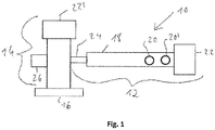
- the ones in the Figure 1 Mixing and kneading machine 10 according to the present invention, shown as a schematic top view, comprises a feed and mixing device 12, a discharge device 14 and an underwater granulation device 16.
- the feed and mixing device 12 comprises a housing 18, on the upper side of which a top feeder 20 and a Filling funnel 20 'for supplying the starting materials to be mixed and kneaded are arranged.
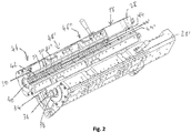
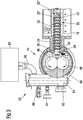
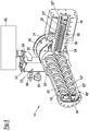
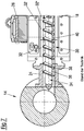
- the entry and mixing device 12 is shown in detail in a perspective view in opened form in FIG Figure 2 and the downstream end of the feeding and mixing device 12 - seen in the conveying direction - is shown in cross section in FIG Figures 3 and 4th shown.
- a drive block 22 is arranged, which comprises a motor and a transmission.
- the housing 18 comprises a connecting element 24 flanged to the downstream end of the housing face.
- a degassing device 26 is provided on the discharge device 14, namely on the side of the discharge device 14 opposite the connection element 24.
- the discharge device 14 also comprises a drive block 22 '. .
- the housing 18 comprises two housing halves 28, 28 ', which are lined on the inside with a so-called housing shell 30, which is composed of a plurality of axially adjacent housing shell parts 32, 32', 32 ".
- the housing shell 30 is referred to in the present patent application as Part of the housing 18.
- the inner circumferential surface of the housing 18 delimits, when the two housing halves 28, 28 'are closed, a cylindrical hollow interior in which a worm shaft 34 is arranged.
- the worm shaft 34 comprises a shaft rod 36, on its circumferential surface wing elements 38
- kneading elements 40 are provided, which are designed as kneading bolts 40.
- Each of these kneading elements is arranged for fixing in a bore provided in the wall of the housing 18, which extends from the inner circumferential surface the housing shell 30 through the wall of the housing 18 extends through.
- each receptacle 42 can have a square cross-section, with each kneading bolt 40 at its lower end having an end that fits precisely into the square-shaped, radially inner end of the receptacles 42 and is therefore non-rotatable in the receptacle 42 when inserted is fixed.
- the kneading bolt 40 is connected at its end lying in the receptacle 42 to a fixing element inserted in the overlying end of the receptacle 42 by screwing.
- the kneading bolts 40 which are equally spaced from one another, in each of the two housing halves 28, 28 ', viewed in the axial direction, are in the form of three rows 44, 44', 44 ".
- the housing 18 is preferably temperature-controllable by means of one or more thermal devices or with electric heating cartridges or heating plates attached to the outside of the housing and is water-cooled or air-cooled, optionally also cooled by another fluid, for example by an oil or another liquid or a special gas.
- the mixing and kneading machine is divided in the axial direction into several process sections 46, 46 ', 46 ", each process section 46, 46', 46" with regard to the number of kneading bolts 40 and the number and extent of the wing elements 38 on the Wave rod 34 is adapted to the function of the individual process sections 46, 46 ', 46 ".
- a degassing device 26 is provided at the downstream end of the housing 18, around the one made in the feeding and mixing device 12 to degas the mixture or melt prior to transfer into the outlet device 14 in order to remove gases and other volatile constituents such as residual moisture and monomers contained therein from the mixture or melt.
- Another disadvantage of this variant is that the mixture for degassing has to be in the form of a melt before it enters the discharge device, namely upstream of the connecting element 24 in the section of the housing 18 in which the degassing device 26 is provided, otherwise none effective degassing is possible.
- This also leads to the fact that the part of the feeding and mixing device 12 located downstream of the degassing device 26 and penetrated by the screw shaft 34 can only be used as a pure conveying section.
- this variant due to the lack of kneading elements 40 in the connecting element 24, complete cleaning of all flanks of the wing elements 38 of the worm shaft 34 is not possible.
- the degassing device 26 is provided on the discharge device 14 and, in addition, kneading elements 40 are also arranged on the inner circumferential surface of the connecting element 24 and extend into the interior of the connecting element 24.
- the degassing therefore no longer takes place in the area of the rapidly rotating and oscillating screw shaft 34 in the feed and mixing device 12, but in the discharge device 14, that is downstream of the rapidly rotating and oscillating screw shaft 34 of the feed and mixing device 12.
- the melt must first be formed further downstream so that the kneading elements 40 can also be arranged on the inner circumferential surface of the connecting element 24 without even thermally sensitive materials of the mixture processed therein, such as PVC, being thermally damaged.
- the length of the feeding and mixing device 12 can be shortened accordingly, whereby both the investment costs and the operating costs of the mixing and kneading machine 10 are considerably reduced.
- deposits on the flanks of the wing elements 38 and at the transition from the wing elements 38 to the shaft rod 36 of the worm shaft 34 also in the connecting element 24 are reliably avoided.
- the discharge device 14 is a counter-rotating twin-screw extruder, that is, one which has two mutually extending and interlocking screws 48, 48 'which rotate in opposite directions when the discharge device 14 is in operation.
- the screws 48, 48 ' have screw flights 50, 50' and shaft rods 52, 52 ', the screws 48, 48' being designed to correspond to one another and arranged in such a way that, when the two screws rotate, between the screw flights 50, 50 'and the shaft bars 52, 52' of the two screws 48, 48 'form chambers moving in the conveying direction.
- the two screws 48, 48 'of the twin screw extruder are not arranged parallel, but rather inclined at an angle of 0.1 to 20 °, preferably 0.5 to 10 ° and particularly preferably 2 to 5 ° are, wherein the two screws 48, 48 'converge in the conveying direction.
- the degassing device 26 of the discharge device 14 comprises a degassing dome 54 which is connected to the housing 56 of the discharge device 14 via an opening (not shown).
- a device 60 comprising a vacuum pump and a separator is arranged on the degassing dome 54 via a hose 58.
- the degassing dome 54 comprises a sight glass 62, a display 64 for negative pressure and a false air valve 66.
- the vacuum pump provided in the device 60 sets the required negative pressure in the degassing dome 54, whereas residual gas or residual liquid is set via the separator provided in the device 60 is withdrawn from the degassing dome 54 and separated.
- the device 60 as in FIG Figure 5 shown as a continuous system or, as in the Figure 6 shown to be designed as a circulatory system.
- the device 60 shown configured as a flow system according to an exemplary embodiment of the present invention, comprises a water ring pump as a vacuum pump 68 and a separator 70, which are connected to one another via a hose line 72.
- the device 60 of this embodiment for fresh water supply comprises a water connection 74, a flow monitor 76, a 2/2 solenoid valve 78 and a throttle valve 80 for setting the amount of water.
- the device 60 shown configured as a circulatory system comprises a Water ring pump as vacuum pump 68 and a separator 70.
- the device 60 of this embodiment comprises a container with heat exchanger 81, a water connection 74 for fresh water supply, a dirt trap 82, a control valve 84, a 2/2 shut-off valve 86, a drain valve 88, and an overflow 90, a check valve 92 and a temperature regulator 94.
- the vacuum pump 68 sucks in the water from the container 81 and conveys the water and any components extracted from the mixture back into the container 81.
- the water in the container 81 is cooled by the heat exchanger.
- the water level in the container 81 is monitored and, if necessary, water is topped up. So that the container 81 cannot be overfilled, the pressureless overflow 90 is provided.
Landscapes
- Engineering & Computer Science (AREA)
- Mechanical Engineering (AREA)
- Life Sciences & Earth Sciences (AREA)
- Manufacturing & Machinery (AREA)
- Food Science & Technology (AREA)
- Animal Husbandry (AREA)
- Chemical & Material Sciences (AREA)
- Polymers & Plastics (AREA)
- Processing And Handling Of Plastics And Other Materials For Molding In General (AREA)
- Mixers Of The Rotary Stirring Type (AREA)
Claims (15)
- Machine de mélange et de malaxage (10) destinée à des processus de préparation en continu tels la production de granulés, de profilés extrudés ou de pièces moulées, tels que des granulés polymères, des profilés extrudés polymères ou des pièces moulées polymères, comportant un dispositif d'entrée et de mélange (12) et un dispositif de sortie (14), le dispositif d'entrée et de mélange (12) comprenant un boîtier (18), un arbre à vis (34) et un élément de liaison (24), l'élément de liaison (24) étant disposé sur une face frontale du boîtier (18) et étant également relié au dispositif de sortie (14), un espace intérieur creux étant réalisé à la fois dans le boîtier (18) et dans l'élément de liaison (24) et l'arbre à vis (34) s'étendant au moins par sections à travers l'espace intérieur du boîtier (18) dans la direction axiale et au moins par sections à travers l'espace intérieur de l'élément de liaison (24) dans la direction axiale, et une pluralité d'éléments de malaxage (40) étant prévus dans le boîtier (18), lesquels éléments de malaxage s'étendent dans l'espace intérieur depuis la surface circonférentielle intérieure du boîtier (18), caractérisée en ce que
des éléments de malaxage (40) sont également disposés sur la surface circonférentielle intérieure de l'élément de liaison (24), lesquels éléments de malaxage s'étendent dans l'espace intérieur de l'élément de liaison (24), et le dispositif de sortie (14) présentant un dispositif de dégazage (26). - Machine de mélange et de malaxage (10) selon la revendication 1, caractérisée en ce que le dispositif de sortie (14) est une extrudeuse bi-vis.
- Machine de mélange et de malaxage (10) selon la revendication 2, caractérisée en ce que le dispositif de sortie (14) est une extrudeuse bi-vis contrarotative.
- Machine de mélange et de malaxage (10) selon la revendication 2 ou 3, caractérisée en ce que les deux vis de l'extrudeuse bi-vis, vues dans la direction axiale, ne sont pas disposées de manière parallèle mais de manière inclinée l'une par rapport à l'autre à un angle de 0,1 à 20°, de préférence de 0,5 à 10° et de manière particulièrement préférée de 2 à 5°, les deux vis convergeant préférablement dans la direction de transport.
- Machine de mélange et de malaxage (10) selon l'une des revendications 2 à 4, caractérisée en ce que les vis du dispositif de sortie (14) sont coniques, les vis se rétrécissant dans la direction de transport.
- Machine de mélange et de malaxage (10) selon l'une des revendications 2 à 5, caractérisée en ce que les vis du dispositif de sortie (14) sont vissées dans le plan horizontal, par rapport à l'arbre à vis du dispositif d'entrée et de mélange, de 45° à 135°, de préférence de 60° à 120°, de manière particulièrement préférée de 80° à 100°, de manière tout particulièrement préférée de 85° à 95° et le plus préférablement de 90°, de sorte que l'extrémité de face frontale de l'arbre à vis (34) s'étendant dans l'élément de liaison (24) est orientée vers les surfaces circonférentielles extérieures des vis du dispositif de sortie (14).
- Machine de mélange et de malaxage (10) selon l'une des revendications précédentes, caractérisée en ce que les éléments de malaxage (40) sur la surface circonférentielle intérieure de l'élément de liaison (24) sont disposés en au moins deux rangées (44, 44', 44") s'étendant, dans la direction axiale, sur au moins une section de la surface circonférentielle intérieure de l'élément de liaison (24), la distance entre le premier et le dernier élément de malaxage (40) d'au moins une rangée couvrant au moins 50 %, de préférence au moins 70 %, de manière particulièrement préférée au moins 80 %, de manière tout particulièrement préférée au moins 90 % et le plus préférablement toute la longueur axiale de la surface circonférentielle intérieure de l'élément de liaison (24).
- Machine de mélange et de malaxage (10) selon la revendication 7, caractérisée en ce que les éléments de malaxage (40) sur la surface circonférentielle intérieure du boîtier (18) sont aussi disposés en au moins deux rangées (44, 44', 44") s'étendant, dans la direction axiale, sur au moins une section de la surface circonférentielle intérieure du boîtier (18), les rangées (44, 44', 44") des éléments de malaxage (40) sur la surface circonférentielle intérieure d'au moins l'extrémité aval du boîtier (18) étant préférablement alignées avec les rangées (44, 44', 44") des éléments de malaxage (40) sur la surface circonférentielle intérieure de l'élément de liaison (24), et préférablement 2 à 8, de préférence 2 à 6 et de manière particulièrement préférée 2, 3, 4 ou 6 rangées (44, 44', 44") d'éléments de malaxage (40), s'étendant dans la direction axiale de la surface circonférentielle intérieure de l'élément de liaison (24), étant disposées sur la surface circonférentielle intérieure de l'élément de liaison (24).
- Machine de mélange et de malaxage (10) selon l'une des revendications précédentes, caractérisée en ce que l'arbre à vis (34) s'étend, vu dans la direction axiale depuis la face frontale du boîtier (18) sur laquelle l'élément de liaison (24) est disposé sur le boîtier (18), sur au moins 50 %, de préférence sur au moins 70 %, de manière particulièrement préférée sur au moins 80 %, de manière tout particulièrement préférée sur au moins 90 % et le plus préférablement sur toute la longueur axiale de l'élément de liaison (24).
- Machine de mélange et de malaxage (10) selon l'une des revendications précédentes, caractérisée en ce que l'élément de liaison (24) et au moins la zone du boîtier (18) attenante à l'élément de liaison (24), laquelle zone s'étend sur au moins 20 %, de préférence sur au moins 40 %, de manière particulièrement préférée sur au moins 60 % et le plus préférablement sur toute la longueur axiale du boîtier (18), ne présentent pas de dispositif de dégazage.
- Machine de mélange et de malaxage (10) selon la revendication 10, caractérisée en ce que l'ensemble du dispositif d'entrée et de mélange (12) ne présente pas de dispositif de dégazage.
- Machine de mélange et de malaxage (10) selon l'une des revendications précédentes, caractérisée en ce qu'un dispositif est disposé à l'extrémité de sortie du dispositif de sortie (14), lequel dispositif est choisi dans le groupe constitué des dispositifs de granulation, des filtres, des dispositifs de coupe, des buses à brins, des outils profilés, des buses à plaques et leurs associations, le dispositif de granulation (16) étant préférablement un dispositif de granulation air/eau, un dispositif de granulation sous l'eau ou un dispositif de granulation à brins.
- Machine de mélange et de malaxage (10) selon l'une des revendications précédentes, caractérisée en ce que le dispositif de dégazage (26) présente un système de génération de pression négative ou est relié à un système de génération de pression négative.
- Machine de mélange et de malaxage (10) selon l'une des revendications précédentes, caractérisée en ce que le dispositif de dégazage (26) est conçu de telle sorte qu'il peut établir et conserver dans le dispositif de sortie (14) une pression absolue inférieure à 800 mbar, de préférence inférieure à 600 mbar, de manière particulièrement préférée de 50 à 500 mbar et le plus préférablement de 200 à 400 mbar.
- Utilisation de la machine de mélange et de malaxage selon l'une des revendications précédentes pour la production de granulés, de profilés extrudés ou de pièces moulées, tels que des granulés polymères, des profilés extrudés polymères ou des pièces moulées polymères.
Priority Applications (12)
| Application Number | Priority Date | Filing Date | Title |
|---|---|---|---|
| ES18170447T ES2862979T3 (es) | 2018-05-02 | 2018-05-02 | Máquina mezcladora y amasadora y su uso |
| EP18170447.9A EP3564005B1 (fr) | 2018-05-02 | 2018-05-02 | Machine de mélange et de malaxage, et son utilisation |
| PL18170447T PL3564005T3 (pl) | 2018-05-02 | 2018-05-02 | Maszyna mieszająco-ugniatająca oraz jej zastosowanie |
| KR1020207034338A KR20210010991A (ko) | 2018-05-02 | 2019-04-18 | 혼합 및 반죽 기계 |
| US17/051,736 US20210229336A1 (en) | 2018-05-02 | 2019-04-18 | Mixing and kneading machine |
| PCT/EP2019/060209 WO2019211109A1 (fr) | 2018-05-02 | 2019-04-18 | Machine de mélange et de malaxage |
| JP2020561754A JP7429649B2 (ja) | 2018-05-02 | 2019-04-18 | 混合および混錬機 |
| BR112020021965-7A BR112020021965B1 (pt) | 2018-05-02 | 2019-04-18 | Máquina de mistura e amassamento |
| CN201980029255.1A CN112423953B (zh) | 2018-05-02 | 2019-04-18 | 混合捏合机器 |
| CA3098507A CA3098507A1 (fr) | 2018-05-02 | 2019-04-18 | Machine de melange et de malaxage |
| MX2020011352A MX2020011352A (es) | 2018-05-02 | 2019-04-18 | Maquina mezcladora y amasadora. |
| TW108114780A TW201946690A (zh) | 2018-05-02 | 2019-04-26 | 混合及捏合機 |
Applications Claiming Priority (1)
| Application Number | Priority Date | Filing Date | Title |
|---|---|---|---|
| EP18170447.9A EP3564005B1 (fr) | 2018-05-02 | 2018-05-02 | Machine de mélange et de malaxage, et son utilisation |
Publications (2)
| Publication Number | Publication Date |
|---|---|
| EP3564005A1 EP3564005A1 (fr) | 2019-11-06 |
| EP3564005B1 true EP3564005B1 (fr) | 2021-01-13 |
Family
ID=62116241
Family Applications (1)
| Application Number | Title | Priority Date | Filing Date |
|---|---|---|---|
| EP18170447.9A Active EP3564005B1 (fr) | 2018-05-02 | 2018-05-02 | Machine de mélange et de malaxage, et son utilisation |
Country Status (12)
| Country | Link |
|---|---|
| US (1) | US20210229336A1 (fr) |
| EP (1) | EP3564005B1 (fr) |
| JP (1) | JP7429649B2 (fr) |
| KR (1) | KR20210010991A (fr) |
| CN (1) | CN112423953B (fr) |
| BR (1) | BR112020021965B1 (fr) |
| CA (1) | CA3098507A1 (fr) |
| ES (1) | ES2862979T3 (fr) |
| MX (1) | MX2020011352A (fr) |
| PL (1) | PL3564005T3 (fr) |
| TW (1) | TW201946690A (fr) |
| WO (1) | WO2019211109A1 (fr) |
Families Citing this family (3)
| Publication number | Priority date | Publication date | Assignee | Title |
|---|---|---|---|---|
| EP3473396B1 (fr) * | 2017-10-17 | 2021-06-16 | Buss AG | Arbre de vis sans fin asymétrique, à deux ailettes, pour une machine de mélange et de malaxage |
| CN113290737B (zh) * | 2021-05-19 | 2023-07-07 | 上海鑫亮塑胶制品股份有限公司 | 一种塑料颗粒加工用双螺杆造粒机及塑料颗粒加工工艺 |
| CN117400436B (zh) * | 2023-12-13 | 2024-02-20 | 四川金元管业有限公司 | 一种高分子管材加工进料设备及进料方法 |
Family Cites Families (31)
| Publication number | Priority date | Publication date | Assignee | Title |
|---|---|---|---|---|
| CH278575A (de) | 1949-11-04 | 1951-10-31 | List Heinz | Misch- und Knetmaschine. |
| US3023455A (en) * | 1959-03-09 | 1962-03-06 | Herbert F Geier | Mixers |
| US3362044A (en) * | 1965-06-07 | 1968-01-09 | Baker Perkins Inc | Mixing and severing apparatus |
| US3458894A (en) | 1966-09-13 | 1969-08-05 | Baker Perkins Inc | Mixing apparatus |
| CH450696A (de) * | 1967-06-13 | 1968-01-31 | Buss Ag | Misch- und Kneteinrichtung |
| DE2120601B2 (de) * | 1971-04-27 | 1973-08-09 | Barmag Barmer Maschinenfabrik Ag, 5600 Wuppertal | Verfahren und vorrichtung zum verarbeiten und entgasen thermisch empfindlicher pulverfoermiger thermoplaste |
| US4127372A (en) * | 1974-05-03 | 1978-11-28 | Colgate-Palmolive Company | Apparatus for manufacturing marbled and striped soap |
| DE2543328B2 (de) * | 1975-09-29 | 1978-01-12 | Paul Troester Maschinenfabrik, 3000 Hannover | Vorrichtung zum extrudieren von thermoplastischen kunststoffen und elastomeren |
| DE2924317C2 (de) * | 1979-06-15 | 1984-07-19 | Hermann Berstorff Maschinenbau Gmbh, 3000 Hannover | Zweistufige Strangpreßvorrichtung für thermoplastische Formmassen, insbesondere für pulverförmige Kunststoffe |
| DE3036397A1 (de) * | 1980-09-26 | 1982-05-13 | Hermann Berstorff Maschinenbau Gmbh, 3000 Hannover | Einrichtung zum aufbereiten von pulverfoermigen kautschukmischungen |
| DE3150719A1 (de) * | 1981-12-22 | 1983-06-30 | Uniroyal Englebert Reifen GmbH, 5100 Aachen | Schneckenextruder |
| DE3242239A1 (de) * | 1982-11-15 | 1984-05-17 | Hermann Berstorff Maschinenbau Gmbh, 3000 Hannover | Einrichtung zur fuellstandsueberwachung eines an einer vacuumquelle angeschlossenen entgasungsdomes fuer extruder |
| US4746478A (en) * | 1985-07-24 | 1988-05-24 | Sekisui Kaseihin Kogyo Kabushiki Kaisha | Method and apparatus for production of foamed thermoplastic material |
| JPS6256114A (ja) * | 1985-09-05 | 1987-03-11 | Sekisui Plastics Co Ltd | 熱可塑性樹脂発泡体の製造装置 |
| JPS6223725A (ja) * | 1985-07-24 | 1987-01-31 | Sekisui Plastics Co Ltd | 熱可塑性樹脂発泡体の製造装置 |
| US4764020A (en) * | 1986-12-12 | 1988-08-16 | Masao Moriyama | Apparatus for mixing and extruding viscous liquids |
| JP2986907B2 (ja) * | 1990-11-29 | 1999-12-06 | 中田造機株式会社 | 押出し機用のピン折れ検出装置 |
| US5200204A (en) * | 1991-03-11 | 1993-04-06 | Permian Research Corporation | Rotary extruder with integral auger feed assembly |
| US5378415A (en) * | 1991-04-07 | 1995-01-03 | Paul Troester Maschinenfabrik | Process for the production of homogeneous rubber blanks |
| IT1250016B (it) * | 1991-09-11 | 1995-03-30 | Renato Fornasero | Perfezionamento nei dispositivi per il recupero di scarti eterogenei, particolarmente scarti eterogenei di materie plastiche. |
| US5213737A (en) * | 1991-12-02 | 1993-05-25 | Corning Incorporated | Extrusion method and apparatus for producing a body from powder material |
| DE4209179C1 (fr) * | 1992-03-20 | 1993-01-14 | Paul Troester Maschinenfabrik, 3000 Hannover, De | |
| GB9210720D0 (en) * | 1992-05-20 | 1992-07-08 | Holyroyd Associates Limited | Production of feedstock for compounding of polymeric materials |
| JP3504014B2 (ja) * | 1995-03-24 | 2004-03-08 | 東芝機械株式会社 | 固体樹脂材料の脱揮用押出し方法および装置 |
| JP3389797B2 (ja) * | 1996-11-07 | 2003-03-24 | 信越化学工業株式会社 | 高疲労耐久性液状シリコーンゴム組成物の製造方法 |
| JP4063412B2 (ja) * | 1998-07-31 | 2008-03-19 | 東洋ゴム工業株式会社 | ゴムの連続混練押出し装置 |
| US6652257B2 (en) * | 1999-02-26 | 2003-11-25 | Denso Corporation | Apparatus for producing ceramic moldings |
| JP3868757B2 (ja) * | 2001-04-25 | 2007-01-17 | 株式会社神戸製鋼所 | ゴム系組成物の混練装置および混練方法 |
| FR2910662B1 (fr) * | 2006-12-26 | 2012-11-02 | Michelin Soc Tech | Procede pour selectionner une configuration optimisee de pneumatiques pour un vehicule terrestre tel qu'une voiture ou une moto de competition |
| JP4928315B2 (ja) * | 2007-03-16 | 2012-05-09 | 住友ゴム工業株式会社 | 連続混合装置 |
| AT510263B1 (de) * | 2010-10-18 | 2012-03-15 | Schulz Helmuth Ing | Vorrichtung zum extrudieren von thermoplastischem kunststoffmaterial |
-
2018
- 2018-05-02 ES ES18170447T patent/ES2862979T3/es active Active
- 2018-05-02 EP EP18170447.9A patent/EP3564005B1/fr active Active
- 2018-05-02 PL PL18170447T patent/PL3564005T3/pl unknown
-
2019
- 2019-04-18 BR BR112020021965-7A patent/BR112020021965B1/pt active IP Right Grant
- 2019-04-18 US US17/051,736 patent/US20210229336A1/en active Pending
- 2019-04-18 WO PCT/EP2019/060209 patent/WO2019211109A1/fr active Application Filing
- 2019-04-18 JP JP2020561754A patent/JP7429649B2/ja active Active
- 2019-04-18 CA CA3098507A patent/CA3098507A1/fr active Pending
- 2019-04-18 CN CN201980029255.1A patent/CN112423953B/zh active Active
- 2019-04-18 MX MX2020011352A patent/MX2020011352A/es unknown
- 2019-04-18 KR KR1020207034338A patent/KR20210010991A/ko not_active Application Discontinuation
- 2019-04-26 TW TW108114780A patent/TW201946690A/zh unknown
Non-Patent Citations (1)
| Title |
|---|
| None * |
Also Published As
| Publication number | Publication date |
|---|---|
| JP2021522090A (ja) | 2021-08-30 |
| CA3098507A1 (fr) | 2019-11-07 |
| US20210229336A1 (en) | 2021-07-29 |
| TW201946690A (zh) | 2019-12-16 |
| CN112423953B (zh) | 2022-11-18 |
| MX2020011352A (es) | 2020-11-24 |
| CN112423953A (zh) | 2021-02-26 |
| PL3564005T3 (pl) | 2021-07-05 |
| BR112020021965B1 (pt) | 2024-03-12 |
| KR20210010991A (ko) | 2021-01-29 |
| EP3564005A1 (fr) | 2019-11-06 |
| JP7429649B2 (ja) | 2024-02-08 |
| BR112020021965A2 (pt) | 2021-01-26 |
| ES2862979T3 (es) | 2021-10-08 |
| WO2019211109A1 (fr) | 2019-11-07 |
Similar Documents
| Publication | Publication Date | Title |
|---|---|---|
| EP3257644B1 (fr) | Procédé d'amorçage pour la dévulcanisation de caoutchouc usagé | |
| DE102004034039B4 (de) | Extrusionsverfahren und Extruder für zellulosehaltiges Material | |
| DE2307717C3 (de) | Kontinuierlich arbeitende Mischvorrichtung für plastische Massen | |
| DE112015002157T5 (de) | Knetvorrichtung und Knetverfahren | |
| EP3564005B1 (fr) | Machine de mélange et de malaxage, et son utilisation | |
| AT413512B (de) | Vorrichtung zur aufbereitung von kunststoffmaterial zu recyclingzwecken | |
| EP0560033B1 (fr) | Procédé et dispositif pour la production des polymères de polycondensat | |
| WO2002030652A1 (fr) | Extrudeuse a plusieurs vis et procede de preparation et / ou de traitement d'elastomeres a matiere de charge ajoutee | |
| DE112015002161T5 (de) | Extruderschnecke, Extruder und Extrusionsverfahren | |
| EP3473395B1 (fr) | Arbre de vis sans fin asymétrique, à trois ailettes, pour une machine de mélange et de malaxage | |
| DE4126390A1 (de) | Misch- und aufbereitungsvorrichtung mit austragspumpe | |
| AT503334B1 (de) | Verfahren und vorrichtung zur plastifizierung von kunststoffmaterial | |
| EP2272651A1 (fr) | Machine à vis sans fin avec élément de malaxage dispersif | |
| AT511564B1 (de) | Mischvorrichtung und verfahren zum mischen eines schüttgutes oder einer pastösen masse | |
| EP4015177B1 (fr) | Machine à vis de chargement permettant de charger une machine à vis de traitement, et procédé associé | |
| DE10149163A1 (de) | Kontinuierliche Herstellung von Elastomermischungen für die Gummiherstellung | |
| EP3656523B1 (fr) | Mélangeur-malaxeur à ventilation efficace dans la zone d'alimentation, et procédé associé | |
| DE102006063021B3 (de) | Planetwalzenextruder | |
| EP0182014A1 (fr) | Procédé pour la préparation de matériaux d'électrodes et dispositif pour la mise en oeuvre de ce procédé | |
| DE102009014589A1 (de) | Extrusionsvorrichtung zur Verarbeitung und/oder Aufbereitung von Zusammensetzungen | |
| RU2778433C2 (ru) | Смешивающе-месильная машина | |
| EP2105201A1 (fr) | Procédé et dispositif de mélange de milieux visqueux ou plastiques | |
| EP4063091A1 (fr) | Dispositif et procédé de traitement thermique des fusions en matière thermoplastique | |
| AT516905B1 (de) | Vorrichtung zum Entgasen von thermoplastischem Kunststoff | |
| WO2023180496A1 (fr) | Agencement d'agglomérateur avec raccordement à une extrudeuse |
Legal Events
| Date | Code | Title | Description |
|---|---|---|---|
| PUAI | Public reference made under article 153(3) epc to a published international application that has entered the european phase |
Free format text: ORIGINAL CODE: 0009012 |
|
| STAA | Information on the status of an ep patent application or granted ep patent |
Free format text: STATUS: THE APPLICATION HAS BEEN PUBLISHED |
|
| AK | Designated contracting states |
Kind code of ref document: A1 Designated state(s): AL AT BE BG CH CY CZ DE DK EE ES FI FR GB GR HR HU IE IS IT LI LT LU LV MC MK MT NL NO PL PT RO RS SE SI SK SM TR |
|
| AX | Request for extension of the european patent |
Extension state: BA ME |
|
| STAA | Information on the status of an ep patent application or granted ep patent |
Free format text: STATUS: REQUEST FOR EXAMINATION WAS MADE |
|
| 17P | Request for examination filed |
Effective date: 20200504 |
|
| RBV | Designated contracting states (corrected) |
Designated state(s): AL AT BE BG CH CY CZ DE DK EE ES FI FR GB GR HR HU IE IS IT LI LT LU LV MC MK MT NL NO PL PT RO RS SE SI SK SM TR |
|
| REG | Reference to a national code |
Ref country code: DE Ref legal event code: R079 Ref document number: 502018003627 Country of ref document: DE Free format text: PREVIOUS MAIN CLASS: B29C0047660000 Ipc: B29C0048685000 |
|
| GRAP | Despatch of communication of intention to grant a patent |
Free format text: ORIGINAL CODE: EPIDOSNIGR1 |
|
| STAA | Information on the status of an ep patent application or granted ep patent |
Free format text: STATUS: GRANT OF PATENT IS INTENDED |
|
| RIC1 | Information provided on ipc code assigned before grant |
Ipc: B29C 48/76 20190101ALI20200826BHEP Ipc: B29C 48/41 20190101ALN20200826BHEP Ipc: B29B 7/42 20060101ALI20200826BHEP Ipc: B29C 48/00 20190101ALN20200826BHEP Ipc: B29B 7/60 20060101ALI20200826BHEP Ipc: B29C 48/38 20190101ALN20200826BHEP Ipc: B29C 48/05 20190101ALN20200826BHEP Ipc: B29C 48/04 20190101ALN20200826BHEP Ipc: B29C 48/685 20190101AFI20200826BHEP Ipc: B29C 48/12 20190101ALN20200826BHEP Ipc: B29B 9/06 20060101ALN20200826BHEP Ipc: B29B 7/74 20060101ALI20200826BHEP Ipc: B29B 7/84 20060101ALI20200826BHEP Ipc: B29B 7/48 20060101ALI20200826BHEP |
|
| INTG | Intention to grant announced |
Effective date: 20200915 |
|
| GRAS | Grant fee paid |
Free format text: ORIGINAL CODE: EPIDOSNIGR3 |
|
| GRAA | (expected) grant |
Free format text: ORIGINAL CODE: 0009210 |
|
| STAA | Information on the status of an ep patent application or granted ep patent |
Free format text: STATUS: THE PATENT HAS BEEN GRANTED |
|
| AK | Designated contracting states |
Kind code of ref document: B1 Designated state(s): AL AT BE BG CH CY CZ DE DK EE ES FI FR GB GR HR HU IE IS IT LI LT LU LV MC MK MT NL NO PL PT RO RS SE SI SK SM TR |
|
| REG | Reference to a national code |
Ref country code: GB Ref legal event code: FG4D Free format text: NOT ENGLISH |
|
| REG | Reference to a national code |
Ref country code: CH Ref legal event code: EP |
|
| REG | Reference to a national code |
Ref country code: IE Ref legal event code: FG4D Free format text: LANGUAGE OF EP DOCUMENT: GERMAN |
|
| REG | Reference to a national code |
Ref country code: DE Ref legal event code: R096 Ref document number: 502018003627 Country of ref document: DE |
|
| REG | Reference to a national code |
Ref country code: AT Ref legal event code: REF Ref document number: 1354230 Country of ref document: AT Kind code of ref document: T Effective date: 20210215 |
|
| REG | Reference to a national code |
Ref country code: CH Ref legal event code: NV Representative=s name: DENNEMEYER AG, CH |
|
| REG | Reference to a national code |
Ref country code: NL Ref legal event code: FP |
|
| REG | Reference to a national code |
Ref country code: LT Ref legal event code: MG9D |
|
| PG25 | Lapsed in a contracting state [announced via postgrant information from national office to epo] |
Ref country code: GR Free format text: LAPSE BECAUSE OF FAILURE TO SUBMIT A TRANSLATION OF THE DESCRIPTION OR TO PAY THE FEE WITHIN THE PRESCRIBED TIME-LIMIT Effective date: 20210414 Ref country code: HR Free format text: LAPSE BECAUSE OF FAILURE TO SUBMIT A TRANSLATION OF THE DESCRIPTION OR TO PAY THE FEE WITHIN THE PRESCRIBED TIME-LIMIT Effective date: 20210113 Ref country code: FI Free format text: LAPSE BECAUSE OF FAILURE TO SUBMIT A TRANSLATION OF THE DESCRIPTION OR TO PAY THE FEE WITHIN THE PRESCRIBED TIME-LIMIT Effective date: 20210113 Ref country code: BG Free format text: LAPSE BECAUSE OF FAILURE TO SUBMIT A TRANSLATION OF THE DESCRIPTION OR TO PAY THE FEE WITHIN THE PRESCRIBED TIME-LIMIT Effective date: 20210413 Ref country code: LT Free format text: LAPSE BECAUSE OF FAILURE TO SUBMIT A TRANSLATION OF THE DESCRIPTION OR TO PAY THE FEE WITHIN THE PRESCRIBED TIME-LIMIT Effective date: 20210113 Ref country code: NO Free format text: LAPSE BECAUSE OF FAILURE TO SUBMIT A TRANSLATION OF THE DESCRIPTION OR TO PAY THE FEE WITHIN THE PRESCRIBED TIME-LIMIT Effective date: 20210413 Ref country code: PT Free format text: LAPSE BECAUSE OF FAILURE TO SUBMIT A TRANSLATION OF THE DESCRIPTION OR TO PAY THE FEE WITHIN THE PRESCRIBED TIME-LIMIT Effective date: 20210513 |
|
| PG25 | Lapsed in a contracting state [announced via postgrant information from national office to epo] |
Ref country code: LV Free format text: LAPSE BECAUSE OF FAILURE TO SUBMIT A TRANSLATION OF THE DESCRIPTION OR TO PAY THE FEE WITHIN THE PRESCRIBED TIME-LIMIT Effective date: 20210113 Ref country code: RS Free format text: LAPSE BECAUSE OF FAILURE TO SUBMIT A TRANSLATION OF THE DESCRIPTION OR TO PAY THE FEE WITHIN THE PRESCRIBED TIME-LIMIT Effective date: 20210113 Ref country code: SE Free format text: LAPSE BECAUSE OF FAILURE TO SUBMIT A TRANSLATION OF THE DESCRIPTION OR TO PAY THE FEE WITHIN THE PRESCRIBED TIME-LIMIT Effective date: 20210113 |
|
| PG25 | Lapsed in a contracting state [announced via postgrant information from national office to epo] |
Ref country code: IS Free format text: LAPSE BECAUSE OF FAILURE TO SUBMIT A TRANSLATION OF THE DESCRIPTION OR TO PAY THE FEE WITHIN THE PRESCRIBED TIME-LIMIT Effective date: 20210513 |
|
| REG | Reference to a national code |
Ref country code: ES Ref legal event code: FG2A Ref document number: 2862979 Country of ref document: ES Kind code of ref document: T3 Effective date: 20211008 |
|
| REG | Reference to a national code |
Ref country code: DE Ref legal event code: R097 Ref document number: 502018003627 Country of ref document: DE |
|
| PG25 | Lapsed in a contracting state [announced via postgrant information from national office to epo] |
Ref country code: SM Free format text: LAPSE BECAUSE OF FAILURE TO SUBMIT A TRANSLATION OF THE DESCRIPTION OR TO PAY THE FEE WITHIN THE PRESCRIBED TIME-LIMIT Effective date: 20210113 Ref country code: EE Free format text: LAPSE BECAUSE OF FAILURE TO SUBMIT A TRANSLATION OF THE DESCRIPTION OR TO PAY THE FEE WITHIN THE PRESCRIBED TIME-LIMIT Effective date: 20210113 |
|
| PLBE | No opposition filed within time limit |
Free format text: ORIGINAL CODE: 0009261 |
|
| STAA | Information on the status of an ep patent application or granted ep patent |
Free format text: STATUS: NO OPPOSITION FILED WITHIN TIME LIMIT |
|
| PG25 | Lapsed in a contracting state [announced via postgrant information from national office to epo] |
Ref country code: DK Free format text: LAPSE BECAUSE OF FAILURE TO SUBMIT A TRANSLATION OF THE DESCRIPTION OR TO PAY THE FEE WITHIN THE PRESCRIBED TIME-LIMIT Effective date: 20210113 Ref country code: SK Free format text: LAPSE BECAUSE OF FAILURE TO SUBMIT A TRANSLATION OF THE DESCRIPTION OR TO PAY THE FEE WITHIN THE PRESCRIBED TIME-LIMIT Effective date: 20210113 Ref country code: RO Free format text: LAPSE BECAUSE OF FAILURE TO SUBMIT A TRANSLATION OF THE DESCRIPTION OR TO PAY THE FEE WITHIN THE PRESCRIBED TIME-LIMIT Effective date: 20210113 |
|
| 26N | No opposition filed |
Effective date: 20211014 |
|
| PG25 | Lapsed in a contracting state [announced via postgrant information from national office to epo] |
Ref country code: LU Free format text: LAPSE BECAUSE OF NON-PAYMENT OF DUE FEES Effective date: 20210502 Ref country code: MC Free format text: LAPSE BECAUSE OF FAILURE TO SUBMIT A TRANSLATION OF THE DESCRIPTION OR TO PAY THE FEE WITHIN THE PRESCRIBED TIME-LIMIT Effective date: 20210113 Ref country code: AL Free format text: LAPSE BECAUSE OF FAILURE TO SUBMIT A TRANSLATION OF THE DESCRIPTION OR TO PAY THE FEE WITHIN THE PRESCRIBED TIME-LIMIT Effective date: 20210113 |
|
| PG25 | Lapsed in a contracting state [announced via postgrant information from national office to epo] |
Ref country code: SI Free format text: LAPSE BECAUSE OF FAILURE TO SUBMIT A TRANSLATION OF THE DESCRIPTION OR TO PAY THE FEE WITHIN THE PRESCRIBED TIME-LIMIT Effective date: 20210113 |
|
| PG25 | Lapsed in a contracting state [announced via postgrant information from national office to epo] |
Ref country code: IE Free format text: LAPSE BECAUSE OF NON-PAYMENT OF DUE FEES Effective date: 20210502 |
|
| PG25 | Lapsed in a contracting state [announced via postgrant information from national office to epo] |
Ref country code: IS Free format text: LAPSE BECAUSE OF FAILURE TO SUBMIT A TRANSLATION OF THE DESCRIPTION OR TO PAY THE FEE WITHIN THE PRESCRIBED TIME-LIMIT Effective date: 20210513 |
|
| PG25 | Lapsed in a contracting state [announced via postgrant information from national office to epo] |
Ref country code: CY Free format text: LAPSE BECAUSE OF FAILURE TO SUBMIT A TRANSLATION OF THE DESCRIPTION OR TO PAY THE FEE WITHIN THE PRESCRIBED TIME-LIMIT Effective date: 20210113 |
|
| P01 | Opt-out of the competence of the unified patent court (upc) registered |
Effective date: 20230608 |
|
| PG25 | Lapsed in a contracting state [announced via postgrant information from national office to epo] |
Ref country code: HU Free format text: LAPSE BECAUSE OF FAILURE TO SUBMIT A TRANSLATION OF THE DESCRIPTION OR TO PAY THE FEE WITHIN THE PRESCRIBED TIME-LIMIT; INVALID AB INITIO Effective date: 20180502 |
|
| PGFP | Annual fee paid to national office [announced via postgrant information from national office to epo] |
Ref country code: NL Payment date: 20230519 Year of fee payment: 6 Ref country code: IT Payment date: 20230526 Year of fee payment: 6 Ref country code: FR Payment date: 20230526 Year of fee payment: 6 Ref country code: DE Payment date: 20230519 Year of fee payment: 6 Ref country code: CZ Payment date: 20230425 Year of fee payment: 6 Ref country code: CH Payment date: 20230605 Year of fee payment: 6 |
|
| PGFP | Annual fee paid to national office [announced via postgrant information from national office to epo] |
Ref country code: TR Payment date: 20230428 Year of fee payment: 6 Ref country code: PL Payment date: 20230424 Year of fee payment: 6 |
|
| PGFP | Annual fee paid to national office [announced via postgrant information from national office to epo] |
Ref country code: BE Payment date: 20230519 Year of fee payment: 6 |
|
| PGFP | Annual fee paid to national office [announced via postgrant information from national office to epo] |
Ref country code: GB Payment date: 20230524 Year of fee payment: 6 Ref country code: ES Payment date: 20230727 Year of fee payment: 6 |
|
| PG25 | Lapsed in a contracting state [announced via postgrant information from national office to epo] |
Ref country code: MK Free format text: LAPSE BECAUSE OF FAILURE TO SUBMIT A TRANSLATION OF THE DESCRIPTION OR TO PAY THE FEE WITHIN THE PRESCRIBED TIME-LIMIT Effective date: 20210113 |