EP3656523B1 - Mixing and kneading machine with efficient venting in the area of the feed-in, and related method - Google Patents
Mixing and kneading machine with efficient venting in the area of the feed-in, and related method Download PDFInfo
- Publication number
- EP3656523B1 EP3656523B1 EP18207797.4A EP18207797A EP3656523B1 EP 3656523 B1 EP3656523 B1 EP 3656523B1 EP 18207797 A EP18207797 A EP 18207797A EP 3656523 B1 EP3656523 B1 EP 3656523B1
- Authority
- EP
- European Patent Office
- Prior art keywords
- housing
- filling device
- mixing
- kneading machine
- extends
- Prior art date
- Legal status (The legal status is an assumption and is not a legal conclusion. Google has not performed a legal analysis and makes no representation as to the accuracy of the status listed.)
- Active
Links
- 238000004898 kneading Methods 0.000 title claims description 133
- 238000000034 method Methods 0.000 title claims description 28
- 238000013022 venting Methods 0.000 title description 2
- 238000011144 upstream manufacturing Methods 0.000 claims description 53
- 239000007858 starting material Substances 0.000 claims description 36
- 238000005192 partition Methods 0.000 claims description 29
- 230000002093 peripheral effect Effects 0.000 claims description 10
- 239000008187 granular material Substances 0.000 claims description 9
- 239000004033 plastic Substances 0.000 claims description 7
- 229920003023 plastic Polymers 0.000 claims description 7
- 239000002184 metal Substances 0.000 claims description 6
- 238000002360 preparation method Methods 0.000 claims description 5
- 238000012856 packing Methods 0.000 claims description 3
- 238000009423 ventilation Methods 0.000 description 11
- 239000012530 fluid Substances 0.000 description 10
- 230000004888 barrier function Effects 0.000 description 9
- 239000000463 material Substances 0.000 description 8
- 239000002245 particle Substances 0.000 description 7
- 239000011236 particulate material Substances 0.000 description 6
- 239000000843 powder Substances 0.000 description 6
- 238000007789 sealing Methods 0.000 description 6
- 230000000149 penetrating effect Effects 0.000 description 5
- IJGRMHOSHXDMSA-UHFFFAOYSA-N Atomic nitrogen Chemical compound N#N IJGRMHOSHXDMSA-UHFFFAOYSA-N 0.000 description 4
- 238000011161 development Methods 0.000 description 4
- 239000007789 gas Substances 0.000 description 4
- 229920000642 polymer Polymers 0.000 description 4
- 238000012545 processing Methods 0.000 description 3
- 239000003570 air Substances 0.000 description 2
- 239000000945 filler Substances 0.000 description 2
- 239000007788 liquid Substances 0.000 description 2
- 239000000155 melt Substances 0.000 description 2
- 239000000203 mixture Substances 0.000 description 2
- 210000003739 neck Anatomy 0.000 description 2
- 229910052757 nitrogen Inorganic materials 0.000 description 2
- 230000003534 oscillatory effect Effects 0.000 description 2
- 230000035515 penetration Effects 0.000 description 2
- 238000005520 cutting process Methods 0.000 description 1
- 230000000694 effects Effects 0.000 description 1
- 239000010419 fine particle Substances 0.000 description 1
- 235000013305 food Nutrition 0.000 description 1
- 238000005469 granulation Methods 0.000 description 1
- 230000003179 granulation Effects 0.000 description 1
- 238000004519 manufacturing process Methods 0.000 description 1
- 238000003801 milling Methods 0.000 description 1
- 235000011837 pasties Nutrition 0.000 description 1
- 239000012779 reinforcing material Substances 0.000 description 1
- 239000007787 solid Substances 0.000 description 1
- 239000000126 substance Substances 0.000 description 1
- 238000012546 transfer Methods 0.000 description 1
- 238000013519 translation Methods 0.000 description 1
- 230000032258 transport Effects 0.000 description 1
- XLYOFNOQVPJJNP-UHFFFAOYSA-N water Substances O XLYOFNOQVPJJNP-UHFFFAOYSA-N 0.000 description 1
Images


Classifications
-
- B—PERFORMING OPERATIONS; TRANSPORTING
- B29—WORKING OF PLASTICS; WORKING OF SUBSTANCES IN A PLASTIC STATE IN GENERAL
- B29C—SHAPING OR JOINING OF PLASTICS; SHAPING OF MATERIAL IN A PLASTIC STATE, NOT OTHERWISE PROVIDED FOR; AFTER-TREATMENT OF THE SHAPED PRODUCTS, e.g. REPAIRING
- B29C48/00—Extrusion moulding, i.e. expressing the moulding material through a die or nozzle which imparts the desired form; Apparatus therefor
- B29C48/25—Component parts, details or accessories; Auxiliary operations
- B29C48/36—Means for plasticising or homogenising the moulding material or forcing it through the nozzle or die
- B29C48/50—Details of extruders
- B29C48/501—Extruder feed section
-
- B—PERFORMING OPERATIONS; TRANSPORTING
- B29—WORKING OF PLASTICS; WORKING OF SUBSTANCES IN A PLASTIC STATE IN GENERAL
- B29B—PREPARATION OR PRETREATMENT OF THE MATERIAL TO BE SHAPED; MAKING GRANULES OR PREFORMS; RECOVERY OF PLASTICS OR OTHER CONSTITUENTS OF WASTE MATERIAL CONTAINING PLASTICS
- B29B7/00—Mixing; Kneading
- B29B7/30—Mixing; Kneading continuous, with mechanical mixing or kneading devices
- B29B7/34—Mixing; Kneading continuous, with mechanical mixing or kneading devices with movable mixing or kneading devices
- B29B7/38—Mixing; Kneading continuous, with mechanical mixing or kneading devices with movable mixing or kneading devices rotary
- B29B7/40—Mixing; Kneading continuous, with mechanical mixing or kneading devices with movable mixing or kneading devices rotary with single shaft
- B29B7/42—Mixing; Kneading continuous, with mechanical mixing or kneading devices with movable mixing or kneading devices rotary with single shaft with screw or helix
- B29B7/422—Mixing; Kneading continuous, with mechanical mixing or kneading devices with movable mixing or kneading devices rotary with single shaft with screw or helix with screw sections co-operating, e.g. intermeshing, with elements on the wall of the surrounding casing
- B29B7/423—Mixing; Kneading continuous, with mechanical mixing or kneading devices with movable mixing or kneading devices rotary with single shaft with screw or helix with screw sections co-operating, e.g. intermeshing, with elements on the wall of the surrounding casing and oscillating axially
-
- B—PERFORMING OPERATIONS; TRANSPORTING
- B29—WORKING OF PLASTICS; WORKING OF SUBSTANCES IN A PLASTIC STATE IN GENERAL
- B29B—PREPARATION OR PRETREATMENT OF THE MATERIAL TO BE SHAPED; MAKING GRANULES OR PREFORMS; RECOVERY OF PLASTICS OR OTHER CONSTITUENTS OF WASTE MATERIAL CONTAINING PLASTICS
- B29B7/00—Mixing; Kneading
- B29B7/30—Mixing; Kneading continuous, with mechanical mixing or kneading devices
- B29B7/34—Mixing; Kneading continuous, with mechanical mixing or kneading devices with movable mixing or kneading devices
- B29B7/38—Mixing; Kneading continuous, with mechanical mixing or kneading devices with movable mixing or kneading devices rotary
- B29B7/40—Mixing; Kneading continuous, with mechanical mixing or kneading devices with movable mixing or kneading devices rotary with single shaft
- B29B7/42—Mixing; Kneading continuous, with mechanical mixing or kneading devices with movable mixing or kneading devices rotary with single shaft with screw or helix
- B29B7/428—Parts or accessories, e.g. casings, feeding or discharging means
-
- B—PERFORMING OPERATIONS; TRANSPORTING
- B29—WORKING OF PLASTICS; WORKING OF SUBSTANCES IN A PLASTIC STATE IN GENERAL
- B29B—PREPARATION OR PRETREATMENT OF THE MATERIAL TO BE SHAPED; MAKING GRANULES OR PREFORMS; RECOVERY OF PLASTICS OR OTHER CONSTITUENTS OF WASTE MATERIAL CONTAINING PLASTICS
- B29B7/00—Mixing; Kneading
- B29B7/30—Mixing; Kneading continuous, with mechanical mixing or kneading devices
- B29B7/58—Component parts, details or accessories; Auxiliary operations
- B29B7/60—Component parts, details or accessories; Auxiliary operations for feeding, e.g. end guides for the incoming material
- B29B7/603—Component parts, details or accessories; Auxiliary operations for feeding, e.g. end guides for the incoming material in measured doses, e.g. proportioning of several materials
-
- B—PERFORMING OPERATIONS; TRANSPORTING
- B29—WORKING OF PLASTICS; WORKING OF SUBSTANCES IN A PLASTIC STATE IN GENERAL
- B29C—SHAPING OR JOINING OF PLASTICS; SHAPING OF MATERIAL IN A PLASTIC STATE, NOT OTHERWISE PROVIDED FOR; AFTER-TREATMENT OF THE SHAPED PRODUCTS, e.g. REPAIRING
- B29C48/00—Extrusion moulding, i.e. expressing the moulding material through a die or nozzle which imparts the desired form; Apparatus therefor
- B29C48/25—Component parts, details or accessories; Auxiliary operations
- B29C48/285—Feeding the extrusion material to the extruder
- B29C48/288—Feeding the extrusion material to the extruder in solid form, e.g. powder or granules
-
- B—PERFORMING OPERATIONS; TRANSPORTING
- B29—WORKING OF PLASTICS; WORKING OF SUBSTANCES IN A PLASTIC STATE IN GENERAL
- B29C—SHAPING OR JOINING OF PLASTICS; SHAPING OF MATERIAL IN A PLASTIC STATE, NOT OTHERWISE PROVIDED FOR; AFTER-TREATMENT OF THE SHAPED PRODUCTS, e.g. REPAIRING
- B29C48/00—Extrusion moulding, i.e. expressing the moulding material through a die or nozzle which imparts the desired form; Apparatus therefor
- B29C48/25—Component parts, details or accessories; Auxiliary operations
- B29C48/36—Means for plasticising or homogenising the moulding material or forcing it through the nozzle or die
- B29C48/375—Plasticisers, homogenisers or feeders comprising two or more stages
-
- B—PERFORMING OPERATIONS; TRANSPORTING
- B29—WORKING OF PLASTICS; WORKING OF SUBSTANCES IN A PLASTIC STATE IN GENERAL
- B29C—SHAPING OR JOINING OF PLASTICS; SHAPING OF MATERIAL IN A PLASTIC STATE, NOT OTHERWISE PROVIDED FOR; AFTER-TREATMENT OF THE SHAPED PRODUCTS, e.g. REPAIRING
- B29C48/00—Extrusion moulding, i.e. expressing the moulding material through a die or nozzle which imparts the desired form; Apparatus therefor
- B29C48/25—Component parts, details or accessories; Auxiliary operations
- B29C48/36—Means for plasticising or homogenising the moulding material or forcing it through the nozzle or die
- B29C48/395—Means for plasticising or homogenising the moulding material or forcing it through the nozzle or die using screws surrounded by a cooperating barrel, e.g. single screw extruders
- B29C48/397—Means for plasticising or homogenising the moulding material or forcing it through the nozzle or die using screws surrounded by a cooperating barrel, e.g. single screw extruders using a single screw
-
- B—PERFORMING OPERATIONS; TRANSPORTING
- B29—WORKING OF PLASTICS; WORKING OF SUBSTANCES IN A PLASTIC STATE IN GENERAL
- B29C—SHAPING OR JOINING OF PLASTICS; SHAPING OF MATERIAL IN A PLASTIC STATE, NOT OTHERWISE PROVIDED FOR; AFTER-TREATMENT OF THE SHAPED PRODUCTS, e.g. REPAIRING
- B29C48/00—Extrusion moulding, i.e. expressing the moulding material through a die or nozzle which imparts the desired form; Apparatus therefor
- B29C48/25—Component parts, details or accessories; Auxiliary operations
- B29C48/36—Means for plasticising or homogenising the moulding material or forcing it through the nozzle or die
- B29C48/395—Means for plasticising or homogenising the moulding material or forcing it through the nozzle or die using screws surrounded by a cooperating barrel, e.g. single screw extruders
- B29C48/45—Axially movable screws
-
- B—PERFORMING OPERATIONS; TRANSPORTING
- B29—WORKING OF PLASTICS; WORKING OF SUBSTANCES IN A PLASTIC STATE IN GENERAL
- B29C—SHAPING OR JOINING OF PLASTICS; SHAPING OF MATERIAL IN A PLASTIC STATE, NOT OTHERWISE PROVIDED FOR; AFTER-TREATMENT OF THE SHAPED PRODUCTS, e.g. REPAIRING
- B29C48/00—Extrusion moulding, i.e. expressing the moulding material through a die or nozzle which imparts the desired form; Apparatus therefor
- B29C48/25—Component parts, details or accessories; Auxiliary operations
- B29C48/36—Means for plasticising or homogenising the moulding material or forcing it through the nozzle or die
- B29C48/50—Details of extruders
- B29C48/505—Screws
Definitions
- the present invention relates to a mixing and kneading machine for continuous preparation processes, such as for the production of granules, extruded profiles or molded parts, and a method for mixing and kneading a starting material using such a mixing and kneading machine.
- Mixing and kneading machines of this type are used in particular for the preparation of plastic and / or pasty materials.
- the working element of such a mixing and kneading machine forms a screw shaft arranged therein, which transports or conveys the material to be processed forwards in the axial direction and thereby mixes the components of the material with one another.
- such mixing and kneading machines are used for processing viscoplastic masses, for homogenizing and plasticizing plastics, for incorporating fillers and reinforcing materials, and for producing starting materials for the food industry.
- the starting material or at least one component of the starting material is in the form of a particulate material, such as, for example, a powder or granulate.
- mixing and kneading machines can, for example, be operated in such a way that a melt is first generated from the starting material before the melt thus generated is conveyed through the screw shaft in the axial direction through the mixing and kneading machine and thereby homogenized.
- the temperature set in the mixing and kneading machine can be between 50 ° and 400 ° C., at least in sections.
- Mixing and kneading machines of this type are also particularly suitable for producing polymer granules, extruded polymer profiles, molded polymer parts and the like, if on downstream end of the machine a suitable discharge device, such as a discharge extruder, is arranged and connected to a granulation device or a similar device, such as an intermittent cutting device, strand die, profile tool, plate die or a similar device.
- a suitable discharge device such as a discharge extruder
- a granulation device or a similar device such as an intermittent cutting device, strand die, profile tool, plate die or a similar device.
- Such mixing and kneading machines are, for example, from CH 278 575 A as well as from the CH 464 656 known.
- the worm shaft preferably not only carries out a rotary movement, but at the same time also moves translationally back and forth in the axial direction, ie in the direction of the worm shaft.
- the sequence of movements is therefore preferably characterized in that the worm shaft, viewed in the axial direction, executes an oscillatory movement superimposed on the rotation.
- This sequence of movements enables the introduction of internals, namely kneading elements, such as kneading bolts or kneading teeth, into the housing of the feeding and mixing device.
- the worm arranged on the main shaft does not run continuously - viewed in the cross section of the wave bar - but is divided into a plurality of individual wing elements, each extending over a certain angular section of the cross-sectional circumference of the Extend the wave bar.
- Adjacent wing elements are spaced from one another both in the axial direction and in the outer circumferential direction of the shaft rod, ie a gap is provided between adjacent wing elements both in the axial direction and in the outer circumferential direction of the shaft rod.
- the entire shaft rod of the worm shaft or an axial section of the shaft rod of the worm shaft, based on the cross-sectional circumference, comprises three wing elements, which each extend over an angular section of, for example, 100 ° of the cross-sectional circumference of the shaft rod, one speaks of a three-winged worm shaft or a three-bladed screw shaft section.
- the rotation and the translational movement of the worm shaft in the axial direction are controlled so that the flanks of the individual wing elements come close to the corresponding kneading elements in order to compress the material to be mixed and kneaded and to exert a shear effect on it in order to facilitate the mixing and / or To convey the kneading process without the kneading elements colliding with the wing elements.
- the kneading elements come so close to the flanks of the wing elements that the kneading elements prevent components of the mixture from being deposited on the flanks of the wing elements, so that the kneading elements also cause the wing elements to be cleaned as a result.
- the number and geometry of the wing elements must be adapted to the number of kneading elements.
- a device for gravimetric mixing of several substances which has a mixing screw shaft and a filling funnel, the filling funnel having a vertical partition. This should subdivide the into several compartments so that several different solids can be filled in via the filling funnel.
- the WO 2011/014902 A1 referenced which describes the avoidance of air introduction via the feed hopper.
- a filling funnel is shown which is divided into several compartments by a partition, and polymer particles of various sizes and qualities can be filled through the compartments.
- alternative solutions are described, such as the provision of a screw or a pulse generator.
- a challenge with these mixing and kneading machines is the sealing of the rotating and oscillatory back and forth moving worm shaft to the gear flange connected to it, via which the worm shaft is connected to the gear unit.
- Such a seal is particularly important in order to avoid the escape of particulate material, such as in particular powder and finely divided granulate, from the processing space of the mixing and kneading machine into the gear flange connected to it or even into the gear.
- particulate material is fed in through a hopper, for example, air is automatically introduced into the process space of the mixing and kneading machine, because the bulk density of such particulate material is often 0.5 to 0.7 g / cm 3 and for some starting materials even more is below.
- the object of the present invention is to provide such a mixing and kneading machine, during the operation of which the seal arranged between the support shaft, the housing wall surrounding it and the gear flange, in particular the stuffing box, is relieved, so that its operating time or the period of time , during which this keeps the connection area between the support shaft and the gear flange airtight or reliably prevents air and particulate material from penetrating into the gear flange from the process space of the mixing and kneading machine.
- a mixing and kneading machine for continuous preparation processes, such as for kneading and mixing particulate starting material and / or for producing granules, extruded profiles or molded parts, with a housing in which one of the inner circumferential surface of the housing limited and in the longitudinal direction of the mixing and kneading machine running hollow interior is formed, with a screw shaft extending at least in sections in the axial direction through the interior of the housing, which rotates in operation in the (preferably cylindrical) interior of the housing and at the same time moves translationally back and forth in the axial direction , with a drive which rotates the worm shaft during operation, and with a filling device arranged on the housing for feeding at least one starting material to be mixed and kneaded into the interior of the housing, the filling device extending through a recess extending through the housing wall or is connected to a recess extending through the housing wall, characterized in that the
- this configuration of the filling device it is achieved that by feeding the starting material via one of the cavities of the filling device Air introduced into the process space or interior of the mixing and kneading machine is simply discharged from the mixing and kneading machine again via the other cavity or at least for the most part via the other cavity of the filling device.
- the two cavities of the filling device of the mixing and kneading machine are in their lower area with the inner or process space, ie the space between the screw shaft and the housing inner peripheral surface, the mixing and kneading machine connected. Air entrained by one of the two Cavities are entered into the process space via the recess, for this reason can penetrate into the filling device via the lower opening of the adjacent cavity and escape through this from bottom to top through the filling device into the environment. To improve the escape of air through this cavity of the filling device, a vacuum, for example a vacuum between 50 kPa and just under 100 kPa, can also be applied to this cavity.
- one of the at least two cavities of the filling device functions as a supply or filling channel for the starting material
- another of the at least two cavities of the filling device functions as a ventilation channel. Therefore, the air introduced into the process space when the starting material is fed is removed quickly and reliably, so that it does not collect in the process space, or at least not to a significant extent, and not during the backward stroke which translates in the axial direction of the mixing and kneading machine reciprocating worm shaft can be pressed against the stuffing box. This prevents air and powder or granulate particles entrained in it from getting through the stuffing box into the gearbox flange.
- the screw thread is optimally filled with the starting material, especially in the case of powder with a very low bulk density.
- the seal arranged between the support shaft of the worm shaft, the housing wall surrounding it and the gear flange, in particular the stuffing box, is relieved, so that its operating time or the period of time during which it forms the connection area between the Keeps the support shaft and the gear flange airtight or prevents air and particulate material from penetrating from the process space Mixing and kneading machine in the gear flange reliably prevents, is significantly extended.
- the at least two cavities of the filling device are separated from one another in such a way that at least one of the at least two cavities - viewed in the longitudinal direction of the housing - is offset or at least partially offset from at least one other of the at least two cavities .
- arranged offset means that one cavity is arranged upstream of the other cavity.
- Upstream and downstream means that the upstream cavity is arranged closer to the upstream end of the housing of the mixing and kneading machine than the downstream cavity, and that the downstream cavity is arranged closer to the downstream end of the housing of the mixing and kneading machine than the upstream cavity.
- the upstream end of the housing of the mixing and kneading machine is the end of the housing which is connected to the drive or to which the starting material is supplied, and the downstream end of the housing of the mixing and kneading machine is the end of the housing from which the mixed and kneaded product is discharged.
- Partially offset in this context means that the upstream part of a cavity is arranged upstream of the upstream part of the other cavity, whereas the other parts of the two cavities can be arranged next to one another in relation to the longitudinal direction of the housing.
- the starting material is fed to the process space or interior of the housing of the mixing and kneading machine only through the downstream cavity of the filling device, whereas the upstream cavity of the filling device is left free and can thus function as a venting channel.
- the air introduced into the interior of the housing of the mixing and kneading machine through the feeder through the downstream cavity of the filling device is pushed under the lower opening of the upstream cavity of the filling device during the backward stroke of the screw shaft, so that the air flows through the upstream cavity of can escape from the filling device at the bottom upwards.
- the present invention is not particularly limited as long as at least one of the cavities of the filling device is dimensioned and configured in such a way that the intended amount of starting material can be supplied per unit of time. Good results are obtained in particular when the filling device has the shape of a cuboid, a cylinder, a cone, a truncated cone, an inverted cone, an inverted truncated cone, a wedge, a truncated wedge, an inverted wedge or an inverted truncated wedge.
- the filling device extends through a recess extending through the housing wall or is connected to a recess extending through the housing wall.
- a filling device extending through a recess extending through the housing wall is understood to mean that the lower side walls of the filling device extend along the inner edges of the recess and are connected to them, because otherwise an unacceptable cavity between the lower side walls of the filling device and the Inner edges of the recess would arise.
- a filling device connected to a recess extending through the housing wall is understood to mean that the lower side walls of the Place the filling device flush on the upper boundary of the recess so that the inner edges of the lower side walls of the filling device are connected flush with the inner edges of the recess.
- the filling device is understood to be the sum of the cavities which are defined by the side walls of the filling device and the inner edges of the recess are formed. Accordingly, when the filling device touches down on the recess, the filling device is understood to be the sum of the filling device and the recess.
- An inverted wedge or inverted wedge stump denotes a wedge or wedge stump rotated by 180 ° with respect to the horizontal, ie a wedge or wedge stump in which the larger base surface is arranged at the top.
- the sides of the filling device are closed by walls, the lower end of the filling device is open and the upper end of the filling device is open or is provided with a cover provided with two or more open nozzles.
- the at least one partition extends over the entire height of the filling device.
- the at least one partition it is also possible, albeit less preferred, for the at least one partition to extend over at least 50% or over at least 80% or over at least 90% of the total height of the filling device, preferably from the lower edge of the filling device or the recess the housing wall when the filling device rests on it, and more preferably from just above the outermost limit of the worm shaft, namely from 0.1 to 10 mm, more preferably from 0.3 to 5 mm and very particularly preferably from 0.5 to 2 mm above the outermost limit of the worm shaft at the top.
- the starting material must be introduced carefully into the feed shaft of the filling device.
- the height of the filling device is the vertical distance from the lower edge of the filling device or the recess in the housing wall, when the filling device rests on it, to the upper end of the side walls, ie in the event that a cover is arranged on the upper end of the filling device is understood, up to the lower edge of the cover, regardless of whether other structures, such as filler necks, are present on the cover.
- the filling device has the shape of a cuboid, a truncated wedge or an inverted truncated wedge, a partition being at least substantially parallel to the cross-sectional area of the housing over at least 50%, preferably over at least 80% %, particularly preferably over at least 90% and most preferably over the entire height of the filling device and over at least 50%, preferably over at least 80%, particularly preferably over at least 90% and most preferably over the entire width of the filling device.
- essentially parallel to the cross-sectional area means that the partition wall is at an angle of + 20 ° C to -20 °, preferably + 10 ° C to -10 ° and particularly preferably + 5 ° C to -5 ° the cross-sectional area is arranged. Most preferably, the partition extends parallel to the cross-sectional area of the housing.
- the filling device comprises two partition walls, one partition of which extends at least substantially parallel to the cross-sectional area of the housing and the other partition extends at least substantially parallel to the longitudinal surface of the housing, the two partition walls so with one another are connected, the two completely separate cavities are provided as seen in the cross section of the funnel.
- both partition walls extend over at least 50%, more preferably over at least 80%, particularly preferably over at least 90% and most preferably over the entire height of the filling device.
- a seal preferably a stuffing box, sealing the worm shaft against the inner circumferential surface of the housing is provided and in the housing at least one seal is provided Inner circumferential surface of the housing in sections into the housing (ie in the housing wall) extending into and connected to the upstream end of the filling device relief channel is provided, which extends from the upstream end of the filling device in the longitudinal direction of the housing at least partially in the direction of the seal.
- the seal is necessary in order to prevent air and / or starting material from penetrating into the gearbox flange during a backward stroke of the worm shaft moving axially translationally back and forth.
- at least one relief channel which extends from the upstream end of the filling device in the longitudinal direction of the housing, at least in sections in the direction of the seal, it is achieved that the air with any starting material which may be entrained on a backward stroke of the axially translatory back and forth moving screw shaft is pressed in the upstream direction and is not discharged through the filling device through the upstream cavity of the filling device acting as a ventilation channel, but in an area upstream of the upstream end of the cavity functioning as a ventilation channel Filling device arrives, through which at least one relief channel is fed to the ventilation channel and is thus discharged from the mixing and kneading machine via the filling device.
- a relief channel extending in sections into the housing is understood to mean a recess which extends from the inner circumferential surface of the housing into the housing wall, but not completely through the housing wall.
- the recess can have any geometric shape in plan view, that is, other than rectangular.
- the channel component in the word relief channel is meant here functionally and not related to the geometric shape of the relief channel.
- the relief channel preferably has a rectangular shape in plan view, that is to say, viewed three-dimensionally, the shape of a channel.
- the relief channel preferably extends on the inner circumferential surface of the housing from the upstream inner edge of the recess through which the lower part of the filling device or the lower parts of the side walls of the filling device extend, or with which the lower part of the filling device or the lower parts extend of the side walls of the filling device are connected, at least substantially parallel to the longitudinal direction of the housing in the upstream direction in the direction of the seal or stuffing box.
- essentially parallel to the longitudinal direction of the housing means that the relief channel is at an angle of + 20 ° C to -20 °, preferably + 10 ° C to -10 ° and particularly preferably + 5 ° C to -5 ° is arranged to the longitudinal direction of the housing.
- the extends Relief channel parallel to the longitudinal direction of the housing can also run in the form of a spiral or the like.
- the housing of such a mixing and kneading machine is usually composed of two housing halves which can be folded away from one another or closed to form a closed housing.
- a relief channel is provided on the edge of the inner circumferential surface of one of the two housing halves or in each case a relief channel is provided on the edge of the inner circumferential surface of each of the two housing halves.
- the relief channel or channels can be produced simply by milling a groove on the edge of the housing half wall.
- the at least one relief channel extends from the upstream end of the filling device over at least 20%, preferably at least 40%, more preferably at least 60%, even more preferably at least 80%, particularly preferably at least 90% and at most preferably extends over the entire length up to the seal.
- the at least one relief channel extends into the housing wall by 1 to 50%, preferably by 2 to 20% and particularly preferably by 2 to 10%, as seen from the inner circumferential surface of the housing and / or a width of 0.005 to 0.5 Da, preferably 0.02 to 0.3 Da, particularly preferably 0.05 to 0.2 Da and very particularly preferably 0.08 to 0.12 Da, such as about 0, 1 Da, where Da is the diameter of the hollow interior, and when the hollow interior is not cylindrical, the greatest distance is from a point on the inner peripheral surface to a perpendicularly opposite point on the inner peripheral surface of the housing.
- the width is 0.1 mm to 100 mm, preferably 0.5 mm to 20 mm and more preferably 0.5 mm to 10 mm.
- Such a relief duct has a volume that is large enough for air to be discharged efficiently.
- the present invention is not particularly restricted. Good results are obtained in particular when the at least one relief channel has an oval, round, rectangular or square and preferably a rectangular or square cross section.
- the seal is a stuffing box, in which at least one metal ring or plastic ring made of temperature-resistant plastic is provided between the packing cords, with the longitudinal section of the housing radially surrounding the seal or stuffing box at least one connection channel is provided through which a gas can flow from the upstream region of the housing into the interior of the housing.
- the metal ring or plastic ring can in particular also be designed in two parts so that it can be easily exchanged without the worm shaft having to be removed.
- the seal or stuffing box can be further relieved by inserting a gas acting as a barrier fluid, such as air or nitrogen, or a liquid acting as a barrier fluid, such as water or another product-compatible liquid, via the at least one connection channel the interior of the housing is supplied, preferably with a higher pressure than the pressure applied in the interior.
- the barrier fluid is distributed over the metal ring or plastic ring. This ensures that the Resistance to any penetration of air from the interior of the housing through the seal or stuffing box is increased and thus the stuffing box is relieved even further. In addition, this prevents any material particles entrained by the air from penetrating into the seal or stuffing box in an even more reliable manner.
- the service life of a seal or stuffing box in the mixing and kneading machine is drastically increased, namely, for example, from 2 weeks to over 6 months.
- the barrier fluid that has penetrated the interior reaches the ventilation channel via the relief channel and leaves the mixing and kneading machine via this, so that the introduced barrier fluid does not impair the preparation of the starting material in the mixing and kneading machine.
- a measuring device in each of the embodiments described above which sets and monitors the barrier fluid pressure and preferably generates an alarm if the pressure is too low.
- a pressure measuring device can be used for this purpose.
- the mixing and kneading machine comprises a filling device configured as described above.
- the mixing and kneading machine can, but does not have to, have one or more further filling devices.
- Each of the optional further filling device (s) can be configured like the filling device according to the invention described above. However, each of the optional further filling device (s) is preferably configured differently than the one described above, namely as a side feed to the housing. If the mixing and kneading machine has two or more filling devices, it is preferred that at least the most upstream filling device is designed as described above.
- the one or more filling devices arranged downstream thereof can be provided, for example, in order to add a further component to be mixed to add the interior of the mixing and kneading machine at a point in which the component (s) already added upstream have already been premixed or melted to a certain extent.
- a mixing and kneading machine comprises a housing and a worm shaft arranged in the housing.
- the housing preferably comprises two housing halves which can, but need not be, lined on the inside with a so-called housing shell.
- the housing shell if present, is considered to be part of the housing in the present patent application.
- the inner circumferential surface of the housing delimits a preferably cylindrical hollow interior, that is to say an interior with a circular cross-section.
- the worm shaft comprises a shaft rod or a support shaft, on the circumferential surface of which wing elements are arranged, which extend radially outward on the circumferential surface of the shaft rod, the individual wing elements being spaced from one another.
- receptacles for kneading elements such as kneading bolts, kneading teeth and the like, are provided in the two housing halves.
- Each of the receptacles is a bore which extends from the inner circumferential surface of the housing through the housing wall.
- the receptacles for the kneading bolts which are equally spaced from one another, extend in each of the two housing halves, viewed in the axial direction, preferably in the form of at least two rows and preferably two to six rows.
- the wing elements are also arranged on the circumferential surface of the shaft rod in at least two and preferably two to six rows extending in the axial direction of the worm shaft.
- Another object of the present invention is a method according to claim 14 for mixing and kneading a starting material, which is operated in a mixing and kneading machine described above.
- the inventive method includes Steps of switching on the drive and supplying starting material to be mixed and kneaded via selectively only one of the at least two cavities of the filling device into the interior of the housing.
- the method is preferably carried out in a mixing and kneading machine described above, which comprises at least one relief channel and at least one connecting channel, the gas or barrier fluid being introduced into the housing at a pressure of around 500 Pa to 10 MPa and preferably around 10 KPa to 0.3 MPa is higher than the pressure applied in the interior of the housing.
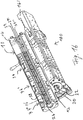
- the mixing and kneading machine shown and designated as a whole by 100 comprises a housing 10 and a worm shaft 12 arranged in the housing 10.
- the housing 10 comprises two housing halves 14, 14 ′, which are lined on the inside with a so-called housing shell 16.
- the housing shell 16 is considered to be part of the housing 10 in the present patent application.
- the inner circumferential surface of the housing 10 delimits a cylindrical hollow interior 18, that is to say an interior 18 with a circular cross-section.
- the worm shaft 12 comprises a shaft rod 20, on the circumferential surface of which wing elements 22 are arranged, which extend radially outward on the circumferential surface of the shaft rod 20, the individual wing elements 22 being spaced from one another.
- receptacles 28 for kneading elements 24, that is for kneading bolts, kneading teeth and the like are provided in the two housing halves 14, 14 '.
- Each of the receptacles 28 is a bore 28 which extends from the inner circumferential surface of the housing shell 16 through the housing wall.
- the lower, radially inner end of each receptacle 28 can, for example, have a square cross-section.
- Each kneading bolt 24 can then, for example, have at its lower end an end that fits precisely into the square, radially inner end of the receptacles 28 and is thereby fixed in the receptacle 28 so that it cannot rotate when it is inserted.
- the kneading bolt 24 is connected at its end lying in the receptacle 28 to a fixing element (not shown) inserted in the overlying end of the receptacle 28 by screwing.
- the kneading bolt 24 can also have an internal thread for a screw and can be fixed with a screw instead of the fixing element and the nut.
- the equally spaced receptacles 28 for the kneading bolts 24 in each of the two housing halves 14, 14 ', viewed in the axial direction, extend in the form of three rows 29, 29', 29 ".
- the total number of rows is of recordings 29, 29 ', 29 "of the housing six.
- a row is understood to mean that a connecting line laid over the receptacles 28 of a row 29, 29', 29" which are spaced apart from one another in the axial direction is a straight line.
- the mixing and kneading machine 100 is divided in the axial direction into several process sections 34, 34 ', 34 ", each process section 34, 34', 34" with regard to the number of kneading bolts 24 and the number and extent of the wing elements 22 the wave bar 20 is adapted to the function of the individual process sections 34, 34 ', 34 ".
- the middle row is also in the middle section 34' of the lower housing half 14 ' equipped with kneading bolts, so that the middle section 34 'of the housing 10 has a total of two rows of opposing kneading bolts 24, ie the angle between the two rows of kneading bolts 24 on the inner circumferential surface of the housing This 10 is 180 °.
- the starting material to be mixed is fed to the mixing and kneading machine 100 via the filling device 36 designed as a filling funnel, then guided through the process sections 34, 34 ', 34 "and finally discharged via the outlet opening 37.
- the mixing and kneading machine 100 can also have more process sections, such as, in particular, four process sections, or fewer process sections, such as two or one process section.
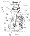
- the mixing and kneading machine 100 is similar to that in FIGS Figures 1a and 1b and further comprises a drive by which the worm shaft 12 is driven or rotated during the operation of the mixing and kneading machine 100.
- a gear is arranged between the drive and the upstream end of the housing and is connected to the upstream end of the housing via a gear flange 38.
- the filling device 36 arranged on the housing 10 for feeding at least one starting material to be mixed and kneaded into the interior 18 of the housing 10 is connected to a recess 42 extending through the housing wall 40.
- the filling device 36 has the shape of an inverted wedge stump.
- the lower end of the side walls 44, 44 'laterally delimiting the filling device 36 are flush with the upper boundary of the recess 42, so that the inner edges of the lower side walls 44, 44' of the filling device 36 are connected flush with the inner edges 46 of the recess 42 are.
- the upper end of the filling device 36 is delimited by a cover 48, the cover 48 comprising two open nozzles 50, 50 '.
- a partition 52 extending over the entire height and width of the filling device 36 is provided in the filling device 36 and separates the filling device into two cavities 54, 54 '.
- the two cavities 54, 54 ' are arranged offset from one another as seen in the longitudinal direction of the housing 10, the cavity 54, seen from the upstream end of the housing 10 facing the drive, downstream of the other (in the Figure 2 rear cavity) is arranged.
- the mixing and kneading machine 100 shown in the figure is continuously introduced into the interior space 18 of the mixing and kneading machine 100 through the downstream cavity 54 of the filling device 36 serving as a filling channel.
- the Air introduced into the interior 18 penetrates largely through the lower opening of the adjacent cavity (in the Figure 2 rear cavity) and is thereby discharged from bottom to top through the filling device 36.
- the air introduced into the interior 18 when the starting material is supplied is removed quickly and reliably, so that it does not accumulate, or at least not to a significant extent, in the interior 18 and not during the backward stroke of the mixing and axial direction Kneading machine 100 translationally reciprocating screw shaft 12 against which the screw shaft 12 sealing seal can be pressed. This prevents air and powder or granulate particles entrained therein from being able to pass through the seal into the gear flange 38.
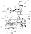
- FIG. 3a a longitudinal section of the housing 10 and the filling device 36 of a mixing and kneading machine 100 according to another embodiment of the present invention is shown.
- the filling device 36 comprises, as in FIG Figure 3b shown in more detail, two partition walls 52, 52 ', of which one partition wall 52 extends parallel to the cross-sectional surface of the housing 10 and the other partition wall 52' extends parallel to the longitudinal surface of the housing 10.
- the two partition walls 52, 52 ' are connected to one another in such a way that, viewed in the cross section of the filling funnel 36, two cavities 54, 54' that are completely separate from one another are provided.
- the filling device 36 is limited by a cover 48 which comprises three nozzles 50, 50 ', 50 ".
- a seal 56 in the form of a stuffing box 56 is provided between the gear flange 38 and the connected upstream end of the housing 10, in order to seal the worm shaft 12 against the inner circumferential surface of the housing 10.
- a relief channel 58 is arranged in the housing 10 or the housing wall 40.
- the relief channel 58 is a section extending from the inner circumferential surface of the housing 10 into the housing wall 40 and with the upstream end of the filling device 36 connected recess which extends from the upstream end of the Filling device 36, viewed in the longitudinal direction of the housing 10, extends in the direction of the stuffing box 56, specifically parallel to the longitudinal direction of the housing 10.
- connection channel 60 is additionally provided, via which a fluid can flow from the upstream region of the housing 10 into the interior 18 of the housing 10.
- the stuffing box 56 has a metal ring 62 between the packing cords.
- a further relief of the seal or stuffing box 56 can be achieved via the connecting channel 60 by supplying a gas acting as a barrier fluid, such as air or nitrogen, via the connecting channel 60 into the interior 18 of the housing 10, preferably at a higher pressure than the pressure present in the interior space 18.
Description
Die vorliegende Erfindung betrifft eine Misch- und Knetmaschine für kontinuierliche Aufbereitungsprozesse, wie zur Herstellung von Granulat, Strangpressprofilen oder Formteilen, sowie ein Verfahren zum Mischen und Kneten eines Ausgangsmaterials unter Verwendung einer solchen Misch- und Knetmaschine.The present invention relates to a mixing and kneading machine for continuous preparation processes, such as for the production of granules, extruded profiles or molded parts, and a method for mixing and kneading a starting material using such a mixing and kneading machine.
Derartige Misch- und Knetmaschinen werden insbesondere zum Aufbereiten von plastischen und/oder pastösen Massen eingesetzt. Das Arbeitsorgan einer derartigen Misch- und Knetmaschine bildet eine darin angeordnete Schneckenwelle, welche das zu verarbeitende Material in axialer Richtung vorwärts transportiert bzw. fördert und dabei die Komponenten des Materials miteinander vermischt. Beispielsweise werden derartige Misch- und Knetmaschinen zum Verarbeiten von zähplastischen Massen, zum Homogenisieren und Plastifizieren von Kunststoffen, zum Einarbeiten von Füll- und Verstärkungsstoffen sowie zum Herstellen von Ausgangsmaterialien für die Lebensmittelindustrie eingesetzt. Sehr häufig liegt das Ausgangsmaterial bzw. mindestens ein Bestandteil des Ausgangsmaterials als partikuläres Material, wie beispielsweise als Pulver oder Granulat, vor. Diese Misch- und Knetmaschinen können beispielsweise so betrieben werden, dass zunächst aus dem Ausgangsmaterial eine Schmelze erzeugt wird, bevor die so erzeugte Schmelze durch die Schneckenwelle in axialer Richtung durch die Misch- und Knetmaschine gefördert und dabei homogenisiert wird. In Abhängigkeit von dem zu mischenden Material kann die in der Misch- und Knetmaschine eingestellte Temperatur zumindest abschnittsweise zwischen 50° und 400°C betragen. Derartige Misch- und Knetmaschinen eignen sich insbesondere auch zum Herstellen von Polymergranulat, Polymerstrangpressprofilen, Polymerformteilen und dergleichen, wenn am stromabwärtigen Ende der Maschine eine geeignete Austragsvorrichtung, wie beispielsweise ein Austragsextruder, angeordnet wird und mit einer Granulationsvorrichtung oder einer ähnlichen Vorrichtung, wie mit einer intermittierenden Schneidvorrichtung, Strangdüse, Profilwerkzeug, Plattendüse oder einer ähnlichen Vorrichtung verbunden wird.Mixing and kneading machines of this type are used in particular for the preparation of plastic and / or pasty materials. The working element of such a mixing and kneading machine forms a screw shaft arranged therein, which transports or conveys the material to be processed forwards in the axial direction and thereby mixes the components of the material with one another. For example, such mixing and kneading machines are used for processing viscoplastic masses, for homogenizing and plasticizing plastics, for incorporating fillers and reinforcing materials, and for producing starting materials for the food industry. Very often the starting material or at least one component of the starting material is in the form of a particulate material, such as, for example, a powder or granulate. These mixing and kneading machines can, for example, be operated in such a way that a melt is first generated from the starting material before the melt thus generated is conveyed through the screw shaft in the axial direction through the mixing and kneading machine and thereby homogenized. Depending on the material to be mixed, the temperature set in the mixing and kneading machine can be between 50 ° and 400 ° C., at least in sections. Mixing and kneading machines of this type are also particularly suitable for producing polymer granules, extruded polymer profiles, molded polymer parts and the like, if on downstream end of the machine a suitable discharge device, such as a discharge extruder, is arranged and connected to a granulation device or a similar device, such as an intermittent cutting device, strand die, profile tool, plate die or a similar device.
Solche Misch- und Knetmaschinen sind beispielsweise aus der
In der
Eine Herausforderung bei diesen Misch- und Knetmaschinen ist die Abdichtung der sich drehenden und oszillatorisch hin- und herbewegenden Schneckenwelle zu dem damit verbunden Getriebeflansch, über den die Schneckenwelle mit dem Getriebe verbunden ist. Eine solche Abdichtung ist insbesondere wichtig, um den Austritt von partikulärem Material, wie insbesondere Pulver und feinteiligem Granulat, von dem Prozessraum der Misch- und Knetmaschine in den daran angeschlossenen Getriebeflansch oder gar in das Getriebe zu vermeiden. Bei der Zuführung von partikulärem Material beispielsweise durch einen Einfülltrichter wird automatisch Luft mit in den Prozessraum der Misch- und Knetmaschine eingebracht, weil die Schüttdichte von solchem partikulärem Material häufig bei 0,5 bis 0,7 g/cm3 und bei einigen Ausgangsmaterialien sogar noch darunter liegt. Diese über den Einfülltrichter mit dem eingeführten partikulären Ausgangsmaterial eingebrachte Luft muss vorzugsweise durch den Einfülltrichter wieder aus dem Prozessraum der Misch- und Knetmaschine entweichen können, weil die Dichtung zwischen der Tragwelle der Schneckenwelle, der diese umgebenden Gehäusewand und dem Getriebeflansch luftdicht ausgelegt ist. Ein Entweichen der Luft aus dem Prozessraum durch den Einfülltrichter funktioniert jedoch in der Praxis nicht oder zumindest nicht zuverlässig, und zwar insbesondere dann nicht, wenn die Einfüllöffnung mit einem Materialpolster bedeckt ist. Die Axialbewegung der Schnecke drückt die Luft bei dem Rückwärtshub gegen die Dichtung. Sobald die Vorspannung der Dichtung nachlässt, entweicht die Luft durch den entstandenen Spalt zwischen der Tragwelle, der diese umgebenden Gehäusewand und dem Getriebeflansch und diese Luft reißt Pulver- bzw. feine Granulatpartikel mit, welche sich dann im Getriebeflansch ansammeln und dann die Wellendichtringe der Abtriebswelle zerstören und/oder sogar in das Getriebe eindringen, wodurch das Lager und andere Getriebeteile zerstört werden können. Ein anderer Teil des partikelförmigen Ausgangsmaterials sammelt sich dann auf dem Maschinengestell an und wird bei jeder Luftbewegung aufgewirbelt. Häufig werden zum Zweck der Abdichtung der Tragwelle Stopfbuchsen eingesetzt. Allerdings vermeiden diese nur für eine vergleichsweise kurze Betriebsdauer von typischerweise etwa 2 Wochen das Eindringen von Luft und mitgerissen Partikeln in den Getriebeflansch . Entsprechend häufig müssen die Stopfbuchsen derartiger Misch- und Knetmaschinen ausgetauscht werden.A challenge with these mixing and kneading machines is the sealing of the rotating and oscillatory back and forth moving worm shaft to the gear flange connected to it, via which the worm shaft is connected to the gear unit. Such a seal is particularly important in order to avoid the escape of particulate material, such as in particular powder and finely divided granulate, from the processing space of the mixing and kneading machine into the gear flange connected to it or even into the gear. When particulate material is fed in through a hopper, for example, air is automatically introduced into the process space of the mixing and kneading machine, because the bulk density of such particulate material is often 0.5 to 0.7 g / cm 3 and for some starting materials even more is below. This about the Funnel with the introduced particulate starting material must be able to escape again from the processing space of the mixing and kneading machine preferably through the filling funnel, because the seal between the support shaft of the worm shaft, the housing wall surrounding it and the gear flange is designed to be airtight. An escape of the air from the process space through the filling funnel does not work in practice or at least does not work reliably, in particular not if the The filling opening is covered with a material pad. The axial movement of the screw pushes the air against the seal on the backward stroke. As soon as the pretensioning of the seal subsides, the air escapes through the gap between the support shaft, the housing wall surrounding it and the gearbox flange, and this air pulls powder or fine granulate particles with it, which then collect in the gearbox flange and then destroy the shaft sealing rings of the output shaft and / or even penetrate the gearbox, which can destroy the bearing and other gearbox parts. Another part of the particulate starting material then collects on the machine frame and is whirled up with every movement of air. Stuffing boxes are often used for the purpose of sealing the support shaft. However, these only prevent air and particles from entering the gearbox flange for a comparatively short operating period of typically around 2 weeks. The stuffing boxes of such mixing and kneading machines have to be replaced correspondingly frequently.
Ausgehend davon liegt die Aufgabe der vorliegenden Erfindung darin, eine derartige Misch- und Knetmaschine bereitzustellen, bei deren Betrieb die zwischen der Tragwelle, der diese umgebenden Gehäusewand und dem Getriebeflansch angeordnete Dichtung, insbesondere Stopfbuchse, entlastet wird, so dass deren Betriebsdauer bzw. die Zeitspanne, während der diese den Verbindungsbereich zwischen der Tragwelle und dem Getriebeflansch luftdicht hält bzw. ein Eindringen von Luft und partikulärem Material von dem Prozessraum der Misch- und Knetmaschine in den Getriebeflansch zuverlässig verhindert, verlängert wird.Based on this, the object of the present invention is to provide such a mixing and kneading machine, during the operation of which the seal arranged between the support shaft, the housing wall surrounding it and the gear flange, in particular the stuffing box, is relieved, so that its operating time or the period of time , during which this keeps the connection area between the support shaft and the gear flange airtight or reliably prevents air and particulate material from penetrating into the gear flange from the process space of the mixing and kneading machine.
Erfindungsgemäß wird diese Aufgabe gelöst durch eine Misch- und Knetmaschine gemäss Anspruch 1 für kontinuierliche Aufbereitungsprozesse, wie zum Kneten und Mischen von partikulärem Ausgangsmaterial und/oder zur Herstellung von Granulat, Strangpressprofilen oder Formteilen, mit einem Gehäuse, in welchem ein von der Innenumfangsfläche des Gehäuses begrenzter und in der Längsrichtung der Misch- und Knetmaschine verlaufender hohler Innenraum ausgebildet ist, mit einer sich zumindest abschnittsweise in axialer Richtung durch den Innenraum des Gehäuses erstreckenden Schneckenwelle, die im Betrieb in dem (vorzugsweise zylindrischem) Innenraum des Gehäuses rotiert und sich gleichzeitig in der axialen Richtung translatorisch hin- und her bewegt, mit einem Antrieb, welcher die Schneckenwelle im Betrieb rotiert, und mit einer an dem Gehäuse angeordneten Einfüllvorrichtung zum Zuführen mindestens eines zu mischenden und knetenden Ausgangsmaterials in den Innenraum des Gehäuses, wobei sich die Einfüllvorrichtung durch eine sich durch die Gehäusewand hindurch erstreckende Aussparung erstreckt oder mit einer sich durch die Gehäusewand hindurch erstreckenden Aussparung verbunden ist, dadurch gekennzeichnet, dass die Einfüllvorrichtung mindestens zwei sich jeweils über die Höhe der Einfüllvorrichtung erstreckende Hohlräume umfasst, die voneinander durch mindestens eine Trennwand getrennt sind, und dass i) zwischen dem Getriebeflansch und dem damit verbundenen stromaufwärtigen Ende des Gehäuses und/oder ii) in dem stromaufwärtigen Ende des Gehäuses eine die Schneckenwelle gegenüber der Innenumfangsfläche des Gehäuses abdichtende Dichtung vorgesehen ist, und in dem Gehäuse mindestens ein sich von der Innenumfangsfläche des Gehäuse abschnittsweise in das Gehäuse hinein erstreckender und mit dem stromaufwärtigen Ende der Einfüllvorrichtung verbundener Entlastungskanal vorgesehen ist, welcher sich von dem stromaufwärtigen Ende der Einfüllvorrichtung in der Längsrichtung des Gehäuses (10) gesehen zumindest abschnittsweise in Richtung der Dichtung erstreckt. Indem die Einfüllvorrichtung, wie insbesondere Einfülltrichter, der Misch- und Knetmaschine mindestens zwei voneinander durch mindestens eine Trennwand getrennte sowie sich jeweils über die Höhe der Einfüllvorrichtung erstreckende Hohlräume umfasst, wird es einfach möglich, die Dichtung bzw. Stopfbuchse während des Betriebs der Misch- und Knetmaschine zu entlasten. Durch diese Ausgestaltung der Einfüllvorrichtung wird es nämlich erreicht, dass durch die Zuführung des Ausgangsmaterials über einen der Hohlräume der Einfüllvorrichtung in den Prozessraum bzw. Innenraum der Misch- und Knetmaschine eingebrachte Luft einfach über den anderen Hohlraum oder zumindest größtenteils über den anderen Hohlraum der Einfüllvorrichtung wieder aus der Misch- und Knetmaschine abgeführt wird. Da sich die Einfüllvorrichtung durch die sich durch die Gehäusewand hindurch erstreckende Aussparung erstreckt oder mit dieser verbunden ist, sind die beiden Hohlräume der Einfüllvorrichtung der Misch- und Knetmaschine in ihrem unteren Bereich mit dem Innen- bzw. Prozessraum, d.h. dem Zwischenraum zwischen der Schneckenwelle und der Gehäuseinnenumfangsfläche, der Misch- und Knetmaschine verbunden. Mitgerissene Luft, die durch einen der beiden Hohlräume über die Aussparung in den Prozessraum eingetragen wird, kann nämlich aus diesem Grund über die untere Öffnung des benachbarten Hohlraums der Einfüllvorrichtung in diesen eindringen und durch diesen von unten nach oben durch die Einfüllvorrichtung in die Umgebung entweichen. Zur Verbesserung des Entweichens der Luft durch diesen Hohlraum der Einfüllvorrichtung kann an diesen Hohlraum auch Vakuum, wie beispielsweise ein Vakuum zwischen 50 kPa und knapp unter 100 kPa. Somit fungiert bei der erfindungsgemäßen Misch- und Knetmaschine einer der mindestens zwei Hohlräume der Einfüllvorrichtung als Zufuhr- bzw. Einfüllkanal für das Ausgangsmaterial, wohingegen ein anderer der mindestens zwei Hohlräume der Einfüllvorrichtung als Entlüftungskanal fungiert. Daher wird die bei der Zufuhr des Ausgangsmaterials in den Prozessraum eingeführte Luft schnell und zuverlässig entfernt, so dass sich diese nicht oder zumindest nicht in nennenswertem Umfang im dem Prozessraum ansammeln und nicht bei dem Rückwärtshub der sich in der axialen Richtung der Misch- und Knetmaschine translatorisch hin- und her bewegenden Schneckenwelle gegen die Stopfbuchse gedrückt werden kann. Dadurch wird vermieden, dass Luft und darin mitgerissene Pulver- oder Granulatpartikel durch die Stopfbuchse in den Getriebeflansch gelangen können. Ferner wird dadurch verhindert, dass durch das Mitreißen und Überführen vornehmlich der feinen Partikel einer Mischung verschiedener Komponenten des Ausgangsmaterials in den Getriebeflansch das Mischungsverhältnis der Komponenten des Ausgangsmaterials in dem Prozessraum unerwünscht verändert wird. Zudem wird dadurch der Schneckengang optimal mit dem Ausgangsmaterial gefüllt, und zwar insbesondere auch bei Pulver mit einem sehr geringen Schüttgewicht. Nach alledem wird bei dem Betrieb der erfindungsgemäßen Misch- und Knetmaschine die zwischen der Tragwelle der Schneckenwelle, der diese umgebenden Gehäusewand und dem Getriebeflansch angeordnete Dichtung, insbesondere Stopfbuchse, entlastet, so dass deren Betriebsdauer bzw. die Zeitspanne, während der diese den Verbindungsbereich zwischen der Tragwelle und dem Getriebeflansch luftdicht hält bzw. ein Eindringen von Luft und partikulärem Material von dem Prozessraum der Misch- und Knetmaschine in den Getriebeflansch zuverlässig verhindert, signifikant verlängert wird. Bei dem Betrieb der erfindungsgemäßen Misch- und Knetmaschine muss nur darauf geachtet werden, dass das Ausgangsmaterial nur durch eine der mindestens zwei Hohlräume der Einfüllvorrichtung der Misch- und Knetmaschine zugeführt wird, während mindestens ein anderer der mindestens zwei Hohlräume der Einfüllvorrichtung freigehalten wird.According to the invention, this object is achieved by a mixing and kneading machine according to claim 1 for continuous preparation processes, such as for kneading and mixing particulate starting material and / or for producing granules, extruded profiles or molded parts, with a housing in which one of the inner circumferential surface of the housing limited and in the longitudinal direction of the mixing and kneading machine running hollow interior is formed, with a screw shaft extending at least in sections in the axial direction through the interior of the housing, which rotates in operation in the (preferably cylindrical) interior of the housing and at the same time moves translationally back and forth in the axial direction , with a drive which rotates the worm shaft during operation, and with a filling device arranged on the housing for feeding at least one starting material to be mixed and kneaded into the interior of the housing, the filling device extending through a recess extending through the housing wall or is connected to a recess extending through the housing wall, characterized in that the filling device comprises at least two cavities which each extend over the height of the filling device and which are separated from one another by at least one partition s ind, and that i) between the gear flange and the connected upstream end of the housing and / or ii) in the upstream end of the housing a seal sealing the worm shaft against the inner circumferential surface of the housing is provided, and in the housing at least one seal is provided Inner circumferential surface of the housing extending into the housing in sections and connected to the upstream end of the filling device is provided, which extends from the upstream end of the filling device in the longitudinal direction of the housing (10) at least partially in the direction of the seal. Since the filling device, such as in particular the filling funnel, of the mixing and kneading machine comprises at least two cavities separated from one another by at least one partition wall and each extending over the height of the filling device, it is easily possible to remove the seal or stuffing box during operation of the mixing and kneading machine Relieve kneading machine. With this configuration of the filling device it is achieved that by feeding the starting material via one of the cavities of the filling device Air introduced into the process space or interior of the mixing and kneading machine is simply discharged from the mixing and kneading machine again via the other cavity or at least for the most part via the other cavity of the filling device. Since the filling device extends through the recess extending through the housing wall or is connected to it, the two cavities of the filling device of the mixing and kneading machine are in their lower area with the inner or process space, ie the space between the screw shaft and the housing inner peripheral surface, the mixing and kneading machine connected. Air entrained by one of the two Cavities are entered into the process space via the recess, for this reason can penetrate into the filling device via the lower opening of the adjacent cavity and escape through this from bottom to top through the filling device into the environment. To improve the escape of air through this cavity of the filling device, a vacuum, for example a vacuum between 50 kPa and just under 100 kPa, can also be applied to this cavity. Thus, in the mixing and kneading machine according to the invention, one of the at least two cavities of the filling device functions as a supply or filling channel for the starting material, whereas another of the at least two cavities of the filling device functions as a ventilation channel. Therefore, the air introduced into the process space when the starting material is fed is removed quickly and reliably, so that it does not collect in the process space, or at least not to a significant extent, and not during the backward stroke which translates in the axial direction of the mixing and kneading machine reciprocating worm shaft can be pressed against the stuffing box. This prevents air and powder or granulate particles entrained in it from getting through the stuffing box into the gearbox flange. Furthermore, this prevents the mixing ratio of the components of the starting material in the process space from being undesirably changed by the entrainment and transfer of primarily the fine particles of a mixture of different components of the starting material into the gear flange. In addition, the screw thread is optimally filled with the starting material, especially in the case of powder with a very low bulk density. After all, during the operation of the mixing and kneading machine according to the invention, the seal arranged between the support shaft of the worm shaft, the housing wall surrounding it and the gear flange, in particular the stuffing box, is relieved, so that its operating time or the period of time during which it forms the connection area between the Keeps the support shaft and the gear flange airtight or prevents air and particulate material from penetrating from the process space Mixing and kneading machine in the gear flange reliably prevents, is significantly extended. When operating the mixing and kneading machine according to the invention, care only has to be taken that the starting material is only fed through one of the at least two cavities of the filling device of the mixing and kneading machine, while at least one other of the at least two cavities of the filling device is kept free.
In Weiterbildung des Erfindungsgedankens wird es vorgeschlagen, dass die mindestens zwei Hohlräume der Einfüllvorrichtung so voneinander getrennt sind, dass wenigstens einer der mindestens zwei Hohlräume - in der Längsrichtung des Gehäuses gesehen - gegenüber mindestens einem anderen der mindestens zwei Hohlräume versetzt oder zumindest teilweise versetzt angeordnet ist. Versetzt angeordnet bedeutet in diesem Zusammenhang, dass der eine Hohlraum stromaufwärts von dem anderen Hohlraum angeordnet ist. Dabei heißt stromaufwärts und stromabwärts, dass der stromaufwärtige Hohlraum näher an dem stromaufwärtigen Ende des Gehäuses der Misch- und Knetmaschine angeordnet ist als der stromabwärtige Hohlraum, bzw., dass der stromabwärtige Hohlraum näher an dem stromabwärtigen Ende des Gehäuses der Misch- und Knetmaschine angeordnet ist als der stromaufwärtige Hohlraum. Dabei ist das stromaufwärtige Ende des Gehäuses der Misch- und Knetmaschine das Ende des Gehäuses, welches mit dem Antrieb verbunden ist bzw. dem das Ausgangsmaterial zugeführt wird, und ist das stromabwärtige Ende des Gehäuses der Misch- und Knetmaschine das Ende des Gehäuses, aus welchem das vermischte und geknetete Produkt abgeführt wird. Teilweise versetzt angeordnet bedeutet in diesem Zusammenhang, dass der stromaufwärtige Teil eines Hohlraums stromaufwärts von dem stromaufwärtigen Teil des anderen Hohlraums angeordnet ist, wohingegen die anderen Teile der beiden Hohlräume, bezogen auf die Längsrichtung des Gehäuses, nebeneinander angeordnet sein können. Indem zumindest ein Teil eines der Hohlräume der Einfüllvorrichtung stromaufwärts eines anderen der Hohlräume der Einfüllvorrichtung angeordnet ist, wird es möglich, dass das Ausgangsmaterial dem Prozessraum bzw. Innenraum des Gehäuses der Misch- und Knetmaschine nur durch den stromabwärtigen Hohlraum der Einfüllvorrichtung zugeführt wird, wohingegen der stromaufwärtige Hohlraum der Einfüllvorrichtung freigelassen wird und somit als Entlüftungskanal fungieren kann. Dadurch wird die durch das durch den stromabwärtigen Hohlraum der Einfüllvorrichtung zugeführte Ausgangsmaterial in den Innenraum des Gehäuses der Misch- und Knetmaschine eingeführte Luft bei dem Rückwärtshub der Schneckenwelle unter die untere Öffnung des stromaufwärtigen Hohlraums der Einfüllvorrichtung gedrückt, so dass die Luft durch den stromaufwärtigen Hohlraum von unten nach oben aus der Einfüllvorrichtung wieder entweichen kann.In a further development of the concept of the invention, it is proposed that the at least two cavities of the filling device are separated from one another in such a way that at least one of the at least two cavities - viewed in the longitudinal direction of the housing - is offset or at least partially offset from at least one other of the at least two cavities . In this context, arranged offset means that one cavity is arranged upstream of the other cavity. Upstream and downstream means that the upstream cavity is arranged closer to the upstream end of the housing of the mixing and kneading machine than the downstream cavity, and that the downstream cavity is arranged closer to the downstream end of the housing of the mixing and kneading machine than the upstream cavity. The upstream end of the housing of the mixing and kneading machine is the end of the housing which is connected to the drive or to which the starting material is supplied, and the downstream end of the housing of the mixing and kneading machine is the end of the housing from which the mixed and kneaded product is discharged. Partially offset in this context means that the upstream part of a cavity is arranged upstream of the upstream part of the other cavity, whereas the other parts of the two cavities can be arranged next to one another in relation to the longitudinal direction of the housing. By arranging at least a part of one of the cavities of the filling device upstream of another of the cavities of the filling device, it becomes possible that the starting material is fed to the process space or interior of the housing of the mixing and kneading machine only through the downstream cavity of the filling device, whereas the upstream cavity of the filling device is left free and can thus function as a venting channel. As a result, the air introduced into the interior of the housing of the mixing and kneading machine through the feeder through the downstream cavity of the filling device is pushed under the lower opening of the upstream cavity of the filling device during the backward stroke of the screw shaft, so that the air flows through the upstream cavity of can escape from the filling device at the bottom upwards.
Bezüglich der Form der Einfüllvorrichtung ist die vorliegende Erfindung nicht besonders beschränkt, solange wenigstens einer der Hohlräume der Einfüllvorrichtung so dimensioniert und ausgestaltet ist, dass die vorgesehene Menge an Ausgangsmaterial pro Zeiteinheit zugeführt werden kann. Gute Ergebnisse werden insbesondere erhalten, wenn die Einfüllvorrichtung die Form eines Quaders, eines Zylinders, eines Kegels, eines Kegelstumpfes, eines umgedrehten Kegels, eines umgedrehten Kegelstumpfes, eines Keils, eines Keilstumpfes, eines umgedrehten Keils oder eines umgedrehten Keilstumpfes aufweist. Wie vorstehend dargelegt, erstreckt sich die Einfüllvorrichtung durch eine sich durch die Gehäusewand hindurch erstreckende Aussparung oder ist mit einer sich durch die Gehäusewand hindurch erstreckenden Aussparung verbunden. Unter einer sich durch eine sich durch die Gehäusewand hindurch erstreckende Aussparung erstreckenden Einfüllvorrichtung wird dabei verstanden, dass sich die unteren Seitenwände der Einfüllvorrichtung entlang der Innenkanten der Aussparung erstrecken und mit diesen verbunden sind, weil andernfalls ein inakzeptabler Hohlraum zwischen den unteren Seitenwänden der Einfüllvorrichtung und den Innenkanten der Aussparung entstehen würde. Hingegen wird unter einer mit einer sich durch die Gehäusewand hindurch erstreckenden Aussparung verbundenen Einfüllvorrichtung verstanden, dass die unteren Seitenwände der Einfüllvorrichtung bündig auf der oberen Umgrenzung der Aussparung aufsetzen, so dass die Innenkanten der unteren Seitenwände der Einfüllvorrichtung bündig mit den Innenkanten der Aussparung verbunden sind. Unabhängig davon, ob sich die Einfüllvorrichtung durch eine sich durch die Gehäusewand hindurch erstreckende Aussparung erstreckt oder mit einer sich durch die Gehäusewand hindurch erstreckenden Aussparung verbunden ist, wird als Einfüllvorrichtung die Summe der Hohlräume verstanden, welche durch die Seitenwände der Einfüllvorrichtung und die Innenkanten der Aussparung gebildet werden. Wenn demnach die Einfüllvorrichtung auf der Aussparung aufsetzt, wird als Einfüllvorrichtung die Summe aus Einfüllvorrichtung und Aussparung verstanden. Ein umgedrehter Keil oder umgedrehter Keilstumpf bezeichnet dabei einen um 180° gegenüber der Horizontalen gedrehten Keil bzw. Keilstumpf, d.h. einen Keil bzw. Keilstumpf, bei dem die größere Basisfläche oben angeordnet ist.With regard to the shape of the filling device, the present invention is not particularly limited as long as at least one of the cavities of the filling device is dimensioned and configured in such a way that the intended amount of starting material can be supplied per unit of time. Good results are obtained in particular when the filling device has the shape of a cuboid, a cylinder, a cone, a truncated cone, an inverted cone, an inverted truncated cone, a wedge, a truncated wedge, an inverted wedge or an inverted truncated wedge. As explained above, the filling device extends through a recess extending through the housing wall or is connected to a recess extending through the housing wall. A filling device extending through a recess extending through the housing wall is understood to mean that the lower side walls of the filling device extend along the inner edges of the recess and are connected to them, because otherwise an unacceptable cavity between the lower side walls of the filling device and the Inner edges of the recess would arise. In contrast, a filling device connected to a recess extending through the housing wall is understood to mean that the lower side walls of the Place the filling device flush on the upper boundary of the recess so that the inner edges of the lower side walls of the filling device are connected flush with the inner edges of the recess. Regardless of whether the filling device extends through a recess extending through the housing wall or is connected to a recess extending through the housing wall, the filling device is understood to be the sum of the cavities which are defined by the side walls of the filling device and the inner edges of the recess are formed. Accordingly, when the filling device touches down on the recess, the filling device is understood to be the sum of the filling device and the recess. An inverted wedge or inverted wedge stump denotes a wedge or wedge stump rotated by 180 ° with respect to the horizontal, ie a wedge or wedge stump in which the larger base surface is arranged at the top.
Gemäß einer weiteren bevorzugten Ausführungsform der vorliegenden Erfindung ist es vorgesehen, dass die Seiten der Einfüllvorrichtung durch Wände verschlossen sind, das untere Ende der Einfüllvorrichtung offen ist und das obere Ende der Einfüllvorrichtung offen ist oder mit einer mit zwei oder mehreren offenen Stutzen versehene Abdeckung ist.According to a further preferred embodiment of the present invention it is provided that the sides of the filling device are closed by walls, the lower end of the filling device is open and the upper end of the filling device is open or is provided with a cover provided with two or more open nozzles.
Um die mindestens zwei Hohlräume der Einfüllvorrichtung der Misch- und Knetmaschine so zu trennen, dass kein zugeführtes Ausgangsmaterial von einem Hohlraum in den anderen gelangen kann, ist es besonders bevorzugt, dass sich die mindestens eine Trennwand über die gesamte Höhe der Einfüllvorrichtung erstreckt. Allerdings ist es auch möglich, wenn auch weniger bevorzugt, dass sich die mindestens eine Trennwand über mindestens 50% oder über mindestens 80% oder über mindestens 90% der gesamten Höhe der Einfüllvorrichtung erstreckt, und zwar bevorzugt von der Unterkante der Einfüllvorrichtung bzw. der Aussparung der Gehäusewand, wenn die Einfüllvorrichtung darauf aufsitzt, und weiter bevorzugt von knapp oberhalb der äußersten Begrenzung der Schneckenwelle, nämlich von 0,1 bis 10 mm, weiter bevorzugt von 0,3 bis 5 mm und ganz besonders bevorzugt von 0,5 bis 2 mm oberhalb der äußersten Begrenzung der Schneckenwelle nach oben. In den Fällen, in denen sich die mindestens eine Trennwand über mindestens 50% oder über mindestens 80% oder über mindestens 90% der gesamten Höhe der Einfüllvorrichtung erstreckt, ist das Ausgangsmaterial entsprechend vorsichtig in den Zufuhrschacht der Einfüllvorrichtung einzubringen. Unter Höhe der Einfüllvorrichtung wird dabei der vertikale Abstand von der Unterkante der Einfüllvorrichtung bzw. der Aussparung der Gehäusewand, wenn die Einfüllvorrichtung darauf aufsitzt, bis zu dem oberen Ende der Seitenwände, d.h. in dem Fall, dass eine Abdeckung auf dem oberen Ende der Einfüllvorrichtung angeordnet ist, bis zu der Unterkante der Abdeckung, unabhängig davon, ob auf der Abdeckung noch weitere Aufbauten, wie Einfüllstutzen, vorhanden sind, verstanden.In order to separate the at least two cavities of the filling device of the mixing and kneading machine so that no supplied starting material can get from one cavity into the other, it is particularly preferred that the at least one partition extends over the entire height of the filling device. However, it is also possible, albeit less preferred, for the at least one partition to extend over at least 50% or over at least 80% or over at least 90% of the total height of the filling device, preferably from the lower edge of the filling device or the recess the housing wall when the filling device rests on it, and more preferably from just above the outermost limit of the worm shaft, namely from 0.1 to 10 mm, more preferably from 0.3 to 5 mm and very particularly preferably from 0.5 to 2 mm above the outermost limit of the worm shaft at the top. In those cases in which the at least one partition extends over at least 50% or over at least 80% or over at least 90% of the total height of the filling device, the starting material must be introduced carefully into the feed shaft of the filling device. The height of the filling device is the vertical distance from the lower edge of the filling device or the recess in the housing wall, when the filling device rests on it, to the upper end of the side walls, ie in the event that a cover is arranged on the upper end of the filling device is understood, up to the lower edge of the cover, regardless of whether other structures, such as filler necks, are present on the cover.
Gemäß einer weiteren bevorzugten Ausführungsform der vorliegenden Erfindung ist es vorgesehen, dass die Einfüllvorrichtung die Form eines Quaders, eines Keilstumpfes oder eines umgedrehten Keilstumpfes aufweist, wobei sich eine Trennwand zumindest im Wesentlichen parallel zu der Querschnittsfläche des Gehäuses über mindestens 50%, bevorzugt über mindestens 80%, besonders bevorzugt über mindestens 90% und höchst bevorzugt über die gesamte Höhe der Einfüllvorrichtung sowie über mindestens 50%, bevorzugt über mindestens 80%, besonders bevorzugt über mindestens 90% und höchst bevorzugt über die gesamte Breite der Einfüllvorrichtung erstreckt. Im Wesentlichen parallel zu der Querschnittsfläche bedeutet in diesem Zusammenhang, dass die Trennwand in einem Winkel von +20°C bis -20°, bevorzugt von +10°C bis -10° und besonders bevorzugt von +5°C bis -5° zu der Querschnittsfläche angeordnet ist. Höchst bevorzugt erstreckt sich die Trennwand parallel zu der Querschnittsfläche des Gehäuses.According to a further preferred embodiment of the present invention, it is provided that the filling device has the shape of a cuboid, a truncated wedge or an inverted truncated wedge, a partition being at least substantially parallel to the cross-sectional area of the housing over at least 50%, preferably over at least 80% %, particularly preferably over at least 90% and most preferably over the entire height of the filling device and over at least 50%, preferably over at least 80%, particularly preferably over at least 90% and most preferably over the entire width of the filling device. In this context, essentially parallel to the cross-sectional area means that the partition wall is at an angle of + 20 ° C to -20 °, preferably + 10 ° C to -10 ° and particularly preferably + 5 ° C to -5 ° the cross-sectional area is arranged. Most preferably, the partition extends parallel to the cross-sectional area of the housing.
In Weiterbildung des Erfindungsgedankens wird es vorgeschlagen, dass die Einfüllvorrichtung zwei Trennwände umfasst, von denen sich eine Trennwand zumindest im Wesentlichen parallel zu der Querschnittsfläche des Gehäuses und die andere Trennwand zumindest im Wesentlichen parallel zu der Längsfläche des Gehäuses erstreckt, wobei die beiden Trennwände so miteinander verbunden sind, das im Querschnitt des Einfülltrichters gesehen zwei voneinander vollständig getrennte Hohlräume vorgesehen sind. Auf diese Weise können einfach teilweise gegeneinander versetzt angeordnete Hohlräume in der Einfüllvorrichtung realisiert werden. Auch bei dieser Ausführungsform ist es bevorzugt, dass sich beide Trennwände über mindestens 50%, weiter bevorzugt über mindestens 80%, besonders bevorzugt über mindestens 90% und höchst bevorzugt über die gesamte Höhe der Einfüllvorrichtung erstrecken.In a further development of the concept of the invention, it is proposed that the filling device comprises two partition walls, one partition of which extends at least substantially parallel to the cross-sectional area of the housing and the other partition extends at least substantially parallel to the longitudinal surface of the housing, the two partition walls so with one another are connected, the two completely separate cavities are provided as seen in the cross section of the funnel. In this way, cavities which are partially offset from one another can easily be implemented in the filling device. In this embodiment, too, it is preferred that both partition walls extend over at least 50%, more preferably over at least 80%, particularly preferably over at least 90% and most preferably over the entire height of the filling device.
Erfindungsgemäß ist i) zwischen dem Getriebeflansch und dem damit verbundenen stromaufwärtigen Ende des Gehäuses und/oder ii) in dem stromaufwärtigen Ende des Gehäuses eine die Schneckenwelle gegenüber der Innenumfangsfläche des Gehäuses abdichtende Dichtung, bevorzugt Stopfbuchse, vorgesehen und in dem Gehäuse mindestens ein sich von der Innenumfangsfläche des Gehäuse abschnittsweise in das Gehäuse (d.h. in die Gehäusewand) hinein erstreckender und mit dem stromaufwärtigen Ende der Einfüllvorrichtung verbundener Entlastungskanal vorgesehen, welcher sich von dem stromaufwärtigen Ende der Einfüllvorrichtung in der Längsrichtung des Gehäuses gesehen zumindest abschnittsweise in Richtung der Dichtung erstreckt. Wie vorstehend dargelegt, ist die Dichtung notwendig, um zu verhindern, dass bei einem Rückwärtshub der sich axial translatorisch vor- und zurückbewegenden Schneckenwelle Luft und/oder Ausgangsmaterial in den Getriebeflansch eindringt. Durch das Vorsehen mindestens eines Entlastungskanals, welcher sich von dem stromaufwärtigen Ende der Einfüllvorrichtung in der Längsrichtung des Gehäuses gesehen zumindest abschnittsweise in Richtung der Dichtung erstreckt, wird es erreicht, dass diejenige Luft mit etwaig mitgerissenem Ausgangsmaterial, welche bei einem Rückwärtshub der sich axial translatorisch vor- und zurückbewegenden Schneckenwelle in die stromaufwärtige Richtung gedrückt wird und nicht durch den als Entlüftungskanal fungierenden stromaufwärtigen Hohlraum der Einfüllvorrichtung durch die Einfüllvorrichtung ausgetragen wird, sondern in einen Bereich stromaufwärts von dem stromaufwärtigen Ende des als Entlüftungskanal fungierenden Hohlraums der Einfüllvorrichtung gelangt, durch den mindestens einen Entlastungskanal dem Entlüftungskanal zugeführt und somit über die Einfüllvorrichtung aus der Misch- und Knetmaschine abgeführt wird. Dadurch wird die Dichtung und bevorzugt Stopfbuchse noch weiter entlastet. Unter einem sich abschnittsweise in das Gehäuse hinein erstreckenden Entlastungskanal wird eine Vertiefung verstanden, welche sich von der Innenumfangsfläche des Gehäuses in die Gehäusewand hinein, aber nicht vollständig durch die Gehäusewand hindurch erstreckt. Dabei kann die Vertiefung in Draufsicht jede beliebige geometrische Form aufweisen, also eine andere als eine rechteckige. Der Bestandteil Kanal in dem Wort Entlastungskanal ist hier funktionell gemeint und nicht auf die geometrische Form des Entlastungskanals bezogen. Vorzugsweise weist jedoch der Entlastungskanal in Draufsicht eine rechteckige Form auf, also dreidimensional gesehen die Form eines Kanals auf.According to the invention i) between the gear flange and the connected upstream end of the housing and / or ii) in the upstream end of the housing a seal, preferably a stuffing box, sealing the worm shaft against the inner circumferential surface of the housing is provided and in the housing at least one seal is provided Inner circumferential surface of the housing in sections into the housing (ie in the housing wall) extending into and connected to the upstream end of the filling device relief channel is provided, which extends from the upstream end of the filling device in the longitudinal direction of the housing at least partially in the direction of the seal. As stated above, the seal is necessary in order to prevent air and / or starting material from penetrating into the gearbox flange during a backward stroke of the worm shaft moving axially translationally back and forth. By providing at least one relief channel, which extends from the upstream end of the filling device in the longitudinal direction of the housing, at least in sections in the direction of the seal, it is achieved that the air with any starting material which may be entrained on a backward stroke of the axially translatory back and forth moving screw shaft is pressed in the upstream direction and is not discharged through the filling device through the upstream cavity of the filling device acting as a ventilation channel, but in an area upstream of the upstream end of the cavity functioning as a ventilation channel Filling device arrives, through which at least one relief channel is fed to the ventilation channel and is thus discharged from the mixing and kneading machine via the filling device. This relieves the load on the seal and preferably the stuffing box even further. A relief channel extending in sections into the housing is understood to mean a recess which extends from the inner circumferential surface of the housing into the housing wall, but not completely through the housing wall. The recess can have any geometric shape in plan view, that is, other than rectangular. The channel component in the word relief channel is meant here functionally and not related to the geometric shape of the relief channel. However, the relief channel preferably has a rectangular shape in plan view, that is to say, viewed three-dimensionally, the shape of a channel.
Vorzugsweise erstreckt sich der Entlastungskanal auf der Innenumfangsfläche des Gehäuses von der stromaufwärtigen Innenkante der Aussparung, durch welche sich der untere Teil der Einfüllvorrichtung bzw. die unteren Teile der Seitenwände der Einfüllvorrichtung erstrecken, bzw. mit welcher der untere Teil der Einfüllvorrichtung bzw. die unteren Teile der Seitenwände der Einfüllvorrichtung verbunden sind, zumindest im Wesentlichen parallel zu der Längsrichtung des Gehäuses in stromaufwärtiger Richtung in Richtung der Dichtung bzw. Stopfbuchse. Im Wesentlichen parallel zu der Längsrichtung des Gehäuses bedeutet in diesem Zusammenhang, dass der Entlastungskanal in einem Winkel von +20°C bis -20°, bevorzugt von +10°C bis -10° und besonders bevorzugt von +5°C bis -5° zu der Längsrichtung des Gehäuses angeordnet ist. Höchst bevorzugt erstreckt sich der Entlastungskanal parallel zu der Längsrichtung des Gehäuses. Alternativ dazu kann der Entlastungskanal auch in der Form einer Spirale oder dergleichen verlaufen.The relief channel preferably extends on the inner circumferential surface of the housing from the upstream inner edge of the recess through which the lower part of the filling device or the lower parts of the side walls of the filling device extend, or with which the lower part of the filling device or the lower parts extend of the side walls of the filling device are connected, at least substantially parallel to the longitudinal direction of the housing in the upstream direction in the direction of the seal or stuffing box. In this context, essentially parallel to the longitudinal direction of the housing means that the relief channel is at an angle of + 20 ° C to -20 °, preferably + 10 ° C to -10 ° and particularly preferably + 5 ° C to -5 ° is arranged to the longitudinal direction of the housing. Most preferably the extends Relief channel parallel to the longitudinal direction of the housing. As an alternative to this, the relief channel can also run in the form of a spiral or the like.
Üblicherweise ist das Gehäuse einer solchen Misch- und Knetmaschine aus zwei Gehäusehälften zusammengesetzt, welche voneinander weggeklappt oder zu einem geschlossenen Gehäuse zugeklappt werden können. Im Fall von Gehäusehälften ist es bevorzugt, dass ein Entlastungskanal an der Kante der Innenumfangsfläche einer der beiden Gehäusehälften oder jeweils ein Entlastungskanal an der Kante der Innenumfangsfläche jeder der beiden Gehäusehälften vorgesehen ist. In diesem Fall kann der Entlastungskanal bzw. können die Entlastungskanäle einfach durch Fräsen einer Nut an die Kante der Gehäusehälftewand angefertigt werden.The housing of such a mixing and kneading machine is usually composed of two housing halves which can be folded away from one another or closed to form a closed housing. In the case of housing halves, it is preferred that a relief channel is provided on the edge of the inner circumferential surface of one of the two housing halves or in each case a relief channel is provided on the edge of the inner circumferential surface of each of the two housing halves. In this case, the relief channel or channels can be produced simply by milling a groove on the edge of the housing half wall.
In Weiterbildung des Erfindungsgedankens wird es vorgeschlagen, dass sich der mindestens eine Entlastungskanal von dem stromaufwärtigen Ende der Einfüllvorrichtung über mindestens 20%, bevorzugt mindestens 40%, weiter bevorzugt mindestens 60%, noch weiter bevorzugt mindestens 80%, besonders bevorzugt mindestens 90% und höchst bevorzugt über die gesamte Länge bis zu der Dichtung erstreckt. Dadurch wird ein besonders hoher Anteil des bei dem Rückwärtshub der Schneckenwelle in den Bereich der Stopfbuchse zurückgeführten Luft über den Entlastungskanal in den Entlüftungskanal geführt und durch den Entlüftungskanal aus der Misch- und Knetmaschine abgeführt.In a further development of the inventive concept, it is proposed that the at least one relief channel extends from the upstream end of the filling device over at least 20%, preferably at least 40%, more preferably at least 60%, even more preferably at least 80%, particularly preferably at least 90% and at most preferably extends over the entire length up to the seal. As a result, a particularly high proportion of the air returned to the area of the stuffing box during the backward stroke of the worm shaft is guided via the relief channel into the ventilation channel and discharged from the mixing and kneading machine through the ventilation channel.
Gemäß einer weiteren bevorzugten Ausführungsform der vorliegenden Erfindung ist es bevorzugt, dass sich der mindestens eine Entlastungskanal von der Innenumfangsfläche des Gehäuses aus gesehen um 1 bis 50%, bevorzugt um 2 bis 20% und besonders bevorzugt um 2 bis 10% in die Gehäusewand hinein erstreckt und/oder eine Breite von 0,005 bis 0,5 Da, bevorzugt 0,02 bis 0,3 Da, besonders bevorzugt 0,05 bis 0,2 Da und ganz besonders bevorzugt 0,08 bis 0,12 Da, wie ungefähr 0,1 Da, aufweist, wobei Da der Durchmesser des hohlen Innenraums ist, und, wenn der hohle Innenraum nicht zylindrisch ist, der größte Abstand von einem Punkt der Innenumfangsfläche zu einem lotrecht gegenüberliegenden Punkt der Innenumfangsfläche des Gehäuses ist. Beispielsweise beträgt die Breite 0,1 mm bis 100 mm, bevorzugt 0,5 mm bis 20 mm und weiter bevorzugt 0,5 mm bis 10 mm. Ein solcher Entlastungskanal weist ein zur effizienten Abführung von Luft hinreichend großes Volumen auf.According to a further preferred embodiment of the present invention, it is preferred that the at least one relief channel extends into the housing wall by 1 to 50%, preferably by 2 to 20% and particularly preferably by 2 to 10%, as seen from the inner circumferential surface of the housing and / or a width of 0.005 to 0.5 Da, preferably 0.02 to 0.3 Da, particularly preferably 0.05 to 0.2 Da and very particularly preferably 0.08 to 0.12 Da, such as about 0, 1 Da, where Da is the diameter of the hollow interior, and when the hollow interior is not cylindrical, the greatest distance is from a point on the inner peripheral surface to a perpendicularly opposite point on the inner peripheral surface of the housing. For example, the width is 0.1 mm to 100 mm, preferably 0.5 mm to 20 mm and more preferably 0.5 mm to 10 mm. Such a relief duct has a volume that is large enough for air to be discharged efficiently.
Bezüglich der Geometrie des mindestens einen Entlastungskanals ist die vorliegende Erfindung nicht besonders beschränkt. Gute Ergebnisse werden insbesondere erhalten, wenn der mindestens eine Entlastungskanal einen ovalen, runden, rechteckigen oder quadratischen und bevorzugt einen rechteckigen oder quadratischen Querschnitt aufweist.With regard to the geometry of the at least one relief channel, the present invention is not particularly restricted. Good results are obtained in particular when the at least one relief channel has an oval, round, rectangular or square and preferably a rectangular or square cross section.
Gemäß einer weiteren ganz besonders bevorzugten Ausführungsform der vorliegenden Erfindung ist es vorgesehen, dass die Dichtung eine Stopfbuchse ist, in welcher zwischen den Packungsschnüren mindestens ein Metallring oder Kunststoffring aus temperaturbeständigem Kunststoff vorgesehen ist, wobei in dem die Dichtung bzw. Stopfbuchse radial umgebenden Längsabschnitt des Gehäuses mindestens ein Verbindungskanal vorgesehen ist, über den ein Gas von dem stromäufwärtigen Bereich des Gehäuses in den Innenraum des Gehäuses eingeströmt werden kann. Der Metallring bzw. Kunststoffring kann insbesondere auch zweiteilig ausgebildet sein, damit er einfach ausgetauscht werden kann, ohne dass die Schneckenwelle ausgebaut werden muss. Über den mindestens einen Verbindungskanal kann eine weitere Entlastung der Dichtung bzw. Stopfbuchse erreicht werden, indem ein als Sperrfluid wirkendes Gas, wie Luft oder Stickstoff, oder eine als Sperrfluid wirkende Flüssigkeit, wie Wasser oder eine andere produktverträgliche Flüssigkeit, über den mindestens einen Verbindungskanal in den Innenraum des Gehäuses zugeführt wird, und zwar vorzugsweise mit einem höheren Druck als dem in dem Innenraum anliegenden Druck. Das Sperrfluid wird über den Metallring bzw. Kunststoffring verteilt. Dadurch wird erreicht, dass der Widerstand für ein etwaiges Durchdringen von Luft aus dem Innenraum des Gehäuses durch die Dichtung bzw. Stopfbuchse erhöht wird und somit die Stopfbuchse noch weiter entlastet wird. Zudem wird dadurch noch zuverlässiger vermieden, dass etwaig durch die Luft mitgerissene Materialteilchen in die Dichtung bzw. Stopfbuchse eindringen. Dadurch wird die Betriebsdauer einer Dichtung bzw. Stopfbuchse in der Misch- und Knetmaschine drastisch erhöht, nämlich beispielsweise von 2 Wochen auf über 6 Monate. Das in den Innenraum eingedrungene Sperrfluid gelangt über den Entlastungskanal in den Entlüftungskanal und verlässt über diesen die Misch- und Knetmaschine, so dass das eingebrachte Sperrfluid das Aufbereiten des Ausgangsmaterials in der Misch- und Knetmaschine nicht beeinträchtigt.According to a further particularly preferred embodiment of the present invention, it is provided that the seal is a stuffing box, in which at least one metal ring or plastic ring made of temperature-resistant plastic is provided between the packing cords, with the longitudinal section of the housing radially surrounding the seal or stuffing box at least one connection channel is provided through which a gas can flow from the upstream region of the housing into the interior of the housing. The metal ring or plastic ring can in particular also be designed in two parts so that it can be easily exchanged without the worm shaft having to be removed. Via the at least one connection channel, the seal or stuffing box can be further relieved by inserting a gas acting as a barrier fluid, such as air or nitrogen, or a liquid acting as a barrier fluid, such as water or another product-compatible liquid, via the at least one connection channel the interior of the housing is supplied, preferably with a higher pressure than the pressure applied in the interior. The barrier fluid is distributed over the metal ring or plastic ring. This ensures that the Resistance to any penetration of air from the interior of the housing through the seal or stuffing box is increased and thus the stuffing box is relieved even further. In addition, this prevents any material particles entrained by the air from penetrating into the seal or stuffing box in an even more reliable manner. As a result, the service life of a seal or stuffing box in the mixing and kneading machine is drastically increased, namely, for example, from 2 weeks to over 6 months. The barrier fluid that has penetrated the interior reaches the ventilation channel via the relief channel and leaves the mixing and kneading machine via this, so that the introduced barrier fluid does not impair the preparation of the starting material in the mixing and kneading machine.
In Weiterbildung des Erfindungsgedankens wird es vorgeschlagen, in jeder der vorstehend beschriebenen Ausführungsformen zusätzlich ein Messgerät vorzusehen, welches den Sperrfluiddruck einstellt und überwacht und vorzugsweise bei zu niedrigem Druck ein Alarm generiert. Hierzu kann insbesondere ein Druckmessgerät eingesetzt werden.In a further development of the inventive concept, it is proposed to additionally provide a measuring device in each of the embodiments described above which sets and monitors the barrier fluid pressure and preferably generates an alarm if the pressure is too low. In particular, a pressure measuring device can be used for this purpose.
Erfindungsgemäß umfasst die Misch- und Knetmaschine eine wie vorstehend beschrieben ausgestaltete Einfüllvorrichtung. Zusätzlich dazu kann die Misch- und Knetmaschine, muss aber nicht, ein oder mehrere weitere Einfüllvorrichtungen aufweisen. Jede der optionalen weiteren Einfüllvorrichtung(en) kann wie die vorstehend beschriebene erfindungsgemäße Einfüllvorrichtung ausgestaltet sein. Vorzugsweise ist jedoch jede der optionalen weiteren Einfüllvorrichtung(en) anders als die vorstehend beschriebene ausgestaltet, nämlich als Seitenzuführung zu dem Gehäuse. Wenn die Misch- und Knetmaschine zwei oder mehr Einfüllvorrichtungen aufweist, ist es bevorzugt, dass zumindest die am meisten stromaufwärts angeordnete Einfüllvorrichtung wie vorstehend beschrieben ausgestaltet ist. Die eine oder mehr stromabwärts davon angeordneten Einfüllvorrichtungen können beispielsweise vorgesehen sein, um eine weitere zu vermischende Komponente in den Innenraum der Misch- und Knetmaschine an einer Stelle zuzufügen, in der die stromaufwärts dazu bereits zugegebene(n) Komponente(n) bereits in einem gewissen Ausmaß vorvermischt wurden bzw. geschmolzen wurden.According to the invention, the mixing and kneading machine comprises a filling device configured as described above. In addition to this, the mixing and kneading machine can, but does not have to, have one or more further filling devices. Each of the optional further filling device (s) can be configured like the filling device according to the invention described above. However, each of the optional further filling device (s) is preferably configured differently than the one described above, namely as a side feed to the housing. If the mixing and kneading machine has two or more filling devices, it is preferred that at least the most upstream filling device is designed as described above. The one or more filling devices arranged downstream thereof can be provided, for example, in order to add a further component to be mixed to add the interior of the mixing and kneading machine at a point in which the component (s) already added upstream have already been premixed or melted to a certain extent.
Eine Misch- und Knetmaschine umfasst gemäß der vorliegenden Erfindung ein Gehäuse und eine in dem Gehäuse angeordnete Schneckenwelle. Das Gehäuse umfasst vorzugsweise zwei Gehäusehälften, die innen mit einer sogenannten Gehäuseschale ausgekleidet sein können, aber nicht müssen. Dabei wird die Gehäuseschale, sofern vorhanden, in der vorliegenden Patentanmeldung als Bestandteil des Gehäuses betrachtet. Die Innenumfangsfläche des Gehäuses begrenzt, wenn die beiden Gehäusehälften geschlossen sind, einen vorzugsweise zylindrischen hohlen Innenraum, also einen Innenraum mit kreisförmigem Querschnitt. Die Schneckenwelle umfasst einen Wellenstab bzw. eine Tragwelle, auf dessen Umfangsfläche Flügelelemente angeordnet sind, welche sich auf der Umfangsfläche des Wellenstabes radial nach außen erstrecken, wobei die einzelnen Flügelelemente voneinander beabstandet sind. In den beiden Gehäusehälften sind zudem Aufnahmen für Knetelemente, wie für Knetbolzen, Knetzähne und dergleichen, vorgesehen. Dabei ist jede der Aufnahmen eine Bohrung, welche sich von der Innenumfangsfläche des Gehäuses durch die Gehäusewand hindurch erstreckt. Dabei erstrecken sich die voneinander jeweils gleich beabstandeten Aufnahmen für die Knetbolzen in jeder der beiden Gehäusehälften, in der axialen Richtung gesehen, vorzugsweise in der Form von mindestens zwei Reihen und bevorzugt zwei bis sechs Reihen. Auch die Flügelelemente sind auf der Umfangsfläche des Wellenstabes in mindestens zwei und bevorzugt zwei bis sechs sich in der axialen Richtung der Schneckenwelle erstreckenden Reihen angeordnet.A mixing and kneading machine according to the present invention comprises a housing and a worm shaft arranged in the housing. The housing preferably comprises two housing halves which can, but need not be, lined on the inside with a so-called housing shell. In this case, the housing shell, if present, is considered to be part of the housing in the present patent application. When the two housing halves are closed, the inner circumferential surface of the housing delimits a preferably cylindrical hollow interior, that is to say an interior with a circular cross-section. The worm shaft comprises a shaft rod or a support shaft, on the circumferential surface of which wing elements are arranged, which extend radially outward on the circumferential surface of the shaft rod, the individual wing elements being spaced from one another. In addition, receptacles for kneading elements, such as kneading bolts, kneading teeth and the like, are provided in the two housing halves. Each of the receptacles is a bore which extends from the inner circumferential surface of the housing through the housing wall. The receptacles for the kneading bolts, which are equally spaced from one another, extend in each of the two housing halves, viewed in the axial direction, preferably in the form of at least two rows and preferably two to six rows. The wing elements are also arranged on the circumferential surface of the shaft rod in at least two and preferably two to six rows extending in the axial direction of the worm shaft.
Ein weiterer Gegenstand der vorliegenden Erfindung ist ein Verfahren gemäss Anspruch 14 zum Mischen und Kneten eines Ausgangsmaterials, welches in einer zuvor beschriebenen Misch- und Knetmaschine betrieben wird. Das erfindungsgemäße Verfahren umfasst die Schritte des Anschaltens des Antriebs und des Zuführens von zu mischendem und knetendem Ausgangsmaterial über selektiv nur einen der mindestens zwei Hohlräume der Einfüllvorrichtung in den Innenraum des Gehäuses.Another object of the present invention is a method according to claim 14 for mixing and kneading a starting material, which is operated in a mixing and kneading machine described above. The inventive method includes Steps of switching on the drive and supplying starting material to be mixed and kneaded via selectively only one of the at least two cavities of the filling device into the interior of the housing.
Vorzugsweise wird das Verfahren in einer zuvor beschriebenen Misch- und Knetmaschine durchgeführt, welche mindestens einen Entlastungskanal sowie mindestens einen Verbindungskanal umfasst, wobei das Gas bzw. Sperrfluid mit einem Druck in das Gehäuse eingeführt wird, der um 500 Pa bis 10 MPa und bevorzugt um 10 KPa bis 0,3 MPa höher ist als der in dem Innenraum des Gehäuses anliegende Druck.The method is preferably carried out in a mixing and kneading machine described above, which comprises at least one relief channel and at least one connecting channel, the gas or barrier fluid being introduced into the housing at a pressure of around 500 Pa to 10 MPa and preferably around 10 KPa to 0.3 MPa is higher than the pressure applied in the interior of the housing.
Nachfolgend wird die vorliegende Erfindung unter Bezug auf die Zeichnung näher beschrieben, in der:
- Fig. 1a
- einen schematischen Längsschnitt einer Misch- und Knetmaschine zeigt.
- Fig. 1 b
- eine perspektivische Ansicht des Gehäuses der in der
Fig. 1a gezeigten Misch- und Knetmaschine zeigt. - Fig. 2
- einen Querschnitt des Gehäuses und der Einfüllvorrichtung einer Misch- und Knetmaschine gemäß einem Ausführungsbeispiel der vorliegenden Erfindung zeigt.
- Fig. 3a
- einen Längsschnitt des Gehäuses und der Einfüllvorrichtung einer Misch- und Knetmaschine gemäß einem anderen Ausführungsbeispiel der vorliegenden Erfindung zeigt.
- Fig. 3b
- einen Horizontalschnitt der Einfüllvorrichtung der in der
Figur 3a gezeigten Misch- und Knetmaschine zeigt. - Fig. 4
- einen Längsschnitt des Gehäuses und der Einfüllvorrichtung einer Misch- und Knetmaschine gemäß einem anderen Ausführungsbeispiel der vorliegenden Erfindung zeigt.
- Fig. 1a
- shows a schematic longitudinal section of a mixing and kneading machine.
- Fig. 1 b
- a perspective view of the housing in FIG
Fig. 1a shows mixing and kneading machine shown. - Fig. 2
- shows a cross section of the housing and the filling device of a mixing and kneading machine according to an embodiment of the present invention.
- Fig. 3a
- shows a longitudinal section of the housing and the filling device of a mixing and kneading machine according to another embodiment of the present invention.
- Figure 3b
- a horizontal section of the filling device in the
Figure 3a shows mixing and kneading machine shown. - Fig. 4
- shows a longitudinal section of the housing and the filling device of a mixing and kneading machine according to another embodiment of the present invention.
Die in den
Wie insbesondere aus der
Die in der
Bei dem Betrieb der in der
In der
Bei dem Betrieb der in den
Bei der in der
- 1010
- Gehäusecasing
- 1212th
- SchneckenwelleWorm shaft
- 14, 14'14, 14 '
- GehäusehälfteHousing half
- 1616
- GehäuseschaleHousing shell
- 1818th
- Hohler InnenraumHollow interior
- 2020th
- WellenstabWave bar
- 2222nd
- FlügelelementWing element
- 2424
- Knetelement/KnetbolzenKneading element / kneading bolt
- 2828
- Aufnahme/Bohrung für KnetelementReceptacle / hole for kneading element
- 29, 29', 29"29, 29 ', 29 "
- (Axial erstreckende) Reihe von Aufnahme für Knetelemente(Axially extending) row of receptacles for kneading elements
- 34, 34', 34"34, 34 ', 34 "
- VerfahrensabschnittProcedural stage
- 3636
- Einfüllvorrichtung / EinfülltrichterFilling device / filling funnel
- 3737
- AustrittsöffnungOutlet opening
- 3838
- GetriebeflanschGear flange
- 4040
- GehäusewandHousing wall
- 4242
- Aussparung der GehäusewandRecess in the housing wall
- 44, 44', 44", 44'"44, 44 ', 44 ", 44'"
- Seitenwand der EinfüllvorrichtungSide wall of the filling device
- 4646
- Innenkante der AussparungInside edge of the recess
- 4848
- Abdeckung der EinfüllvorrichtungCover of the filling device
- 50, 50', 50"50, 50 ', 50 "
- Stutzen der AbdeckungNeck of the cover
- 52, 52'52, 52 '
- Trennwand der EinfüllvorrichtungPartition wall of the filling device
- 54, 54'54, 54 '
- Hohlraum der EinfüllvorrichtungCavity of the filling device
- 5656
- Dichtung / StopfbuchseSeal / stuffing box
- 5858
- EntlastungskanalRelief channel
- 6060
- VerbindungskanalConnection channel
- 6262
- Metallring der StopfbuchseMetal ring of the stuffing box
- 100100
- Misch- und KnetmaschineMixing and kneading machine
Claims (15)
- Mixing and kneading machine (100) for continuous preparation processes, such as for kneading and mixing particulate starting material and/or for producing granules, extruded profiles or molded parts, comprising a housing (10) in which a hollow interior (18) is formed which is delimited by the inner peripheral surface of the housing (10) and extends in the longitudinal direction of the mixing and kneading machine (100), a screw shaft (12) which extends through the interior (18) of the housing (10) at least in portions in the axial direction and which, during operation, rotates in the interior (18) of the housing (10) and simultaneously moves translationally back and forth in the axial direction, a drive which rotates the screw shaft (12) during operation, and a filling device (36) arranged on the housing (10) for feeding at least one starting material to be mixed and kneaded into the interior (18) of the housing (10), the filling device (36) extending through a recess (42) which extends through the housing wall (40) or being connected to a recess (42) which extends through the housing wall (40),
characterized in that
the filling device (36) comprises at least two cavities (54, 54') which each extend over the height of the filling device (36), and are separated from one another by at least one partition wall (52, 52'), and in that a seal (56) which seals the screw shaft (12) with respect to the inner peripheral surface of the housing (10) is provided i) between the gear flange (38) and the upstream end of the housing (10) connected thereto and/or ii) in the upstream end of the housing (10), and at least one discharge channel (58) is provided in the housing (10), which channel extends in portions from the inner peripheral surface of the housing (10) into the housing (10) and is connected to the upstream end of the filling device (36), which channel extends at least in portions from the upstream end of the filling device (36) toward the seal (56), when viewed in the longitudinal direction of the housing (10). - Mixing and kneading machine (100) according to claim 1, characterized in that the at least two cavities (54, 54') are separated from one another in such a way that, when viewed in the longitudinal direction of the housing (10), at least one of the at least two cavities (54, 54') of the filling device (36) is arranged so as to be offset in the upstream direction, or at least partially offset in the upstream direction, with respect to at least one other of the at least two cavities (54, 54').
- Mixing and kneading machine (100) according to either claim 1 or claim 2, characterized in that the filling device (36) has the shape of a cuboid, a wedge, a truncated wedge, an inverted wedge or an inverted truncated wedge, which extends through the recess (42) or is connected to the recess (42).
- Mixing and kneading machine (100) according to any of the preceding claims, characterized in that the sides of the filling device (36) are closed by walls (44, 44', 44", 44"'), the lower end of the filling device (36) is open and the upper end of the filling device (36) is open or is provided with a cover (48) provided with two or more open nozzles.
- Mixing and kneading machine (100) according to any of the preceding claims, characterized in that the at least one partition wall (52, 52') extends over at least 50%, preferably over at least 80%, particularly preferably over at least 90%, and most preferably over the entire height of the filling device (36), the at least one partition wall (52, 52') extending upward from the lower edge of the filling device (36) or from 0.1 to 10 mm, preferably from 0.3 to 5 mm and particularly preferably from 0.5 to 2 mm above the outermost boundary of the screw shaft.
- Mixing and kneading machine (100) according to any of the preceding claims, characterized in that the filling device (36) has the shape of a cuboid or an inverted truncated wedge which extends through the recess (42) or is connected to the recess (42), a partition wall (52, 52') extending at least substantially in parallel with the cross-sectional area of the housing (10) over at least 50%, preferably over at least 80%, particularly preferably over at least 90% and most preferably over the entire height of the filling device (36) and over at least 50%, preferably over at least 80%, particularly preferably over at least 90% and most preferably over the entire width of the filling device (36).
- Mixing and kneading machine (100) according to any of claims 1 to 5, characterized in that the filling device (36) comprises two partition walls (52, 52'), one partition wall (52) of which extends at least substantially in parallel with the cross-sectional area of the housing (10), and the other partition wall (52') of which extends at least substantially in parallel with the longitudinal surface of the housing (10), the two partition walls (52, 52') being connected to one another such that, when viewed in the cross section of the filling device (36), two completely separate cavities (54, 54') are provided.
- Mixing and kneading machine (100) according to any of the preceding claims, characterized in that a stuffing box (56) which seals the screw shaft (12) with respect to the inner peripheral surface of the housing (10) is provided i) between the gear flange (38) and the upstream end of the housing (10) connected thereto and/or ii) in the upstream end of the housing (10).
- Mixing and kneading machine (100) according to any of claims 1 to 8, characterized in that the at least one discharge channel (58) extends from the upstream end of the filling device (36) over at least 20%, preferably at least 40%, more preferably at least 60%, even more preferably at least 80%, particularly preferably at least 90% and most preferably over the entire length up to the seal (56).
- Mixing and kneading machine (100) according to any of claims 1 to 9, characterized in that, when viewed from the inner peripheral surface of the housing (10), the at least one discharge channel (58) extends into the housing wall (40) by 1 to 50%, preferably by 2 to 20% and particularly preferably by 2 to 10%.
- Mixing and kneading machine (100) according to any of claims 8 to 10, characterized in that the at least one discharge channel (58) has an oval, round, rectangular or square, preferably rectangular or square, cross section.
- Mixing and kneading machine (100) according to any of claims 8 to 11, characterized in that the width of the at least one discharge channel (58) is 0.005 to 0.5 Da, preferably 0.02 to 0.3 Da, particularly preferably 0.05 to 0.2 Da and very particularly preferably 0.08 to 0.12 Da, where Da is the diameter of the hollow interior and, if the hollow interior is not cylindrical, the greatest distance from one point on the inner peripheral surface to a perpendicularly opposite point on the inner peripheral surface of the housing, as described in the description.
- Mixing and kneading machine (100) according to any of claims 8 to 12, characterized in that at least one metal ring (62) or plastics ring is provided in the stuffing box (56) between the packing cords, at least one connection channel (60) being provided in the longitudinal portion of the housing (10) that radially surrounds the stuffing box (56), via which channel a gas can flow from the upstream region of the housing (10) into the interior (18) of the housing (10).
- Method for mixing and kneading a starting material, characterized in that it is carried out in a mixing and kneading machine (100) according to any of the preceding claims, the drive being switched on and starting material to be mixed and kneaded is fed to the filling device (36) selectively via only one of the at least two cavities (54, 54').
- Method according to claim 14, characterized in that a gas is introduced into the housing (10) at a pressure which is 500 Pa to 10 MPa, preferably 10 KPa to 0.3 MPa, higher than the pressure present in the interior (18) of the housing (10).
Priority Applications (7)
| Application Number | Priority Date | Filing Date | Title |
|---|---|---|---|
| EP18207797.4A EP3656523B1 (en) | 2018-11-22 | 2018-11-22 | Mixing and kneading machine with efficient venting in the area of the feed-in, and related method |
| KR1020217018443A KR20210092784A (en) | 2018-11-22 | 2019-11-07 | Mixing and plasticizing apparatus having effective venting in the feed zone and methods related thereto |
| PCT/EP2019/080513 WO2020104201A1 (en) | 2018-11-22 | 2019-11-07 | Mixing and plasticating machine having effective venting in the region of the feed, and method related thereto |
| US17/294,583 US20220001589A1 (en) | 2018-11-22 | 2019-11-07 | Mixing and Plasticating Machine Having Effective Venting in the Region of the Feed, and Method Related Thereto |
| CN201980084504.7A CN113631342B (en) | 2018-11-22 | 2019-11-07 | Mixing and plasticizing machine with effective ventilation in the feed zone and method relating thereto |
| JP2021528865A JP7454576B2 (en) | 2018-11-22 | 2019-11-07 | Mixing and plasticizing machine with effective ventilation in the area of feeding, and method related thereto |
| TW108142206A TW202023781A (en) | 2018-11-22 | 2019-11-20 | Mixing and plasticating machine having effective venting in the region of the feed, and method related thereto |
Applications Claiming Priority (1)
| Application Number | Priority Date | Filing Date | Title |
|---|---|---|---|
| EP18207797.4A EP3656523B1 (en) | 2018-11-22 | 2018-11-22 | Mixing and kneading machine with efficient venting in the area of the feed-in, and related method |
Publications (2)
| Publication Number | Publication Date |
|---|---|
| EP3656523A1 EP3656523A1 (en) | 2020-05-27 |
| EP3656523B1 true EP3656523B1 (en) | 2021-09-29 |
Family
ID=64456766
Family Applications (1)
| Application Number | Title | Priority Date | Filing Date |
|---|---|---|---|
| EP18207797.4A Active EP3656523B1 (en) | 2018-11-22 | 2018-11-22 | Mixing and kneading machine with efficient venting in the area of the feed-in, and related method |
Country Status (7)
| Country | Link |
|---|---|
| US (1) | US20220001589A1 (en) |
| EP (1) | EP3656523B1 (en) |
| JP (1) | JP7454576B2 (en) |
| KR (1) | KR20210092784A (en) |
| CN (1) | CN113631342B (en) |
| TW (1) | TW202023781A (en) |
| WO (1) | WO2020104201A1 (en) |
Families Citing this family (1)
| Publication number | Priority date | Publication date | Assignee | Title |
|---|---|---|---|---|
| EP3656523B1 (en) * | 2018-11-22 | 2021-09-29 | Buss AG | Mixing and kneading machine with efficient venting in the area of the feed-in, and related method |
Family Cites Families (32)
| Publication number | Priority date | Publication date | Assignee | Title |
|---|---|---|---|---|
| CH278575A (en) | 1949-11-04 | 1951-10-31 | List Heinz | Mixing and kneading machine. |
| NL252926A (en) * | 1960-06-22 | 1900-01-01 | ||
| CH420580A (en) * | 1965-02-08 | 1966-09-15 | Buss Ag | Device for degassing plastic masses in screw machines |
| DE1529811B2 (en) * | 1965-06-03 | 1972-06-08 | Barmag Barmer Maschinenfabrik Ag, 5600 Wuppertal | SCREW EXTRUSION PRESS FOR THERMOPLASTIC PLASTICS |
| US3458894A (en) | 1966-09-13 | 1969-08-05 | Baker Perkins Inc | Mixing apparatus |
| AT309789B (en) * | 1967-11-20 | 1973-09-10 | Buss Ag | Mixing and kneading device for plastic masses |
| US3871629A (en) * | 1972-07-28 | 1975-03-18 | Iwao Hishida | Mouldable synthetic resin colouring material and application apparatus thereof |
| US3866890A (en) * | 1973-11-13 | 1975-02-18 | Scient Process & Research Inc | Apparatus for simultaneous plasticating and mixing |
| DE2419952B2 (en) * | 1974-04-25 | 1976-06-24 | Henkel & Cie GmbH, 4000 Düsseldorf | EXTRUDER FOR CREATING A TWO-COLORED ROPE |
| US3932115A (en) * | 1974-10-31 | 1976-01-13 | Bryce Maxwell | Vented hopper with improved feed system |
| DE2526917C2 (en) * | 1975-06-16 | 1979-06-28 | Henkel Kgaa, 4000 Duesseldorf | Device for the production of two-tone striped soap bars |
| US4054403A (en) * | 1976-08-16 | 1977-10-18 | Borg-Warner Corporation | Extruder with dual flighted extrusion screw |
| US4164385A (en) * | 1978-05-12 | 1979-08-14 | Henkel Kommanditgesellschaft Auf Aktien | Extruder with mixing chambers |
| US4252755A (en) * | 1979-05-21 | 1981-02-24 | Normanton James K | Co-extrusion method and apparatus |
| US4937034A (en) * | 1989-04-03 | 1990-06-26 | E. I. Du Pont De Nemours And Company | Apparatus and method for cofeeding additives with polymer flake |
| US5096302A (en) * | 1991-04-24 | 1992-03-17 | Spirex Corporation | Plastic feeding device and method |
| EP0983133B1 (en) * | 1997-05-15 | 2004-11-03 | Maguire Products, Inc. | Gravimetric blender with operatively coupled bar code reader |
| DE60007735D1 (en) * | 1999-04-06 | 2004-02-19 | Maguire Products Inc | EXTRUSION DEVICE AND METHOD |
| JP2001191394A (en) * | 2000-01-14 | 2001-07-17 | Sato Tekkosho:Kk | Extruder |
| CH695934A5 (en) * | 2003-03-27 | 2006-10-31 | Coperion Buss Ag | Mixing and kneading machine comprises a throttling system consisting of baffles that extend into a working chamber and can be displaced radially and/or rotated about their longitudinal axis |
| BRPI0401479A (en) * | 2003-04-25 | 2004-11-30 | Nippon Catalytic Chem Ind | Method for the disintegration of hydrate polymer and method for producing water absorbing resin |
| DE102005054253B3 (en) * | 2005-11-11 | 2007-06-06 | Inoex Gmbh | Device for producing a mixture of different bulk material components |
| US20080277052A1 (en) * | 2007-05-09 | 2008-11-13 | Caterpillar Inc. | Method and Apparatus for Making Continuous Form Structures with Used Tires |
| EP2193907B1 (en) * | 2008-12-06 | 2011-05-18 | Coperion GmbH | Screw-type machine with axial compensation for thermal expansion |
| AU2010281342A1 (en) * | 2009-08-07 | 2011-11-03 | APRIL Ltd | Feeder and extrusion device and method of use thereof |
| DE102010015320A1 (en) * | 2010-04-17 | 2011-11-24 | Peter Müller | Small amount chamber dosing apparatus for metering fixed additives into e.g. mixture hopper, of plastic processing machine, has slider including defined volume that is changed by exchanging slider |
| AT512170B1 (en) * | 2012-02-28 | 2013-06-15 | Bsw Machinery Handels Gmbh | Device for feeding granules and filling material to an extruder screw of an extruder |
| AT512387B1 (en) * | 2012-10-11 | 2013-08-15 | Wittmann Kunststoffgeraete | Device for dosing bulk material |
| DE102014210375A1 (en) * | 2014-06-02 | 2015-12-03 | Alfons Tschritter Gmbh | Plastic processing apparatus and plastics processing method |
| CN104175411B (en) * | 2014-07-18 | 2016-05-18 | 宋旭 | Automatic material-absorbing, dehumidifying, cleaning type high-speed mixer |
| CN204036796U (en) * | 2014-07-31 | 2014-12-24 | 广州石头造环保科技有限公司 | The double screw extruder of inorganic particle master batch automatic assembly line |
| EP3656523B1 (en) * | 2018-11-22 | 2021-09-29 | Buss AG | Mixing and kneading machine with efficient venting in the area of the feed-in, and related method |
-
2018
- 2018-11-22 EP EP18207797.4A patent/EP3656523B1/en active Active
-
2019
- 2019-11-07 US US17/294,583 patent/US20220001589A1/en active Pending
- 2019-11-07 CN CN201980084504.7A patent/CN113631342B/en active Active
- 2019-11-07 JP JP2021528865A patent/JP7454576B2/en active Active
- 2019-11-07 KR KR1020217018443A patent/KR20210092784A/en active Search and Examination
- 2019-11-07 WO PCT/EP2019/080513 patent/WO2020104201A1/en active Application Filing
- 2019-11-20 TW TW108142206A patent/TW202023781A/en unknown
Also Published As
| Publication number | Publication date |
|---|---|
| EP3656523A1 (en) | 2020-05-27 |
| JP7454576B2 (en) | 2024-03-22 |
| KR20210092784A (en) | 2021-07-26 |
| CN113631342B (en) | 2023-07-21 |
| WO2020104201A1 (en) | 2020-05-28 |
| US20220001589A1 (en) | 2022-01-06 |
| TW202023781A (en) | 2020-07-01 |
| JP2022507890A (en) | 2022-01-18 |
| CN113631342A (en) | 2021-11-09 |
Similar Documents
| Publication | Publication Date | Title |
|---|---|---|
| EP3648946B1 (en) | Compact extruder and extrusion of thermomechanically deformable pellets | |
| DE3902666C2 (en) | ||
| EP1628812B1 (en) | Device for preparation of plastic materials for recycling purposes | |
| EP3473395B1 (en) | Asymmetrical three-blade screw-type shaft for a mixing and kneading machine | |
| WO1993025312A1 (en) | Device for plasticising thermoplastic material | |
| AT413511B (en) | DEVICE FOR PREPARING PLASTIC MATERIAL FOR RECYCLING PURPOSES | |
| EP0565887A1 (en) | Apparatus for working of chocolate masses and its use for making crumbs | |
| DE2924317A1 (en) | TWO-STAGE EXTRACTION DEVICE | |
| EP3564005B1 (en) | Mixing and kneading device, and its use | |
| EP3656523B1 (en) | Mixing and kneading machine with efficient venting in the area of the feed-in, and related method | |
| WO2010051879A1 (en) | Dosing device | |
| WO2004087391A1 (en) | Method and device for plasticizing a plastic material | |
| AT522051B1 (en) | Processing plant and process for processing plastic material for its recycling | |
| WO2008011995A1 (en) | Raw material receiving, pressure and conveyor-worm system for chopping machines for foodstuffs | |
| AT511564B1 (en) | MIXING DEVICE AND METHOD FOR MIXING A BULK OR A PAST-OIL MASS | |
| EP3445480B1 (en) | Device for metering solids, in particular fibrous substances | |
| DE102009014589A1 (en) | Extruding device i.e. double-lead screw extruder, for humid-and/or melt extrusion for processing and/or conditioning composites to extruded product in pharmaceutical, has housing formed as single piece and connected with bearing housing | |
| DE2129839A1 (en) | Plastics worm extruder - with automatic pressure relief for venting gases from the mass | |
| DE102019205147A1 (en) | Process for emptying a device for the production of granules or extrudates | |
| EP3750622B1 (en) | Mixing and kneading machine housing for symmetric 2-, 3- and 4-leaf screw elements | |
| DE19754873A1 (en) | Extrusion device | |
| EP2203254B1 (en) | Vibration grinding mill and cleaning method for vibration grinding mill | |
| DE3009233C2 (en) | Mixing device | |
| WO2023285156A1 (en) | Charging system for feeding processing material to an extruder screw, having axially extending recesses in a hopper wall | |
| WO2020186281A1 (en) | Screw with undercut web for an extruder or conveyor |
Legal Events
| Date | Code | Title | Description |
|---|---|---|---|
| PUAI | Public reference made under article 153(3) epc to a published international application that has entered the european phase |
Free format text: ORIGINAL CODE: 0009012 |
|
| STAA | Information on the status of an ep patent application or granted ep patent |
Free format text: STATUS: THE APPLICATION HAS BEEN PUBLISHED |
|
| AK | Designated contracting states |
Kind code of ref document: A1 Designated state(s): AL AT BE BG CH CY CZ DE DK EE ES FI FR GB GR HR HU IE IS IT LI LT LU LV MC MK MT NL NO PL PT RO RS SE SI SK SM TR |
|
| AX | Request for extension of the european patent |
Extension state: BA ME |
|
| STAA | Information on the status of an ep patent application or granted ep patent |
Free format text: STATUS: REQUEST FOR EXAMINATION WAS MADE |
|
| 17P | Request for examination filed |
Effective date: 20201122 |
|
| RBV | Designated contracting states (corrected) |
Designated state(s): AL AT BE BG CH CY CZ DE DK EE ES FI FR GB GR HR HU IE IS IT LI LT LU LV MC MK MT NL NO PL PT RO RS SE SI SK SM TR |
|
| RIC1 | Information provided on ipc code assigned before grant |
Ipc: B29C 48/50 20190101ALI20210303BHEP Ipc: B29C 48/285 20190101ALI20210303BHEP Ipc: B29B 7/60 20060101AFI20210303BHEP Ipc: B29C 48/45 20190101ALI20210303BHEP Ipc: B29C 48/395 20190101ALN20210303BHEP Ipc: B29B 7/42 20060101ALI20210303BHEP |
|
| GRAP | Despatch of communication of intention to grant a patent |
Free format text: ORIGINAL CODE: EPIDOSNIGR1 |
|
| STAA | Information on the status of an ep patent application or granted ep patent |
Free format text: STATUS: GRANT OF PATENT IS INTENDED |
|
| INTG | Intention to grant announced |
Effective date: 20210419 |
|
| GRAS | Grant fee paid |
Free format text: ORIGINAL CODE: EPIDOSNIGR3 |
|
| GRAA | (expected) grant |
Free format text: ORIGINAL CODE: 0009210 |
|
| STAA | Information on the status of an ep patent application or granted ep patent |
Free format text: STATUS: THE PATENT HAS BEEN GRANTED |
|
| AK | Designated contracting states |
Kind code of ref document: B1 Designated state(s): AL AT BE BG CH CY CZ DE DK EE ES FI FR GB GR HR HU IE IS IT LI LT LU LV MC MK MT NL NO PL PT RO RS SE SI SK SM TR |
|
| REG | Reference to a national code |
Ref country code: GB Ref legal event code: FG4D Free format text: NOT ENGLISH |
|
| REG | Reference to a national code |
Ref country code: CH Ref legal event code: EP Ref country code: AT Ref legal event code: REF Ref document number: 1433817 Country of ref document: AT Kind code of ref document: T Effective date: 20211015 |
|
| REG | Reference to a national code |
Ref country code: DE Ref legal event code: R096 Ref document number: 502018007252 Country of ref document: DE |
|
| REG | Reference to a national code |
Ref country code: IE Ref legal event code: FG4D Free format text: LANGUAGE OF EP DOCUMENT: GERMAN |
|
| REG | Reference to a national code |
Ref country code: LT Ref legal event code: MG9D |
|
| PG25 | Lapsed in a contracting state [announced via postgrant information from national office to epo] |
Ref country code: BG Free format text: LAPSE BECAUSE OF FAILURE TO SUBMIT A TRANSLATION OF THE DESCRIPTION OR TO PAY THE FEE WITHIN THE PRESCRIBED TIME-LIMIT Effective date: 20211229 Ref country code: LT Free format text: LAPSE BECAUSE OF FAILURE TO SUBMIT A TRANSLATION OF THE DESCRIPTION OR TO PAY THE FEE WITHIN THE PRESCRIBED TIME-LIMIT Effective date: 20210929 Ref country code: NO Free format text: LAPSE BECAUSE OF FAILURE TO SUBMIT A TRANSLATION OF THE DESCRIPTION OR TO PAY THE FEE WITHIN THE PRESCRIBED TIME-LIMIT Effective date: 20211229 Ref country code: HR Free format text: LAPSE BECAUSE OF FAILURE TO SUBMIT A TRANSLATION OF THE DESCRIPTION OR TO PAY THE FEE WITHIN THE PRESCRIBED TIME-LIMIT Effective date: 20210929 Ref country code: FI Free format text: LAPSE BECAUSE OF FAILURE TO SUBMIT A TRANSLATION OF THE DESCRIPTION OR TO PAY THE FEE WITHIN THE PRESCRIBED TIME-LIMIT Effective date: 20210929 Ref country code: SE Free format text: LAPSE BECAUSE OF FAILURE TO SUBMIT A TRANSLATION OF THE DESCRIPTION OR TO PAY THE FEE WITHIN THE PRESCRIBED TIME-LIMIT Effective date: 20210929 Ref country code: RS Free format text: LAPSE BECAUSE OF FAILURE TO SUBMIT A TRANSLATION OF THE DESCRIPTION OR TO PAY THE FEE WITHIN THE PRESCRIBED TIME-LIMIT Effective date: 20210929 |
|
| REG | Reference to a national code |
Ref country code: NL Ref legal event code: MP Effective date: 20210929 |
|
| PG25 | Lapsed in a contracting state [announced via postgrant information from national office to epo] |
Ref country code: LV Free format text: LAPSE BECAUSE OF FAILURE TO SUBMIT A TRANSLATION OF THE DESCRIPTION OR TO PAY THE FEE WITHIN THE PRESCRIBED TIME-LIMIT Effective date: 20210929 Ref country code: GR Free format text: LAPSE BECAUSE OF FAILURE TO SUBMIT A TRANSLATION OF THE DESCRIPTION OR TO PAY THE FEE WITHIN THE PRESCRIBED TIME-LIMIT Effective date: 20211230 |
|
| PG25 | Lapsed in a contracting state [announced via postgrant information from national office to epo] |
Ref country code: IS Free format text: LAPSE BECAUSE OF FAILURE TO SUBMIT A TRANSLATION OF THE DESCRIPTION OR TO PAY THE FEE WITHIN THE PRESCRIBED TIME-LIMIT Effective date: 20220129 Ref country code: SK Free format text: LAPSE BECAUSE OF FAILURE TO SUBMIT A TRANSLATION OF THE DESCRIPTION OR TO PAY THE FEE WITHIN THE PRESCRIBED TIME-LIMIT Effective date: 20210929 Ref country code: RO Free format text: LAPSE BECAUSE OF FAILURE TO SUBMIT A TRANSLATION OF THE DESCRIPTION OR TO PAY THE FEE WITHIN THE PRESCRIBED TIME-LIMIT Effective date: 20210929 Ref country code: PT Free format text: LAPSE BECAUSE OF FAILURE TO SUBMIT A TRANSLATION OF THE DESCRIPTION OR TO PAY THE FEE WITHIN THE PRESCRIBED TIME-LIMIT Effective date: 20220131 Ref country code: PL Free format text: LAPSE BECAUSE OF FAILURE TO SUBMIT A TRANSLATION OF THE DESCRIPTION OR TO PAY THE FEE WITHIN THE PRESCRIBED TIME-LIMIT Effective date: 20210929 Ref country code: NL Free format text: LAPSE BECAUSE OF FAILURE TO SUBMIT A TRANSLATION OF THE DESCRIPTION OR TO PAY THE FEE WITHIN THE PRESCRIBED TIME-LIMIT Effective date: 20210929 Ref country code: ES Free format text: LAPSE BECAUSE OF FAILURE TO SUBMIT A TRANSLATION OF THE DESCRIPTION OR TO PAY THE FEE WITHIN THE PRESCRIBED TIME-LIMIT Effective date: 20210929 Ref country code: EE Free format text: LAPSE BECAUSE OF FAILURE TO SUBMIT A TRANSLATION OF THE DESCRIPTION OR TO PAY THE FEE WITHIN THE PRESCRIBED TIME-LIMIT Effective date: 20210929 Ref country code: CZ Free format text: LAPSE BECAUSE OF FAILURE TO SUBMIT A TRANSLATION OF THE DESCRIPTION OR TO PAY THE FEE WITHIN THE PRESCRIBED TIME-LIMIT Effective date: 20210929 Ref country code: AL Free format text: LAPSE BECAUSE OF FAILURE TO SUBMIT A TRANSLATION OF THE DESCRIPTION OR TO PAY THE FEE WITHIN THE PRESCRIBED TIME-LIMIT Effective date: 20210929 |
|
| PG25 | Lapsed in a contracting state [announced via postgrant information from national office to epo] |
Ref country code: MC Free format text: LAPSE BECAUSE OF FAILURE TO SUBMIT A TRANSLATION OF THE DESCRIPTION OR TO PAY THE FEE WITHIN THE PRESCRIBED TIME-LIMIT Effective date: 20210929 |
|
| REG | Reference to a national code |
Ref country code: DE Ref legal event code: R097 Ref document number: 502018007252 Country of ref document: DE |
|
| PG25 | Lapsed in a contracting state [announced via postgrant information from national office to epo] |
Ref country code: LU Free format text: LAPSE BECAUSE OF NON-PAYMENT OF DUE FEES Effective date: 20211122 Ref country code: DK Free format text: LAPSE BECAUSE OF FAILURE TO SUBMIT A TRANSLATION OF THE DESCRIPTION OR TO PAY THE FEE WITHIN THE PRESCRIBED TIME-LIMIT Effective date: 20210929 Ref country code: BE Free format text: LAPSE BECAUSE OF NON-PAYMENT OF DUE FEES Effective date: 20211130 |
|
| REG | Reference to a national code |
Ref country code: BE Ref legal event code: MM Effective date: 20211130 |
|
| PLBE | No opposition filed within time limit |
Free format text: ORIGINAL CODE: 0009261 |
|
| STAA | Information on the status of an ep patent application or granted ep patent |
Free format text: STATUS: NO OPPOSITION FILED WITHIN TIME LIMIT |
|
| 26N | No opposition filed |
Effective date: 20220630 |
|
| PG25 | Lapsed in a contracting state [announced via postgrant information from national office to epo] |
Ref country code: IE Free format text: LAPSE BECAUSE OF NON-PAYMENT OF DUE FEES Effective date: 20211122 |
|
| PG25 | Lapsed in a contracting state [announced via postgrant information from national office to epo] |
Ref country code: SI Free format text: LAPSE BECAUSE OF FAILURE TO SUBMIT A TRANSLATION OF THE DESCRIPTION OR TO PAY THE FEE WITHIN THE PRESCRIBED TIME-LIMIT Effective date: 20210929 |
|
| PG25 | Lapsed in a contracting state [announced via postgrant information from national office to epo] |
Ref country code: CY Free format text: LAPSE BECAUSE OF FAILURE TO SUBMIT A TRANSLATION OF THE DESCRIPTION OR TO PAY THE FEE WITHIN THE PRESCRIBED TIME-LIMIT Effective date: 20210929 |
|
| P01 | Opt-out of the competence of the unified patent court (upc) registered |
Effective date: 20230608 |
|
| PG25 | Lapsed in a contracting state [announced via postgrant information from national office to epo] |
Ref country code: SM Free format text: LAPSE BECAUSE OF FAILURE TO SUBMIT A TRANSLATION OF THE DESCRIPTION OR TO PAY THE FEE WITHIN THE PRESCRIBED TIME-LIMIT Effective date: 20210929 Ref country code: HU Free format text: LAPSE BECAUSE OF FAILURE TO SUBMIT A TRANSLATION OF THE DESCRIPTION OR TO PAY THE FEE WITHIN THE PRESCRIBED TIME-LIMIT; INVALID AB INITIO Effective date: 20181122 |
|
| PGFP | Annual fee paid to national office [announced via postgrant information from national office to epo] |
Ref country code: GB Payment date: 20231123 Year of fee payment: 6 |
|
| PGFP | Annual fee paid to national office [announced via postgrant information from national office to epo] |
Ref country code: IT Payment date: 20231124 Year of fee payment: 6 Ref country code: FR Payment date: 20231120 Year of fee payment: 6 Ref country code: DE Payment date: 20231121 Year of fee payment: 6 Ref country code: CH Payment date: 20231202 Year of fee payment: 6 |