EP3470892A2 - Transparenter schirm - Google Patents
Transparenter schirm Download PDFInfo
- Publication number
- EP3470892A2 EP3470892A2 EP18193913.3A EP18193913A EP3470892A2 EP 3470892 A2 EP3470892 A2 EP 3470892A2 EP 18193913 A EP18193913 A EP 18193913A EP 3470892 A2 EP3470892 A2 EP 3470892A2
- Authority
- EP
- European Patent Office
- Prior art keywords
- scattering layer
- transparent screen
- screen
- light
- disposed
- Prior art date
- Legal status (The legal status is an assumption and is not a legal conclusion. Google has not performed a legal analysis and makes no representation as to the accuracy of the status listed.)
- Withdrawn
Links
Images







Classifications
-
- G—PHYSICS
- G02—OPTICS
- G02B—OPTICAL ELEMENTS, SYSTEMS OR APPARATUS
- G02B5/00—Optical elements other than lenses
- G02B5/02—Diffusing elements; Afocal elements
- G02B5/0205—Diffusing elements; Afocal elements characterised by the diffusing properties
- G02B5/0257—Diffusing elements; Afocal elements characterised by the diffusing properties creating an anisotropic diffusion characteristic, i.e. distributing output differently in two perpendicular axes
-
- G—PHYSICS
- G02—OPTICS
- G02B—OPTICAL ELEMENTS, SYSTEMS OR APPARATUS
- G02B5/00—Optical elements other than lenses
- G02B5/02—Diffusing elements; Afocal elements
- G02B5/0205—Diffusing elements; Afocal elements characterised by the diffusing properties
- G02B5/021—Diffusing elements; Afocal elements characterised by the diffusing properties the diffusion taking place at the element's surface, e.g. by means of surface roughening or microprismatic structures
-
- G—PHYSICS
- G02—OPTICS
- G02B—OPTICAL ELEMENTS, SYSTEMS OR APPARATUS
- G02B5/00—Optical elements other than lenses
- G02B5/02—Diffusing elements; Afocal elements
- G02B5/0273—Diffusing elements; Afocal elements characterized by the use
- G02B5/0278—Diffusing elements; Afocal elements characterized by the use used in transmission
-
- G—PHYSICS
- G02—OPTICS
- G02B—OPTICAL ELEMENTS, SYSTEMS OR APPARATUS
- G02B5/00—Optical elements other than lenses
- G02B5/02—Diffusing elements; Afocal elements
- G02B5/0273—Diffusing elements; Afocal elements characterized by the use
- G02B5/0284—Diffusing elements; Afocal elements characterized by the use used in reflection
-
- G—PHYSICS
- G03—PHOTOGRAPHY; CINEMATOGRAPHY; ANALOGOUS TECHNIQUES USING WAVES OTHER THAN OPTICAL WAVES; ELECTROGRAPHY; HOLOGRAPHY
- G03B—APPARATUS OR ARRANGEMENTS FOR TAKING PHOTOGRAPHS OR FOR PROJECTING OR VIEWING THEM; APPARATUS OR ARRANGEMENTS EMPLOYING ANALOGOUS TECHNIQUES USING WAVES OTHER THAN OPTICAL WAVES; ACCESSORIES THEREFOR
- G03B21/00—Projectors or projection-type viewers; Accessories therefor
- G03B21/14—Details
-
- G—PHYSICS
- G03—PHOTOGRAPHY; CINEMATOGRAPHY; ANALOGOUS TECHNIQUES USING WAVES OTHER THAN OPTICAL WAVES; ELECTROGRAPHY; HOLOGRAPHY
- G03B—APPARATUS OR ARRANGEMENTS FOR TAKING PHOTOGRAPHS OR FOR PROJECTING OR VIEWING THEM; APPARATUS OR ARRANGEMENTS EMPLOYING ANALOGOUS TECHNIQUES USING WAVES OTHER THAN OPTICAL WAVES; ACCESSORIES THEREFOR
- G03B21/00—Projectors or projection-type viewers; Accessories therefor
- G03B21/14—Details
- G03B21/142—Adjusting of projection optics
-
- G—PHYSICS
- G03—PHOTOGRAPHY; CINEMATOGRAPHY; ANALOGOUS TECHNIQUES USING WAVES OTHER THAN OPTICAL WAVES; ELECTROGRAPHY; HOLOGRAPHY
- G03B—APPARATUS OR ARRANGEMENTS FOR TAKING PHOTOGRAPHS OR FOR PROJECTING OR VIEWING THEM; APPARATUS OR ARRANGEMENTS EMPLOYING ANALOGOUS TECHNIQUES USING WAVES OTHER THAN OPTICAL WAVES; ACCESSORIES THEREFOR
- G03B21/00—Projectors or projection-type viewers; Accessories therefor
- G03B21/54—Accessories
- G03B21/56—Projection screens
-
- G—PHYSICS
- G03—PHOTOGRAPHY; CINEMATOGRAPHY; ANALOGOUS TECHNIQUES USING WAVES OTHER THAN OPTICAL WAVES; ELECTROGRAPHY; HOLOGRAPHY
- G03B—APPARATUS OR ARRANGEMENTS FOR TAKING PHOTOGRAPHS OR FOR PROJECTING OR VIEWING THEM; APPARATUS OR ARRANGEMENTS EMPLOYING ANALOGOUS TECHNIQUES USING WAVES OTHER THAN OPTICAL WAVES; ACCESSORIES THEREFOR
- G03B21/00—Projectors or projection-type viewers; Accessories therefor
- G03B21/54—Accessories
- G03B21/56—Projection screens
- G03B21/58—Projection screens collapsible, e.g. foldable; of variable area
-
- G—PHYSICS
- G03—PHOTOGRAPHY; CINEMATOGRAPHY; ANALOGOUS TECHNIQUES USING WAVES OTHER THAN OPTICAL WAVES; ELECTROGRAPHY; HOLOGRAPHY
- G03B—APPARATUS OR ARRANGEMENTS FOR TAKING PHOTOGRAPHS OR FOR PROJECTING OR VIEWING THEM; APPARATUS OR ARRANGEMENTS EMPLOYING ANALOGOUS TECHNIQUES USING WAVES OTHER THAN OPTICAL WAVES; ACCESSORIES THEREFOR
- G03B21/00—Projectors or projection-type viewers; Accessories therefor
- G03B21/54—Accessories
- G03B21/56—Projection screens
- G03B21/60—Projection screens characterised by the nature of the surface
-
- G—PHYSICS
- G03—PHOTOGRAPHY; CINEMATOGRAPHY; ANALOGOUS TECHNIQUES USING WAVES OTHER THAN OPTICAL WAVES; ELECTROGRAPHY; HOLOGRAPHY
- G03B—APPARATUS OR ARRANGEMENTS FOR TAKING PHOTOGRAPHS OR FOR PROJECTING OR VIEWING THEM; APPARATUS OR ARRANGEMENTS EMPLOYING ANALOGOUS TECHNIQUES USING WAVES OTHER THAN OPTICAL WAVES; ACCESSORIES THEREFOR
- G03B21/00—Projectors or projection-type viewers; Accessories therefor
- G03B21/54—Accessories
- G03B21/56—Projection screens
- G03B21/60—Projection screens characterised by the nature of the surface
- G03B21/62—Translucent screens
-
- H—ELECTRICITY
- H04—ELECTRIC COMMUNICATION TECHNIQUE
- H04N—PICTORIAL COMMUNICATION, e.g. TELEVISION
- H04N9/00—Details of colour television systems
- H04N9/12—Picture reproducers
- H04N9/31—Projection devices for colour picture display, e.g. using electronic spatial light modulators [ESLM]
-
- G—PHYSICS
- G02—OPTICS
- G02B—OPTICAL ELEMENTS, SYSTEMS OR APPARATUS
- G02B5/00—Optical elements other than lenses
- G02B5/02—Diffusing elements; Afocal elements
- G02B5/0205—Diffusing elements; Afocal elements characterised by the diffusing properties
- G02B5/0236—Diffusing elements; Afocal elements characterised by the diffusing properties the diffusion taking place within the volume of the element
- G02B5/0242—Diffusing elements; Afocal elements characterised by the diffusing properties the diffusion taking place within the volume of the element by means of dispersed particles
-
- G—PHYSICS
- G02—OPTICS
- G02B—OPTICAL ELEMENTS, SYSTEMS OR APPARATUS
- G02B5/00—Optical elements other than lenses
- G02B5/02—Diffusing elements; Afocal elements
- G02B5/0205—Diffusing elements; Afocal elements characterised by the diffusing properties
- G02B5/0252—Diffusing elements; Afocal elements characterised by the diffusing properties using holographic or diffractive means
Definitions
- the present invention relates to a transparent screen.
- Patent Document 1 listed below discloses a transparent screen.
- Patent Document 2 listed below discloses a hologram screen including a directional scattering hologram.
- a screen 90 as a transmitting type transparent screen.
- Background light 31 passes through the screen 90.
- an observer 30 can easily see a sight on the opposite side of the screen 90 to him or her by receiving the background light 31.
- the present invention provides the modes listed in the following items:
- Fig. 2 is shown a screen 20 as the transparent screen according to an embodiment of the present invention.
- the screen 20 has a scattering anisotropy with respect to light emitted from the screen 20 as described below.
- the wording "scattering” means light scattering.
- the wording "scattering” includes so-called forward scattering and back scattering.
- the wording "back scattering” includes diffuse reflection.
- the wording "scattering” includes Mie scattering.
- the screen 20 is disposed perpendicular to a horizontal ground 26 as an example.
- the screen 20 is disposed so as to exhibit an anisotropy in upward and downward directions.
- the direction to dispose the screen is exemplified in Fig. 2 for convenience of explanation. This is also applicable to the other embodiments and explanation thereof.
- the screen may be also disposed in direction other than the perpendicular direction. Further, the screen may be disposed so as to exhibit an anisotropy in direction other than the upward and downward directions.
- the screen may be brought into or out of contact with the ground.
- the screen may be disposed on the ground or be suspended from a ceiling or the like.
- the ground is an example of a horizontal surface.
- the ground 26 may be replaced by a horizontal floor or a horizontal table surface.
- any other horizontal surface than the ground should be included in the same category as a technical equivalent unless otherwise specified.
- the screen can be disposed in direction other than the perpendicular direction, it is optional that the ground 26 is horizontal. It is also optional that the screen 20 and the ground 26 are directed at right angles to each other.
- the screen 20 shown in Fig. 2 includes a first surface 21 and a second surface 22 as a rear side of the first surface 21.
- light Lg enters into the first side 21 from an upward direction.
- the light Lg is scattered by the scattering screen 20.
- the scattered light emits from the second surface 22 as the rear side of the first surface 21. What is shown in this Figure is so-called forward scattering.
- the scattered light is classified into scattered light Sc1, scattered light Sc2 and scattered light Sc3 according to emitting directions in Fig. 2 .
- Part of the light Lg emits as scattered light Sc1 in a downward direction.
- Another part of the light Lg emits as scattered light Sc2 in a lateral direction.
- the wording "lateral direction" includes a horizontal direction.
- the scattering effect given to the scattered light Sc1 is stronger than that given to the scattered light Sc2.
- Scattered light Sc3 is scattered light emitting in an upward direction.
- the image display system 35 utilizes the screen 20 as a transmitting type transparent screen.
- the screen 20 includes a first scattering layer 24 and a second scattering layer 27.
- the first scattering layer 24 is disposed on a side closer to the first surface 21 than the second scattering layer 27.
- the first scattering layer 24 may be an outermost layer on a side where the first surface 21 is disposed.
- the second scattering layer 27 is disposed on a side closer to the second surface 22 than the first scattering layer 24.
- the second scattering layer 27 may be an outermost layer on a side where the second surface 22 is disposed.
- the order of the first scattering layer 24 and the second scattering layer 27 is interchangeable with each other.
- the second scattering layer 27 may be disposed on the side closer to the first surface 21 than the first scattering layer 24.
- the image display system 35 shown in Fig. 3 includes a projector 34.
- the screen 20 has the first surface 21 directed to a rear side.
- the screen 20 has the second surface 22 directed to a front side.
- the screen 20 is disposed such that the scattering effect given to the scattered light emitting in the downward direction is stronger than that given to the scattered light emitting in the lateral direction as in the state shown in Fig. 2 .
- a plus X direction is defined as the front side
- a minus X direction is defined as the rear side
- a plus Y direction is defined as an upward side
- a minus Y direction is defined as a downward side.
- the projector 34 shown in Fig. 3 emits image light 25 toward to the rear side of the screen 20.
- the screen 20 receives the image light 25 on the rear side.
- the screen 20 emits the received image light 25 from the front side.
- the image light 25 enters into the rear side of the screen 20 from an upward direction.
- the image light 25 passes through the first scattering layer 24.
- the image light 25 is projected on the screen 20 by being scattered at the first scattering layer 24.
- the scattering effect at the first scattering layer 24 is so-called forward scattering.
- the image projected by the image light 25 may be a still image or a motion image.
- the image light 25 is scattered at the first scattering layer 24 to create image light 28a, image light 28b and image light 28c.
- the image light 28a, the image light 28b and the image light 28c emit from a front side of the first scattering layer 24.
- the image light 28a, the image light 28b and the image light 28c pass through the second scattering layer 27.
- the image light 28a, the image light 28b and the image light 28c emit in a downward direction, in a lateral direction and in an upward direction from the first scattering layer 24, respectively, and head toward the second scattering layer 27.
- the wording "lateral direction" means a direction including a horizontal direction.
- the scattering effect given to the image light 25 by the first scattering layer 24 shown in Fig. 3 may be isotropic.
- the first scattering layer 24 may be formed as a layer having a certain thickness. Such a layer may have scattering particles regularly or irregularly dispersed therein.
- the first scattering layer 24 may be configured as a hologram, a louver structure or the like.
- the image light 28a shown in Fig. 3 enters into a rear side of the second scattering layer 27.
- the image light 28a passes through the second scattering layer 27 and emits in a downward direction from a front side of the second scattering layer 27.
- the image light 28a finally emits in a downward direction from the front side of the screen 20.
- the image light 28a is further scattered at the second scattering layer 27.
- the second scattering layer 27 does not need to be an interface.
- the second scattering layer 27 may be formed as a layer having a certain thickness. An appropriate mode of the second scattering layer will be described later.
- part of the image light 25 is not scattered at the first scattering layer 24. Such part of the light emits in a downward direction as the image light 28a from the first scattering layer 24.
- the image light 28a is a mixture of light produced by forward scattering at the first scattering layer 24, and light that travels as transmitted light without being substantially scattered.
- a component of the image light 28a that travels as transmitted light is also scattered at the second scattering layer 27 as described above.
- the image light 28b shown in Fig. 3 enters into the rear side of the second scattering layer 27 from a lateral direction.
- the lateral direction means a direction including a horizontal direction.
- the image light 28b passes through the second scattering layer 27 and emits from the second scattering layer 27 in the lateral direction.
- the image light 28b emits from the front side of the screen in the lateral direction.
- the second scattering layer 27 shown in Fig. 3 is an anisotropic scattering layer. For this reason, the scattering effect given to the downward image light 28a at the second scattering layer 27 is stronger than the scattering effect given to the lateral image light 28b.
- the image light 28b is not substantially scattered at the second scattering layer 27, or is not scattered to such a degree that the transparency of the screen 20 is reduced.
- the image light 28c shown in Fig. 3 enters into the rear side of the second scattering layer 27 from a downward direction.
- the image light 28c passes through the second scattering layer 27 and emits from the second scattering layer 27 toward an upward direction.
- the image light 28c shown in Fig. 3 emits from the front side of the screen 20 toward the upper direction.
- the scattering effect given to the image light 28a at the second scattering layer 27 shown in Fig. 3 may be stronger than the scattering effect given to the image light 28c.
- the image light 28c is not substantially scattered at the second scattering layer 27 or is not scattered to such a degree that the transparency of the screen 20 is reduced.
- Background light 31 travels from the rear side of the screen 20 toward the front side of the screen 20 in a lateral direction.
- the background light 31 passes through the first scattering area 24 without being substantially scattered.
- the background light 31 that has passed through the first scattering layer 24 passes through the second scattering layer 27 without being substantially scattered.
- an observer 30 can see a sight behind the rear side of the screen 20 by receiving the background light 31.
- an image projected on the screen 20 includes a dark area, the observer 30 can see a sight behind the rear side of the screen 20 by receiving the background light 31 through the dark area.
- the scattering anisotropy at the second scattering layer 27 shown in Fig. 3 does not need to selectively have an effect only on the image light 28a.
- background light 32 which travels toward a downward direction, may be scattered at the second scattering layer 27 unlike the background light 31, which travels toward the lateral direction.
- the screen 20 not only have a function as an anisotropic transparent screen but also have a shielding function to the downward background light 32.
- the image display system 35 shown in Fig. 3 can minimize the occurrence of the trouble where part of the image light 25 that is not projected on the screen 20 is projected on the ground 26 on the opposite side of the screen 20 in the incoming direction of the image light 25.
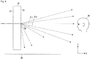
- Fig. 4 are shown a transparent section and an obstacle section of the screen 20.
- the haze in a lateral direction related to the transparent section is determined to be a haze to light, which enters into the first surface 21 or the rear side of the screen from the lateral direction and emits from the second surface 22 or the front side of the screen in the lateral direction.
- the haze in a downward direction related to the obstacle section is determined to be a haze to light, which enters into the first surface 21 or the rear side of the screen from an upward direction and emits from the second surface 22 or the front side of the screen in a downward direction.
- a transparent section Tr1 in the lateral direction shown in Fig. 4 is in a range of 15 degrees above to 20 degrees below with respect to the horizontal direction.
- the haze in the lateral direction may be defined as the haze in this section.
- the haze in the lateral direction is preferably at most 40%, more preferably at most 30%, furthermore preferably at most 20%, most preferably at most 10% in the transparent section Tr1.
- the haze referred to here is a haze to light that passes through both of the first scattering layer 24 and the second scattering layer 27.
- the haze is an index related to the transparency of a film.
- the haze represents a turbidity (clouding degree) of a film.
- the haze is found based on the proportion of diffuse transmitted light to total transmitted light according to the following formula.
- the haze is affected by the surface roughness of a film.
- a transparent section Tr2 in the lateral direction shown in Fig. 4 is in a range of 8 degrees above to 12 degrees below with respect to the lateral direction.
- the haze in the lateral direction may be defined as the haze in this section.
- the haze in the lateral direction is preferably at most 30%, more preferably at most 20%, furthermore preferably at most 10%, most preferably at most 5% in the transparent section Tr2.
- the haze referred to here is a haze to light that passes through both of the first scattering layer 24 and the second scattering layer 27.
- the obstacle section Ob in a downward direction shown in Fig. 4 is a section effective within at least 44 degrees.
- the obstacle section Ob is in a range of 20 degrees below to 81 degrees below with respect to the horizontal direction.
- the clouding degree in the downward direction is preferably at least 50%, more preferably at least 60%, most preferably at least 70% in the obstacle section Ob.
- the "value of turbidity” is a concept that is different from the haze.
- the haze represents a clouding degree with respect to an incident angle of 0 degree (at 90 degrees to the interface) while the "value of turbidity” is a value depending on an incident angle.
- the measure of a value of turbidity is made such that a sample is placed at a position of about 50 mm closer to a light source from the incident port of the integrating sphere of a haze meter, and light flux is measured with the sample being rotated to vary the angle of the sample surface to the optical axis.
- the clouding degree depending on an incident angle thus obtained is determined as the value of turbidity.
- the value of turbidity at each incident angle is represented by the following formula: 100 ⁇ 1 ⁇ light flux having an inclination angle within ⁇ 8.5 degrees to optical axis / light flux having an inclination angle within ⁇ 1.7 degrees to optical axis % .
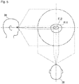
- FIG. 5 is shown the visual field of the observer 30 who watches the screen 20 in the horizontal direction.
- a visual field Fi1 ranges from 15 degrees above and 20 degrees below with respect to the horizontal direction and has a greater range than 15 degrees in right and left. Wider areas than the visual field Fi1 are called a stably gazing field, a guiding visual field and an auxiliary visual field according to enlargement in some cases.
- the stably gazing field is supposed to be an area where an observer can gaze comfortably by eye movement or head motion to receive information effectively.
- Fig. 5 is also shown a visual field Fi2 ranging from 8 degrees above and 12 degrees below, and from 15 degrees in left and 15 degrees in right with respect to the horizontal direction.
- the visual field Fi2 is an area called an effective visual field.
- the effective visual field is supposed to be an area where an observer can instantly receive information only by eye movement.
- the observer 30 can see a sight on the rear side of the screen 20 through the screen in particular an area in a perpendicular direction in the visual field Fi1 of the observer 30 shown in Fig. 5 .
- the observer 30 can see a sight on the rear side of the screen 20 through the screen in particular an area in the perpendicular direction in the visual field Fi2 of the observer 30 shown in Fig. 5 .
- the background light passing through the obstacle section Ob shown in Fig. 4 is not normally observed in particular an area in the perpendicular direction in the visual field Fi1 of the observer 30 shown in Fig. 5 .
- the scattering anisotropy caused by the screen is hardly to be an obstacle when the observer 30 sees a sight on the rear side of the screen 20 through the screen.
- a screen 20 which is formed in a plate shape.
- the screen 20 includes a screen body 40 and the second scattering layer 27.
- the screen body 40 includes a transparent plate 37a, a transparent plate 37b and the first scattering layer 24.
- the screen body 40 may be a transmitting type transparent member for image display disclosed in Patent Document 1.
- a plus Z direction is defined as a right side.
- the right side means a right area on the basis of the front side of the screen 20.
- a minus Z direction is defined as a left side.
- the left side means a left side on the basis of the front side of the screen 20.
- the transparent plate 37a shown in Fig. 6 is disposed on a rear side of the first scattering layer 24.
- the transparent plate 37b is disposed on a front side of the first scattering layer 24.
- the first scattering layer 24 is disposed between the transparent plates 37a and 37b.
- the transparent plates 37a and 37b are preferably made of glass.
- the second scattering layer 27 and the first scattering layer 24 confront each other, interposing the transparent plate 37b therebetween.
- the second scattering layer 27 shown in Fig. 6 may be bonded, as a film, to the transparent plate 37b.
- An anisotropic light-diffusing film having a louver structure as disclosed in Patent Document 3 may be advantageously used as the second scattering layer 27.
- a volume hologram, an arrangement where layer structures having different refractive indices from the transparent plate in a non-parallel direction are laminated as layers, or an arrangement where pillar structures having different refractive indices from the transparent plate in a non-parallel direction are arrayed in an inclination manner is also applicable.
- the screen body 40 shown in Fig. 6 has a certain forward haze.
- the forward haze means the proportion of light deviated by at least 0.044 rad (2.5 degrees) from the traveling direction of the light by so-called forward scattering, among the transmitted light traveling from a first surface 21 to a second surface 22 of the transparent screen 20.
- the forward scattering may be represented by percentage (%).
- the forward scattering may be a so-called usual haze which is measured by the method described in JIS K7136: 2000 (ISO 14782: 1999).
- the screen body 40 shown in Fig. 6 has a forward haze of preferably at least 4%, more preferably at least 5%.
- the screen 20 can be provided with preferred screen gain and viewing angle.
- the screen body 40 shown in Fig. 6 has a forward haze of preferably at most 40%, more preferably at most 30%.
- the haze is at most 40%, the visibility of a sight visible on the opposite side of the screen 20 as viewed from the observer is further improved.
- the screen body 40 as a forward haze of preferably at most 40%.
- the screen body 40 shown in Fig. 6 has a certain transmittance.
- the transmittance represents the ratio of a total amount of light passing through the screen body 40 or scattered at the screen body 40 and further emitting from the second surface 22 of the screen body 40, to an amount of light entering into the first surface 21 of the screen body 40.
- the transmittance may be represented by percentage (%).
- the screen body 40 has a transmittance of preferably at least 1 %, more preferably at least 5%. When the transmittance is at least 1 %, the visibility of a sight visible on the opposite side of the screen 20 as viewed from the observer is improved.
- Fig. 7 is shown an image display system 45.
- the above-mentioned screen 20 may be utilized as a reflective transparent screen by reversing the front and rear sides thereof.
- the image display system 45 shown in Fig. 7 includes the screen 20.
- the screen 20 receives image light 25 from the front side.
- the screen 20 returns the image light 25 toward the front side.
- the screen has a first surface 21 facing the front side.
- the screen has a second surface 22 facing the rear side.
- the screen 20 shown in Fig. 7 may provide diffuse reflection.
- the diffuse reflection may be isotropic.
- the screen may be a screen with no diffuse reflection, such as a retroreflective screen or a specular-diffuse screen.
- the retroreflective screen or the specular-diffuse screen may be isotropic.
- the image light 25 shown in Fig. 7 is incident from an upward direction on the front side of the screen.
- the image light 25 is reflected at the first scattering layer 24.
- the image light 25 is scattered to produce scattering light 48.
- the image light 25 is projected on the screen 20.
- Part of the image light 25 shown in Fig. 7 emits as transmitted light 49a in a downward direction from the rear side of the first scattering layer 24 without being scattered at the first scattering layer.
- the transmitted light 49a enters into the front side of the second scattering layer 27 from an upward direction.
- the transmitted light 49a passes through the second scattering layer 27.
- the transmitted light 49a is scattered at the second scattering layer 27.
- the transmitted light 49a emits as scattered light 49b in a downward direction from the rear side of the second scattering layer 27.
- background light 41 which travels in a lateral direction, passes through the second scattering layer 27 without being substantially scattered.
- the background light 41 that has passed through the second scattering layer 27 passes through the first scattering layer 24 without being substantially scattered.
- the image display system 45 shown in Fig. 7 can minimize the occurrence of the trouble where part of the image light 25 that is not projected on the screen 20 is projected on a ground 26 on the opposite side of the screen 20 in the incoming direction of the image light 25.
- the screen 20 shown in Fig. 3 or Fig. 7 cannot be utilized as a reflective transparent screen
- the screen 20 may be utilized as a transmitting type transparent screen as described above.
- the screen 20 may be utilized as a transmitting type transparent screen as described above.
- a screen 50 as a transparent screen.
- the screen 50 has a certain anisotropy with respect to light emitting from the screen 50.
- a screen 50 is disposed perpendicularly to a horizontal ground 26 as an example.
- the screen 50 is disposed so as to exhibit an anisotropy in upward and downward directions.
- the screen 50 may be disposed in a direction other than the perpendicular direction.
- the screen 50 may be disposed so as to exhibit an anisotropy in a direction other than the upward or downward direction.
- the screen 50 shown in Fig. 8 includes a first surface 51 and a second surface 52 as a rear side of the first surface 51.
- the screen 50 includes a scattering layer 54 and louvers 57 serving as an absorber layer.
- the scattering layer 54 shown in Fig. 8 is a layer which is disposed at a central portion of the screen 50.
- the scattering layer 54 may be an outermost layer on the first surface 51.
- the scattering layer 54 serves a function of projecting image light on the screen 50.
- the light scattering at the scattering layer 54 is preferably isotropic.
- the scattering layer 54 may be replaced by the first scattering layer 24 described above.
- the louvers 57 shown in Fig. 8 provide the screen 50 with a certain anisotropy.
- the louvers 57 are ones formed on the second surface 52.
- the louvers 57 are successively disposed on the second surface 52 from upward to downward.
- the louvers 57 are black.
- the image light 25 shown in Fig. 8 is scattered at the scattering layer 54.
- the image light 25 can be projected on the screen 50.
- Downward scattered light 58a produced by the scattering enters into the louvers 57 from an upward direction.
- Upward scattered light 58c enters into the louvers 57 from a downward direction. The energies of the scattered light 58a and the scattered light 58c are absorbed into the louvers 57 and are eliminated.
- scattered light 58b in a lateral direction produced by the scattering, and the louvers 57 are directed to the same direction.
- the scattered light 58b is not substantially absorbed into the louvers 57.
- the scattered light 58a is absorbed more than the scattered light 58b.
- Part of the image light 25 shown in Fig. 8 reaches, as transmitted light 59, the louvers 57 without being scattered at the scattering layer 54.
- the louvers 57 absorb the transmitted light 59.
- the louvers 57 shown in Fig. 8 transmit background light 31 in the lateral direction.
- the louvers 57 absorb background light entering into the screen 50 in a downward direction or an upward direction.
- the louvers 57 also serves as an anisotropic filter for peep prevention.
- a screen body 60 includes a scattering layer 54 in an example.
- a film 56 includes the absorber layer including the louvers 57.
- the screen 50 may be formed by bonding the film 56 to the screen body 60.
- the screen body 60 may be replaced by the above-mentioned screen body 40.
- the screen 50 shown in Fig. 8 can minimize the occurrence of the trouble where part of image light 25 that is not projected on the screen 50 is projected on the ground 26 on the opposite side of the screen 50 in the incoming direction of the image light 25.
- the screen 50 shown in Fig. 8 is a transmitting type screen.
- the screen 50 may be a reflective screen.
- the first surface 51 serves as a surface where the image light 25 emits.
- the second surface 52 serves as a surface where the image light 25 emits.
- the screen 50 When the screen 50 shown in Fig. 8 cannot be utilized as a reflective transparent screen, the screen 50 may be utilized as a transmitting type transparent screen as described above. Likewise, when the screen 50 cannot be utilized as a transmitting type transparent screen, the screen 50 may be utilized as a reflective transparent screen as described above.
- the transparent screen shown in each of the Figures may be utilized such that the front and rear sides are reversed.
- the transparent screen which has the front side facing the plus X direction, may be disposed so as to have the front side facing the minus X direction.
- the image light is projected on the front side of a transmitting type screen. Light emitting from the rear side of the screen reaches an observer.
- the image light is projected on the rear side of the screen, and light emitting from the rear side reaches the observer.
- the screen 20 When the screen 20 is seen from the front, the screen 20 is rectangular as shown in Fig. 6 .
- the shape of the transparent screen is not limited to be rectangular.
- the wording "rectangular" include a square.
- the direction where the transparent screen exhibits an anisotropy does not depend on the outer shape of the transparent screen. For example, even when the transparent screen is rectangular, the direction where the anisotropy is exhibited may be vertical, transverse or slant.
- the image display system shown in each of the Figures may be disposed in any one of structures including an architecture, a vehicle, a ship and an airplane.
- the architecture may be disposed on another architecture.
- the vehicle may be a rolling stock or an automobile.
- the automobile may be a bus.
- the transparent screen may be disposed in an opening of a structure.
- the transparent screen may be utilized as a window, which separates the inside and outside of a structure.
- the image display system may be utilized as digital signage.
- the digital signage may be disposed in or outside any one of the above-mentioned structures.
- the digital signage includes an image display system incorporated into any one of the above-mentioned structures.
- An image may be displayed toward outside an architecture by projecting image light on a window disposed in the architecture.
- the transparent screen may be disposed at a site where outdoor light is available.
- the outdoor light includes direct sunlight and scattered sunlight in the atmosphere or environment.
- the image display system may display an image toward outside a structure.
- the projector When the outdoor light downpours from an upward direction, the projector preferably projects image light toward the transparent screen from an upward direction as shown in each of the Figures. When there is no outdoor light as at night, the projector may project image light toward the transparent screen from a downward direction as described above.
- a transparent screen is designed to fabricate a transmitting type image display system 35 as shown in Fig. 6 .
- a vision control film which is supplied by Lintec Corporation under the product name Y-2555, is utilized as a second scattering layer 27.
- the vision control film is bonded, as the second scattering layer 27, to a front surface of a screen body 40.
- the bonding direction of the film is selected such that image light 28a emitting from the screen body 40 in a downward direction is selectively scattered.
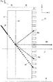
- FIG. 9 is shown a cross-sectional view of the second scattering layer 27, which is made of the vision control film.
- a vision control film has a louver structure where two kinds of layers having different refractive indices are alternately laminated. In the louver structure, these layers are disposed to be inclined.
- the louver structure has a laminating direction crossing with a thickness direction of the film.
- the two kinds of layers have some inclination angles from 64 to 68 degrees on the basis of the longitudinal direction of the film (Y axis direction). The inclination may change halfway in the thickness direction of the film.
- the vision control film (the second scattering layer 27) is bonded to the screen body 40 indicated by a solid line in Fig. 9 .
- the vision control film may be bonded so as to have a larger louver inclination angle side facing the screen body 40 or a smaller louver inclination angle side facing the screen body 40.
- the vision control film (second scattering layer 27) has the plus X direction extending in a direction away from the front surface of the transparent screen.
- the vision control film (second scattering layer 27) has the plus Y direction extending toward a top side of the transparent screen.
- the vision control film (second scattering layer 27) has the minus Y direction directed toward a bottom side of the transparent screen.
- the image light enters into the louver structure from the minus X direction in Fig. 9 .
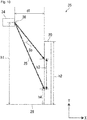
- the positional relationship between the screen 20 and the projector 34 is determined as shown in Fig. 10 .
- the distance d1 between the screen 20 and the projector 34 is 110 mm.
- the projector 34 includes a lens 36 having the center apart from a ground 26 by a distance h1 of 250 mm.
- the screen 20 has a height h2 of 200 mm.
- the screen has a projection area having a height h3 of 130 mm.
- the projection area ranges from 65 mm above to 65 mm below with respect to the center of the screen 20.
- the projection area has a lower end apart from the ground 26 by a distance h4 of 35 mm.
- the image light 25 has a diffusion angle Sp of about 25 degrees.
- the above-mentioned positional relationship may be properly modified because the diffusion angle Sp varies on a projector selected as the projector 34.
- the diffusion angle Sp of the projector may be selected in a range of at least 25 degrees to at most 44 degrees for example. Keystone correction may be used to remove a distortion in a projected image.
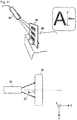
- a screen 20 and a projector 34 as viewed in a plan view.
- image light 25 is projected on a rear side of the screen 20 from a plus Y direction as shown in the lower part of Fig. 11 .
- the image light 25 has an optical axis forming an angle Ax of 90 degrees with the screen 20.
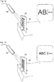
- the image projected on the screen 20 shown in Fig. 11 as a schematic view includes alphabetical characters.
- characters projected on the rear side of the screen 20 When the screen 20 was observed from the front side of the screen, it was seen that the characters were projected in a reverse manner. This is also applicable to Figs. 12 to 16 .
- the projected image has a character size of 40 mm.
- the ratio of the character size to the distance to a table surface 26 is 0.5.
- the ratio is 1.0 at a lower part of the screen.
- the distance to the table surface 26 means a distance from a character projected on the screen 20 by the projector 34 to a point where an extension of a straight line connecting between the emission port of the projector and the character projected on the screen crosses the table surface.
- the projected characters have a size of 20 mm.
- the ratio of the character size to the distance to the table surface 26 is 0.25.
- the projected characters have a size of 10 mm.
- the ratio of the character size to the distance to the table surface 26 is 0.1.
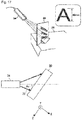
- a screen 20 and a projector 34 as viewed in a plan view.
- image light 25 is projected on a rear side of the screen 20 from a plus Y direction and a plus Z direction as shown in the lower part of Fig. 17 .
- the image light 25 has an optical axis forming an angle Ax of 40 degrees to 45 degrees with the screen 20.
- Fig. 17 the image light passes through the screen 20 and reaches a table surface.
- Character profiles can be seen based on shades projected on a portion of the table surface 26 close to the screen 20. No character profile is, however, seen in other portions on the table surface 26.
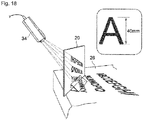
- Fig. 18 image light passes through the screen 20 and reaches the table surface 26. Character profiles can be seen in any of shades projected on the table surface 26. By comparing Fig. 17 with Fig. 18 , it is concluded that downward image light is scattered by a vision control film . Further, by comparing Fig. 11 with Fig. 17 , it is determined that such effect can be obtained even when image light is projected from a right or left oblique direction.
- the transparent screen 20 shown in Fig. 10 is disposed such that light entering into the second scattering layer from an upward direction is scattered more strongly than light entering into the second scattering layer from a lateral direction (see Figs. 2 and 3 ).
- the projector 34 projects the image light 25 on the rear surface of the screen from an upward direction within 40 degrees in left and right on the side of the rear surface.
- the transparent screen 20 shown in Fig. 10 may be disposed upside down so as to be turned over from the shown state such that light entering from a downward direction is scattered more strongly than light entering from a lateral direction in the second scattering layer.
- the projector projects image light on the rear surface of the screen from a downward direction within 40 degrees in left and right on the side of the rear surface.
Landscapes
- Physics & Mathematics (AREA)
- General Physics & Mathematics (AREA)
- Optics & Photonics (AREA)
- Engineering & Computer Science (AREA)
- Multimedia (AREA)
- Signal Processing (AREA)
- Optical Elements Other Than Lenses (AREA)
- Overhead Projectors And Projection Screens (AREA)
- Projection Apparatus (AREA)
Applications Claiming Priority (2)
| Application Number | Priority Date | Filing Date | Title |
|---|---|---|---|
| JP2017197937 | 2017-10-11 | ||
| JP2018165261A JP2019074730A (ja) | 2017-10-11 | 2018-09-04 | 透明スクリーン |
Publications (2)
| Publication Number | Publication Date |
|---|---|
| EP3470892A2 true EP3470892A2 (de) | 2019-04-17 |
| EP3470892A3 EP3470892A3 (de) | 2019-07-17 |
Family
ID=63578988
Family Applications (1)
| Application Number | Title | Priority Date | Filing Date |
|---|---|---|---|
| EP18193913.3A Withdrawn EP3470892A3 (de) | 2017-10-11 | 2018-09-12 | Transparenter schirm |
Country Status (2)
| Country | Link |
|---|---|
| US (1) | US20190107653A1 (de) |
| EP (1) | EP3470892A3 (de) |
Families Citing this family (3)
| Publication number | Priority date | Publication date | Assignee | Title |
|---|---|---|---|---|
| FR3067476B1 (fr) * | 2017-06-07 | 2019-10-18 | Saint-Gobain Glass France | Ecran de projection de couleur foncee ou noir |
| JPWO2023176022A1 (de) * | 2022-03-17 | 2023-09-21 | ||
| JP2023148723A (ja) * | 2022-03-30 | 2023-10-13 | リンテック株式会社 | 視野角制御フィルム |
Citations (4)
| Publication number | Priority date | Publication date | Assignee | Title |
|---|---|---|---|---|
| JP2003294952A (ja) | 2002-03-29 | 2003-10-15 | Denso Corp | ホログラムスクリーン |
| WO2013108540A1 (ja) | 2012-01-19 | 2013-07-25 | リンテック株式会社 | 異方性光拡散フィルム |
| WO2015199026A1 (ja) | 2014-06-23 | 2015-12-30 | 旭硝子株式会社 | 映像表示透明部材、映像表示システムおよび映像表示方法 |
| JP2017197937A (ja) | 2016-04-26 | 2017-11-02 | 株式会社ケーブイケー | 水栓及び浄水カートリッジ |
Family Cites Families (24)
| Publication number | Priority date | Publication date | Assignee | Title |
|---|---|---|---|---|
| US2089351A (en) * | 1935-04-23 | 1937-08-10 | Jack Pearson | Light diffusing material |
| US5040870A (en) * | 1989-10-13 | 1991-08-20 | Sumitomo Chemical Company, Limited | Screen for projection |
| US5148309A (en) * | 1990-12-14 | 1992-09-15 | Toppan Printing Co., Ltd. | Reflective type screen |
| US6381068B1 (en) * | 1999-03-19 | 2002-04-30 | 3M Innovative Properties Company | Reflective projection screen and projection system |
| US6804053B2 (en) * | 1999-12-22 | 2004-10-12 | Kimoto Co., Ltd. | See-through light transmitting type screen |
| JP2002318311A (ja) * | 2001-04-20 | 2002-10-31 | Clariant (Japan) Kk | 制御された散乱・透過特性を有する光学フィルム |
| US7046443B2 (en) * | 2002-07-24 | 2006-05-16 | Nitto Denko Corporation | Anisotropic light scattering element, anisotropic light scattering polarizing plate using the same, and image display device using the same |
| JP4749011B2 (ja) * | 2004-04-09 | 2011-08-17 | 直史 山内 | スクリーン及びこれを用いた画像投影システム |
| DE102004044802A1 (de) * | 2004-09-13 | 2006-03-30 | X3D Technologies Gmbh | Anordnung zur wahlweise dreidimensional wahrnehmbaren oder zweidimensionalen Darstellung von Bildern |
| JP4704739B2 (ja) * | 2004-11-10 | 2011-06-22 | 直史 山内 | スクリーン及びこれを用いた画像投影システム |
| JP2007206569A (ja) * | 2006-02-03 | 2007-08-16 | Daicel Chem Ind Ltd | 光学シート |
| US7784954B1 (en) * | 2006-07-25 | 2010-08-31 | Fusion Optix, Inc. | Polarization sensitive light homogenizer |
| US8223431B2 (en) * | 2007-03-30 | 2012-07-17 | Lg Electronics Inc. | Reflective screen and manufacturing method thereof |
| WO2009016975A1 (ja) * | 2007-08-02 | 2009-02-05 | Daicel Chemical Industries, Ltd. | 光拡散フィルム及びそれを備えた装置 |
| CN102159974B (zh) * | 2008-08-07 | 2013-04-17 | 东洋纺织株式会社 | 各向异性光扩散膜、各向异性光扩散层叠体、各向异性光反射层叠体及其用途 |
| US8068277B2 (en) * | 2008-11-26 | 2011-11-29 | Lg Electronics Inc. | Reflective type screen using a spacer layer |
| US9958580B2 (en) * | 2012-11-29 | 2018-05-01 | Tomoegawa Co., Ltd. | Anisotropic optical film |
| JP2014197163A (ja) * | 2013-01-17 | 2014-10-16 | 株式会社ダイセル | 半透明拡散型偏光積層体及びその用途 |
| US9563114B2 (en) * | 2013-05-20 | 2017-02-07 | Sharp Kabushiki Kaisha | Display device |
| JP6149006B2 (ja) * | 2014-06-18 | 2017-06-14 | 富士フイルム株式会社 | 反射フィルムおよび反射フィルムを有するディスプレイ |
| CN107077058B (zh) * | 2014-10-27 | 2019-06-14 | Agc株式会社 | 透射型透明屏幕、影像显示系统和影像显示方法 |
| WO2017038452A1 (ja) * | 2015-09-03 | 2017-03-09 | 旭硝子株式会社 | 透明スクリーン、透明スクリーン組立体、透明スクリーンの製造方法、および透明スクリーン組立体の製造方法 |
| WO2017146093A1 (ja) * | 2016-02-25 | 2017-08-31 | 日華化学株式会社 | 反射型スクリーン及び反射型スクリーン用シート |
| CN110462456B (zh) * | 2017-03-31 | 2021-11-26 | 株式会社巴川制纸所 | 防眩性膜以及显示装置 |
-
2018
- 2018-09-12 EP EP18193913.3A patent/EP3470892A3/de not_active Withdrawn
- 2018-09-13 US US16/129,954 patent/US20190107653A1/en not_active Abandoned
Patent Citations (4)
| Publication number | Priority date | Publication date | Assignee | Title |
|---|---|---|---|---|
| JP2003294952A (ja) | 2002-03-29 | 2003-10-15 | Denso Corp | ホログラムスクリーン |
| WO2013108540A1 (ja) | 2012-01-19 | 2013-07-25 | リンテック株式会社 | 異方性光拡散フィルム |
| WO2015199026A1 (ja) | 2014-06-23 | 2015-12-30 | 旭硝子株式会社 | 映像表示透明部材、映像表示システムおよび映像表示方法 |
| JP2017197937A (ja) | 2016-04-26 | 2017-11-02 | 株式会社ケーブイケー | 水栓及び浄水カートリッジ |
Also Published As
| Publication number | Publication date |
|---|---|
| EP3470892A3 (de) | 2019-07-17 |
| US20190107653A1 (en) | 2019-04-11 |
Similar Documents
| Publication | Publication Date | Title |
|---|---|---|
| JP7667843B2 (ja) | 表示装置 | |
| JP7587652B2 (ja) | 表示装置 | |
| JP5471821B2 (ja) | 視野角制御シート | |
| JP4536626B2 (ja) | 表示装置 | |
| JP7282174B2 (ja) | 情報表示システム | |
| JP6372305B2 (ja) | 死角補助装置 | |
| JP6638450B2 (ja) | 空中映像表示装置 | |
| CN1680870B (zh) | 屏幕以及使用其的图像投影系统 | |
| CN102495475A (zh) | 图像显示装置 | |
| EP3088252A1 (de) | Totwinkel-assistent | |
| CN103383516B (zh) | 投影系统 | |
| US20190107653A1 (en) | Transparent screen | |
| KR101241494B1 (ko) | 디스플레이용 윈드 실드 글라스 및 그 제조 방법 | |
| WO2021139995A1 (en) | Glass vehicle side window and partition window with active projection transparent screen | |
| JP6405627B2 (ja) | 死角補助装置 | |
| JP2016109778A (ja) | 透過型透明スクリーン、映像表示システムおよび映像表示方法 | |
| JP6299471B2 (ja) | 死角補助装置 | |
| JP2019074730A (ja) | 透明スクリーン | |
| JP2014186249A (ja) | スクリーンユニット、マルチスクリーン、背面投射型表示装置 | |
| JP6986218B2 (ja) | 表示装置 | |
| KR100837486B1 (ko) | 시야각 제어 시트 및 표시 장치 | |
| JPH0358080A (ja) | ヘッドアップディスプレイ | |
| JP7009779B2 (ja) | 表示装置 | |
| JP7232432B2 (ja) | 表示装置 | |
| KR101627241B1 (ko) | 광각 투명 패널을 이용한 차량용 광각형 사이드미러장치 |
Legal Events
| Date | Code | Title | Description |
|---|---|---|---|
| PUAI | Public reference made under article 153(3) epc to a published international application that has entered the european phase |
Free format text: ORIGINAL CODE: 0009012 |
|
| AK | Designated contracting states |
Kind code of ref document: A2 Designated state(s): AL AT BE BG CH CY CZ DE DK EE ES FI FR GB GR HR HU IE IS IT LI LT LU LV MC MK MT NL NO PL PT RO RS SE SI SK SM TR |
|
| AX | Request for extension of the european patent |
Extension state: BA ME |
|
| PUAL | Search report despatched |
Free format text: ORIGINAL CODE: 0009013 |
|
| AK | Designated contracting states |
Kind code of ref document: A3 Designated state(s): AL AT BE BG CH CY CZ DE DK EE ES FI FR GB GR HR HU IE IS IT LI LT LU LV MC MK MT NL NO PL PT RO RS SE SI SK SM TR |
|
| AX | Request for extension of the european patent |
Extension state: BA ME |
|
| RIC1 | Information provided on ipc code assigned before grant |
Ipc: G02B 5/02 20060101AFI20190613BHEP |
|
| STAA | Information on the status of an ep patent application or granted ep patent |
Free format text: STATUS: THE APPLICATION IS DEEMED TO BE WITHDRAWN |
|
| 18D | Application deemed to be withdrawn |
Effective date: 20200118 |