EP3469331B1 - Probenentnahmevorrichtung zur entnahme von getränkeproben aus einer getränkeleitung, die ein unter druck stehendes gashaltiges getränk enthält - Google Patents
Probenentnahmevorrichtung zur entnahme von getränkeproben aus einer getränkeleitung, die ein unter druck stehendes gashaltiges getränk enthält Download PDFInfo
- Publication number
- EP3469331B1 EP3469331B1 EP17729105.1A EP17729105A EP3469331B1 EP 3469331 B1 EP3469331 B1 EP 3469331B1 EP 17729105 A EP17729105 A EP 17729105A EP 3469331 B1 EP3469331 B1 EP 3469331B1
- Authority
- EP
- European Patent Office
- Prior art keywords
- line
- valve
- pump chamber
- beverage
- shut
- Prior art date
- Legal status (The legal status is an assumption and is not a legal conclusion. Google has not performed a legal analysis and makes no representation as to the accuracy of the status listed.)
- Active
Links
Images

Classifications
-
- G—PHYSICS
- G01—MEASURING; TESTING
- G01N—INVESTIGATING OR ANALYSING MATERIALS BY DETERMINING THEIR CHEMICAL OR PHYSICAL PROPERTIES
- G01N1/00—Sampling; Preparing specimens for investigation
- G01N1/02—Devices for withdrawing samples
- G01N1/10—Devices for withdrawing samples in the liquid or fluent state
- G01N1/20—Devices for withdrawing samples in the liquid or fluent state for flowing or falling materials
- G01N1/2035—Devices for withdrawing samples in the liquid or fluent state for flowing or falling materials by deviating part of a fluid stream, e.g. by drawing-off or tapping
-
- G—PHYSICS
- G01—MEASURING; TESTING
- G01N—INVESTIGATING OR ANALYSING MATERIALS BY DETERMINING THEIR CHEMICAL OR PHYSICAL PROPERTIES
- G01N1/00—Sampling; Preparing specimens for investigation
- G01N1/02—Devices for withdrawing samples
- G01N1/10—Devices for withdrawing samples in the liquid or fluent state
- G01N1/14—Suction devices, e.g. pumps; Ejector devices
-
- G—PHYSICS
- G01—MEASURING; TESTING
- G01N—INVESTIGATING OR ANALYSING MATERIALS BY DETERMINING THEIR CHEMICAL OR PHYSICAL PROPERTIES
- G01N1/00—Sampling; Preparing specimens for investigation
- G01N1/02—Devices for withdrawing samples
- G01N1/10—Devices for withdrawing samples in the liquid or fluent state
- G01N1/20—Devices for withdrawing samples in the liquid or fluent state for flowing or falling materials
-
- G—PHYSICS
- G01—MEASURING; TESTING
- G01N—INVESTIGATING OR ANALYSING MATERIALS BY DETERMINING THEIR CHEMICAL OR PHYSICAL PROPERTIES
- G01N1/00—Sampling; Preparing specimens for investigation
- G01N1/28—Preparing specimens for investigation including physical details of (bio-)chemical methods covered elsewhere, e.g. G01N33/50, C12Q
- G01N1/34—Purifying; Cleaning
-
- G—PHYSICS
- G01—MEASURING; TESTING
- G01N—INVESTIGATING OR ANALYSING MATERIALS BY DETERMINING THEIR CHEMICAL OR PHYSICAL PROPERTIES
- G01N33/00—Investigating or analysing materials by specific methods not covered by groups G01N1/00 - G01N31/00
- G01N33/02—Food
- G01N33/14—Beverages
- G01N33/146—Beverages containing alcohol
-
- G—PHYSICS
- G01—MEASURING; TESTING
- G01N—INVESTIGATING OR ANALYSING MATERIALS BY DETERMINING THEIR CHEMICAL OR PHYSICAL PROPERTIES
- G01N1/00—Sampling; Preparing specimens for investigation
- G01N1/02—Devices for withdrawing samples
- G01N1/10—Devices for withdrawing samples in the liquid or fluent state
- G01N2001/1031—Sampling from special places
- G01N2001/105—Sampling from special places from high-pressure reactors or lines
-
- G—PHYSICS
- G01—MEASURING; TESTING
- G01N—INVESTIGATING OR ANALYSING MATERIALS BY DETERMINING THEIR CHEMICAL OR PHYSICAL PROPERTIES
- G01N1/00—Sampling; Preparing specimens for investigation
- G01N1/02—Devices for withdrawing samples
- G01N1/10—Devices for withdrawing samples in the liquid or fluent state
- G01N1/20—Devices for withdrawing samples in the liquid or fluent state for flowing or falling materials
- G01N1/2035—Devices for withdrawing samples in the liquid or fluent state for flowing or falling materials by deviating part of a fluid stream, e.g. by drawing-off or tapping
- G01N2001/205—Devices for withdrawing samples in the liquid or fluent state for flowing or falling materials by deviating part of a fluid stream, e.g. by drawing-off or tapping using a valve
- G01N2001/2057—Sample chamber in a valve/piston
Definitions
- the invention relates to a sampling device for taking beverage samples from a beverage line which contains a pressurized gas-containing beverage.
- sampling device which has a connection for a beverage line that contains a C0 2 -containing beverage
- Sampling device has a pump with a pump cylinder in which a movable piston is arranged so that it can move back and forth between two end positions.
- the piston divides the pump cylinder into two fluid spaces that are sealed from one another.
- One fluid chamber serves as a pump chamber and can be connected to the connection for the beverage line via a directional control valve.
- the other fluid space is connected to a compressed air line which is connected to a compressed air source via a pressure regulator.
- the piston is under the liquid pressure of a line system connected to the connection for the beverage line and, on the other hand, under the gas pressure of the compressed air line.
- the pressure in the beverage line forces the beverage sample through the line system into the cylinder, with the piston moving to the other end stop depending on the set differential pressure, without the C0 2 ⁇ containing beverage sample having the opportunity to degas or foam.
- the multi-way valve then closes the connection between the pump chamber and the connection for the beverage line and connects the sample chamber via an emptying line to a delivery opening so that the beverage sample can be pressed out of the cylinder with the help of compressed air.
- the piping system also has a vent line with an outlet opening.
- a sampling device which has a pump which draws a sample liquid from a pipe section Processing system sucks into a vertical pipe section of the bypass system. A first valve is then closed to create a vacuum in the sample liquid using the pump. After a second valve is closed, the sample liquid is compressed in the pipe section using a piston. The properties of the sample liquid are then measured using a measuring device. The sample can then be returned to the processing facility. By applying the vacuum to the sample liquid and then compressing the sample liquid, any gas bubbles contained in the sample liquid are removed from the sample liquid.
- a milk collecting device with an air separator is known.
- negative pressure can be applied to it using a vacuum pump.
- the milk has the opportunity to degas or separate from air components.
- a milk collecting device with an air separator is known. This has a container under negative pressure, which is equipped with a delivery line for milk conveyed with the inclusion of air and foam.
- a sampling device which has a connection for a beverage line of a beverage production system.
- a gas-containing beverage under pressure such as beer flows through the beverage line.
- the connection for the beverage line is connected via a supply line to a delivery opening for the beverage sample, which is connected to an inlet opening of a flow measuring cell of an infrared spectrometer is.
- a coarse particle filter is arranged in the supply line, which has a pore size between 1 ⁇ m and 0.1 mm.
- the outlet opening of the flow measuring cell is connected to an outlet for the beverage sample via a fluid line in which a conductivity sensor, a pH sensor, a turbidity sensor, a needle valve, a shut-off valve and a suction pump are arranged.
- a return line branches off from the fluid line between the turbidity sensor and the needle valve. If necessary, the beverage sample can be returned to the production process via the return line. However, this does not correspond to the safety requirements to be applied in the production of food according to the guidelines of the European Hygienic Engineering & Design Group (EHEDG), according to which no liquids from the sampling device may flow back into the beverage line of the food filling facility.
- EHEDG European Hygienic Engineering & Design Group
- the needle valve arranged behind the flow measuring cell in the flow direction and the shut-off valve arranged behind it in the flow direction serve to maintain a pressure of 2 to 5 atmospheres in the flow measuring cell when analyzing carbonated drinks.
- pressure-sensitive analysis devices such as the QFOOD QUANTOS ® are not suitable for such high pressures.
- the sampling device can also be used under normal pressure conditions if the needle valve and/or the shut-off valve are opened.
- this has the disadvantage that gas bubbles can then form in the beverage sample, which can cause malfunctions of the analysis device, especially if the beverage sample is transported through very thin fluid channels and / or a flow measuring cell in which the beverage sample is arranged between parallel and small distances walls forms a thin layer.
- the previously known chromatography device is intended for examining blood samples and has a separation column connected to the delivery opening, on which an analyte contained in the blood sample is adsorbed. This is removed from the separation column using the eluent and then examined chromatographically.
- the object is therefore to create a robustly constructed sampling device by means of which a beverage sample can be easily removed from a beverage line containing a pressurized gas-containing beverage and fed to an infrared spectrometer under normal pressure at a delivery opening. Gas bubbles in the beverage sample should be avoided at the delivery opening.
- the sampling device should also enable low-maintenance and trouble-free operation.
- the pump room advantageously fulfills a double function in which it serves, on the one hand, to degas the beverage sample and, on the other hand, is used to transport the degassed beverage sample from the pump room to the delivery opening for the beverage sample.
- This enables a simple and robust construction of the sampling device. Since the beverage sample is delivered at the delivery opening essentially under atmospheric pressure, the sampling device can also be combined with analysis devices in which the analyte must have no or only a very low excess pressure. Because the beverage sample is degassed before it reaches the dispensing opening, and the gas that has escaped from the beverage sample and is located in the upper part of the pump chamber is discharged via the outlet opening, gas bubbles are formed in the beverage sample at the dispensing opening, which can lead to malfunctions of the analyzer. avoided.
- the pump is preferred as a syringe pump or designed as a piston pump. This measure also enables a simple and robust design of the sampling device.
- the sampling device for filtering the beverage sample has a particle filter with an inlet and an outlet for the beverage sample, the line system being connected to the inlet of the particle filter, the outlet of the particle filter and a supply line for a backwash medium that is in the fourth valve configuration the pump chamber is connected to the discharge opening via the particle filter, that in the first, second, third and fourth valve configuration the pump chamber is separated from the supply line for the backwashing medium, that in a fifth valve configuration the supply line for the backwashing medium is connected to the outlet opening via the particle filter is, and that the control device is in control connection with the valves in such a way that the fifth valve configuration is set after step iv) of claim 1 for backwashing the particle filter.
- the particle filter prevents any particles contained in the beverage sample from reaching the delivery opening for the sample and thus into an analysis device connected to it that is intended to examine the beverage sample. Since the particle filter is automatically backwashed after use, particles that are retained from the beverage sample by the particle filter can be easily removed from the particle filter and discharged from the sampling device via the outlet opening. This enables low-maintenance and trouble-free operation of the sampling device.
- control device is designed such that steps ii) and iii) from claim 1 are repeated at least once before step iv) from claim 1 is carried out. This allows the gas content of the beverage sample to be further reduced.
- the pump chamber is preferably separated from the inlet of the particle filter. This prevents gas bubbles from getting into the particle filter from the pump room. Even in the first one Valve configuration, the pump chamber can be separated from the inlet of the particle filter.
- the particle filter has a pre-filter and a fine filter connected in series with it, the inlet of the particle filter being arranged on the pre-filter and the outlet of the particle filter being arranged on the fine filter.
- the fine filter can be used to filter out particles up to a size of preferably 0.4 ⁇ m from the beverage sample.
- the pre-filter upstream of the fine filter filters out larger particles from the beverage sample. This increases the service life of the fine filter.
- connection for the beverage line is connected to the pump room via a first line, a first shut-off valve being arranged in the first line, the pump room being connected via a second line which opens into the pump room or at an intermediate
- This and the first shut-off valve arranged first branch point is connected to the first line, is connected to a first fluid port of a first three-way valve, and wherein a second fluid port of the first three-way valve is connected to the outlet opening and a third fluid port of the first three-way valve is connected to the inlet of the particle filter .
- the three-way valve enables a simple construction of the pipe system.
- connection for the beverage line is connected to the pump room via a first line, a first shut-off valve being arranged in the first line, the pump room being connected via a second line which opens into the pump room or on a
- the first branch point arranged between this and the first shut-off valve is connected to the first line, is connected to the inlet of the particle filter, a second shut-off valve being arranged in the second line, and wherein on the pump room and / or on the first line between the pump room and a connection point is provided on the first shut-off valve and/or on the second line between the pump chamber and the second shut-off valve, which is connected to the outlet opening for the waste via a third shut-off valve.
- the first three-way valve two shut-off valves can also be provided.
- the sampling device according to the invention is preferably designed to be compatible with the guidelines of the European Hygienic Engineering & Design Group (EHEDG).
- EHEDG European Hygienic Engineering & Design Group
- the sampling device can be designed such that no liquids that are arranged behind the first shut-off valve in the sampling device can flow back into the beverage line. This can be achieved by ensuring that the first shut-off valve is always closed when the pump chamber is compressed.
- At least one sensor connected to the control device for detecting the drink is arranged in the line system between the connection for the beverage line and the inlet of the particle filter and/or between the pump chamber and the inlet of the particle filter, the control device being designed in this way that the inlet of the particle filter is shut off by means of the first three-way valve or the second shut-off valve if the sensor does not detect the drink.
- the inlet of the particle filter is blocked when the sensor comes into contact with a gas and/or with a cleaning, disinfection and/or rinsing liquid is carried out by the beverage management as part of a cleaning in place cleaning process (CIP).
- CIP cleaning in place cleaning process
- the sampling device according to the invention is therefore also suitable for use in production systems that are cleaned or disinfected using the CIP cleaning process.
- the sensor expediently has a conductivity sensor and/or a pH value sensor. This enables a cost-effective design of the sensor.
- the outlet of the particle filter is connected to a first fluid connection of a second three-way valve, a second fluid connection of the second three-way valve being connected to the delivery opening for the beverage sample and a third fluid connection of the second three-way valve being connected to the supply line for the backwashing medium.
- the second three-way valve enables a simple construction of the line system.
- the outlet of the particle filter is connected to the delivery opening for the beverage sample via a third line in which a fourth shut-off valve is arranged, and that there is a second branching point between the outlet of the particle filter and the fourth shut-off valve is arranged, on which the third line is connected via a fifth shut-off valve to the supply line for the backwashing medium.
- a fourth shut-off valve is arranged in which a fourth shut-off valve is arranged, and that there is a second branching point between the outlet of the particle filter and the fourth shut-off valve is arranged, on which the third line is connected via a fifth shut-off valve to the supply line for the backwashing medium.
- two shut-off valves can also be provided.
- connection for the beverage line is connected to the pump room via a first line, that the first shut-off valve and a sixth shut-off valve are connected in series in the first line, that the pump room or an intermediate
- the first branching point provided in the first line, the sixth shut-off valve and the pump chamber is connected to the inlet of the particle filter via the second line, and that a third branching point is arranged between the first shut-off valve and the sixth shut-off valve, at which the first line is connected via a fourth line , in which a seventh shut-off valve is arranged, is connected to the outlet opening or a further outlet opening for waste.
- the first, sixth and seventh shut-off valves can be configured by means of the control device in such a way that the first and seventh shut-off valves are opened and the sixth shut-off valve is closed.
- the cleaning, disinfection and/or rinsing liquid can then flow from the connection for the beverage line via the first shut-off valve and the first line to the third branch point and from there via the fourth line and the seventh shut-off valve to the outlet opening. Since the sixth shut-off valve is blocked in this configuration, the cleaning, disinfection and/or rinsing liquid cannot reach either the pump room or the particle filter.
- the first and sixth shut-off valves are open and the seventh shut-off valve is closed. If necessary, the first, sixth and seventh shut-off valves can also be adjusted via the control device so that the seventh shut-off valve is opened and the first and sixth shut-off valves are closed. This means that no liquid can flow back from the pump room into the beverage line even if the first and/or sixth shut-off valve should leak.
- the sampling device designated overall as 1, is used to remove beverage samples from a beverage line 2 in a beverage production plant.
- a pressurized gaseous beverage is arranged in the beverage line 2, for example beer or a carbonated lemonade.
- the sampling device 1 has an in Fig. 1 Connection 3, shown only schematically, which is firmly connected to the beverage line 2.
- the connection 3 is connected via a line system which has adjustable valves by means of actuators not shown in the drawing, with a pump chamber 4 of a pump 5, a particle filter 8 having an inlet 6 and an outlet 7 for filtering the beverage sample, an outlet opening 9 for waste, a delivery opening 10 for the beverage sample and a feed line 11 for a backwash medium.
- An analysis device not shown in the drawing, which is used to examine the beverage sample, such as the QFOOD QUANTOS® , can be connected to the delivery opening 10.
- the pump 5 is designed as a syringe pump which has a piston 13 which is axially displaceable in a cylinder 12 and which can be adjusted by means of a drive 14 which is only shown schematically in the drawing.
- the cylinder 12 and the piston 13 delimit a pump chamber 4, which is delimited at its upper end by an upper wall 16, at its lower end by a lower wall 17 formed by the piston 13 and laterally by the inner wall of the cylinder 12, which Pump room 4 delimited.
- the piston 13 can be moved toward and away from the upper wall 16 by means of the drive 14.
- connection 3 for the beverage line 2 is connected to the upper end of the pump chamber 4 via a first line 19. It can be clearly seen that the first line 19 opens into the pump chamber 4 on the upper wall 16.
- a first shut-off valve 20 is arranged close to the connection 3, by means of which the first line 19 can be shut off from the beverage line 2.
- the first line 19 has a first branching point, at which the first line 19 is connected via a second line 21 to a first fluid connection 22 of a first three-way valve 23.
- a second fluid connection 24 of the first three-way valve 23 is connected to the outlet opening 9 for the waste and a third fluid connection 25 of the first three-way valve 23 is connected to the inlet 6 of the particle filter 8.
- the outlet 7 of the particle filter 8 is connected to a first fluid connection 26 of a second three-way valve 27, a second fluid connection 28 of the second three-way valve 27 is connected to the delivery opening 10 for the beverage sample and a third connection 29 of the second three-way valve 27 is connected to the supply line 11 for the backwash medium tied together.
- the sampling device 1 has a second and a third shut-off valve 30, 31 instead of the first three-way valve.
- the second shut-off valve 30 is arranged between the first line 19 and the particle filter 8 in the second line 21.
- the second line 21 has a connection point between the first line 19 and the second shut-off valve 30, which is connected to the outlet opening 9 for the waste via the third shut-off valve 31.
- the outlet 7 of the particle filter 8 is connected to the delivery opening 10 for the beverage sample via a third line 32, in which a fourth shut-off valve 33 is arranged.
- a second branching point is arranged between the outlet 7 of the particle filter 8 and the fourth shut-off valve 33, at which the third line 32 is connected to the supply line 11 for the backwashing medium via a fifth shut-off valve 34.
- the control device 18 is in control connection with the shut-off valves 20, 30, 33, 34 and the drive 14 of the pump 5 in such a way that the above-mentioned steps i) to vi) are carried out.
- the second exemplary embodiment essentially corresponds to the exemplary embodiment Fig. 1 .
- the third exemplary embodiment shown essentially corresponds to the first exemplary embodiment, but additionally has a sixth and a seventh shut-off valve 35, 37.
- the sixth shut-off valve 35 is arranged in the first line 19 between the first shut-off valve 20 and the first branch point at which the second line 21 branches off from the first line 19.
- a third branch point is arranged between the first shut-off valve 20 and the sixth shut-off valve 35, at which the first line 19 is connected to a further outlet opening 9 'for waste via a fourth line 36, in which a seventh shut-off valve 37 is arranged.
- the first, sixth and seventh shut-off valves 20, 35, 37 are configured in such a way that the first and seventh shut-off valves 20, 37 are opened and the sixth shut-off valve 35 is closed.
- the first and sixth shut-off valves 20, 35 are open and the seventh shut-off valve 37 is closed.
- the sampling device 1 has the second and third shut-off valves 30, 31 instead of the first three-way valve 23.
- the second shut-off valve 30 is arranged between the first branch point and the particle filter 8 in the second line 21.
- the second line 21 has a connection point between the first line 19 and the second shut-off valve 30, which is connected to the outlet opening 9 for the waste via the third shut-off valve 31.
- the outlet 7 of the particle filter 8 is connected to the delivery opening 10 for the beverage sample via the third line 32, in which the fourth shut-off valve 33 is arranged. Between the outlet 7 of the particle filter 8 and the fourth shut-off valve 33, the second branching point is arranged, at which the third line 32 is connected to the feed line 11 for the backwashing medium via the fifth shut-off valve 34.
- the particle filter 8 has a pre-filter 8a and a fine filter 8b, which is arranged behind the pre-filter 8a in the flow direction of the beverage sample.
- the fine filter 8b has a smaller average pore diameter than the pre-filter 8a.
- the fourth exemplary embodiment essentially corresponds to the exemplary embodiment Fig. 3 .
- a sensor 15 for detecting the drink which is connected to the control device 18 and is designed as a pH value sensor, is arranged in the second line 21 between the first line 19 and the third shut-off valve.
- the measurement signal from the sensor 15 is compared in the control device 18 with a reference range in which the measurement signal lies when the sensor 15 is in contact with the beverage sample. If the sensor 15 is in contact with the gas emerging from the beverage sample and/or with the cleaning, disinfection and/or rinsing liquid, the measurement signal of the sensor 15 deviates from the reference range. In this case, the second shut-off valve 30 is locked in the closed position. This prevents gas, cleaning, disinfection and/or rinsing liquid from entering the particle filter 8. Otherwise, the fifth exemplary embodiment corresponds to the exemplary embodiment Fig. 4 .
- the management system of the in Fig. 6 corresponds to that in Fig. 3 , but without the first three-way valve 23, ie the first line 19 is in Fig. 6 connected directly to the inlet 6 of the particle filter 8.
- the first and sixth shut-off valves 20, 35 are opened and the seventh shut-off valve 37 is closed to introduce the beverage sample into the pump room 4.
- the pump chamber 4 is separated from the delivery opening 10 for the beverage sample and the supply line 11 for the backwashing medium by the second three-way valve 27.
- the sixth shut-off valve 35 is closed to degas the beverage sample located in the pump room 4 and the pump room 4 is further separated from the delivery opening 10 and the supply line 11 by the second three-way valve 27.
- the first shut-off valve 20 is closed and the sixth and seventh shut-off valves 35, 37 are opened so that the gas can be drained from the pump chamber 4 to the waste outlet opening 9 arranged behind the seventh shut-off valve 37.
- the pump chamber 4 is further separated from the delivery opening 10 and the supply line 11 via the second three-way valve 27.
- the first shut-off valve 20 is closed and the pump chamber 4 is connected to the discharge opening 10 via the pre-filter 8a, the fine filter 8b and the second three-way valve 27.
- the supply line 11 for the backwashing medium is connected to the outlet 7 of the fine filter 8b via the second three-way valve 27 and the inlet of the pre-filter 8a is connected to the outlet 9 for the waste via the sixth and seventh shut-off valves 35, 37.
- the delivery opening 10 is through second Three-way valve 27 separated from the supply line 11 and the outlet 7 of the fine filter 8b.
- the first shut-off valve 20 is closed.
Landscapes
- Life Sciences & Earth Sciences (AREA)
- Health & Medical Sciences (AREA)
- Chemical & Material Sciences (AREA)
- Biochemistry (AREA)
- General Physics & Mathematics (AREA)
- Pathology (AREA)
- Physics & Mathematics (AREA)
- Analytical Chemistry (AREA)
- Immunology (AREA)
- General Health & Medical Sciences (AREA)
- Hydrology & Water Resources (AREA)
- Engineering & Computer Science (AREA)
- Food Science & Technology (AREA)
- Medicinal Chemistry (AREA)
- Biomedical Technology (AREA)
- Molecular Biology (AREA)
- Sampling And Sample Adjustment (AREA)
Description
- Die Erfindung betrifft eine Probenentnahmevorrichtung zur Entnahme von Getränkeproben aus einer Getränkeleitung, die ein unter Druck stehendes gashaltiges Getränk enthält.
- Eine solche Probenentnahmevorrichtung, die einen Anschluss für eine Getränkeleitung aufweist, welche ein C02-haltiges Getränk enthält, ist aus
DE 39 20 949 A1 bekannt. Probenentnahmevorrichtung weist eine Pumpe mit einem Pumpenzylinder auf, in dem ein beweglicher Kolben zwischen zwei Endlagen hin- und her bewegbar angeordnet ist. Der Kolben unterteilt den Pumpenzylinder in zwei gegeneinander abgedichtete Fluidräume. Der eine Fluidraum dient als Pumpenraum und ist über ein Wegeventil mit dem Anschluss für die Getränkeleitung verbindbar. Der andere Fluidraum ist mit einer Druckluftleitung verbunden, die über einen Druckregler an einer Druckluftquelle angeschlossen ist. Der Kolben steht einerseits unter dem Flüssigkeitsdruck eines mit dem Anschluss für die Getränkeleitung verbundenen Leitungssystems und andererseits unter dem Gasdruck der Druckluftleitung. Durch den Druck in der Getränkeleitung wird die Getränkeprobe durch das Leitungssystem hindurch in den Zylinder gedrückt, wobei sich der Kolben je nach eingestelltem Differenzdruck bis zum anderen Endanschlag bewegt, ohne dass die C02·haltige Getränkeprobe die Möglichkeit hat, zu entgasen oder zu schäumen. Danach schließt das Mehrwegeventil die Verbindung zwischen dem Pumpenraum und dem Anschluss für die Getränkeleitung und verbindet den Probenraum über eine Entleerungsleitung mit einer Abgabeöffnung, so dass die Getränkeprobe aus dem Zylinder mit Hilfe der Druckluft herausgedrückt werden kann. Das Leitungssystem hat außerdem eine Entlüftungsleitung mit einer Auslassöffnung. - Aus der
WO 2004/034035 A1 ist eine Probenentnahmevorrichtung bekannt, die eine Pumpe aufweist, die eine Probenflüssigkeit aus einem Rohrabschnitt einer Verarbeitungsanlage in ein vertikales Rohrstück des Bypass-Systems saugt. Dann wird ein erstes Ventil geschlossen, um mit Hilfe der Pumpe ein Vakuum in der Probenflüssigkeit zu erzeugen. Nachdem ein zweites Ventil wird geschlossen wurde, wird die Probenflüssigkeit mit Hilfe eines Kolbens in dem Rohrstück komprimiert. Danach werden die Eigenschaften der Probenflüssigkeit mittels einer Messvorrichtung gemessen. Die Probe kann dann wieder an die Verarbeitungsanlage zurückgegeben werden. Durch das Anlegen des Vakuums an die Probenflüssigkeit und das anschließende Komprimieren der Probenflüssigkeit werden eventuelle, in der Probenflüssigkeit enthaltene Gasblasen aus der Probenflüssigkeit entfernt. - Aus der
DE 20 2014 106 092 U1 ist eine Milchsammelvorrichtung mit einem Luftabscheider bekannt. Zur Einsaugung der Milch in den Luftabscheider ist dieser über eine Vakuumpumpe mit Unterdruck beaufschlagbar. Während ihrer Verweilzeit im Luftabscheidebehälter hat die Milch Gelegenheit zu entgasen bzw. sich von Luftbestandteilen zu trennen. - Auch aus der
EP 1 035 407 A2 ist eine Milchsammelvorrichtung mit einem Luftabscheider bekannt. Dieser hat einen unter Unterdruck stehenden Behälter, der mit einer Förderleitung für unter Einschluss von Luft und Schaum geförderte Milch. - Aus der
EP 0 367 899 A1 ist Anordnung bekannt, bei der eine Durchflussleitung an einen Luftabscheider angeschlossenen, dessen Kopfraum mit einer Unterdruckquelle in Verbindung steht. - Aus
DE 103 52 924 A1 ist ferner eine Probenentnahmevorrichtung bekannt, die einen Anschluss für eine Getränkeleitung einer Getränke-Produktionsanlage hat. Durch die Getränkeleitung fließt ein unter Druck stehendes gashaltiges Getränk, wie zum Beispiel Bier. Der Anschluss für die Getränkeleitung ist über eine Zuleitung mit einer Abgabeöffnung für die Getränkeprobe verbunden, die an einer Einlassöffnung einer Durchflussmesszelle eines Infrarot-Spektrometers angeschlossen ist. Zwischen dem Anschluss für die Getränkeleitung und der Abgabeöffnung ist ein Grobpartikelfilter in der Zuleitung angeordnet, der eine Porengröße zwischen 1 µm und 0,1 mm aufweist. Die Auslassöffnung der Durchflussmesszelle ist über eine Fluidleitung, in der ein Leitfähigkeitssensor, ein pH-Sensor, ein Trübungssensor, ein Nadelventil, ein Absperrventil und eine Ansaugpumpe angeordnet sind, mit einem Auslass für die Getränkeprobe verbunden. Zwischen dem Trübungssensor und dem Nadelventil zweigt eine Rücklaufleitung von der Fluidleitung ab. Über die Rücklaufleitung kann die Getränkeprobe bei Bedarf in den Produktionsprozess zurückgeführt werden. Dies entspricht jedoch nicht den bei der Herstellung von Lebensmitteln anzuwendenden Sicherheitsauflagen gemäß den Leitlinien des European Hygienic Engineering & Design Group (EHEDG), wonach keine Flüssigkeiten aus der Probenentnahmevorrichtung zurück in die Getränkeleitung der Lebensmittelabfülleinrichtung gelangen dürfen. Das in Strömungsrichtung hinter der Durchflussmesszelle angeordnete Nadelventil und das in Strömungsrichtung hinter diesem angeordnet Absperrventil dienen dazu, in der Durchflussmesszelle bei der Analyse von kohlensäurehaltigen Getränken einen Druck von 2 bis 5 Atmosphären aufrecht zu erhalten. Druckempfindliche Analysegeräte, wie z.B. das QFOOD QUANTOS® sind jedoch für so hohe Drücke nicht geeignet. Mit der Probenentnahmevorrichtung kann zwar auch unter normalen Druckbedingungen gearbeitet werden, wenn das Nadelventil und/oder das Absperrventil geöffnet werden. Dies hat aber den Nachteil, dass sich dann Gasblasen in der Getränkeprobe bilden können, die Funktionsstörungen des Analysegeräts verursachen können, insbesondere wenn die Getränkeprobe durch sehr dünne Fluidkanäle und/oder eine Durchflussmesszelle transportiert wird, in der die Getränkeprobe zwischen in geringem Abstand parallel zueinander angeordneten Wänden eine dünne Schicht bildet. - Aus der
US 2013/0319087 A1 ist eine Chromatographievorrichtung bekannt, die eine Probenentnahmevorrichtung zur Entnahme von Proben aus einer Leitung aufweist, die mit einem Vorratsbehälter für einen Eluent verbunden ist, wobei die Probenentnahmevorrichtung - einen Anschluss für die Leitung,
- eine Pumpe mit einem Pumpenraum hat, der durch Wandungen begrenzt ist, die zum Expandieren und Komprimieren des Pumpraums mittels des Antriebs aufeinander zu- und voneinander wegbewegbar sind,
- eine Abgabeöffnung für die Probe,
- ein verstellbare Ventile aufweisendes Leitungssystem, welches mit dem Anschluss für die Leitung, dem Pumpenraum der Abgabeöffnung und einer Auslassöffnung für Abfall verbunden ist, und
- eine Steuereinrichtung hat,
- i) dass in einer ersten Ventilkonfiguration, bei welcher der Pumpenraum mit dem Anschluss für die Leitung verbunden und von der Auslassöffnung sowie der Abgabeöffnung getrennt ist, eine Probe, deren Volumen kleiner ist als das maximale Volumen des Pumpenraums, vom Anschluss für die Leitung in den Pumpenraum einbringbar ist,
- ii) dass danach eine zweite Ventilkonfiguration eingestellt wird, in welcher der Pumpenraum vom Anschluss für die Leitung, von der Auslassöffnung sowie der Abgabeöffnung getrennt ist, und der Pumpenraum derart expandiert wird, dass zum Entgasen der Probe ein Unterdruck im Pumpenraum entsteht,
- iii) dass danach eine dritte Ventilkonfiguration eingestellt wird, in welcher der Pumpenraum mit der Auslassöffnung verbunden und von dem Anschluss für die Leitung sowie der Abgabeöffnung getrennt ist, und der Pumpenraum derart komprimiert wird, dass ein in einem oberen Teil des Pumpenraums befindliches erstes Teilvolumen zu der Auslassöffnung hin verdrängt und ein in einem unteren Teil des Pumpenraums befindliches zweites Teilvolumen im Pumpenraum verbleibt,
- iv) dass danach eine vierte Ventilkonfiguration eingestellt, in welcher der Pumpenraum über den Partikelfilter mit der Abgabeöffnung verbunden und von dem Anschluss für die Leitung, der Zuleitung für das Rückspülmedium sowie der Auslassöffnung getrennt ist, und der Pumpenraum zum Verdrängen der darin befindlichen Probe zur Abgabeöffnung hin weiter komprimiert wird.
- Die vorbekannte Chromatographievorrichtung ist zum Untersuchen von Blutproben vorgesehen und weist eine mit der Abgabeöffnung verbundene Trennsäule auf, an der ein in der Blutprobe enthaltener Analyt adsorbiert wird. Dieser wird mittels des Eluents aus der Trennsäule herausgelöst und danach chromatographisch untersucht.
- Es besteht deshalb die Aufgabe, eine robust aufgebaute Probenentnahmevorrichtung zu schaffen, mittels der auf einfache Weise aus einer Getränkeleitung, die ein unter Druck stehendes gashaltiges Getränk enthält, eine Getränkeprobe entnehmbar und unter Normaldruck an einer Abgabeöffnung einem Infrarotspektrometer zuführbar ist. Dabei sollen an der Abgabeöffnung Gasblasen in der Getränkeprobe vermieden werden. Die Probenentnahmevorrichtung soll außerdem einen wartungsarmen und störungsfreien Betrieb ermöglichen.
- Erfindungsgemäß wird diese Aufgabe mit den Merkmalen des Anspruchs 1 gelöst.
- In Vorteilhafter Weise erfüllt der Pumpenraum dabei eine Doppelfunktion, bei welcher er einerseits zum Entgasen der Getränkeprobe dient und andererseits für den Transport der entgasten Getränkeprobe vom Pumpenraum zu der Abgabeöffnung für die Getränkeprobe benutzt wird. Dies ermöglicht einen einfachen und robusten Aufbau der Probenentnahmevorrichtung. Da die Getränkeprobe an der Abgabeöffnung im Wesentlichen unter Atmosphärendruck abgegeben wird, kann die Probenentnahmevorrichtung auch mit Analysegeräten kombiniert werden, bei denen der Analyt keinen oder nur einen sehr geringen Überdruck aufweisen darf. Weil die Getränkeprobe entgast wird, bevor sie zu der Abgabeöffnung gelangt, und das aus der Getränkeprobe ausgetretene, im oberen Teil des Pumpenraums befindliche Gas über die Auslassöffnung abgeführt wird, werden an der Abgabeöffnung Gasblasen in der Getränkeprobe, die zu Funktionsstörungen des Analysegeräts führen können, vermieden. Die Pumpe ist bevorzugt als Spritzenpumpe oder als Kolbenpumpe ausgestaltet. Auch durch diese Maßnahme wird einsss einfacher und robuster Aufbau der Probenentnahmevorrichtung ermöglicht.
- Bei der Erfindung weist die Probenentnahmevorrichtung zum Filtern der Getränkeprobe einen Partikelfilter mit einem Einlass und einem Auslass für die Getränkeprobe auf, wobei das Leitungssystem mit dem Einlass des Partikelfilters, dem Auslass des Partikelfilters und einer Zuleitung für ein Rückspülmedium verbunden ist, dass in der vierten Ventilkonfiguration der Pumpenraum über den Partikelfilter mit der Abgabeöffnung verbunden ist, dass in der ersten, zweiten, dritten und vierten Ventilkonfiguration der Pumpenraum von der Zuleitung für das Rückspülmedium getrennt ist, dass in einer fünften Ventilkonfiguration die Zuleitung für das Rückspülmedium über den Partikelfilter mit der Auslassöffnung verbunden ist, und dass die Steuereinrichtung derart mit den Ventilen in Steuerverbindung steht, dass nach Schritt iv) aus Anspruch 1 zum Rückspülen des Partikelfilters die fünfte Ventilkonfiguration eingestellt wird. Durch den Partikelfilter wird verhindert, dass eventuelle, in der Getränkeprobe enthaltene Partikel zur Abgabeöffnung für die Probe und damit in ein daran angeschlossenes, zum Untersuchen der Getränkeprobe vorgesehenes Analysegerät gelangen können. Da der Partikelfilter nach Gebrauch automatisch rückgespült wird, können Partikel, die vom Partikelfilter aus der Getränkeprobe zurückgehalten werden, auf einfache Weise wieder aus dem Partikelfilter entfernt und über die Auslassöffnung aus der Probenentnahmevorrichtung abgeführt werden. Dies ermöglicht einen wartungsarmen und störungsfreien Betrieb der Probenentnahmevorrichtung.
- Bei einer bevorzugten Ausgestaltung der Erfindung ist die Steuereinrichtung derart ausgestaltet, dass die Schritte ii) und iii) aus Anspruch 1 mindestens einmal wiederholt werden, bevor Schritt iv) aus Anspruch 1 durchgeführt wird. Dadurch kann der Gasgehalt der Getränkeprobe weiter reduziert werden.
- Bevorzugt ist in der zweiten und/oder dritten Ventilkonfiguration der Pumpenraum vom Einlass des Partikelfilters getrennt. Dadurch wird verhindert, dass Gasblasen aus dem Pumpenraum in den Partikelfilter gelangen können. Auch in der ersten Ventilkonfiguration kann der Pumpenraum vom Einlass des Partikelfilters getrennt sein.
- Bei einer vorteilhaften Ausführungsform der Erfindung weist der Partikelfilter einen Vorfilter und einen damit in Reihe geschalteten Feinfilter auf, wobei der Einlass des Partikelfilters am Vorfilter und der Auslass des Partikelfilters am Feinfilter angeordnet ist. Durch den Feinfilter können Partikel bis zu einer Größe von vorzugsweise 0,4 µm aus der Getränkeprobe herausgefiltert werden. Der dem Feinfilter vorgeschaltete Vorfilter filtert größere Partikel aus der Getränkeprobe heraus. Dadurch wird die Standzeit des Feinfilters vergrößert.
- Bei einer bevorzugten Ausgestaltung der Erfindung ist der Anschluss für die Getränkeleitung über eine erste Leitung mit dem Pumpenraum verbunden ist, wobei in der ersten Leitung ein erstes Absperrventil angeordnet ist, wobei der Pumpenraum über eine zweite Leitung, die in den Pumpenraum mündet oder an einer zwischen diesem und dem ersten Absperrventil angeordneten ersten Verzweigungsstelle an der ersten Leitung angeschlossen ist, mit einem ersten Fluidanschluss eines ersten Dreiwegeventils verbunden ist, und wobei ein zweiter Fluidanschluss des ersten Dreiwegeventils mit der Auslassöffnung und ein dritter Fluidanschluss des ersten Dreiwegeventils mit dem Einlass des Partikelfilters verbunden ist. Dabei ermöglicht das Dreiwegeventil einen einfachen Aufbau des Leitungssystems.
- Bei einer anderen zweckmäßigen Ausführungsform der Erfindung ist der Anschluss für die Getränkeleitung über eine erste Leitung mit dem Pumpenraum verbunden ist, wobei in der ersten Leitung ein erstes Absperrventil angeordnet ist, wobei der Pumpenraum über eine zweite Leitung, die in den Pumpenraum mündet oder an einer zwischen diesem und dem ersten Absperrventil angeordneten ersten Verzweigungsstelle an der ersten Leitung angeschlossen ist, mit dem Einlass des Partikelfilters verbunden ist, wobei in der zweiten Leitung ein zweites Absperrventil angeordnet ist, und wobei am Pumpenraum und/oder an der ersten Leitung zwischen dem Pumpenraum und dem ersten Absperrventil und/oder an der zweiten Leitung zwischen dem Pumpenraum und dem zweiten Absperrventil eine Anschlussstelle vorgesehen ist, die über ein drittes Absperrventil mit der Auslassöffnung für den Abfall verbunden ist. Anstelle des ersten Dreiwegeventils können also auch zwei Absperrventile vorgesehen sein.
- Die erfindungsgemäße Probenentnahmevorrichtung ist bevorzugt kompatibel zu den Leitlinien des European Hygienic Engineering & Design Group (EHEDG) ausgestaltet. Insbesondere kann die Probenentnahmevorrichtung derart ausgestaltet sein, dass keine Flüssigkeiten, die hinter dem ersten Absperrventil in der Probenentnahmevorrichtung angeordnet sind, in die Getränkeleitung zurück fließen können. Das kann dadurch erreicht werden, dass das erste Absperrventil beim Komprimieren des Pumpenraums stets geschlossen ist.
- Bei einer Weiterbildung der Erfindung ist in dem Leitungssystem zwischen dem Anschluss für die Getränkeleitung und dem Einlass des Partikelfilters und/oder zwischen dem Pumpenraum und dem Einlass des Partikelfilters mindestens ein mit der Steuereinrichtung verbundener Sensor zum Detektieren des Getränks angeordnet, wobei die Steuereinrichtung derart ausgestaltet ist, dass der Einlass des Partikelfilters mittels des ersten Dreiwegeventils oder des zweiten Absperrventils abgesperrt ist, wenn der Sensor das Getränk nicht detektiert. Der Einlass des Partikelfilters ist dann gesperrt ist, wenn der Sensor mit einem Gas und/oder mit einer Reinigungs-, Desinfektions- und/oder Spülflüssigkeit in Kontakt gerät, die im Rahmen eines Cleaning in Place Reinigungsverfahren (CIP) durch die Getränkeleitung geleitet wird. Mit Hilfe des in der Nahrungsmittelindustrie üblichen CIP Reinigungsverfahrens kann eine Produktionsanlage für Getränke ohne wesentliche Demontage auf den Flächen, die mit dem Getränk in Berührung gelangen, gereinigt werden. Die erfindungsgemäße Probenentnahmevorrichtung ist also auch für eine Verwendung in Produktionsanlagen geeignet, die mit dem CIP Reinigungsverfahren gereinigt bzw. desinfiziert werden.
- Zweckmäßigerweise weist der Sensor einen Leitfähigkeitssensor und/oder einen pH-Wertsensor auf. Dies ermöglicht eine kostengünstige Ausgestaltung des Sensors.
- Bei einer vorteilhaften Ausführungsform der Erfindung ist der Auslass des Partikelfilters mit einem ersten Fluidanschluss eines zweiten Dreiwegeventils verbunden, wobei ein zweiter Fluidanschluss des zweiten Dreiwegeventils mit der Abgabeöffnung für die Getränkeprobe und ein dritter Fluidanschluss des zweiten Dreiwegeventils mit der Zuleitung für das Rückspülmedium verbunden ist. Dabei ermöglicht das zweite Dreiwegeventil einen einfachen Aufbau des Leitungssystems.
- Bei einer anderen Ausgestaltung der Erfindung ist vorgesehen, dass der Auslass des Partikelfilters über eine dritte Leitung, in der ein viertes Absperrventil angeordnet ist, mit der Abgabeöffnung für die Getränkeprobe verbunden ist, und dass zwischen dem Auslass des Partikelfilters und dem vierten Absperrventil eine zweite Verzweigungsstelle angeordnet ist, an der die dritte Leitung über ein fünftes Absperrventil mit der Zuleitung für das Rückspülmedium verbunden ist. Anstelle des zweiten Dreiwegeventils können also auch zwei Absperrventile vorgesehen sein.
- Bei einer bevorzugten Ausgestaltung der Erfindung ist vorgesehen, dass der Anschluss für die Getränkeleitung über eine erste Leitung mit dem Pumpenraum verbunden ist, dass in der ersten Leitung das erste Absperrventil und ein sechstes Absperrventil in Reihe geschaltet sind, dass der Pumpenraum oder eine zwischen dem sechsten Absperrventil und dem Pumpenraum in der ersten Leitung vorgesehene erste Verzweigungsstelle über die zweite Leitung mit dem Einlass des Partikelfilters verbunden ist, und dass zwischen dem ersten Absperrventil und dem sechsten Absperrventil eine dritte Verzweigungsstelle angeordnet ist, an der die erste Leitung über eine vierte Leitung, in der ein siebtes Absperrventil angeordnet ist, mit der Auslassöffnung oder einer weiteren Auslassöffnung für Abfall verbunden ist.
- Dabei können das erste, sechste und siebte Absperrventil beim Durchleiten einer Reinigungs-, Desinfektions- und/oder Spülflüssigkeit durch die Getränkeleitung mittels der Steuereinrichtung derart konfiguriert werden, dass das erste und siebte Absperrventil geöffnet und das sechste Absperrventil geschlossen ist. Die Reinigungs-, Desinfektions- und/oder Spülflüssigkeit kann dann vom Anschluss für die Getränkeleitung über das erste Absperrventil und die erste Leitung zur dritten Verzweigungsstelle und von dort über die vierte Leitung und das siebte Absperrventil zur Auslassöffnung fließen. Da das sechste Absperrventil in dieser Konfiguration gesperrt ist, kann die Reinigungs-, Desinfektions- und/oder Spülflüssigkeit weder in den Pumpenraum noch in den Partikelfilter gelangen. In einer weiteren Konfiguration, die zum Befüllen des Pumpenraums mit der Getränkeprobe dient, sind das erste und sechste Absperrventil geöffnet und das siebte Absperrventil ist geschlossen. Bei Bedarf können das erste, sechste und siebte Absperrventil über die Steuereinrichtung auch so eingestellt werden, dass das siebte Absperrventil geöffnet und das erste und sechste Absperrventil geschlossen sind. Dadurch kann auch dann keine Flüssigkeit aus dem Pumpenraum in die Getränkeleitung zurückfließen, wenn das erste und/oder sechste Absperrventil einmal undicht werden sollten.
- Nachfolgend sind Ausführungsbeispiele der Erfindung anhand der Zeichnung näher erläutert. Es zeigt
- Fig. 1
- eine schematische Darstellung eines ersten Ausführungsbeispiels der Probenentnahmevorrichtung,
- Fig. 2
- eine schematische Darstellung eines zweiten Ausführungsbeispiels der Probenentnahmevorrichtung,
- Fig. 3
- eine schematische Darstellung eines dritten Ausführungsbeispiels der Probenentnahmevorrichtung,
- Fig. 4
- eine schematische Darstellung eines vierten Ausführungsbeispiels der Probenentnahmevorrichtung,
- Fig. 5
- eine schematische Darstellung eines fünften Ausführungsbeispiels der Probenentnahmevorrichtung, und
- Fig. 6
- eine schematische Darstellung eines sechsten Ausführungsbeispiels der Probenentnahmevorrichtung.
- Eine in
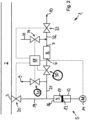
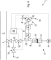
Fig. 1 im Ganzen mit 1 bezeichnete Probenentnahmevorrichtung dient zur Entnahme von Getränkeproben aus einer Getränkeleitung 2 in einer Getränkeproduktionsanlage. In der Getränkeleitung 2 ist ein unter Druck stehendes gashaltiges Getränk angeordnet, beispielsweise Bier oder eine kohlensäurehaltige Limonade. - Die Probenentnahmevorrichtung 1 hat einen in
Fig. 1 nur schematisch dargestellten Anschluss 3, der fest mit der Getränkeleitung 2 verbunden ist. Der Anschluss 3 ist über ein Leitungssystem das mittels in der Zeichnung nicht näher dargestellten Aktoren verstellbare Ventile aufweist, mit einem Pumpenraum 4 einer Pumpe 5, einem einen Einlass 6 und einen Auslass 7 aufweisenden Partikelfilter 8 zum Filtern der Getränkeprobe, einer Auslassöffnung 9 für Abfall, einer Abgabeöffnung 10 für die Getränkeprobe und einer Zuleitung 11 für ein Rückspülmedium verbunden. An der Abgabeöffnung 10 kann ein in der Zeichnung nicht näher dargestelltes Analysegerät, das zur Untersuchung der Getränkeprobe dient, angeschlossen sein, wie z.B. das QFOOD QUANTOS®. - Die Pumpe 5 ist als Spritzenpumpe ausgestaltet, die einen in einem Zylinder 12 axial verschiebbaren Kolben 13 aufweist, der mittels eines in der Zeichnung nur schematisch dargestellten Antriebs 14 verstellbar ist. Der Zylinder 12 und der Kolben 13 begrenzen einen Pumpenraum 4, der an seinem oberen Ende durch eine obere Wandung 16, an seinem unteren Ende durch eine durch den Kolben 13 gebildete untere Wandung 17 und seitlich durch die Innenwand des Zylinders 12 begrenzt wird, welche den Pumpenraum 4 umgrenzt. Zum Expandieren und Komprimieren des Pumpraums 4 ist der Kolben 13 mittels des Antriebs 14 auf die obere Wandung 16 zu- und von dieser wegbewegbar.
- Mit Hilfe der Ventile ist das Leitungssystem wie folgt konfigurierbar:
- I) In einer ersten Ventilkonfiguration ist der Pumpenraum 4 mit dem Anschluss 3 für die Getränkeleitung 2 verbunden und von der Auslassöffnung 9 für den Abfall, der Abgabeöffnung 10 für die Getränkeprobe sowie der Zuleitung 11 für das Rückspülmedium getrennt.
- II) In einer zweiten Ventilkonfiguration ist der Pumpenraum 4 vom Anschluss 3 für die Getränkeleitung, von der Auslassöffnung 9 für den Abfall, der Abgabeöffnung 10 für die Getränkeprobe sowie der Zuleitung 11 für das Rückspülmedium getrennt.
- III) In einer dritten Ventilkonfiguration ist der Pumpenraum 4 mit der Auslassöffnung 9 für den Abfall verbunden und von dem Anschluss 3 für die Getränkeleitung 2, der Abgabeöffnung 10 für die Getränkeprobe sowie der Zuleitung 11 für das Rückspülmedium getrennt.
- IV) In einer vierten Ventilkonfiguration ist der Pumpenraum 4 mit einem Einlass 6 des Partikelfilters 8 und der Auslass 7 des Partikelfilters 8 mit der Abgabeöffnung 10 für die Getränkeprobe verbunden. Außerdem ist der Pumpenraum 4 von dem Anschluss 3 für die Getränkeleitung 2, der Auslassöffnung 9 für den Abfall sowie der Zuleitung 11 für das Rückspülmedium getrennt.
- V) In einer fünften Ventilkonfiguration ist die Zuleitung 11 für das Rückspülmedium über den Partikelfilter 8 mit der Auslassöffnung 9 für den Abfall verbunden und vom Anschluss 3 für die Getränkeleitung 2, dem Pumpenraum 4 und der Abgabeöffnung 10 getrennt.
- Bei dem in
Fig. 1 gezeigten ersten Ausführungsbeispiel ist der Anschluss 3 für die Getränkeleitung 2 über eine erste Leitung 19 mit dem oberen Ende des Pumpenraums 4 verbunden. Deutlich ist erkennbar, dass die erste Leitung 19 in an der oberen Wandung 16 in den Pumpenraum 4 mündet. - In der ersten Leitung ist dicht benachbart zum Anschluss 3 ein erstes Absperrventil 20 angeordnet, mittels dem die erste Leitung 19 zur Getränkeleitung 2 hin abgesperrt werden kann. Zwischen dem ersten Absperrventil 20 und dem Pumpenraum 4 hat die erste Leitung 19 eine erste Verzweigungsstelle, an der die erste Leitung 19 über eine zweite Leitung 21 mit einem ersten Fluidanschluss 22 eines ersten Dreiwegeventils 23 verbunden ist. Ein zweiter Fluidanschluss 24 des ersten Dreiwegeventils 23 mit der Auslassöffnung 9 für den Abfall und ein dritter Fluidanschluss 25 des ersten Dreiwegeventils 23 ist mit dem Einlass 6 des Partikelfilters 8 verbunden.
- Der Auslass 7 Partikelfilters 8 ist mit einem ersten Fluidanschluss 26 eines zweiten Dreiwegeventils 27 verbunden, ein zweiter Fluidanschluss 28 des zweiten Dreiwegeventils 27 ist mit der Abgabeöffnung 10 für die Getränkeprobe und ein dritter Anschluss 29 des zweiten Dreiwegeventils 27 ist mit der Zuleitung 11 für das Rückspülmedium verbunden.
- Wie in
Fig. 1 erkennbar ist, weist die Probenentnahmevorrichtung 1 außerdem eine Steuereinrichtung 18 auf. Diese steht derart mit dem ersten Absperrventil 20, den Dreiwegeventilen 23, 27 und dem Antrieb 14 der Pumpe 5 in Steuerverbindung, dass folgende Schritte durchlaufen werden: - i) In der ersten Ventilkonfiguration wird eine Getränkeprobe, deren Volumen kleiner ist als das maximale Volumen des Pumpenraums 4, vom Anschluss 3 für die Getränkeleitung 2 in den Pumpenraum 4 eingebracht. Das kann beispielsweise dadurch erreicht werden, dass die erste Ventilkonfiguration für eine an das Volumen der Getränkeprobe und den Volumenstrom in der ersten Leitung 19 angepasste, vorbestimmte Zeitdauer eingestellt wird.
- ii) Danach wird eine zweite Ventilkonfiguration eingestellt und der Pumpenraum 4 wird derart expandiert wird, dass Gas aus der Getränkeprobe austritt. Dabei wird die Dauer, während welcher der Pumpenraum 4 expandiert ist, derart gewählt, dass Gas in nennenswerter Menge aus der Getränkeprobe austreten und in den oberhalb der Getränkeprobe befindlichen Teil des Pumpenraums 4 gelangen kann.
- iii) Danach wird die dritte Ventilkonfiguration eingestellt und der Pumpenraum 4 derart komprimiert wird, dass aus der Getränkeprobe ausgetretenes, im oberen Teil des Pumpenraums 4 befindliches Gas zur Auslassöffnung 9 für den Abfall hin verdrängt wird und die im unteren Teil des Pumpenraums 4 befindliche Getränkeprobe im Wesentlichen im Pumpenraum 4 verbleibt.
- iv) Die Schritte ii) und iii) aus Anspruch 1 werden mindestens einmal wiederholt.
- v) Danach wird die vierte Ventilkonfiguration eingestellt und der Pumpenraum 4 wird derart weiter komprimiert, dass die darin befindliche Getränkeprobe zur Abgabeöffnung 10 hin verdrängt wird. Dabei durchströmt die Getränkeprobe den Partikelfilter 8.
- vi) Danach wird zum Rückspülen des Partikelfilters 8 die fünfte Ventilkonfiguration eingestellt. Dabei fließt sauberes Wasser aus der Zuleitung 11 entgegen der Strömungsrichtung der Getränkeprobe durch den Partikelfilters 8 hindurch zur Auslassöffnung 9, wo es beispielsweise in die Kanalisation oder einen Auffangbehälter eingeleitet wird.
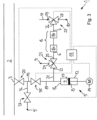
- Bei dem in
Fig. 2 abgebildeten zweiten Ausführungsbeispiel weist die Probenentnahmevorrichtung 1 anstelle des ersten Dreiwegeventils ein zweites und ein drittes Absperrventil 30, 31 auf. Das zweite Absperrventil 30 ist zwischen der ersten Leitung 19 und dem Partikelfilter 8 in der zweiten Leitung 21 angeordnet. Die zweite Leitung 21 weist zwischen der ersten Leitung 19 und dem zweiten Absperrventil 30 eine Anschlussstelle auf, die über das dritte Absperrventil 31 mit der Auslassöffnung 9 für den Abfall verbunden ist. - Der Auslass 7 des Partikelfilters 8 ist über eine dritte Leitung 32, in der ein viertes Absperrventil 33 angeordnet ist, mit der Abgabeöffnung 10 für die Getränkeprobe verbunden. Zwischen dem Auslass 7 des Partikelfilters 8 und dem vierten Absperrventil 33 ist eine zweite Verzweigungsstelle angeordnet, an der die dritte Leitung 32 über ein fünftes Absperrventil 34 mit der Zuleitung 11 für das Rückspülmedium verbunden ist.
- Die Steuereinrichtung 18 steht derart mit den Absperrventilen 20, 30, 33, 34 und dem Antrieb 14 der Pumpe 5 in Steuerverbindung, dass die oben genannten Schritte i) bis vi) durchlaufen werden. Im Übrigen entspricht das zweite Ausführungsbeispiel im Wesentlichen dem Ausführungsbeispiel aus
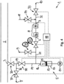
Fig. 1 . - Das in
Fig. 3 abgebildete dritte Ausführungsbeispiel entspricht im Wesentlichen dem ersten Ausführungsbeispiel, weist jedoch zusätzlich ein sechstes und ein siebtes Absperrventil 35, 37 auf. Das sechste Absperrventil 35 ist in der ersten Leitung 19 zwischen dem ersten Absperrventil 20 und der ersten Verzweigungsstelle angeordnet, an der die zweite Leitung 21 von der ersten Leitung 19 abzweigt. Zwischen dem ersten Absperrventil 20 und dem sechsten Absperrventil 35 ist eine dritte Verzweigungsstelle angeordnet, an der die erste Leitung 19 über eine vierte Leitung 36, in der ein siebtes Absperrventil 37 angeordnet ist, mit einer weiteren Auslassöffnung 9' für Abfall verbunden ist. Das erste, sechste und siebte Absperrventil 20, 35, 37 sind beim Durchleiten einer Reinigungs-, Desinfektions- und/oder Spülflüssigkeit durch die Getränkeleitung 2 derart konfiguriert, dass das erste und siebte Absperrventil 20, 37 geöffnet und das sechste Absperrventil 35 geschlossen ist. Zum Befüllen des Pumpenraums 4 mit der Getränkeprobe sind das erste und sechste Absperrventil 20, 35 geöffnet und das siebte Absperrventil 37 ist geschlossen. - Bei dem in
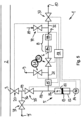
Fig. 4 abgebildeten vierten Ausführungsbeispiel weist die Probenentnahmevorrichtung 1 anstelle des ersten Dreiwegeventils 23 das zweite und dritte Absperrventil 30, 31 auf. Das zweite Absperrventil 30 ist zwischen der ersten Verzweigungsstelle und dem Partikelfilter 8 in der zweiten Leitung 21 angeordnet. - Die zweite Leitung 21 weist zwischen der ersten Leitung 19 und dem zweiten Absperrventil 30 eine Anschlussstelle auf, die über das dritte Absperrventil 31 mit der Auslassöffnung 9 für den Abfall verbunden ist.
- Der Auslass 7 des Partikelfilters 8 ist über die dritte Leitung 32, in der das vierte Absperrventil 33 angeordnet ist, mit der Abgabeöffnung 10 für die Getränkeprobe verbunden. Zwischen dem Auslass 7 des Partikelfilters 8 und dem vierten Absperrventil 33 ist die zweite Verzweigungsstelle angeordnet, an der die dritte Leitung 32 über das fünfte Absperrventil 34 mit der Zuleitung 11 für das Rückspülmedium verbunden ist.
- Bei dem vierten Ausführungsbeispiel weist der Partikelfilter 8 einen Vorfilter 8a und einen Feinfilter 8b auf, der in Strömungsrichtung der Getränkeprobe hinter dem Vorfilter 8a angeordnet ist. Der Feinfilter 8b hat einen geringeren mittleren Porendurchmesser als der Vorfilter 8a.
- Im Übrigen entspricht das vierte Ausführungsbeispiel im Wesentlichen dem Ausführungsbeispiel aus
Fig. 3 . - Bei dem in
Fig. 5 abgebildeten fünften Ausführungsbeispiel ist in der zweiten Leitung 21 zwischen der ersten Leitung 19 und dem dritten Absperrventil ein mit der Steuereinrichtung 18 verbundener Sensor 15 zum Detektieren des Getränks angeordnet, der als pH-Wertsensor ausgestaltet ist. Das Messsignal des Sensors 15 wird in der Steuereinrichtung 18 mit einem Referenzbereich verglichen, in dem das Messsignal liegt, wenn der Sensor 15 mit der Getränkeprobe in Kontakt steht. Wenn der Sensor 15 mit dem aus der Getränkeprobe ausgetretenen Gas und/oder mit der Reinigungs-, Desinfektions- und/oder Spülflüssigkeit in Kontakt steht, weicht das Messsignal des Sensors 15 von dem Referenzbereich ab. In diesem Fall ist das zweite Absperrventil 30 in der Schließstellung verriegelt. Dadurch wird verhindert, dass Gas, Reinigungs-, Desinfektions- und/oder Spülflüssigkeit in den Partikelfilter 8 gelangt. Im Übrigen entspricht das fünfte Ausführungsbeispiel dem Ausführungsbeispiel ausFig. 4 . - Das Leitungssystem des in
Fig. 6 abgebildeten sechsten Ausführungsbeispiels entspricht dem inFig. 3 , jedoch ohne das erste Dreiwegeventil 23, d.h. die erste Leitung 19 ist inFig. 6 direkt mit dem Einlass 6 des Partikelfilters 8 verbunden. - In der ersten Ventilkonfiguration sind zum Einbringen der Getränkeprobe in den Pumpenraum 4 des erste und sechste Absperrventil 20, 35 geöffnet und das siebte Absperrventil 37 ist geschlossen. Außerdem ist der Pumpenraum 4 durch das zweite Dreiwegeventil 27 von der Abgabeöffnung 10 für die Getränkeprobe sowie der Zuleitung 11 für das Rückspülmedium getrennt.
- In der zweiten Ventilkonfiguration ist zum Entgasen der im Pumpenraum 4 befindlichen Getränkeprobe das sechste Absperrventil 35 geschlossen und der Pumpenraum 4 ist weiterhin durch das zweite Dreiwegeventil 27 von der Abgabeöffnung 10 und der Zuleitung 11 getrennt.
- In der dritten Ventilkonfiguration ist das erste Absperrventil 20 geschlossen und das sechste und siebte Absperrventil 35, 37 sind geöffnet, damit das Gas aus dem Pumpenraum 4 zur der hinter dem siebten Absperrventil 37 angeordneten Auslassöffnung 9 für den Abfall abgeleitet werden kann. Über das zweite Dreiwegeventil 27 ist der Pumpenraum 4 weiterhin von der Abgabeöffnung 10 und der Zuleitung 11 getrennt.
- In der vierten Ventilkonfiguration ist das erste Absperrventil 20 geschlossen und der Pumpenraum 4 ist über den Vorfilter 8a, den Feinfilter 8b und das zweite Dreiwegeventil 27 mit der Abgabeöffnung 10 verbunden.
- In der fünften Ventilkonfiguration ist die Zuleitung 11 für das Rückspülmedium über das zweite Dreiwegeventil 27 mit dem Auslass 7 des Feinfilters 8b und der Einlass des Vorfilters 8a ist über das sechste und siebte Absperrventil 35, 37 mit dem Auslass 9 für den Abfall verbunden. Die Abgabeöffnung 10 ist durch zweite Dreiwegeventil 27 von der Zuleitung 11 und dem Auslass 7 des Feinfilters 8b getrennt. Das erste Absperrventil 20 ist geschlossen.
Claims (11)
- Probenentnahmevorrichtung (1) zur Entnahme von Getränkeproben aus einer Getränkeleitung (2), die ein unter Druck stehendes gashaltiges Getränk enthält, wobei die Probenentnahmevorrichtung (1)- einen Anschluss (3) für die Getränkeleitung (2),- eine einen Antrieb (14) aufweisende Pumpe (5), die einen Pumpenraum (4) hat, der durch Wandungen (16, 17) begrenzt ist, die zum Expandieren und Komprimieren des Pumpraums (4) mittels des Antriebs (14) aufeinander zu- und voneinander wegbewegbar sind,- eine Abgabeöffnung (10) für die Getränkeprobe,- einen Partikelfilter (8) mit einem Einlass und einem Auslass für die Getränkeprobe, zum Filtern der Getränkeprobe,- ein verstellbare Ventile aufweisendes Leitungssystem, welches mit dem Anschluss (3) für die Getränkeleitung (2), dem Pumpenraum (4) der Abgabeöffnung (10), dem Einlass (6) des Partikelfilters (8), dem Auslass (7) des Partikelfilters (8), einer Zuleitung (11) für ein Rückspülmedium und einer Auslassöffnung (9) für Abfall verbunden ist, und- eine Steuereinrichtung (18) hat,und wobei das Leitungssystem derart ausgestaltet ist und die Steuereinrichtung (18) derart mit der Pumpe (5) und den Ventilen in Steuerverbindung steht,i) dass in einer ersten Ventilkonfiguration, bei welcher der Pumpenraum (4) mit dem Anschluss (3) für die Getränkeleitung (2) verbunden und von der Auslassöffnung (9), der Zuleitung (11) für das Rückspülmedium sowie der Abgabeöffnung (10) getrennt ist, eine Getränkeprobe, deren Volumen kleiner ist als das maximale Volumen des Pumpenraums (4), vom Anschluss (3) für die Getränkeleitung (2) in den Pumpenraum (4) einbringbar ist,ii) dass danach eine zweite Ventilkonfiguration eingestellt wird, in welcher der Pumpenraum (4) vom Anschluss (3) für die Getränkeleitung (2), von der Auslassöffnung (9), der Zuleitung (11) für das Rückspülmedium sowie der Abgabeöffnung (10) getrennt ist, und der Pumpenraum (4) derart expandiert wird, dass zum Entgasen der Getränkeprobe ein Unterdruck im Pumpenraum entsteht,iii) dass danach eine dritte Ventilkonfiguration eingestellt wird, in welcher der Pumpenraum (4) mit der Auslassöffnung (9) verbunden und von dem Anschluss (3) für die Getränkeleitung (2), der Zuleitung (11) für das Rückspülmedium sowie der Abgabeöffnung (10) getrennt ist, und der Pumpenraum (4) derart komprimiert wird, dass ein in einem oberen Teil des Pumpenraums (4) befindliches erstes Teilvolumen zu der Auslassöffnung (9) hin verdrängt und ein in einem unteren Teil des Pumpenraums (4) befindliches zweites Teilvolumen im Pumpenraum (4) verbleibt,iv) dass danach eine vierte Ventilkonfiguration eingestellt wird, in welcher der Pumpenraum (4) über den Partikelfilter (8) mit der Abgabeöffnung (10) verbunden und von dem Anschluss (3) für die Getränkeleitung (2), der Zuleitung (11) für das Rückspülmedium sowie der Auslassöffnung (9) getrennt ist, und der Pumpenraum (4) zum Verdrängen der darin befindlichen Getränkeprobe zur Abgabeöffnung (10) hin weiter komprimiert wird, und(v) dass danach zum Rückspülen des Partikelfilters (8) eine fünfte Ventilkonfiguration eingestellt wird, bei der die Zuleitung (11) für das Rückspülmedium über den Partikelfilter (8) mit der Auslassöffnung (9) verbunden ist.
- Probenentnahmevorrichtung (1) nach Anspruch 1, dadurch gekennzeichnet, dass die Steuereinrichtung (18) derart ausgestaltet ist, dass die Schritte ii) und iii) aus Anspruch 1 mindestens einmal wiederholt werden, bevor Schritt iv) aus Anspruch 1 durchgeführt wird.
- Probenentnahmevorrichtung (1) nach Anspruch 1 oder 2, dadurch gekennzeichnet, dass in der zweiten und/oder dritten Ventilkonfiguration der Pumpenraum (4) vom Einlass (6) des Partikelfilters (8) getrennt ist.
- Probenentnahmevorrichtung (1) nach einem der Ansprüche 1 bis 3,
dadurch gekennzeichnet, dass der Partikelfilter (8) einen Vorfilter (8a) und einen damit in Reihe geschalteten Feinfilter (8b) aufweist, und dass der Einlass (6) des Partikelfilters (8) am Vorfilter (8a) und der Auslass (7) des Partikelfilters (8) am Feinfilter (8b) angeordnet ist. - Probenentnahmevorrichtung (1) nach einem der Ansprüche 1 bis 4,
dadurch gekennzeichnet, dass der Anschluss (3) für die Getränkeleitung (2) über eine erste Leitung (19) mit dem Pumpenraum (4) verbunden ist, dass in der ersten Leitung (19) ein erstes Absperrventil (20) angeordnet ist, dass der Pumpenraum (4) über eine zweite Leitung (21), die in den Pumpenraum (4) mündet oder an einer zwischen diesem und dem ersten Absperrventil (20) angeordneten ersten Verzweigungsstelle an der ersten Leitung (19) angeschlossen ist, mit einem ersten Fluidanschluss (22) eines ersten Dreiwegeventils (23) verbunden ist, dass ein zweiter Fluidanschluss (24) des ersten Dreiwegeventils (23) mit der Auslassöffnung (10) und ein dritter Fluidanschluss (25) des ersten Dreiwegeventils (23) mit dem Einlass (6) des Partikelfilters (8) verbunden ist. - Probenentnahmevorrichtung (1) nach einem der Ansprüche 1 bis 4,
dadurch gekennzeichnet, dass der Anschluss (3) für die Getränkeleitung (2) über eine erste Leitung (19) mit dem Pumpenraum (4) verbunden ist, dass in der ersten Leitung (19) ein erstes Absperrventil (20) angeordnet ist, dass der Pumpenraum (4) über eine zweite Leitung (21), die in den Pumpenraum (4) mündet oder an einer zwischen diesem und dem ersten Absperrventil (20) angeordneten ersten Verzweigungsstelle an der ersten Leitung (19) angeschlossen ist, mit dem Einlass (6) des Partikelfilters (8) verbunden ist, dass in der zweiten Leitung (21) ein zweites Absperrventil (30) angeordnet ist, und am Pumpenraum (4) und/oder an der ersten Leitung (19) zwischen dem Pumpenraum (4) und dem ersten Absperrventil (20) und/oder an der zweiten Leitung (21) zwischen dem Pumpenraum (4) und dem zweiten Absperrventil (30) eine Anschlussstelle vorgesehen ist, die über ein drittes Absperrventil (31) mit der Auslassöffnung (9) für den Abfall verbunden ist. - Probenentnahmevorrichtung (1) nach Anspruch 5 oder 6, dadurch gekennzeichnet, dass in dem Leitungssystem zwischen dem Anschluss (3) für die Getränkeleitung (2) und dem Einlass (6) des Partikelfilters (8) und/oder zwischen dem Pumpenraum (4) und dem Einlass (6) des Partikelfilters (8) mindestens ein mit der Steuereinrichtung (18) verbundener Sensor (15) zum Detektieren des Getränks angeordnet ist, und dass die Steuereinrichtung (18) derart ausgestaltet ist, dass der Einlass (6) des Partikelfilters (8) mittels des ersten Dreiwegeventils (23) oder des zweiten Absperrventils (30) abgesperrt ist, wenn der Sensor (15) das Getränk nicht detektiert.
- Probenentnahmevorrichtung (1) nach Anspruch 7, dadurch gekennzeichnet, dass der Sensor (15) einen Leitfähigkeitssensor und/oder einen pH-Wertsensor aufweist.
- Probenentnahmevorrichtung (1) nach einem der Ansprüche 1 bis 8,
dadurch gekennzeichnet, dass der Auslass (7) des Partikelfilters (8) mit einem ersten Fluidanschluss (26) eines zweiten Dreiwegeventils (27) verbunden ist, dass ein zweiter Fluidanschluss (28) des zweiten Dreiwegeventils (27) mit der Abgabeöffnung (9) für die Getränkeprobe und ein dritter Fluidanschluss (29) des zweiten Dreiwegeventils (27) mit der Zuleitung (11) für das Rückspülmedium verbunden ist. - Probenentnahmevorrichtung (1) nach einem der Ansprüche 1 bis 8,
dadurch gekennzeichnet, dass der Auslass (7) des Partikelfilters über eine dritte Leitung (32), in der ein viertes Absperrventil (33) angeordnet ist, mit der Abgabeöffnung (10) für die Getränkeprobe verbunden ist, und dass zwischen dem Auslass (7) des Partikelfilters (8) und dem vierten Absperrventil (33) eine zweite Verzweigungsstelle angeordnet ist, an der die dritte Leitung (32) über ein fünftes Absperrventil (34) mit der Zuleitung (11) für das Rückspülmedium verbunden ist. - Probenentnahmevorrichtung (1) nach einem der Ansprüche 1 bis 10, dadurch gekennzeichnet, dass der Anschluss (3) für die Getränkeleitung (2) über eine erste Leitung (19) mit dem Pumpenraum (4) verbunden ist, dass in der ersten Leitung (19) das erste Absperrventil (20) und ein sechstes Absperrventil (35) in Reihe geschaltet sind, dass der Pumpenraum (4) oder eine zwischen dem sechsten Absperrventil (35) und dem Pumpenraum (4) in der ersten Leitung (19) vorgesehene erste Verzweigungsstelle über die zweite Leitung (21) mit dem Einlass (6) des Partikelfilters (8) verbunden ist, und dass zwischen dem ersten Absperrventil (20) und dem sechsten Absperrventil (35) eine dritte Verzweigungsstelle angeordnet ist, an der die erste Leitung (19) über eine vierte Leitung (36), in der ein siebtes Absperrventil (37) angeordnet ist, mit der Auslassöffnung (9) oder einer weiteren Auslassöffnung (9') für Abfall verbunden ist.
Applications Claiming Priority (2)
| Application Number | Priority Date | Filing Date | Title |
|---|---|---|---|
| DE102016007094.3A DE102016007094B3 (de) | 2016-06-10 | 2016-06-10 | Probenentnahmevorrichtung zur Entnahme von Getränkeproben aus einer Getränkeleitung, die ein unter Druck stehendes gashaltiges Getränk enthält |
| PCT/EP2017/064011 WO2017211980A1 (de) | 2016-06-10 | 2017-06-08 | Probenentnahmevorrichtung zur entnahme von getränkeproben aus einer getränkeleitung, die ein unter druck stehendes gashaltiges getränk enthält |
Publications (3)
| Publication Number | Publication Date |
|---|---|
| EP3469331A1 EP3469331A1 (de) | 2019-04-17 |
| EP3469331C0 EP3469331C0 (de) | 2023-10-18 |
| EP3469331B1 true EP3469331B1 (de) | 2023-10-18 |
Family
ID=57466918
Family Applications (1)
| Application Number | Title | Priority Date | Filing Date |
|---|---|---|---|
| EP17729105.1A Active EP3469331B1 (de) | 2016-06-10 | 2017-06-08 | Probenentnahmevorrichtung zur entnahme von getränkeproben aus einer getränkeleitung, die ein unter druck stehendes gashaltiges getränk enthält |
Country Status (4)
| Country | Link |
|---|---|
| US (1) | US10989631B2 (de) |
| EP (1) | EP3469331B1 (de) |
| DE (1) | DE102016007094B3 (de) |
| WO (1) | WO2017211980A1 (de) |
Families Citing this family (1)
| Publication number | Priority date | Publication date | Assignee | Title |
|---|---|---|---|---|
| CN116802491A (zh) * | 2020-11-02 | 2023-09-22 | 福斯分析仪器公司 | 用于对包含溶解气体的液体进行光学分析的方法和分析仪 |
Citations (1)
| Publication number | Priority date | Publication date | Assignee | Title |
|---|---|---|---|---|
| US20130319087A1 (en) * | 2012-05-30 | 2013-12-05 | Arkray, Inc. | Bubble reduction device, chromatography device, bubble reduction method, and bubble reduction program |
Family Cites Families (62)
| Publication number | Priority date | Publication date | Assignee | Title |
|---|---|---|---|---|
| US3673853A (en) * | 1970-05-11 | 1972-07-04 | Sybron Corp | Gas content of liquid determination |
| US3789670A (en) * | 1972-08-02 | 1974-02-05 | Cities Service Oil Co | Cell for collecting and mixing fluids |
| DE2441844A1 (de) * | 1974-08-31 | 1976-03-11 | Dornier System Gmbh | Vorrichtung zur entnahme von fluessigkeitsproben |
| US3942356A (en) * | 1974-09-30 | 1976-03-09 | E. & J. Gallo Winery | On-line carbon dioxide analyzer and analyzing method |
| DE2451043C2 (de) * | 1974-10-26 | 1985-06-20 | W.Dockhorn ECS-Meßtechnik, 4460 Nordhorn | Vorrichtung zur Entnahme einer Flüssigkeitsprobe und zur Trennung der darin enthaltenen Bestandteile, insbesondere zur Entgasung der jeweils entnommenen Probe |
| DE2514413A1 (de) * | 1975-04-02 | 1976-10-21 | Holste | Vorrichtung zur probenahme aus druckleitungen |
| GB1501903A (en) * | 1975-04-18 | 1978-02-22 | British Petroleum Co | Sampling device |
| US4013413A (en) * | 1975-07-10 | 1977-03-22 | The United States Of America As Represented By The Secretary Of Agriculture | Apparatus and method for rapid analyses of plurality of samples |
| US4257259A (en) * | 1978-03-03 | 1981-03-24 | Phillips Petroleum Company | Continuous analysis of beverages |
| US4204962A (en) * | 1978-03-03 | 1980-05-27 | Phillips Petroleum Company | Continuous analysis of beverages |
| US4307620A (en) * | 1978-03-04 | 1981-12-29 | Jiskoot Joost J | Liquid sampling system |
| LU82145A1 (fr) * | 1980-02-07 | 1981-09-10 | Cipari | Perfectionnements aux procedes et installations utilisant des levures |
| US4470316A (en) * | 1980-10-21 | 1984-09-11 | Jiskoot Jakob J | Apparatus and method for withdrawing fluid from a source of fluid such as a pipeline |
| US4527436A (en) * | 1983-12-06 | 1985-07-09 | Jones Richard W | Apparatus and method for sampling a liquid |
| US4763514A (en) * | 1986-05-14 | 1988-08-16 | Mitsubishi Denki Kabushiki Kaisha | Monitoring equipment for dissolved gas in insulating oil |
| US4745794A (en) * | 1986-12-22 | 1988-05-24 | E. I. Du Pont De Nemours And Company | Analyzer for carbon dioxide in beverages |
| US4987083A (en) * | 1986-12-29 | 1991-01-22 | Apple Glenn D | Photometric analyzer and controller for beverages |
| NL8700256A (nl) * | 1987-02-03 | 1988-09-01 | Veg Gasinstituut Nv | Werkwijze voor het bemonsteren van een fluidumstroom alsmede daarvoor geschikte inrichting. |
| CA1299892C (en) * | 1987-05-14 | 1992-05-05 | Walter T. Hogg | Gas chromatograph modification |
| US5116330A (en) * | 1987-05-29 | 1992-05-26 | Spencer R Wilson | Sample extraction system |
| US4955992A (en) * | 1987-06-26 | 1990-09-11 | Beckman Instruments, Inc. | Liquid degassing system |
| US5131226A (en) * | 1987-07-09 | 1992-07-21 | Milad Limited Partnership | Variable volume reservoir and method for its use |
| CA1299893C (en) * | 1987-09-17 | 1992-05-05 | Molson Companies Limited, (The) | Liquid sampling valve for gas chromatograph |
| CA1332293C (en) * | 1988-09-01 | 1994-10-11 | Gunilla K. E. Seifert | Automatic aseptic sampling apparatus |
| EP0367899A1 (de) | 1988-11-05 | 1990-05-16 | SCHWARTE-WERK GmbH | Verfahren und Vorrichtung zur Gewinnung von Flüssigkeitsproben aus einer Durchflussleitung |
| DE3920949A1 (de) * | 1989-06-27 | 1991-01-10 | Sartorius Gmbh | An eine prozess- oder abfuelleitung anschliessbares probenentnahmegeraet fuer fluessigkeiten |
| US5068116A (en) * | 1989-10-04 | 1991-11-26 | Micro-Blend, Inc. | Method for beverage blending and proportioning |
| US5213982A (en) * | 1990-11-23 | 1993-05-25 | Phillips Petroleum Company | Heated dilution method for a liquid sample |
| US5183486A (en) * | 1990-12-04 | 1993-02-02 | Spectra-Physics, Inc. | Apparatus for degassing a liquid |
| US5192984A (en) * | 1990-12-19 | 1993-03-09 | Environmental Analytical Systems, Inc. | Apparatus and method for determination of concentrations |
| US5220513A (en) * | 1991-02-19 | 1993-06-15 | Seiden Louis W | Gas content measurement in a sealed container of liquid by degassing |
| GB2265138A (en) * | 1992-03-21 | 1993-09-22 | Pius Thomas Merton | Liquid dispenser |
| US5433120A (en) * | 1993-07-30 | 1995-07-18 | Texas Sampling, Inc. | Sampling system for septum closed container |
| US5361643A (en) * | 1993-07-30 | 1994-11-08 | Texas Sampling Co. | LPG sampling system |
| NO178357C (no) * | 1993-10-12 | 1996-03-06 | Statoil As | Apparatur for bruk ved testing av en skjærkraftpåvirkbar tetningsvæske |
| US5736654A (en) * | 1995-11-22 | 1998-04-07 | The Dow Chemical Company | Self-contained on-line sampling apparatus |
| US5925833A (en) * | 1997-03-24 | 1999-07-20 | Peterson; Roger | Process plant sample collection system and method |
| EP1035407A2 (de) | 1999-03-05 | 2000-09-13 | Jansky Gmbh | Probeentnahmevorrichtung in einer Milchsammelanlage |
| DE10061725B4 (de) * | 2000-12-12 | 2009-05-14 | Schöpf, Alfred | Vorrichtung zur Entnahme von Proben |
| EP1308713A1 (de) * | 2001-11-02 | 2003-05-07 | Qmet ApS | Verfahren zur Bestimmung des SO2-Gehaltes in einem Getränkprodukt |
| US7951597B2 (en) * | 2002-09-11 | 2011-05-31 | Waters Technologies Corporation | Pressurized fluid sample injector and method of injecting fluid samples |
| DK175416B1 (da) | 2002-10-09 | 2004-10-04 | Niels Flemming Greve Hansen | Fremgangsmåde og apparat til udtagning og bestemmelse af karakteristika ved en væskepröve |
| US7169599B2 (en) * | 2003-06-20 | 2007-01-30 | Groton Biosystems, Llc | Fluid interface for bioprocessor systems |
| DE10352924A1 (de) | 2003-11-11 | 2005-07-14 | Johann Wolfgang Goethe-Universität Frankfurt am Main | Vorrichtung und Verfahren zur qualitativen und/oder quantitativen Analyse von Inhaltsstoffen in Flüssigkeiten, insbesondere in Getränke- und Prozessflüssigkeiten |
| DE102004004342A1 (de) * | 2004-01-29 | 2005-08-18 | Hydac Filtertechnik Gmbh | Vorrichtung zur Prüfung mindestens eines Qualitätsparameters eines Fluids |
| US8092744B1 (en) * | 2008-02-27 | 2012-01-10 | EST Analytical, Inc. | Analytical chemical sampling system with bypass mode |
| US8549934B2 (en) * | 2008-03-25 | 2013-10-08 | Flownamics Analytical Instruments, Inc. | Segmented online sampling apparatus and method of use |
| CN102460145B (zh) * | 2009-06-03 | 2015-04-29 | 安捷伦科技有限公司 | 使中间阀状态的压力差平衡的计量装置的样品注射器 |
| FR2959315B1 (fr) * | 2010-04-22 | 2012-04-27 | Gdf Suez | Installation et procede de caracterisation de gaz dissous dans un liquide |
| CA2822564C (en) * | 2011-02-11 | 2016-01-05 | Schlumberger Canada Limited | Microfluidic system and method for performing a flash separation of a reservoir fluid sample |
| EP4151716A1 (de) * | 2011-05-06 | 2023-03-22 | EMD Millipore Corporation | Automatisches aseptisches probenentnahmeventil zur probenentnahme aus geschlossenen behältern |
| EP2771449A1 (de) * | 2011-10-24 | 2014-09-03 | Bend Research, Inc. | Systeme und verfahren zur herstellung von bioprodukten |
| US9389151B2 (en) * | 2012-11-05 | 2016-07-12 | Bend Research, Inc. | Fixed volume aseptic sampling valve for sampling from enclosed containers |
| EP3055663B1 (de) * | 2013-10-08 | 2021-12-01 | Sartorius Stedim Biotech GmbH | Entnahmevorrichtung, verfahren und verwendung zum gewinnen einer probe eines zu entnehmenden mediums |
| US9334728B2 (en) * | 2014-01-16 | 2016-05-10 | Dwt Solutions, L.P. | Oil well production analyzing system |
| EP2950076B1 (de) * | 2014-05-26 | 2017-06-28 | CSEM Centre Suisse d'Electronique et de Microtechnique SA - Recherche et Développement | Tragbares System zur automatischen Vorbereitung flüssiger und/oder fester Proben |
| DE102014110544B3 (de) * | 2014-07-25 | 2015-09-24 | Leibniz-Institut Für Analytische Wissenschaften - Isas - E.V. | Vorrichtung zur Entnahme einer Probe und zur Zuführung in ein analytisches Auswertesystem |
| DE202014106092U1 (de) | 2014-12-17 | 2016-03-18 | Hlw Gmbh | Milchsammelvorrichtung |
| US9846109B2 (en) * | 2015-10-27 | 2017-12-19 | Sgs North America Inc. | Fluid sampling |
| EP3165596B1 (de) * | 2015-11-05 | 2019-07-24 | Simon H. Steiner, Hopfen, GmbH | Verfahren zum reinigen von bier und bierreiniger |
| WO2018022671A1 (en) * | 2016-07-25 | 2018-02-01 | Bevcorp Llc | System and method for deaerating beverages |
| US10481049B2 (en) * | 2017-11-28 | 2019-11-19 | Air Liquide Canada, Inc. | Cryogenic liquid sampler |
-
2016
- 2016-06-10 DE DE102016007094.3A patent/DE102016007094B3/de active Active
-
2017
- 2017-06-08 US US16/308,174 patent/US10989631B2/en active Active
- 2017-06-08 EP EP17729105.1A patent/EP3469331B1/de active Active
- 2017-06-08 WO PCT/EP2017/064011 patent/WO2017211980A1/de not_active Ceased
Patent Citations (1)
| Publication number | Priority date | Publication date | Assignee | Title |
|---|---|---|---|---|
| US20130319087A1 (en) * | 2012-05-30 | 2013-12-05 | Arkray, Inc. | Bubble reduction device, chromatography device, bubble reduction method, and bubble reduction program |
Also Published As
| Publication number | Publication date |
|---|---|
| WO2017211980A1 (de) | 2017-12-14 |
| US10989631B2 (en) | 2021-04-27 |
| EP3469331A1 (de) | 2019-04-17 |
| EP3469331C0 (de) | 2023-10-18 |
| DE102016007094B3 (de) | 2016-12-22 |
| US20190301981A1 (en) | 2019-10-03 |
Similar Documents
| Publication | Publication Date | Title |
|---|---|---|
| DE69719818T2 (de) | Flüssigkeitstransportsystem | |
| DE68907918T2 (de) | Vorrichtung zum parallelfiltrieren einer mehrzahl von proben, automatische kontrolle des filtratvolumens und der verschmutzung, filterindexation und verfahren zum filtrieren. | |
| DE69104367T2 (de) | Ausgabeverfahren und -vorrichtung, insbesondere für dichtungs-/klebemittel. | |
| EP3810747B1 (de) | Modulares prozessiersystem und verfahren zum modularen aufbau eines prozessiersystems | |
| DE1128185B (de) | Vorrichtung zur Entnahme von Proben aus Fluessigkeiten | |
| EP1045238A2 (de) | Probeentnahme-Ventil und -Vorrichtung zur verlustarmen Entnahme von Flüssigkeitsproben aus einem Hohlkörper | |
| DE2720210A1 (de) | Vorrichtung zum eichen eines messfuehlers waehrend der messung in einer stetig stroemenden fluessigkeitsprobe | |
| EP3688459B1 (de) | Vorrichtung zur erfassung der qualität einer flüssigkeit in einem versorgungsrohr | |
| EP3197582B1 (de) | Vorrichtung zur entlüftung und integritätstestung | |
| EP3469331B1 (de) | Probenentnahmevorrichtung zur entnahme von getränkeproben aus einer getränkeleitung, die ein unter druck stehendes gashaltiges getränk enthält | |
| DE69202118T2 (de) | Einrichtung zum Trennen von unter hohem Druck stehenden Flüssigkeitsproben. | |
| DE102014000056B3 (de) | Vorrichtung und Verfahren zur spektroskopischen Bestimmung von Komponenten in Flüssigkeiten | |
| DE102010046988B4 (de) | Verfahren und Vorrichtung zur Überwachung einer Mehrzahl von parallel angeordneten Filtrationssystemen mittels einer Trübungsmessung | |
| EP1549421B1 (de) | Vorrichtung und verfahren zur entnahme von flüssigen proben | |
| EP3624927A1 (de) | Einwegsfiltrationsmodul, einwegsreinigungsmodul jeweils einsetzbar in ein modulares filtrationssystem | |
| EP2078947A2 (de) | Messvorrichtung und Messverfahren zur automatisierten Messung der Eigenschaften des in einer Biogasanlage befindlichen Faulschlamms | |
| DE102012217855A1 (de) | Mehrlumige Injektornadel für unterschiedlich skalierte Probenmesseinrichtungen | |
| EP1279951A2 (de) | Vorrichtung zur Behandlung einer Messsonde sowie deren Verwendungen | |
| DE2613212C2 (de) | Verfahren zur Bestimmung des Fließverhaltens von Flüssigkeiten für medizinische und pharmazeutische Zwecke, sowie Vorrichtung zur Durchführung des Verfahrens | |
| DD202247A5 (de) | Einrichtung zur programmierung der fluessigkeitszusammensetzung, insbesondere in der liquidus-chromatographie | |
| WO2004038281A1 (de) | Verfahren und vorrichtung zur entnahme von flüssigen proben aus druckbehältern | |
| EP3106178A1 (de) | Kerzenfilter-gehäuse | |
| DE69326412T2 (de) | Verfahren und Anlage zum Filtern eines chemischen Produktes, wie ein Lösungsmittel oder dergleichen, ohne Benutzung von Pumpen | |
| DE1598619C (de) | ||
| DE102022109048A1 (de) | Gasabscheidevorrichtung mit Ausgleichsbehälter für Analysegerät |
Legal Events
| Date | Code | Title | Description |
|---|---|---|---|
| STAA | Information on the status of an ep patent application or granted ep patent |
Free format text: STATUS: UNKNOWN |
|
| STAA | Information on the status of an ep patent application or granted ep patent |
Free format text: STATUS: THE INTERNATIONAL PUBLICATION HAS BEEN MADE |
|
| PUAI | Public reference made under article 153(3) epc to a published international application that has entered the european phase |
Free format text: ORIGINAL CODE: 0009012 |
|
| STAA | Information on the status of an ep patent application or granted ep patent |
Free format text: STATUS: REQUEST FOR EXAMINATION WAS MADE |
|
| 17P | Request for examination filed |
Effective date: 20190110 |
|
| AK | Designated contracting states |
Kind code of ref document: A1 Designated state(s): AL AT BE BG CH CY CZ DE DK EE ES FI FR GB GR HR HU IE IS IT LI LT LU LV MC MK MT NL NO PL PT RO RS SE SI SK SM TR |
|
| AX | Request for extension of the european patent |
Extension state: BA ME |
|
| DAV | Request for validation of the european patent (deleted) | ||
| DAX | Request for extension of the european patent (deleted) | ||
| STAA | Information on the status of an ep patent application or granted ep patent |
Free format text: STATUS: EXAMINATION IS IN PROGRESS |
|
| 17Q | First examination report despatched |
Effective date: 20210913 |
|
| GRAP | Despatch of communication of intention to grant a patent |
Free format text: ORIGINAL CODE: EPIDOSNIGR1 |
|
| STAA | Information on the status of an ep patent application or granted ep patent |
Free format text: STATUS: GRANT OF PATENT IS INTENDED |
|
| INTG | Intention to grant announced |
Effective date: 20230321 |
|
| GRAJ | Information related to disapproval of communication of intention to grant by the applicant or resumption of examination proceedings by the epo deleted |
Free format text: ORIGINAL CODE: EPIDOSDIGR1 |
|
| GRAP | Despatch of communication of intention to grant a patent |
Free format text: ORIGINAL CODE: EPIDOSNIGR1 |
|
| INTG | Intention to grant announced |
Effective date: 20230601 |
|
| GRAS | Grant fee paid |
Free format text: ORIGINAL CODE: EPIDOSNIGR3 |
|
| GRAA | (expected) grant |
Free format text: ORIGINAL CODE: 0009210 |
|
| STAA | Information on the status of an ep patent application or granted ep patent |
Free format text: STATUS: THE PATENT HAS BEEN GRANTED |
|
| AK | Designated contracting states |
Kind code of ref document: B1 Designated state(s): AL AT BE BG CH CY CZ DE DK EE ES FI FR GB GR HR HU IE IS IT LI LT LU LV MC MK MT NL NO PL PT RO RS SE SI SK SM TR |
|
| REG | Reference to a national code |
Ref country code: GB Ref legal event code: FG4D Free format text: NOT ENGLISH |
|
| REG | Reference to a national code |
Ref country code: CH Ref legal event code: EP |
|
| REG | Reference to a national code |
Ref country code: IE Ref legal event code: FG4D Free format text: LANGUAGE OF EP DOCUMENT: GERMAN |
|
| REG | Reference to a national code |
Ref country code: DE Ref legal event code: R096 Ref document number: 502017015507 Country of ref document: DE |
|
| U01 | Request for unitary effect filed |
Effective date: 20231019 |
|
| U07 | Unitary effect registered |
Designated state(s): AT BE BG DE DK EE FI FR IT LT LU LV MT NL PT SE SI Effective date: 20231025 |
|
| PG25 | Lapsed in a contracting state [announced via postgrant information from national office to epo] |
Ref country code: GR Free format text: LAPSE BECAUSE OF FAILURE TO SUBMIT A TRANSLATION OF THE DESCRIPTION OR TO PAY THE FEE WITHIN THE PRESCRIBED TIME-LIMIT Effective date: 20240119 |
|
| PG25 | Lapsed in a contracting state [announced via postgrant information from national office to epo] |
Ref country code: IS Free format text: LAPSE BECAUSE OF FAILURE TO SUBMIT A TRANSLATION OF THE DESCRIPTION OR TO PAY THE FEE WITHIN THE PRESCRIBED TIME-LIMIT Effective date: 20240218 |
|
| PG25 | Lapsed in a contracting state [announced via postgrant information from national office to epo] |
Ref country code: ES Free format text: LAPSE BECAUSE OF FAILURE TO SUBMIT A TRANSLATION OF THE DESCRIPTION OR TO PAY THE FEE WITHIN THE PRESCRIBED TIME-LIMIT Effective date: 20231018 |
|
| PG25 | Lapsed in a contracting state [announced via postgrant information from national office to epo] |
Ref country code: IS Free format text: LAPSE BECAUSE OF FAILURE TO SUBMIT A TRANSLATION OF THE DESCRIPTION OR TO PAY THE FEE WITHIN THE PRESCRIBED TIME-LIMIT Effective date: 20240218 Ref country code: GR Free format text: LAPSE BECAUSE OF FAILURE TO SUBMIT A TRANSLATION OF THE DESCRIPTION OR TO PAY THE FEE WITHIN THE PRESCRIBED TIME-LIMIT Effective date: 20240119 Ref country code: ES Free format text: LAPSE BECAUSE OF FAILURE TO SUBMIT A TRANSLATION OF THE DESCRIPTION OR TO PAY THE FEE WITHIN THE PRESCRIBED TIME-LIMIT Effective date: 20231018 |
|
| PG25 | Lapsed in a contracting state [announced via postgrant information from national office to epo] |
Ref country code: RS Free format text: LAPSE BECAUSE OF FAILURE TO SUBMIT A TRANSLATION OF THE DESCRIPTION OR TO PAY THE FEE WITHIN THE PRESCRIBED TIME-LIMIT Effective date: 20231018 Ref country code: PL Free format text: LAPSE BECAUSE OF FAILURE TO SUBMIT A TRANSLATION OF THE DESCRIPTION OR TO PAY THE FEE WITHIN THE PRESCRIBED TIME-LIMIT Effective date: 20231018 Ref country code: NO Free format text: LAPSE BECAUSE OF FAILURE TO SUBMIT A TRANSLATION OF THE DESCRIPTION OR TO PAY THE FEE WITHIN THE PRESCRIBED TIME-LIMIT Effective date: 20240118 Ref country code: HR Free format text: LAPSE BECAUSE OF FAILURE TO SUBMIT A TRANSLATION OF THE DESCRIPTION OR TO PAY THE FEE WITHIN THE PRESCRIBED TIME-LIMIT Effective date: 20231018 |
|
| REG | Reference to a national code |
Ref country code: DE Ref legal event code: R097 Ref document number: 502017015507 Country of ref document: DE |
|
| PG25 | Lapsed in a contracting state [announced via postgrant information from national office to epo] |
Ref country code: CZ Free format text: LAPSE BECAUSE OF FAILURE TO SUBMIT A TRANSLATION OF THE DESCRIPTION OR TO PAY THE FEE WITHIN THE PRESCRIBED TIME-LIMIT Effective date: 20231018 |
|
| U20 | Renewal fee for the european patent with unitary effect paid |
Year of fee payment: 8 Effective date: 20240620 |
|
| PG25 | Lapsed in a contracting state [announced via postgrant information from national office to epo] |
Ref country code: SK Free format text: LAPSE BECAUSE OF FAILURE TO SUBMIT A TRANSLATION OF THE DESCRIPTION OR TO PAY THE FEE WITHIN THE PRESCRIBED TIME-LIMIT Effective date: 20231018 |
|
| PG25 | Lapsed in a contracting state [announced via postgrant information from national office to epo] |
Ref country code: SM Free format text: LAPSE BECAUSE OF FAILURE TO SUBMIT A TRANSLATION OF THE DESCRIPTION OR TO PAY THE FEE WITHIN THE PRESCRIBED TIME-LIMIT Effective date: 20231018 Ref country code: SK Free format text: LAPSE BECAUSE OF FAILURE TO SUBMIT A TRANSLATION OF THE DESCRIPTION OR TO PAY THE FEE WITHIN THE PRESCRIBED TIME-LIMIT Effective date: 20231018 Ref country code: RO Free format text: LAPSE BECAUSE OF FAILURE TO SUBMIT A TRANSLATION OF THE DESCRIPTION OR TO PAY THE FEE WITHIN THE PRESCRIBED TIME-LIMIT Effective date: 20231018 Ref country code: CZ Free format text: LAPSE BECAUSE OF FAILURE TO SUBMIT A TRANSLATION OF THE DESCRIPTION OR TO PAY THE FEE WITHIN THE PRESCRIBED TIME-LIMIT Effective date: 20231018 |
|
| PLBE | No opposition filed within time limit |
Free format text: ORIGINAL CODE: 0009261 |
|
| STAA | Information on the status of an ep patent application or granted ep patent |
Free format text: STATUS: NO OPPOSITION FILED WITHIN TIME LIMIT |
|
| 26N | No opposition filed |
Effective date: 20240719 |
|
| PG25 | Lapsed in a contracting state [announced via postgrant information from national office to epo] |
Ref country code: MC Free format text: LAPSE BECAUSE OF FAILURE TO SUBMIT A TRANSLATION OF THE DESCRIPTION OR TO PAY THE FEE WITHIN THE PRESCRIBED TIME-LIMIT Effective date: 20231018 |
|
| REG | Reference to a national code |
Ref country code: CH Ref legal event code: PL |
|
| GBPC | Gb: european patent ceased through non-payment of renewal fee |
Effective date: 20240608 |
|
| PG25 | Lapsed in a contracting state [announced via postgrant information from national office to epo] |
Ref country code: IE Free format text: LAPSE BECAUSE OF NON-PAYMENT OF DUE FEES Effective date: 20240608 |
|
| PG25 | Lapsed in a contracting state [announced via postgrant information from national office to epo] |
Ref country code: CH Free format text: LAPSE BECAUSE OF NON-PAYMENT OF DUE FEES Effective date: 20240630 |
|
| PG25 | Lapsed in a contracting state [announced via postgrant information from national office to epo] |
Ref country code: GB Free format text: LAPSE BECAUSE OF NON-PAYMENT OF DUE FEES Effective date: 20240608 |
|
| U20 | Renewal fee for the european patent with unitary effect paid |
Year of fee payment: 9 Effective date: 20250630 |
|
| PG25 | Lapsed in a contracting state [announced via postgrant information from national office to epo] |
Ref country code: CY Free format text: LAPSE BECAUSE OF FAILURE TO SUBMIT A TRANSLATION OF THE DESCRIPTION OR TO PAY THE FEE WITHIN THE PRESCRIBED TIME-LIMIT; INVALID AB INITIO Effective date: 20170608 |
|
| PG25 | Lapsed in a contracting state [announced via postgrant information from national office to epo] |
Ref country code: HU Free format text: LAPSE BECAUSE OF FAILURE TO SUBMIT A TRANSLATION OF THE DESCRIPTION OR TO PAY THE FEE WITHIN THE PRESCRIBED TIME-LIMIT; INVALID AB INITIO Effective date: 20170608 |