EP3465645B1 - Étiquette adhésive, câble de protection, ensemble de protection et procédé de protection d'objets - Google Patents
Étiquette adhésive, câble de protection, ensemble de protection et procédé de protection d'objets Download PDFInfo
- Publication number
- EP3465645B1 EP3465645B1 EP17727545.0A EP17727545A EP3465645B1 EP 3465645 B1 EP3465645 B1 EP 3465645B1 EP 17727545 A EP17727545 A EP 17727545A EP 3465645 B1 EP3465645 B1 EP 3465645B1
- Authority
- EP
- European Patent Office
- Prior art keywords
- adhesive label
- conductor track
- security
- adhesive
- contact surface
- Prior art date
- Legal status (The legal status is an assumption and is not a legal conclusion. Google has not performed a legal analysis and makes no representation as to the accuracy of the status listed.)
- Active
Links
Images


Classifications
-
- G—PHYSICS
- G08—SIGNALLING
- G08B—SIGNALLING SYSTEMS, e.g. PERSONAL CALLING SYSTEMS; ORDER TELEGRAPHS; ALARM SYSTEMS
- G08B13/00—Burglar, theft or intruder alarms
- G08B13/02—Mechanical actuation
- G08B13/14—Mechanical actuation by lifting or attempted removal of hand-portable articles
- G08B13/1445—Mechanical actuation by lifting or attempted removal of hand-portable articles with detection of interference with a cable tethering an article, e.g. alarm activated by detecting detachment of article, breaking or stretching of cable
- G08B13/1454—Circuit arrangements thereof
Definitions
- the present invention relates to an adhesive label for attaching a security cable of an electronic security device to an object to be secured against theft and/or manipulation.
- the invention further relates to a security cable for an electronic security device for securing an object against theft and/or manipulation.
- the invention further relates to a security arrangement for securing an object against theft and/or manipulation.
- the invention relates to a method for securing an object against theft and/or manipulation.
- tags are attached to the goods to be secured, which can be detected by the system's electronics via antennas usually located at the exit of the shops.
- the tags are, for example, electrical resonant circuits with resonance frequencies in the radio frequency range (a few MHz).
- the tags In order for the security to work, the tags must be connected to the goods to be secured in such a way that they cannot be easily and unnoticed by unauthorized persons. In the case of clothing, for example, this is achieved by inserting a needle through the fabric and securing the tip of the needle with a lock, which requires special equipment to remove.
- the tag is housed in the needle head (hard tag) or in the lock. Small items can be stored in clear, lockable containers that contain the tag inside.
- tags in housings that are attached to the packaging with straps are used.
- the bands are electrically conductive and are monitored by electronics for electrical continuity. If the straps are cut to allow the security device to be removed without authorization, the electronics generate an alarm.
- a mechanism is housed in the housings for winding and tensioning the straps. Since this cannot be as voluminous as desired, the band's adjustment range for adjusting its length is limited, which limits its application to packaging in a certain size range.
- a securing device is proposed for objects which are strapped with simple, electrically non-conductive straps, as are standardly used in packaging technology.
- the straps are made of sturdy plastic and are stretched around the packaging using a tensioning device, with their ends being connected to form a closed loop using locking sleeves or by welding.
- the security device has two housing shells which can be locked together and into engagement with the straps.
- the device further comprises two cylindrical, rotatably mounted and each provided with a slot for the bands Clamping elements that are pretensioned by tension springs. When attaching the securing device to the object, the straps are guided through the slots in the tensioning elements.
- such tapes can also prevent the packaging from being opened.
- the contents of the packaging are often not checked when purchasing. When you unpack it at home, it may turn out that the contents do not meet expectations. This may be caused by the packaging being opened during transport, in the warehouse or in the sales outlet and the goods contained therein being removed and possibly exchanged for another, usually inferior, product. It is also not uncommon for high-quality, expensive goods to be placed in packaging for cheaper goods in order to only have to pay the lower price of the cheaper goods at the checkout.
- a security device for attachment to an object to be secured, which has a housing with a base plate and a lid as well as means for generating an alarm in the event of unauthorized removal of the Has security device from the object.
- the safety device has an open and a closed state. When closed, the base plate and the lid can be locked together by means of a lock.
- the means for generating an alarm include a mechanical and/or an optical sensor.
- the mechanical sensor can be in the closed state detect contact with the object through the base plate and react to loss of contact with the object.
- the optical sensor emits light through the base plate, can detect reflections of this light from the object through the base plate and react to changes in these reflections.
- the security device described can comprise, as an additional means for generating an alarm, a two-wire cable, one end of which is connected to the security device by means of a plug connection in the housing that is only accessible when the security device is open and the other end of which protrudes from the housing and with means for attachment to a another object is provided.
- the means for attachment to a further object can include a further housing with a mechanical sensor, which can detect contact with the further object through the further housing and react to loss of contact with the further object.
- the means for attaching to another object can also include an eyelet at the other end of the cable, with which a closed loop can be formed.
- the invention aims to provide an adhesive label, a security cable, a security arrangement and a method for securing an object against theft and/or manipulation of the type mentioned at the outset, which can be used on relatively small objects with curved surfaces. that no complex mechanics are required and sufficient protection is still guaranteed.
- the adhesive label comprises a flexible backing layer which forms an adhesive side to which the adhesive label is to be adhered to the object.
- the adhesive label has at least one electrical conductor track, which is electrically conductively connected to at least one contact surface located on the adhesive side for electrically contacting the security cable.
- the base layer can be designed like a film.
- the support layer, the at least one conductor track and the at least one contact surface can be designed, for example, as a flexible printed circuit board (PCB).
- This embodiment of an adhesive label according to the invention has the advantage that the adhesive label can be attached to curved surfaces due to the flexibility of its base layer. It is attached to the object by sticking the label to its adhesive side, with a generally non-adhesive top side of the adhesive label facing upwards.
- the security cable can be fixed to the object using the label by at least partially covering the cable with the label.
- the safety device can then be used to electrically monitor the at least one conductor track. For example, it can be monitored whether an electrical monitoring circuit leading over the at least one contact surface of the label, the at least one conductor track and at least one mating contact surface of the security cable provides information about manipulation and / or theft of the object.
- the adhesive side and/or the at least one contact surface are provided at least in sections with an isotropically and/or anisotropically electrically conductive adhesive layer, the electrical conductivity of which is greater along a contact direction running perpendicular to the adhesive side than in one The attachment level of the adhesive label spanned by the base layer.
- An isotropically conductive adhesive layer can under certain circumstances be mechanically more stable than an anisotropically conductive adhesive layer.
- the at least one contact surface of the adhesive label can be electrically conductively connected via the adhesive layer to the at least one mating contact surface of the security cable with the lowest possible electrical resistance. Leakage currents, which could impair electrical monitoring by the safety device, are prevented from flowing along the adhesive layer along the fastening level.
- only the support section can be provided with a non-conductive adhesive.
- an electrical resistance between the conductor track or contact surface and the object to be secured may be more stable than in the version with an anisotropically conductive adhesive layer on the contact surface and conductor track.
- a stable electrical resistance of approximately 1 to 2 ohms, preferably approximately 1.5 ohms can prevail around the contact surfaces solely due to the contact pressure of the non-conductive adhesive on the base layer.
- the at least one electrical conductor track and/or the at least one contact surface bulges or bulges at least in sections from the base layer.
- the at least one electrical conductor track and/or the at least one contact surface protrude from the base layer, a secure electrical contact can be established between the adhesive label and the object or object to be secured.
- Adhesive label and safety cable are produced.
- the anisotropically electrically conductive adhesive layer can be dispensed with.
- the area of the conductor track or the contact surfaces can be kept glue-free.
- the curvature of the conductor track or the contact surface can be shaped during their production.
- the conductor track and contact surface can be cut and/or punched in one piece from a copper strip.
- the edges of the conductor track and contact surface can be slightly bent, resulting in the aforementioned curvature.
- the at least one electrical conductor track and/or the at least one contact surface are embedded in the base layer.
- This embodiment has the advantage that the adhesive label has a very flat adhesive side that can adapt very well to curved and uneven surfaces. Air pockets between the adhesive side and the object and/or securing cable are avoided.
- the adhesive label can rest as fully as possible on the object and/or security cable in order to ensure stable adhesion and close contact with the object.
- the support layer can project laterally beyond the at least one conductor track and/or the at least one contact surface. Even if there were distortions in an edge area of the adhesive label, these could be in the area of the base layer that projects beyond the conductor track and/or the contact surface. This helps to ensure the most uninterrupted adhesive contact possible between the conductor track and/or the contact surface on the one hand and the mating contact surface of the security cable and the object on the other hand.
- the base layer has at least one predetermined breaking line which crosses the at least one conductor track.
- the at least one predetermined breaking line makes it easier for the adhesive label to tear along the predetermined breaking line when it is manipulated and/or when the security cable is manipulated and for the crack to continue across the conductor track, so that it is interrupted and the interruption can be detected with the aid of the security device.
- the at least one predetermined breaking line or the predetermined breaking grid extends to an outer edge of the base layer.
- the at least one conductor track is provided with at least one predetermined breaking point.
- the at least one predetermined breaking point can be formed by scoring or cutting the at least one conductor track.
- the at least one predetermined breaking point can be driven or scratched into a copper strip from which the conductor track and/or contact surface are or are formed.
- the adhesive label it is provided that on the base layer there is a cable entry area on which the security cable is to be guided from the outside under the adhesive label, is formed with an indentation or recess which comprises at least one transition edge section which extends at least in sections towards the at least one conductor track.
- the cable entry area can generally be shaped in such a way that it simplifies fixing the security cable relative to the adhesive label and the object. In order to be able to provide a certain strain relief, the cable entry area can be essentially free of predetermined breaking lines.
- the indentation helps to precisely position the security cable relative to the adhesive label.
- the transition edge section helps, when tensile forces act perpendicularly away from the adhesive label on the security cable, as can typically occur in the event of an attempt to steal, to encourage the security cable to be detached from the bond to the adhesive label.
- the at least one transition edge section runs at least in sections at a transition angle of less than 40°, preferably less than 30°, towards an entry direction in which the security cable is to be guided under the adhesive label.
- a transition angle i.e. in particular an acute angle between the transition section and the securing cable, promotes the securing cable being released from the bond by tensile forces directed vertically away from the adhesive label.
- the transition edge section cannot hold the cable when such tensile forces occur.
- an adhesive surface between the adhesive label and the cable tapers so sharply towards the temporal outer edges of the cable that they can easily detach from the object and the adhesive label. As soon as the cable reaches a vertex of the indentation, the adhesive label begins to tear from the vertex.
- the at least one conductor track has an arcuate course.
- the conductor track can extend in an arc from the at least one contact surface to a further contact surface.
- the conductor track can, for example, be arranged at least in sections parallel to an outer edge of the adhesive label in order to be damaged quickly and reliably in the event of an attempted manipulation or theft.
- the at least one conductor track is deflected at at least one bend or at least one curve.
- the conductor track can cross as large an area of the adhesive label as possible.
- manipulation or damage to the adhesive label can be made detectable in as many sections of the label as possible. It can be particularly advantageous if the conductor track is crossed several times by predetermined breaking lines along its curved or kinked course.
- the adhesive label has at least one further contact surface connected to the at least one conductor track, and that the at least one contact surface and the at least one further contact surface have different contours for coding.
- the contact surfaces can have different outer contours. Due to the different outer contours, the contact surfaces can be easily distinguished from one another and assigned to the corresponding contact surfaces on the safety cable. This makes it easier to properly pair the adhesive label and security cable.
- the solution according to the invention can be further improved in that the at least one mating contact surface is arranged in a film-like flexible connection section of the security cable. Due to the film-like design, the connection section can have a thickness of less than 1 mm and can therefore be easily fixed to an object to be secured using the adhesive label. The flexibility of the connection section allows the connection section to adapt to a surface contour of the object to be secured, just as the adhesive label does.
- connection section is electrically connected to an extension section of the security cable, with a cross section of the connection section deviating from a cross section of the extension section.
- the connection section can thus be optimized for attachment to the object.
- the extension section on the other hand, can be optimized with a view to making it as easy to handle as possible and to ensure an inconspicuous appearance of the security cable.
- the security cable can be designed with two wires and provided with two mating contact surfaces. Through the at least one conductor track of the adhesive label, the two wires of the security cable can be electrically connected to one another, i.e. short-circuited. This short-circuit connection can be used to detect manipulation or an attempted theft of an object to be secured.
- the adhesive label, security cable and security device as a security arrangement make it possible for manipulation or an attempted theft of an object to be secured to be detected and displayed by means of the security device for monitoring the at least one conductor track and means for generating an alarm. Any loss of contact between the security cable and the adhesive label or between the security cable and an object to be secured leads to an interruption of an electrical connection between the two wires of the cable. This interruption can be detected by the security device, which consequently triggers an alarm.
- the size and/or shape of the adhesive label and/or an adhesive layer for sticking the adhesive label to an object to be secured can be selected from a variety of different types of adhesive labels or adhesive layers depending on a surface quality of the object to be secured.
- different types of adhesive labels can have different carrier layers, which on the one hand can be shaped differently and on the other hand can be made from different materials.
- adhesive layers can be formed from different adhesives or adhesives.
- adhesive tapes can also be used.
- double-sided conductive adhesive tapes can be used.
- Anti-slip films and/or rubber or Rubber-like films can be used between the adhesive label and the safety cable in order to be able to transfer tensile and torsional forces between them according to the respective requirements.
- the electrical resistance under tension or torsion remains within a certain range, for example between 5 and 20 ohms, between 8 and 14 ohms or similar, so that the security device reliably protects against manipulation or theft attempts during normal handling of the device
- changes in the electrical properties of the security cable and adhesive label as well as the connection between them can be distinguished.
- the adhesive layer or an adhesive or adhesive tape may be removable from the object to be secured and/or the security cable without leaving any residue. This means that the value of the object to be secured is preserved and it is not affected by adhesive residue.
- the safety cable can be reused because the adhesive can be removed without leaving any residue.
- Adhesive label, security cable and/or adhesive layer can be provided ready for use in the production of a security arrangement according to the invention, i.e. as a unit that can be attached to an object to be secured. This simplifies the use of a security arrangement according to the invention and helps to avoid unwanted contamination of the adhesive label, security cable and/or adhesive layer during their handling.
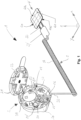
- Fig. 1 shows a first exemplary embodiment of a security arrangement 1 which is not claimed as such in a schematic perspective view.
- the security arrangement 1 comprises a security device 2, a security cable 3 and an adhesive label 4. These extend along a longitudinal direction X, a transverse direction Y and a height direction Z, which together form a Cartesian coordinate system.
- terms used in the context of this coordinate system below refer to the longitudinal direction X, left and right to the transverse direction Y and above or below to the height direction Z.
- the security device 1 has a housing 20 that is designed to be closable by a cover 21.
- the security arrangement 1 can be fixed on the housing 20 or on the cover 21 to any object, for example another object to be secured (not shown).
- the lid is provided with a closure 22 with which it can be locked on or relative to the housing 20 in a closed position (not shown).
- An interior 22 of the security device 2 can be closed with the cover 21.
- a plug receptacle 24 is arranged so that it can be secured against unauthorized access from the outside.
- Means 25 of the security device 2 for generating an alarm or at least parts thereof can also be arranged in the interior 22 protected from external access.
- a bushing 26 is formed on the housing 20, via which the security cable 3 is guided into the interior 23 in order to be electrically connected to the security device 2 at the plug receptacle 24.
- strain relief elements 27 of the securing device 2 are arranged in the interior 23, more precisely on its floor 28.
- the security cable 3 is usually designed with two wires and has a plug element 30 that is inserted into the plug receptacle 24 of the security device 2.
- a strain relief section 31 of the security cable 3 adjoins the plug element 30.
- the strain relief section 31 is held by the strain relief elements 27 of the securing device 2.
- the strain relief section 31 is guided through the strain relief elements 27 with a meandering course.
- a feedthrough section 32 of the safety cable 3 adjoins the strain relief section 31. With the feedthrough section 32, the security cable 3 is guided through the feedthrough 26 of the housing 20 into the surroundings of the housing 20.
- An extension section 33 of the security cable 3 adjoins the feedthrough section 32.
- the extension section 33 is shaped as a spiral cable.
- the transition section 34 is followed by a connection section 35, to which the adhesive label 4 is connected.
- the adhesive label 4 has a flexible base layer 40 with a top 40a and a bottom 40b.
- the top 40a points in the height direction Z.
- the bottom 40b points against the height direction Z.
- predetermined breaking lines 41 are formed in the base layer 40.
- the predetermined breaking lines 41 are designed to break if the adhesive label 4 is manipulated or a tensile force acting on the adhesive label 4 via the security cable 3 causes the predetermined breaking lines 41 to break.
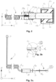
- Fig. 2 shows a schematic bottom view of the security cable 3 and the adhesive label 4, the transition section 34 being shown cut along a plane spanned in the longitudinal direction X and transverse direction Y.
- the transition section 34 is an encapsulation element designed like a housing 34a has.
- the encapsulation member 34a provides an extension retaining portion 34b and a terminal retaining portion 34c, which may be formed as passages with different cross sections.
- connection section 35 is designed, for example, as a flexible circuit board so that it can adapt to the outer contours of an object to be secured. Between the end section 33a of the extension section 33 and the beginning section 35a of the connection section 35 there is a generally two-pole connection point 36 in the transition section 34 between the extension section 33 and the connection section 35.
- connection point 36 is hermetically sealed from the environment in the encapsulation element 34a.
- the end section 33a of the extension section 33 and the beginning section 35a of the connection section 35 are connected to one another in an electrically conductive manner, for example soldered.
- a pair of connection contacts is usually used, which are described below with reference to Figs. 6 and 7 is described in more detail.
- the firm reception of the end section 33a and the beginning section 35a in the extension holding area 34b or connection holding area 34c causes a strain relief of the connection point 36 against tensile forces acting on the extension section 33 or connection section 35 along the safety cable away from the transition section 34.
- the adhesive label 4 is connected to the connection section 35 in an electrically conductive manner.
- the adhesive label 4 is provided on an adhesive or underside 40b with contact surfaces 42 which point towards the connection section 35 against the height direction Z.
- two contact surfaces 42 are provided.
- the two contact surfaces 42 are electrically conductive via a conductor track 43 connected with each other.
- the conductor track 43 is arranged at a distance from an outer edge 40c of the base layer 40.
- Fig. 3a shows the security arrangement 1 or the security cable 3 and the adhesive label 4 in a schematic side view.
- the extension section 33 of the security cable 3 has a thickness or a diameter d 33 .
- the transition section 34 has a thickness or a diameter d 34 .
- the connection section 35 has a thickness d 35 measured essentially parallel to the height direction Z.
- the thickness or diameter d 33 of the extension section 33 is, for example, between 1 and 3 mm, preferably approximately 2 mm.
- the thickness or diameter d 34 of the transition section 34 is, for example, between 6 and 10 mm, preferably approximately 8 mm.
- the thickness d 35 of the connection section 35 is, for example, 0.05 to 0.2 mm, preferably approximately 0.1 mm.
- Fig. 3b shows a detail III Fig. 3a .
- the adhesive label 4 or its base layer 40 has a thickness d 4 measured essentially parallel to the height direction Z, which is, for example, between 0.6 and 1 mm, preferably approximately 0.8 mm.
- d 4 measured essentially parallel to the height direction Z, which is, for example, between 0.6 and 1 mm, preferably approximately 0.8 mm.
- the security cable 3 or its connection section 35 is glued to the adhesive label 4 or its base layer 40 and/or the contact surfaces 42 and/or the conductor track 43.
- Fig. 4 shows the adhesive label 4 in a schematic perspective view, in particular its adhesive or underside 40b can be seen.
- the conductor track 43 is shaped so that it has a large number of deflection points 45 and straight sections 46. At the deflection points 45, the conductor track 43 changes its direction in such a way that the straight sections 46 extend essentially over the entire base layer.
- Fig. 5 shows the adhesive label 4 in a schematic bottom view.
- the conductor track 43 is arranged with its deflection points 45 and the straight sections 46 in such a way that the predetermined breaking lines 41 intersect the conductor track 43 several times. thwart.
- the predetermined breaking lines 41 intersect and form a predetermined breaking line grid 47.
- the predetermined breaking lines 41 each extend to the edges 40c of the base layer 40.
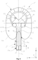
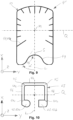
- Fig. 6 shows a claimed embodiment of a security arrangement 1 'or a security cable 3' and an adhesive label 4' in a schematic bottom view.
- the adhesive label 4 ' has a substantially oval-shaped base layer 40.
- a parabolic indentation or recess 48 in the edge 40c of the base layer 40 of the adhesive label 4' forms a transition edge section 49.
- the edge 40c runs at least in sections towards the conductor track 43 and/or the predetermined breaking lines 41 and the predetermined breaking line grid 47 formed therefrom.
- a transition angle ⁇ is formed between the transition edge section 49 and an entry direction E of the security cable 3', along which the security cable 3' is guided under the adhesive label 4'.
- the entry direction E runs essentially parallel to a longitudinal axis L of the connection section 35, which runs parallel to the longitudinal direction X.
- the longitudinal axis L runs essentially perpendicular to a transverse axis Q of the adhesive label 4 ', which in turn runs essentially parallel to the transverse direction Y.
- the predetermined breaking lines 41 of the adhesive label 4' include outer predetermined breaking lines 41a and inner predetermined breaking lines 41b.
- the outer predetermined breaking lines 41a run from the edge 40c essentially radially in the direction of a center point M of the adhesive label 4 'to or beyond the conductor track 43.
- the inner predetermined breaking lines 40b form the predetermined breaking line grid 47 by running towards or crossing one another in an interior space enclosed by the conductor track 43.
- the conductor track 43 is essentially continuously curved or has a curve, which, for example, can be viewed as horseshoe-shaped. In other words, the conductor track 43 describes an almost continuously curved curved path between the two contact surfaces 42.
- the contact surfaces 42 are designed as a first contact surface 42a and a further contact surface 42b.
- the first contact surface 42a is circular in the present exemplary embodiment.
- the further contact surface 42b has a square shape.
- the contact surfaces 42 of the adhesive label 4' are therefore coded. The coding of the contact surfaces 42 facilitates a proper electrical connection of the security cable 3 'to the adhesive label 4'.
- connection section 35 is guided with its connection section 35 under the adhesive label 4' in such a way that an outer edge section 35c of the connection section 35 is arranged in the area of the transition edge section 49.
- connection section 35 is arranged essentially centered in the initial section 35a to the indentation or recess 48, so that the longitudinal axis L in the connection section 35 runs through a vertex S of the recess 48. At the apex S, the recess 48 runs essentially parallel to the transverse axis Q.
- connection contacts 37 are used to establish an electrically conductive connection between the extension section 33 and the connection section 35 in the transition section 34 at the connection point 36.
- the connection contacts 37 are designed, for example, as solder contacts or in the form of solder surfaces.
- Two electrical connection lines 38 extend from the connection contacts 37 and are designed, for example, as flexible conductor tracks that are embedded in the connection section.
- Fig. 7 shows a schematic top view of the security cable 3 '.
- the connection lines 38 run from the connection contacts 37 to the mating contact surfaces 39 of the security cable 3 '.
- the counter-contact surfaces 39 are designed as a first counter-contact surface 39a and as a further counter-contact surface 39b.
- the first mating contact surface 39a is designed to be essentially circular to match the first contact surface 42a of the adhesive label 4'.
- the further mating contact surface 39b is designed to be essentially square to match the further contact surface 42b.
- the contact and mating contact surfaces 42, 39 can be shaped according to the respective requirements in order to achieve a desired assignment or coding.
- the mating contact surfaces 39 are arranged in a head section 35b of the security cable 3 '.
- the connecting lines 38 each curve away from the longitudinal axis L towards the mating contact surfaces 39.
- Fig. 8 shows the adhesive label 4 'in a schematic bottom view.
- the head section 35b of the security cable 3' is fixed to the object using the adhesive label 4'.
- the coded contact surfaces 42 and mating contact surfaces 39 help to properly stick the adhesive label 4 'over the head section 35b in such a way that an electrical contact between contact surfaces 42 and mating contact surfaces 39 that meets the respective requirements is established.
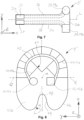
- Fig. 9 shows a further embodiment of an adhesive label 4" according to the invention in a schematic top view.
- the adhesive label 4" is designed to be compatible with the security cable 3'.
- the adhesive label 4 " only has external predetermined breaking lines 41a, which are radial to the center point M run there.
- the indentation or recess 48 of the adhesive label 4" is designed in such a way that the respective transition edge section 49 each runs towards the longitudinal axis L at an entry angle ⁇ '.
- the entry angle ⁇ ' is larger than the entry angle ⁇ in the case of the adhesive label 4'. and can be approximately 45°, for example.
- Fig. 10 shows the contact surfaces 42 and the conductor track 43 of the adhesive label 4".
- the conductor track 43 in turn comprises deflection points 45 and straight sections 46, which together enclose an interior space.
- a contact point 42a of the two contact points 42 is in turn designed to be circular or round at least in sections, whereas the The other contact point 42b of the two contact points 42 is designed to be at least partially angular or rectangular or square.
- a coding of the contact surfaces 42 is therefore also implemented in the adhesive label 4".
- Contact points 42 and conductor track 43 can be in the in Fig. 10 shown form can be cut or punched in one piece from a metal, for example from copper or a copper strip, in order to be glued to the support section 40, for example.
- Contact points 42 and/or conductor track 43 are provided with predetermined breaking points 41c. At the predetermined breaking points 41c, it is easier to break open the contact points 42 or the conductor track 43 if an object provided with the adhesive label 4" is exposed to an attempt at manipulation or theft.
- Fig. 11 shows a further exemplary embodiment according to the invention of a security arrangement 1" or a security cable 3" and an adhesive label 4′′′ in a schematic bottom view.
- the exemplary embodiment of the security cable 3 "has strain relief sections 35d in its connection section 35, which extend laterally away from the edge section 35c on both sides of the connection section 35.
- the strain relief sections 35d are arranged in an area of the adhesive label 4 'that is free of predetermined breaking lines 41.
- the tongue-like strain relief sections 35d expand the adhesive area 44 to the side of the connection section 35 transversely to the longitudinal axis L and help forces, in particular tensile forces, acting on the connection section 35 parallel to the transverse direction Y from the direction of the initial section 35a, from the securing cable 3" to the adhesive label 4′′′ transferred without them becoming detached from one another or shifting relative to one another along the transverse direction Y.
- the strain relief sections 35d can thus compensate for the stability of the connection between the security cable 3′′ and the adhesive label 4′′′ along the longitudinal direction X and transverse direction Y. In other words, the strain relief section 35d contributes to ensuring that the connection between the security cable 3′′ and the adhesive label 4′′′ has essentially the same stability in the longitudinal direction X and transverse direction Y.
- the adhesive label 4′′′ measured parallel to the longitudinal axis L, is shorter than the adhesive label 4′′ described above.
- At least some of the predetermined breaking lines 41 of the adhesive label 4′′′ are dimensioned such that they extend from the edge 40c to over the conductor track 43.
- the predetermined breaking lines 41 coincide with predetermined breaking points 41c attached to the conductor track 43.
- predetermined breaking lines 41 and/or predetermined breaking points 41c intersect the conductor track 43 at least partially transversely to the course of the conductor track 43.
- Fig. 12 shows a schematic top view of the safety cable 3".
- the strain relief sections 35d are arranged in the longitudinal direction X in front of the head section 35b and extend from the edge section on both sides of the connection section 35 35c in or against the transverse direction Y.
- the strain relief sections 35d thus form a hammerhead-like shape. Similar to the head section 35b, transitions between the strain relief section 35d and the edge section 35c are rounded in order to prevent the connection section 35 from tearing at the transitions.
- Fig. 12 shown how in the transition section 34 of the security cable 3" the initial section 35a of the connection section 35 is received in the transparently shown encapsulation member 34a and connected to the extension section 33 of the security cable 3".
- the end section 33a of the security cable 3" is guided in the longitudinal direction
- the electrical conductors 33c are each electrically conductively connected to one of the two connection contacts 37 at the connection points 36.
- the connection can be formed, for example, by soldering or the like.
- the extension section 33 is provided with a strain relief element 33d and the connection section 35 is provided with an upper fixing element 35e. Strain relief element 33d and upper fixing element 35e are accommodated in a form-fitting manner in the encapsulation element 34a.
- Fig. 13 shows the transition section 34 of the security cable 3", in particular parts of the security cable 3" adjacent to the connection points 36, with the encapsulation element 34a omitted, in a schematic perspective view.
- the strain relief element 33d is placed over the casing 33b at the extension section 33 and can surround an end of the casing 33b pointing in the direction of the free electrical conductors 33c or be essentially flush with it.
- the strain relief element 33d can be connected both to the casing 33b and to the electrical conductors 33c or one around them around at least sections remaining second individual casing be positively, non-positively, cohesively and / or connected by gluing.
- the cuboid upper fixing element 35e is arranged on the top of the connection section 35 in the immediate vicinity of the connection contacts 37 and can be fastened positively, non-positively, cohesively and/or by gluing.
- a lower fixing element 35f is arranged, which is also cuboid-shaped and can be fastened positively, non-positively, cohesively and/or by gluing.
- the lower fixing element 35f covers an area of the underside of the connection section 35, opposite which the upper fixing element 35e and the connecting contacts 37 are arranged on the top side.
- connection points 36 are protected from mechanical stresses, in particular bending, and on the other hand a three-dimensional outer contour is provided for positively holding the end section 35a of the connection section 35 in the encapsulation element 34a.
- Fig. 14 shows a schematic cross-sectional view of the transition section 34 of the safety cable 3" in the area of the connection points 36.
- the encapsulation element 34a surrounds the end section 33a, the strain relief element 33d attached thereto as well as the beginning section 35a and the fixing elements 35e, 35f attached therein.
- the encapsulation element 34a can be around the Fuse cable 3" can be crimped and/or thermoplastically shaped or designed as a type of crimp sleeve.
- the encapsulation member 34a forms a cavity-like interior 34d, in which the electrical conductors 33c are housed protected from harmful environmental influences and mechanical influences.
- the strain relief element 33d is held in a form-fitting manner in the extension holding area 34b of the encapsulation member 34a.
- form-fitting elements 34e in the form of projections, shoulders and/or the like are formed on the extension holding area 34b, which limit a range of movement for the strain relief elements 33d at least in and against the longitudinal direction X.
- the extension holding area 34b is designed to be complementary to the sleeve-shaped strain relief element 33d, so that the strain relief element 33d is received as tightly as possible in the extension holding area 34b.
- connection holding area 34c The fixing elements 35e, 35f are held in a form-fitting manner in the connection holding area 34c of the encapsulation element 34a.
- the connection holding area 34c is also provided with positive locking elements 34e in the form of projections, shoulders and/or the like, which limit a range of movement for the fixing elements 35e, 35f at least in and against the longitudinal direction X.
- the connection holding area 34c is therefore designed to be complementary to the fixing elements 35e, 35f, so that they are accommodated as tightly as possible in the connection holding area 34c.
- a security arrangement 1, 1', 1" according to the invention can therefore comprise any number of security devices 2, security cables 3, 3', 3" and adhesive labels 4, 4', 4", 4" in accordance with the respective requirements can be designed and shaped to secure an object from manipulation and/or theft.
- the safety device 2 can be equipped with housings 20, covers 21, closures 22, interior spaces 23, plug receptacle 24, means 25 for generating an alarm, bushings 26, strain relief elements according to the respective requirements 27 and/or bases 28 may be provided in order to be able to connect at least one security cable 3, 3', 3" to the security device 2 in order to secure an object from manipulation and/or theft.
- the security device 2 does not necessarily have to be as shown here be designed, but can be constructed in any other way in order to electronically monitor the condition of the security cable 3, 3 ', 3 "or adhesive label 4, 4 ', 4", 4 "as an alarm device or security system.
- the safety cable 3, 3', 3" can have plug elements 30, strain relief sections 31, feedthrough sections 32, extension sections 33, end sections 33a, sheaths 33b, electrical conductors 33c, strain relief elements 33d, transition sections 34, encapsulation elements 34a, extension holding areas 34b, connection holding areas 34c according to the respective requirements , Interiors 34d, shape elements 34E, connection sections 35, initial sections 35a, head section 35b, edge sections 35c, strain relief sections 35d, upper fixation elements 35e, lower fixation 36, connection contacts 38, connection lines 38, counter -contact surfaces 39a and/or other counter areas 39b in order to electrically conductively connect the security device 2 to adhesive labels 4, 4', 4" in accordance with the respective requirements and thereby cooperate in a suitable manner with the adhesive labels 4, 4', 4" to trigger an alarm through the security device 2 in the event of manipulation or theft of an object to be secured.
- the adhesive label 4, 4', 4" can have supporting layers 40, top sides 40a, undersides or adhesive sides 40b, edges 40c, predetermined breaking lines 41, outer predetermined breaking lines 41a, inner predetermined breaking lines 41b, predetermined breaking points 41c, contact surfaces 42, first contact surfaces 42a according to the respective requirements , further contact surfaces 42b, conductor tracks 43, adhesive areas 44, deflection points 45, straight sections 46, predetermined breaking line grid 47, recesses 48 and / or transition edge sections 49 in order to cooperate with the safety cable 3, 3 'to trigger a To cause an alarm through the security device 2 in the event of manipulation or theft of an object to be secured.
Landscapes
- Physics & Mathematics (AREA)
- General Physics & Mathematics (AREA)
- Burglar Alarm Systems (AREA)
Claims (15)
- Étiquette adhésive (4, 4', 4'', 4''') pour la fixation d'un câble de sécurité (3, 3', 3'') d'un dispositif de sécurité électronique (2) sur un objet à protéger contre le vol et/ou la manipulation, avec une couche de support flexible (40) qui forme une face adhésive (40b) par laquelle l'étiquette adhésive (4, 4', 4'', 4''') doit être collée sur l'objet, et comprenant au moins une piste électriquement conductrice (43), qui est reliée de manière électriquement conductrice à au moins une surface de contact (42) située dans le côté adhésif (40b) pour la mise en contact électrique du câble de sécurité (3, 3', 3''), et l'étiquette adhésive (4, 4', 4'', 4''') présentant au moins une autre surface de contact (42, 42a) reliée à ladite au moins une piste conductrice (43), et en ce que ladite au moins une surface de contact et ladite au moins une autre surface de contact (42, 42b) présentent des contours différents pour le codage.
- Étiquette adhésive (4, 4', 4", 4‴) selon la revendication 1, caractérisée en ce que le côté adhésif (40b) et/ou ladite au moins une surface de contact (42) sont pourvus, au moins par sections, d'une couche adhésive conduisant l'électricité de manière isotrope et/ou anisotrope, dont la conductivité électrique est plus grande dans une direction de contact s'étendant perpendiculairement au côté adhésif (40b) que dans un plan de fixation de l'étiquette adhésive (4, 4', 4'', 4''') passant par la couche de support (40).
- Étiquette adhésive (4, 4', 4", 4‴) selon la revendication 1 ou 2, caractérisée en ce que ladite au moins une piste électriquement conductrice (43) et/ou ladite au moins une surface de contact (42) s'incurvent au moins par sections à partir de la couche de support (40) .
- Étiquette adhésive (4, 4', 4", 4‴) selon au moins l'une des revendications 1 à 3, caractérisée en ce que ladite au moins une piste conductrice électrique (43) et/ou ladite au moins une surface de contact (42) sont noyées au moins par sections dans la couche de support (40) .
- Étiquette adhésive (4, 4', 4", 4‴) selon au moins l'une des revendications 1 à 4, caractérisée en ce que la couche de support (40) présente au moins une ligne de rupture (41) qui croise ladite au moins une piste conductrice (43).
- Étiquette adhésive (4, 4', 4", 4‴) selon au moins l'une des revendications 1 à 5, caractérisée en ce que la couche de support (40) présente une grille de lignes de rupture (47) à travers laquelle s'étend au moins par sections ladite au moins une piste conductrice (43) .
- Étiquette adhésive (4, 4', 4", 4‴) selon la revendication 5 ou 6, caractérisée en ce que ladite au moins une ligne de rupture (41) ou la grille de lignes de rupture (47) s'étend ou s'étendent jusqu'à un bord extérieur (40c) de la couche de support (40).
- Étiquette adhésive (4, 4', 4", 4‴) selon au moins l'une des revendications 1 à 7, caractérisée en ce que ladite au moins une piste conductrice (43) est pourvue d'au moins une ligne de rupture (41c).
- Étiquette adhésive (4, 4', 4", 4‴) selon au moins l'une des revendications 1 à 8, caractérisée en ce que, sur la couche de support (40), une zone d'entrée de câble, au niveau de laquelle le câble de sécurité (3, 3', 3'') passe sous l'étiquette adhésive (4, 4', 4", 4‴) depuis l'extérieur, est formée avec une partie en retrait (48) qui comprend au moins une portion de bord de transition (49) qui s'étend au moins par sections en direction de ladite au moins une piste conductrice (43).
- Étiquette adhésive (4, 4', 4'', 4''') selon la revendication 9, caractérisée en ce que ladite au moins une section de bord de transition (49) s'étend au moins par sections selon un angle de transition (α) de moins de 45°, de préférence de moins de 30°, vers une direction d'entrée (E) dans laquelle le câble de sécurité (3, 3', 3'') doit être guidé sous l'étiquette adhésive (4, 4', 4", 4‴).
- Étiquette adhésive (4, 4', 4'', 4''') selon au moins une des revendications 1 à 10, caractérisée en ce que ladite au moins une piste conductrice (43) présente un tracé de forme arquée.
- Étiquette adhésive (4, 4', 4'', 4''') selon au moins une des revendications 1 à 11, caractérisée en ce que ladite au moins une piste conductrice (43) est déviée au niveau d'au moins un coude ou d'au moins une courbe.
- Câble de sécurité (3, 3', 3'') pour un dispositif de sécurité électronique (2) destiné à protéger un objet contre le vol et/ou la manipulation, comprenant une contre-surface de contact (39) qui est configurée de manière complémentaire à au moins une surface de contact (42) d'une étiquette adhésive (4, 4', 4'', 4''') selon au moins l'une des revendications 1 à 12.
- Dispositif de sécurité (1) pour protéger un objet contre le vol et/ou la manipulation, avec au moins une étiquette adhésive (4, 4', 4'', 4‴) selon au moins l'une des revendications 1 à 12, comprenant au moins un câble de sécurité (3, 3', 3'') selon la revendication 13 et comprenant au moins un dispositif de sécurité (2) qui est configuré pour surveiller électriquement ladite au moins une piste conductrice (43).
- Procédé pour protéger un objet contre le vol et/ou la manipulation, dans lequel une section de raccordement (35) d'un câble de sécurité flexible (3, 3', 3'') est fixée sur l'objet au moyen d'une étiquette adhésive flexible (4, 4', 4", 4‴) selon au moins l'une des revendications 1 à 12, et dans lequel, pendant la fixation, une contre-surface de contact (39) selon la revendication 13 est mise en contact électriquement conducteur avec au moins une surface de contact (42) de l'étiquette adhésive (4, 4', 4'', 4''') sur la section de raccordement (35).
Applications Claiming Priority (2)
| Application Number | Priority Date | Filing Date | Title |
|---|---|---|---|
| CH00669/16A CH712486A1 (de) | 2016-05-24 | 2016-05-24 | Klebeetikett, Sicherungskabel, Sicherungsanordnung und Verfahren zum Sichern von Objekten. |
| PCT/EP2017/062663 WO2017202986A1 (fr) | 2016-05-24 | 2017-05-24 | Étiquette adhésive, câble de protection, ensemble de protection et procédé de protection d'objets |
Publications (3)
| Publication Number | Publication Date |
|---|---|
| EP3465645A1 EP3465645A1 (fr) | 2019-04-10 |
| EP3465645B1 true EP3465645B1 (fr) | 2023-10-11 |
| EP3465645C0 EP3465645C0 (fr) | 2023-10-11 |
Family
ID=56119253
Family Applications (1)
| Application Number | Title | Priority Date | Filing Date |
|---|---|---|---|
| EP17727545.0A Active EP3465645B1 (fr) | 2016-05-24 | 2017-05-24 | Étiquette adhésive, câble de protection, ensemble de protection et procédé de protection d'objets |
Country Status (3)
| Country | Link |
|---|---|
| EP (1) | EP3465645B1 (fr) |
| CH (1) | CH712486A1 (fr) |
| WO (1) | WO2017202986A1 (fr) |
Families Citing this family (1)
| Publication number | Priority date | Publication date | Assignee | Title |
|---|---|---|---|---|
| DE102020211267A1 (de) | 2020-09-08 | 2022-03-10 | Rapitag Gmbh | Verschlusssicherung |
Family Cites Families (3)
| Publication number | Priority date | Publication date | Assignee | Title |
|---|---|---|---|---|
| US5910768A (en) * | 1995-04-04 | 1999-06-08 | Ott; Reinhold | Anti-theft device |
| CH698863B1 (de) | 2006-07-19 | 2009-11-30 | Pataco Ag Ind Und Unterhaltung | Sicherungsvorrichtung |
| CH703299A1 (de) | 2010-06-07 | 2011-12-15 | Pataco Ag Ind Und Unterhaltungselektronik | Sicherungsvorrichtung für Objekte. |
-
2016
- 2016-05-24 CH CH00669/16A patent/CH712486A1/de not_active Application Discontinuation
-
2017
- 2017-05-24 EP EP17727545.0A patent/EP3465645B1/fr active Active
- 2017-05-24 WO PCT/EP2017/062663 patent/WO2017202986A1/fr not_active Ceased
Also Published As
| Publication number | Publication date |
|---|---|
| EP3465645C0 (fr) | 2023-10-11 |
| CH712486A1 (de) | 2017-11-30 |
| WO2017202986A1 (fr) | 2017-11-30 |
| EP3465645A1 (fr) | 2019-04-10 |
Similar Documents
| Publication | Publication Date | Title |
|---|---|---|
| EP2883273B1 (fr) | Boîtier de connecteur enfichable équipé d'un transpondeur rfid | |
| DE60116307T2 (de) | Diebstahlsichere halterung für demonstrationsartikel | |
| EP2434582B1 (fr) | Borne de connexion | |
| AT398677B (de) | Schutzmodul für elektromagnete von schaltvorrichtungen | |
| DE2746093A1 (de) | Stroemungsmittel-leitungssystem | |
| DE102014014913B3 (de) | Plombe zur Sicherung von Waren | |
| EP1262618A2 (fr) | Dispositif de sécurité de biens | |
| DE202011000613U1 (de) | Vorrichtung zur Übertragung von elektrischer Energie und/oder elektrischen Signalen von einer feststehenden Wand auf einen an der Wand befestigten Flügel | |
| EP3465645B1 (fr) | Étiquette adhésive, câble de protection, ensemble de protection et procédé de protection d'objets | |
| DE3705885A1 (de) | Schliesse fuer elektrische ladung ableitende baender od. dgl. | |
| DE9105960U1 (de) | Schutzvorrichtung für Schaltungsteile und/oder Daten in einem Gerät zur Authentifikation und Betragsbestätigung | |
| EP1394069A1 (fr) | Emballage de vente pour batteries | |
| DE19548073C1 (de) | IC-Karte | |
| EP3278638B1 (fr) | Appareil électronique | |
| EP2976269A1 (fr) | Canette pour boissons | |
| DE102009028333B4 (de) | Steckverbindersystem mit Möglichkeit zum Erkennen einer Falschsteckung durch Kurzschlussverbindung | |
| WO2004098954A2 (fr) | Systeme de connexion electrique male-femelle | |
| DE202023100840U1 (de) | Elektronische Warenauszeichnungseinheit zur Anbringung an einem bügelförmigen Warenträger | |
| DE102016100218B3 (de) | Vorrichtung und Verfahren zur Verbindung mindestens zweier elektrischer Leiter | |
| DE10020761B4 (de) | Folienleiter sowie Verfahren zur Herstellung eines Folienleiters | |
| DE8905481U1 (de) | Vorrichtung zur Sicherung von Gegenständen gegen unbefugtes Mitnehmen oder Entnehmen | |
| DE29817464U1 (de) | Anschlußset für ein elektrisches Gerät | |
| DE9217006U1 (de) | Antenne für schnurlose Telefone | |
| DE19934403C1 (de) | Elektrische Kontaktanordnung | |
| DE202007013449U1 (de) | Warensicherungsvorrichtung zur Sicherung von Waren und Zubehörteilen gegen Diebstahl |
Legal Events
| Date | Code | Title | Description |
|---|---|---|---|
| STAA | Information on the status of an ep patent application or granted ep patent |
Free format text: STATUS: UNKNOWN |
|
| STAA | Information on the status of an ep patent application or granted ep patent |
Free format text: STATUS: THE INTERNATIONAL PUBLICATION HAS BEEN MADE |
|
| PUAI | Public reference made under article 153(3) epc to a published international application that has entered the european phase |
Free format text: ORIGINAL CODE: 0009012 |
|
| STAA | Information on the status of an ep patent application or granted ep patent |
Free format text: STATUS: REQUEST FOR EXAMINATION WAS MADE |
|
| 17P | Request for examination filed |
Effective date: 20181221 |
|
| AK | Designated contracting states |
Kind code of ref document: A1 Designated state(s): AL AT BE BG CH CY CZ DE DK EE ES FI FR GB GR HR HU IE IS IT LI LT LU LV MC MK MT NL NO PL PT RO RS SE SI SK SM TR |
|
| AX | Request for extension of the european patent |
Extension state: BA ME |
|
| DAV | Request for validation of the european patent (deleted) | ||
| DAX | Request for extension of the european patent (deleted) | ||
| STAA | Information on the status of an ep patent application or granted ep patent |
Free format text: STATUS: EXAMINATION IS IN PROGRESS |
|
| 17Q | First examination report despatched |
Effective date: 20210420 |
|
| P01 | Opt-out of the competence of the unified patent court (upc) registered |
Effective date: 20230512 |
|
| GRAP | Despatch of communication of intention to grant a patent |
Free format text: ORIGINAL CODE: EPIDOSNIGR1 |
|
| STAA | Information on the status of an ep patent application or granted ep patent |
Free format text: STATUS: GRANT OF PATENT IS INTENDED |
|
| INTG | Intention to grant announced |
Effective date: 20230627 |
|
| GRAS | Grant fee paid |
Free format text: ORIGINAL CODE: EPIDOSNIGR3 |
|
| GRAA | (expected) grant |
Free format text: ORIGINAL CODE: 0009210 |
|
| STAA | Information on the status of an ep patent application or granted ep patent |
Free format text: STATUS: THE PATENT HAS BEEN GRANTED |
|
| AK | Designated contracting states |
Kind code of ref document: B1 Designated state(s): AL AT BE BG CH CY CZ DE DK EE ES FI FR GB GR HR HU IE IS IT LI LT LU LV MC MK MT NL NO PL PT RO RS SE SI SK SM TR |
|
| REG | Reference to a national code |
Ref country code: GB Ref legal event code: FG4D Free format text: NOT ENGLISH |
|
| REG | Reference to a national code |
Ref country code: CH Ref legal event code: EP |
|
| REG | Reference to a national code |
Ref country code: DE Ref legal event code: R096 Ref document number: 502017015477 Country of ref document: DE |
|
| REG | Reference to a national code |
Ref country code: IE Ref legal event code: FG4D Free format text: LANGUAGE OF EP DOCUMENT: GERMAN |
|
| U01 | Request for unitary effect filed |
Effective date: 20231016 |
|
| U07 | Unitary effect registered |
Designated state(s): AT BE BG DE DK EE FI FR IT LT LU LV MT NL PT SE SI Effective date: 20231024 |
|
| P04 | Withdrawal of opt-out of the competence of the unified patent court (upc) registered |
Effective date: 20231020 |
|
| PG25 | Lapsed in a contracting state [announced via postgrant information from national office to epo] |
Ref country code: GR Free format text: LAPSE BECAUSE OF FAILURE TO SUBMIT A TRANSLATION OF THE DESCRIPTION OR TO PAY THE FEE WITHIN THE PRESCRIBED TIME-LIMIT Effective date: 20240112 |
|
| PG25 | Lapsed in a contracting state [announced via postgrant information from national office to epo] |
Ref country code: IS Free format text: LAPSE BECAUSE OF FAILURE TO SUBMIT A TRANSLATION OF THE DESCRIPTION OR TO PAY THE FEE WITHIN THE PRESCRIBED TIME-LIMIT Effective date: 20240211 |
|
| PG25 | Lapsed in a contracting state [announced via postgrant information from national office to epo] |
Ref country code: ES Free format text: LAPSE BECAUSE OF FAILURE TO SUBMIT A TRANSLATION OF THE DESCRIPTION OR TO PAY THE FEE WITHIN THE PRESCRIBED TIME-LIMIT Effective date: 20231011 |
|
| PG25 | Lapsed in a contracting state [announced via postgrant information from national office to epo] |
Ref country code: IS Free format text: LAPSE BECAUSE OF FAILURE TO SUBMIT A TRANSLATION OF THE DESCRIPTION OR TO PAY THE FEE WITHIN THE PRESCRIBED TIME-LIMIT Effective date: 20240211 Ref country code: GR Free format text: LAPSE BECAUSE OF FAILURE TO SUBMIT A TRANSLATION OF THE DESCRIPTION OR TO PAY THE FEE WITHIN THE PRESCRIBED TIME-LIMIT Effective date: 20240112 Ref country code: ES Free format text: LAPSE BECAUSE OF FAILURE TO SUBMIT A TRANSLATION OF THE DESCRIPTION OR TO PAY THE FEE WITHIN THE PRESCRIBED TIME-LIMIT Effective date: 20231011 |
|
| PG25 | Lapsed in a contracting state [announced via postgrant information from national office to epo] |
Ref country code: RS Free format text: LAPSE BECAUSE OF FAILURE TO SUBMIT A TRANSLATION OF THE DESCRIPTION OR TO PAY THE FEE WITHIN THE PRESCRIBED TIME-LIMIT Effective date: 20231011 Ref country code: PL Free format text: LAPSE BECAUSE OF FAILURE TO SUBMIT A TRANSLATION OF THE DESCRIPTION OR TO PAY THE FEE WITHIN THE PRESCRIBED TIME-LIMIT Effective date: 20231011 Ref country code: NO Free format text: LAPSE BECAUSE OF FAILURE TO SUBMIT A TRANSLATION OF THE DESCRIPTION OR TO PAY THE FEE WITHIN THE PRESCRIBED TIME-LIMIT Effective date: 20240111 Ref country code: HR Free format text: LAPSE BECAUSE OF FAILURE TO SUBMIT A TRANSLATION OF THE DESCRIPTION OR TO PAY THE FEE WITHIN THE PRESCRIBED TIME-LIMIT Effective date: 20231011 |
|
| REG | Reference to a national code |
Ref country code: DE Ref legal event code: R097 Ref document number: 502017015477 Country of ref document: DE |
|
| PG25 | Lapsed in a contracting state [announced via postgrant information from national office to epo] |
Ref country code: CZ Free format text: LAPSE BECAUSE OF FAILURE TO SUBMIT A TRANSLATION OF THE DESCRIPTION OR TO PAY THE FEE WITHIN THE PRESCRIBED TIME-LIMIT Effective date: 20231011 |
|
| PG25 | Lapsed in a contracting state [announced via postgrant information from national office to epo] |
Ref country code: SK Free format text: LAPSE BECAUSE OF FAILURE TO SUBMIT A TRANSLATION OF THE DESCRIPTION OR TO PAY THE FEE WITHIN THE PRESCRIBED TIME-LIMIT Effective date: 20231011 |
|
| PG25 | Lapsed in a contracting state [announced via postgrant information from national office to epo] |
Ref country code: SM Free format text: LAPSE BECAUSE OF FAILURE TO SUBMIT A TRANSLATION OF THE DESCRIPTION OR TO PAY THE FEE WITHIN THE PRESCRIBED TIME-LIMIT Effective date: 20231011 Ref country code: SK Free format text: LAPSE BECAUSE OF FAILURE TO SUBMIT A TRANSLATION OF THE DESCRIPTION OR TO PAY THE FEE WITHIN THE PRESCRIBED TIME-LIMIT Effective date: 20231011 Ref country code: RO Free format text: LAPSE BECAUSE OF FAILURE TO SUBMIT A TRANSLATION OF THE DESCRIPTION OR TO PAY THE FEE WITHIN THE PRESCRIBED TIME-LIMIT Effective date: 20231011 Ref country code: CZ Free format text: LAPSE BECAUSE OF FAILURE TO SUBMIT A TRANSLATION OF THE DESCRIPTION OR TO PAY THE FEE WITHIN THE PRESCRIBED TIME-LIMIT Effective date: 20231011 |
|
| PLBE | No opposition filed within time limit |
Free format text: ORIGINAL CODE: 0009261 |
|
| STAA | Information on the status of an ep patent application or granted ep patent |
Free format text: STATUS: NO OPPOSITION FILED WITHIN TIME LIMIT |
|
| 26N | No opposition filed |
Effective date: 20240712 |
|
| REG | Reference to a national code |
Ref country code: CH Ref legal event code: PL |
|
| P05 | Withdrawal of opt-out of the competence of the unified patent court (upc) changed |
Free format text: CASE NUMBER: APP_581457/2023 Effective date: 20231024 |
|
| PG25 | Lapsed in a contracting state [announced via postgrant information from national office to epo] |
Ref country code: MC Free format text: LAPSE BECAUSE OF FAILURE TO SUBMIT A TRANSLATION OF THE DESCRIPTION OR TO PAY THE FEE WITHIN THE PRESCRIBED TIME-LIMIT Effective date: 20231011 |
|
| U90 | Renewal fees not paid: noting of loss of rights |
Free format text: RENEWAL FEE NOT PAID FOR YEAR 08 Effective date: 20241217 |
|
| GBPC | Gb: european patent ceased through non-payment of renewal fee |
Effective date: 20240524 |
|
| PG25 | Lapsed in a contracting state [announced via postgrant information from national office to epo] |
Ref country code: MC Free format text: LAPSE BECAUSE OF FAILURE TO SUBMIT A TRANSLATION OF THE DESCRIPTION OR TO PAY THE FEE WITHIN THE PRESCRIBED TIME-LIMIT Effective date: 20231011 Ref country code: CH Free format text: LAPSE BECAUSE OF NON-PAYMENT OF DUE FEES Effective date: 20240531 |
|
| U93 | Unitary patent lapsed |
Free format text: RENEWAL FEE NOT PAID Effective date: 20240531 |
|
| PG25 | Lapsed in a contracting state [announced via postgrant information from national office to epo] |
Ref country code: IE Free format text: LAPSE BECAUSE OF NON-PAYMENT OF DUE FEES Effective date: 20240524 |
|
| PG25 | Lapsed in a contracting state [announced via postgrant information from national office to epo] |
Ref country code: GB Free format text: LAPSE BECAUSE OF NON-PAYMENT OF DUE FEES Effective date: 20240524 |
|
| PG25 | Lapsed in a contracting state [announced via postgrant information from national office to epo] |
Ref country code: CY Free format text: LAPSE BECAUSE OF FAILURE TO SUBMIT A TRANSLATION OF THE DESCRIPTION OR TO PAY THE FEE WITHIN THE PRESCRIBED TIME-LIMIT; INVALID AB INITIO Effective date: 20170524 |
|
| PG25 | Lapsed in a contracting state [announced via postgrant information from national office to epo] |
Ref country code: HU Free format text: LAPSE BECAUSE OF FAILURE TO SUBMIT A TRANSLATION OF THE DESCRIPTION OR TO PAY THE FEE WITHIN THE PRESCRIBED TIME-LIMIT; INVALID AB INITIO Effective date: 20170524 |