EP3465645B1 - Adhesive label, security cable, security assembly and method for securing objects - Google Patents
Adhesive label, security cable, security assembly and method for securing objects Download PDFInfo
- Publication number
- EP3465645B1 EP3465645B1 EP17727545.0A EP17727545A EP3465645B1 EP 3465645 B1 EP3465645 B1 EP 3465645B1 EP 17727545 A EP17727545 A EP 17727545A EP 3465645 B1 EP3465645 B1 EP 3465645B1
- Authority
- EP
- European Patent Office
- Prior art keywords
- adhesive label
- conductor track
- security
- adhesive
- contact surface
- Prior art date
- Legal status (The legal status is an assumption and is not a legal conclusion. Google has not performed a legal analysis and makes no representation as to the accuracy of the status listed.)
- Active
Links
- 239000000853 adhesive Substances 0.000 title claims description 178
- 230000001070 adhesive effect Effects 0.000 title claims description 178
- 238000000034 method Methods 0.000 title claims description 7
- 239000004020 conductor Substances 0.000 claims description 81
- 230000007704 transition Effects 0.000 claims description 38
- 239000010410 layer Substances 0.000 claims description 35
- 239000012790 adhesive layer Substances 0.000 claims description 15
- 230000000295 complement effect Effects 0.000 claims description 3
- 230000013011 mating Effects 0.000 description 15
- 238000005538 encapsulation Methods 0.000 description 14
- 238000004806 packaging method and process Methods 0.000 description 9
- 238000007373 indentation Methods 0.000 description 7
- RYGMFSIKBFXOCR-UHFFFAOYSA-N Copper Chemical compound [Cu] RYGMFSIKBFXOCR-UHFFFAOYSA-N 0.000 description 6
- 229910052802 copper Inorganic materials 0.000 description 6
- 239000010949 copper Substances 0.000 description 6
- 238000004026 adhesive bonding Methods 0.000 description 3
- 239000002390 adhesive tape Substances 0.000 description 3
- 238000005520 cutting process Methods 0.000 description 3
- 238000012544 monitoring process Methods 0.000 description 3
- 238000005452 bending Methods 0.000 description 2
- 238000004519 manufacturing process Methods 0.000 description 2
- 230000003287 optical effect Effects 0.000 description 2
- 229910000679 solder Inorganic materials 0.000 description 2
- 241000699670 Mus sp. Species 0.000 description 1
- 230000001154 acute effect Effects 0.000 description 1
- 238000013475 authorization Methods 0.000 description 1
- 238000011109 contamination Methods 0.000 description 1
- 230000001419 dependent effect Effects 0.000 description 1
- 238000013461 design Methods 0.000 description 1
- 230000007613 environmental effect Effects 0.000 description 1
- 239000004744 fabric Substances 0.000 description 1
- 239000000463 material Substances 0.000 description 1
- 239000002184 metal Substances 0.000 description 1
- 229910052751 metal Inorganic materials 0.000 description 1
- 210000000056 organ Anatomy 0.000 description 1
- 238000012536 packaging technology Methods 0.000 description 1
- 238000004080 punching Methods 0.000 description 1
- 238000005476 soldering Methods 0.000 description 1
- 230000002123 temporal effect Effects 0.000 description 1
- 238000012546 transfer Methods 0.000 description 1
- 238000003466 welding Methods 0.000 description 1
- 238000004804 winding Methods 0.000 description 1
Images


Classifications
-
- G—PHYSICS
- G08—SIGNALLING
- G08B—SIGNALLING OR CALLING SYSTEMS; ORDER TELEGRAPHS; ALARM SYSTEMS
- G08B13/00—Burglar, theft or intruder alarms
- G08B13/02—Mechanical actuation
- G08B13/14—Mechanical actuation by lifting or attempted removal of hand-portable articles
- G08B13/1445—Mechanical actuation by lifting or attempted removal of hand-portable articles with detection of interference with a cable tethering an article, e.g. alarm activated by detecting detachment of article, breaking or stretching of cable
- G08B13/1454—Circuit arrangements thereof
Definitions
- the present invention relates to an adhesive label for attaching a security cable of an electronic security device to an object to be secured against theft and/or manipulation.
- the invention further relates to a security cable for an electronic security device for securing an object against theft and/or manipulation.
- the invention further relates to a security arrangement for securing an object against theft and/or manipulation.
- the invention relates to a method for securing an object against theft and/or manipulation.
- tags are attached to the goods to be secured, which can be detected by the system's electronics via antennas usually located at the exit of the shops.
- the tags are, for example, electrical resonant circuits with resonance frequencies in the radio frequency range (a few MHz).
- the tags In order for the security to work, the tags must be connected to the goods to be secured in such a way that they cannot be easily and unnoticed by unauthorized persons. In the case of clothing, for example, this is achieved by inserting a needle through the fabric and securing the tip of the needle with a lock, which requires special equipment to remove.
- the tag is housed in the needle head (hard tag) or in the lock. Small items can be stored in clear, lockable containers that contain the tag inside.
- tags in housings that are attached to the packaging with straps are used.
- the bands are electrically conductive and are monitored by electronics for electrical continuity. If the straps are cut to allow the security device to be removed without authorization, the electronics generate an alarm.
- a mechanism is housed in the housings for winding and tensioning the straps. Since this cannot be as voluminous as desired, the band's adjustment range for adjusting its length is limited, which limits its application to packaging in a certain size range.
- a securing device is proposed for objects which are strapped with simple, electrically non-conductive straps, as are standardly used in packaging technology.
- the straps are made of sturdy plastic and are stretched around the packaging using a tensioning device, with their ends being connected to form a closed loop using locking sleeves or by welding.
- the security device has two housing shells which can be locked together and into engagement with the straps.
- the device further comprises two cylindrical, rotatably mounted and each provided with a slot for the bands Clamping elements that are pretensioned by tension springs. When attaching the securing device to the object, the straps are guided through the slots in the tensioning elements.
- such tapes can also prevent the packaging from being opened.
- the contents of the packaging are often not checked when purchasing. When you unpack it at home, it may turn out that the contents do not meet expectations. This may be caused by the packaging being opened during transport, in the warehouse or in the sales outlet and the goods contained therein being removed and possibly exchanged for another, usually inferior, product. It is also not uncommon for high-quality, expensive goods to be placed in packaging for cheaper goods in order to only have to pay the lower price of the cheaper goods at the checkout.
- a security device for attachment to an object to be secured, which has a housing with a base plate and a lid as well as means for generating an alarm in the event of unauthorized removal of the Has security device from the object.
- the safety device has an open and a closed state. When closed, the base plate and the lid can be locked together by means of a lock.
- the means for generating an alarm include a mechanical and/or an optical sensor.
- the mechanical sensor can be in the closed state detect contact with the object through the base plate and react to loss of contact with the object.
- the optical sensor emits light through the base plate, can detect reflections of this light from the object through the base plate and react to changes in these reflections.
- the security device described can comprise, as an additional means for generating an alarm, a two-wire cable, one end of which is connected to the security device by means of a plug connection in the housing that is only accessible when the security device is open and the other end of which protrudes from the housing and with means for attachment to a another object is provided.
- the means for attachment to a further object can include a further housing with a mechanical sensor, which can detect contact with the further object through the further housing and react to loss of contact with the further object.
- the means for attaching to another object can also include an eyelet at the other end of the cable, with which a closed loop can be formed.
- the invention aims to provide an adhesive label, a security cable, a security arrangement and a method for securing an object against theft and/or manipulation of the type mentioned at the outset, which can be used on relatively small objects with curved surfaces. that no complex mechanics are required and sufficient protection is still guaranteed.
- the adhesive label comprises a flexible backing layer which forms an adhesive side to which the adhesive label is to be adhered to the object.
- the adhesive label has at least one electrical conductor track, which is electrically conductively connected to at least one contact surface located on the adhesive side for electrically contacting the security cable.
- the base layer can be designed like a film.
- the support layer, the at least one conductor track and the at least one contact surface can be designed, for example, as a flexible printed circuit board (PCB).
- This embodiment of an adhesive label according to the invention has the advantage that the adhesive label can be attached to curved surfaces due to the flexibility of its base layer. It is attached to the object by sticking the label to its adhesive side, with a generally non-adhesive top side of the adhesive label facing upwards.
- the security cable can be fixed to the object using the label by at least partially covering the cable with the label.
- the safety device can then be used to electrically monitor the at least one conductor track. For example, it can be monitored whether an electrical monitoring circuit leading over the at least one contact surface of the label, the at least one conductor track and at least one mating contact surface of the security cable provides information about manipulation and / or theft of the object.
- the adhesive side and/or the at least one contact surface are provided at least in sections with an isotropically and/or anisotropically electrically conductive adhesive layer, the electrical conductivity of which is greater along a contact direction running perpendicular to the adhesive side than in one The attachment level of the adhesive label spanned by the base layer.
- An isotropically conductive adhesive layer can under certain circumstances be mechanically more stable than an anisotropically conductive adhesive layer.
- the at least one contact surface of the adhesive label can be electrically conductively connected via the adhesive layer to the at least one mating contact surface of the security cable with the lowest possible electrical resistance. Leakage currents, which could impair electrical monitoring by the safety device, are prevented from flowing along the adhesive layer along the fastening level.
- only the support section can be provided with a non-conductive adhesive.
- an electrical resistance between the conductor track or contact surface and the object to be secured may be more stable than in the version with an anisotropically conductive adhesive layer on the contact surface and conductor track.
- a stable electrical resistance of approximately 1 to 2 ohms, preferably approximately 1.5 ohms can prevail around the contact surfaces solely due to the contact pressure of the non-conductive adhesive on the base layer.
- the at least one electrical conductor track and/or the at least one contact surface bulges or bulges at least in sections from the base layer.
- the at least one electrical conductor track and/or the at least one contact surface protrude from the base layer, a secure electrical contact can be established between the adhesive label and the object or object to be secured.
- Adhesive label and safety cable are produced.
- the anisotropically electrically conductive adhesive layer can be dispensed with.
- the area of the conductor track or the contact surfaces can be kept glue-free.
- the curvature of the conductor track or the contact surface can be shaped during their production.
- the conductor track and contact surface can be cut and/or punched in one piece from a copper strip.
- the edges of the conductor track and contact surface can be slightly bent, resulting in the aforementioned curvature.
- the at least one electrical conductor track and/or the at least one contact surface are embedded in the base layer.
- This embodiment has the advantage that the adhesive label has a very flat adhesive side that can adapt very well to curved and uneven surfaces. Air pockets between the adhesive side and the object and/or securing cable are avoided.
- the adhesive label can rest as fully as possible on the object and/or security cable in order to ensure stable adhesion and close contact with the object.
- the support layer can project laterally beyond the at least one conductor track and/or the at least one contact surface. Even if there were distortions in an edge area of the adhesive label, these could be in the area of the base layer that projects beyond the conductor track and/or the contact surface. This helps to ensure the most uninterrupted adhesive contact possible between the conductor track and/or the contact surface on the one hand and the mating contact surface of the security cable and the object on the other hand.
- the base layer has at least one predetermined breaking line which crosses the at least one conductor track.
- the at least one predetermined breaking line makes it easier for the adhesive label to tear along the predetermined breaking line when it is manipulated and/or when the security cable is manipulated and for the crack to continue across the conductor track, so that it is interrupted and the interruption can be detected with the aid of the security device.
- the at least one predetermined breaking line or the predetermined breaking grid extends to an outer edge of the base layer.
- the at least one conductor track is provided with at least one predetermined breaking point.
- the at least one predetermined breaking point can be formed by scoring or cutting the at least one conductor track.
- the at least one predetermined breaking point can be driven or scratched into a copper strip from which the conductor track and/or contact surface are or are formed.
- the adhesive label it is provided that on the base layer there is a cable entry area on which the security cable is to be guided from the outside under the adhesive label, is formed with an indentation or recess which comprises at least one transition edge section which extends at least in sections towards the at least one conductor track.
- the cable entry area can generally be shaped in such a way that it simplifies fixing the security cable relative to the adhesive label and the object. In order to be able to provide a certain strain relief, the cable entry area can be essentially free of predetermined breaking lines.
- the indentation helps to precisely position the security cable relative to the adhesive label.
- the transition edge section helps, when tensile forces act perpendicularly away from the adhesive label on the security cable, as can typically occur in the event of an attempt to steal, to encourage the security cable to be detached from the bond to the adhesive label.
- the at least one transition edge section runs at least in sections at a transition angle of less than 40°, preferably less than 30°, towards an entry direction in which the security cable is to be guided under the adhesive label.
- a transition angle i.e. in particular an acute angle between the transition section and the securing cable, promotes the securing cable being released from the bond by tensile forces directed vertically away from the adhesive label.
- the transition edge section cannot hold the cable when such tensile forces occur.
- an adhesive surface between the adhesive label and the cable tapers so sharply towards the temporal outer edges of the cable that they can easily detach from the object and the adhesive label. As soon as the cable reaches a vertex of the indentation, the adhesive label begins to tear from the vertex.
- the at least one conductor track has an arcuate course.
- the conductor track can extend in an arc from the at least one contact surface to a further contact surface.
- the conductor track can, for example, be arranged at least in sections parallel to an outer edge of the adhesive label in order to be damaged quickly and reliably in the event of an attempted manipulation or theft.
- the at least one conductor track is deflected at at least one bend or at least one curve.
- the conductor track can cross as large an area of the adhesive label as possible.
- manipulation or damage to the adhesive label can be made detectable in as many sections of the label as possible. It can be particularly advantageous if the conductor track is crossed several times by predetermined breaking lines along its curved or kinked course.
- the adhesive label has at least one further contact surface connected to the at least one conductor track, and that the at least one contact surface and the at least one further contact surface have different contours for coding.
- the contact surfaces can have different outer contours. Due to the different outer contours, the contact surfaces can be easily distinguished from one another and assigned to the corresponding contact surfaces on the safety cable. This makes it easier to properly pair the adhesive label and security cable.
- the solution according to the invention can be further improved in that the at least one mating contact surface is arranged in a film-like flexible connection section of the security cable. Due to the film-like design, the connection section can have a thickness of less than 1 mm and can therefore be easily fixed to an object to be secured using the adhesive label. The flexibility of the connection section allows the connection section to adapt to a surface contour of the object to be secured, just as the adhesive label does.
- connection section is electrically connected to an extension section of the security cable, with a cross section of the connection section deviating from a cross section of the extension section.
- the connection section can thus be optimized for attachment to the object.
- the extension section on the other hand, can be optimized with a view to making it as easy to handle as possible and to ensure an inconspicuous appearance of the security cable.
- the security cable can be designed with two wires and provided with two mating contact surfaces. Through the at least one conductor track of the adhesive label, the two wires of the security cable can be electrically connected to one another, i.e. short-circuited. This short-circuit connection can be used to detect manipulation or an attempted theft of an object to be secured.
- the adhesive label, security cable and security device as a security arrangement make it possible for manipulation or an attempted theft of an object to be secured to be detected and displayed by means of the security device for monitoring the at least one conductor track and means for generating an alarm. Any loss of contact between the security cable and the adhesive label or between the security cable and an object to be secured leads to an interruption of an electrical connection between the two wires of the cable. This interruption can be detected by the security device, which consequently triggers an alarm.
- the size and/or shape of the adhesive label and/or an adhesive layer for sticking the adhesive label to an object to be secured can be selected from a variety of different types of adhesive labels or adhesive layers depending on a surface quality of the object to be secured.
- different types of adhesive labels can have different carrier layers, which on the one hand can be shaped differently and on the other hand can be made from different materials.
- adhesive layers can be formed from different adhesives or adhesives.
- adhesive tapes can also be used.
- double-sided conductive adhesive tapes can be used.
- Anti-slip films and/or rubber or Rubber-like films can be used between the adhesive label and the safety cable in order to be able to transfer tensile and torsional forces between them according to the respective requirements.
- the electrical resistance under tension or torsion remains within a certain range, for example between 5 and 20 ohms, between 8 and 14 ohms or similar, so that the security device reliably protects against manipulation or theft attempts during normal handling of the device
- changes in the electrical properties of the security cable and adhesive label as well as the connection between them can be distinguished.
- the adhesive layer or an adhesive or adhesive tape may be removable from the object to be secured and/or the security cable without leaving any residue. This means that the value of the object to be secured is preserved and it is not affected by adhesive residue.
- the safety cable can be reused because the adhesive can be removed without leaving any residue.
- Adhesive label, security cable and/or adhesive layer can be provided ready for use in the production of a security arrangement according to the invention, i.e. as a unit that can be attached to an object to be secured. This simplifies the use of a security arrangement according to the invention and helps to avoid unwanted contamination of the adhesive label, security cable and/or adhesive layer during their handling.
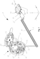
- Fig. 1 shows a first exemplary embodiment of a security arrangement 1 which is not claimed as such in a schematic perspective view.
- the security arrangement 1 comprises a security device 2, a security cable 3 and an adhesive label 4. These extend along a longitudinal direction X, a transverse direction Y and a height direction Z, which together form a Cartesian coordinate system.
- terms used in the context of this coordinate system below refer to the longitudinal direction X, left and right to the transverse direction Y and above or below to the height direction Z.
- the security device 1 has a housing 20 that is designed to be closable by a cover 21.
- the security arrangement 1 can be fixed on the housing 20 or on the cover 21 to any object, for example another object to be secured (not shown).
- the lid is provided with a closure 22 with which it can be locked on or relative to the housing 20 in a closed position (not shown).
- An interior 22 of the security device 2 can be closed with the cover 21.
- a plug receptacle 24 is arranged so that it can be secured against unauthorized access from the outside.
- Means 25 of the security device 2 for generating an alarm or at least parts thereof can also be arranged in the interior 22 protected from external access.
- a bushing 26 is formed on the housing 20, via which the security cable 3 is guided into the interior 23 in order to be electrically connected to the security device 2 at the plug receptacle 24.
- strain relief elements 27 of the securing device 2 are arranged in the interior 23, more precisely on its floor 28.
- the security cable 3 is usually designed with two wires and has a plug element 30 that is inserted into the plug receptacle 24 of the security device 2.
- a strain relief section 31 of the security cable 3 adjoins the plug element 30.
- the strain relief section 31 is held by the strain relief elements 27 of the securing device 2.
- the strain relief section 31 is guided through the strain relief elements 27 with a meandering course.
- a feedthrough section 32 of the safety cable 3 adjoins the strain relief section 31. With the feedthrough section 32, the security cable 3 is guided through the feedthrough 26 of the housing 20 into the surroundings of the housing 20.
- An extension section 33 of the security cable 3 adjoins the feedthrough section 32.
- the extension section 33 is shaped as a spiral cable.
- the transition section 34 is followed by a connection section 35, to which the adhesive label 4 is connected.
- the adhesive label 4 has a flexible base layer 40 with a top 40a and a bottom 40b.
- the top 40a points in the height direction Z.
- the bottom 40b points against the height direction Z.
- predetermined breaking lines 41 are formed in the base layer 40.
- the predetermined breaking lines 41 are designed to break if the adhesive label 4 is manipulated or a tensile force acting on the adhesive label 4 via the security cable 3 causes the predetermined breaking lines 41 to break.
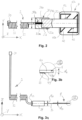
- Fig. 2 shows a schematic bottom view of the security cable 3 and the adhesive label 4, the transition section 34 being shown cut along a plane spanned in the longitudinal direction X and transverse direction Y.
- the transition section 34 is an encapsulation element designed like a housing 34a has.
- the encapsulation member 34a provides an extension retaining portion 34b and a terminal retaining portion 34c, which may be formed as passages with different cross sections.
- connection section 35 is designed, for example, as a flexible circuit board so that it can adapt to the outer contours of an object to be secured. Between the end section 33a of the extension section 33 and the beginning section 35a of the connection section 35 there is a generally two-pole connection point 36 in the transition section 34 between the extension section 33 and the connection section 35.
- connection point 36 is hermetically sealed from the environment in the encapsulation element 34a.
- the end section 33a of the extension section 33 and the beginning section 35a of the connection section 35 are connected to one another in an electrically conductive manner, for example soldered.
- a pair of connection contacts is usually used, which are described below with reference to Figs. 6 and 7 is described in more detail.
- the firm reception of the end section 33a and the beginning section 35a in the extension holding area 34b or connection holding area 34c causes a strain relief of the connection point 36 against tensile forces acting on the extension section 33 or connection section 35 along the safety cable away from the transition section 34.
- the adhesive label 4 is connected to the connection section 35 in an electrically conductive manner.
- the adhesive label 4 is provided on an adhesive or underside 40b with contact surfaces 42 which point towards the connection section 35 against the height direction Z.
- two contact surfaces 42 are provided.
- the two contact surfaces 42 are electrically conductive via a conductor track 43 connected with each other.
- the conductor track 43 is arranged at a distance from an outer edge 40c of the base layer 40.
- Fig. 3a shows the security arrangement 1 or the security cable 3 and the adhesive label 4 in a schematic side view.
- the extension section 33 of the security cable 3 has a thickness or a diameter d 33 .
- the transition section 34 has a thickness or a diameter d 34 .
- the connection section 35 has a thickness d 35 measured essentially parallel to the height direction Z.
- the thickness or diameter d 33 of the extension section 33 is, for example, between 1 and 3 mm, preferably approximately 2 mm.
- the thickness or diameter d 34 of the transition section 34 is, for example, between 6 and 10 mm, preferably approximately 8 mm.
- the thickness d 35 of the connection section 35 is, for example, 0.05 to 0.2 mm, preferably approximately 0.1 mm.
- Fig. 3b shows a detail III Fig. 3a .
- the adhesive label 4 or its base layer 40 has a thickness d 4 measured essentially parallel to the height direction Z, which is, for example, between 0.6 and 1 mm, preferably approximately 0.8 mm.
- d 4 measured essentially parallel to the height direction Z, which is, for example, between 0.6 and 1 mm, preferably approximately 0.8 mm.
- the security cable 3 or its connection section 35 is glued to the adhesive label 4 or its base layer 40 and/or the contact surfaces 42 and/or the conductor track 43.
- Fig. 4 shows the adhesive label 4 in a schematic perspective view, in particular its adhesive or underside 40b can be seen.
- the conductor track 43 is shaped so that it has a large number of deflection points 45 and straight sections 46. At the deflection points 45, the conductor track 43 changes its direction in such a way that the straight sections 46 extend essentially over the entire base layer.
- Fig. 5 shows the adhesive label 4 in a schematic bottom view.
- the conductor track 43 is arranged with its deflection points 45 and the straight sections 46 in such a way that the predetermined breaking lines 41 intersect the conductor track 43 several times. thwart.
- the predetermined breaking lines 41 intersect and form a predetermined breaking line grid 47.
- the predetermined breaking lines 41 each extend to the edges 40c of the base layer 40.
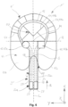
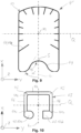
- Fig. 6 shows a claimed embodiment of a security arrangement 1 'or a security cable 3' and an adhesive label 4' in a schematic bottom view.
- the adhesive label 4 ' has a substantially oval-shaped base layer 40.
- a parabolic indentation or recess 48 in the edge 40c of the base layer 40 of the adhesive label 4' forms a transition edge section 49.
- the edge 40c runs at least in sections towards the conductor track 43 and/or the predetermined breaking lines 41 and the predetermined breaking line grid 47 formed therefrom.
- a transition angle ⁇ is formed between the transition edge section 49 and an entry direction E of the security cable 3', along which the security cable 3' is guided under the adhesive label 4'.
- the entry direction E runs essentially parallel to a longitudinal axis L of the connection section 35, which runs parallel to the longitudinal direction X.
- the longitudinal axis L runs essentially perpendicular to a transverse axis Q of the adhesive label 4 ', which in turn runs essentially parallel to the transverse direction Y.
- the predetermined breaking lines 41 of the adhesive label 4' include outer predetermined breaking lines 41a and inner predetermined breaking lines 41b.
- the outer predetermined breaking lines 41a run from the edge 40c essentially radially in the direction of a center point M of the adhesive label 4 'to or beyond the conductor track 43.
- the inner predetermined breaking lines 40b form the predetermined breaking line grid 47 by running towards or crossing one another in an interior space enclosed by the conductor track 43.
- the conductor track 43 is essentially continuously curved or has a curve, which, for example, can be viewed as horseshoe-shaped. In other words, the conductor track 43 describes an almost continuously curved curved path between the two contact surfaces 42.
- the contact surfaces 42 are designed as a first contact surface 42a and a further contact surface 42b.
- the first contact surface 42a is circular in the present exemplary embodiment.
- the further contact surface 42b has a square shape.
- the contact surfaces 42 of the adhesive label 4' are therefore coded. The coding of the contact surfaces 42 facilitates a proper electrical connection of the security cable 3 'to the adhesive label 4'.
- connection section 35 is guided with its connection section 35 under the adhesive label 4' in such a way that an outer edge section 35c of the connection section 35 is arranged in the area of the transition edge section 49.
- connection section 35 is arranged essentially centered in the initial section 35a to the indentation or recess 48, so that the longitudinal axis L in the connection section 35 runs through a vertex S of the recess 48. At the apex S, the recess 48 runs essentially parallel to the transverse axis Q.
- connection contacts 37 are used to establish an electrically conductive connection between the extension section 33 and the connection section 35 in the transition section 34 at the connection point 36.
- the connection contacts 37 are designed, for example, as solder contacts or in the form of solder surfaces.
- Two electrical connection lines 38 extend from the connection contacts 37 and are designed, for example, as flexible conductor tracks that are embedded in the connection section.
- Fig. 7 shows a schematic top view of the security cable 3 '.
- the connection lines 38 run from the connection contacts 37 to the mating contact surfaces 39 of the security cable 3 '.
- the counter-contact surfaces 39 are designed as a first counter-contact surface 39a and as a further counter-contact surface 39b.
- the first mating contact surface 39a is designed to be essentially circular to match the first contact surface 42a of the adhesive label 4'.
- the further mating contact surface 39b is designed to be essentially square to match the further contact surface 42b.
- the contact and mating contact surfaces 42, 39 can be shaped according to the respective requirements in order to achieve a desired assignment or coding.
- the mating contact surfaces 39 are arranged in a head section 35b of the security cable 3 '.
- the connecting lines 38 each curve away from the longitudinal axis L towards the mating contact surfaces 39.
- Fig. 8 shows the adhesive label 4 'in a schematic bottom view.
- the head section 35b of the security cable 3' is fixed to the object using the adhesive label 4'.
- the coded contact surfaces 42 and mating contact surfaces 39 help to properly stick the adhesive label 4 'over the head section 35b in such a way that an electrical contact between contact surfaces 42 and mating contact surfaces 39 that meets the respective requirements is established.
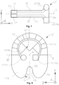
- Fig. 9 shows a further embodiment of an adhesive label 4" according to the invention in a schematic top view.
- the adhesive label 4" is designed to be compatible with the security cable 3'.
- the adhesive label 4 " only has external predetermined breaking lines 41a, which are radial to the center point M run there.
- the indentation or recess 48 of the adhesive label 4" is designed in such a way that the respective transition edge section 49 each runs towards the longitudinal axis L at an entry angle ⁇ '.
- the entry angle ⁇ ' is larger than the entry angle ⁇ in the case of the adhesive label 4'. and can be approximately 45°, for example.
- Fig. 10 shows the contact surfaces 42 and the conductor track 43 of the adhesive label 4".
- the conductor track 43 in turn comprises deflection points 45 and straight sections 46, which together enclose an interior space.
- a contact point 42a of the two contact points 42 is in turn designed to be circular or round at least in sections, whereas the The other contact point 42b of the two contact points 42 is designed to be at least partially angular or rectangular or square.
- a coding of the contact surfaces 42 is therefore also implemented in the adhesive label 4".
- Contact points 42 and conductor track 43 can be in the in Fig. 10 shown form can be cut or punched in one piece from a metal, for example from copper or a copper strip, in order to be glued to the support section 40, for example.
- Contact points 42 and/or conductor track 43 are provided with predetermined breaking points 41c. At the predetermined breaking points 41c, it is easier to break open the contact points 42 or the conductor track 43 if an object provided with the adhesive label 4" is exposed to an attempt at manipulation or theft.
- Fig. 11 shows a further exemplary embodiment according to the invention of a security arrangement 1" or a security cable 3" and an adhesive label 4′′′ in a schematic bottom view.
- the exemplary embodiment of the security cable 3 "has strain relief sections 35d in its connection section 35, which extend laterally away from the edge section 35c on both sides of the connection section 35.
- the strain relief sections 35d are arranged in an area of the adhesive label 4 'that is free of predetermined breaking lines 41.
- the tongue-like strain relief sections 35d expand the adhesive area 44 to the side of the connection section 35 transversely to the longitudinal axis L and help forces, in particular tensile forces, acting on the connection section 35 parallel to the transverse direction Y from the direction of the initial section 35a, from the securing cable 3" to the adhesive label 4′′′ transferred without them becoming detached from one another or shifting relative to one another along the transverse direction Y.
- the strain relief sections 35d can thus compensate for the stability of the connection between the security cable 3′′ and the adhesive label 4′′′ along the longitudinal direction X and transverse direction Y. In other words, the strain relief section 35d contributes to ensuring that the connection between the security cable 3′′ and the adhesive label 4′′′ has essentially the same stability in the longitudinal direction X and transverse direction Y.
- the adhesive label 4′′′ measured parallel to the longitudinal axis L, is shorter than the adhesive label 4′′ described above.
- At least some of the predetermined breaking lines 41 of the adhesive label 4′′′ are dimensioned such that they extend from the edge 40c to over the conductor track 43.
- the predetermined breaking lines 41 coincide with predetermined breaking points 41c attached to the conductor track 43.
- predetermined breaking lines 41 and/or predetermined breaking points 41c intersect the conductor track 43 at least partially transversely to the course of the conductor track 43.
- Fig. 12 shows a schematic top view of the safety cable 3".
- the strain relief sections 35d are arranged in the longitudinal direction X in front of the head section 35b and extend from the edge section on both sides of the connection section 35 35c in or against the transverse direction Y.
- the strain relief sections 35d thus form a hammerhead-like shape. Similar to the head section 35b, transitions between the strain relief section 35d and the edge section 35c are rounded in order to prevent the connection section 35 from tearing at the transitions.
- Fig. 12 shown how in the transition section 34 of the security cable 3" the initial section 35a of the connection section 35 is received in the transparently shown encapsulation member 34a and connected to the extension section 33 of the security cable 3".
- the end section 33a of the security cable 3" is guided in the longitudinal direction
- the electrical conductors 33c are each electrically conductively connected to one of the two connection contacts 37 at the connection points 36.
- the connection can be formed, for example, by soldering or the like.
- the extension section 33 is provided with a strain relief element 33d and the connection section 35 is provided with an upper fixing element 35e. Strain relief element 33d and upper fixing element 35e are accommodated in a form-fitting manner in the encapsulation element 34a.
- Fig. 13 shows the transition section 34 of the security cable 3", in particular parts of the security cable 3" adjacent to the connection points 36, with the encapsulation element 34a omitted, in a schematic perspective view.
- the strain relief element 33d is placed over the casing 33b at the extension section 33 and can surround an end of the casing 33b pointing in the direction of the free electrical conductors 33c or be essentially flush with it.
- the strain relief element 33d can be connected both to the casing 33b and to the electrical conductors 33c or one around them around at least sections remaining second individual casing be positively, non-positively, cohesively and / or connected by gluing.
- the cuboid upper fixing element 35e is arranged on the top of the connection section 35 in the immediate vicinity of the connection contacts 37 and can be fastened positively, non-positively, cohesively and/or by gluing.
- a lower fixing element 35f is arranged, which is also cuboid-shaped and can be fastened positively, non-positively, cohesively and/or by gluing.
- the lower fixing element 35f covers an area of the underside of the connection section 35, opposite which the upper fixing element 35e and the connecting contacts 37 are arranged on the top side.
- connection points 36 are protected from mechanical stresses, in particular bending, and on the other hand a three-dimensional outer contour is provided for positively holding the end section 35a of the connection section 35 in the encapsulation element 34a.
- Fig. 14 shows a schematic cross-sectional view of the transition section 34 of the safety cable 3" in the area of the connection points 36.
- the encapsulation element 34a surrounds the end section 33a, the strain relief element 33d attached thereto as well as the beginning section 35a and the fixing elements 35e, 35f attached therein.
- the encapsulation element 34a can be around the Fuse cable 3" can be crimped and/or thermoplastically shaped or designed as a type of crimp sleeve.
- the encapsulation member 34a forms a cavity-like interior 34d, in which the electrical conductors 33c are housed protected from harmful environmental influences and mechanical influences.
- the strain relief element 33d is held in a form-fitting manner in the extension holding area 34b of the encapsulation member 34a.
- form-fitting elements 34e in the form of projections, shoulders and/or the like are formed on the extension holding area 34b, which limit a range of movement for the strain relief elements 33d at least in and against the longitudinal direction X.
- the extension holding area 34b is designed to be complementary to the sleeve-shaped strain relief element 33d, so that the strain relief element 33d is received as tightly as possible in the extension holding area 34b.
- connection holding area 34c The fixing elements 35e, 35f are held in a form-fitting manner in the connection holding area 34c of the encapsulation element 34a.
- the connection holding area 34c is also provided with positive locking elements 34e in the form of projections, shoulders and/or the like, which limit a range of movement for the fixing elements 35e, 35f at least in and against the longitudinal direction X.
- the connection holding area 34c is therefore designed to be complementary to the fixing elements 35e, 35f, so that they are accommodated as tightly as possible in the connection holding area 34c.
- a security arrangement 1, 1', 1" according to the invention can therefore comprise any number of security devices 2, security cables 3, 3', 3" and adhesive labels 4, 4', 4", 4" in accordance with the respective requirements can be designed and shaped to secure an object from manipulation and/or theft.
- the safety device 2 can be equipped with housings 20, covers 21, closures 22, interior spaces 23, plug receptacle 24, means 25 for generating an alarm, bushings 26, strain relief elements according to the respective requirements 27 and/or bases 28 may be provided in order to be able to connect at least one security cable 3, 3', 3" to the security device 2 in order to secure an object from manipulation and/or theft.
- the security device 2 does not necessarily have to be as shown here be designed, but can be constructed in any other way in order to electronically monitor the condition of the security cable 3, 3 ', 3 "or adhesive label 4, 4 ', 4", 4 "as an alarm device or security system.
- the safety cable 3, 3', 3" can have plug elements 30, strain relief sections 31, feedthrough sections 32, extension sections 33, end sections 33a, sheaths 33b, electrical conductors 33c, strain relief elements 33d, transition sections 34, encapsulation elements 34a, extension holding areas 34b, connection holding areas 34c according to the respective requirements , Interiors 34d, shape elements 34E, connection sections 35, initial sections 35a, head section 35b, edge sections 35c, strain relief sections 35d, upper fixation elements 35e, lower fixation 36, connection contacts 38, connection lines 38, counter -contact surfaces 39a and/or other counter areas 39b in order to electrically conductively connect the security device 2 to adhesive labels 4, 4', 4" in accordance with the respective requirements and thereby cooperate in a suitable manner with the adhesive labels 4, 4', 4" to trigger an alarm through the security device 2 in the event of manipulation or theft of an object to be secured.
- the adhesive label 4, 4', 4" can have supporting layers 40, top sides 40a, undersides or adhesive sides 40b, edges 40c, predetermined breaking lines 41, outer predetermined breaking lines 41a, inner predetermined breaking lines 41b, predetermined breaking points 41c, contact surfaces 42, first contact surfaces 42a according to the respective requirements , further contact surfaces 42b, conductor tracks 43, adhesive areas 44, deflection points 45, straight sections 46, predetermined breaking line grid 47, recesses 48 and / or transition edge sections 49 in order to cooperate with the safety cable 3, 3 'to trigger a To cause an alarm through the security device 2 in the event of manipulation or theft of an object to be secured.
Landscapes
- Physics & Mathematics (AREA)
- General Physics & Mathematics (AREA)
- Burglar Alarm Systems (AREA)
Description
Die vorliegende Erfindung betrifft ein Klebeetikett zum Anbringen eines Sicherungskabels einer elektronischen Sicherungsvorrichtung an einem gegen Diebstahl und/oder Manipulation zu sichernden Objekt.The present invention relates to an adhesive label for attaching a security cable of an electronic security device to an object to be secured against theft and/or manipulation.
Des Weiteren betrifft die Erfindung ein Sicherungskabel für eine elektronische Sicherungsvorrichtung zum Sichern eines Objektes gegen Diebstahl und/oder Manipulation.The invention further relates to a security cable for an electronic security device for securing an object against theft and/or manipulation.
Ferner betrifft die Erfindung eine Sicherungsanordnung zum Sichern eines Objektes gegen Diebstahl und/oder Manipulation.The invention further relates to a security arrangement for securing an object against theft and/or manipulation.
Schließlich betrifft die Erfindung ein Verfahren zur Sicherung eines Objektes gegen Diebstahl und/oder Manipulation.Finally, the invention relates to a method for securing an object against theft and/or manipulation.
Zur Sicherung von Waren in Ladengeschäften gegen Diebstahl haben sich elektronische Warensicherungssysteme bewährt. An den zu sichernden Waren werden dabei sogenannte Tags angebracht, welche durch die Elektronik des Systems über meist am Ausgang der Ladengeschäfte angeordnete Antennen detektierbar sind. Bei den Tags handelt es sich z.B. um elektrische Resonanzschwingkreise mit Resonanzfrequenzen im Radiofrequenzbereich (einige MHz).Electronic article surveillance systems have proven successful in protecting goods in stores against theft. So-called tags are attached to the goods to be secured, which can be detected by the system's electronics via antennas usually located at the exit of the shops. The tags are, for example, electrical resonant circuits with resonance frequencies in the radio frequency range (a few MHz).
Damit die Sicherung funktioniert, müssen die Tags mit den zu sichernden Waren so verbunden sein, dass sie von Unbefugten nicht einfach und unbemerkt entfernt werden können. Bei Kleidungsstücken wird dies z.B. dadurch erreicht, dass eine Nadel durch den Stoff gestochen und die Nadelspitze mit einem Schloss gesichert wird, zu dessen Entfernung spezielles Gerät erforderlich ist. Der Tag ist dabei im Nadelkopf (Hard-Tag) oder im Schloss untergebracht. Kleine Gegenstände können in durchsichtigen, verriegelbaren Behältern untergebracht werden, die in ihrem Innern den Tag enthalten.In order for the security to work, the tags must be connected to the goods to be secured in such a way that they cannot be easily and unnoticed by unauthorized persons. In the case of clothing, for example, this is achieved by inserting a needle through the fabric and securing the tip of the needle with a lock, which requires special equipment to remove. The tag is housed in the needle head (hard tag) or in the lock. Small items can be stored in clear, lockable containers that contain the tag inside.
Zur Sicherung von Waren, die in Verpackungen wie Kartons oder dergleichen zum Verkauf kommen, kommen Tags in Gehäusen zum Einsatz, die mit Bändern (oder Kabeln) an den Verpackungen befestigt werden. Bei einer Ausführungsform sind die Bänder elektrisch leitend und werden von einer Elektronik auf elektrischen Durchgang überwacht. Werden die Bänder zum unbefugten Entfernen der Sicherungsvorrichtung durchtrennt, erzeugt die Elektronik einen Alarm. Zum Aufwickeln und Spannen der Bänder ist in den Gehäusen eine Mechanik untergebracht. Da diese nicht beliebig voluminös sein darf, ist ein Verstellungsbereich der Bänder zur Anpassung ihrer Länge begrenzt, was ihre Anwendung auf Verpackungen in einem bestimmten Grössenbereich einschränkt.To secure goods that are sold in packaging such as boxes or the like, tags in housings that are attached to the packaging with straps (or cables) are used. In one embodiment, the bands are electrically conductive and are monitored by electronics for electrical continuity. If the straps are cut to allow the security device to be removed without authorization, the electronics generate an alarm. A mechanism is housed in the housings for winding and tensioning the straps. Since this cannot be as voluminous as desired, the band's adjustment range for adjusting its length is limited, which limits its application to packaging in a certain size range.
In der
Bei geeigneter geometrischer Anordnung kann mit solchen Bändern auch verhindert werden, dass die Verpackungen geöffnet werden. Häufig wird der Inhalt der Verpackung beim Kauf nicht kontrolliert. Beim Auspacken zu Hause kann sich dann herausstellen, dass der Inhalt den Erwartungen nicht entspricht. Dies kann dadurch verursacht sein, dass die Verpackung beim Transport, im Lager oder im Verkaufsgeschäft geöffnet und die darin enthaltene Ware entnommen und möglicherweise gegen eine andere, meist minderwertige Ware ausgetauscht wurde. Auch werden hochwertige, teure Waren nicht selten in Verpackungen billigerer Waren platziert, um an der Kasse nur den niedrigeren Preis der billigeren Ware bezahlen zu müssen.With a suitable geometric arrangement, such tapes can also prevent the packaging from being opened. The contents of the packaging are often not checked when purchasing. When you unpack it at home, it may turn out that the contents do not meet expectations. This may be caused by the packaging being opened during transport, in the warehouse or in the sales outlet and the goods contained therein being removed and possibly exchanged for another, usually inferior, product. It is also not uncommon for high-quality, expensive goods to be placed in packaging for cheaper goods in order to only have to pay the lower price of the cheaper goods at the checkout.
In der Patentanmeldung
Die Mittel zur Erzeugung eines Alarms umfassen einen mechanischen und/oder einen optischen Sensor. Der mechanische Sensor kann im geschlossenen Zustand durch die Basisplatte einen Kontakt mit dem Objekt detektieren und auf Kontaktverlust mit dem Objekt reagieren. Der optische Sensor emittiert im geschlossenen Zustand Licht durch die Basisplatte, kann Reflexionen dieses Lichtes vom Objekt durch die Basisplatte erfassen und auf Veränderungen dieser Reflexionen reagieren. Die in der Patentanmeldung
Bei aus dem Stand der Technik bekannten Vorrichtungen und Mitteln zur Sicherung von Objekten ist von Nachteil, dass diese sich nur schwer an Objekten mit gekrümmter Oberfläche oder sonstigen Oberflächenunregelmäßigkeiten anbringen lassen, insbesondere wenn die Objekte relativ klein sind, wie beispielsweise Computermäuse, Uhren, Rasierköpfe oder Ähnliches. Ein Beispiel zur Sicherung von Objekten wird in
Die Erfindung stellt sich die Aufgabe, ein Klebeetikett, ein Sicherungskabel, eine Sicherungsanordnung und ein Verfahren zum Sichern eines Objektes gegen Diebstahl und/oder Manipulation der eingangs genannten Art anzugeben, welche sich bei relativ kleinen Objekten mit gekrümmten Oberflächen so anwenden lassen, dass keine aufwendige Mechanik benötigt und dennoch ein ausreichender Schutz gewährleistet wird.The invention aims to provide an adhesive label, a security cable, a security arrangement and a method for securing an object against theft and/or manipulation of the type mentioned at the outset, which can be used on relatively small objects with curved surfaces. that no complex mechanics are required and sufficient protection is still guaranteed.
Diese und andere Aufgaben werden zumindest ansatzweise gelöst durch ein Klebeetikett gemäß Anspruch 1, durch ein Sicherungskabel gemäß Anspruch 13, durch eine Sicherungsanordnung gemäß Anspruch 14 und durch ein Verfahren gemäß Anspruch 15. Weitere bevorzugte Ausführungsformen sind in den abhängigen Ansprüchen angegeben.These and other tasks are at least partially solved by an adhesive label according to
Insbesondere werden die Nachteile aus dem Stand der Technik bei einem Klebeetikett dadurch überwunden, dass das Klebeetikett eine flexible Tragschicht umfasst, die eine Klebeseite ausbildet, an der das Klebeetikett am Objekt anzukleben ist. Des Weiteren weist das Klebeetikett wenigstens eine elektrische Leiterbahn auf, die mit wenigstens einer in der Klebeseite liegenden Kontaktfläche zum elektrischen Kontaktieren des Sicherungskabels elektrisch leitend verbunden ist. Beispielsweise kann die Tragschicht folienartig ausgebildet sein. Die Tragschicht, die wenigstens eine Leiterbahn und die wenigstens eine Kontaktfläche lassen sich beispielsweise als flexible gedruckte Leiterplatte (Printed Circuit Board -PCB) ausbilden.In particular, the disadvantages of the prior art in an adhesive label are overcome in that the adhesive label comprises a flexible backing layer which forms an adhesive side to which the adhesive label is to be adhered to the object. Furthermore, the adhesive label has at least one electrical conductor track, which is electrically conductively connected to at least one contact surface located on the adhesive side for electrically contacting the security cable. For example, the base layer can be designed like a film. The support layer, the at least one conductor track and the at least one contact surface can be designed, for example, as a flexible printed circuit board (PCB).
Diese Ausgestaltungsform eines erfindungsgemäßen Klebeetiketts hat den Vorteil, dass das Klebeetikett durch die Flexibilität seiner Tragschicht auf gekrümmten Oberflächen befestigt werden kann. Die Befestigung am Objekt erfolgt durch Ankleben des Etikettes an seiner Klebeseite, wobei eine in der Regel nicht klebende Oberseite des Klebeetiketts nach oben weist. Im gleichen Zuge kann das Sicherungskabel mit Hilfe des Etiketts am Objekt fixiert werden, indem das Kabel zumindest abschnittsweise mit dem Etikett überklebt wird. Durch die Sicherungsvorrichtung kann dann die wenigstens eine Leiterbahn elektrisch überwacht werden. Beispielsweise kann überwacht werden, ob ein über die wenigstens eine Kontaktfläche des Etikettes, die wenigstens eine Leiterbahn und wenigstens eine Gegenkontaktfläche des Sicherungskabels führender elektrischer Überwachungsstromkreis auf eine Manipulation und/oder einen Diebstahl des Objektes Aufschluss gibt.This embodiment of an adhesive label according to the invention has the advantage that the adhesive label can be attached to curved surfaces due to the flexibility of its base layer. It is attached to the object by sticking the label to its adhesive side, with a generally non-adhesive top side of the adhesive label facing upwards. At the same time, the security cable can be fixed to the object using the label by at least partially covering the cable with the label. The safety device can then be used to electrically monitor the at least one conductor track. For example, it can be monitored whether an electrical monitoring circuit leading over the at least one contact surface of the label, the at least one conductor track and at least one mating contact surface of the security cable provides information about manipulation and / or theft of the object.
Gemäß einer weiteren möglichen Ausführungsform des Klebeetiketts ist vorgesehen, dass die Klebeseite und/oder die wenigstens eine Kontaktfläche zumindest abschnittsweise mit einer isotrop und/oder anisotrop elektrisch leitenden Klebschicht versehen sind, deren elektrische Leitfähigkeit entlang einer senkrecht zur Klebeseite verlaufenen Kontaktrichtung größer ist als in einer von der Tragschicht aufgespannten Befestigungsebene des Klebeetiketts. Eine isotrop leitende Klebschicht kann unter Umständen mechanisch stabiler sein als eine anisotrop leitende Klebschicht. Durch eine zumindest abschnittsweise anisotrop elektrisch leitende Klebschicht lässt sich die wenigstens eine Kontaktfläche des Klebeetiketts unter möglichst geringem elektrischen Widerstand über die Klebschicht mit der wenigstens einen Gegenkontaktfläche des Sicherungskabels elektrisch leitend verbinden. Es wird verhindert, dass entlang der Klebschicht Kriechströme entlang der Befestigungsebene fließen, welche eine elektrische Überwachung durch die Sicherungsvorrichtung beeinträchtigen könnten.According to a further possible embodiment of the adhesive label, it is provided that the adhesive side and/or the at least one contact surface are provided at least in sections with an isotropically and/or anisotropically electrically conductive adhesive layer, the electrical conductivity of which is greater along a contact direction running perpendicular to the adhesive side than in one The attachment level of the adhesive label spanned by the base layer. An isotropically conductive adhesive layer can under certain circumstances be mechanically more stable than an anisotropically conductive adhesive layer. By means of an at least partially anisotropically electrically conductive adhesive layer, the at least one contact surface of the adhesive label can be electrically conductively connected via the adhesive layer to the at least one mating contact surface of the security cable with the lowest possible electrical resistance. Leakage currents, which could impair electrical monitoring by the safety device, are prevented from flowing along the adhesive layer along the fastening level.
Alternativ oder zusätzlich kann lediglich der Tragabschnitt mit einem nicht leitenden Kleber versehen sein. Unter Umständen ist bei dieser Ausführungsform ein elektrischer Widerstand zwischen Leiterbahn bzw. Kontaktfläche und zu sichernden Objekt stabiler als bei der Ausführung mit anisotrop leitender Klebschicht auf Kontaktfläche und Leiterbahn. So kann beispielsweise allein durch die Anpresskraft des nicht leitenden Klebers auf der Tragschicht um die Kontaktflächen herum ein stabiler elektrischer Widerstand von ca. 1 bis 2 Ohm, vorzugsweise ca. 1,5 Ohm herrschen.Alternatively or additionally, only the support section can be provided with a non-conductive adhesive. In this embodiment, an electrical resistance between the conductor track or contact surface and the object to be secured may be more stable than in the version with an anisotropically conductive adhesive layer on the contact surface and conductor track. For example, a stable electrical resistance of approximately 1 to 2 ohms, preferably approximately 1.5 ohms, can prevail around the contact surfaces solely due to the contact pressure of the non-conductive adhesive on the base layer.
Gemäß einer weiteren möglichen Ausführungsform des Klebeetiketts ist vorgesehen, dass die wenigstens eine elektrische Leiterbahn und/oder die wenigstens eine Kontaktfläche sich zumindest abschnittsweise von der Tragschicht vor wölbt bzw. wölben. In dem die wenigstens eine elektrische Leiterbahn und/oder die wenigstens eine Kontaktfläche sich von der Tragschicht vor wölben kann ein sicherer elektrischer Kontakt zwischen dem Klebeetikett und dem zu sichernden Objekt bzw.According to a further possible embodiment of the adhesive label, it is provided that the at least one electrical conductor track and/or the at least one contact surface bulges or bulges at least in sections from the base layer. In that the at least one electrical conductor track and/or the at least one contact surface protrude from the base layer, a secure electrical contact can be established between the adhesive label and the object or object to be secured.
Klebeetikett und Sicherungskabel hergestellt werden. Auch bei dieser Ausführungsform kann auf die anisotrop elektrisch leitende Klebschicht verzichtet werden. Im Wesentlichen kann der Bereich der Leiterbahn bzw. der Kontaktflächen Kleberfrei gehalten sein.Adhesive label and safety cable are produced. In this embodiment too, the anisotropically electrically conductive adhesive layer can be dispensed with. Essentially, the area of the conductor track or the contact surfaces can be kept glue-free.
Beispielsweise kann die Wölbung der Leiterbahn bzw. der Kontaktfläche schon bei deren Herstellung geformt werden. So können Leiterbahn und Kontaktfläche beispielsweise einstückig aus einem Kupferband geschnitten und/oder gestanzt sein. Beim Schneide- bzw. Stanzvorgang können die Kanten von Leiterbahn und Kontaktfläche leicht gebogen werden, sodass es zu besagter Wölbung kommt. Wenn dann das Kupferband auf den Tragabschnitt übertragen wird, wobei die gebogenen Kanten zum Tragabschnitt hinweisen, wölbt sich das Kupferband vom Tragabschnitt bzw. der Klebeseite vor.For example, the curvature of the conductor track or the contact surface can be shaped during their production. For example, the conductor track and contact surface can be cut and/or punched in one piece from a copper strip. During the cutting or punching process, the edges of the conductor track and contact surface can be slightly bent, resulting in the aforementioned curvature. When the copper tape is then transferred to the support section, with the curved edges pointing towards the support section, the copper tape bulges from the support section or the adhesive side.
Gemäß einer weiteren möglichen Ausführungsform des Klebeetiketts ist vorgesehen, dass die wenigstens eine elektrische Leiterbahn und/oder die wenigstens eine Kontaktfläche in die Tragschicht eingebettet sind. Diese Ausführungsform hat den Vorteil, dass das Klebeetikett eine sehr ebene Klebeseite aufweist, die sich gekrümmten und unebenen Oberflächen sehr gut anpassen kann. Lufteinschlüsse zwischen Klebeseite und Objekt und/oder Sicherungskabel werden vermieden. Das Klebeetikett kann möglichst vollflächig am Objekt und/oder Sicherungskabel anliegen, um eine stabile Klebung und engen Kontakt am Objekt zu gewährleisten.According to a further possible embodiment of the adhesive label, it is provided that the at least one electrical conductor track and/or the at least one contact surface are embedded in the base layer. This embodiment has the advantage that the adhesive label has a very flat adhesive side that can adapt very well to curved and uneven surfaces. Air pockets between the adhesive side and the object and/or securing cable are avoided. The adhesive label can rest as fully as possible on the object and/or security cable in order to ensure stable adhesion and close contact with the object.
Dabei kann die Tragschicht die wenigstens eine Leiterbahn und/oder die wenigstens eine Kontaktfläche seitlich überragen. Selbst wenn es in einem Randbereich des Klebeetiketts zu Verwerfungen kommen würde, könnte diese im die Leiterbahn und/oder die Kontaktfläche überragenden Bereich der Tragschicht liegen. Dies hilft, einen möglichst ununterbrochenen Klebekontakt zwischen der Leiterbahn und/oder der Kontaktfläche einerseits und der Gegenkontaktfläche des Sicherungskabels sowie des Objektes andererseits zu gewährleisten.The support layer can project laterally beyond the at least one conductor track and/or the at least one contact surface. Even if there were distortions in an edge area of the adhesive label, these could be in the area of the base layer that projects beyond the conductor track and/or the contact surface. This helps to ensure the most uninterrupted adhesive contact possible between the conductor track and/or the contact surface on the one hand and the mating contact surface of the security cable and the object on the other hand.
Gemäß einer weiteren möglichen Ausführungsform des Klebeetiketts ist vorgesehen, dass die Tragschicht wenigstens eine Sollbruchlinie aufweist, welche die wenigstens eine Leiterbahn kreuzt. Die wenigstens eine Sollbruchlinie erleichtert, dass das Klebeetikett bei dessen Manipulation und/oder bei Manipulation des Sicherungskabels entlang der Sollbruchlinie einreist und dass sich der Riss über die Leiterbahn hinweg fortsetzt, sodass diese unterbrochen wird und die Unterbrechung mit Hilfe der Sicherungsvorrichtung detektiert werden kann.According to a further possible embodiment of the adhesive label, it is provided that the base layer has at least one predetermined breaking line which crosses the at least one conductor track. The at least one predetermined breaking line makes it easier for the adhesive label to tear along the predetermined breaking line when it is manipulated and/or when the security cable is manipulated and for the crack to continue across the conductor track, so that it is interrupted and the interruption can be detected with the aid of the security device.
Gemäß einer weiteren möglichen Ausführungsform des Klebeetiketts ist vorgesehen, dass die wenigstens eine Sollbruchlinie bzw. das Sollbruchgitter sich bis zu einem äußeren Rand der Tragschicht erstreckt. Somit kann im Falle einer Manipulation des Klebeetiketts beim Versuch dieses von einem zu sichernden Objekt zu entfernen oder durch die über das Sicherheitskabel beim Diebstahlversuch auf das Klebeetikett einwirkenden Kräfte dieses entlang der Sollbruchlinie vom Rand aus und/oder oder bis zum Rand hin zuverlässig einreissen, um somit die wenigstens eine Leiterbahn zu beschädigen und den Manipulation- bzw. Diebstahlversuch zuverlässig detektierbar zu machen.According to a further possible embodiment of the adhesive label, it is provided that the at least one predetermined breaking line or the predetermined breaking grid extends to an outer edge of the base layer. Thus, in the event of manipulation of the adhesive label when attempting to remove it from an object to be secured or due to the forces acting on the adhesive label via the security cable when attempting to steal it, it can reliably tear along the predetermined breaking line from the edge and/or up to the edge thus damaging the at least one conductor track and making the attempted manipulation or theft reliably detectable.
Gemäß einer weiteren möglichen Ausführungsform des Klebeetiketts ist vorgesehen, dass die wenigstens eine Leiterbahn mit wenigstens einer Sollbruchstelle versehen ist. Die wenigstens eine Sollbruchstelle kann durch anritzen oder -schneiden der wenigstens einen Leiterbahn geformt sein. Beispielsweise kann die wenigstens eine Sollbruchstelle in ein Kupferband getrieben oder geritzt sein, aus dem Leiterbahn und/oder Kontaktfläche gebildet werden oder sind. Indem die Leiterbahn mit einer Sollbruchstelle versehen ist, kann sichergestellt sein, dass die Leiterbahn bei Manipulation oder Diebstahlversuch an der Sollbruchstelle zuverlässig bricht, um somit die Auslösung eines Alarms zu bewirken.According to a further possible embodiment of the adhesive label, it is provided that the at least one conductor track is provided with at least one predetermined breaking point. The at least one predetermined breaking point can be formed by scoring or cutting the at least one conductor track. For example, the at least one predetermined breaking point can be driven or scratched into a copper strip from which the conductor track and/or contact surface are or are formed. By providing the conductor track with a predetermined breaking point, it can be ensured that the conductor track breaks reliably at the predetermined breaking point in the event of manipulation or attempted theft, thereby triggering an alarm.
Gemäß einer weiteren möglichen Ausführungsform des Klebeetiketts ist vorgesehen, dass an der Tragschicht ein Kabeleintrittsbereich, an dem das Sicherungskabel von außen unter das Klebeetikett zu führen ist, mit einer Einbuchtung oder Ausnehmung ausgeformt ist, die wenigstens einen Übergangsrandabschnitt umfasst, der zumindest abschnittsweise in Richtung zur wenigstens einen Leiterbahn hin verläuft. Der Kabeleintrittsbereich kann generell so ausgeformt sein, dass er ein Fixieren des Sicherungskabels relativ zum Klebeetikett und zum Objekt vereinfacht. Um eine gewisse Zugentlastung gewähren zu können, kann der Kabeleintrittsbereich im Wesentlichen frei von Sollbruchlinien sein. Die Einbuchtung hilft dabei, das Sicherungskabel relativ zum Klebeetikett präzise zu positionieren. Der Übergangsrandabschnitt hilft, bei senkrecht vom Klebeetikett weg am Sicherungskabel wirkenden Zugkräften, wie sie typischerweise bei einem Diebstahl Versuch auftreten können, ein herauslösen des Sicherungskabel aus der Verklebung mit dem Klebeetikett zu begünstigen.According to a further possible embodiment of the adhesive label, it is provided that on the base layer there is a cable entry area on which the security cable is to be guided from the outside under the adhesive label, is formed with an indentation or recess which comprises at least one transition edge section which extends at least in sections towards the at least one conductor track. The cable entry area can generally be shaped in such a way that it simplifies fixing the security cable relative to the adhesive label and the object. In order to be able to provide a certain strain relief, the cable entry area can be essentially free of predetermined breaking lines. The indentation helps to precisely position the security cable relative to the adhesive label. The transition edge section helps, when tensile forces act perpendicularly away from the adhesive label on the security cable, as can typically occur in the event of an attempt to steal, to encourage the security cable to be detached from the bond to the adhesive label.
Gemäß einer weiteren möglichen Ausführungsform des Klebeetiketts ist vorgesehen, dass der wenigstens eine Übergangsrandabschnitt zumindest abschnittsweise unter einem Übergangswinkel von weniger als 40°, vorzugsweise weniger als 30° zu einer Eintrittsrichtung hin verläuft, in welcher das Sicherungskabel unter das Klebeetikett zu führen ist. Ein derartiger Übergangswinkel, also insbesondere ein spitzer Winkel zwischen Übergangsabschnitt und Sicherung Kabel, begünstigt, dass das Sicherungskabel durch senkrecht vom Klebeetikett weg gerichtete Zugkräfte aus der Verklebung gelöst wird. So kann der Übergangsrandabschnitt beim Auftreten derartiger Zugkräfte das Kabel nicht halten. Eine Klebefläche zwischen Klebeetikett und Kabel läuft im Bereich des Übergangsrandabschnittes derart spitz auf die zeitlichen Außenränder des Kabels zu, dass diese sich einfach von Objekt und Klebeetikett ablösen können. Sobald das Kabel dann einen Scheitelpunkt der Einbuchtung erreicht beginnt das Klebeetikett vom Scheitelpunkt aus einzureissen.According to a further possible embodiment of the adhesive label, it is provided that the at least one transition edge section runs at least in sections at a transition angle of less than 40°, preferably less than 30°, towards an entry direction in which the security cable is to be guided under the adhesive label. Such a transition angle, i.e. in particular an acute angle between the transition section and the securing cable, promotes the securing cable being released from the bond by tensile forces directed vertically away from the adhesive label. The transition edge section cannot hold the cable when such tensile forces occur. In the area of the transition edge section, an adhesive surface between the adhesive label and the cable tapers so sharply towards the temporal outer edges of the cable that they can easily detach from the object and the adhesive label. As soon as the cable reaches a vertex of the indentation, the adhesive label begins to tear from the vertex.
Gemäß einer weiteren möglichen Ausführungsform des Klebeetiketts ist vorgesehen, dass die wenigstens eine Leiterbahn einen bogenförmigen Verlauf aufweist. Beispielsweise kann die Leiterbahn bogenförmigen von der wenigstens einen Kontaktfläche aus zu einer weiteren Kontaktfläche verlaufen. Durch einen derartigen Verlauf kann die Leiterbahn beispielsweise zumindest abschnittsweise parallel zu einem äußeren Rand des Klebeetiketts angeordnet sein, um dort im Falle eines Manipulations- oder Diebstahlversuchs schnell und zuverlässig Schaden zu nehmen.According to a further possible embodiment of the adhesive label, it is provided that the at least one conductor track has an arcuate course. For example, the conductor track can extend in an arc from the at least one contact surface to a further contact surface. Through such a thing The conductor track can, for example, be arranged at least in sections parallel to an outer edge of the adhesive label in order to be damaged quickly and reliably in the event of an attempted manipulation or theft.
Gemäß einer weiteren möglichen Ausführungsform des Klebeetiketts ist vorgesehen, dass die wenigstens eine Leiterbahn an wenigstens einem Knick oder wenigstens einer Kurve umgelenkt ist. Durch das abknicken oder umlenken kann die Leiterbahn möglichst weiträumige Bereiche des Klebeetiketts durchkreuzen. Durch die weitläufige Abdeckung des Klebeetiketts mit der Leiterbahn können Manipulationen oder Beschädigungen des Klebeetiketts in möglichst vielen Abschnitten des Etiketts detektierbar gemacht werden. Insbesondere von Vorteil kann dabei sein, wenn die Leiterbahn entlang ihres kurvigen bzw. mit Knicken versehenden Verlaufs mehrfach von Sollbruchlinien durchkreuzt ist.According to a further possible embodiment of the adhesive label, it is provided that the at least one conductor track is deflected at at least one bend or at least one curve. By bending or redirecting, the conductor track can cross as large an area of the adhesive label as possible. By extensively covering the adhesive label with the conductor track, manipulation or damage to the adhesive label can be made detectable in as many sections of the label as possible. It can be particularly advantageous if the conductor track is crossed several times by predetermined breaking lines along its curved or kinked course.
Anspruchsgemäss ist vorgesehen, dass das Klebeetikett wenigstens eine weitere mit der wenigstens einen Leiterbahn verbundene Kontaktfläche aufweist, und dass die wenigstens eine Kontaktfläche und die wenigstens eine weitere Kontaktfläche zur Kodierung unterschiedliche Konturen aufweisen. Beispielsweise können die Kontaktflächen unterschiedliche Außenkonturen aufweisen. Durch die unterschiedlichen Außenkonturen können die Kontaktflächen einfach voneinander unterschieden und dazugehörigen gegen Kontaktflächen am Sicherungskabel zugeordnet werden. Dies erleichtert ein ordnungsgemäßes Paaren von Klebeetikett und Sicherungskabel.According to the claim, it is provided that the adhesive label has at least one further contact surface connected to the at least one conductor track, and that the at least one contact surface and the at least one further contact surface have different contours for coding. For example, the contact surfaces can have different outer contours. Due to the different outer contours, the contact surfaces can be easily distinguished from one another and assigned to the corresponding contact surfaces on the safety cable. This makes it easier to properly pair the adhesive label and security cable.
Beim eingangs genannten Sicherungskabel kann die erfindungsgemäße Lösung dadurch weiter verbessert werden, dass die wenigstens eine Gegenkontaktfläche in einem folienartig ausgestalteten flexiblen Anschlussabschnitt des Sicherungskabels angeordnet ist. Durch die folienartige Ausgestaltung kann der Anschlussabschnitt eine Dicke von weniger als 1 mm aufweisen und lässt sich somit problemlos mithilfe des Klebeetiketts an einem zu sichernden Objekt fixieren. Die Flexibilität des Anschlussabschnittes ermöglicht, dass sich der Anschlussabschnitt einer Oberflächenkontur des zu sichernden Objektes anpasst, so wie es auch das Klebeetikett tut.In the case of the security cable mentioned at the beginning, the solution according to the invention can be further improved in that the at least one mating contact surface is arranged in a film-like flexible connection section of the security cable. Due to the film-like design, the connection section can have a thickness of less than 1 mm and can therefore be easily fixed to an object to be secured using the adhesive label. The flexibility of the connection section allows the connection section to adapt to a surface contour of the object to be secured, just as the adhesive label does.
Gemäß einer weiteren möglichen Ausführungsform des Sicherungskabels ist der Anschlussabschnitt mit einem Verlängerungsabschnitt des Sicherungskabels elektrisch leitend verbunden, wobei ein Querschnitt des Anschlussabschnittes von einem Querschnitt des Verlängerungsabschnittes abweicht. Der Anschlussabschnitt kann somit zum Anbringen am Objekt optimiert sein. Der Verlängerungsabschnitt hingegen kann im Hinblick auf eine möglichst einfache Handhabung und ein unauffälliges Erscheinungsbild des Sicherungskabels optimiert sein.According to a further possible embodiment of the security cable, the connection section is electrically connected to an extension section of the security cable, with a cross section of the connection section deviating from a cross section of the extension section. The connection section can thus be optimized for attachment to the object. The extension section, on the other hand, can be optimized with a view to making it as easy to handle as possible and to ensure an inconspicuous appearance of the security cable.
Beispielsweise kann das Sicherungskabel zweiadrig ausgestaltet und mit zwei Gegenkontaktflächen versehen sein. Durch die wenigstens eine Leiterbahn des Klebeetiketts können die zwei Adern des Sicherungskabels elektrisch leitend miteinander verbunden, sprich kurzgeschlossen sein. Diese Kurzschlussverbindung kann zur Detektion einer Manipulation bzw. eines Diebstahlversuches eines zu sichernden Objektes genutzt werden.For example, the security cable can be designed with two wires and provided with two mating contact surfaces. Through the at least one conductor track of the adhesive label, the two wires of the security cable can be electrically connected to one another, i.e. short-circuited. This short-circuit connection can be used to detect manipulation or an attempted theft of an object to be secured.
Zusammenwirkend ermöglichen Klebeetikett, Sicherungskabel und Sicherungsvorrichtung als Sicherungsanordnung, dass durch Mittel der Sicherungsvorrichtung zum Überwachen der wenigstens einen Leiterbahn und Mitteln zur Erzeugung eines Alarms eine Manipulation bzw. ein Diebstahlversuch eines zu sichernden Objektes detektiert und angezeigt wird. Jeder Kontaktverlust zwischen Sicherungskabei und Klebeetikett bzw. zwischen Sicherungskabel und einem zu sichernden Objekt führt zu Unterbrechung einer elektrischen Verbindung zwischen den beiden Adern des Kabels. Diese Unterbrechung kann durch die Sicherungsvorrichtung detektiert werden, die infolgedessen einen Alarm auslöst.Together, the adhesive label, security cable and security device as a security arrangement make it possible for manipulation or an attempted theft of an object to be secured to be detected and displayed by means of the security device for monitoring the at least one conductor track and means for generating an alarm. Any loss of contact between the security cable and the adhesive label or between the security cable and an object to be secured leads to an interruption of an electrical connection between the two wires of the cable. This interruption can be detected by the security device, which consequently triggers an alarm.
Gemäß einer weiteren möglichen Ausführungsform eines erfindungsgemäßen Verfahrens kann vorgesehen sein, dass Größe und/oder Form des Klebeetiketts und/oder eine Klebschicht zum ankleben des Klebeetiketts an einem zu sichernden Objekt aus einer Vielzahl verschiedener Typen von Klebeetiketten bzw. Klebschichten in Abhängigkeit von einer Oberflächenbeschaffenheit des zu sichernden Objektes ausgewählt werden. Beispielsweise können verschiedenartige Klebeetiketten unterschiedliche Trägerschichten aufweisen, die einerseits unterschiedlich geformt und andererseits aus unterschiedlichen Materialien gebildet sein können.According to a further possible embodiment of a method according to the invention, it can be provided that the size and/or shape of the adhesive label and/or an adhesive layer for sticking the adhesive label to an object to be secured can be selected from a variety of different types of adhesive labels or adhesive layers depending on a surface quality of the object to be secured. For example, different types of adhesive labels can have different carrier layers, which on the one hand can be shaped differently and on the other hand can be made from different materials.
Verschiedenartige Klebschichten können aus unterschiedlichen Klebern bzw. Klebemitteln gebildet sein. Neben fließenden und aushärtenden Klebstoffen können auch Klebebänder eingesetzt werden. Insbesondere können beidseitig klebende leitende Klebebänder verwendet werden. Auch können Anti-Rutsch-Folien und/oder Gummi-bzw. gummiartige Filme zwischen Klebeetikett und Sicherungskabel eingesetzt werden, um dazwischen den jeweiligen Anforderungen gemäß Zug- und Torsionskräfte übertragen zu können.Different types of adhesive layers can be formed from different adhesives or adhesives. In addition to flowing and hardening adhesives, adhesive tapes can also be used. In particular, double-sided conductive adhesive tapes can be used. Anti-slip films and/or rubber or Rubber-like films can be used between the adhesive label and the safety cable in order to be able to transfer tensile and torsional forces between them according to the respective requirements.
Dabei ist zu berücksichtigen, wie Zug- und Torsionskräfte sich auf den elektrischen Widerstand zwischen Sicherungskabel und Klebeetikett auswirken. So ist es insbesondere wünschenswert, dass der elektrische Widerstand unter Zug bzw. Torsion in einem gewissen Rahmen bleibt, beispielsweise zwischen 5 und 20 Ohm, zwischen 8 und 14 Ohm oder Ähnliches, damit die Sicherungsvorrichtung Manipulationen bzw. Diebstahlversuche zuverlässig von bei üblicher Handhabung des zu sichernden Objektes auftretenden Änderungen der elektrischen Eigenschaften von Sicherungskabel und Klebeetikett sowie der Verbindung zwischen diesen unterscheiden kann.It is important to take into account how tensile and torsional forces affect the electrical resistance between the security cable and the adhesive label. It is particularly desirable that the electrical resistance under tension or torsion remains within a certain range, for example between 5 and 20 ohms, between 8 and 14 ohms or similar, so that the security device reliably protects against manipulation or theft attempts during normal handling of the device When securing the object, changes in the electrical properties of the security cable and adhesive label as well as the connection between them can be distinguished.
Je nach Anwendung kann es sinnvoll sein, dass die Klebschicht bzw. ein Klebstoff oder Klebeband rückstandsfrei vom zu sichernden Objekt und/oder vom Sicherungskabel entfernbar ist. Somit bleibt der Wert des zu sichernden Objektes erhalten bzw. dieses wird nicht durch Kleberrückstände beeinträchtigt. Das Sicherungskabel kann durch rückstandsfreie Entfernbarkeit des Klebers wieder verwendet werden.Depending on the application, it may make sense for the adhesive layer or an adhesive or adhesive tape to be removable from the object to be secured and/or the security cable without leaving any residue. This means that the value of the object to be secured is preserved and it is not affected by adhesive residue. The safety cable can be reused because the adhesive can be removed without leaving any residue.
Klebeetikett, Sicherungskabel und/oder Klebschicht können bei der Herstellung einer erfindungsgemäßen Sicherungsanordnung anwendungsbereit, d.h. als eine an einem zu sichernden Objekt anbringbare Einheit, bereitgestellt werden. Dies vereinfacht die Anwendung einer erfindungsgemäßen Sicherungsanordnung und hilft, unerwünschte Verunreinigungen von Klebeetikett, Sicherungskabel und/oder Klebschicht bei deren Handhabung zu vermeiden.Adhesive label, security cable and/or adhesive layer can be provided ready for use in the production of a security arrangement according to the invention, i.e. as a unit that can be attached to an object to be secured. This simplifies the use of a security arrangement according to the invention and helps to avoid unwanted contamination of the adhesive label, security cable and/or adhesive layer during their handling.
Die Erfindung wird nachfolgend anhand mehrerer Ausführungsbeispiele im Zusammenhang mit den Zeichnungen näher erläutert. Es zeigen:
- Fig. 1
- eine schematische Perspektivansicht einer als solchen nicht anspruchs-gemässen Sicherungsanordnung mit einer erfindungsgemäßen Sicherungsvorrichtung, einem ersten Ausführungsbeispiel eines erfindungs-gemäßen Sicherungskabels und mit einem ersten Ausführungsbeispiel eines erfindungsgemäßen Klebeetiketts;
- Fig. 2
- eine schematische Unteransicht des Sicherungskabels und des Klebeetiketts aus
Fig. 1 ; - Fig. 3a
- eine schematische Seitenansicht des Sicherungskabels und des Klebeetiketts aus
Fig. 1 bzw. 2; - Fig. 3b
- ein Detail III aus
Fig.3a - Fig. 4
- eine schematische Perspektivansicht des in
Figs. 1 bis 3b gezeigten Klebeetiketts; - Fig. 5
- eine schematische Draufsicht des in
Figs. 1 gezeigten Klebeetiketts;bis 4 - Fig. 6
- eine schematische Unteransicht eines Ausführungsbeispiels eines erfin-dungsgemässen Sicherungskabels und eines erfindungsgemässen Klebeetiketts;
- Fig. 7
- eine schematische Unteransicht des in
Fig. 6 gezeigten Sicherungskabels; - Fig. 8
- eine schematische Unteransicht des in
Fig. 6 gezeigten Klebeetiketts. - Fig. 9
- eine schematische Draufsicht auf ein weiteres Ausführungsbeispiel eines erfindungsgemäßen Klebeetiketts;
- Fig. 10
- eine schematische Draufsicht auf Leiterbahn und Kontaktflächen des in
Fig. 9 gezeigten Klebeetiketts; - Fig. 11
- eine schematische Unteransicht eines weiteren Ausführungsbeispiels eines erfindungsgemässen Sicherungskabels und eines erfindungsgemässen Klebeetiketts;
- Fig. 12
- eine schematische Draufsicht des in
Fig. 11 gezeigten Sicherungskabels; - Fig. 13
- eine schematische Perspektivansicht eines Übergangsabschnitts des in
Figs. 11 und12 gezeigten Sicherungskabels; und - Fig. 14
- eine schematische Querschnittsansicht des Übergangsabschnitts des in
Figs. 11 bis 13 gezeigten Sicherungskabels.
- Fig. 1
- a schematic perspective view of a security arrangement, not claimed as such, with a security device according to the invention, a first exemplary embodiment of a security cable according to the invention and with a first exemplary embodiment of an adhesive label according to the invention;
- Fig. 2
- a schematic bottom view of the security cable and the adhesive label
Fig. 1 ; - Fig. 3a
- a schematic side view of the security cable and the adhesive label
Fig. 1 or 2; - Fig. 3b
- a detail III
Fig.3a - Fig. 4
- a schematic perspective view of the in
Figs. 1 to 3b adhesive label shown; - Fig. 5
- a schematic top view of the in
Figs. 1 to 4 adhesive label shown; - Fig. 6
- a schematic bottom view of an exemplary embodiment of a security cable according to the invention and an adhesive label according to the invention;
- Fig. 7
- a schematic bottom view of the in
Fig. 6 fuse cable shown; - Fig. 8
- a schematic bottom view of the in
Fig. 6 adhesive label shown. - Fig. 9
- a schematic top view of a further exemplary embodiment of an adhesive label according to the invention;
- Fig. 10
- a schematic top view of the conductor track and contact surfaces of the in
Fig. 9 adhesive label shown; - Fig. 11
- a schematic bottom view of a further exemplary embodiment of a security cable according to the invention and an adhesive label according to the invention;
- Fig. 12
- a schematic top view of the in
Fig. 11 fuse cable shown; - Fig. 13
- a schematic perspective view of a transition section of the in
Figs. 11 and12 fuse cable shown; and - Fig. 14
- a schematic cross-sectional view of the transition section of the in
Figs. 11 to 13 safety cable shown.
In den Figuren sind übereinstimmende Teile oder Elemente mit denselben Bezugszeichen versehen. Verschiedene Ausführungsbeispiele eines Teils oder Elements sind in der Regel mit der gleichen Bezugsnummer bezeichnet, die dem jeweiligen Ausführungsbeispiel entsprechend mit einem oder mehreren Apostrophen versehen ist.In the figures, corresponding parts or elements are provided with the same reference numerals. Different exemplary embodiments of a part or element are usually designated with the same reference number, which is provided with one or more apostrophes corresponding to the respective exemplary embodiment.
Die Sicherungsvorrichtung 1 besitzt ein Gehäuse 20, dass durch einen Deckel 21 verschließbar ausgestaltet ist. Die Sicherungsanordnung 1 kann am Gehäuse 20 oder am Deckel 21 beliebig an einem Gegenstand, beispielsweise einem weiteren zu sichernden Objekt (nicht gezeigt) fixiert werden. Der Deckel ist mit einem Verschluss 22 versehen, mit dem er am bzw. gegenüber dem Gehäuse 20 in einer geschlossenen Stellung (nicht gezeigt) arretierbar ist. Mit dem Deckel 21 ist ein Innenraum 22 der Sicherungsvorrichtung 2 verschließbar.The
Im Innenraum 23 ist eine Steckeraufnahme 24 vor einem unbefugten Zugriff von außen sicherbar angeordnet. Mittel 25 der Sicherungsvorrichtung 2 zum Erzeugen eines Alarms oder zumindest Teile davon können ebenfalls im Innenraum 22 vor äußeren Zugriffen geschützt angeordnet sein. Am Gehäuse 20 ist eine Durchführung 26 ausgeformt, über die das Sicherungskabel 3 in den Innenraum 23 geführt ist, um an der Steckeraufnahme 24 elektrisch leitend mit der Sicherungsvorrichtung 2 verbunden zu werden. Des Weiteren sind Zugentlastungselemente 27 der Sicherungsvorrichtung 2 im Innenraum 23, genauer gesagt an dessen Boden 28, angeordnet.In the interior 23, a plug receptacle 24 is arranged so that it can be secured against unauthorized access from the outside. Means 25 of the
Das Sicherungskabel 3 ist in der Regel zweiadrig ausgeführt und besitzt ein Steckerelement 30, dass in die Steckeraufnahme 24 der Sicherungsvorrichtung 2 eingesteckt ist. An das Steckerelement 30 schließt sich ein Zugentlastungsabschnitt 31 des Sicherungskabels 3 an. Der Zugentlastungsabschnitt 31 ist von den Zugentlastungselementen 27 der Sicherungsvorrichtung 2 gehalten. Im vorliegenden Ausführungsbeispiel ist der Zugentlastungsabschnitt 31 mit einem meandrierendem Verlauf durch die Zugentlastungselemente 27 geführt.The
An den Zugentlastungsabschnitt 31 schließt sich ein Durchführungsabschnitt 32 des Sicherungskabels 3 an. Mit dem Durchführungsabschnitt 32 ist das Sicherungskabel 3 durch die Durchführung 26 des Gehäuses 20 in die Umgebung des Gehäuses 20 geführt. An den Durchführungsabschnitt 32 schließt sich ein Verlängerungsabschnitt 33 des Sicherungskabels 3 an. Der Verlängerungsabschnitt 33 ist als Spiralkabel ausgeformt. An einem zum Klebeetikett 4 hin weisenden Ende des Sicherungskabels 3 ist dieses mit einem Übergangsabschnitt 34 versehen. An den Übergangsabschnitt 34 schließt sich ein Anschlussabschnitt 35 an, an den das Klebeetikett 4 angeschlossen ist.A feedthrough section 32 of the
Das Klebeetikett 4 besitzt eine flexible Tragschicht 40 mit einer Oberseite 40a und einer Unterseite 40b. Die Oberseite 40a weist in Höhenrichtung Z. Die Unterseite 40b weist entgegen der Höhenrichtung Z. Des Weiteren sind Sollbruchlinien 41 in der Tragschicht 40 ausgeformt. Die Sollbruchlinien 41 sind dazu ausgestaltet, aufzubrechen, wenn das Klebeetikett 4 manipuliert wird oder eine über das Sicherungskabel 3 auf das Klebeetikett 4 einwirkende Zugkraft zum Aufbrechen der Sollbruchlinien 41 führt.The
Im Verlängerungshaltebereich 34b ist ein Endabschnitt 33a des Verlängerungsabschnitts 33 fest gehalten aufgenommen. Im Anschlusshaltebereich 34c ist ein Anfangsabschnitt 35a des Anschlussabschnitts 35 fest gehalten aufgenommen. Der Anschlussabschnitt 35 ist beispielsweise als flexible Leiterplatte ausgestaltet, sodass er sich den äußeren Konturen eines zu sichernden Objektes anpassen kann. Zwischen dem Endabschnitt 33a des Verlängerungsabschnitts 33 und dem Anfangsabschnitt 35a des Anschlussabschnitts 35 befindet sich eine in der Regel zweipolige Verbindungsstelle 36 im Übergangsabschnitt 34 zwischen Verlängerungsabschnitt 33 und Anschlussabschnitt 35.An end portion 33a of the
Die Verbindungsstelle 36 ist im Verkapselungsorgan 34a von der Umgebung hermetisch abgeschlossen. An der Verbindungsstelle 36 sind Endabschnitt 33a des Verlängerungsabschnitts 33 und Anfangsabschnitt 35a des Anschlussabschnitts 35 elektrisch leitend miteinander verbunden, beispielsweise verlötet. Dazu wird in der Regel ein Paar von Verbindungskontakten verwendet, die weiter unten unter Bezug auf
Das Klebeetikett 4 ist elektrisch leitend mit dem Anschlussabschnitt 35 verbunden. Dazu ist das Klebeetikett 4 auf einer Klebe- bzw. Unterseite 40b mit Kontaktflächen 42 versehen, die zum Anschlussabschnitt 35 entgegen der Höhenrichtung Z weisen. Im vorliegenden Ausführungsbeispiel sind zwei Kontaktflächen 42 vorgesehen. Die beiden Kontaktflächen 42 sind über eine Leiterbahn 43 elektrisch leitend miteinander verbunden. Die Leiterbahn 43 ist von einem äußeren Rand 40c der Tragschicht 40 beabstandet angeordnet.The
Im Übergangsrandabschnitt 49 verläuft der Rand 40c zumindest abschnittsweise in Richtung zur Leiterbahn 43 und/oder den Sollbruchlinien 41 und dem daraus gebildeten Sollbruchliniengitter 47 hin. Beispielsweise ist zwischen dem Übergangsrandabschnitt 49 und einer Eintrittsrichtung E des Sicherungskabels 3', entlang der das Sicherungskabel 3' unter das Klebeetikett 4' geführt ist, ein Übergangswinkel α gebildet. Die Eintrittsrichtung E verläuft im Wesentlichen parallel zu einer Längsachse L des Anschlussabschnitts 35, die parallel zu Längsrichtung X verläuft. Des Weiteren verläuft die Längsachse L im Wesentlichen senkrecht zu einer Querachse Q des Klebeetiketts 4', die wiederum im Wesentlichen parallel zur Querrichtung Y verläuft.In the
Die Sollbruchlinien 41 des Klebeetiketts 4' umfassen äußere Sollbruchlinien 41a und innere Sollbruchlinien 41b. Die äußeren Sollbruchlinien 41a verlaufen vom Rand 40c aus im Wesentlichen radial in Richtung auf einen Mittelpunkt M des Klebeetiketts 4' zu bis zur Leiterbahn 43 bzw. über diese hinaus. Im Mittelpunkt M kreuzen sich Längsachse L und Querachse Q. Die inneren Sollbruchlinien 40b bilden das Sollbruchliniengitter 47, indem sie in einem von der Leiterbahn 43 umschlossenen Innenraum aufeinander zu laufen bzw. sich kreuzen. Die Leiterbahn 43 verläuft im Wesentlichen durchgängig gekrümmt bzw. weist einen Kurvenverlauf auf, der beispielsweise als Hufeisenförmig angesehen werden kann. Mit anderen Worten beschreibt die Leiterbahn 43 eine nahezu durchgängig gekrümmte Kurvenbahn zwischen den beiden Kontaktflächen 42.The
Die Kontaktflächen 42 sind als erste Kontaktfläche 42a und weitere Kontaktfläche 42b ausgestaltet. Die erste Kontaktfläche 42a ist im vorliegenden Ausführungsbeispiel kreisförmig ausgeformt. Die weitere Kontaktfläche 42b besitzt eine quadratische Form. Somit sind die Kontaktflächen 42 des Klebeetiketts 4' kodiert. Die Kodierung der Kontaktflächen 42 erleichtert ein ordnungsgemäßes elektrisches anschließen des Sicherungskabels 3' an das Klebeetikett 4'.The contact surfaces 42 are designed as a first contact surface 42a and a further contact surface 42b. The first contact surface 42a is circular in the present exemplary embodiment. The further contact surface 42b has a square shape. The contact surfaces 42 of the adhesive label 4' are therefore coded. The coding of the contact surfaces 42 facilitates a proper electrical connection of the security cable 3 'to the adhesive label 4'.
Das Sicherungskabel 3' ist mit seinem Anschlussabschnitt 35 derartig unter das Klebeetikett 4' geführt, dass ein äußerer Randabschnitt 35c des Anschlussabschnitts 35 jeweils im Bereich des Übergangsrandabschnittes 49 angeordnet ist. Im vorliegenden Ausführungsbeispiel ist der Anschlussabschnitt 35 im Wesentlichen im Anfangsabschnitt 35a zur Einbuchtung bzw. Ausnehmung 48 zentriert angeordnet, so dass die Längsachse L im Anschlussabschnitt 35 durch einen Scheitelpunkt S der Ausnehmung 48 verläuft. Im Scheitelpunkt S verläuft die Ausnehmung 48 im Wesentlichen parallel zu Querachse Q.The security cable 3 'is guided with its
Des Weiteren ist das Sicherungskabel 3' im Bereich seines Anfangsabschnittes 35a mit 2 Verbindungskontakten 37 versehen. Die Verbindungskontakte 37 dienen zum Herstellen einer elektrisch leitenden Verbindung zwischen Verlängerungsabschnitt 33 und Anschlussabschnitt 35 im Übergangsabschnitt 34 an der Verbindungsstelle 36. Die Verbindungskontakte 37 sind beispielsweise als Lötkontakte bzw. in Form von Lötflächen ausgestaltet. Von den Verbindungskontakten 37 aus erstrecken sich zwei elektrische Anschlussleitungen 38 weg, die beispielsweise als flexible Leiterbahnen ausgestaltet sind, die in den Anschlussabschnitt eingebettet sind.Furthermore, the security cable 3 'is provided with 2
Die Gegenkontaktflächen 39 sind in einem Kopfabschnitt 35b des Sicherungskabels 3' angeordnet. Im Bereich des Kopfabschnittes 35b weisen die Anschlussleitungen 38 einen sich jeweils von der Längsachse L weg krümmenden Verlauf zu den Gegenkontaktflächen 39 hin auf. Somit bilden das Sicherungskabel 3' bzw. dessen Anfangsabschnitt 35a, der Kopfabschnitt 30b und der Randabschnitt 35c gemeinsam eine hammerförmige Silhouette, wobei der Anfangsabschnitt 35a den Hammerstiel und der Kopfabschnitt 35b den Hammerkopf ausbildet.The mating contact surfaces 39 are arranged in a head section 35b of the security cable 3 '. In the area of the head section 35b, the connecting
Kontaktstellen 42 und Leiterbahn 43 können in der in
Die zungenartig ausgeformten Zugentlastungsabschnitte 35d erweitern den Klebebereich 44 seitlich des Anschlussabschnittes 35 quer zur Längsachse L und helfen, parallel zur Querrichtung Y von Richtung des Anfangsabschnittes 35a her auf den Anschlussabschnitt 35 wirkende Kräfte, insbesondere Zugkräfte, vom Sicherungskabel 3"auf das Klebeetikett 4‴ zu übertragen, ohne dass diese sich voneinander lösen bzw. entlang der Querrichtung Y relativ zueinander verschieben. Somit können die Zugentlastungsabschnitte 35d einen Ausgleich der Stabilität der Verbindung zwischen Sicherungskabel 3" und Klebeetikett 4‴ entlang Längsrichtung X und Querrichtung Y bewirken. Mit anderen Worten tragen die Zugentlastungsabschnitt 35d dazu bei, dass die Verbindung zwischen Sicherungskabel 3"und Klebeetikett 4‴ in Längsrichtung X und Querrichtung Y im Wesentlichen die gleiche Stabilität aufweist.The tongue-like
Des Weiteren ist das Klebeetikett 4‴parallel zur Längsachse L gemessen kürzer als das oben beschriebene Klebeetikett 4". Zumindest einige der Sollbruchlinien 41 des Klebeetiketts 4‴ sind so bemessen, dass sie sich vom Rand 40c bis über die Leiterbahn 43 erstrecken. Über der Leiterbahn 43 decken sich die Sollbruchlinien 41 mit an der Leiterbahn 43 angebrachten Sollbruchstellen 41c. Mit anderen Worten schneiden Sollbruchlinien 41 und/oder Sollbruchstellen 41c die Leiterbahn 43 zumindest teilweise quer zum Verlauf der Leiterbahn 43. Dies hilft, eine zumindest teilweise Unterbrechung der Leiterbahn 43 bei Manipulation und/oder Diebstahlversuch eines zu sichernden Objektes zu begünstigen, indem Tragschicht 40 und/oder Leiterbahn 43 entlang der Sollbruchlinien 41 bzw. Sollbruchstellen 41c brechen bzw. einreißen, wenn über das Sicherungskabel 3" Zugkräfte auf das Klebeetikett 4‴ einwirken oder versucht wird, die Sicherungsanordnung 1"vom zu sichernden Objekt zu lösen.Furthermore, the
Des Weiteren ist in
Die elektrischen Leiter 33c sind an den Verbindungsstellen 36 jeweils elektrisch leitend mit einem der beiden Verbindungkontakte 37 verbunden. Die Verbindung kann beispielsweise durch Verlöten oder Ähnliches gebildet sein. Zur mechanischen Entlastung der Verbindungsstellen 36 ist der Verlängerungsabschnitt 33 mit einem Zugentlastungselement 33d und der Anschlussabschnitt 35 mit einem oberen Fixierungselement 35e versehen. Zugentlastungselement 33d und oberes Fixierungselement 35e sind formschlüssig im Verkapselungsorgan 34a aufgenommen.The
Das quaderförmige obere Fixierungselement 35e ist auf der Oberseite des Anschlussabschnittes 35 in unmittelbarer Nähe zu den Verbindungskontakten 37 angeordnet und kann form-, kraft-, stoffschlüssig und/oder durch Kleben befestigt sein. Auf der dem oberen Fixierungselement 35e und den Verbindungskontakten 37 gegenüberliegenden Seite des Anschlussabschnittes 35 ist ein unteres Fixierungselement 35f angeordnet, das ebenfalls quaderförmig ausgeformt ist und form-, kraft-, stoffschlüssig und/oder durch Kleben befestigt sein kann. Das untere Fixierungselement 35f überdeckt einen Bereich der Unterseite des Anschlussabschnittes 35, dem gegenüber liegend auf der Oberseite das obere Fixierungselement 35e und die Verbindungskontakte 37 angeordnet sind. Somit stützen die Fixierungselemente 35e, 35f den Anschlussabschnitt 35 beidseitig, wodurch zum einen die Verbindungsstellen 36 vor mechanischen Belastungen, insbesondere verbiegen, geschützt sind, und zum anderen eine dreidimensionale Außenkontur zum formschlüssigen Halten des Endabschnittes 35a des Anschlussabschnittes 35 im Verkapselungsorgan 34a bereitgestellt ist.The cuboid
Das Zugentlastungselement 33d ist im Verlängerungshaltebereich 34b des Verkapselungsorgans 34a formschlüssig gehalten. Dazu sind Formschlusselemente 34e in Form von Vorsprüngen, Absätzen und/oder Ähnlichem am Verlängerungshaltebereich 34b ausgeformt, welche einen Bewegungsspielraum für das Zugentlastungselemente 33d zumindest in sowie entgegen der Längsrichtung X begrenzen. Mit anderen Worten ist der Verlängerungshaltebereich 34b komplementär zum hülsenförmig ausgestalteten Zugentlastungselemente 33d ausgebildet, so dass das Zugentlastungselement 33d im Verlängerungshaltebereich 34b möglichst fest umschlossen aufgenommen ist.The
Die Fixierungselemente 35e, 35f sind im Anschlusshaltebereich 34c des Verkapselungsorgans 34a formschlüssig gehalten. Dazu ist der Anschlusshaltebereich 34c ebenfalls mit Formschlusselementen 34e in Form von Vorsprüngen, Absätzen und/oder Ähnlichem versehen, welche einen Bewegungsspielraum für die Fixierungselemente 35e, 35f zumindest in sowie entgegen der Längsrichtung X begrenzen. Somit ist der Anschlusshaltebereich 34c komplementär zu den Fixierungselementen 35e, 35f ausgebildet, sodass diese im Anschlusshaltebereich 34 c möglichst fest umschlossen aufgenommen sind.The fixing
Im Rahmen des Erfindungsgedankens sind Abweichungen von den oben beschriebenen Ausführungsformen und Ausführungsbeispielen möglich. So kann eine erfindungsgemäße Sicherungsanordnung 1, 1', 1" den jeweiligen Anforderungen gemäß eine beliebigen Anzahl von Sicherungsvorrichtungen 2, Sicherungskabeln 3, 3', 3" und Klebeetiketten 4, 4', 4", 4‴ umfassen, die den jeweiligen Anforderungen gemäß ausgestaltet und ausgeformt sein können, um ein Objekt vor Manipulation und/oder Diebstahl zu sichern.Within the scope of the inventive concept, deviations from the embodiments and exemplary embodiments described above are possible. A
Dazu kann die Sicherungsvorrichtung 2 den jeweiligen Anforderungen gemäß mit Gehäusen 20, Deckeln 21, Verschlüssen 22, Innenräumen 23, Steckeraufnahme 24, Mitteln 25 zur Erzeugung eines Alarms, Durchführungen 26, Zugentlastungselementen 27 und/oder Böden 28 versehen sein, um wenigstens ein Sicherungskabel 3, 3', 3" an der Sicherungsvorrichtung 2 anschließen zu können, um ein Objekt vor Manipulation und/oder Diebstahl zu sichern. Somit muss die Sicherungsvorrichtung 2 nicht zwangsläufig wie hierin gezeigt ausgestaltet sein, sondern kann beliebig anders aufgebaut sein, um als Alarmgeber oder Sicherungsanlage den Zustand von Sicherungskabel 3, 3', 3" bzw. Klebeetikett 4, 4', 4", 4‴ elektronisch zu überwachen.For this purpose, the
Das Sicherungskabel 3, 3', 3" kann den jeweiligen Anforderungen gemäß Steckerelemente 30, Zugentlastungsabschnitte 31, Durchführungsabschnitte 32, Verlängerungsabschnitte 33, Endabschnitte 33a, Ummantelungen 33b, elektrische Leiter 33c, Zugentlastungselemente 33d, Übergangsabschnitte 34, Verkapselungsorgane 34a, Verlängerungshaltebereiche 34b, Anschlusshaltebereiche 34c, Innenräume 34d, Formschlusselemente 34e, Anschlussabschnitte 35, Anfangsabschnitte 35a, Kopfabschnitte 35b, Randabschnitte 35c, Zugentlastungsabschnitte 35d, obere Fixierungselemente 35e, untere Fixierungselemente 35f, Verbindungsstellen 36, Verbindungskontakte 37, Anschlussleitungen 38, Gegenkontaktflächen 39, erste Gegenkontaktflächen 39a und/oder weitere Gegenkontaktflächen 39b aufweisen, um die Sicherungsvorrichtung 2 den jeweiligen Anforderungen gemäß elektrisch leitend mit Klebeetiketten 4,4',4" zu verbinden und dabei auf geeignete Art und Weise mit den Klebeetiketten 4,4',4" zusammenwirkend das Auslösen eines Alarms durch die Sicherungsvorrichtung 2 bei Manipulation oder Diebstahl eines zu sichernden Objektes herbeizuführen.The
Das Klebeetikett 4, 4', 4" kann den jeweiligen Anforderungen gemäß Tragschichten 40, Oberseiten 40a, Unter- bzw. Klebeseiten 40b, Ränder 40c, Sollbruchlinien 41, äußere Sollbruchlinien 41a, innere Sollbruchlinien 41b, Sollbruchstellen 41c, Kontaktflächen 42, erste Kontaktflächen 42a, weitere Kontaktflächen 42b, Leiterbahnen 43, Klebebereiche 44, Umlenkstellen 45, gerade Abschnitte 46, Sollbruchliniengitter 47, Ausnehmungen 48 und/oder Übergangsrandabschnitte 49 aufweisen, um mit dem Sicherungskabel 3, 3' zusammenwirkend das Auslösen eines Alarms durch die Sicherungsvorrichtung 2 bei Manipulation oder Diebstahl eines zu sichernden Objektes herbeizuführen.The
- 11
- SicherungsanordnungSecurity arrangement
- 22
- SicherungsvorrichtungSafety device
- 3, 3'3, 3'
- SicherungskabelSecurity cable
- 4, 4', 4"4, 4', 4"
- KlebeetikettAdhesive label
- 2020
- GehäuseHousing
- 2121
- DeckelLid
- 2222
- VerschlussClasp
- 2323
- Innenrauminner space
- 2424
- SteckeraufnahmePlug receptacle
- 2525
- Mittel zur Erzeugung eines AlarmsMeans for generating an alarm
- 2626
- DurchführungenImplementations
- 2727
- ZugentlastungselementeStrain relief elements
- 2828
- Bödenfloors
- 3030
- SteckerelementConnector element
- 3131
- ZugentlastungsabschnittStrain relief section
- 3232
- DurchführungsabschnittImplementation section
- 3333
- VerlängerungsabschnittExtension section
- 33a33a
- EndabschnittEnd section
- 33a33a
- UmmantelungSheathing
- 33c33c
- elektrischer Leiterelectrical conductor
- 33d33d
- ZugentlastungselementStrain relief element
- 3434
- ÜbergangsabschnittTransition section
- 34a34a
- Verkapselungsorganencapsulation organ
- 34b34b
- VerlängerungshaltebereichExtension holding area
- 34c34c
- AnschlusshaltebereichConnection holding area
- 34d34d
- Innenrauminner space
- 34e34e
- FormschlusselementPositive locking element
- 3535
- AnschlussabschnittConnection section
- 35a35a
- AnfangsabschnittInitial section
- 35b35b
- KopfabschnittHead section
- 35c35c
- RandabschnittEdge section
- 35d35d
- ZugentlastungsabschnittStrain relief section
- 35e35e
- oberes Fixierungselementupper fixation element
- 35f35f
- unteres Fixierungselementlower fixation element
- 3636
- Verbindungsstelleconnection point
- 3737
- VerbindungskontaktConnection contact
- 3838
- AnschlussleitungConnection cable
- 3939
- GegenkontaktflächeCounter contact surface
- 39a39a
- erste Gegenkontaktflächefirst mating contact surface
- 39b39b
- weitere Gegenkontaktflächefurther mating contact surface
- 4040
- TragschichtBase layer
- 40a40a
- OberseiteTop
- 40b40b
- Unterseite / KlebeseiteBottom/adhesive side
- 40c40c
- Randedge
- 4141
- Sollbruchliniebreaking line
- 41a41a
- äußere Sollbruchlinieouter breaking line
- 41b41b
- Innere SollbruchlinieInner breaking line
- 41c41c
- SollbruchstellePredetermined breaking point
- 4242
- KontaktflächeContact surface
- 42a42a
- erste Kontaktflächefirst contact surface
- 42b42b
- weitere Kontaktflächeadditional contact surface
- 4343
- LeiterbahnConductor track
- 4444
- KlebebereichAdhesive area
- 4545
- UmlenkstellenDeflection points
- 4646
- gerader Abschnittstraight section
- 4747
- SollbruchliniengitterBreaking line grid
- 4848
- Einbuchtung / AusnehmungIndentation/recess
- 4949
- ÜbergangsrandabschnittTransition edge section
- d33d33
- Dicke oder Umfang des VerlängerungsabschnittsThickness or circumference of the extension section
- d34d34
- Dicke oder Umfang des ÜbergangsabschnittsThickness or circumference of the transition section
- d35d35
- Dicke oder Umfang des AnschlussabschnittsThickness or circumference of the connection section
- d4d4
- Dicke des KlebeetikettsThickness of the adhesive label
- EE
- EintrittsrichtungEntry direction
- LL
- LängsachseLongitudinal axis
- MM
- MittelpunktFocus
- QuerachseTransverse axis
- SS
- Scheitelpunktvertex
- XX
- LängsrichtungLongitudinal direction
- YY
- QuerrichtungTransverse direction
- ZZ
- HöhenrichtungAltitude direction
Claims (15)
- Adhesive label (4, 4', 4" , 4''') for attaching a security cable (3, 3', 3") of an electronic security device (2) to an object which is to be secured against theft and/or manipulation, having a flexible carrier layer (40) which forms an adhesive side (40b) at which the adhesive label (4, 4', 4" , 4‴) is to be adhesively attached to the object, and having at least one electrical conductor track (43) which is electrically conductively connected to at least one contact surface (42), situated in the adhesive side (40b), for electrically contacting the security cable (3, 3', 3''), and wherein the adhesive label (4, 4', 4", 4‴) comprises at least one further contact surface (42, 42a) which is connected to the at least one conductor track (43), and in that the at least one contact surface and the at least one further contact surface (42, 42b) comprise different contours for coding.
- Adhesive label (4, 4', 4" , 4''') according to Claim 1, characterized in that the adhesive side (40b) and/or the at least one contact surface (42) are/is provided at least sectionally with an isotropically and/or anisotropically electrically conductive adhesive layer whose electrical conductivity is greater in a contact direction extending perpendicularly to the adhesive side (40b) than in a fastening plane of the adhesive label (4, 4', 4", 4‴) that is spanned by the carrier layer (40).
- Adhesive label (4, 4', 4", 4‴) according to Claim 1 or 2, characterized in that the at least one electrical conductor track (43) and/or the at least one contact surface (42) at least sectionally curve(s) forwards from the carrier layer (40).
- Adhesive label (4, 4', 4", 4‴) according to at least one Claims 1 to 3, characterized in that the at least one electrical conductor track (43) and/or the at least one contact surface (42) are/is at least sectionally embedded into the carrier layer (40) .
- Adhesive label (4, 4', 4'', 4‴) according to at least one of Claims 1 to 4, characterized in that the carrier layer (40) comprises at least one predetermined breaking line (41) which crosses the at least one conductor track (43).
- Adhesive label (4, 4', 4" , 4‴) according to at least one of Claims 1 to 5, characterized in that the carrier layer (40) comprises a predetermined breaking line grid (47) through which the at least one conductor track (43) at least sectionally extends.
- Adhesive label (4, 4', 4" , 4‴) according to Claim 5 or 6, characterized in that the at least one predetermined breaking line (41) or the predetermined breaking line grid (47) extend(s) as far as an outer edge (40c) of the carrier layer (40) .
- Adhesive label (4, 4', 4'', 4‴) according to at least one of Claims 1 to 7, characterized in that the at least one conductor track (43) is provided with at least one predetermined breaking point (41c) .
- Adhesive label (4, 4', 4", 4‴) according to at least one of Claims 1 to 8, characterized in that, on the carrier layer (40), a cable-entry region, at which the security cable (3, 3', 3'') is to be led below the adhesive label (4, 4', 4'', 4‴) from the outside, is formed by way of a recess (48) which includes at least one transition edge portion (49) which at least sectionally extends in the direction of the at least one conductor track (43).
- Adhesive label (4, 4', 4", 4‴) according to Claim 9, characterized in that the at least one transition edge portion (49) at least sectionally extends at a transition angle (α) of less than 45°, preferably less than 30°, to an entry direction (E) in which security cable (3, 3', 3'') is to be led below the adhesive label (4, 4', 4" , 4‴).
- Adhesive label (4, 4', 4", 4‴) according to at least one of Claims 1 to 10, characterized in that the at least one conductor track (43) has an arcuate profile.
- Adhesive label (4, 4', 4", 4‴) according to at least one of Claims 1 to 11, characterized in that the at least one conductor track (43) is re-directed at at least one kink or at at least one curve.
- Security cable (3, 3', 3'') for an electronic security device (2) for securing an object against theft and/or manipulation, having a counterpart contact surface (39) which is designed in a manner complementary to the at least one contact surface (42) of an adhesive label (4, 4', 4", 4‴) according to at least one of Claims 1 to 12.
- Security arrangement (1) for securing an object against theft and/or manipulation, having at least one adhesive label (4, 4', 4", 4‴) according to at least one of Claims 1 to 12, having at least one security cable (3, 3', 3") according to Claim 13, and having at least one security device (2) which is configured to electrically monitor the at least one conductor track (43).
- Method for securing an object against theft and/or manipulation, wherein a connection portion (35) of a flexible security cable (3, 3', 3") is fixed to the object by means of a flexible adhesive label (4, 4', 4", 4‴) according to at least one of Claims 1 to 12, and wherein, during the fixing, by way of at least one contact surface (42) of the adhesive label (4, 4', 4" , 4'''), a counterpart contact surface (39) according to Claim 13 on the connection portion (35) is electrically conductively contacted.
Applications Claiming Priority (2)
| Application Number | Priority Date | Filing Date | Title |
|---|---|---|---|
| CH00669/16A CH712486A1 (en) | 2016-05-24 | 2016-05-24 | Adhesive label, security cable, fuse arrangement and method for securing objects. |
| PCT/EP2017/062663 WO2017202986A1 (en) | 2016-05-24 | 2017-05-24 | Adhesive label, security cable, security assembly and method for securing objects |
Publications (3)
| Publication Number | Publication Date |
|---|---|
| EP3465645A1 EP3465645A1 (en) | 2019-04-10 |
| EP3465645B1 true EP3465645B1 (en) | 2023-10-11 |
| EP3465645C0 EP3465645C0 (en) | 2023-10-11 |
Family
ID=56119253
Family Applications (1)
| Application Number | Title | Priority Date | Filing Date |
|---|---|---|---|
| EP17727545.0A Active EP3465645B1 (en) | 2016-05-24 | 2017-05-24 | Adhesive label, security cable, security assembly and method for securing objects |
Country Status (3)
| Country | Link |
|---|---|
| EP (1) | EP3465645B1 (en) |
| CH (1) | CH712486A1 (en) |
| WO (1) | WO2017202986A1 (en) |
Families Citing this family (1)
| Publication number | Priority date | Publication date | Assignee | Title |
|---|---|---|---|---|
| DE102020211267A1 (en) | 2020-09-08 | 2022-03-10 | Rapitag Gmbh | locking device |
Family Cites Families (3)
| Publication number | Priority date | Publication date | Assignee | Title |
|---|---|---|---|---|
| US5910768A (en) * | 1995-04-04 | 1999-06-08 | Ott; Reinhold | Anti-theft device |
| CH698863B1 (en) | 2006-07-19 | 2009-11-30 | Pataco Ag Ind Und Unterhaltung | safety device |
| CH703299A1 (en) | 2010-06-07 | 2011-12-15 | Pataco Ag Ind Und Unterhaltungselektronik | Safety device for objects. |
-
2016
- 2016-05-24 CH CH00669/16A patent/CH712486A1/en not_active Application Discontinuation
-
2017
- 2017-05-24 EP EP17727545.0A patent/EP3465645B1/en active Active
- 2017-05-24 WO PCT/EP2017/062663 patent/WO2017202986A1/en unknown
Also Published As
| Publication number | Publication date |
|---|---|
| EP3465645C0 (en) | 2023-10-11 |
| CH712486A1 (en) | 2017-11-30 |
| EP3465645A1 (en) | 2019-04-10 |
| WO2017202986A1 (en) | 2017-11-30 |
Similar Documents
| Publication | Publication Date | Title |
|---|---|---|
| EP2883273B1 (en) | Electrical connector housing having an rfid transponder | |
| EP2434582B1 (en) | Connection terminal | |
| DE2746093A1 (en) | FLUID PIPE SYSTEM | |
| AT398677B (en) | PROTECTION MODULE FOR ELECTROMAGNETS OF SWITCHING DEVICES | |
| EP1262618B1 (en) | Goods security apparatus | |
| DE102014014913B3 (en) | Seal for securing goods | |
| EP3465645B1 (en) | Adhesive label, security cable, security assembly and method for securing objects | |
| DE3705885A1 (en) | CLASP FOR ELECTRIC CHARGE LEADING TAPES OD. DGL. | |
| DE202018107239U1 (en) | Display adapter unit for attaching an electronic display to a double-hook goods carrier for goods packaging with a Euro perforation | |
| DE9105960U1 (en) | Protection device for circuit parts and/or data in a device for authentication and amount confirmation | |
| EP3278638B1 (en) | Electronic device | |
| EP1394069A1 (en) | Sales package for batteries | |
| EP2976269A1 (en) | Drinks can | |
| DE19844869A1 (en) | Contact element for connecting a ribbon cable with round conductors and rotary connectors with such a contact element | |
| DE102004022345B4 (en) | Electrical connector device | |
| DE102009028333B4 (en) | Connector system with possibility of detecting a wrong insertion by short-circuit connection | |
| DE10020761B4 (en) | Foil conductor and method for producing a foil conductor | |
| DE8905481U1 (en) | Device for securing objects against unauthorized removal or eviction | |
| DE29817464U1 (en) | Connection set for an electrical device | |
| DE9217006U1 (en) | Antenna for cordless phones | |
| DE3737501C2 (en) | ||
| DE4310809A1 (en) | Alarm device for a merchandise securing (safeguarding) device | |
| DE8501658U1 (en) | Shielded connector | |
| DE202023100840U1 (en) | Electronic goods labeling unit for attachment to a bracket-shaped goods carrier | |
| EP2916391B1 (en) | Circuit card assembly with a flexible connecting element |
Legal Events
| Date | Code | Title | Description |
|---|---|---|---|
| STAA | Information on the status of an ep patent application or granted ep patent |
Free format text: STATUS: UNKNOWN |
|
| STAA | Information on the status of an ep patent application or granted ep patent |
Free format text: STATUS: THE INTERNATIONAL PUBLICATION HAS BEEN MADE |
|
| PUAI | Public reference made under article 153(3) epc to a published international application that has entered the european phase |
Free format text: ORIGINAL CODE: 0009012 |
|
| STAA | Information on the status of an ep patent application or granted ep patent |
Free format text: STATUS: REQUEST FOR EXAMINATION WAS MADE |
|
| 17P | Request for examination filed |
Effective date: 20181221 |
|
| AK | Designated contracting states |
Kind code of ref document: A1 Designated state(s): AL AT BE BG CH CY CZ DE DK EE ES FI FR GB GR HR HU IE IS IT LI LT LU LV MC MK MT NL NO PL PT RO RS SE SI SK SM TR |
|
| AX | Request for extension of the european patent |
Extension state: BA ME |
|
| STAA | Information on the status of an ep patent application or granted ep patent |
Free format text: STATUS: REQUEST FOR EXAMINATION WAS MADE |
|
| DAV | Request for validation of the european patent (deleted) | ||
| DAX | Request for extension of the european patent (deleted) | ||
| STAA | Information on the status of an ep patent application or granted ep patent |
Free format text: STATUS: EXAMINATION IS IN PROGRESS |
|
| 17Q | First examination report despatched |
Effective date: 20210420 |
|
| STAA | Information on the status of an ep patent application or granted ep patent |
Free format text: STATUS: EXAMINATION IS IN PROGRESS |
|
| P01 | Opt-out of the competence of the unified patent court (upc) registered |
Effective date: 20230512 |
|
| GRAP | Despatch of communication of intention to grant a patent |
Free format text: ORIGINAL CODE: EPIDOSNIGR1 |
|
| STAA | Information on the status of an ep patent application or granted ep patent |
Free format text: STATUS: GRANT OF PATENT IS INTENDED |
|
| INTG | Intention to grant announced |
Effective date: 20230627 |
|
| GRAS | Grant fee paid |
Free format text: ORIGINAL CODE: EPIDOSNIGR3 |
|
| GRAA | (expected) grant |
Free format text: ORIGINAL CODE: 0009210 |
|
| STAA | Information on the status of an ep patent application or granted ep patent |
Free format text: STATUS: THE PATENT HAS BEEN GRANTED |
|
| AK | Designated contracting states |
Kind code of ref document: B1 Designated state(s): AL AT BE BG CH CY CZ DE DK EE ES FI FR GB GR HR HU IE IS IT LI LT LU LV MC MK MT NL NO PL PT RO RS SE SI SK SM TR |
|
| REG | Reference to a national code |
Ref country code: GB Ref legal event code: FG4D Free format text: NOT ENGLISH |
|
| REG | Reference to a national code |
Ref country code: CH Ref legal event code: EP |
|
| REG | Reference to a national code |
Ref country code: DE Ref legal event code: R096 Ref document number: 502017015477 Country of ref document: DE |
|
| REG | Reference to a national code |
Ref country code: IE Ref legal event code: FG4D Free format text: LANGUAGE OF EP DOCUMENT: GERMAN |
|
| U01 | Request for unitary effect filed |
Effective date: 20231016 |
|
| U07 | Unitary effect registered |
Designated state(s): AT BE BG DE DK EE FI FR IT LT LU LV MT NL PT SE SI Effective date: 20231024 |
|
| P04 | Withdrawal of opt-out of the competence of the unified patent court (upc) registered |
Effective date: 20231020 |
|
| PG25 | Lapsed in a contracting state [announced via postgrant information from national office to epo] |
Ref country code: GR Free format text: LAPSE BECAUSE OF FAILURE TO SUBMIT A TRANSLATION OF THE DESCRIPTION OR TO PAY THE FEE WITHIN THE PRESCRIBED TIME-LIMIT Effective date: 20240112 |
|
| PG25 | Lapsed in a contracting state [announced via postgrant information from national office to epo] |
Ref country code: IS Free format text: LAPSE BECAUSE OF FAILURE TO SUBMIT A TRANSLATION OF THE DESCRIPTION OR TO PAY THE FEE WITHIN THE PRESCRIBED TIME-LIMIT Effective date: 20240211 |
|
| PG25 | Lapsed in a contracting state [announced via postgrant information from national office to epo] |
Ref country code: ES Free format text: LAPSE BECAUSE OF FAILURE TO SUBMIT A TRANSLATION OF THE DESCRIPTION OR TO PAY THE FEE WITHIN THE PRESCRIBED TIME-LIMIT Effective date: 20231011 |
|
| PG25 | Lapsed in a contracting state [announced via postgrant information from national office to epo] |
Ref country code: IS Free format text: LAPSE BECAUSE OF FAILURE TO SUBMIT A TRANSLATION OF THE DESCRIPTION OR TO PAY THE FEE WITHIN THE PRESCRIBED TIME-LIMIT Effective date: 20240211 Ref country code: GR Free format text: LAPSE BECAUSE OF FAILURE TO SUBMIT A TRANSLATION OF THE DESCRIPTION OR TO PAY THE FEE WITHIN THE PRESCRIBED TIME-LIMIT Effective date: 20240112 Ref country code: ES Free format text: LAPSE BECAUSE OF FAILURE TO SUBMIT A TRANSLATION OF THE DESCRIPTION OR TO PAY THE FEE WITHIN THE PRESCRIBED TIME-LIMIT Effective date: 20231011 |
|
| PG25 | Lapsed in a contracting state [announced via postgrant information from national office to epo] |
Ref country code: RS Free format text: LAPSE BECAUSE OF FAILURE TO SUBMIT A TRANSLATION OF THE DESCRIPTION OR TO PAY THE FEE WITHIN THE PRESCRIBED TIME-LIMIT Effective date: 20231011 Ref country code: PL Free format text: LAPSE BECAUSE OF FAILURE TO SUBMIT A TRANSLATION OF THE DESCRIPTION OR TO PAY THE FEE WITHIN THE PRESCRIBED TIME-LIMIT Effective date: 20231011 Ref country code: NO Free format text: LAPSE BECAUSE OF FAILURE TO SUBMIT A TRANSLATION OF THE DESCRIPTION OR TO PAY THE FEE WITHIN THE PRESCRIBED TIME-LIMIT Effective date: 20240111 Ref country code: HR Free format text: LAPSE BECAUSE OF FAILURE TO SUBMIT A TRANSLATION OF THE DESCRIPTION OR TO PAY THE FEE WITHIN THE PRESCRIBED TIME-LIMIT Effective date: 20231011 |
|
| REG | Reference to a national code |
Ref country code: DE Ref legal event code: R097 Ref document number: 502017015477 Country of ref document: DE |
|
| PG25 | Lapsed in a contracting state [announced via postgrant information from national office to epo] |
Ref country code: CZ Free format text: LAPSE BECAUSE OF FAILURE TO SUBMIT A TRANSLATION OF THE DESCRIPTION OR TO PAY THE FEE WITHIN THE PRESCRIBED TIME-LIMIT Effective date: 20231011 |
|
| PG25 | Lapsed in a contracting state [announced via postgrant information from national office to epo] |
Ref country code: SK Free format text: LAPSE BECAUSE OF FAILURE TO SUBMIT A TRANSLATION OF THE DESCRIPTION OR TO PAY THE FEE WITHIN THE PRESCRIBED TIME-LIMIT Effective date: 20231011 |
|
| PG25 | Lapsed in a contracting state [announced via postgrant information from national office to epo] |
Ref country code: SM Free format text: LAPSE BECAUSE OF FAILURE TO SUBMIT A TRANSLATION OF THE DESCRIPTION OR TO PAY THE FEE WITHIN THE PRESCRIBED TIME-LIMIT Effective date: 20231011 Ref country code: SK Free format text: LAPSE BECAUSE OF FAILURE TO SUBMIT A TRANSLATION OF THE DESCRIPTION OR TO PAY THE FEE WITHIN THE PRESCRIBED TIME-LIMIT Effective date: 20231011 Ref country code: RO Free format text: LAPSE BECAUSE OF FAILURE TO SUBMIT A TRANSLATION OF THE DESCRIPTION OR TO PAY THE FEE WITHIN THE PRESCRIBED TIME-LIMIT Effective date: 20231011 Ref country code: CZ Free format text: LAPSE BECAUSE OF FAILURE TO SUBMIT A TRANSLATION OF THE DESCRIPTION OR TO PAY THE FEE WITHIN THE PRESCRIBED TIME-LIMIT Effective date: 20231011 |
|
| PLBE | No opposition filed within time limit |
Free format text: ORIGINAL CODE: 0009261 |
|
| STAA | Information on the status of an ep patent application or granted ep patent |
Free format text: STATUS: NO OPPOSITION FILED WITHIN TIME LIMIT |
|
| 26N | No opposition filed |
Effective date: 20240712 |