EP3465641B1 - Verkaufsautomat für produkte - Google Patents
Verkaufsautomat für produkte Download PDFInfo
- Publication number
- EP3465641B1 EP3465641B1 EP16747913.8A EP16747913A EP3465641B1 EP 3465641 B1 EP3465641 B1 EP 3465641B1 EP 16747913 A EP16747913 A EP 16747913A EP 3465641 B1 EP3465641 B1 EP 3465641B1
- Authority
- EP
- European Patent Office
- Prior art keywords
- vending machine
- selected product
- machine according
- storage
- products
- Prior art date
- Legal status (The legal status is an assumption and is not a legal conclusion. Google has not performed a legal analysis and makes no representation as to the accuracy of the status listed.)
- Active
Links
Images


Classifications
-
- G—PHYSICS
- G07—CHECKING-DEVICES
- G07F—COIN-FREED OR LIKE APPARATUS
- G07F11/00—Coin-freed apparatus for dispensing, or the like, discrete articles
- G07F11/02—Coin-freed apparatus for dispensing, or the like, discrete articles from non-movable magazines
- G07F11/04—Coin-freed apparatus for dispensing, or the like, discrete articles from non-movable magazines in which magazines the articles are stored one vertically above the other
- G07F11/16—Delivery means
- G07F11/22—Pushers actuated indirectly by hand, e.g. through cranks or levers
-
- G—PHYSICS
- G07—CHECKING-DEVICES
- G07F—COIN-FREED OR LIKE APPARATUS
- G07F11/00—Coin-freed apparatus for dispensing, or the like, discrete articles
- G07F11/02—Coin-freed apparatus for dispensing, or the like, discrete articles from non-movable magazines
- G07F11/38—Coin-freed apparatus for dispensing, or the like, discrete articles from non-movable magazines in which the magazines are horizontal
- G07F11/42—Coin-freed apparatus for dispensing, or the like, discrete articles from non-movable magazines in which the magazines are horizontal the articles being delivered by motor-driven means
-
- G—PHYSICS
- G07—CHECKING-DEVICES
- G07F—COIN-FREED OR LIKE APPARATUS
- G07F9/00—Details other than those peculiar to special kinds or types of apparatus
- G07F9/02—Devices for alarm or indication, e.g. when empty; Advertising arrangements in coin-freed apparatus
- G07F9/023—Arrangements for display, data presentation or advertising
-
- G—PHYSICS
- G07—CHECKING-DEVICES
- G07F—COIN-FREED OR LIKE APPARATUS
- G07F9/00—Details other than those peculiar to special kinds or types of apparatus
- G07F9/10—Casings or parts thereof, e.g. with means for heating or cooling
Definitions
- the invention has for an object a vending machine of products.
- the present invention finds application in the distribution of frozen products.
- the present invention finds application in the distribution of food products in public places.
- Machines of such kind generally comprise a bearing structure which defines an inner compartment which contain the products destined for sale.
- a transparent portion is afforded on the front wall of the structure, through which transparent portion the internal of the compartment is visible.
- the products are arranged within a storage that is composed of a plurality of shelves, whereon the products intended for sale are placed.
- machines are provided with a door which allows access to the compartment for the purposes of filling the storage with the products.
- the user selects the product by pressing a corresponding button that is located, by way of example, at the side of the transparent portion.
- the product is selected via a corresponding numerical code typed in by way of a keyboard suitably arranged at the side of the transparent portion.
- Vending machines are further provided with suitable moving means for moving the selected products from the storage to a collecting compartment where the same can be picked up.
- the moving means consists, by way of example, of spirals, the turns of which accomodate the products themselves.
- the products are expelled and deposited by fall into the collecting compartment.
- the moving means comprises a pusher that expels the selected product from the storage.
- An example of a pusher in the known vending machines comprises a hydraulic or pneumatic actuator, disposed at a rear area of the storage in order to push the selected product in the opposite direction.
- the known vending machines further comprise control and power supply means generating activation signals, as well as the required electrical power.
- the control and power supply means comprises common electric wires.
- vending machines of the known type exhibit remarkable internal dimensions also due to the required size and encumbrance of the pushers.
- a further disadvantage of the known vending machines consists of the damage that the control and power supply means suffer as a result of prolonged exposure to low temperatures that may reach -18°C.
- the metal contained in the standard electrical wire hardens as a result of the low temperatures and is easily subject to breakage as a result of the movement of the moving means.
- low temperatures are harmful to common insulating materials.
- the vending machine 1 comprises a bearing structure 2 which defines an inner compartment 3, wherein a storage 4 is housed for storing the products 5 intended for sale.
- the bearing structure 2 is usually of a parallelepiped shape and has a front wall 6 which is provided, preferably, but not necessarily, of a transparent portion or window 7. The latter provides visual access within the inner compartment 3 to allow direct observation of the selected products.
- the inner compartment 3 is cooled via appropriate refrigeration means (not shown in the figures) and is suitably insulated in order to be thermally isolated from the outside environment.
- the bearing structure 2 is further provided with an openable door that allows access to the inner compartment 3 for the supply of the products intended for sale.
- a door coincides with the front wall 6 of the bearing structure 2.
- the storage 4 comprises at least a shelving 8 having a plurality of shelves 9 vertically aligned, on each of which a corresponding product 5 is lying.
- the storage 4 comprises two shelves 8 arranged alongside one to another.
- the vending machine 1 further comprises a collecting compartment 10, also obtained inside of the bearing structure 2, from which collecting compartment 10 a selected product 5a being placed therein can be picked up.
- a communication opening 11 separates the inner compartment 3 from the collecting compartment 10.
- the communication opening 11 can be closed by a suitable door 12.
- the communication opening 11 is preferably but not necessarily formed at the same height of the collecting compartment 10.
- This door 12 is placed between the inner compartment 3 and the collecting compartment 10 and is movable between an open configuration to allow the transit of the selected product 5a from the inner compartment 3 to the collecting compartment 10, and a closed configuration for maintaining the inner compartment 3 isolated from the collecting compartment 10 and accordingly from the external environment.
- the door 12 is insulated to prevent heat loss.
- Suitable moving means 13 pick up the selected product 5a from the storage 4 and transfer the same into the collecting compartment 10.
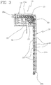
- the moving means 13 comprises at least one pusher 14, which is movable along a substantially vertical direction so that it can be positioned relative to the selected product 5a ( Figure 3 ), as better detailed hereinafter. In this way, the pusher 14 can extract the selected product 5a from the storage 4.
- the vending machine 1 comprises two pushers 14, each associated with a corresponding shelving 8 of the storage 4.
- the pushers 14 are positioned in a rear area of the inner compartment 3. In other words, the pushers 14 are located behind the storage 4 with respect to the window 7.
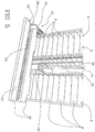
- the moving means 13 comprises a lifting table 15 movable along a substantially vertical direction in order to receive the selected product 5a which was expelled from the storage 4 by the pusher 14 ( Figure 5 ).
- the lifting table 15 is aligned to the shelf 9 corresponding to the selected product 5a so that the latter, pushed by the pusher 14, slides on the lifting table 15. Subsequently, the lifting table 15 transfers the selected product 5a in the vicinity of the collecting compartment 10.
- the lifting table 15 is rigidly associated to the pusher 14 so as to be moved simultaneously with the latter.
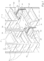
- the latter comprise a respective chain 16 having a first free end 16a, which is movable along a direction parallel to the shelves 9 of the storage 4, and a second free end 16b, movable along a substantially vertical direction.
- the first free end 16a of the chain 16 is intended to come into contact with the selected product 5a in order to push the latter from an inner position to an outer position to the storage 4.
- the chain 16 comprises a first portion 17a lying substantially horizontal, and a second portion 17b lying loosely under the action of its own weight.
- This first portion 17a comprises the aforementioned first free end 16a, whilst the second portion 17b comprises the aforementioned second free end 16b.
- the chain 16 comprises a plurality of meshes 18, each engaged to the other in a known manner.
- An essential characteristic of the above mentioned chain 16 is to be flexible on one side only, in the depicted example of embodiment, the one facing downwards. The flexibility on the part of the side facing upwards, is prevented mechanically by fasteners that do not allow the relative rotation of the meshes.
- a stiffening block 19 is associated with each mesh 18.
- the stiffening blocks 19 allow the chain 16 to bend to one side only, so that the concavity thereof is facing only a zone opposite to the one wherein the stiffening blocks 19 are lying.
- Each pusher 14 further comprises a movable support body 20 that is associated with the lifting table 15.
- a guide 21 which assists and promotes sliding of the chain 16.
- the guide 21 promotes and assists sliding of the first portion 17a of the chain 16.
- Each support body 20 is associated with a respective actuating member 22 of the chain 16.
- the actuating member 22 comprises a toothed wheel 23, rotatably mounted on the support body 20, which meshes with the chain 16 for moving the latter, and a motor 24 connected to the toothed wheel 23 and associated to the support body 20.
- Each pusher 14 further comprises a respective fixed panel 25, with a substantially vertical orientation to the first free end 16a of the chain 16. This panel is interposed between the first free end 16a of the chain 16 and the selected product 5a.
- the motor 24 sets in rotation the toothed wheel 23.
- the toothed wheel 23 drives the chain 16, such as to cause the first free end 16a to advance, which first free end 16a, after having come into contact with the selected product 5a, pushes the latter onto the lifting table 15.
- the lifting table 15 comprises two separate flat potions 26 placed alongside one to another.
- the flat portions 26 are coplanar so as to define a single supporting plane 27 for the selected product 5a which was expelled from the storage 4.
- the lifting table 15 further comprises a transfer member 28 having the function to translate the selected product along a major extension direction of the lifting table 15 itself.
- the transfer member 28 is required for bringing the selected product 5a closer to the collecting compartment 10.
- the transfer member 28 comprises a conveyor belt 29 arranged parallel to the direction of development of the lifting table 15 and a lug 30 secured to the conveyor belt 29 and capable of coming into contact with the selected product 5a so as to move the latter.
- the transfer member 28 is disposed between the separate flat portions 26 of the lifting table 15, such that the lug 30 is protruding, thereby intercepting the selected product 5a which is resting on the supporting plane 27 of the lifting table 15.
- each pusher 14 is rigidly associated with the lifting table 15 such that the pushers 14 can move solidly and simultaneously.
- the moving means 13 comprises a straight guide 31, substantially vertical, and a carriage 32 being slidable along the straight guide 31.
- the straight guide 31 comprises a pair of vertical and parallel bars 33 and is placed between the two shelving 8 of the storage 4.
- the carriage 32 is associated with each pusher 14.
- the carriage 32 is further associated with the lifting table 15.
- the moving means 13 also comprises an arm 34 arranged transversely to the straight guide 31 and connected to the support body 20 of each pusher 14.
- the arm 34 exhibit an "L"-shaped cross-section.
- the moving means 13 further comprises a motor 35 to put in motion the carriage 32. More in detail, the motor 35 is connected to the carriage 32 by a pair of toothed belts 36 set in rotation by the motor 35 and secured to the carriage 32.
- the actuation of the motor 35 determines the upward and downward movement of the carriage 32 and with it, that of the pushers 14 and of the lifting table15.
- the motor 35 of the moving means 13 is actuated in order to allow the pusher 14 to reach the shelf whereon the selected product 5a is placed.
- the motor 24 of the pusher 14 is actuated relative to which the selected product 5a is located.
- the toothed wheel 23 drives the chain 16 such that the first free end 16a comes closer to the selected product 5a, intercepts it and finally push it onto the lifting table 15.
- the carriage 32 is lowered to allow the lifting table 15 to reach the opening 11 which puts in communication the inner compartment 3 with the collecting compartment 10.
- the transfer member 28 is then activated for moving the selected product 5a towards the communication opening 11.
- the door 12 is opened and the selected product 5a transferred from the inner compartment 3 to the collecting compartment 10.
- the door 12 is then closed right after again in order that the thermal insulation of the inner compartment 3 is reset.
- the selection means 37 comprises a selection button (not shown), which is placed on the front wall 6 in proximity of each product 5.
- the selection means 37 comprises an alphanumeric keyboard 38.
- the distributing machine 1 further comprises a control unit for acquiring at least a first signal indicative of the selected product 5a from the selection means 37, and sending to the moving means 13 at least one second signal indicative of the position of the selected product 5a in the storage 4.
- This second signal is conveyed by a suitable power supply and control device (not shown in the figures), associated with the moving means 13.
- a power supply and control device feeds the second signal to the moving means 13, in order to activate the motor 35 of the moving means 13 and the motor 24 of the suitable pusher 14 for transferring the selected product 5a into the collecting compartment 10.
- the power supply and control device in addition to transferring said second signal, also feeds to aforementioned motors 24, 35 with the electric power necessary to the activation of the same.
- the power supply and control device comprises a flexible printed circuit. Not being provided any metal parts, in this manner the harmful effects of a prolonged exposure of the power supply and control device at very low temperatures can be obviated indeed.
- the vending machine 1 further comprises an identification device 39, 40 of the products 5, which is connected to the control unit of the machine so that each product can be associated with a corresponding information relating to its position in the storage.
- the identification device 39,40 comprises a bar code reader 39.
- the identification device 39,40 comprises two readers 39, each one associated to the support body 20 of a respective pusher 14.
- the identification device 39, 40 further includes a proximity sensor 40 that is arranged for detecting the presence of at least one product 5 on the shelves 9.
- each reader 39 is disposed in the vicinity of a side of the shelves 9, preferably the side of the shelves 9 toward which a bar code, applied on a side of the products 5, is pointing.
- each reader 39 is arranged parallel to one side of the shelves 9, which side is facing the other shelves 9 column 8 of the storage 4.
- the identification device provided with two readers 39 is placed within the space between the two columns 8 of the shelves 9.
- the identification device 39,40 is movable vertically, so as to be aligned to each shelf 9.
- the identification device 39,40 allows to considerably simplify the filling operations of the distributing machine 1.
- the moving means 13 move the support bodies 20 to which the readers 39 and the proximity sensors 40 are associated, so that a scan of the products 5, and relative position thereof within the storage 4, can be effected.
- the proximity sensor 40 detects the presence of a product 5. If a product 5 is actually present on the shelf 9, then the reader 39 performs reading of the bar code thereof, wherein the position and the identification code of the product 5 are communicated to the control unit of the storage.
- the position of the reader 39 parallel to a side of the shelves 9, makes the reading of the bar codes applied on the corresponding side of the products 5 substantially foolproof, and this also applies in case of inclined surfaces of the products themselves. It is sufficient that the products 5 are placed into the storage 4 and made to rest on respective shelves 9, in such a manner that the barcodes are facing the side of the shelf 9 toward which the barcode reader 39 is pointing.
- each product 5 may always be associated to the respective location, such that the selected product 5a is promptly identified, irrespective of its location.
- the invention attains the intended purposes and achieves important advantages.
- the vending machine 1 according to the present invention is remarkably impactful on the energy-saving efficiency indeed, in that the pusher 14 disclosed herein, enable to considerably reduce the inner space. This allows to reduce the volume of the inner compartment 3 thereby also reducing the energy quantity required to cool such volume and to keep constant the temperature inside the inner compartment 3, in order to ensure the correct preservation of the products 5 contained therein.
- the machine can advantageously be provided with one or more heating or cooking furnaces 100, only shown schematically in Figure 1 .
- Said one or more furnaces 100 can be placed by side of the storage 4 (for example on the right side of the machine as depicted in figure 1 ), i.e. by side of the shelving 8.
- the furnace 100 are preferably placed above the collecting compartment 10.
- Each furnace 100 exhibits an access door which opens outwards the machine.
- Each furnace is instead isolated relative to the interior of the machine, in particular relative to the storage 4. In this manner any substantial increase in the temperature of the storage 4 is generated by the furnace 100.
- the furnaces 100 may be provided with an automatic door (not shown in detail), that is predisposed for being opened and closed only under pre-determined circumstances.
- the door of each furnace 100 may be provided with an opening and closing mechanism connected to the control unit of the machine.
- the control unit sends an opening command to the opening and closing mechanism of a door only after that a product has been picked up, for example by typing the corresponding code on the alphanumeric keyboard of the machine.
- the control unit sets the cooking/heating time of the product. After that the cooking/heating cycle is terminated, the control unit sends a command for opening the door so that the product can be picked up and the door of the used furnace closed again.
Landscapes
- Physics & Mathematics (AREA)
- General Physics & Mathematics (AREA)
- Vending Machines For Individual Products (AREA)
- Control Of Vending Devices And Auxiliary Devices For Vending Devices (AREA)
Claims (14)
- Verkaufsautomat für Produkte, umfassend:- eine Lagerstruktur (2), die ein Innenfach (3) definiert;- mindestens einen Speicher (4), der innerhalb des Innenfachs (3) angeordnet ist und eine Vielzahl an Regalen (9) umfasst, auf denen die Produkte (5) aufgestellt sind;- ein Sammelfach (10) zum Aufnehmen eines ausgewählten Produkts (5a);- Bewegungsmittel (13) des ausgewählten Produkts (5a), die angeordnet sind, um das ausgewählte Produkt (5a) vom Speicher (4) zum Sammelfach (10) zu bewegen, wobei die Bewegungsmittel (13) mindestens einen Drücker (14) umfassen, der relativ zu dem ausgewählten Produkt (5a) positionierbar ist, so dass das ausgewählte Produkt (5a) aus dem Speicher (4) extrahiert werden kann;- mindestens eine Identifikationsvorrichtung (39,40) der Produkte (5), die eingerichtet ist, um einem jeden Produkt eine entsprechende Information in Bezug auf die Position, die dieses im Speicher einnimmt, zuzuordnen, wobei die Identifikationsvorrichtung (39,40) mindestens einen Barcodeleser (39) umfasst;der Barcodeleser (39) ist in der Nähe einer Seite der Regale (9) angeordnet, auf die ein auf die Produkte aufgebrachter Barcode (5) zeigt;
dadurch gekennzeichnet, dass
die Identifikationsvorrichtung mindestens einen Näherungssensor (40) umfasst, der zum Erfassen des Vorhandenseins eines Produkts (5) in einem Regal (9) angeordnet ist. - Verkaufsautomat nach Anspruch 1, umfassend zwei Säulen (8) von Regalen (9), die nebeneinander angeordnet sind, wobei die Identifikationsvorrichtung zwei Barcodeleser (39) umfasst, von denen ein jeder parallel zu einer Seite der Regale (9) angeordnet ist, welche Seite der anderen Säule (8) der Regale (9) zugewandt ist.
- Verkaufsautomat nach Anspruch 1, wobei der Drücker (14) eine Kette (16) aufweisend dessen erstes freies Ende (16a), das entlang einer Richtung parallel zu den Regalen (9) beweglich ist, um das ausgewählte Produkt (5a) von einer inneren Position zu einer äußeren Position relativ zu dem Speicher (4) zu drücken und ein zweites freies Ende (16b) umfasst, das entlang einer im Wesentlichen vertikalen Richtung beweglich ist, wobei die Kette (16) einen ersten Abschnitt (17a) im Wesentlichen horizontal und einen zweiten Abschnitt (17b), der entlang einer im Wesentlichen vertikalen Richtung liegt, umfasst.
- Verkaufsautomat nach Anspruch 3, dadurch gekennzeichnet, dass die Kette (16) eine Vielzahl an miteinander verbundenen Maschen (18) und mindestens einen mit einer jeden Maschen (18) assoziierten Versteifungsblock (19) umfasst.
- Verkaufsautomat nach Anspruch 4, dadurch gekennzeichnet, dass der Drücker (14) einen Tragkörper (20) umfasst, der beweglich ist, um relativ zu dem ausgewählten Produkt (5a) positioniert zu werden; wobei der Tragkörper (20) eine Gleitführung (21) der Kette (16) zum Tragen des ersten Abschnitts (17a) der Kette (16) umfasst.
- Maschine nach einem der vorhergehenden Ansprüche, dadurch gekennzeichnet, dass die Bewegungsmittel (13) ferner einen Hebetisch (15) zum Aufnehmen des ausgewählten Produkts (5a) umfassen, der aus dem Speicher (4) nach außen gedrückt wurde; wobei der Hebetisch (15) das ausgewählte Produkt (5a) bis in die Nähe des Sammelfachs (10) hebt.
- Verkaufsautomat nach Anspruch 6, dadurch gekennzeichnet, dass der Hebetisch (15) mit dem Drücker (14) assoziiert ist, um sich gleichzeitig mit diesem zu bewegen.
- Verkaufsautomat nach Anspruch 6 oder 7, dadurch gekennzeichnet, dass der Hebetisch (15) ein Transferelement (28) zum Verschieben des ausgewählten Produkts (5a) entlang einer Hauptausdehnungsrichtung des Hebetisches (15) selbst umfasst, um das ausgewählte Produkt (5a) in das Sammelfach (10) zu bewegen.
- Verkaufsautomat nach einem der vorhergehenden Ansprüche, dadurch gekennzeichnet, dass die Bewegungsmittel (13) eine im Wesentlichen vertikale gerade Führung (31) und einen Schlitten (32) umfassen, der entlang der geraden Führung (31) gleitet; wobei der Schlitten (32) mindestens mit dem Drücker (14) assoziiert ist.
- Verkaufsautomat nach einem der vorhergehenden Ansprüche, dadurch gekennzeichnet, dass die Bewegungsmittel (13) eine im Wesentlichen vertikale gerade Führung (31) und einen Schlitten (32) umfassen, der entlang der geraden Führung (31) gleitet; wobei der Schlitten (32) mindestens mit dem Hebetisch (15) assoziiert ist.
- Verkaufsautomat nach einem der vorhergehenden Ansprüche, dadurch gekennzeichnet, dass er Auswahlmittel (37), um es einem Benutzer zu ermöglichen, ein Produkt auszuwählen, und eine Steuereinheit umfasst, um durch die Auswahlmittel (37) ein erstes Signal zu erfassen, das indikativ für das ausgewählte Produkt ist, und um an die Bewegungsmittel (13) mindestens ein zweites Signal zu senden, das für die Position des ausgewählten Produkts (5a) im Speicher (4) indikativ ist.
- Verkaufsautomat nach Anspruch 11, dadurch gekennzeichnet, dass er eine Identifikationsvorrichtung (39) der Produkte (5) umfasst, um mit einem jeden Produkt (5) eine entsprechende Information über den Ort des letzteren innerhalb des Speichers zu assoziieren.
- Verkaufsautomat nach Anspruch 11, dadurch gekennzeichnet, dass die Identifikationsvorrichtung (39,40) der Produkte zwei Barcodeleser (40) umfasst.
- Verkaufsautomat nach einem der vorhergehenden Ansprüche, umfassend einen oder mehrere Öfen (100), die neben dem Speicher (4) angeordnet sind.
Applications Claiming Priority (1)
| Application Number | Priority Date | Filing Date | Title |
|---|---|---|---|
| PCT/IT2016/000138 WO2017203546A1 (en) | 2016-05-27 | 2016-05-27 | Vending machine of products |
Publications (2)
| Publication Number | Publication Date |
|---|---|
| EP3465641A1 EP3465641A1 (de) | 2019-04-10 |
| EP3465641B1 true EP3465641B1 (de) | 2020-12-02 |
Family
ID=56609885
Family Applications (1)
| Application Number | Title | Priority Date | Filing Date |
|---|---|---|---|
| EP16747913.8A Active EP3465641B1 (de) | 2016-05-27 | 2016-05-27 | Verkaufsautomat für produkte |
Country Status (3)
| Country | Link |
|---|---|
| EP (1) | EP3465641B1 (de) |
| ES (1) | ES2842775T3 (de) |
| WO (1) | WO2017203546A1 (de) |
Families Citing this family (8)
| Publication number | Priority date | Publication date | Assignee | Title |
|---|---|---|---|---|
| US10176469B2 (en) * | 2016-12-21 | 2019-01-08 | Bezalel's Jewelry Inc. | Interactive jewelry vending machine |
| CN108205844B (zh) * | 2017-12-15 | 2023-12-26 | 成都越凡创新科技有限公司 | 提升机构链条储存槽的安装结构以及提升机构 |
| CN110910570A (zh) * | 2018-09-18 | 2020-03-24 | 威海新北洋数码科技有限公司 | 货道配置方法、自动售货机及移动终端 |
| CN109903461B (zh) * | 2019-01-24 | 2020-12-01 | 浙江机电职业技术学院 | 自动快餐贩卖机 |
| US10803783B2 (en) * | 2019-01-31 | 2020-10-13 | Dynascan Technology Corp. | Electronic shelf display apparatus |
| CN109979080A (zh) * | 2019-03-15 | 2019-07-05 | 安徽智佳信息科技有限公司 | 一种办公楼用智能自助售货管理系统 |
| ES2953201B2 (es) * | 2022-03-28 | 2024-03-18 | Zedis S L | Mueble de almacenamiento y dispensacion de productos |
| CZ36212U1 (cs) | 2022-06-14 | 2022-07-12 | ROBOTERM spol.s r.o | Zařízení pro vytlačování polotovarů |
Family Cites Families (3)
| Publication number | Priority date | Publication date | Assignee | Title |
|---|---|---|---|---|
| US5221023A (en) * | 1988-10-10 | 1993-06-22 | Dubik Andre S | Process and apparatus for the automatic dispensing of products, especially of food products, if necessary reheated |
| ITVI20050199A1 (it) * | 2005-07-18 | 2007-01-19 | Daint Srl | Distributore automatico |
| ITMO20070346A1 (it) * | 2007-11-16 | 2009-05-17 | Giuseppe Biffarella | Macchina distributrice di prodotti. |
-
2016
- 2016-05-27 EP EP16747913.8A patent/EP3465641B1/de active Active
- 2016-05-27 WO PCT/IT2016/000138 patent/WO2017203546A1/en not_active Ceased
- 2016-05-27 ES ES16747913T patent/ES2842775T3/es active Active
Non-Patent Citations (1)
| Title |
|---|
| None * |
Also Published As
| Publication number | Publication date |
|---|---|
| ES2842775T3 (es) | 2021-07-14 |
| WO2017203546A1 (en) | 2017-11-30 |
| EP3465641A1 (de) | 2019-04-10 |
Similar Documents
| Publication | Publication Date | Title |
|---|---|---|
| EP3465641A1 (de) | Verkaufsautomat für produkte | |
| US4687119A (en) | Dispenser for hot and cold products | |
| CN107945389B (zh) | 一种自动售卖柜及售货方法 | |
| CN110111493B (zh) | 一种盒饭自助售卖机 | |
| US7137529B2 (en) | Apparatus and method for distributing warm prepackaged foods | |
| JP2012127647A (ja) | 収納庫及び冷蔵庫 | |
| HRP20181907T1 (hr) | Sustavi i postupci za proizvodnju prehrambenih proizvoda | |
| CN107195121A (zh) | 冷藏保温及预售的自动食品售卖机 | |
| EP2061011A2 (de) | Produktverkaufsautomat | |
| CN109685977A (zh) | 一种微波加热自动售货机 | |
| KR100653237B1 (ko) | 자판식 즉석피자 자동제조 장치 | |
| CN211224983U (zh) | 一种自动货柜 | |
| CN112471828A (zh) | 一种智能变温储藏柜 | |
| CN217690185U (zh) | 售货机 | |
| CN111899415A (zh) | 一种高效自动取餐机及取餐方法 | |
| CN109949493A (zh) | 基于双面齿同步带推板的出货机构、售货机及出货方法 | |
| KR101058272B1 (ko) | 자동 판매기 | |
| KR20090073320A (ko) | 인스턴트피자 자동판매기 | |
| CN204883945U (zh) | 自动售卖机 | |
| CN206877429U (zh) | 一种可冷藏保温及预售的自动食品售卖机 | |
| RU2751827C1 (ru) | Торговый автомат для продажи разогретых продуктов питания | |
| JPH09147223A (ja) | 自動販売機 | |
| CN208922385U (zh) | 一种回转式结构货架及其构成的自动售货机 | |
| KR101135754B1 (ko) | 자동판매기 | |
| CN110107929B (zh) | 用于盒饭自动售卖机的微波加热系统 |
Legal Events
| Date | Code | Title | Description |
|---|---|---|---|
| STAA | Information on the status of an ep patent application or granted ep patent |
Free format text: STATUS: THE INTERNATIONAL PUBLICATION HAS BEEN MADE |
|
| PUAI | Public reference made under article 153(3) epc to a published international application that has entered the european phase |
Free format text: ORIGINAL CODE: 0009012 |
|
| STAA | Information on the status of an ep patent application or granted ep patent |
Free format text: STATUS: REQUEST FOR EXAMINATION WAS MADE |
|
| 17P | Request for examination filed |
Effective date: 20181128 |
|
| AK | Designated contracting states |
Kind code of ref document: A1 Designated state(s): AL AT BE BG CH CY CZ DE DK EE ES FI FR GB GR HR HU IE IS IT LI LT LU LV MC MK MT NL NO PL PT RO RS SE SI SK SM TR |
|
| AX | Request for extension of the european patent |
Extension state: BA ME |
|
| DAV | Request for validation of the european patent (deleted) | ||
| DAX | Request for extension of the european patent (deleted) | ||
| STAA | Information on the status of an ep patent application or granted ep patent |
Free format text: STATUS: EXAMINATION IS IN PROGRESS |
|
| 17Q | First examination report despatched |
Effective date: 20191002 |
|
| GRAP | Despatch of communication of intention to grant a patent |
Free format text: ORIGINAL CODE: EPIDOSNIGR1 |
|
| STAA | Information on the status of an ep patent application or granted ep patent |
Free format text: STATUS: GRANT OF PATENT IS INTENDED |
|
| GRAJ | Information related to disapproval of communication of intention to grant by the applicant or resumption of examination proceedings by the epo deleted |
Free format text: ORIGINAL CODE: EPIDOSDIGR1 |
|
| INTG | Intention to grant announced |
Effective date: 20200526 |
|
| STAA | Information on the status of an ep patent application or granted ep patent |
Free format text: STATUS: EXAMINATION IS IN PROGRESS |
|
| INTC | Intention to grant announced (deleted) | ||
| GRAP | Despatch of communication of intention to grant a patent |
Free format text: ORIGINAL CODE: EPIDOSNIGR1 |
|
| STAA | Information on the status of an ep patent application or granted ep patent |
Free format text: STATUS: GRANT OF PATENT IS INTENDED |
|
| INTG | Intention to grant announced |
Effective date: 20200922 |
|
| GRAS | Grant fee paid |
Free format text: ORIGINAL CODE: EPIDOSNIGR3 |
|
| GRAA | (expected) grant |
Free format text: ORIGINAL CODE: 0009210 |
|
| STAA | Information on the status of an ep patent application or granted ep patent |
Free format text: STATUS: THE PATENT HAS BEEN GRANTED |
|
| AK | Designated contracting states |
Kind code of ref document: B1 Designated state(s): AL AT BE BG CH CY CZ DE DK EE ES FI FR GB GR HR HU IE IS IT LI LT LU LV MC MK MT NL NO PL PT RO RS SE SI SK SM TR |
|
| REG | Reference to a national code |
Ref country code: GB Ref legal event code: FG4D |
|
| REG | Reference to a national code |
Ref country code: AT Ref legal event code: REF Ref document number: 1341772 Country of ref document: AT Kind code of ref document: T Effective date: 20201215 Ref country code: CH Ref legal event code: EP |
|
| REG | Reference to a national code |
Ref country code: DE Ref legal event code: R096 Ref document number: 602016049033 Country of ref document: DE |
|
| REG | Reference to a national code |
Ref country code: IE Ref legal event code: FG4D |
|
| PG25 | Lapsed in a contracting state [announced via postgrant information from national office to epo] |
Ref country code: GR Free format text: LAPSE BECAUSE OF FAILURE TO SUBMIT A TRANSLATION OF THE DESCRIPTION OR TO PAY THE FEE WITHIN THE PRESCRIBED TIME-LIMIT Effective date: 20210303 Ref country code: FI Free format text: LAPSE BECAUSE OF FAILURE TO SUBMIT A TRANSLATION OF THE DESCRIPTION OR TO PAY THE FEE WITHIN THE PRESCRIBED TIME-LIMIT Effective date: 20201202 Ref country code: RS Free format text: LAPSE BECAUSE OF FAILURE TO SUBMIT A TRANSLATION OF THE DESCRIPTION OR TO PAY THE FEE WITHIN THE PRESCRIBED TIME-LIMIT Effective date: 20201202 Ref country code: NO Free format text: LAPSE BECAUSE OF FAILURE TO SUBMIT A TRANSLATION OF THE DESCRIPTION OR TO PAY THE FEE WITHIN THE PRESCRIBED TIME-LIMIT Effective date: 20210302 |
|
| REG | Reference to a national code |
Ref country code: NL Ref legal event code: MP Effective date: 20201202 |
|
| REG | Reference to a national code |
Ref country code: AT Ref legal event code: MK05 Ref document number: 1341772 Country of ref document: AT Kind code of ref document: T Effective date: 20201202 |
|
| PG25 | Lapsed in a contracting state [announced via postgrant information from national office to epo] |
Ref country code: SE Free format text: LAPSE BECAUSE OF FAILURE TO SUBMIT A TRANSLATION OF THE DESCRIPTION OR TO PAY THE FEE WITHIN THE PRESCRIBED TIME-LIMIT Effective date: 20201202 Ref country code: BG Free format text: LAPSE BECAUSE OF FAILURE TO SUBMIT A TRANSLATION OF THE DESCRIPTION OR TO PAY THE FEE WITHIN THE PRESCRIBED TIME-LIMIT Effective date: 20210302 Ref country code: PL Free format text: LAPSE BECAUSE OF FAILURE TO SUBMIT A TRANSLATION OF THE DESCRIPTION OR TO PAY THE FEE WITHIN THE PRESCRIBED TIME-LIMIT Effective date: 20201202 Ref country code: LV Free format text: LAPSE BECAUSE OF FAILURE TO SUBMIT A TRANSLATION OF THE DESCRIPTION OR TO PAY THE FEE WITHIN THE PRESCRIBED TIME-LIMIT Effective date: 20201202 |
|
| PG25 | Lapsed in a contracting state [announced via postgrant information from national office to epo] |
Ref country code: NL Free format text: LAPSE BECAUSE OF FAILURE TO SUBMIT A TRANSLATION OF THE DESCRIPTION OR TO PAY THE FEE WITHIN THE PRESCRIBED TIME-LIMIT Effective date: 20201202 Ref country code: HR Free format text: LAPSE BECAUSE OF FAILURE TO SUBMIT A TRANSLATION OF THE DESCRIPTION OR TO PAY THE FEE WITHIN THE PRESCRIBED TIME-LIMIT Effective date: 20201202 |
|
| REG | Reference to a national code |
Ref country code: LT Ref legal event code: MG9D |
|
| REG | Reference to a national code |
Ref country code: ES Ref legal event code: FG2A Ref document number: 2842775 Country of ref document: ES Kind code of ref document: T3 Effective date: 20210714 |
|
| PG25 | Lapsed in a contracting state [announced via postgrant information from national office to epo] |
Ref country code: PT Free format text: LAPSE BECAUSE OF FAILURE TO SUBMIT A TRANSLATION OF THE DESCRIPTION OR TO PAY THE FEE WITHIN THE PRESCRIBED TIME-LIMIT Effective date: 20210405 Ref country code: SK Free format text: LAPSE BECAUSE OF FAILURE TO SUBMIT A TRANSLATION OF THE DESCRIPTION OR TO PAY THE FEE WITHIN THE PRESCRIBED TIME-LIMIT Effective date: 20201202 Ref country code: RO Free format text: LAPSE BECAUSE OF FAILURE TO SUBMIT A TRANSLATION OF THE DESCRIPTION OR TO PAY THE FEE WITHIN THE PRESCRIBED TIME-LIMIT Effective date: 20201202 Ref country code: CZ Free format text: LAPSE BECAUSE OF FAILURE TO SUBMIT A TRANSLATION OF THE DESCRIPTION OR TO PAY THE FEE WITHIN THE PRESCRIBED TIME-LIMIT Effective date: 20201202 Ref country code: EE Free format text: LAPSE BECAUSE OF FAILURE TO SUBMIT A TRANSLATION OF THE DESCRIPTION OR TO PAY THE FEE WITHIN THE PRESCRIBED TIME-LIMIT Effective date: 20201202 Ref country code: SM Free format text: LAPSE BECAUSE OF FAILURE TO SUBMIT A TRANSLATION OF THE DESCRIPTION OR TO PAY THE FEE WITHIN THE PRESCRIBED TIME-LIMIT Effective date: 20201202 Ref country code: LT Free format text: LAPSE BECAUSE OF FAILURE TO SUBMIT A TRANSLATION OF THE DESCRIPTION OR TO PAY THE FEE WITHIN THE PRESCRIBED TIME-LIMIT Effective date: 20201202 |
|
| PG25 | Lapsed in a contracting state [announced via postgrant information from national office to epo] |
Ref country code: AT Free format text: LAPSE BECAUSE OF FAILURE TO SUBMIT A TRANSLATION OF THE DESCRIPTION OR TO PAY THE FEE WITHIN THE PRESCRIBED TIME-LIMIT Effective date: 20201202 |
|
| REG | Reference to a national code |
Ref country code: DE Ref legal event code: R097 Ref document number: 602016049033 Country of ref document: DE |
|
| PG25 | Lapsed in a contracting state [announced via postgrant information from national office to epo] |
Ref country code: IS Free format text: LAPSE BECAUSE OF FAILURE TO SUBMIT A TRANSLATION OF THE DESCRIPTION OR TO PAY THE FEE WITHIN THE PRESCRIBED TIME-LIMIT Effective date: 20210402 |
|
| PLBE | No opposition filed within time limit |
Free format text: ORIGINAL CODE: 0009261 |
|
| STAA | Information on the status of an ep patent application or granted ep patent |
Free format text: STATUS: NO OPPOSITION FILED WITHIN TIME LIMIT |
|
| PG25 | Lapsed in a contracting state [announced via postgrant information from national office to epo] |
Ref country code: IT Free format text: LAPSE BECAUSE OF FAILURE TO SUBMIT A TRANSLATION OF THE DESCRIPTION OR TO PAY THE FEE WITHIN THE PRESCRIBED TIME-LIMIT Effective date: 20201202 Ref country code: AL Free format text: LAPSE BECAUSE OF FAILURE TO SUBMIT A TRANSLATION OF THE DESCRIPTION OR TO PAY THE FEE WITHIN THE PRESCRIBED TIME-LIMIT Effective date: 20201202 |
|
| 26N | No opposition filed |
Effective date: 20210903 |
|
| PG25 | Lapsed in a contracting state [announced via postgrant information from national office to epo] |
Ref country code: DK Free format text: LAPSE BECAUSE OF FAILURE TO SUBMIT A TRANSLATION OF THE DESCRIPTION OR TO PAY THE FEE WITHIN THE PRESCRIBED TIME-LIMIT Effective date: 20201202 Ref country code: SI Free format text: LAPSE BECAUSE OF FAILURE TO SUBMIT A TRANSLATION OF THE DESCRIPTION OR TO PAY THE FEE WITHIN THE PRESCRIBED TIME-LIMIT Effective date: 20201202 |
|
| REG | Reference to a national code |
Ref country code: CH Ref legal event code: PL |
|
| GBPC | Gb: european patent ceased through non-payment of renewal fee |
Effective date: 20210527 |
|
| PG25 | Lapsed in a contracting state [announced via postgrant information from national office to epo] |
Ref country code: CH Free format text: LAPSE BECAUSE OF NON-PAYMENT OF DUE FEES Effective date: 20210531 Ref country code: LU Free format text: LAPSE BECAUSE OF NON-PAYMENT OF DUE FEES Effective date: 20210527 Ref country code: MC Free format text: LAPSE BECAUSE OF FAILURE TO SUBMIT A TRANSLATION OF THE DESCRIPTION OR TO PAY THE FEE WITHIN THE PRESCRIBED TIME-LIMIT Effective date: 20201202 Ref country code: LI Free format text: LAPSE BECAUSE OF NON-PAYMENT OF DUE FEES Effective date: 20210531 |
|
| REG | Reference to a national code |
Ref country code: BE Ref legal event code: MM Effective date: 20210531 |
|
| PG25 | Lapsed in a contracting state [announced via postgrant information from national office to epo] |
Ref country code: IE Free format text: LAPSE BECAUSE OF NON-PAYMENT OF DUE FEES Effective date: 20210527 Ref country code: GB Free format text: LAPSE BECAUSE OF NON-PAYMENT OF DUE FEES Effective date: 20210527 |
|
| PG25 | Lapsed in a contracting state [announced via postgrant information from national office to epo] |
Ref country code: IS Free format text: LAPSE BECAUSE OF FAILURE TO SUBMIT A TRANSLATION OF THE DESCRIPTION OR TO PAY THE FEE WITHIN THE PRESCRIBED TIME-LIMIT Effective date: 20210402 |
|
| PG25 | Lapsed in a contracting state [announced via postgrant information from national office to epo] |
Ref country code: BE Free format text: LAPSE BECAUSE OF NON-PAYMENT OF DUE FEES Effective date: 20210531 |
|
| PG25 | Lapsed in a contracting state [announced via postgrant information from national office to epo] |
Ref country code: CY Free format text: LAPSE BECAUSE OF FAILURE TO SUBMIT A TRANSLATION OF THE DESCRIPTION OR TO PAY THE FEE WITHIN THE PRESCRIBED TIME-LIMIT Effective date: 20201202 |
|
| PG25 | Lapsed in a contracting state [announced via postgrant information from national office to epo] |
Ref country code: HU Free format text: LAPSE BECAUSE OF FAILURE TO SUBMIT A TRANSLATION OF THE DESCRIPTION OR TO PAY THE FEE WITHIN THE PRESCRIBED TIME-LIMIT; INVALID AB INITIO Effective date: 20160527 |
|
| PG25 | Lapsed in a contracting state [announced via postgrant information from national office to epo] |
Ref country code: MK Free format text: LAPSE BECAUSE OF FAILURE TO SUBMIT A TRANSLATION OF THE DESCRIPTION OR TO PAY THE FEE WITHIN THE PRESCRIBED TIME-LIMIT Effective date: 20201202 |
|
| PGFP | Annual fee paid to national office [announced via postgrant information from national office to epo] |
Ref country code: DE Payment date: 20240529 Year of fee payment: 9 |
|
| PGFP | Annual fee paid to national office [announced via postgrant information from national office to epo] |
Ref country code: ES Payment date: 20240610 Year of fee payment: 9 |
|
| PGFP | Annual fee paid to national office [announced via postgrant information from national office to epo] |
Ref country code: FR Payment date: 20240529 Year of fee payment: 9 |
|
| PG25 | Lapsed in a contracting state [announced via postgrant information from national office to epo] |
Ref country code: MT Free format text: LAPSE BECAUSE OF FAILURE TO SUBMIT A TRANSLATION OF THE DESCRIPTION OR TO PAY THE FEE WITHIN THE PRESCRIBED TIME-LIMIT Effective date: 20201202 |
|
| REG | Reference to a national code |
Ref country code: DE Ref legal event code: R119 Ref document number: 602016049033 Country of ref document: DE |
|
| PG25 | Lapsed in a contracting state [announced via postgrant information from national office to epo] |
Ref country code: TR Free format text: LAPSE BECAUSE OF FAILURE TO SUBMIT A TRANSLATION OF THE DESCRIPTION OR TO PAY THE FEE WITHIN THE PRESCRIBED TIME-LIMIT Effective date: 20201202 |
|
| PG25 | Lapsed in a contracting state [announced via postgrant information from national office to epo] |
Ref country code: DE Free format text: LAPSE BECAUSE OF NON-PAYMENT OF DUE FEES Effective date: 20251202 |
|
| PG25 | Lapsed in a contracting state [announced via postgrant information from national office to epo] |
Ref country code: FR Free format text: LAPSE BECAUSE OF NON-PAYMENT OF DUE FEES Effective date: 20250531 |