EP3465386B1 - Trackballs - Google Patents
Trackballs Download PDFInfo
- Publication number
- EP3465386B1 EP3465386B1 EP17730898.8A EP17730898A EP3465386B1 EP 3465386 B1 EP3465386 B1 EP 3465386B1 EP 17730898 A EP17730898 A EP 17730898A EP 3465386 B1 EP3465386 B1 EP 3465386B1
- Authority
- EP
- European Patent Office
- Prior art keywords
- trackball
- ball
- recess
- magnetic
- magnet
- Prior art date
- Legal status (The legal status is an assumption and is not a legal conclusion. Google has not performed a legal analysis and makes no representation as to the accuracy of the status listed.)
- Active
Links
Images


Classifications
-
- G—PHYSICS
- G06—COMPUTING OR CALCULATING; COUNTING
- G06F—ELECTRIC DIGITAL DATA PROCESSING
- G06F3/00—Input arrangements for transferring data to be processed into a form capable of being handled by the computer; Output arrangements for transferring data from processing unit to output unit, e.g. interface arrangements
- G06F3/01—Input arrangements or combined input and output arrangements for interaction between user and computer
- G06F3/03—Arrangements for converting the position or the displacement of a member into a coded form
- G06F3/033—Pointing devices displaced or positioned by the user, e.g. mice, trackballs, pens or joysticks; Accessories therefor
- G06F3/0354—Pointing devices displaced or positioned by the user, e.g. mice, trackballs, pens or joysticks; Accessories therefor with detection of two-dimensional [2D] relative movements between the device, or an operating part thereof, and a plane or surface, e.g. 2D mice, trackballs, pens or pucks
- G06F3/03549—Trackballs
-
- G—PHYSICS
- G06—COMPUTING OR CALCULATING; COUNTING
- G06F—ELECTRIC DIGITAL DATA PROCESSING
- G06F3/00—Input arrangements for transferring data to be processed into a form capable of being handled by the computer; Output arrangements for transferring data from processing unit to output unit, e.g. interface arrangements
- G06F3/01—Input arrangements or combined input and output arrangements for interaction between user and computer
- G06F3/016—Input arrangements with force or tactile feedback as computer generated output to the user
-
- G—PHYSICS
- G06—COMPUTING OR CALCULATING; COUNTING
- G06F—ELECTRIC DIGITAL DATA PROCESSING
- G06F3/00—Input arrangements for transferring data to be processed into a form capable of being handled by the computer; Output arrangements for transferring data from processing unit to output unit, e.g. interface arrangements
- G06F3/01—Input arrangements or combined input and output arrangements for interaction between user and computer
- G06F3/03—Arrangements for converting the position or the displacement of a member into a coded form
- G06F3/033—Pointing devices displaced or positioned by the user, e.g. mice, trackballs, pens or joysticks; Accessories therefor
- G06F3/0354—Pointing devices displaced or positioned by the user, e.g. mice, trackballs, pens or joysticks; Accessories therefor with detection of two-dimensional [2D] relative movements between the device, or an operating part thereof, and a plane or surface, e.g. 2D mice, trackballs, pens or pucks
- G06F3/03541—Mouse/trackball convertible devices, in which the same ball is used to track the 2D relative movement
Definitions
- Trackballs may be arranged for use in a variety of applications and scenarios, such as medical, marine, aerospace and/or defence environments, for providing inputs to a controller.
- Trackballs which are used in such environments may require cleaning of one or more parts of the trackballs.
- a ball, a housing, a bearing element and/or another part of a trackball may need to be wiped, sluiced or sprayed with fluid to remove accumulated dirt, oil, water and/or other substances. This can be particularly important if the trackball is used in medical environments in which the trackball comes into contact with patients or medical practitioners, whose health could be jeopardised if bacteria or viruses, for example, contaminate the trackball.
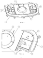
- FIG. 1A and 1B An example of a conventional trackball 11 is illustrated in Figures 1A and 1B .
- the trackball 11 includes a ball 13 and a plurality of buttons 15 that act as mechanical function keys.
- the ball 13 of trackball 11 is retained within a housing of the trackball 11 by a retaining ring 17.
- the retaining ring 17 may control or affect the force a user of the trackball 11 needs to apply to the ball 13 to cause the ball 13 to rotate relative to the housing. This force may be referred to as a "tracking force".
- the retaining ring 17 may be in direct contact with the ball 13 such that there is friction between the retaining ring 17 and the ball 13.
- an intervening component or intervening components such as a ball seal and/or a sponge, may be located between the retaining ring 17 and the ball 13 such that there is friction between a component and the ball 13.
- the magnitude of the friction may affect how easy it is for the user to rotate the ball 13 relative to the housing.
- the retaining ring 17 may be removable (e.g. through a twisting unlocking motion or otherwise) to allow the ball 13 and/or other components to be removed for cleaning.
- the buttons 15 and retaining ring 17 may be positioned adjacent to one another or to other components of the trackball 11. However, this leaves gaps 19 between the ball 13, the buttons 15, the retaining ring 17 and/or other components of the trackball 11.
- the dirt, oil, water and other substances referred to above can accumulate in these gaps.
- the gaps are difficult to clean and therefore present a hygiene risk as well as an opportunity for substances which can damage the trackball 11 to find their way into the trackball 11. Such substances may become trapped underneath the retaining ring 17 and/or underneath the buttons 15.
- EP0520089-A1 discloses a mouse system in which the rolling force of the ball is made adjustable to suit an operator's preference. A friction pad or a magnetic force may be applied to the ball to change and adjust the ball rolling force.
- JP 2011-145724-A discloses an input device which prevents dirt and dust from affecting the resistance feedback.
- a ball supported by a support member and the ball has an internal magnetic body which is attracted to an external magnet which is arranged outside the ball and opposite thereto.
- the internal magnetic body is attracted to the external magnet so that frictional resistance is generated on an internal surface of the ball so that the device is not affected by dirt or dust on the external surface.
- DE 10332614 discloses a ball having magnetic components inside and an electromagnet outside which attracts the magnetic components. This provides magnetic resistance to the rotation of the operating element.
- JP 2004-265188 discloses a trackball in which a rotational operation force necessary for rotation of the ball or the interval or strength of the click, touch can be controlled and thus a stable rotation achieved.
- the ball includes magnetic material which is positioned in the path of a magnetic force line generated by an electromagnet. This creates a friction force between the sphere and a supporting member which is adjustable by adjusting the electromagnet.
- JP 2006-189950 discloses an input apparatus with a rolling element.
- the apparatus has an electromagnet inside a housing an magnetic powder housed inside a hollow ball which is attracted downwardly by the magnetic force of the electromagnet. The ball is thus pressed against a plurality of shafts of supporting bodies which rotate when the ball rolls.
- JP 2001-117715 discloses a touch and force sensitive presentation device having a sphere including a motor inside a housing and held so as to be vibrated and rotated.
- the motor moves in accordance with a touch or force sense signal transmitted from a processor and thus the sphere is vibrated and a touch/force sense is presented.
- WO 00/20959 discloses a pointing device and a touch sensor near a pointing device ball.
- the touch sensor has an annular ring around the ball and the touch sensor is used to activate a switch to provide power to the input mechanism when the user is ready to use the device.
- US 2002/109674 discloses a trackball unit which has a drainpipe connecting a cavity formed inside the case for accommodating the ball to the exterior of the case.
- the trackball comprises at least one bearing element mounted on or forming part of the housing, the at least one bearing element being arranged to support the magnetic Z ball in the recess.
- the at least one bearing element comprises one or more of: a ball bearing element, and a stationary bearing element.
- these features may make the trackball more hygienic to use and easier to clean than conventional trackballs.
- the means, comprising at least one magnet, for urging the magnetic ball to remain in the recess may help to minimise the number of gaps between trackball components in which substances can accumulate.
- said means may take the place of a retaining ring, a seal and/or other components for urging a ball to remain in a trackball recess.
- the absence of a retaining ring or other mechanical means for urging the ball to remain in the recess may make the trackball easier to clean by minimising the number of obstacles to wiping, sluicing or otherwise removing substances from the trackball.
- the trackball may include means for moving the magnet relative to the recess between a first position and a second position so that a distance between the magnet and the magnetic ball is varied.
- this may allow a force experienced by the magnetic ball as a consequence of the magnetic field emanating from the magnet to be controlled or changed.
- the magnet may be a permanent magnet. In other embodiments, the magnet may be an electromagnet. In some embodiments, a plurality of magnets may be provided. The plurality of magnets may all be permanent magnets, may all be electromagnets, or may include at least one permanent magnet and at least one electromagnet. Advantageously, having at least one permanent magnet may help ensure that the magnetic ball remains within the recess even when power to the trackball is unavailable or switched off.
- the means for moving the magnet includes a motor, a solenoid, a rack and pinion, a linear guide, a lever arrangement or a screw thread.
- the trackball additionally includes a capacitive user input device.
- a capacitive user input device may mean that the trackball does not require mechanical buttons. This may reduce the number of places (e.g. gaps between buttons and other components of the trackball) in which dirt, water, oil, etc. can be accumulated and may make cleaning of the trackball easier.
- the magnetic ball includes a magnetic core, a non-magnetic but magnetically permeable outer layer and/or a resin comprising magnetic filings or particles.
- the trackball is arranged to move the magnet in order to provide feedback or information to a user of the trackball via perceptible acceleration of the magnetic ball and/or changes in resistance to movement of the ball which may be sensed by a user's fingers during use.
- the magnet is mounted on the housing in the vicinity of the recess.
- non-mechanical is used to mean without physical contact or without direct contact.
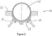
- the trackball 21 includes a magnetic ball 23.
- magnetic means magnetically attractable and/or magnetically repellable, i.e. capable of being attracted and/or repelled by a magnet or accelerated by a magnetic field.
- the magnetic ball 23 comprises a magnetic core 231 and a non-magnetic but magnetically permeable outer layer 235 (see Figure 5 ).
- the magnetic core 231 has a diameter of approximately 50 mm and the non-magnetic, magnetically permeable outer layer 235 has a thickness of approximately 0.4 mm.
- the overall diameter of the illustrated magnetic ball 23 is therefore approximately 50.8 mm.
- the magnetic ball 23 may have different dimensions.
- the magnetic ball 23 may include a resin comprising magnetic filings or particles.
- the ball may not include a non-magnetic outer layer and may be solely a generally homogeneous magnetic core, or may include multiple magnetic layers.
- the magnetic ball 23 may be translucent or transparent while in other embodiments the ball 23 may be opaque.
- the trackball 21 may include a light (such as an LED) to help a user of the trackball 21 see and use the ball 23, e.g. in darkened environments, and/or as a mechanism for providing feedback or information to the user, e.g. by varying the brightness or colour of the light emitted, flashing the light (e.g. in particular patterns), or otherwise varying an output of the light.
- the trackball 21 also includes a housing 25.
- the housing 25 may be formed of any suitable material or materials, such as plastic and/or metal, depending on the intended application of the trackball 21 and/or the environment in which the trackball 21 is intended to be used.
- the housing 25 includes a recess 27 which is arranged to receive at least part of the magnetic ball 23.
- the recess 27 is approximately hemispherical and receives approximately half of the ball 23.
- the recess 27 may be larger, such that it receives a greater proportion of the ball 23, or smaller, such that it receives a lesser proportion of the ball 23.
- the dimensions of the recess 27 may be chosen such that a desired proportion of the ball 23 protrudes above the surface of the housing 25. For instance, in some circumstances, it may be advantageous for the ball 23 to protrude a long way from the recess 27, away from the surface of the housing 25. However, in other circumstances, it may be desirable for the top of the ball 23 to be approximately flush with the surface of the housing 25.
- the recess 27 may include one or more bearing elements arranged to rotatably support the magnetic ball 13, i.e. to support the ball 13 in such a way that it can rotate relative to the housing 25.
- a bearing element might take the form of a curved surface of the recess 27 or a discrete bearing element (such as a ball bearing element, a stationary or fixed-point bearing element e.g. an injection-moulded projection or other protruding feature, or another suitable form of bearing element) located in the recess 27 (e.g. on a surface of the recess 27 or embedded in a surface of the recess 27).
- the bearing element may be any suitable bearing element arranged to support the magnetic ball 23 in such a way that the ball 23 can rotate relative to the housing 25.
- bearing elements may be positioned to achieve particular respective frictional effects on the ball 23.
- the bearing elements may be positioned such that equal frictional forces are applied to the ball 23 at the different bearing elements.
- it may be desired to create a greater frictional force at one or some of the bearing elements, in which the case the bearing elements may be positioned accordingly.
- the recess 27 is designed such that the number of corners, gaps and/or protrusions on the surface of the recess 27 is minimised.
- the recess 27 preferably has a substantially smooth and unbroken surface so that the number of places where substances can accumulate is minimised and the number of obstructions to a cloth or a flow of water across the surface of the recess 27 is minimised.
- the surface of the recess 27 forms an impenetrable barrier which prevents substances from entering the interior of the housing 25 of the trackball 21.
- This and the fact that the non-mechanical means for urging the ball 23 to remain in the recess 27 allows the trackball 21 not to have a conventional retaining ring 17 enables a user of the trackball 21 to clean the trackball 21 conveniently, e.g. by sluicing water, disinfectant and/or another fluid through the recess 27, optionally without removing the ball 23 from the recess 27.
- a drain may be provided in the recess 27 to allow such fluid to exit the recess 27. The drain may be positioned at the lowest point of the recess 27, such that the fluid can drain out of the recess 27 under gravity.
- the trackball 21 additionally includes magnets 29.
- the magnets 29 are mounted on the housing 25 in the vicinity of the recess 27.
- the magnets are mounted on the housing 25 such that magnetic field lines emanating from the magnets 29 enter the recess 27.
- the magnets 29 are arranged such that, when the ball 23 is in the recess 27, the magnets 29 act upon the magnetic ball 23 to urge the magnetic ball 23 to remain in the recess 27.
- the presence of one or more magnets 29 arranged to act upon the magnetic ball 23 to urge the ball 23 to remain in the recess 27 means that trackballs according to embodiments of the invention do not require a retaining ring 17 (see Figure 1 ) or other associated components.
- the magnetic ball 23 is instead retained within the recess 27 by the magnets 29.
- the magnets 29 may ensure that the magnetic ball 23 remains sufficiently close to a sensor of the trackball 21 arranged to track the rotation of the ball 23 relative to the housing 25.
- the absence of a retaining ring means that the number of places in which dirt, oil, water, bacteria, viruses, etc. can accumulate is reduced. It also means that cleaning of trackballs according to embodiments of the invention is easier. A user of the trackball may still remove the ball 23 for cleaning, either by applying sufficient force to the magnetic ball 23 (e.g. using his or her digits or a tool) to overcome the magnetic force exerted by the magnets 29 on the ball 23 or, if the magnets 29 are electromagnets, by switching the magnets 29 off so that the magnetic ball 23 is no longer urged to remain in the recess 27 by the magnets 29.
- the magnets 29 may be mounted in or on a portion of the trackball 21 defining the recess 27, such as in or on an inside surface/wall of the recess 27, or may be mounted outside the recess 27, as illustrated in Figure 2 , such as on an outside surface/wall of the recess 27.
- the material forming the recess 27 may therefore be a non-magnetic but magnetically permeable material, such as a plastic.
- a fully sealed surface/wall of the recess 27 may advantageously mean that fewer or even no features are required on the user-facing (ball) side of the recess surface/wall to allow the magnets 29 to act upon the magnetic ball 23, making the user-facing (ball) surface/wall of the recess 27 easier to clean.
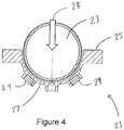
- the magnets 29 attract the magnetic ball 23 when the ball 23 coincides with magnetic field lines emanating from the magnets 29 into the recess 27. Therefore, the magnets 29 act upon the magnetic ball 23 to try to pull the magnetic ball into the recess 27 once the ball 23 is sufficiently far inside or close to the recess 27 that it is within the magnetic field of at least one of the magnets 29.
- the magnetic ball 23 and the magnets 29 may be arranged such that the magnets 29 repel the magnetic ball 23 when the ball 23 coincides with magnetic field lines emanating from the magnets 29.
- the magnets 29 may be mounted on the housing 25 at different locations from the ones illustrated in Figure 2 such that, when the magnetic ball 23 is sufficiently far inside or close to the recess 27, the magnets 29 act upon the magnetic ball 23 to try to push the magnetic ball 23 into the recess 27.
- the magnets 29 may be located at or near an opening or aperture of the recess 27 through which the magnetic ball 23 will enter the recess 27. Magnetic field lines emanating from the magnets 29 may point downwards into the recess from near the opening or aperture.
- strength and magnetic field lines of the magnets 29, the magnetic ball 23 may need to overcome a small resistance when being placed inside the recess 27.
- the magnets 29 may be positioned such that entry of the magnetic ball 23 into the recess 27 is guided by the magnetic field lines of the magnets 29.
- the magnetic field lines may for instance create a potential well in the recess 27, into which the magnetic ball 23 will inevitably fall when the magnets 29 act upon the ball 23 without further input from a user.
- the magnets 29 are permanent magnets. However, in other examples, the magnets 29 may be a different type of magnets, such as electromagnets. In some embodiments, there may be one or more permanent magnets 291 and one or more electromagnets 293, as illustrated in Figure 6 . Advantageously this may help ensure that the magnetic ball 23 is urged to remain within the recess 27 even when there is no power to the trackball 21.
- magnets 29 are illustrated in Figure 2 , a different number of magnets 29 may be present. For instance, some embodiments may include only one magnet 29, while other embodiments may include three or more magnets 29 (as illustrated in Figure 6 ).
- the position(s) of the magnet(s) may be chosen to try to ensure optimal attraction/repulsion of the magnetic ball 23, depending on the number of magnets and/or other factors. For instance, it may be advantageous for the magnet to be located in line with or at a central, lowest point of the recess 27 if there is only one magnet. If there are two or more magnets, it may be advantageous for them to be equally offset from the centre of the recess 27, as illustrated in Figure 2 and 4 , for example, or for one of them to be located in line with or at the centre of the recess 27 and for others to be equally offset from the centre of the recess 27, as illustrated in Figure 6 . Alternatively, it may be advantageous for the magnet(s) to be located at other positions, depending on the application and/or other parameters of the trackball 21, such as the shape and/or position of the recess 27.
- the magnet(s) may be positioned to achieve particular respective frictional effects on the ball 23.
- the magnet(s) may be positioned such that equal frictional forces are applied to the ball 23 at the bearing elements.
- it may be desired to create a greater frictional force at one or some of the bearing elements, in which case the magnets and bearing elements may be positioned accordingly, e.g. with two magnets closer to a bearing element at which it is desired to have more friction than to a bearing element at which it is desired to have less friction.
- three bearing elements and three magnets are provided in the trackball 21, the bearing elements and the magnets being positioned such that the same frictional force is applied at each bearing element, to create a uniform frictional effect on the ball 23.
- the bearing elements may for example be equidistantly spaced from each other, and the magnets may also be equidistantly spaced from each other. In other embodiments, the bearing element(s) and the magnet(s) may be arranged differently.
- the magnet(s) may be arranged to apply to the magnetic ball 23 a magnetic force that is greater in magnitude than the weight of the magnetic ball 23, such that the magnetic ball 23 is retained in the recess 27 even if the trackball 21 is inverted.
- the magnitude of the magnetic force may be arranged to be at least twice the weight of the magnetic ball 23. In such cases, a user must apply a force at least twice the weight of the magnetic ball 23 in order to remove the magnetic ball 23 from the recess 27.
- the magnets may be positioned such that they are closest to the lower hemisphere of the magnetic ball 23 when the ball 23 is in the recess 27.
- the magnets may for example be positioned below the "equator" line of the recess 27 and/or the magnetic ball 23.
- the material of the housing of the trackball 21 is magnetically permeable at least in the vicinity of the recess 27 to allow the magnetic field of the magnet(s) to permeate through the walls of the housing into the recess 27, where the magnetic field acts upon the magnetic ball 23 to urge the ball to remain in the recess 27.
- the trackball 21 also includes means for moving the magnets 29 relative to the recess 27 between a first position and a second position so that a distance between the magnets 29 and the magnetic ball 23 is varied. For instance, in the first position, the magnets 29 may be closer to the recess 27 (and therefore, when the magnetic ball 23 is in the recess 27, closer the magnetic ball 23) than they are when the magnets 29 are in the second position. Such movement is illustrated schematically in Figure 2 by two double-headed arrows.
- movement of the magnets 29 to be closer to or further away from the recess 27 (and therefore the magnetic ball 23) may allow a magnitude of attractive/repulsive force experienced by the magnetic ball 23 to be controlled and varied.
- the means for moving the magnets 29 may be or include a motor, a solenoid, a rack and pinion, a linear guide, a lever arrangement or a screw thread.
- the position of the magnets 29 may be adjustable during use of the trackball 21, e.g. through actuation of a button or other input means of the trackball 21.
- the area on the trackball 21 indicated with a "+" may be an input means arranged to cause the magnets 29 to move towards the magnetic ball 23 to increase the magnetic force experienced by the ball 23 as a result of the magnetic fields of the magnet 29. This may increase the friction between the ball 23 and the bearing element(s) supporting the ball 23 (e.g. the curved surface of the recess 27 or discrete bearing elements discussed above).
- a user of the trackball 21 may need to apply a greater tangential force (tracking force) to the magnetic ball 23 to cause the ball 23 to rotate in the recess 27 relative to the housing 25, which will be perceived as greater resistance to movement, by a user.
- a greater tangential force tilting force
- a user of the trackball 21 may therefore adjust the required force according to his or her preference, and/or to make the trackball 21 more suitable for use in specific applications. For instance, it may be advantageous to be able to increase or decrease the friction between the magnetic ball 23 and the bearing element(s) when very fine control of the ball 23 is required, such as when the trackball 21 is being used to control surgical or other medical equipment.
- a controller of the trackball 21 and/or other device in conjunction with which the trackball 21 is being used may be able to change the position of the magnets 29 to adjust the required force, e.g. in dependence on an output of the device in conjunction with which the trackball 21 is being used. This may enable the trackball 21 to provide feedback or other information to a user of the trackball 21.
- the trackball 21 may adjust the positions of the magnets 29, and therefore change the tracking force required to rotate the magnetic ball 23 relative to the housing 25, to indicate to a user that a cursor being controlled by the user with the ball 23 has reached an edge of a screen or other feature; that the user has scrolled past the end of a page or list; that a file or folder being dragged by the user from one disk location to another disk location is of a particular size (a larger file or folder may for example trigger an increase in the tangential force required to rotate the ball 23); and/or that the user has initiated or completed a particular operation.
- the controller may respond to commands received from different software or firmware applications, functions or tasks to provide application-specified feedback through increased or decreased friction for the magnetic ball 23.
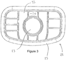
- the trackball 21 includes a capacitive user input device 35.
- a capacitive user input device 35 may be arranged to receive one or more types of user input.
- the capacitive user input device 35 may be divided into a plurality of different areas, each area having a respective type of user input.
- the area indicated with a "+” enables a user to move the magnets 29 towards the magnetic ball 23, to increase the magnetic force experienced by the ball 23 and therefore increase the force required to rotate the ball 23 in the recess 27 relative to the housing 25.
- the area indicated with a "-" enables the user to move the magnets 29 away from the magnetic ball 23, to decrease the magnetic force experienced by the ball 23 and therefore decrease the force required to rotate the ball 23 in the recess 27 relative to the housing 25.
- Other areas of the capacitive user input device 35 may be arranged to provide other functions, such as a zooming function, an application-switching function, a freeze function, a cancel function, a label function, a volume control function, functions corresponding to a left mouse click, a right mouse click, a scroll wheel or other user input functions, depending on the application of the trackball 21.
- functions such as a zooming function, an application-switching function, a freeze function, a cancel function, a label function, a volume control function, functions corresponding to a left mouse click, a right mouse click, a scroll wheel or other user input functions, depending on the application of the trackball 21.
- a capacitive user input device 35 divided into a plurality of areas corresponding to different functions may reduce or minimise the number of components that can come into contact with a user of the trackball 21.
- the single capacitive user input device 35 may for instance replace all of the buttons 15 illustrated in Figure 1 , such that there are fewer or no separate parts positioned adjacent to one another.
- the single capacitive user input device 35 may therefore significantly reduce the number of places (e.g. gaps between components) in which dirt, oil, water, bacteria, viruses, etc. can accumulate.
- a single capacitive user input device 35 may be easier to clean than mechanical buttons.
- the single capacitive user input device 35 may have a single surface, making it easy to wipe, spray, sluice or otherwise clean. The surface may be substantially flat and/or smooth.
- Movement of the ball may be sensed using the sealed ball arrangement described in our patent GB2387428 , which then allows easy cleaning of the arrangement.
- the electromagnet may be arranged such that the strength of the magnetic field emanating from the electromagnet can be varied, e.g. by applying a different voltage or load. This may be used as an additional or alternative means for varying the effect of the electromagnet on the magnetic ball 23, e.g. the magnitude of the force the magnetic ball 23 experiences due to the electromagnet.
- the embodiments described above and illustrated in the figures include a plurality of magnets, other embodiments may include only a single magnet.
- acceleration refers to both positive acceleration and negative acceleration (the latter may also be referred to as “deceleration”)
Landscapes
- Engineering & Computer Science (AREA)
- General Engineering & Computer Science (AREA)
- Theoretical Computer Science (AREA)
- Human Computer Interaction (AREA)
- Physics & Mathematics (AREA)
- General Physics & Mathematics (AREA)
- Position Input By Displaying (AREA)
Applications Claiming Priority (2)
| Application Number | Priority Date | Filing Date | Title |
|---|---|---|---|
| GB1609926.9A GB2551150B (en) | 2016-06-06 | 2016-06-06 | Trackballs |
| PCT/GB2017/051640 WO2017212252A1 (en) | 2016-06-06 | 2017-06-06 | Trackballs |
Publications (2)
| Publication Number | Publication Date |
|---|---|
| EP3465386A1 EP3465386A1 (en) | 2019-04-10 |
| EP3465386B1 true EP3465386B1 (en) | 2021-05-12 |
Family
ID=56508191
Family Applications (1)
| Application Number | Title | Priority Date | Filing Date |
|---|---|---|---|
| EP17730898.8A Active EP3465386B1 (en) | 2016-06-06 | 2017-06-06 | Trackballs |
Country Status (5)
| Country | Link |
|---|---|
| US (1) | US10775907B2 (enExample) |
| EP (1) | EP3465386B1 (enExample) |
| JP (1) | JP6914276B2 (enExample) |
| GB (1) | GB2551150B (enExample) |
| WO (1) | WO2017212252A1 (enExample) |
Cited By (1)
| Publication number | Priority date | Publication date | Assignee | Title |
|---|---|---|---|---|
| DE102023120396A1 (de) | 2023-08-01 | 2025-02-06 | Audi Aktiengesellschaft | Bedienvorrichtung für ein Kraftfahrzeug, Kraftfahrzeug mit einer Bedienvorrichtung und Verfahren zum Betreiben einer Bedienvorrichtung |
Families Citing this family (5)
| Publication number | Priority date | Publication date | Assignee | Title |
|---|---|---|---|---|
| CN109766019B (zh) * | 2019-02-14 | 2022-03-22 | 超越科技股份有限公司 | 一种轨迹球鼠标及其实现防淋雨和电磁兼容的方法 |
| EP3835885B1 (fr) * | 2019-12-10 | 2023-12-06 | The Swatch Group Research and Development Ltd | Montre pourvue d'un organe de commande |
| USD950552S1 (en) | 2020-05-06 | 2022-05-03 | ACCO Brands Corporation | Computer input device |
| US11531411B2 (en) | 2020-05-29 | 2022-12-20 | ACCO Brands Corporation | Computer input device |
| JP2024037172A (ja) * | 2022-09-06 | 2024-03-18 | ブラックマジック デザイン ピーティーワイ リミテッド | 入力デバイス |
Citations (1)
| Publication number | Priority date | Publication date | Assignee | Title |
|---|---|---|---|---|
| GB2387428A (en) * | 2002-04-12 | 2003-10-15 | Cursor Controls Ltd | Improved computer input device |
Family Cites Families (20)
| Publication number | Priority date | Publication date | Assignee | Title |
|---|---|---|---|---|
| JPS6275830A (ja) * | 1985-09-30 | 1987-04-07 | Fujitsu Ltd | 位置情報入力装置とその制御方法 |
| US5696537A (en) * | 1991-06-20 | 1997-12-09 | Tandberg Data Storage As | Mouse for data entry and control with control of ball friction force |
| US6084574A (en) * | 1992-10-05 | 2000-07-04 | Logitech, Inc. | Compact cursor pointing device utilizing photodetector array |
| US6172665B1 (en) * | 1994-11-14 | 2001-01-09 | Edward T. Bullister | Mouse and trackball with optimal measurement optics |
| US6144370A (en) * | 1996-05-08 | 2000-11-07 | The University Of North Carolina At Charlotte | Electromagnetic active trackball control system using magnets energized in sequence which cause the trackball to move |
| DE19700647C1 (de) * | 1997-01-10 | 1998-07-02 | Ericsson Telefon Ab L M | Dateneingabevorrichtung |
| GB2341439B (en) * | 1998-09-14 | 2003-02-12 | Penny & Giles Comp Products | Control device |
| AU5397499A (en) * | 1998-10-01 | 2000-04-26 | Gateway, Inc. | Capacitive switch for a pointing device |
| US6262818B1 (en) | 1998-10-07 | 2001-07-17 | Institute Of Applied Optics, Swiss Federal Institute Of Technology | Method for simultaneous amplitude and quantitative phase contrast imaging by numerical reconstruction of digital holograms |
| JP3855561B2 (ja) * | 1999-10-15 | 2006-12-13 | 富士ゼロックス株式会社 | 触覚力覚呈示装置及び情報入出力装置 |
| JP2002236553A (ja) * | 2001-02-09 | 2002-08-23 | Furuno Electric Co Ltd | トラックボールユニット |
| US7522155B2 (en) * | 2003-01-16 | 2009-04-21 | Panasonic Corporation | Trackball device and vehicle incorporating the same |
| JP2004265188A (ja) * | 2003-03-03 | 2004-09-24 | Matsushita Electric Ind Co Ltd | トラックボール装置 |
| DE10332614B4 (de) * | 2003-07-17 | 2005-06-30 | Siemens Ag | Eingabegerät für eine Datenverarbeitungsanlage |
| JP2006189950A (ja) * | 2004-12-28 | 2006-07-20 | Tokai Rika Co Ltd | 入力装置及び転動体の制動構造 |
| JP2006215788A (ja) * | 2005-02-03 | 2006-08-17 | Tamagawa Seiki Co Ltd | トラックボール装置 |
| US8866743B2 (en) * | 2007-07-16 | 2014-10-21 | Blackberry Limited | Navigational tool with drag-based tactile feedback on a handheld wireless communication device |
| GB2462434B (en) * | 2008-08-05 | 2013-02-06 | Cursor Controls Ltd | Pointing Device |
| JP2011145724A (ja) * | 2010-01-12 | 2011-07-28 | Alps Electric Co Ltd | 入力装置 |
| JP2012221012A (ja) * | 2011-04-05 | 2012-11-12 | Panasonic Corp | 入力装置 |
-
2016
- 2016-06-06 GB GB1609926.9A patent/GB2551150B/en active Active
-
2017
- 2017-06-06 WO PCT/GB2017/051640 patent/WO2017212252A1/en not_active Ceased
- 2017-06-06 US US16/306,742 patent/US10775907B2/en active Active
- 2017-06-06 EP EP17730898.8A patent/EP3465386B1/en active Active
- 2017-06-06 JP JP2018563154A patent/JP6914276B2/ja active Active
Patent Citations (1)
| Publication number | Priority date | Publication date | Assignee | Title |
|---|---|---|---|---|
| GB2387428A (en) * | 2002-04-12 | 2003-10-15 | Cursor Controls Ltd | Improved computer input device |
Cited By (1)
| Publication number | Priority date | Publication date | Assignee | Title |
|---|---|---|---|---|
| DE102023120396A1 (de) | 2023-08-01 | 2025-02-06 | Audi Aktiengesellschaft | Bedienvorrichtung für ein Kraftfahrzeug, Kraftfahrzeug mit einer Bedienvorrichtung und Verfahren zum Betreiben einer Bedienvorrichtung |
Also Published As
| Publication number | Publication date |
|---|---|
| US10775907B2 (en) | 2020-09-15 |
| JP2019517697A (ja) | 2019-06-24 |
| GB2551150B (en) | 2020-07-01 |
| GB2551150A (en) | 2017-12-13 |
| US20190138121A1 (en) | 2019-05-09 |
| JP6914276B2 (ja) | 2021-08-04 |
| EP3465386A1 (en) | 2019-04-10 |
| GB201609926D0 (en) | 2016-07-20 |
| WO2017212252A1 (en) | 2017-12-14 |
Similar Documents
| Publication | Publication Date | Title |
|---|---|---|
| EP3465386B1 (en) | Trackballs | |
| CN110770680A (zh) | 用于机动车辆的触感操作装置 | |
| US9170658B2 (en) | Self-centering tactile thumb joystick for use on a touch screen | |
| US7939774B2 (en) | Tunable keys for a control device | |
| US6654003B2 (en) | Cursor control device | |
| CN101512474B (zh) | 触摸板或触摸屏以及用于触摸板或触摸屏的调节元件 | |
| US8040331B2 (en) | Dual-mode rotatable input device | |
| JP5829432B2 (ja) | 磁気マウスデバイスおよびマウスパッドシステム | |
| CN110716638A (zh) | 电容性机动车操作系统 | |
| US6354945B1 (en) | Controller | |
| TWI457792B (zh) | 顯示功能鍵盤、數字鍵盤或其它使用者輸入裝置之透光鍵組件 | |
| US20210309106A1 (en) | Motor Vehicle | |
| WO2008012177A1 (de) | Bedienvorrichtung für ein kochfeld | |
| JP2017168104A (ja) | 静電付着に基づく触覚出力デバイス | |
| EP2555086A3 (en) | Sleeve and control device with such sleeve | |
| JP2019517697A5 (enExample) | ||
| JP2022155566A (ja) | 静電容量式タッチスクリーンのための回転コントロール入力装置 | |
| KR102011022B1 (ko) | 마그네틱 터치 펜 | |
| KR101616248B1 (ko) | 필기감을 조절하는 스타일러스 펜 | |
| JP2007257281A (ja) | 操作ダイヤルにおけるクリック機構 | |
| DE10304985B3 (de) | Schaltgerät | |
| JP6969257B2 (ja) | リモコン装置 | |
| JP2000056919A (ja) | コントローラ | |
| US10013898B2 (en) | Multi-position biased rotating logo component | |
| CN222014728U (zh) | 鼠标 |
Legal Events
| Date | Code | Title | Description |
|---|---|---|---|
| STAA | Information on the status of an ep patent application or granted ep patent |
Free format text: STATUS: UNKNOWN |
|
| STAA | Information on the status of an ep patent application or granted ep patent |
Free format text: STATUS: THE INTERNATIONAL PUBLICATION HAS BEEN MADE |
|
| PUAI | Public reference made under article 153(3) epc to a published international application that has entered the european phase |
Free format text: ORIGINAL CODE: 0009012 |
|
| STAA | Information on the status of an ep patent application or granted ep patent |
Free format text: STATUS: REQUEST FOR EXAMINATION WAS MADE |
|
| 17P | Request for examination filed |
Effective date: 20181204 |
|
| AK | Designated contracting states |
Kind code of ref document: A1 Designated state(s): AL AT BE BG CH CY CZ DE DK EE ES FI FR GB GR HR HU IE IS IT LI LT LU LV MC MK MT NL NO PL PT RO RS SE SI SK SM TR |
|
| AX | Request for extension of the european patent |
Extension state: BA ME |
|
| DAV | Request for validation of the european patent (deleted) | ||
| DAX | Request for extension of the european patent (deleted) | ||
| STAA | Information on the status of an ep patent application or granted ep patent |
Free format text: STATUS: EXAMINATION IS IN PROGRESS |
|
| 17Q | First examination report despatched |
Effective date: 20200116 |
|
| GRAP | Despatch of communication of intention to grant a patent |
Free format text: ORIGINAL CODE: EPIDOSNIGR1 |
|
| STAA | Information on the status of an ep patent application or granted ep patent |
Free format text: STATUS: GRANT OF PATENT IS INTENDED |
|
| INTG | Intention to grant announced |
Effective date: 20201214 |
|
| GRAS | Grant fee paid |
Free format text: ORIGINAL CODE: EPIDOSNIGR3 |
|
| GRAA | (expected) grant |
Free format text: ORIGINAL CODE: 0009210 |
|
| STAA | Information on the status of an ep patent application or granted ep patent |
Free format text: STATUS: THE PATENT HAS BEEN GRANTED |
|
| AK | Designated contracting states |
Kind code of ref document: B1 Designated state(s): AL AT BE BG CH CY CZ DE DK EE ES FI FR GB GR HR HU IE IS IT LI LT LU LV MC MK MT NL NO PL PT RO RS SE SI SK SM TR |
|
| REG | Reference to a national code |
Ref country code: GB Ref legal event code: FG4D |
|
| REG | Reference to a national code |
Ref country code: CH Ref legal event code: EP |
|
| REG | Reference to a national code |
Ref country code: DE Ref legal event code: R096 Ref document number: 602017038513 Country of ref document: DE |
|
| REG | Reference to a national code |
Ref country code: NL Ref legal event code: FP Ref country code: IE Ref legal event code: FG4D |
|
| REG | Reference to a national code |
Ref country code: AT Ref legal event code: REF Ref document number: 1392609 Country of ref document: AT Kind code of ref document: T Effective date: 20210615 |
|
| REG | Reference to a national code |
Ref country code: NO Ref legal event code: T2 Effective date: 20210512 |
|
| REG | Reference to a national code |
Ref country code: LT Ref legal event code: MG9D |
|
| REG | Reference to a national code |
Ref country code: AT Ref legal event code: MK05 Ref document number: 1392609 Country of ref document: AT Kind code of ref document: T Effective date: 20210512 |
|
| PG25 | Lapsed in a contracting state [announced via postgrant information from national office to epo] |
Ref country code: HR Free format text: LAPSE BECAUSE OF FAILURE TO SUBMIT A TRANSLATION OF THE DESCRIPTION OR TO PAY THE FEE WITHIN THE PRESCRIBED TIME-LIMIT Effective date: 20210512 Ref country code: AT Free format text: LAPSE BECAUSE OF FAILURE TO SUBMIT A TRANSLATION OF THE DESCRIPTION OR TO PAY THE FEE WITHIN THE PRESCRIBED TIME-LIMIT Effective date: 20210512 Ref country code: BG Free format text: LAPSE BECAUSE OF FAILURE TO SUBMIT A TRANSLATION OF THE DESCRIPTION OR TO PAY THE FEE WITHIN THE PRESCRIBED TIME-LIMIT Effective date: 20210812 Ref country code: LT Free format text: LAPSE BECAUSE OF FAILURE TO SUBMIT A TRANSLATION OF THE DESCRIPTION OR TO PAY THE FEE WITHIN THE PRESCRIBED TIME-LIMIT Effective date: 20210512 Ref country code: FI Free format text: LAPSE BECAUSE OF FAILURE TO SUBMIT A TRANSLATION OF THE DESCRIPTION OR TO PAY THE FEE WITHIN THE PRESCRIBED TIME-LIMIT Effective date: 20210512 |
|
| PG25 | Lapsed in a contracting state [announced via postgrant information from national office to epo] |
Ref country code: PT Free format text: LAPSE BECAUSE OF FAILURE TO SUBMIT A TRANSLATION OF THE DESCRIPTION OR TO PAY THE FEE WITHIN THE PRESCRIBED TIME-LIMIT Effective date: 20210913 Ref country code: PL Free format text: LAPSE BECAUSE OF FAILURE TO SUBMIT A TRANSLATION OF THE DESCRIPTION OR TO PAY THE FEE WITHIN THE PRESCRIBED TIME-LIMIT Effective date: 20210512 Ref country code: RS Free format text: LAPSE BECAUSE OF FAILURE TO SUBMIT A TRANSLATION OF THE DESCRIPTION OR TO PAY THE FEE WITHIN THE PRESCRIBED TIME-LIMIT Effective date: 20210512 Ref country code: SE Free format text: LAPSE BECAUSE OF FAILURE TO SUBMIT A TRANSLATION OF THE DESCRIPTION OR TO PAY THE FEE WITHIN THE PRESCRIBED TIME-LIMIT Effective date: 20210512 Ref country code: IS Free format text: LAPSE BECAUSE OF FAILURE TO SUBMIT A TRANSLATION OF THE DESCRIPTION OR TO PAY THE FEE WITHIN THE PRESCRIBED TIME-LIMIT Effective date: 20210912 Ref country code: LV Free format text: LAPSE BECAUSE OF FAILURE TO SUBMIT A TRANSLATION OF THE DESCRIPTION OR TO PAY THE FEE WITHIN THE PRESCRIBED TIME-LIMIT Effective date: 20210512 Ref country code: GR Free format text: LAPSE BECAUSE OF FAILURE TO SUBMIT A TRANSLATION OF THE DESCRIPTION OR TO PAY THE FEE WITHIN THE PRESCRIBED TIME-LIMIT Effective date: 20210813 |
|
| PG25 | Lapsed in a contracting state [announced via postgrant information from national office to epo] |
Ref country code: SM Free format text: LAPSE BECAUSE OF FAILURE TO SUBMIT A TRANSLATION OF THE DESCRIPTION OR TO PAY THE FEE WITHIN THE PRESCRIBED TIME-LIMIT Effective date: 20210512 Ref country code: SK Free format text: LAPSE BECAUSE OF FAILURE TO SUBMIT A TRANSLATION OF THE DESCRIPTION OR TO PAY THE FEE WITHIN THE PRESCRIBED TIME-LIMIT Effective date: 20210512 Ref country code: ES Free format text: LAPSE BECAUSE OF FAILURE TO SUBMIT A TRANSLATION OF THE DESCRIPTION OR TO PAY THE FEE WITHIN THE PRESCRIBED TIME-LIMIT Effective date: 20210512 Ref country code: RO Free format text: LAPSE BECAUSE OF FAILURE TO SUBMIT A TRANSLATION OF THE DESCRIPTION OR TO PAY THE FEE WITHIN THE PRESCRIBED TIME-LIMIT Effective date: 20210512 Ref country code: DK Free format text: LAPSE BECAUSE OF FAILURE TO SUBMIT A TRANSLATION OF THE DESCRIPTION OR TO PAY THE FEE WITHIN THE PRESCRIBED TIME-LIMIT Effective date: 20210512 Ref country code: CZ Free format text: LAPSE BECAUSE OF FAILURE TO SUBMIT A TRANSLATION OF THE DESCRIPTION OR TO PAY THE FEE WITHIN THE PRESCRIBED TIME-LIMIT Effective date: 20210512 Ref country code: EE Free format text: LAPSE BECAUSE OF FAILURE TO SUBMIT A TRANSLATION OF THE DESCRIPTION OR TO PAY THE FEE WITHIN THE PRESCRIBED TIME-LIMIT Effective date: 20210512 |
|
| REG | Reference to a national code |
Ref country code: CH Ref legal event code: PL |
|
| REG | Reference to a national code |
Ref country code: DE Ref legal event code: R097 Ref document number: 602017038513 Country of ref document: DE |
|
| PLBE | No opposition filed within time limit |
Free format text: ORIGINAL CODE: 0009261 |
|
| STAA | Information on the status of an ep patent application or granted ep patent |
Free format text: STATUS: NO OPPOSITION FILED WITHIN TIME LIMIT |
|
| PG25 | Lapsed in a contracting state [announced via postgrant information from national office to epo] |
Ref country code: MC Free format text: LAPSE BECAUSE OF FAILURE TO SUBMIT A TRANSLATION OF THE DESCRIPTION OR TO PAY THE FEE WITHIN THE PRESCRIBED TIME-LIMIT Effective date: 20210512 Ref country code: LU Free format text: LAPSE BECAUSE OF NON-PAYMENT OF DUE FEES Effective date: 20210606 |
|
| 26N | No opposition filed |
Effective date: 20220215 |
|
| PG25 | Lapsed in a contracting state [announced via postgrant information from national office to epo] |
Ref country code: LI Free format text: LAPSE BECAUSE OF NON-PAYMENT OF DUE FEES Effective date: 20210630 Ref country code: IE Free format text: LAPSE BECAUSE OF NON-PAYMENT OF DUE FEES Effective date: 20210606 Ref country code: CH Free format text: LAPSE BECAUSE OF NON-PAYMENT OF DUE FEES Effective date: 20210630 |
|
| PG25 | Lapsed in a contracting state [announced via postgrant information from national office to epo] |
Ref country code: IS Free format text: LAPSE BECAUSE OF FAILURE TO SUBMIT A TRANSLATION OF THE DESCRIPTION OR TO PAY THE FEE WITHIN THE PRESCRIBED TIME-LIMIT Effective date: 20210912 Ref country code: AL Free format text: LAPSE BECAUSE OF FAILURE TO SUBMIT A TRANSLATION OF THE DESCRIPTION OR TO PAY THE FEE WITHIN THE PRESCRIBED TIME-LIMIT Effective date: 20210512 |
|
| P01 | Opt-out of the competence of the unified patent court (upc) registered |
Effective date: 20230515 |
|
| PG25 | Lapsed in a contracting state [announced via postgrant information from national office to epo] |
Ref country code: CY Free format text: LAPSE BECAUSE OF FAILURE TO SUBMIT A TRANSLATION OF THE DESCRIPTION OR TO PAY THE FEE WITHIN THE PRESCRIBED TIME-LIMIT Effective date: 20210512 |
|
| PG25 | Lapsed in a contracting state [announced via postgrant information from national office to epo] |
Ref country code: HU Free format text: LAPSE BECAUSE OF FAILURE TO SUBMIT A TRANSLATION OF THE DESCRIPTION OR TO PAY THE FEE WITHIN THE PRESCRIBED TIME-LIMIT; INVALID AB INITIO Effective date: 20170606 |
|
| PG25 | Lapsed in a contracting state [announced via postgrant information from national office to epo] |
Ref country code: MK Free format text: LAPSE BECAUSE OF FAILURE TO SUBMIT A TRANSLATION OF THE DESCRIPTION OR TO PAY THE FEE WITHIN THE PRESCRIBED TIME-LIMIT Effective date: 20210512 |
|
| PG25 | Lapsed in a contracting state [announced via postgrant information from national office to epo] |
Ref country code: TR Free format text: LAPSE BECAUSE OF FAILURE TO SUBMIT A TRANSLATION OF THE DESCRIPTION OR TO PAY THE FEE WITHIN THE PRESCRIBED TIME-LIMIT Effective date: 20210512 |
|
| PG25 | Lapsed in a contracting state [announced via postgrant information from national office to epo] |
Ref country code: MT Free format text: LAPSE BECAUSE OF FAILURE TO SUBMIT A TRANSLATION OF THE DESCRIPTION OR TO PAY THE FEE WITHIN THE PRESCRIBED TIME-LIMIT Effective date: 20210512 |
|
| PGFP | Annual fee paid to national office [announced via postgrant information from national office to epo] |
Ref country code: DE Payment date: 20250603 Year of fee payment: 9 |
|
| PGFP | Annual fee paid to national office [announced via postgrant information from national office to epo] |
Ref country code: GB Payment date: 20250520 Year of fee payment: 9 |
|
| PGFP | Annual fee paid to national office [announced via postgrant information from national office to epo] |
Ref country code: NO Payment date: 20250613 Year of fee payment: 9 |
|
| PGFP | Annual fee paid to national office [announced via postgrant information from national office to epo] |
Ref country code: NL Payment date: 20250620 Year of fee payment: 9 Ref country code: BE Payment date: 20250609 Year of fee payment: 9 |
|
| PGFP | Annual fee paid to national office [announced via postgrant information from national office to epo] |
Ref country code: FR Payment date: 20250606 Year of fee payment: 9 |
|
| PGFP | Annual fee paid to national office [announced via postgrant information from national office to epo] |
Ref country code: IT Payment date: 20250617 Year of fee payment: 9 |