EP3465057B1 - Heat exchanger tube - Google Patents
Heat exchanger tube Download PDFInfo
- Publication number
- EP3465057B1 EP3465057B1 EP17727102.0A EP17727102A EP3465057B1 EP 3465057 B1 EP3465057 B1 EP 3465057B1 EP 17727102 A EP17727102 A EP 17727102A EP 3465057 B1 EP3465057 B1 EP 3465057B1
- Authority
- EP
- European Patent Office
- Prior art keywords
- projections
- rib
- pipe
- ribs
- projection
- Prior art date
- Legal status (The legal status is an assumption and is not a legal conclusion. Google has not performed a legal analysis and makes no representation as to the accuracy of the status listed.)
- Active
Links
- 238000001704 evaporation Methods 0.000 description 13
- 230000008020 evaporation Effects 0.000 description 9
- 239000012530 fluid Substances 0.000 description 8
- 238000000034 method Methods 0.000 description 7
- 239000007788 liquid Substances 0.000 description 6
- 230000006911 nucleation Effects 0.000 description 6
- 238000010899 nucleation Methods 0.000 description 6
- 230000015572 biosynthetic process Effects 0.000 description 5
- 238000007373 indentation Methods 0.000 description 5
- 238000004519 manufacturing process Methods 0.000 description 5
- 239000000126 substance Substances 0.000 description 5
- 238000009835 boiling Methods 0.000 description 3
- 238000005516 engineering process Methods 0.000 description 3
- 239000003507 refrigerant Substances 0.000 description 3
- 230000002441 reversible effect Effects 0.000 description 3
- 238000009833 condensation Methods 0.000 description 2
- 230000005494 condensation Effects 0.000 description 2
- 230000007423 decrease Effects 0.000 description 2
- 239000000203 mixture Substances 0.000 description 2
- 238000005057 refrigeration Methods 0.000 description 2
- XLYOFNOQVPJJNP-UHFFFAOYSA-N water Substances O XLYOFNOQVPJJNP-UHFFFAOYSA-N 0.000 description 2
- 238000004378 air conditioning Methods 0.000 description 1
- 238000005452 bending Methods 0.000 description 1
- 239000012267 brine Substances 0.000 description 1
- 238000003889 chemical engineering Methods 0.000 description 1
- 230000001419 dependent effect Effects 0.000 description 1
- 238000011161 development Methods 0.000 description 1
- 230000018109 developmental process Effects 0.000 description 1
- 238000004821 distillation Methods 0.000 description 1
- 239000000463 material Substances 0.000 description 1
- 239000002184 metal Substances 0.000 description 1
- 239000011148 porous material Substances 0.000 description 1
- HPALAKNZSZLMCH-UHFFFAOYSA-M sodium;chloride;hydrate Chemical compound O.[Na+].[Cl-] HPALAKNZSZLMCH-UHFFFAOYSA-M 0.000 description 1
- 239000000243 solution Substances 0.000 description 1
- 231100000331 toxic Toxicity 0.000 description 1
- 230000002588 toxic effect Effects 0.000 description 1
- 230000007704 transition Effects 0.000 description 1
Images


Classifications
-
- F—MECHANICAL ENGINEERING; LIGHTING; HEATING; WEAPONS; BLASTING
- F28—HEAT EXCHANGE IN GENERAL
- F28F—DETAILS OF HEAT-EXCHANGE AND HEAT-TRANSFER APPARATUS, OF GENERAL APPLICATION
- F28F1/00—Tubular elements; Assemblies of tubular elements
- F28F1/10—Tubular elements and assemblies thereof with means for increasing heat-transfer area, e.g. with fins, with projections, with recesses
- F28F1/12—Tubular elements and assemblies thereof with means for increasing heat-transfer area, e.g. with fins, with projections, with recesses the means being only outside the tubular element
- F28F1/14—Tubular elements and assemblies thereof with means for increasing heat-transfer area, e.g. with fins, with projections, with recesses the means being only outside the tubular element and extending longitudinally
- F28F1/16—Tubular elements and assemblies thereof with means for increasing heat-transfer area, e.g. with fins, with projections, with recesses the means being only outside the tubular element and extending longitudinally the means being integral with the element, e.g. formed by extrusion
- F28F1/18—Tubular elements and assemblies thereof with means for increasing heat-transfer area, e.g. with fins, with projections, with recesses the means being only outside the tubular element and extending longitudinally the means being integral with the element, e.g. formed by extrusion the element being built-up from finned sections
-
- F—MECHANICAL ENGINEERING; LIGHTING; HEATING; WEAPONS; BLASTING
- F28—HEAT EXCHANGE IN GENERAL
- F28F—DETAILS OF HEAT-EXCHANGE AND HEAT-TRANSFER APPARATUS, OF GENERAL APPLICATION
- F28F1/00—Tubular elements; Assemblies of tubular elements
- F28F1/10—Tubular elements and assemblies thereof with means for increasing heat-transfer area, e.g. with fins, with projections, with recesses
- F28F1/12—Tubular elements and assemblies thereof with means for increasing heat-transfer area, e.g. with fins, with projections, with recesses the means being only outside the tubular element
- F28F1/34—Tubular elements and assemblies thereof with means for increasing heat-transfer area, e.g. with fins, with projections, with recesses the means being only outside the tubular element and extending obliquely
- F28F1/36—Tubular elements and assemblies thereof with means for increasing heat-transfer area, e.g. with fins, with projections, with recesses the means being only outside the tubular element and extending obliquely the means being helically wound fins or wire spirals
-
- F—MECHANICAL ENGINEERING; LIGHTING; HEATING; WEAPONS; BLASTING
- F28—HEAT EXCHANGE IN GENERAL
- F28F—DETAILS OF HEAT-EXCHANGE AND HEAT-TRANSFER APPARATUS, OF GENERAL APPLICATION
- F28F1/00—Tubular elements; Assemblies of tubular elements
- F28F1/10—Tubular elements and assemblies thereof with means for increasing heat-transfer area, e.g. with fins, with projections, with recesses
- F28F1/40—Tubular elements and assemblies thereof with means for increasing heat-transfer area, e.g. with fins, with projections, with recesses the means being only inside the tubular element
-
- F—MECHANICAL ENGINEERING; LIGHTING; HEATING; WEAPONS; BLASTING
- F28—HEAT EXCHANGE IN GENERAL
- F28F—DETAILS OF HEAT-EXCHANGE AND HEAT-TRANSFER APPARATUS, OF GENERAL APPLICATION
- F28F1/00—Tubular elements; Assemblies of tubular elements
- F28F1/10—Tubular elements and assemblies thereof with means for increasing heat-transfer area, e.g. with fins, with projections, with recesses
- F28F1/42—Tubular elements and assemblies thereof with means for increasing heat-transfer area, e.g. with fins, with projections, with recesses the means being both outside and inside the tubular element
- F28F1/422—Tubular elements and assemblies thereof with means for increasing heat-transfer area, e.g. with fins, with projections, with recesses the means being both outside and inside the tubular element with outside means integral with the tubular element and inside means integral with the tubular element
Definitions
- the invention relates to a heat exchanger tube according to the preamble of claim 1.
- Such metallic heat exchanger tubes are used in particular for evaporating liquids from pure substances or mixtures on the outside of the tube.
- Tube bundle heat exchangers are often used in which liquids of pure substances or mixtures evaporate on the outside of the tube and brine or water cools down on the inside of the tube.
- Such apparatuses are referred to as flooded evaporators.
- the size of the evaporator can be greatly reduced by intensifying the heat transfer on the outside and inside of the tube. This reduces the manufacturing costs of such devices.
- the amount of refrigerant required is reduced, which can make up a non-negligible proportion of the total system costs with the chlorine-free safety refrigerants that are predominantly used today.
- the risk potential can also be reduced by reducing the filling quantity.
- Today's high-performance pipes are already about four times more efficient than smooth pipes of the same diameter.
- integrally rolled finned tubes understood ribbed tubes in which the ribs were formed from the wall material of a smooth tube.
- ribbed tubes in which the ribs were formed from the wall material of a smooth tube.
- Various methods are known in this regard, with which the channels located between adjacent ribs are closed in such a way that connections between the channel and the environment remain in the form of pores or slits.
- essentially closed channels are formed by bending or folding over the ribs ( U.S. 3,696,861 ; U.S. 5,054,548 ; U.S. 7,178,361 B2 ), by splitting and upsetting the ribs ( DE 2 758 526 C2 ; U.S. 4,577,381 ) and by notching and upsetting the ribs ( U.S. 4,660,630 ; EP 0 713 072 B1 ; U.S. 4,216,826 ) generated.
- the highest performance commercially available finned tubes for flooded evaporators have a fin structure on the tube face with a fin density of 55 to 60 fins per inch ( U.S. 5,669,441 ; U.S. 5,697,430 ; DE 197 57 526 C1 ). This corresponds to a rib spacing of approx. 0.45 to 0.40 mm.
- a smaller rib pitch inevitably requires equally finer tools.
- finer tools are subject to a higher risk of breakage and faster wear.
- the tools currently available enable the reliable production of finned tubes with fin densities of a maximum of 60 fins per inch. Furthermore, as the fin pitch decreases, the production speed of the tubes becomes slower and consequently the manufacturing cost becomes higher.
- performance-enhanced evaporation structures can be produced on the outside of the tube with the same fin density by introducing additional structural elements in the area of the groove base between the fins. Since the temperature of the rib is higher in the area of the bottom of the groove than in the area of the tip of the rib, structural elements for intensifying the formation of bubbles are particularly effective in this area. Examples of this are in EP 0 222 100 B1 ; U.S. 5,186,252 ; JP04039596A and U.S. 2007/0151715 A1 to find. What these inventions have in common is that the structural elements at the bottom of the groove do not have an undercut shape, which is why they do not sufficiently intensify the formation of bubbles.
- EP 1 223 400 B1 and EP 2 101 136 B1 it is proposed to produce undercut secondary grooves at the bottom of the groove between the ribs, which extend continuously along the primary groove.
- the cross section of these secondary grooves can remain constant or be varied at regular intervals.
- the pamphlets U.S. 2006/0213346 A1 and U.S. 2005/0145377 A1 disclose improved heat transfer surfaces that facilitate heat transfer from one side of the surface to the other. Described herein is another method of improving heat transfer surfaces by using a tool to cut the inner surface of a tube.
- the tool has at least one tip with a cutting edge and a lifting edge.
- Protrusions are formed by cutting the inner surface of a heat exchanger tube and raising the cut surface.
- Boiling surfaces produced in this way have a multiplicity of primary grooves, projections and secondary grooves, for example to form boiling cavities.
- the invention is based on the object of specifying a performance-enhanced heat exchanger tube for evaporating liquids.
- the structured area can in principle also be formed on the outside of the tube.
- the structures described can be used for both evaporator and condenser tubes.
- the structures are also suitable for single-phase fluid flows, such as water.
- a cavity in adjacent projections is present when the respective shortest distance between adjacent projections decreases, starting from the tube wall to the point of the projections that is furthest away from the tube wall.
- the adjacent projections forming a cavity incline toward one another.
- the cavity is formed with the opposing concave surfaces of adjacent projections.
- the surfaces of the adjacent projections forming a cavity extend over it in the manner of a vault.
- Protrusion height is conveniently defined as the dimension of a protrusion in the radial direction. The height of the projection is then, in the radial direction, the distance starting from the pipe wall to the point of the projection which is furthest away from the pipe wall.
- the notch depth of the notches is the distance measured in the radial direction from the original rib tip to the deepest point of the notch. In other words: the notch depth is the difference between the original rib height and the remaining rib height at the deepest point of a notch.
- the invention is based on the consideration that the cavities formed between the tube wall and the folded-over projections or between adjacent projections form the cavities according to the invention.
- the projections are cut and set up or folded over in such a way that they form such cavities.
- the projections touch the tube wall or form cavities without direct contact.
- the production can take place directly via adapted cutting geometries or via a secondary forming process, whereby the secondary tool used can be smooth or have an additional structure.
- the tubes can be arranged horizontally or vertically during evaporation, for example on the inside of the tube.
- the pipes are slightly inclined from the horizontal or the vertical.
- evaporators with horizontal tubes are usually used.
- vertical circulation evaporators are often used in chemical engineering to heat distillation columns. The evaporation of the substance takes place on the inside of vertical tubes.
- the temperature of the heat-emitting medium In order to enable heat transport between the heat-emitting medium and the evaporating substance, the temperature of the heat-emitting medium must be higher than the saturation temperature of the substance. This temperature difference is called the driving temperature difference. The higher the driving temperature difference, the more heat can be transferred. On the other hand, the aim is usually to keep the driving temperature difference small, as this is advantageous for process efficiency.
- the cavities according to the invention intensify the process of nucleate boiling in order to increase the heat transfer coefficient during evaporation.
- the formation of bubbles begins at nucleation sites. These nucleation sites are mostly small gas or vapor inclusions. When the growing bubble reaches a certain size, it detaches from the surface. If the nucleation site is flooded with liquid in the course of the bubble detachment, then the nucleation site is deactivated.
- the surface must therefore be designed as a cavity in such a way that when the bubble detaches, a small bubble remains, which then serves as the nucleus for a new cycle of bubble formation. This is achieved by arranging cavities on the surface in which a small bubble can remain after the bubble has detached.
- the tips of at least two projections touch or cross one another along the course of the ribs. This is particularly advantageous in reversible operation during the phase change, since the projections for the liquefaction protrude far out of the condensate and form a kind of cavity for the evaporation.
- the tips of at least two projections can touch or cross one another across the primary groove. This is advantageous in reversible operation during the phase change, since the projections for the liquefaction in turn protrude far out of the condensate and form a kind of cavity for the evaporation.
- the distance between the tip of the projection and the tube wall is also possible for the distance between the tip of the projection and the tube wall to be less than the remaining height of the ribs. This gives the projection a hook-like or loop-like shape directly above the pipe wall. Such rounded shapes are particularly advantageous for bubble nucleation in evaporation processes.
- At least one of the projections can be deformed in such a way that its tip touches the inside of the pipe.
- a bubble nucleus is formed by a hook-like or eyelet-like shape of the projection during the phase transition of a fluid heat transfer medium close to the tube wall. A particularly intensive heat exchange into the fluid takes place there via the tube wall.
- the indentations can be formed by cutting the inner ribs with a cutting depth transverse to the rib path to form rib layers and by raising the rib layers with a main orientation along the rib path between primary grooves.
- the process-side structuring of the heat exchanger tube according to the invention can be produced using a tool which in the DE 603 17 506 T2 is already described.
- the disclosure of this reference DE 603 17 506 T2 is fully included in the available documents.
- the projection height and the distance can be made variable and individually adapted to the requirements, for example the viscosity of the liquid or the flow rate.
- the tool used has a cutting edge for cutting through the fins on the inner surface of the tube to create layers of fins and a lifting edge for lifting the layers of fins to form the projections.
- the protrusions are formed without removing metal from the inner surface of the tube.
- the projections on the inner surface of the tube can be in the same or different processing than the
- the projections can vary in projection height, shape and alignment.
- the individual projections can be specifically adapted to one another and varied in relation to one another, so that, particularly in the case of laminar flow, the different rib heights dip into the different boundary layers of the flow in order to dissipate the heat to the tube wall.
- the height of the protrusion and the distance can also be individually adapted to the requirements, for example the viscosity of the fluid or the flow rate.
- a projection can have a pointed tip on the side facing away from the tube wall. This leads to optimized projection tip condensation in condenser tubes using two-phase fluids.
- a projection can have a curved tip on the side facing away from the pipe wall, the local radius of curvature of which is reduced as the distance from the pipe wall increases along the course of the projection.
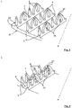
- the heat exchanger tube 1 shows schematically an oblique view of a pipe section of the Heat exchanger tube 1 with a structure according to the invention on the tube inside 22.
- the heat exchanger tube 1 has a tube wall 2, a tube outside 21 and a tube inside 22.
- continuously running, helically circumferential ribs 3 are formed from the tube wall 2.
- the longitudinal axis A of the tube runs at a certain angle relative to the ribs 3 .
- Continuously extending primary grooves 4 are formed between each adjacent ribs 3 .
- a plurality of projections 6 are deformed in pairs to one another to such an extent that cavities 10 are formed between adjacent projections 6 .
- the tips 61 of at least two projections 6 touch one another along the course of the ribs.
- the projections 6 are formed by cutting the ribs 3 with a cutting depth across the rib path to form layers of ribs and raising the layers of ribs with a main orientation along the rib path between primary grooves 4 .
- the indentations 7 between the projections 6 can also be formed in a rib 3 with an alternating indentation depth.
- FIG. 2 1 schematically shows an oblique view of a tube section of the heat exchanger tube 1 with a structure not according to the invention.
- a plurality of projections 6 are deformed in pairs to one another to such an extent that cavities 10 are formed between adjacent projections 6 .
- the tips 61 of at least two projections 6 extend beyond the primary groove 4 and touch one another.
- the tips 61 of projections 6 deformed in pairs relative to one another can also still have a certain distance from one another. However, this is so small that effective cavities 10 are nevertheless formed.
- the projections 6 are in turn made by cutting the ribs 3 with a cutting depth transverse to the rib course to form rib layers and by raising the rib layers with a main orientation along the Rib course between primary grooves 4 formed.
- the indentations 7 between the projections 6 can also be formed in a rib 3 with an alternating indentation depth.
- 3 1 schematically shows an oblique view of a tube section of the heat exchanger tube 1 with a further structure not according to the invention on the inside 22 of the tube.
- the distance between the tips 61 of a projection and the tube wall is less than the residual rib height.
- a hook-like shape is created.
- a projection 6 can be deformed in such a way that its tip 61 touches the inside 22 of the tube. In this in figure 3 not shown case preferably creates a loop-like shape.
- the projections 6 are in turn by cutting the ribs 3 analogous to the Figures 1 and 2 educated.
- 4 1 schematically shows a rib section 31 with different notch depths t 1 , t 2 , t 3 .
- the terms cutting depth and notch depth represent the same terminology. Dashed is indicated in the 4 the original formed helical circumferential rib 3. From this the protrusions 6 are cut by cutting the rib 3 with a notching/cutting depth t 1 , t 2 , t 3 transverse to the rib course to form rib layers and by raising the rib layers with a main orientation along the Shaped ribs. The different notch/cutting depths t 1 , t 2 , t 3 are consequently dimensioned based on the notch depth of the original rib in the radial direction.
- the projection height h is in 2 is plotted as the dimension of a protrusion in the radial direction.
- the projection height h is then in the radial direction Distance starting from the tube wall to the point of the projection that is furthest away from the tube wall.
- the notch depth t 1 , t 2 , t 3 is the distance measured in the radial direction, starting from the original rib tip to the deepest point of the notch.
- the notch depth is the difference between the original rib height and the remaining rib height at the deepest point of a notch.
- FIG. 1 schematically shows a rib section 31 with two projections 6 touching one another along the course of the rib.
- FIG 6 shows schematically a rib portion 31 with two mutually crossing projections 6 along the course of the rib.
- 7 shows schematically a rib section 31, which is not according to the invention here, however, with two projections 6 touching one another across the primary groove.
- 8 shows schematically a further rib section 31 not according to the invention with two mutually crossing projections 6 beyond the primary groove.
- the structural elements shown are advantageous, especially in reversible operation with two-phase fluids, that they form a type of cavity 10 for evaporation.
- the cavities 10 of this special type form the starting points for bubble nuclei of an evaporating fluid.
Description
Die Erfindung betrifft ein Wärmeübertragerrohr gemäß dem Oberbegriff des Anspruchs 1.The invention relates to a heat exchanger tube according to the preamble of
Derartige metallische Wärmeübertragerrohre dienen insbesondere zur Verdampfung von Flüssigkeiten aus Reinstoffen oder Gemischen auf der Rohraußenseite.Such metallic heat exchanger tubes are used in particular for evaporating liquids from pure substances or mixtures on the outside of the tube.
Verdampfung tritt in vielen Bereichen der Kälte- und Klimatechnik sowie in der Prozess- und Energietechnik auf. Häufig werden Rohrbündelwärmeaustauscher verwendet, in denen Flüssigkeiten von Reinstoffen oder Mischungen auf der Rohraußenseite verdampfen und dabei auf der Rohrinnenseite eine Sole oder Wasser abkühlen. Solche Apparate werden als überflutete Verdampfer bezeichnet.Evaporation occurs in many areas of refrigeration and air conditioning technology as well as in process and energy technology. Tube bundle heat exchangers are often used in which liquids of pure substances or mixtures evaporate on the outside of the tube and brine or water cools down on the inside of the tube. Such apparatuses are referred to as flooded evaporators.
Durch die Intensivierung des Wärmeübergangs auf der Rohraußen- und der Rohrinnenseite lässt sich die Größe der Verdampfer stark reduzieren. Hierdurch nehmen die Herstellungskosten solcher Apparate ab. Außerdem sinkt die notwendige Füllmenge an Kältemittel, die bei den heute überwiegend verwendeten, chlorfreien Sicherheitskältemitteln einen nicht zu vernachlässigenden Kostenanteil an den gesamten Anlagekosten ausmachen kann. Bei toxischen oder brennbaren Kältemitteln lässt sich durch eine Reduktion der Füllmenge ferner das Gefahrenpotenzial herabsetzen. Die heute üblichen Hochleistungsrohre sind bereits etwa um den Faktor vier leistungsfähiger als glatte Rohre gleichen Durchmessers.The size of the evaporator can be greatly reduced by intensifying the heat transfer on the outside and inside of the tube. This reduces the manufacturing costs of such devices. In addition, the amount of refrigerant required is reduced, which can make up a non-negligible proportion of the total system costs with the chlorine-free safety refrigerants that are predominantly used today. In the case of toxic or flammable refrigerants, the risk potential can also be reduced by reducing the filling quantity. Today's high-performance pipes are already about four times more efficient than smooth pipes of the same diameter.
Es ist Stand der Technik, derartig leistungsfähige Rohre auf der Basis von integral gewalzten Rippenrohren herzustellen. Unter integral gewalzten Rippenrohren werden berippte Rohre verstanden, bei denen die Rippen aus dem Wandmaterial eines Glattrohres geformt wurden. Es sind hierbei verschiedene Verfahren bekannt, mit denen die zwischen benachbarten Rippen befindlichen Kanäle derart verschlossen werden, dass Verbindungen zwischen Kanal und Umgebung in Form von Poren oder Schlitzen bleiben. Insbesondere werden solche im Wesentlichen geschlossene Kanäle durch Umbiegen oder Umlegen der Rippen (
Die leistungsstärksten, kommerziell erhältlichen Rippenrohre für überflutete Verdampfer besitzen auf der Rohraußenseite eine Rippenstruktur mit einer Rippendichte von 55 bis 60 Rippen pro Zoll (
Weiterhin ist bekannt, dass leistungsgesteigerte Verdampfungsstrukturen bei gleichbleibender Rippendichte auf der Rohraußenseite erzeugt werden können, indem man zusätzliche Strukturelemente im Bereich des Nutengrundes zwischen den Rippen einbringt. Da im Bereich des Nutengrundes die Temperatur der Rippe höher ist als im Bereich der Rippenspitze, sind Strukturelemente zur Intensivierung der Blasenbildung in diesem Bereich besonders wirkungsvoll. Beispiele hierfür sind in
Die Druckschriften
Der Erfindung liegt die Aufgabe zugrunde, ein leistungsgesteigertes Wärmeaustauscherrohr zur Verdampfung von Flüssigkeiten anzugeben.The invention is based on the object of specifying a performance-enhanced heat exchanger tube for evaporating liquids.
Die Erfindung wird durch die Merkmale des Anspruchs 1 wiedergegeben. Die weiteren rückbezogenen Ansprüche betreffen vorteilhafte Aus- und Weiterbildungen der Erfindung.The invention is represented by the features of
Bei beiden erfindungsgemäßen Lösungen kann der strukturierte Bereich prinzipiell auch auf der Rohraußenseite ausgeformt sein.In both solutions according to the invention, the structured area can in principle also be formed on the outside of the tube.
Die beschriebenen Strukturen lassen sich sowohl für Verdampfer- als auch für Kondensatorrohre einsetzen. Ebenso eignen sich die Strukturen für einphasige Fluidströmungen, wie beispielsweise Wasser.The structures described can be used for both evaporator and condenser tubes. The structures are also suitable for single-phase fluid flows, such as water.
Eine Kavität bei benachbarten Vorsprüngen liegt dann vor, wenn sich der jeweils kürzeste Abstand zwischen benachbarten Vorsprüngen ausgehend von der Rohrwand bis zur von der Rohrwand entferntesten Stelle der Vorsprünge verringert. Mit anderen Worten: Die eine Kavität ausbildenden benachbarte Vorsprünge neigen sich aufeinander zu.A cavity in adjacent projections is present when the respective shortest distance between adjacent projections decreases, starting from the tube wall to the point of the projections that is furthest away from the tube wall. In other words: the adjacent projections forming a cavity incline toward one another.
Anders ausgedrückt: Die Kavität wird mit den jeweils sich gegenüber stehenden konkaven Flächen benachbarter Vorsprünge gebildet. So erstrecken sich die eine Kavität bildenden Flächen der benachbarten Vorsprünge über ihr gewölbeartig. Die Vorsprungshöhe wird zweckmäßigerweise als die Abmessung eines Vorsprungs in radialer Richtung definiert. Die Vorsprungshöhe ist dann in radialer Richtung die Strecke ausgehend von der Rohrwand bis zur von der Rohrwand entferntesten Stelle des Vorsprungs.In other words, the cavity is formed with the opposing concave surfaces of adjacent projections. Thus, the surfaces of the adjacent projections forming a cavity extend over it in the manner of a vault. Protrusion height is conveniently defined as the dimension of a protrusion in the radial direction. The height of the projection is then, in the radial direction, the distance starting from the pipe wall to the point of the projection which is furthest away from the pipe wall.
Die Kerbtiefe der Einkerbungen ist die in radialer Richtung gemessene Strecke ausgehend von der originären Rippenspitze bis zur tiefsten Stelle der Kerbe. Mit anderen Worten: Die Kerbtiefe ist die Differenz der originären Rippenhöhe und der an der tiefsten Stelle einer Kerbe verbleibenden Restrippenhöhe.The notch depth of the notches is the distance measured in the radial direction from the original rib tip to the deepest point of the notch. In other words: the notch depth is the difference between the original rib height and the remaining rib height at the deepest point of a notch.
Die Erfindung geht dabei von der Überlegung aus, dass die Hohlräume, die zwischen der Rohrwand und den umgelegten Vorsprüngen bzw. zwischen benachbarten Vorsprüngen gebildet werden, die erfindungsgemäßen Kavitäten ausbilden. Zur Erzeugung der Kavitäten werden die Vorsprünge so geschnitten und aufgestellt bzw. umgelegt, damit diese solche Kavitäten bilden. Dabei gibt es auch nicht erfindungsgemässe Möglichkeiten, bei denen die Vorsprünge die Rohrwand berühren oder auch ohne direkten Kontakt Kavitäten bilden. Die Herstellung kann direkt über angepasste Schneidgeometrien oder über einen sekundären Umformprozess erfolgen, wobei das verwendete Sekundärwerkzeug glatt oder über eine zusätzliche Struktur verfügen kann.The invention is based on the consideration that the cavities formed between the tube wall and the folded-over projections or between adjacent projections form the cavities according to the invention. To produce the cavities, the projections are cut and set up or folded over in such a way that they form such cavities. There are also possibilities, not according to the invention, in which the projections touch the tube wall or form cavities without direct contact. The production can take place directly via adapted cutting geometries or via a secondary forming process, whereby the secondary tool used can be smooth or have an additional structure.
Prinzipiell können bei der Verdampfung beispielsweise auf der Rohrinnenseite die Rohre waagrecht oder senkrecht angeordnet sein. Ferner gibt es Fälle, in denen die Rohre geringfügig gegenüber der waagrechten oder der senkrechten geneigt sind. In der Kältetechnik werden üblicherweise Verdampfer mit horizontalen Rohren eingesetzt. Dagegen werden in der Chemietechnik zur Beheizung von Destillationskolonnen häufig vertikale Umlaufverdampfer verwendet. Die Verdampfung des Stoffes findet dabei auf der Innenseite von senkrechten Rohren statt.In principle, the tubes can be arranged horizontally or vertically during evaporation, for example on the inside of the tube. There are also cases where the pipes are slightly inclined from the horizontal or the vertical. In refrigeration technology, evaporators with horizontal tubes are usually used. In contrast, vertical circulation evaporators are often used in chemical engineering to heat distillation columns. The evaporation of the substance takes place on the inside of vertical tubes.
Um den Wärmetransport zwischen dem Wärme abgebenden Medium und dem verdampfenden Stoff zu ermöglichen, muss die Temperatur des wärmeabgebenden Mediums höher sein als die Sättigungstemperatur des Stoffs. Diesen Temperaturunterschied bezeichnet man als treibende Temperaturdifferenz. Je höher die treibende Temperaturdifferenz ist, desto mehr Wärme kann übertragen werden. Andererseits ist meist das Bestreben, die treibende Temperaturdifferenz klein zu halten, da dies vorteilhaft für die Prozesseffizienz ist.In order to enable heat transport between the heat-emitting medium and the evaporating substance, the temperature of the heat-emitting medium must be higher than the saturation temperature of the substance. This temperature difference is called the driving temperature difference. The higher the driving temperature difference, the more heat can be transferred. On the other hand, the aim is usually to keep the driving temperature difference small, as this is advantageous for process efficiency.
Durch die erfindungsgemäßen Kavitäten wird zur Erhöhung des Wärmeübergangskoeffizienten bei der Verdampfung der Vorgang des Blasensiedens intensiviert. Die Bildung von Blasen beginnt an Keimstellen. Diese Keimstellen sind meist kleine Gas- oder Dampfeinschlüsse. Wenn die anwachsende Blase eine bestimmte Größe erreicht hat, löst sie sich von der Oberfläche ab. Wird im Zuge der Blasenablösung die Keimstelle mit Flüssigkeit geflutet, dann wird die Keimstelle deaktiviert. Die Oberfläche muss also derart als Kavität gestaltet werden, dass beim Ablösen der Blase eine kleine Blase bestehen bleibt, die dann als Keimstelle für einen neuen Zyklus der Blasenbildung dient. Dies wird erreicht, indem man auf der Oberfläche Kavitäten anordnet, in denen nach Ablösung der Blase eine kleine Blase zurück bleiben kann.The cavities according to the invention intensify the process of nucleate boiling in order to increase the heat transfer coefficient during evaporation. The formation of bubbles begins at nucleation sites. These nucleation sites are mostly small gas or vapor inclusions. When the growing bubble reaches a certain size, it detaches from the surface. If the nucleation site is flooded with liquid in the course of the bubble detachment, then the nucleation site is deactivated. The surface must therefore be designed as a cavity in such a way that when the bubble detaches, a small bubble remains, which then serves as the nucleus for a new cycle of bubble formation. This is achieved by arranging cavities on the surface in which a small bubble can remain after the bubble has detached.
Erfindungsgemäss berühren oder überkreuzen sich die Spitzen von zumindest zwei Vorsprüngen entlang dem Rippenverlauf gegenseitig. Dies ist speziell im reversiblen Betrieb beim Phasenwechsel von Vorteil, da die Vorsprünge für die Verflüssigung weit aus dem Kondensat ragen und für die Verdampfung eine Art Kavität ausbilden.According to the invention, the tips of at least two projections touch or cross one another along the course of the ribs. This is particularly advantageous in reversible operation during the phase change, since the projections for the liquefaction protrude far out of the condensate and form a kind of cavity for the evaporation.
In nicht erfindungsgemässer Ausgestaltung können sich die Spitzen von zumindest zwei Vorsprüngen über die Primärnut hinweg gegenseitig berühren oder überkreuzen. Dies ist im reversiblen Betrieb beim Phasenwechsel von Vorteil, da die Vorsprünge für die Verflüssigung wiederum weit aus dem Kondensat ragen und für die Verdampfung eine Art Kavität ausbilden.In an embodiment not according to the invention, the tips of at least two projections can touch or cross one another across the primary groove. This is advantageous in reversible operation during the phase change, since the projections for the liquefaction in turn protrude far out of the condensate and form a kind of cavity for the evaporation.
Demgegenüber ist es in einer nicht erfindungsgemässen Ausgestaltung auch möglich, dass der Abstand der Spitze des Vorsprungs zur Rohrwand geringer ist als die Restrippenhöhe. Hierdurch erhält der Vorsprung eine hakenartige bzw. ösenartige Form unmittelbar über der Rohrwand. Derartig gerundete Formen sind bei Verdampfungsprozessen für eine Blasenkeimbildung besonders vorteilhaft.In contrast, in a configuration not according to the invention it is also possible for the distance between the tip of the projection and the tube wall to be less than the remaining height of the ribs. This gives the projection a hook-like or loop-like shape directly above the pipe wall. Such rounded shapes are particularly advantageous for bubble nucleation in evaporation processes.
Bei einer anderen nicht erfindungsgemässen Ausgestaltung kann mindestens einer der Vorsprünge derartig verformt sein, dass dessen Spitze die Rohrinnenseite berührt. Hierdurch wird ein Blasenkeim durch eine wiederum hakenartige bzw. ösenartige Form des Vorsprungs beim Phasenübergang eines fluiden Wärmeträgermediums nahe an der Rohrwand gebildet. Über die Rohrwand findet dort ein besonders intensiver Wärmeaustausch in das Fluid statt.In another embodiment not according to the invention, at least one of the projections can be deformed in such a way that its tip touches the inside of the pipe. As a result, a bubble nucleus is formed by a hook-like or eyelet-like shape of the projection during the phase transition of a fluid heat transfer medium close to the tube wall. A particularly intensive heat exchange into the fluid takes place there via the tube wall.
In vorteilhafter Ausgestaltung der Erfindung können die Einkerbungen durch Schneiden der Innenrippen mit einer Schneidtiefe quer zum Rippenverlauf zur Bildung von Rippenschichten und durch Anheben der Rippenschichten mit einer Hauptausrichtung entlang dem Rippenverlauf zwischen Primärnuten ausgeformt sein.In an advantageous embodiment of the invention, the indentations can be formed by cutting the inner ribs with a cutting depth transverse to the rib path to form rib layers and by raising the rib layers with a main orientation along the rib path between primary grooves.
Die verfahrensseitige Strukturierung des erfindungsgemäßen Wärmeübertragerrohrs kann unter Verwendung eines Werkzeugs hergestellt werden, welches in der
Das verwendete Werkzeug weist eine Schneidkante zum Schneiden durch die Rippen an der inneren Fläche des Rohres auf zur Schaffung von Rippenschichten und eine Anhebekante zum Anheben der Rippenschichten zur Bildung der Vorsprünge. Auf diese Weise werden die Vorsprünge ohne Entfernung von Metall von der inneren Fläche des Rohrs gebildet. Die Vorsprünge an der inneren Fläche des Rohrs können in der gleichen oder einer unterschiedlichen Bearbeitung wie dieThe tool used has a cutting edge for cutting through the fins on the inner surface of the tube to create layers of fins and a lifting edge for lifting the layers of fins to form the projections. In this way, the protrusions are formed without removing metal from the inner surface of the tube. The projections on the inner surface of the tube can be in the same or different processing than the
Bildung der Rippen gebildet werden.formation of the ribs are formed.
Hiermit lässt sich die Vorsprungshöhe und Abstand variabel gestalten und individuell auf die Anforderungen des in Betracht kommenden Fluids, beispielsweise hinsichtlich Viskosität der Flüssigkeit, Strömungsgeschwindigkeit, anpassen.This allows the protrusion height and distance to be made variable and individually adapted to the requirements of the fluid in question, for example with regard to the viscosity of the liquid and the flow rate.
Vorteilhafterweise können die Vorsprünge in Vorsprungshöhe, Form und Ausrichtung untereinander variieren. Hierdurch lassen sich die einzelnen Vorsprünge gezielt aufeinander anpassen sowie zueinander variieren, damit besonders bei laminarer Strömung durch unterschiedliche Rippenhöhen in die unterschiedlichen Grenzschichten der Strömung eintaucht, um die Wärme an die Rohrwand abzuleiten. Damit lässt sich auch die Vorsprungshöhe und der Abstand individuell auf die Anforderungen, beispielsweise der Viskosität des Fluids oder der Strömungsgeschwindigkeit, anpassen.Advantageously, the projections can vary in projection height, shape and alignment. As a result, the individual projections can be specifically adapted to one another and varied in relation to one another, so that, particularly in the case of laminar flow, the different rib heights dip into the different boundary layers of the flow in order to dissipate the heat to the tube wall. The height of the protrusion and the distance can also be individually adapted to the requirements, for example the viscosity of the fluid or the flow rate.
In bevorzugter Ausführungsform der Erfindung kann ein Vorsprung an der von der Rohrwand abgewandten Seite eine spitz zulaufende Spitze aufweisen. Dies führt bei Kondensatorrohren mit einer Verwendung von zweiphasigen Fluiden zu einer optimierten Kondensation an der Vorsprungsspitze.In a preferred embodiment of the invention, a projection can have a pointed tip on the side facing away from the tube wall. This leads to optimized projection tip condensation in condenser tubes using two-phase fluids.
In besonders bevorzugter Ausführungsform kann ein Vorsprung an der von der Rohrwand abgewandten Seite eine gekrümmte Spitze aufweisen, deren lokaler Krümmungsradius mit entlang dem Vorsprungsverlauf zunehmender Entfernung von der Rohrwand verkleinert ist. Dies hat zum Vorteil, dass insbesondere bei Kondensation das an der Spitze entstandene Kondensat durch die konvexe Krümmung schneller hin zum Rippenfuß transportiert und somit der Wärmeübergang bei der Verflüssigung optimiert wird. Beim Phasenwechsel, hier im speziellen bei der Verflüssigung, liegt das Hauptaugenmerk auf der Verflüssigung des Dampfes und das Abführen des Kondensats weg von der Spitze hin zum Rippenfuß. Dafür bildet ein konvex gekrümmter Vorsprung eine ideale Grundlage zur effektiven Wärmeübertragung. Die Basis des Vorsprungs steht dabei im Wesentlichen radial von der Rohrwand ab. So können sich gleiche oder ähnliche Strukturelemente sowohl für ein Verdampferrohr wie auch für ein Kondensatorrohr gleichermaßen eignen.In a particularly preferred embodiment, a projection can have a curved tip on the side facing away from the pipe wall, the local radius of curvature of which is reduced as the distance from the pipe wall increases along the course of the projection. This has the advantage that, particularly in the event of condensation, the condensate that forms at the tip is transported more quickly to the base of the fins due to the convex curvature, thus optimizing the heat transfer during liquefaction. During the phase change, here in particular during the liquefaction, the main focus is on the liquefaction of the vapor and the discharge of the condensate away from the tip towards the bottom of the fins. A convexly curved projection forms an ideal basis for effective heat transfer. The base of the projection protrudes essentially radially from the tube wall. The same or similar structural elements can thus be equally suitable both for an evaporator tube and for a condenser tube.
Ausführungsbeispiele der Erfindung werden anhand der schematischen Zeichnungen näher erläutert. Die Zeichnungen 2, 3, 7 und 8 zeigen hingegen nicht erfindungsgemässe Ausführungen.Exemplary embodiments of the invention are explained in more detail with reference to the schematic drawings. The
Darin zeigen:
- Fig. 1
- schematisch eine Schrägansicht eines Rohrausschnitts des Wärmeübertragerrohrs mit einer erfindungsgemäßen Struktur auf der Rohrinnenseite;
- Fig. 2
- schematisch eine Schrägansicht eines Rohrausschnitts des Wärmeübertragerrohrs mit einer nicht erfindungsgemäßen Struktur;
- Fig. 3
- schematisch eine Schrägansicht eines Rohrausschnitts des Wärmeübertragerrohrs mit einer nicht erfindungsgemäßen Struktur auf der Rohrinnenseite;
- Fig. 4
- schematisch einen Rippenabschnitt mit unterschiedlicher Kerbtiefe;
- Fig. 5
- schematisch einen Rippenabschnitt mit zwei sich entlang dem Rippenverlauf sich gegenseitig berührenden Vorsprüngen;
- Fig. 6
- schematisch einen Rippenabschnitt mit zwei sich entlang dem Rippenverlauf sich gegenseitig überkreuzenden Vorsprüngen;
- Fig. 7
- schematisch einen Rippenabschnitt mit zwei sich über die Primärnut hinweg gegenseitig berührenden Vorsprüngen; und
- Fig. 8
- schematisch einen Rippenabschnitt mit zwei sich über die Primärnut hinweg gegenseitig überkreuzenden Vorsprüngen.
- 1
- schematically an oblique view of a tube section of the heat exchanger tube with a structure according to the invention on the inside of the tube;
- 2
- schematically an oblique view of a tube section of the heat exchanger tube with a structure not according to the invention;
- 3
- schematically an oblique view of a tube section of the heat exchanger tube with a structure not according to the invention on the inside of the tube;
- 4
- schematically a rib section with different notch depth;
- figure 5
- schematically a rib section with two mutually touching projections along the course of the ribs;
- 6
- schematically a rib section with two mutually crossing projections along the course of the ribs;
- 7
- schematically a rib section with two mutually touching projections across the primary groove; and
- 8
- schematically shows a rib section with two mutually crossing projections across the primary groove.
Einander entsprechende Teile sind in allen Figuren mit denselben Bezugszeichen versehen.Corresponding parts are provided with the same reference symbols in all figures.
Mehrere Vorsprünge 6 sind soweit paarweise zueinander verformt, dass sich Kavitäten 10 zwischen benachbarten Vorsprüngen 6 ausbilden. Hierbei berühren sich die Spitzen 61 von zumindest zwei Vorsprüngen 6 entlang dem Rippenverlauf gegenseitig.A plurality of
Die Vorsprünge 6 sind durch Schneiden der Rippen 3 mit einer Schneidtiefe quer zum Rippenverlauf zur Bildung von Rippenschichten und durch Anheben der Rippenschichten mit einer Hauptausrichtung entlang dem Rippenverlauf zwischen Primärnuten 4 ausgeformt. Die Einkerbungen 7 zwischen den Vorsprüngen 6 können auch mit einer wechselnden Kerbtiefe in einer Rippe 3 ausgebildet sein.The
Die Vorsprünge 6 sind wiederum durch Schneiden der Rippen 3 mit einer Schneidtiefe quer zum Rippenverlauf zur Bildung von Rippenschichten und durch Anheben der Rippenschichten mit einer Hauptausrichtung entlang dem Rippenverlauf zwischen Primärnuten 4 ausgeformt. Die Einkerbungen 7 zwischen den Vorsprüngen 6 können auch mit einer wechselnden Kerbtiefe in einer Rippe 3 ausgebildet sein.The
Hierbei ist der Abstand der Spitzen 61 eines Vorsprungs zur Rohrwand geringer ist als die Restrippenhöhe. Es entsteht folglich eine hakenartige Form. Es kann jedoch ein Vorsprung 6 derartig verformt sein, dass dessen Spitze 61 die Rohrinnenseite 22 berührt. In diesem in
Die Vorsprungshöhe h ist in
Die Kerbtiefe t1, t2, t3 ist die in radialer Richtung gemessene Strecke ausgehend von der originären Rippenspitze bis zur tiefsten Stelle der Kerbe. Mit anderen Worten:
Die Kerbtiefe ist die Differenz der originären Rippenhöhe und der an der tiefsten Stelle einer Kerbe verbleibenden Restrippenhöhe.The notch depth t 1 , t 2 , t 3 is the distance measured in the radial direction, starting from the original rib tip to the deepest point of the notch. In other words:
The notch depth is the difference between the original rib height and the remaining rib height at the deepest point of a notch.
Bei den in den
- 11
- Wärmeübertragerrohrheat exchanger tube
- 22
- Rohrwandpipe wall
- 2121
- Rohraußenseitepipe exterior
- 2222
- Rohrinnenseitepipe inside
- 33
- Ripperib
- 3131
- Rippenabschnittrib section
- 44
- Primärnutprimary groove
- 66
- Vorsprunghead Start
- 6161
- SpitzeTop
- 77
- Einkerbungennotches
- 1010
- Kavitätcavity
- AA
- Rohrlängsachselongitudinal axis of the pipe
- t1t1
- erste Schneidtiefefirst cutting depth
- t2t2
- zweite Schneidtiefesecond cutting depth
- t3t3
- dritte Schneidtiefethird cutting depth
- hH
- Vorsprungshöheprotrusion height
Claims (5)
- Heat transfer pipe (1) having a longitudinal pipe axis (A), wherein- continually extending, axially parallel or helically circumferential ribs (3) are formed from the pipe wall (2) at the inner pipe side (22),- continuously extending primary grooves (4) are formed in each case between adjacent ribs (3),- the ribs (3) have at least one structured region at the inner pipe side (22),- the structured region has a plurality of projections (6) which protrude from the surface and which have a projection height (h),whereby the projections (6) are separated by notches (7), wherein a plurality of projections (6) are deformed with respect to each other in pairs to such an extent that cavities (10) are formed between adjacent projections, characterised in that the tips (61) of at least two projections (6) contact each other or intersect along the rib path.
- Heat transfer pipe (1) according to claim 1, characterised in that the notches (7) are formed by cutting the inner ribs (3) with a cutting depth (t1, t2, t3) transversely relative to the rib path in order to form rib layers and by raising the rib layers with a main orientation along the rib path between primary grooves (4).
- Heat transfer pipe (1) according to claim 1 or claim 2, characterised in that the projections (6) vary relative to each other in terms of projection height (h), shape and orientation.
- Heat transfer pipe (1) according to any one of claims 1 to 3, characterised in that a projection (6) has an acutely tapering tip (61) at the side facing away from the pipe wall (2) .
- Heat transfer pipe (1) according to any one of claims 1 to 4, characterised in that a projection (6) at the side facing away from the pipe wall (2) has a curved tip (61) whose local radius of curvature is reduced with increasing spacing from the pipe wall (2) along the projection path.
Applications Claiming Priority (2)
| Application Number | Priority Date | Filing Date | Title |
|---|---|---|---|
| DE102016006914.7A DE102016006914B4 (en) | 2016-06-01 | 2016-06-01 | heat exchanger tube |
| PCT/EP2017/000595 WO2017207089A1 (en) | 2016-06-01 | 2017-05-17 | Heat exchanger tube |
Publications (2)
| Publication Number | Publication Date |
|---|---|
| EP3465057A1 EP3465057A1 (en) | 2019-04-10 |
| EP3465057B1 true EP3465057B1 (en) | 2022-06-22 |
Family
ID=58992793
Family Applications (1)
| Application Number | Title | Priority Date | Filing Date |
|---|---|---|---|
| EP17727102.0A Active EP3465057B1 (en) | 2016-06-01 | 2017-05-17 | Heat exchanger tube |
Country Status (10)
| Country | Link |
|---|---|
| US (1) | US10996005B2 (en) |
| EP (1) | EP3465057B1 (en) |
| JP (1) | JP6788688B2 (en) |
| KR (1) | KR102451113B1 (en) |
| CN (1) | CN109219727B (en) |
| DE (1) | DE102016006914B4 (en) |
| MX (1) | MX2018014687A (en) |
| PL (1) | PL3465057T3 (en) |
| PT (1) | PT3465057T (en) |
| WO (1) | WO2017207089A1 (en) |
Families Citing this family (2)
| Publication number | Priority date | Publication date | Assignee | Title |
|---|---|---|---|---|
| JP6765453B2 (en) * | 2016-07-07 | 2020-10-07 | シーメンス アクティエンゲゼルシャフト | Steam generation pipe with turbulent installation |
| US9945618B1 (en) * | 2017-01-04 | 2018-04-17 | Wieland Copper Products, Llc | Heat transfer surface |
Family Cites Families (60)
| Publication number | Priority date | Publication date | Assignee | Title |
|---|---|---|---|---|
| US1951394A (en) * | 1930-12-03 | 1934-03-20 | Chase | Tubing |
| US3662582A (en) * | 1970-05-18 | 1972-05-16 | Noranda Metal Ind | Heat-exchange tubing and method of making it |
| US3696861A (en) | 1970-05-18 | 1972-10-10 | Trane Co | Heat transfer surface having a high boiling heat transfer coefficient |
| US3776018A (en) * | 1972-02-29 | 1973-12-04 | Noranda Metal Ind | Tubing with inner baffle fins and method of producing it |
| JPS541946B2 (en) * | 1972-10-06 | 1979-01-31 | ||
| DE2808080C2 (en) | 1977-02-25 | 1982-12-30 | Furukawa Metals Co., Ltd., Tokyo | Heat transfer tube for boiling heat exchangers and process for its manufacture |
| US4179911A (en) * | 1977-08-09 | 1979-12-25 | Wieland-Werke Aktiengesellschaft | Y and T-finned tubes and methods and apparatus for their making |
| DE2758526C2 (en) | 1977-12-28 | 1986-03-06 | Wieland-Werke Ag, 7900 Ulm | Method and device for manufacturing a finned tube |
| US4332069A (en) * | 1980-11-10 | 1982-06-01 | Kritzer Richard W | Making heat exchangers |
| DE3048959C2 (en) * | 1980-12-24 | 1985-08-29 | Wieland-Werke Ag, 7900 Ulm | Method and device for producing a finned tube for heat exchangers or the like. |
| US4577381A (en) | 1983-04-01 | 1986-03-25 | Kabushiki Kaisha Kobe Seiko Sho | Boiling heat transfer pipes |
| US4660630A (en) | 1985-06-12 | 1987-04-28 | Wolverine Tube, Inc. | Heat transfer tube having internal ridges, and method of making same |
| US4733698A (en) * | 1985-09-13 | 1988-03-29 | Kabushiki Kaisha Kobe Seiko Sho | Heat transfer pipe |
| DE3664959D1 (en) | 1985-10-31 | 1989-09-14 | Wieland Werke Ag | Finned tube with a notched groove bottom and method for making it |
| JPH0439596A (en) | 1990-06-06 | 1992-02-10 | Furukawa Electric Co Ltd:The | Boiling type heat transfer tube |
| US5054548A (en) | 1990-10-24 | 1991-10-08 | Carrier Corporation | High performance heat transfer surface for high pressure refrigerants |
| JP2788793B2 (en) | 1991-01-14 | 1998-08-20 | 古河電気工業株式会社 | Heat transfer tube |
| JP2721755B2 (en) * | 1991-05-16 | 1998-03-04 | 株式会社神戸製鋼所 | Heat transfer tube and method of manufacturing the same |
| US5332034A (en) * | 1992-12-16 | 1994-07-26 | Carrier Corporation | Heat exchanger tube |
| JPH07180984A (en) * | 1993-12-21 | 1995-07-18 | Sanden Corp | Heat-exchanger and manufacture therefor |
| US5597039A (en) * | 1994-03-23 | 1997-01-28 | High Performance Tube, Inc. | Evaporator tube |
| US5458191A (en) * | 1994-07-11 | 1995-10-17 | Carrier Corporation | Heat transfer tube |
| CN1084876C (en) * | 1994-08-08 | 2002-05-15 | 运载器有限公司 | Heat transfer tube |
| JPH08121984A (en) * | 1994-10-21 | 1996-05-17 | Hitachi Ltd | Heat transferring pipe for azeotropic mixed refrigerant and heat exchanger for mixed refrigerant, freezer and air conditioner using heat transfer pipe |
| ES2171519T3 (en) | 1994-11-17 | 2002-09-16 | Carrier Corp | HEAT TRANSFER TUBE. |
| JP3323682B2 (en) * | 1994-12-28 | 2002-09-09 | 株式会社日立製作所 | Heat transfer tube with internal cross groove for mixed refrigerant |
| US5697430A (en) | 1995-04-04 | 1997-12-16 | Wolverine Tube, Inc. | Heat transfer tubes and methods of fabrication thereof |
| DE19757526C1 (en) | 1997-12-23 | 1999-04-29 | Wieland Werke Ag | Heat exchanger tube manufacturing method |
| US6182743B1 (en) * | 1998-11-02 | 2001-02-06 | Outokumpu Cooper Franklin Inc. | Polyhedral array heat transfer tube |
| CN1161586C (en) * | 1998-12-25 | 2004-08-11 | 株式会社神户制钢所 | Tube having inner surface trough, and method for producing same |
| DE19963353B4 (en) * | 1999-12-28 | 2004-05-27 | Wieland-Werke Ag | Heat exchanger tube structured on both sides and method for its production |
| DE10101589C1 (en) | 2001-01-16 | 2002-08-08 | Wieland Werke Ag | Heat exchanger tube and process for its production |
| US6883597B2 (en) * | 2001-04-17 | 2005-04-26 | Wolverine Tube, Inc. | Heat transfer tube with grooved inner surface |
| JP3794341B2 (en) * | 2002-03-28 | 2006-07-05 | 株式会社コベルコ マテリアル銅管 | Internal grooved tube and manufacturing method thereof |
| US20040010913A1 (en) | 2002-04-19 | 2004-01-22 | Petur Thors | Heat transfer tubes, including methods of fabrication and use thereof |
| US7311137B2 (en) * | 2002-06-10 | 2007-12-25 | Wolverine Tube, Inc. | Heat transfer tube including enhanced heat transfer surfaces |
| US8573022B2 (en) * | 2002-06-10 | 2013-11-05 | Wieland-Werke Ag | Method for making enhanced heat transfer surfaces |
| EP1516150B1 (en) | 2002-06-10 | 2007-11-14 | Wolverine Tube Inc. | Heat transfer tube and method of and tool for manufacturing the same |
| US20060112535A1 (en) * | 2004-05-13 | 2006-06-01 | Petur Thors | Retractable finning tool and method of using |
| CN1898520B (en) * | 2003-10-23 | 2012-06-13 | 沃尔弗林管子公司 | Method and tool for making enhanced heat transfer surfaces |
| WO2006105002A2 (en) | 2005-03-25 | 2006-10-05 | Wolverine Tube, Inc. | Tool for making enhanced heat transfer surfaces |
| CN100437011C (en) | 2005-12-13 | 2008-11-26 | 金龙精密铜管集团股份有限公司 | Flooded copper-evaporating heat-exchanging pipe for electric refrigerator set |
| DE102006008083B4 (en) | 2006-02-22 | 2012-04-26 | Wieland-Werke Ag | Structured heat exchanger tube and method for its production |
| EP1985958A4 (en) * | 2006-02-06 | 2012-09-19 | Panasonic Corp | Fin-tube heat exchanger |
| CN100498187C (en) * | 2007-01-15 | 2009-06-10 | 高克联管件(上海)有限公司 | Evaporation and condensation combined type heat-transfer pipe |
| WO2009051037A1 (en) * | 2007-10-17 | 2009-04-23 | Sumitomo Metal Industries, Ltd. | Production method of steel pipe with inner rib and steel pipe with inner rib |
| US20090178432A1 (en) * | 2008-01-15 | 2009-07-16 | Scot Reagen | Ice maker evaporator |
| CN100547339C (en) * | 2008-03-12 | 2009-10-07 | 江苏萃隆精密铜管股份有限公司 | A kind of intensify heat transfer pipe and preparation method thereof |
| DE102008013929B3 (en) | 2008-03-12 | 2009-04-09 | Wieland-Werke Ag | Metallic heat exchanger pipe i.e. integrally rolled ribbed type pipe, for e.g. air-conditioning and refrigeration application, has pair of material edges extending continuously along primary grooves, where distance is formed between edges |
| DE102009007446B4 (en) * | 2009-02-04 | 2012-03-29 | Wieland-Werke Ag | Heat exchanger tube and method for its production |
| US20100282456A1 (en) * | 2009-05-06 | 2010-11-11 | General Electric Company | Finned tube heat exchanger |
| DE102009021334A1 (en) * | 2009-05-14 | 2010-11-18 | Wieland-Werke Ag | Metallic heat exchanger tube |
| JP4638951B2 (en) * | 2009-06-08 | 2011-02-23 | 株式会社神戸製鋼所 | Metal plate for heat exchange and method for producing metal plate for heat exchange |
| US20110036553A1 (en) * | 2009-08-12 | 2011-02-17 | Brian John Christen | Integral evaporator and defrost heater system |
| DE102009060395A1 (en) * | 2009-12-22 | 2011-06-30 | Wieland-Werke AG, 89079 | Heat exchanger tube and method for producing a heat exchanger tube |
| DE102010007570A1 (en) * | 2010-02-10 | 2011-08-11 | ThyssenKrupp Nirosta GmbH, 47807 | Product for fluidic applications, process for its preparation and use of such a product |
| DE102011121733A1 (en) * | 2011-12-21 | 2013-06-27 | Wieland-Werke Ag | Evaporator tube with optimized external structure |
| US10551130B2 (en) * | 2014-10-06 | 2020-02-04 | Brazeway, Inc. | Heat transfer tube with multiple enhancements |
| US10508325B2 (en) * | 2015-06-18 | 2019-12-17 | Brazeway, Inc. | Corrosion-resistant aluminum alloy for heat exchanger |
| US9945618B1 (en) * | 2017-01-04 | 2018-04-17 | Wieland Copper Products, Llc | Heat transfer surface |
-
2016
- 2016-06-01 DE DE102016006914.7A patent/DE102016006914B4/en active Active
-
2017
- 2017-05-17 JP JP2018558390A patent/JP6788688B2/en active Active
- 2017-05-17 PT PT177271020T patent/PT3465057T/en unknown
- 2017-05-17 US US16/099,490 patent/US10996005B2/en active Active
- 2017-05-17 EP EP17727102.0A patent/EP3465057B1/en active Active
- 2017-05-17 PL PL17727102.0T patent/PL3465057T3/en unknown
- 2017-05-17 WO PCT/EP2017/000595 patent/WO2017207089A1/en unknown
- 2017-05-17 MX MX2018014687A patent/MX2018014687A/en unknown
- 2017-05-17 CN CN201780034248.1A patent/CN109219727B/en active Active
- 2017-05-17 KR KR1020187030822A patent/KR102451113B1/en active IP Right Grant
Also Published As
| Publication number | Publication date |
|---|---|
| JP6788688B2 (en) | 2020-11-25 |
| MX2018014687A (en) | 2019-02-28 |
| KR20190015205A (en) | 2019-02-13 |
| EP3465057A1 (en) | 2019-04-10 |
| US20190120567A1 (en) | 2019-04-25 |
| PL3465057T3 (en) | 2022-10-24 |
| DE102016006914B4 (en) | 2019-01-24 |
| WO2017207089A1 (en) | 2017-12-07 |
| CN109219727A (en) | 2019-01-15 |
| JP2019517651A (en) | 2019-06-24 |
| CN109219727B (en) | 2021-04-27 |
| US10996005B2 (en) | 2021-05-04 |
| DE102016006914A1 (en) | 2017-12-07 |
| KR102451113B1 (en) | 2022-10-05 |
| PT3465057T (en) | 2022-08-12 |
Similar Documents
| Publication | Publication Date | Title |
|---|---|---|
| DE4404357C1 (en) | Heat exchange core for condensing vapour (steam) | |
| EP1223400B1 (en) | Tube for heat exchanger and process for making same | |
| EP2795233B1 (en) | Evaporator pipe with optimised external structure | |
| DE102009007446B4 (en) | Heat exchanger tube and method for its production | |
| EP2101136B1 (en) | Metallic heat exchanger tube | |
| EP2253922B1 (en) | Metallic heat exchange pipe | |
| DE19757526C1 (en) | Heat exchanger tube manufacturing method | |
| EP3111153B1 (en) | Metal heat exchanger tube | |
| EP3465057B1 (en) | Heat exchanger tube | |
| EP2791609B1 (en) | Condenser tubes with additional flank structure | |
| EP3465055B1 (en) | Heat exchanger tube | |
| EP3465056B1 (en) | Heat exchanger tube | |
| EP3581871B1 (en) | Metallic heat exchange pipe | |
| WO2022089773A1 (en) | Metal heat exchanger tube | |
| EP4237781A1 (en) | Metal heat exchanger tube |
Legal Events
| Date | Code | Title | Description |
|---|---|---|---|
| STAA | Information on the status of an ep patent application or granted ep patent |
Free format text: STATUS: UNKNOWN |
|
| STAA | Information on the status of an ep patent application or granted ep patent |
Free format text: STATUS: THE INTERNATIONAL PUBLICATION HAS BEEN MADE |
|
| PUAI | Public reference made under article 153(3) epc to a published international application that has entered the european phase |
Free format text: ORIGINAL CODE: 0009012 |
|
| STAA | Information on the status of an ep patent application or granted ep patent |
Free format text: STATUS: REQUEST FOR EXAMINATION WAS MADE |
|
| 17P | Request for examination filed |
Effective date: 20181026 |
|
| AK | Designated contracting states |
Kind code of ref document: A1 Designated state(s): AL AT BE BG CH CY CZ DE DK EE ES FI FR GB GR HR HU IE IS IT LI LT LU LV MC MK MT NL NO PL PT RO RS SE SI SK SM TR |
|
| AX | Request for extension of the european patent |
Extension state: BA ME |
|
| STAA | Information on the status of an ep patent application or granted ep patent |
Free format text: STATUS: REQUEST FOR EXAMINATION WAS MADE |
|
| DAV | Request for validation of the european patent (deleted) | ||
| DAX | Request for extension of the european patent (deleted) | ||
| GRAP | Despatch of communication of intention to grant a patent |
Free format text: ORIGINAL CODE: EPIDOSNIGR1 |
|
| STAA | Information on the status of an ep patent application or granted ep patent |
Free format text: STATUS: GRANT OF PATENT IS INTENDED |
|
| INTG | Intention to grant announced |
Effective date: 20220210 |
|
| GRAS | Grant fee paid |
Free format text: ORIGINAL CODE: EPIDOSNIGR3 |
|
| GRAA | (expected) grant |
Free format text: ORIGINAL CODE: 0009210 |
|
| STAA | Information on the status of an ep patent application or granted ep patent |
Free format text: STATUS: THE PATENT HAS BEEN GRANTED |
|
| AK | Designated contracting states |
Kind code of ref document: B1 Designated state(s): AL AT BE BG CH CY CZ DE DK EE ES FI FR GB GR HR HU IE IS IT LI LT LU LV MC MK MT NL NO PL PT RO RS SE SI SK SM TR |
|
| REG | Reference to a national code |
Ref country code: GB Ref legal event code: FG4D Free format text: NOT ENGLISH |
|
| REG | Reference to a national code |
Ref country code: CH Ref legal event code: EP |
|
| REG | Reference to a national code |
Ref country code: DE Ref legal event code: R096 Ref document number: 502017013366 Country of ref document: DE |
|
| REG | Reference to a national code |
Ref country code: AT Ref legal event code: REF Ref document number: 1500017 Country of ref document: AT Kind code of ref document: T Effective date: 20220715 |
|
| REG | Reference to a national code |
Ref country code: IE Ref legal event code: FG4D Free format text: LANGUAGE OF EP DOCUMENT: GERMAN |
|
| REG | Reference to a national code |
Ref country code: PT Ref legal event code: SC4A Ref document number: 3465057 Country of ref document: PT Date of ref document: 20220812 Kind code of ref document: T Free format text: AVAILABILITY OF NATIONAL TRANSLATION Effective date: 20220808 |
|
| REG | Reference to a national code |
Ref country code: LT Ref legal event code: MG9D |
|
| REG | Reference to a national code |
Ref country code: NL Ref legal event code: MP Effective date: 20220622 |
|
| PG25 | Lapsed in a contracting state [announced via postgrant information from national office to epo] |
Ref country code: SE Free format text: LAPSE BECAUSE OF FAILURE TO SUBMIT A TRANSLATION OF THE DESCRIPTION OR TO PAY THE FEE WITHIN THE PRESCRIBED TIME-LIMIT Effective date: 20220622 Ref country code: NO Free format text: LAPSE BECAUSE OF FAILURE TO SUBMIT A TRANSLATION OF THE DESCRIPTION OR TO PAY THE FEE WITHIN THE PRESCRIBED TIME-LIMIT Effective date: 20220922 Ref country code: LT Free format text: LAPSE BECAUSE OF FAILURE TO SUBMIT A TRANSLATION OF THE DESCRIPTION OR TO PAY THE FEE WITHIN THE PRESCRIBED TIME-LIMIT Effective date: 20220622 Ref country code: HR Free format text: LAPSE BECAUSE OF FAILURE TO SUBMIT A TRANSLATION OF THE DESCRIPTION OR TO PAY THE FEE WITHIN THE PRESCRIBED TIME-LIMIT Effective date: 20220622 Ref country code: GR Free format text: LAPSE BECAUSE OF FAILURE TO SUBMIT A TRANSLATION OF THE DESCRIPTION OR TO PAY THE FEE WITHIN THE PRESCRIBED TIME-LIMIT Effective date: 20220923 Ref country code: FI Free format text: LAPSE BECAUSE OF FAILURE TO SUBMIT A TRANSLATION OF THE DESCRIPTION OR TO PAY THE FEE WITHIN THE PRESCRIBED TIME-LIMIT Effective date: 20220622 Ref country code: BG Free format text: LAPSE BECAUSE OF FAILURE TO SUBMIT A TRANSLATION OF THE DESCRIPTION OR TO PAY THE FEE WITHIN THE PRESCRIBED TIME-LIMIT Effective date: 20220922 |
|
| PG25 | Lapsed in a contracting state [announced via postgrant information from national office to epo] |
Ref country code: RS Free format text: LAPSE BECAUSE OF FAILURE TO SUBMIT A TRANSLATION OF THE DESCRIPTION OR TO PAY THE FEE WITHIN THE PRESCRIBED TIME-LIMIT Effective date: 20220622 Ref country code: LV Free format text: LAPSE BECAUSE OF FAILURE TO SUBMIT A TRANSLATION OF THE DESCRIPTION OR TO PAY THE FEE WITHIN THE PRESCRIBED TIME-LIMIT Effective date: 20220622 |
|
| PG25 | Lapsed in a contracting state [announced via postgrant information from national office to epo] |
Ref country code: NL Free format text: LAPSE BECAUSE OF FAILURE TO SUBMIT A TRANSLATION OF THE DESCRIPTION OR TO PAY THE FEE WITHIN THE PRESCRIBED TIME-LIMIT Effective date: 20220622 |
|
| PG25 | Lapsed in a contracting state [announced via postgrant information from national office to epo] |
Ref country code: SM Free format text: LAPSE BECAUSE OF FAILURE TO SUBMIT A TRANSLATION OF THE DESCRIPTION OR TO PAY THE FEE WITHIN THE PRESCRIBED TIME-LIMIT Effective date: 20220622 Ref country code: SK Free format text: LAPSE BECAUSE OF FAILURE TO SUBMIT A TRANSLATION OF THE DESCRIPTION OR TO PAY THE FEE WITHIN THE PRESCRIBED TIME-LIMIT Effective date: 20220622 Ref country code: RO Free format text: LAPSE BECAUSE OF FAILURE TO SUBMIT A TRANSLATION OF THE DESCRIPTION OR TO PAY THE FEE WITHIN THE PRESCRIBED TIME-LIMIT Effective date: 20220622 Ref country code: ES Free format text: LAPSE BECAUSE OF FAILURE TO SUBMIT A TRANSLATION OF THE DESCRIPTION OR TO PAY THE FEE WITHIN THE PRESCRIBED TIME-LIMIT Effective date: 20220622 Ref country code: EE Free format text: LAPSE BECAUSE OF FAILURE TO SUBMIT A TRANSLATION OF THE DESCRIPTION OR TO PAY THE FEE WITHIN THE PRESCRIBED TIME-LIMIT Effective date: 20220622 Ref country code: CZ Free format text: LAPSE BECAUSE OF FAILURE TO SUBMIT A TRANSLATION OF THE DESCRIPTION OR TO PAY THE FEE WITHIN THE PRESCRIBED TIME-LIMIT Effective date: 20220622 |
|
| PG25 | Lapsed in a contracting state [announced via postgrant information from national office to epo] |
Ref country code: IS Free format text: LAPSE BECAUSE OF FAILURE TO SUBMIT A TRANSLATION OF THE DESCRIPTION OR TO PAY THE FEE WITHIN THE PRESCRIBED TIME-LIMIT Effective date: 20221022 |
|
| REG | Reference to a national code |
Ref country code: DE Ref legal event code: R097 Ref document number: 502017013366 Country of ref document: DE |
|
| PG25 | Lapsed in a contracting state [announced via postgrant information from national office to epo] |
Ref country code: AL Free format text: LAPSE BECAUSE OF FAILURE TO SUBMIT A TRANSLATION OF THE DESCRIPTION OR TO PAY THE FEE WITHIN THE PRESCRIBED TIME-LIMIT Effective date: 20220622 |
|
| PG25 | Lapsed in a contracting state [announced via postgrant information from national office to epo] |
Ref country code: DK Free format text: LAPSE BECAUSE OF FAILURE TO SUBMIT A TRANSLATION OF THE DESCRIPTION OR TO PAY THE FEE WITHIN THE PRESCRIBED TIME-LIMIT Effective date: 20220622 |
|
| PGFP | Annual fee paid to national office [announced via postgrant information from national office to epo] |
Ref country code: FR Payment date: 20230309 Year of fee payment: 7 |
|
| PLBE | No opposition filed within time limit |
Free format text: ORIGINAL CODE: 0009261 |
|
| STAA | Information on the status of an ep patent application or granted ep patent |
Free format text: STATUS: NO OPPOSITION FILED WITHIN TIME LIMIT |
|
| 26N | No opposition filed |
Effective date: 20230323 |
|
| PGFP | Annual fee paid to national office [announced via postgrant information from national office to epo] |
Ref country code: PL Payment date: 20230314 Year of fee payment: 7 |
|
| PGFP | Annual fee paid to national office [announced via postgrant information from national office to epo] |
Ref country code: PT Payment date: 20230517 Year of fee payment: 7 Ref country code: IT Payment date: 20230412 Year of fee payment: 7 Ref country code: DE Payment date: 20230531 Year of fee payment: 7 |
|
| PG25 | Lapsed in a contracting state [announced via postgrant information from national office to epo] |
Ref country code: SI Free format text: LAPSE BECAUSE OF FAILURE TO SUBMIT A TRANSLATION OF THE DESCRIPTION OR TO PAY THE FEE WITHIN THE PRESCRIBED TIME-LIMIT Effective date: 20220622 |
|
| PGFP | Annual fee paid to national office [announced via postgrant information from national office to epo] |
Ref country code: TR Payment date: 20230515 Year of fee payment: 7 |
|
| REG | Reference to a national code |
Ref country code: CH Ref legal event code: PL |
|
| PG25 | Lapsed in a contracting state [announced via postgrant information from national office to epo] |
Ref country code: MC Free format text: LAPSE BECAUSE OF FAILURE TO SUBMIT A TRANSLATION OF THE DESCRIPTION OR TO PAY THE FEE WITHIN THE PRESCRIBED TIME-LIMIT Effective date: 20220622 |
|
| GBPC | Gb: european patent ceased through non-payment of renewal fee |
Effective date: 20230517 |
|
| REG | Reference to a national code |
Ref country code: BE Ref legal event code: MM Effective date: 20230531 |
|
| PG25 | Lapsed in a contracting state [announced via postgrant information from national office to epo] |
Ref country code: MC Free format text: LAPSE BECAUSE OF FAILURE TO SUBMIT A TRANSLATION OF THE DESCRIPTION OR TO PAY THE FEE WITHIN THE PRESCRIBED TIME-LIMIT Effective date: 20220622 Ref country code: LU Free format text: LAPSE BECAUSE OF NON-PAYMENT OF DUE FEES Effective date: 20230517 Ref country code: LI Free format text: LAPSE BECAUSE OF NON-PAYMENT OF DUE FEES Effective date: 20230531 Ref country code: CH Free format text: LAPSE BECAUSE OF NON-PAYMENT OF DUE FEES Effective date: 20230531 |
|
| REG | Reference to a national code |
Ref country code: IE Ref legal event code: MM4A |
|
| PG25 | Lapsed in a contracting state [announced via postgrant information from national office to epo] |
Ref country code: IE Free format text: LAPSE BECAUSE OF NON-PAYMENT OF DUE FEES Effective date: 20230517 |