EP3464982B1 - Hydraulische vorrichtung - Google Patents
Hydraulische vorrichtung Download PDFInfo
- Publication number
- EP3464982B1 EP3464982B1 EP17807522.2A EP17807522A EP3464982B1 EP 3464982 B1 EP3464982 B1 EP 3464982B1 EP 17807522 A EP17807522 A EP 17807522A EP 3464982 B1 EP3464982 B1 EP 3464982B1
- Authority
- EP
- European Patent Office
- Prior art keywords
- compression
- accumulator
- flow path
- extension
- pump
- Prior art date
- Legal status (The legal status is an assumption and is not a legal conclusion. Google has not performed a legal analysis and makes no representation as to the accuracy of the status listed.)
- Active
Links
- 239000012530 fluid Substances 0.000 claims description 181
- 230000006835 compression Effects 0.000 claims description 114
- 238000007906 compression Methods 0.000 claims description 114
- 238000012546 transfer Methods 0.000 claims description 96
- 230000004888 barrier function Effects 0.000 claims description 38
- 230000008878 coupling Effects 0.000 claims description 20
- 238000010168 coupling process Methods 0.000 claims description 20
- 238000005859 coupling reaction Methods 0.000 claims description 20
- 230000006870 function Effects 0.000 description 90
- 230000010349 pulsation Effects 0.000 description 73
- 238000006073 displacement reaction Methods 0.000 description 45
- 230000004044 response Effects 0.000 description 36
- 238000004891 communication Methods 0.000 description 19
- 238000013461 design Methods 0.000 description 13
- 230000002238 attenuated effect Effects 0.000 description 12
- 230000003993 interaction Effects 0.000 description 10
- 239000000725 suspension Substances 0.000 description 10
- 238000004806 packaging method and process Methods 0.000 description 9
- 230000008901 benefit Effects 0.000 description 8
- 230000002457 bidirectional effect Effects 0.000 description 8
- 230000003321 amplification Effects 0.000 description 6
- 238000003199 nucleic acid amplification method Methods 0.000 description 6
- 230000002195 synergetic effect Effects 0.000 description 6
- 230000000670 limiting effect Effects 0.000 description 5
- 230000009021 linear effect Effects 0.000 description 5
- 230000005534 acoustic noise Effects 0.000 description 4
- 238000000418 atomic force spectrum Methods 0.000 description 4
- 230000008859 change Effects 0.000 description 4
- 230000007423 decrease Effects 0.000 description 4
- 230000000694 effects Effects 0.000 description 4
- 238000011156 evaluation Methods 0.000 description 4
- 238000010348 incorporation Methods 0.000 description 4
- 238000000034 method Methods 0.000 description 4
- 230000001419 dependent effect Effects 0.000 description 3
- 230000000116 mitigating effect Effects 0.000 description 3
- 238000012986 modification Methods 0.000 description 3
- 230000004048 modification Effects 0.000 description 3
- 238000012360 testing method Methods 0.000 description 3
- XLYOFNOQVPJJNP-UHFFFAOYSA-N water Substances O XLYOFNOQVPJJNP-UHFFFAOYSA-N 0.000 description 3
- 239000006096 absorbing agent Substances 0.000 description 2
- 238000004458 analytical method Methods 0.000 description 2
- 238000013459 approach Methods 0.000 description 2
- 230000008602 contraction Effects 0.000 description 2
- 230000003247 decreasing effect Effects 0.000 description 2
- 230000006872 improvement Effects 0.000 description 2
- 238000003780 insertion Methods 0.000 description 2
- 230000037431 insertion Effects 0.000 description 2
- 238000004519 manufacturing process Methods 0.000 description 2
- 210000002445 nipple Anatomy 0.000 description 2
- 230000009286 beneficial effect Effects 0.000 description 1
- 230000015556 catabolic process Effects 0.000 description 1
- 239000000919 ceramic Substances 0.000 description 1
- 238000006731 degradation reaction Methods 0.000 description 1
- 238000011161 development Methods 0.000 description 1
- 238000010438 heat treatment Methods 0.000 description 1
- 238000009449 lightweight packaging Methods 0.000 description 1
- 239000007788 liquid Substances 0.000 description 1
- 239000012528 membrane Substances 0.000 description 1
- 239000002184 metal Substances 0.000 description 1
- 238000012544 monitoring process Methods 0.000 description 1
- 230000009022 nonlinear effect Effects 0.000 description 1
- 230000010355 oscillation Effects 0.000 description 1
- 230000003534 oscillatory effect Effects 0.000 description 1
- 239000002245 particle Substances 0.000 description 1
- 230000037361 pathway Effects 0.000 description 1
- 230000000704 physical effect Effects 0.000 description 1
- 238000005381 potential energy Methods 0.000 description 1
- 230000001902 propagating effect Effects 0.000 description 1
- 230000009467 reduction Effects 0.000 description 1
- 230000002829 reductive effect Effects 0.000 description 1
- 238000004513 sizing Methods 0.000 description 1
- 239000007787 solid Substances 0.000 description 1
- 239000000126 substance Substances 0.000 description 1
- 230000036962 time dependent Effects 0.000 description 1
Images


Classifications
-
- F—MECHANICAL ENGINEERING; LIGHTING; HEATING; WEAPONS; BLASTING
- F15—FLUID-PRESSURE ACTUATORS; HYDRAULICS OR PNEUMATICS IN GENERAL
- F15B—SYSTEMS ACTING BY MEANS OF FLUIDS IN GENERAL; FLUID-PRESSURE ACTUATORS, e.g. SERVOMOTORS; DETAILS OF FLUID-PRESSURE SYSTEMS, NOT OTHERWISE PROVIDED FOR
- F15B7/00—Systems in which the movement produced is definitely related to the output of a volumetric pump; Telemotors
- F15B7/005—With rotary or crank input
- F15B7/006—Rotary pump input
-
- B—PERFORMING OPERATIONS; TRANSPORTING
- B60—VEHICLES IN GENERAL
- B60G—VEHICLE SUSPENSION ARRANGEMENTS
- B60G17/00—Resilient suspensions having means for adjusting the spring or vibration-damper characteristics, for regulating the distance between a supporting surface and a sprung part of vehicle or for locking suspension during use to meet varying vehicular or surface conditions, e.g. due to speed or load
- B60G17/015—Resilient suspensions having means for adjusting the spring or vibration-damper characteristics, for regulating the distance between a supporting surface and a sprung part of vehicle or for locking suspension during use to meet varying vehicular or surface conditions, e.g. due to speed or load the regulating means comprising electric or electronic elements
- B60G17/016—Resilient suspensions having means for adjusting the spring or vibration-damper characteristics, for regulating the distance between a supporting surface and a sprung part of vehicle or for locking suspension during use to meet varying vehicular or surface conditions, e.g. due to speed or load the regulating means comprising electric or electronic elements characterised by their responsiveness, when the vehicle is travelling, to specific motion, a specific condition, or driver input
- B60G17/0165—Resilient suspensions having means for adjusting the spring or vibration-damper characteristics, for regulating the distance between a supporting surface and a sprung part of vehicle or for locking suspension during use to meet varying vehicular or surface conditions, e.g. due to speed or load the regulating means comprising electric or electronic elements characterised by their responsiveness, when the vehicle is travelling, to specific motion, a specific condition, or driver input to an external condition, e.g. rough road surface, side wind
-
- F—MECHANICAL ENGINEERING; LIGHTING; HEATING; WEAPONS; BLASTING
- F04—POSITIVE - DISPLACEMENT MACHINES FOR LIQUIDS; PUMPS FOR LIQUIDS OR ELASTIC FLUIDS
- F04B—POSITIVE-DISPLACEMENT MACHINES FOR LIQUIDS; PUMPS
- F04B11/00—Equalisation of pulses, e.g. by use of air vessels; Counteracting cavitation
- F04B11/0008—Equalisation of pulses, e.g. by use of air vessels; Counteracting cavitation using accumulators
-
- F—MECHANICAL ENGINEERING; LIGHTING; HEATING; WEAPONS; BLASTING
- F04—POSITIVE - DISPLACEMENT MACHINES FOR LIQUIDS; PUMPS FOR LIQUIDS OR ELASTIC FLUIDS
- F04B—POSITIVE-DISPLACEMENT MACHINES FOR LIQUIDS; PUMPS
- F04B11/00—Equalisation of pulses, e.g. by use of air vessels; Counteracting cavitation
- F04B11/0091—Equalisation of pulses, e.g. by use of air vessels; Counteracting cavitation using a special shape of fluid pass, e.g. throttles, ducts
-
- F—MECHANICAL ENGINEERING; LIGHTING; HEATING; WEAPONS; BLASTING
- F04—POSITIVE - DISPLACEMENT MACHINES FOR LIQUIDS; PUMPS FOR LIQUIDS OR ELASTIC FLUIDS
- F04B—POSITIVE-DISPLACEMENT MACHINES FOR LIQUIDS; PUMPS
- F04B17/00—Pumps characterised by combination with, or adaptation to, specific driving engines or motors
- F04B17/03—Pumps characterised by combination with, or adaptation to, specific driving engines or motors driven by electric motors
-
- F—MECHANICAL ENGINEERING; LIGHTING; HEATING; WEAPONS; BLASTING
- F04—POSITIVE - DISPLACEMENT MACHINES FOR LIQUIDS; PUMPS FOR LIQUIDS OR ELASTIC FLUIDS
- F04B—POSITIVE-DISPLACEMENT MACHINES FOR LIQUIDS; PUMPS
- F04B23/00—Pumping installations or systems
- F04B23/02—Pumping installations or systems having reservoirs
-
- F—MECHANICAL ENGINEERING; LIGHTING; HEATING; WEAPONS; BLASTING
- F04—POSITIVE - DISPLACEMENT MACHINES FOR LIQUIDS; PUMPS FOR LIQUIDS OR ELASTIC FLUIDS
- F04B—POSITIVE-DISPLACEMENT MACHINES FOR LIQUIDS; PUMPS
- F04B49/00—Control, e.g. of pump delivery, or pump pressure of, or safety measures for, machines, pumps, or pumping installations, not otherwise provided for, or of interest apart from, groups F04B1/00 - F04B47/00
- F04B49/06—Control using electricity
-
- F—MECHANICAL ENGINEERING; LIGHTING; HEATING; WEAPONS; BLASTING
- F04—POSITIVE - DISPLACEMENT MACHINES FOR LIQUIDS; PUMPS FOR LIQUIDS OR ELASTIC FLUIDS
- F04B—POSITIVE-DISPLACEMENT MACHINES FOR LIQUIDS; PUMPS
- F04B53/00—Component parts, details or accessories not provided for in, or of interest apart from, groups F04B1/00 - F04B23/00 or F04B39/00 - F04B47/00
- F04B53/001—Noise damping
- F04B53/004—Noise damping by mechanical resonators
-
- F—MECHANICAL ENGINEERING; LIGHTING; HEATING; WEAPONS; BLASTING
- F15—FLUID-PRESSURE ACTUATORS; HYDRAULICS OR PNEUMATICS IN GENERAL
- F15B—SYSTEMS ACTING BY MEANS OF FLUIDS IN GENERAL; FLUID-PRESSURE ACTUATORS, e.g. SERVOMOTORS; DETAILS OF FLUID-PRESSURE SYSTEMS, NOT OTHERWISE PROVIDED FOR
- F15B1/00—Installations or systems with accumulators; Supply reservoir or sump assemblies
- F15B1/02—Installations or systems with accumulators
- F15B1/021—Installations or systems with accumulators used for damping
-
- F—MECHANICAL ENGINEERING; LIGHTING; HEATING; WEAPONS; BLASTING
- F15—FLUID-PRESSURE ACTUATORS; HYDRAULICS OR PNEUMATICS IN GENERAL
- F15B—SYSTEMS ACTING BY MEANS OF FLUIDS IN GENERAL; FLUID-PRESSURE ACTUATORS, e.g. SERVOMOTORS; DETAILS OF FLUID-PRESSURE SYSTEMS, NOT OTHERWISE PROVIDED FOR
- F15B21/00—Common features of fluid actuator systems; Fluid-pressure actuator systems or details thereof, not covered by any other group of this subclass
- F15B21/008—Reduction of noise or vibration
-
- F—MECHANICAL ENGINEERING; LIGHTING; HEATING; WEAPONS; BLASTING
- F16—ENGINEERING ELEMENTS AND UNITS; GENERAL MEASURES FOR PRODUCING AND MAINTAINING EFFECTIVE FUNCTIONING OF MACHINES OR INSTALLATIONS; THERMAL INSULATION IN GENERAL
- F16L—PIPES; JOINTS OR FITTINGS FOR PIPES; SUPPORTS FOR PIPES, CABLES OR PROTECTIVE TUBING; MEANS FOR THERMAL INSULATION IN GENERAL
- F16L55/00—Devices or appurtenances for use in, or in connection with, pipes or pipe systems
- F16L55/04—Devices damping pulsations or vibrations in fluids
- F16L55/045—Devices damping pulsations or vibrations in fluids specially adapted to prevent or minimise the effects of water hammer
- F16L55/05—Buffers therefor
- F16L55/052—Pneumatic reservoirs
- F16L55/053—Pneumatic reservoirs the gas in the reservoir being separated from the fluid in the pipe
-
- B—PERFORMING OPERATIONS; TRANSPORTING
- B60—VEHICLES IN GENERAL
- B60G—VEHICLE SUSPENSION ARRANGEMENTS
- B60G2202/00—Indexing codes relating to the type of spring, damper or actuator
- B60G2202/10—Type of spring
- B60G2202/15—Fluid spring
- B60G2202/154—Fluid spring with an accumulator
-
- B—PERFORMING OPERATIONS; TRANSPORTING
- B60—VEHICLES IN GENERAL
- B60G—VEHICLE SUSPENSION ARRANGEMENTS
- B60G2202/00—Indexing codes relating to the type of spring, damper or actuator
- B60G2202/40—Type of actuator
- B60G2202/41—Fluid actuator
- B60G2202/413—Hydraulic actuator
-
- B—PERFORMING OPERATIONS; TRANSPORTING
- B60—VEHICLES IN GENERAL
- B60G—VEHICLE SUSPENSION ARRANGEMENTS
- B60G2202/00—Indexing codes relating to the type of spring, damper or actuator
- B60G2202/40—Type of actuator
- B60G2202/41—Fluid actuator
- B60G2202/416—Fluid actuator using a pump, e.g. in the line connecting the lower chamber to the upper chamber of the actuator
-
- B—PERFORMING OPERATIONS; TRANSPORTING
- B60—VEHICLES IN GENERAL
- B60G—VEHICLE SUSPENSION ARRANGEMENTS
- B60G2500/00—Indexing codes relating to the regulated action or device
- B60G2500/30—Height or ground clearance
-
- F—MECHANICAL ENGINEERING; LIGHTING; HEATING; WEAPONS; BLASTING
- F04—POSITIVE - DISPLACEMENT MACHINES FOR LIQUIDS; PUMPS FOR LIQUIDS OR ELASTIC FLUIDS
- F04B—POSITIVE-DISPLACEMENT MACHINES FOR LIQUIDS; PUMPS
- F04B11/00—Equalisation of pulses, e.g. by use of air vessels; Counteracting cavitation
- F04B11/0008—Equalisation of pulses, e.g. by use of air vessels; Counteracting cavitation using accumulators
- F04B11/0016—Equalisation of pulses, e.g. by use of air vessels; Counteracting cavitation using accumulators with a fluid spring
-
- F—MECHANICAL ENGINEERING; LIGHTING; HEATING; WEAPONS; BLASTING
- F04—POSITIVE - DISPLACEMENT MACHINES FOR LIQUIDS; PUMPS FOR LIQUIDS OR ELASTIC FLUIDS
- F04B—POSITIVE-DISPLACEMENT MACHINES FOR LIQUIDS; PUMPS
- F04B49/00—Control, e.g. of pump delivery, or pump pressure of, or safety measures for, machines, pumps, or pumping installations, not otherwise provided for, or of interest apart from, groups F04B1/00 - F04B47/00
- F04B49/06—Control using electricity
- F04B49/065—Control using electricity and making use of computers
-
- F—MECHANICAL ENGINEERING; LIGHTING; HEATING; WEAPONS; BLASTING
- F15—FLUID-PRESSURE ACTUATORS; HYDRAULICS OR PNEUMATICS IN GENERAL
- F15B—SYSTEMS ACTING BY MEANS OF FLUIDS IN GENERAL; FLUID-PRESSURE ACTUATORS, e.g. SERVOMOTORS; DETAILS OF FLUID-PRESSURE SYSTEMS, NOT OTHERWISE PROVIDED FOR
- F15B1/00—Installations or systems with accumulators; Supply reservoir or sump assemblies
- F15B1/02—Installations or systems with accumulators
- F15B1/04—Accumulators
- F15B1/08—Accumulators using a gas cushion; Gas charging devices; Indicators or floats therefor
- F15B1/24—Accumulators using a gas cushion; Gas charging devices; Indicators or floats therefor with rigid separating means, e.g. pistons
-
- F—MECHANICAL ENGINEERING; LIGHTING; HEATING; WEAPONS; BLASTING
- F15—FLUID-PRESSURE ACTUATORS; HYDRAULICS OR PNEUMATICS IN GENERAL
- F15B—SYSTEMS ACTING BY MEANS OF FLUIDS IN GENERAL; FLUID-PRESSURE ACTUATORS, e.g. SERVOMOTORS; DETAILS OF FLUID-PRESSURE SYSTEMS, NOT OTHERWISE PROVIDED FOR
- F15B2211/00—Circuits for servomotor systems
- F15B2211/20—Fluid pressure source, e.g. accumulator or variable axial piston pump
- F15B2211/205—Systems with pumps
- F15B2211/20507—Type of prime mover
- F15B2211/20515—Electric motor
-
- F—MECHANICAL ENGINEERING; LIGHTING; HEATING; WEAPONS; BLASTING
- F15—FLUID-PRESSURE ACTUATORS; HYDRAULICS OR PNEUMATICS IN GENERAL
- F15B—SYSTEMS ACTING BY MEANS OF FLUIDS IN GENERAL; FLUID-PRESSURE ACTUATORS, e.g. SERVOMOTORS; DETAILS OF FLUID-PRESSURE SYSTEMS, NOT OTHERWISE PROVIDED FOR
- F15B2211/00—Circuits for servomotor systems
- F15B2211/20—Fluid pressure source, e.g. accumulator or variable axial piston pump
- F15B2211/205—Systems with pumps
- F15B2211/2053—Type of pump
- F15B2211/20561—Type of pump reversible
-
- F—MECHANICAL ENGINEERING; LIGHTING; HEATING; WEAPONS; BLASTING
- F15—FLUID-PRESSURE ACTUATORS; HYDRAULICS OR PNEUMATICS IN GENERAL
- F15B—SYSTEMS ACTING BY MEANS OF FLUIDS IN GENERAL; FLUID-PRESSURE ACTUATORS, e.g. SERVOMOTORS; DETAILS OF FLUID-PRESSURE SYSTEMS, NOT OTHERWISE PROVIDED FOR
- F15B2211/00—Circuits for servomotor systems
- F15B2211/20—Fluid pressure source, e.g. accumulator or variable axial piston pump
- F15B2211/27—Directional control by means of the pressure source
-
- F—MECHANICAL ENGINEERING; LIGHTING; HEATING; WEAPONS; BLASTING
- F15—FLUID-PRESSURE ACTUATORS; HYDRAULICS OR PNEUMATICS IN GENERAL
- F15B—SYSTEMS ACTING BY MEANS OF FLUIDS IN GENERAL; FLUID-PRESSURE ACTUATORS, e.g. SERVOMOTORS; DETAILS OF FLUID-PRESSURE SYSTEMS, NOT OTHERWISE PROVIDED FOR
- F15B2211/00—Circuits for servomotor systems
- F15B2211/60—Circuit components or control therefor
- F15B2211/625—Accumulators
-
- F—MECHANICAL ENGINEERING; LIGHTING; HEATING; WEAPONS; BLASTING
- F15—FLUID-PRESSURE ACTUATORS; HYDRAULICS OR PNEUMATICS IN GENERAL
- F15B—SYSTEMS ACTING BY MEANS OF FLUIDS IN GENERAL; FLUID-PRESSURE ACTUATORS, e.g. SERVOMOTORS; DETAILS OF FLUID-PRESSURE SYSTEMS, NOT OTHERWISE PROVIDED FOR
- F15B2211/00—Circuits for servomotor systems
- F15B2211/60—Circuit components or control therefor
- F15B2211/665—Methods of control using electronic components
- F15B2211/6651—Control of the prime mover, e.g. control of the output torque or rotational speed
-
- F—MECHANICAL ENGINEERING; LIGHTING; HEATING; WEAPONS; BLASTING
- F15—FLUID-PRESSURE ACTUATORS; HYDRAULICS OR PNEUMATICS IN GENERAL
- F15B—SYSTEMS ACTING BY MEANS OF FLUIDS IN GENERAL; FLUID-PRESSURE ACTUATORS, e.g. SERVOMOTORS; DETAILS OF FLUID-PRESSURE SYSTEMS, NOT OTHERWISE PROVIDED FOR
- F15B2211/00—Circuits for servomotor systems
- F15B2211/80—Other types of control related to particular problems or conditions
- F15B2211/86—Control during or prevention of abnormal conditions
- F15B2211/8616—Control during or prevention of abnormal conditions the abnormal condition being noise or vibration
Definitions
- Hydraulic systems which take advantage of fluids to store, convert, and/or transport power, are utilized across a variety of industries and applications, from large scale chemical plants to motor vehicles.
- Hydraulic systems generally include a variety of components, such as, for example, pumps, valves, various reservoirs, tanks, or fluid chambers, filters, membranes, loads, etc.
- Each component of a hydraulic system may be connected by flowcoupling elements such as pipes, tubes, nipples, hoses, channels, etc. of varying diameters and geometries.
- hydraulic systems that incorporate one or more hydraulic actuators have been investigated for use in a variety of applications, including automotive applications.
- vibrations such as, for example, vibrations that result in acoustic noise.
- Acoustic noise may be introduced into a hydraulic system via, for example, pulsations in input flow and/or output flow generated by use of a positive displacement pump- a phenomenon known in the art as "pump ripple.”
- pulsations may be introduced by opening or closing of valves, thereby temporarily disrupting steady-state conditions in the hydraulic system, a phenomenon sometimes referred to in the art as "water hammer” (notably, despite the term “ water hammer", the phenomenon is not limited to water-based systems and may involve any hydraulic fluid).
- WO 03/066425 A1 relating to a method for use in offshore load transfer, and a floater and hydraulic device for the same
- WO 2009/130059 A1 relating to a hydraulic system with a pressure ripple reduction device
- EP 2 868 932 A1 relating to a fully integrated electro-hydraulic linear actuator.
- Inventors have recognized that the practical use of hydraulic systems may be governed by several application dependent considerations, such as maximum allowable noise specifications, space constraints, power or force demands, and response time requirements. Often times, these considerations may represent trade-offs; for example, adding components such as noise absorbers may serve to mitigate acoustic noise, but may add bulk to the system and/or increase response time, thereby precluding certain applications in which space is highly limited and/or very fast response times are desired. Accordingly, the Inventors have recognized a technical need for hydraulic systems having an arrangement of hydraulic components that serves to limit noise while having sufficient response time and compactness that allow for use in, for example, automotive suspension applications.
- the inventors have also recognized that the specific arrangement of hydraulic components in a hydraulic system can have important effects on noise, response time, and packaging size associated with the hydraulic system, often in ways that are not readily predictable using a-priori information.
- various hydraulic systems, and methods of use thereof that may allow for one or more of low noise, fast response-time operation, while permitting flexibility and compactness in packaging.
- the various embodiments described herein should not be limited to providing these exemplary benefits and other possible benefits are also possible.
- a hydraulic apparatus comprising: a hydraulic actuator including an actuator housing that at least partially defines a compression chamber and an extension chamber and a pump (e.g., a hydraulic pump, a hydraulic motor capable of operating as a pump, a bidirectional pump, a bidirectional positive displacement pump); a compression-side accumulator comprising a compression-side accumulator housing defining a first internal volume that is divided, by a first barrier (e.g., a movable barrier (e.g., a slidable piston, a bladder or portion thereof)), into a first contained chamber (e.g., a chamber containing a compressible fluid (e.g., a gas)) and a first working chamber, wherein the first working chamber is fluidically coupled to the pump by a compression-side first flow path and the first working chamber is fluidically coupled to the pump by a compression-side second flow path.
- a first barrier e.g., a movable barrier (e.g., a slidable piston,
- a first hydropneumatic system consisting of the compression-side first flow path and the compression-side accumulator has a first resonance frequency that is less than 90 Hz. In certain embodiments, the first resonance frequency may be less than 50 Hz, or less than 20 Hz. In certain embodiments, the first resonance frequency is greater than 1 Hz. In certain embodiments, the compression-side first flow path has a first end in the pump and a second end in the first working chamber. In certain embodiments, the compression-side first flow path has exactly two ends.
- a second hydropneumatic system consisting of the compression-side second flow path and the compression-side accumulator has a second resonance frequency that is greater than the first resonance frequency (e.g., by a factor of at least 5 or at least 20).
- the third frequency is less than 1000 Hz and/or greater than 500 Hz.
- the hydraulic apparatus further comprises an extension flow path that fluidically couples the pump to the extension chamber of the actuator, and an extension side accumulator comprising an extension-side accumulator housing defining a second internal volume that is divided, by a second barrier (e.g., a movable barrier (e.g., a slidable piston , a bladder or portion thereof)), into a second contained chamber (e.g., a chamber containing a compressible fluid (e.g., a gas)) and a second working chamber.
- a second barrier e.g., a movable barrier (e.g., a slidable piston , a bladder or portion thereof)
- a second contained chamber e.g., a chamber containing a compressible fluid (e.g., a gas)
- a second working chamber e.g., a chamber containing a compressible fluid (e.g., a gas)
- the extension-side accumulator has a second stiffness and the compression-side accumulator has a first stiffness, and the second stiffness is greater than the first stiffness (e.g., by a factor of at least 2, by a factor of at least 5, by a factor not exceeding 100).
- the compression-side accumulator is a type-2 accumulator. In certain embodiments, the extension-side accumulator is a type-1 accumulator. In certain embodiments, the extension-side accumulator further comprises a cylindrical neck (e.g., a neck having a diameter between 4-10mm, and/or a length less than 5mm) that fluidically couples the second working chamber to the extension flow path. In certain embodiments, the second barrier comprises a first surface exposed to fluid in the working chamber, and wherein a cross-sectional area of the neck is less than the surface area of the first surface.
- a cylindrical neck e.g., a neck having a diameter between 4-10mm, and/or a length less than 5mm
- a hydraulic actuator comprising an actuator housing that at least partially defines a compression chamber and an extension chamber; a pump (e.g., a hydraulic motor capable of operating as a pump, a bidirectional pump, a bidirectional positive displacement pump); a compression-side accumulator comprising: a compression-side accumulator housing defining a first internal volume that is divided, by a first barrier (e.g., a movable barrier (e.g., a slidable piston , a bladder or portion thereof)), into a first contained chamber (e.g., a chamber containing a compressible fluid (e.g., a gas)) and a first working chamber, wherein: the first working chamber is fluidically coupled to the pump by a compression-side first flow path; and the first working chamber is fluidically coupled to the compression chamber by a compression-side second flow path.
- a first barrier e.g., a movable barrier (e.g., a slidable piston , a bladder or portion
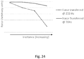
- the compression-side first flow path has a first inertance and the compression-side second flow path has a second inertance, and the first inertance is larger than the second inertance.
- the first inertance may be greater than the second inertance by a factor of at least 5 or at least 10. In certain embodiments, the first inertance is greater than the second inertance by a factor of no more than 100.
- a first TFmag of a first transfer function has at least one of a first global maximum and first local maximum at a first frequency
- a second TFmag of a second transfer function has at least one of a second global maximum and second local maximum at a second frequency
- the first transfer function describes a first relationship between pressure at a first point and pressure at a second point
- the second transfer function describes a second relationship between pressure at the second point and pressure at a third point
- the first point is located in one of: the pump, a port of the pump, and the compression-side first flow path
- the second point is located in the first internal volume (e.g., inside the first working chamber) of the compression-side accumulator
- the third point is located in the compression chamber of the actuator
- a first TFph of a first transfer function is equal to +/-90° at a first frequency
- the second frequency is higher than the first frequency.
- the second frequency may be greater than the first frequency by a factor of at least 5 or at least 20.
- the second frequency may be greater than the first frequency by a factor of less than 100.
- the first frequency is higher than a first lower limit and lower than a first upper limit, wherein the first lower limit is one of 0 Hz, 2 Hz, 5 Hz, or 10 Hz and the first upper limit is one of 100 Hz, 80 Hz, 60 Hz, 50 Hz, 30 Hz, 20 Hz, or 15 Hz.
- the second frequency is higher than a second lower limit and lower than a second upper limit, wherein the second lower limit is one of 100 Hz, 200 Hz, 300 Hz, 400 Hz, or 500 Hz and the second upper limit is one of 800 Hz, 1000 Hz, or 1500 Hz.
- the compression-side first flow path has a first length and the compression-side second flow path has a second length, and the first length is longer than the second length.
- the first length may be equal to at least 2 times or at least 5 times the second length.
- the first length is greater than the second length by a factor of no more than 50.
- compression-side first flow path comprises a first portion having a first cross-sectional area and the compression-side second flow path comprises a second portion having a second cross-sectional area, and the first cross-sectional area is larger than the second cross-sectional area (e.g., by a factor of at least 2 or at least 5, and/or by a factor of less than 100).
- the actuator further comprises an actuator piston having a first face at least partially exposed to fluid in the extension chamber and a second face at least partially exposed to fluid in the compression chamber.
- a piston rod may be physically attached to the piston (e.g., the piston rod may be physically attached to the first face of the piston).
- the compression-side first flow path has a first length that is less than the length of the compression flow path.
- the compression-side second flow path has a second length that is less than a length of the compression flow path.
- the sum of the first length and the second length is less than the length of the compression flow path.
- the compression flow path is the shortest flow path of a first set of one or more flow paths
- the compression-side first flow path is the shortest flow path of a second set of one or more flow paths
- the compression-side second flow path is the shortest flow path of a third set of one or more flow paths, wherein" the first set of one or more flow paths consists of each flow path of the hydraulic apparatus that fluidically couples the pump to the compression chamber; the second set of one or more flow paths consists of each flow path of the hydraulic apparatus that fluidically couples the pump to the first working chamber; and the third set of one or more flow paths consists of each flow path of the hydraulic apparatus that fluidically couples the first working chamber to the compression chamber.
- the compression-side accumulator is a type-2 accumulator.
- the compression-side accumulator comprises a first opening through the compression-side accumulator housing; a second opening through the compression-side accumulator housing; and an internal flow path fluidically coupling the first opening to the second opening, wherein the internal flow path is entirely contained in the first working chamber and wherein the compression flow path includes the internal flow path.
- the compression-side accumulator comprises a first tube comprising: a first tube housing comprising: a first outer surface and a first inner surface, the first inner surface defining a first bore, wherein at least a first portion of the first outer surface is exposed to fluid in the first working chamber of the compression-side accumulator.
- the compression-side accumulator comprises a second tube comprising: a second tube housing including a second outer surface and a second inner surface, the second inner surface defining a second bore, wherein at least a second portion of the second outer surface is exposed to fluid in the first working chamber of the compression-side accumulator.
- the second bore has a second cross-sectional area that is larger than a first cross-sectional area of the first bore (e.g., by a factor of at least 2 or at least 5, and/or by a factor of less than 100).
- the hydraulic apparatus further comprises an extension flow path fluidically coupling the pump to the extension chamber, and an extension-side accumulator comprising: an extension-side accumulator housing defining a second internal volume that is divided, by a second barrier (e.g., a movable barrier (e.g., a slidable piston , a bladder or portion thereof)), into a second contained chamber (e.g., a chamber containing a compressible fluid (e.g., a gas)) and a second working chamber, wherein: the second working chamber is fluidically coupled to the pump via an extension-side first flow path; and the second working chamber is fluidically coupled to the compression chamber via an extension-side second flow path.
- a second barrier e.g., a movable barrier (e.g., a slidable piston , a bladder or portion thereof)
- a second contained chamber e.g., a chamber containing a compressible fluid (e.g., a gas)
- the second working chamber
- the extension-side accumulator has a second stiffness and the compression-side accumulator has a first stiffness, wherein the second stiffness is greater than the first stiffness.
- the second stiffness may be equal to at least 5 times or at least 10 times the first stiffness.
- the second stiffness is greater than the first stiffness by a factor of less than 100.
- the first internal volume is larger than the second internal volume (e.g, by a factor of at least 2, by a factor of between 2 and 100).
- the extension-side accumulator may be a type-1 accumulator.
- the extension-side accumulator further comprises a cylindrical neck (e.g., having a diameter between 4-10mm and/or a length less than 5mm) that fluidically couples the second working chamber to the extension flow path.
- the extension-side first flow path may have a third length and the extension-side second flow path may have a fourth length, wherein the third length is less than the fourth length.
- the extension-side accumulator may be a type-2 accumulator.
- the extension-side first flow path may have a third length
- the extension-side second flow path may have a fourth length
- the third length may be greater than the fourth length.
- a third TFmag of a transfer function describing a relationship between pressure at a fourth point and pressure at a fifth point has at least one of a global maximum and local maximum at a third frequency, wherein the fourth point is located in one of: of the pump and the extension-side first flow path, and the fifth point is located in the second internal volume (e.g., inside the second working chamber or inside the second contained chamber).
- a third TFph of the third transfer function describing a relationship between pressure at a fourth point and pressure at a fifth point may be equal to +/-90° at a third frequency, wherein the fourth point is located in one of: the pump and the extension-side first flow path, and the fifth point is located in the second internal volume (e.g., inside the second working chamber or inside the second contained chamber).
- the third frequency is higher than the first frequency.
- the third frequency is larger than a third lower limit and lower than a third upper limit, wherein the third lower limit is 100 Hz and the third upper limit is 500 Hz.
- the third frequency is lower than the aforementioned second frequency.
- the compression-side accumulator housing may be directly physically attached to the actuator housing. In certain embodiments, the compression-side accumulator housing and the actuator housing may share at least a common portion (e.g., a common wall).
- the hydraulic apparatus may further comprise an outer housing that encircles at least a portion of the actuator housing.
- the hydraulic apparatus may include an annular cavity bounded on one side by an outer surface of the actuator housing or a portion thereof, and on another side by an inner surface of the outer housing or a portion thereof.
- at least one of the compression-side first flow path, the compression-side second flow path, the extension-side first flow path, and the extension-side second flow path includes at least a portion of the annular cavity.
- an inner diameter of the outer housing is at least 0.4 mm larger than an outer diameter of the actuator housing.
- a difference between the inner diameter of the outer housing and the outer diameter of the actuator housing is less than 1 mm.
- the annular cavity is separated a first volume and a second volume by an annular cavity (e.g., an o-ring).
- a removable insert is inserted into a portion of at least one of: the compression flow path, the extension flow path, the compression-side first flow path, the compression-side second flow path, the extension-side first flow path, and the extension-side second flow path.
- inserting the removable insert into the at least one flow path thereby changes one or more properties (e.g., a cross-sectional area, an inertance, and impedance, a restriction, etc.) of the at least one flow path.
- the removable insert may be a sleeve at least partially inserted into the annular housing, such that insertion of the sleeve into the annular cavity changes a cross-sectional area of the annular cavity.
- the sleeve may be in physical contact with at least a portion of an outside surface of the actuator housing. Additionally or alternatively, the sleeve may be in physical contact with at least a portion of an inside surface of the outer housing.
- the first barrier of the compression-side accumulator is an accumulator piston having a first surface at least partially exposed to fluid in the contained chamber and a second surface at least partially exposed to fluid in the working chamber.
- a first line normal to the second surface of the accumulator piston is parallel to a second line normal to at least one of the first face and second face of the actuator piston.
- the compression-side accumulator housing comprises a cylindrical portion having a first radial axis and a first longitudinal axis and the actuator housing comprises a second cylindrical portion having a second radial axis and a second longitudinal axis, and the first longitudinal axis and the second longitudinal axis are parallel.
- the compression-side accumulator includes a first compliant arrangement configured to provide a first degree of compliance responsive to a first internal pressure within the first internal volume.
- the first compliant arrangement may comprise, for example, a gas contained in the first contained chamber, and the first barrier may be moveable to compress or expand a volume of the first contained chamber.
- the compression-side first flow path comprises a first mass of fluid configured to resonate with the first compliant arrangement at a first resonance frequency.
- the first resonance frequency may vary responsive to variation of the first internal pressure.
- the compression-side second flow path comprises a second mass of fluid configured to resonate with the first compliant arrangement at a second resonance frequency. In certain embodiments, the second resonance frequency is higher than the first resonance frequency.
- extension-side accumulator comprises a second compliant arrangement in fluid communication with the second internal volume, a neck, and a third mass of fluid located in the neck, wherein the third mass is configured to resonate with the second compliant arrangement at a third resonance frequency (e.g., 5-100 Hz, 80-300 Hz).
- the second compliant arrangement comprises a gas contained in the second contained chamber, and the second barrier may be moveable to compress or expand a volume of the second contained chamber.
- the third resonance frequency may be higher than the first resonance frequency.
- the hydraulic apparatus contains fluid; the pump comprises a rotor, rotation of which at a constant speed for a given time generates pressure pulsations in at least a portion of the fluid of the hydraulic apparatus; the first compliant arrangement is arranged to at least partially absorb a first portion of said pressure pulsations; and the second compliant arrangement is arranged to at least partially absorb a second portion of said pressure pulsations.
- a first amplitude of the pressure pulsations at a first point is larger than a second amplitude of the pressure pulsations at a second point, wherein the first point is located in one of: the pump and the compression-side first flow path and the second point is located in the compression chamber of the actuator.
- a third amplitude of the pressure pulsations at a third point is larger than a fourth amplitude of the pressure pulsations at a fourth point; wherein the third point is located in one of: the pump and the extension-side first flow path and the fourth point is located in the extension chamber of the actuator.
- the hydraulic actuator of any of the disclosed hydraulic apparatuses described herein may further comprise a piston having a first face exposed to fluid in the compression chamber and a second face exposed to fluid in the extension chamber. Additionally, a piston rod may be attached to the second face.
- a vehicle comprising a suspension system including a hydraulic apparatus according to any embodiment described herein.
- the vehicle may comprise a plurality of the hydraulic apparatuses according to any of the embodiments disclosed herein.
- an accumulator comprising: a housing defining a first internal volume that is divided, by a barrier (e.g., a movable barrier (e.g., a slidable piston, a bladder or portion thereof)) into a first contained chamber (e.g., a chamber containing a compressible fluid (e.g., a gas)) and a first working chamber.
- the accumulator may further comprise a first tube having a first tube housing comprising a first outer surface, and a first inner surface defining a first bore, wherein at least a first portion of the first outer surface is exposed to fluid in the first working chamber of the compression-side accumulator.
- the accumulator may further comprise a second tube having a second tube housing comprising a second outer surface, and a second inner surface defining a second bore, wherein at least a second portion of the second outer surface is exposed to fluid in the first working chamber of the compression-side accumulator.
- the second bore has a second cross-sectional area that is larger than a first cross-sectional area of the first bore.
- the second cross-sectional area may be greater than the first cross-sectional area by a factor of at least 2 or at least 5, or by a factor of between 2-100 or 5-100.
- the first tube may have a first length and the second tube may have a second length that is less than the first length.
- a first ratio of the first length over the first cross-sectional area may be greater than a second ratio of the second length over the second cross sectional area.
- inertance of fluid in the first bore may be greater than inertance of fluid in the second bore.
- Such hydraulic systems have been utilized in, for example, active suspension systems of automobiles that, ideally, call for compact packaging, fast response times, and low noise operation.
- the inventors have discovered that even slight changes in relative arrangement of hydraulic components in integrated hydraulic systems may profoundly affect the operating properties (e.g., noise, response time) and packaging requirements of the overall system.
- a number of discoveries are described related to hydraulic components and specific arrangements of said hydraulic components in a hydraulic system, such that a combination of compact packaging, fast response times, and low-noise operation may be achieved. These discoveries include, for example, incorporation of various types of accumulators located at different parts in the hydraulic systems, as well as precise tuning of, for example, relative impedances, inertances, and/or lengths of various flow paths of the hydraulic systems.
- a hydraulic system such as, for example, a hydraulic system utilizing a hydraulic actuator
- noise, response time, and packaging size associated with the hydraulic system, often in ways that are not readily predictable using a-priori information.
- these considerations may represent trade-offs; for example, adding components such as noise absorbers may serve to mitigate acoustic noise, but may add bulk to the system and/or increase response time, thereby precluding certain applications in which space is highly limited and/or very fast response times are desired.
- various hydraulic systems, and methods of use thereof that may allow for one or more of low noise, fast response-time operation, while permitting flexibility and compactness in packaging.
- the various embodiments described herein should not be limited to providing these exemplary benefits and other possible benefits are also possible.
- an accumulator in a hydraulic system including a hydraulic actuator and a pump, an accumulator may be incorporated for absorbing pulsations or vibrations, such as vibrations that may lead to noise, in the system.
- the accumulator may include a working chamber that is fluidically coupled to the pump by a first flow path and fluidically coupled to a compression chamber of the actuator by a second flow path.
- performance metrics such as, for example, noise attenuation capability and/or response-time
- noise attenuation may be improved in a system in which inertance of the first flow path is greater than inertance of the second flow path. Additionally or alternatively, noise attenuation may be improved by designing a hydraulic system such that a resonance associated with interaction of inertance in the first flow path and compliance of the accumulator occurs at a first frequency of less than 90 Hz (e.g., at a frequency range of 1-90Hz, 1-50 Hz, or 1-20 Hz.
- the second flow path may be configured such that a resonance associated with interaction of inertance in the second flow path and compliance of the accumulator occurs at a second resonance frequency that is greater than the first frequency.
- resonance frequencies of a system may be determined or evaluated empirically through the use of transfer functions.
- two accumulators may be utilized and configured such that they interact in a synergistic manner.
- a compression-side accumulator may be located on the compression-flow path that fluidically couples the pump and a compression chamber of the actuator, while an extension-side accumulator may be located on the extension-flow path that fluidically couples the pump to an extension chamber.
- each accumulator on either side of the pump may result in system performance (e.g., pulsation attenuation capability) that far outperforms the sum of the individual accumulators considered alone.
- system performance e.g., pulsation attenuation capability
- Further synergy may arise by configuring one of the accumulators (e.g., the extension-side accumulator) to have a stiffness greater than that of the other accumulator (e.g., the compression-side accumulator) and/or by sizing one of the accumulators (e.g., the extension-side accumulator) such that it has an internal volume smaller than that of the other accumulator (e.g., the compression-side accumulator),
- the compression-side accumulator may include two distinct ports-a first port and a second port-- through which fluid may ingress/egress a working chamber of compression-side accumulator (for example, the compression-side accumulator may be a type-2 accumulator as described herein).
- the inventors have recognized that additional benefits may arise with respect to system performance by precisely controlling various properties (e.g., a first inertance, a first impedance, a first length, a first cross-sectional area) of a compression-side first flow path, or a portion thereof , fluidically coupling the pump to the first accumulator port relative to the respective properties (e.g., a second inertance ,a second impedance, a second length, a second cross-sectional area) of a compression-side second flow path, or portion thereof, fluidically coupling the second accumulator port to the compression chamber of the actuator.
- various properties e.g., a first inertance, a first impedance, a first length, a first cross-sectional area
- the respective properties e.g., a second inertance ,a second impedance, a second length, a second cross-sectional area
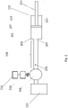
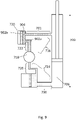
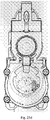
- Fig. 2 illustrates a simplified embodiment of a hydraulic actuator 212.
- the hydraulic actuator 212 includes (i) a compression chamber 201 defined by a cylindrical housing 205 and a first face of a slidable piston 207 inserted into the housing 205, and (ii) a extension chamber 220 defined by a second face of the slidable piston 207 and the housing 205.
- the second face of the slidable piston 207 may be physically attached to a piston rod 209.
- the housing 205 further comprises a receiving port 203, which may be, for example, an opening through the housing 205 that allows fluid to ingress or egress the compression chamber 201.
- the compression chamber 201 may be fluidically coupled to a pump 206 by a receiving flow path 208, which may be, for example, a tube, hose, pipe, or channel.
- the pump in turn, may be fluidically coupled to a fluid reservoir 210.
- An electric motor 218, in communication with a motor controller 216, may be operatively coupled to the pump 206.
- a torque applied to the pump 206 by the electric motor 218 may be intentionally varied with time in order to vary a pressure of fluid in the compression chamber 201, thereby imparting a force onto the piston 207 that may result in movement of the piston 207 and attached piston rod 209, and may cause a length 214 of the hydraulic actuator to change.
- a motor controller 216 may receive a nominal command profile (e.g., from an external controller or a user) that specifies, for example, any one of: a desired length 214 of the actuator 212 over a given time (i.e., a "nominal command length profile”), a desired longitudinal position of the piston over a given time (i.e., a "nominal command position profile”), a desired pump velocity over a given time (i.e, a "nominal command velocity profile”), a desired force to apply to the first face of the piston 207 over a given time (i.e., a "nominal command force profile"), a desired pressure of the compression chamber 201 over a given time (i.e., a "nominal command pressure profile”), or a desired torque to apply to the pump 206 over a given time (i.e., a "nominal command torque profile”).
- a nominal command profile e.g., from an external controller or a user
- the motor controller 216 may apply a time-dependent signal (e.g., an electrical signal (e.g., a current, a voltage)) to the motor 218 such that the pump and/or actuator behaves according to the nominal command profile.
- a time-dependent signal e.g., an electrical signal (e.g., a current, a voltage)
- the aforementioned equations are examples and such equations may be modified to incorporate additional parameters, such as, for example, inertia of the pump, drag torque, friction of various components, leakage around the pump, etc.
- the pump 206 may be a positive displacement hydraulic pump.
- the flow rate of fluid discharged by a positive displacement pump may not be smooth, but rather may fluctuate at a frequency referred to as a "ripple frequency.”
- Such fluctuations in discharge flow rate that originate at a pump 206 (referred to herein as “flow ripple") may generate pressure fluctuations that may propagate downstream in a hydraulic system as pressure waves (sometimes referred to as acoustic waves), thereby resulting in fluctuations in pressure differential at various points in the hydraulic system.
- Fig. 3 depicts an example of a pressure profile that may be observed at a first point 200 of the hydraulic system of shown in Fig. 2 .
- the observed pressure 301 at the first point 200 in the hydraulic system fluctuates according to the command pressure profile 303 (which specifies desired pressure as a function of time) superimposed with higher frequency fluctuations 305 that arise due to flow ripple generated by the pump 206.
- the high frequency fluctuations 305 in observed pressure 301 that arise due to flow ripple may be referred to as "pressure ripple.”
- ripple may refer to flow ripple, pressure ripple, or force ripple, as all aforementioned phenomena are interrelated and may share a common origin (e.g., operation of a positive displacement pump).
- Fig. 4 illustrates the use of a hydraulic accumulator 402.
- the hydraulic system of Fig. 4 is similar to that of Fig. 2 , with the addition of an accumulator 402 that has been located on the receiving flow path.
- An accumulator 402 may include a housing 416 that defines an internal volume 401.
- the internal volume 401 may be separated, by a barrier 406, into a contained chamber 408 and a working chamber 410.
- a first side of the barrier 406 is exposed to a compressible fluid (e.g., a gas) contained in the contained chamber 408, and a second side of the barrier 406 is exposed to hydraulic liquid in the working chamber 410.
- a compressible fluid e.g., a gas
- the compressible fluid in the contained chamber 408 may be separated from the working chamber by the barrier.
- the barrier 406 may be movable.
- a pressure pulsation may result in instantaneous pressure of fluid in the receiving chamber exceeding the pressure of the contained chamber.
- fluid may flow from the receiving flow path 208, through the port 450, and into the working chamber 410, potentially resulting in movement (e.g., sliding or flexing) of the barrier 406 such that the volume of the working chamber 410 increases while the volume of the contained chamber 408 contracts; due to contraction of the volume of the contained chamber, the compressible fluid in the contained chamber 408 may subsequently exert a restoring force on the barrier 406.
- the restoring force may cause the barrier 406 to move back to its original position simultaneously as fluid flows out of the working chamber 410 through the port 450.
- the compliance provided by the compressible fluid in the contained chamber may allow for pulsations to be at least partially absorbed by the accumulator.
- the barrier 406 is a floating piston and the housing 416 is cylindrical.
- the housing 416 may be any shape including spherical and semispherical, and the barrier 406 may be any barrier, such as, for example, an elastomeric or semi-elastomeric bladder, that separates fluid in the contained chamber 408 from fluid in the working chamber 410.
- the accumulator housing 416 comprises a single port 450 through which fluid may egress/ingress the working chamber 410 to/from the receiving flow path 208.
- a type-1 accumulator An accumulator in which fluid may egress and ingress the working chamber 410 through a single port 450 (as opposed to multiple ports) is referred to herein as a type-1 accumulator.
- the hydraulic accumulator 402 of Fig.4 may therefore be said to be a type-1 accumulator.
- hydraulic accumulators can be provided in various configurations including but not limited to hydraulic gas charged accumulators (wherein the contained chamber 408 includes a gas) and spring hydraulic accumulators (wherein the barrier 406 is physically restrained via a spring). While many of the embodiments described herein depict hydraulic gas accumulators, the current disclosure is not limited in this fashion of accumulators except as explicitly stated. It is understood that, unless otherwise stated, the various systems described herein may correspond to any appropriate type of accumulator. It is understood that other terms know in the art, depending on context, may be used interchangeably with accumulator, such as, for example, a buffer and a reservoir.
- a transfer function is understood to mean a function that describes how changes in an observed operating parameter at a second point in a system are related to changes in an operating parameter at a first point in the system.
- the observed operating parameter at the second point may be referred to as, for example, an "output" and may correspond to, for example, an observed pressure, a force applied to the piston, a displacement position, etc.
- the change at the first point may be referred to as, for example, an "input” (such as “input ripple”) and may correspond to, for example, a pressure ripple at first point, a displacement, etc.
- Response of hydraulic systems to input ripple generally may depend on the frequency of the input ripple.
- a transfer function may be represented as a plot depicting, on the y-axis, a ratio (or log ratio) of intensity or amplitude of the output to intensity or amplitude of the input and, on the x-axis, frequency of the input (e.g. input ripple).
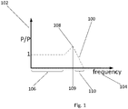
- Fig. 1 depicts an example of a transfer function 100.
- the y-axis 102 corresponds to a ratio of intensity (or amplitude of , for example, pressure fluctuations observed at a second point 404 of the hydraulic system of Fig. 4 to intensity or amplitude of, for example, the pressure fluctuations observed at a first point 200 of the hydraulic system of Fig. 4 .
- the first point 200 is located in the receiving flow path 208 between the pump 206 and the accumulator 402
- the second point 404 is located in the working chamber 404 of the accumulator 402.
- these points are merely exemplary, and in general a transfer function may describe transfer of, or a relationship between, pulsations between any two points in a system.
- the x-axis 104 may correspond to frequency of the pressure fluctuation at the first point 200. If a pressure fluctuation at a given frequency propagates from the first point 200 to the second point 404 with no attenuation nor amplification, then the transfer function 100 would be 1 at that given frequency (that is, the intensity or amplitude of the pressure when it reaches the second point 404 would be equal to the initial intensity or amplitude of the pressure at the first point 200). For a fluctuating pressure that is attenuated during propagation from the first point 200 to the second point 404, or for a pressure wave where the energy is partially directed to an alternate flow path that does not pass through the second point 404, the transfer function 100 may be less than 1. For pressure fluctuations that are amplified during propagation, the transfer function 100 may be greater than 1.
- Transfer functions may also be illustrated in a graph where the y-axis 102 may be represented as a log of the ratio of output intensity to input intensity.
- a zero value indicates no attenuation and no amplification during propagation of an input pressure from a first point to a second point; a negative value indicates attenuation during propagation; and a positive value indicates amplification during propagation.
- the exemplary transfer function illustrated in Fig. 1 illustrates a hypothetical response of pressure at the second point 404 (the output) of the hydraulic system in response to pressure fluctuations at a first point 200 (the input) of the hydraulic system-the ratio along the y-axis therefore represents pressure intensity or amplitude over pressure intensity or amplitude.
- pressure/pressure transfer functions in which a relationship of pressure at one point to pressure at another point is described, may be referred to as "pressure/pressure transfer functions.”
- the y-axis may represent ratios of intensity or amplitude of any parameter at the output over intensity or amplitude of another parameter at the input.
- the y-axis may correspond to a ratio of (a) intensity of an observed pressure wave at the second point 404 of the hydraulic system over (b) intensity of fluctuating fluid displacements (referred to as displacement ripple) determined at a first point 200 of the hydraulic circuit.
- the ratio is of pressure intensity or amplitude at the output over displacement at the input, and the transfer function is referred to as a pressure/displacement transfer function.
- a transfer function may be obtained by plotting, on the y-axis, a ratio of (a) the position of the barrier 406 (or other moveable component) of the accumulator 402 to (b) fluctuations in pressure at the first point 200 of the hydraulic system; in these embodiments, the ratio is of displacement at the output over pressure intensity or amplitude at the input.
- the exemplary magnitude of the pressure/pressure transfer function illustrated in Fig. 1 corresponds to transfer (or propagation) of pressure pulsations (sometimes referred to as pressure waves or as pressure pulsations) between the first point 200 of Fig. 4 to the second point 404 of Fig. 4 .
- the first point 200 is located in the flow passage in between the pump 206 and the accumulator 402, while the second point 404 is located within the working chamber 410 of the accumulator 402.
- the transfer function 100 illustrated in Fig. 1 the transfer function 100 is flat and equal to 1 for a lower range of frequencies 106, indicating that a pressure wave at a frequency within the lower range of frequencies 106 is transferred without mitigation to the second point 404.
- the transfer function then reaches a maximum 108 at a specific frequency 109 that may be referred to as a "resonance frequency" (which may be, for example, a Helmholtz resonance frequency).
- a resonance frequency may be indicated by a minimum instead of a maximum.
- a transfer function may be generated that describes the phase of a wave (e.g., pressure wave, or fluctuation) at a given frequency observed at one point in the hydraulic system as compared to the phase observed for the same frequency at another point in the hydraulic system.
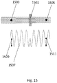
- Fig. 15 depicts a hypothetical hydraulic system comprising ahydraulic element 1501. As shown in Fig.
- a pressure wave or fluctuation 1507 generated at a first point 1503 in the hydraulic system propagates through the hydraulic element 1501 to a second point 1505 (that is, the pressure wave or fluctuation is transferred from the first point to the second point).
- a pressure wave or fluctuation 1507 generated at a first point 1503 in the hydraulic system propagates through the hydraulic element 1501 to a second point 1505 (that is, the pressure wave or fluctuation is transferred from the first point to the second point).
- the intensity or amplitude 1509 of the pressure wave 1507 at the first point 1503 is equal to the intensity or amplitude 1511 of the pressure wave 1507 at the second point 1505, so a magnitude of a pressure/pressure transfer function plotting the log ratio of the amplitude 1511 of the pressure wave 1507 at the second point 1505 to the amplitude 1509 of the pressure wave 1507 at the first point 1503 would be equal to zero (indicating propagation without attenuation or amplification) for the specific frequency of wave shown.
- the phase of the transfer function describing propagation from the first point 1503 to the second point 1505 would be equal to +/-180° for the specific frequency of wave shown.
- TFmag of a transfer function
- TFph the phase of a complex function
- the TFmag of a transfer function describing a relationship between pressure at a first point and pressure at a second point may be represented as a plot having two axes (e.g., an x-axis and a y-axis) in which the first axis (e.g., x-axis) depicts frequency of pressure fluctuations and the second axis (e.g., y-axis depicts) a ratio (or log-ratio) of amplitude of pressure fluctuations at the second point to amplitude of pressure fluctuations at the first point.
- the TFph of a transfer function describing a relationship between pressure at a first point and pressure at a second point may be represented as a plot having two axes (e.g., an x-axis and a y-axis) in which the first axis (e.g., x-axis) depicts frequency of pressure fluctuations and the second axis (e.g., y-axis) depicts the phase angle of the transfer function (e.g., a difference between the phase of pressure fluctuations at the second point as compared to the phase of pressure fluctuations at the first point).
- Phase difference is understood to refer to a difference in the phase of pressure fluctuations as observed at one point in a hydraulic system compared to the phase of the pressure waves as observed at another point in the hydraulic system.
- the TFph of a transfer function describing a relationship between pressures at the two points may have a value of + / - 90° at the resonance frequency of that portion of the system.
- the TFmag of the transfer function may have a local maximum or global maximum at the resonance frequency of that portion of the system.
- the resonance frequency may be determined by evaluating the TFph to determine a frequency (or frequency range) at which the observed phase difference is + / - 90°.
- resonance frequency may refer to, for example, (i) a frequency at which a TFmag of a pressure/pressure transfer function shows either a global maximum or local maximum (i.e., a frequency at which the first derivative of the transfer function with respect to frequency changes from a positive value to zero or from a positive value to a negative value), or (ii) a frequency at which a TFph is equal to + / - 90°.
- the pulsations may "excite" one or more resonances in the system.
- resonance may be thought of as occurring when an inertial element of the hydraulic system (for example, a portion of the fluid in a volume of the hydraulic system) physically oscillates synchronously with a compliant element (e.g., a gas contained in the contained chamber of an accumulator, a spring) of the system, such that there exists a continuous exchange between potential energy (e.g., energy stored by compression or extension of the compliant element) and kinetic energy (e.g., due to movement of the portion of fluid).
- potential energy e.g., energy stored by compression or extension of the compliant element
- kinetic energy e.g., due to movement of the portion of fluid
- a hydraulic system featuring a plurality of inertial and compliant elements may exhibit various resonances. If two or more of these various resonances have overlapping or sufficiently similar frequencies, then a first resonance of the hydraulic system may 'excite' a second resonance of the hydraulic system in an uncontrollable or undesirable manner. Therefore, inventors have recognized the importance of designing the system such that various resonances are sufficiently spaced apart in resonance frequency, as will be discussed throughout this application.
- a resonance frequency of a given hydraulic system may be determined, for example, by: (i) locating pressure sensors at various points in the hydraulic system, (ii) introducing pressure waves or pulsations having a first frequency into the system, (iii) monitoring the intensity, amplitude, and/or phase of the pressure wave or pulsations at each of the various points in the system, (iv) varying the frequency of the generated pressure waves or pulsations while continuing to monitor the intensity, amplitude, and/or phase of the pressure wave or pulsations at each of the various points in the system, (v) determining TFmag and/or TFph of one or more transfer functions describing the relationship between pressures at the various points, and(vi) identifying frequencies where the TFph is +/-90° and/or the TFmag has a global or local maximum.
- the transfer function decreases below 1, indicating that a pressure fluctuation with a frequency in the second range will either be attenuated during propagation or will follow an alternate flow path that does not pass through the second point 404.
- the hydraulic actuator 212 may have a high fluidic impedance as compared to the accumulator 402.
- pressure pulsations may propagate to the working chamber 410 of the accumulator 402, causing the barrier 406 to move up and down in response to the pressure pulsations, thereby at least partially absorbing their energy and, for example, converting it to heat energy (via, for example, heating of the gas particles in the contained chamber 408).
- low frequency input pressure pulsations may propagate into the working chamber 410 of the accumulator 402, and, in certain cases, may be absorbed by the accumulator 402.
- Pressure fluctuations with a frequency at or substantially near the resonance frequency 109 may be amplified between the first point 200 of Fig. 4 to the second point 404 of Fig. 4 -a phenomenon that may be referred to as "Helmholtz" type resonance -resulting in a local maximum 108 in the TFmag at the resonance frequency 109.
- pressure fluctuations with a frequency in a second range 110 higher than the resonance frequency 109 may not be able to overcome inertia associated with movement of the barrier 406 and/or inertia associated with movement of fluid in the neck 452 of the accumulator.
- a typical Tfmag of a transfer function may follow the general pattern of Fig. 1 (e.g., a relatively flat portion initial corresponding to low frequency range 106, a maximum 108 corresponding to a resonance frequency 109, and a negative slope in a second range of frequencies 110).
- a type-1 accumulator e.g., an accumulator 402 that branches off the flow path 208 via a neck 452
- a type-1 accumulator may become progressively less effective at absorbing fluctuations (e.g. ripple) as frequency increases above a resonance frequency 109 of the portion of the system.
- fluctuations e.g. ripple
- the effectiveness of the accumulator 402 may diminish to such a degree that response of the overall hydraulic system may approach that of a similar hydraulic system with no accumulator.
- a type-2 accumulator may result in more effective attenuation properties over a wider range of frequencies that afforded by a type-1 accumulator.
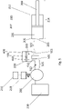
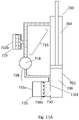
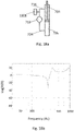
- Fig. 5 illustrates use of a type-2 accumulator.
- a type-2 accumulator may include an accumulator housing 416 at least partially defining an internal volume that is separated by a movable barrier 406 into a contained chamber 408 and a working chamber 410.
- the accumulator housing 416 may include two distinct ports:(i) a first port 501through which fluid may ingress/egress the working chamber 410, and (ii) a second port 502 through which fluid may also ingress/egress the working chamber 410. Furthermore, the first port and second port may be fluidically coupled by an internal flow path that may be located within the working chamber 410.
- the first port 501 allows fluid to ingress/egress the working chamber 410 from/to a first flow path 505 that fluidicially couples the pump 206 to the working chamber 410
- the second port allows fluid to ingress/egress the working chamber 410 from/to a second flow path 507 that fluidically couples the working chamber 410 to the compression chamber 201 of the hydraulic actuator 212
- At least two distinct, non-overlapping flow paths may exist through which fluid may ingress/egress the working chamber 410 of the accumulator 500.
- An overall flow path between the pump 206 and the compression chamber 201 of the hydraulic actuator 212 therefore includes the first flow path 505, the working chamber 410 of the accumulator, and the second flow path 507.
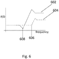
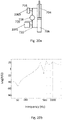
- Fig. 6 illustrates the plot of TFmag 602 of a first pressure/displacement transfer function describing the relationship of pressure observed at a first point 552, located in the first flow path 505, to a displacement ripple generated at the pump 206.
- Fig. 6 further illustrates TFmag 604 of a second pressure/displacement transfer function describing to the relationship of pressure observed at a second point 550, located inside of the working chamber 410 of the accumulator 500, to the displacement ripple generated at the pump 206.
- propagation of fluctuations e.g.
- Tfmag 604 of the second transfer function may depict a local minimum at a second resonance frequency 606 that is higher (i.e., is at a higher frequency) than a first resonance frequency 608 depicted, as a local minimum, in TFmag 602 of the first transfer function.
- the difference between the first resonance frequency 608 and the second resonance frequency 606 may result from the inertial mass associated with fluid within the first flow path 505.
- points downstream of the accumulator 500 may respond as if it they are being excited not by the displacement ripple or pressure fluctuations generated at the pump 206, but rather by the attenuated pressure ripple that has reached the working chamber 410.
- the exemplary type-2 accumulator 500 includes two ports (the first port 501 and second port 502), each of which is in fluid communication with a first flow path 505 and a second flow path 507, respectively.
- fluid in the first flow path 505 may interact with the compliance of the accumulator to exhibit a first resonance (e.g., a first "Helmholtz" type resonance, wherein a portion of fluid in the first flow path 552 oscillates synchronously with the compliant arrangement of the accumulator 500) at a first resonance frequency that depends at least in part on a first mass of fluid (or first inertance) in the first flow path 505 and/or the stiffness of the accumulator 500, while fluid in the second flow path 507 can interact with the compliance of the accumulator 500 to exhibit a second resonance (e.g., a second "Helmholtz" type resonance, wherein a portion of fluid in the second flow path 507 oscillate
- a first resonance e.g., a first "He
- a type-1 accumulator 402 such as that shown in Fig. 4 , includes only a single port 450 through which fluid may ingress/egress the working chamber 410 of the accumulator and may therefore exhibit only a single fundamental resonance; this resonance may be determined by the fluid in the neck 452 (i.e., a volume having a smaller cross-sectional area than the internal volume of the accumulator that directly fluidically couples the accumulator to the receiving flow path 208) or a portion thereof oscillating synchronously with the complaint arrangement of the accumulator 402, and this resonance frequency may depend on, for example: the cross sectional area of the neck 452, the length of the neck 452, the compliance or stiffness of the accumulator 500, and/or the physical properties (e.g., compressibility, density) of the fluid in the neck 452.
- the fluid in the neck 452 i.e., a volume having a smaller cross-sectional area than the internal volume of the accumulator that directly fluidically couples the accumulator to the receiving flow path 208 or
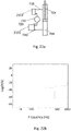
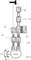
- an actuator 700 comprises an actuator housing 702 into which a piston 708 is slidably received.
- a first face 710 of the piston 708 is exposed to fluid in a compression chamber 706, while a second face 712 of the piston 708 is exposed to fluid in an extension chamber 704.
- a piston rod 714 may be physically attached to the second face 712 of the piston 708. In alternate embodiments, the piston rod 714 may be physically attached to the first face 710 of the piston 708.
- the piston rod 714 may allow, in certain conditions, for the actuator to apply a force to an external structure (e.g., a vehicle body (not shown)) that may be attached to the piston rod 714.
- an external structure e.g., a vehicle body (not shown)
- the piston rod may be attached to the vehicle body through an intervening top-mount (not shown).
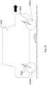
- the illustrated hydraulic system also includes a compression flow path 724 (indicated by dashed horizontal lines) fluidically coupling the compression chamber 706 to the pump 718.
- the compression flow path 724 may, in certain conditions, permit fluid to flow between the pump 718 and the compression chamber 706 of the actuator.
- the pump may be utilized to drive fluid to the compression chamber 706, thereby effecting a force on the first face 710 of the piston and allowing for controlled extension of the piston rod 714.
- the compression flow path may include, for example: (i) a compression-side accumulator 726, (ii) a compression-side first flow path 728 fluidically coupling the pump 718 to a compression-side working chamber 738a of the compression-side accumulator 726, and (iii) a compression-side second flow path 730 fluidically coupling the compression-side working chamber 738a of the compression-side accumulator 726 to the compression chamber 706 of the actuator 700.
- the compression-side accumulator 726 is located fluidically between the pump 718 and the compression chamber 706, and, in addition to serving other functions, may at least partially attenuate pulsations generated at the pump prior to said pulsations reaching the compression chamber 706.
- the illustrated hydraulic system further comprises an extension flow path 716 (indicated by gray diagonal hatch marks) fluidically coupling the extension chamber 704 of the actuator 700 to the pump 718.
- the extension flow path 716 may, in certain conditions, permit fluid to flow between the pump 718 and the extension chamber 704 of the actuator.
- the pump may be utilized to drive fluid to the extension chamber 704, thereby effecting a force on the second face 712 of the piston and allowing for controlled contraction of the piston rod 714.
- the extension flow path may include: (i) an extension-side accumulator 720, (ii) a extension-side first flow path 722 fluidically coupling the pump 718 to the extension-side working chamber 738b of the extension-side accumulator 720, and (iii) an extension-side second flow path 701 coupling the extension-side working chamber 738b of the extension-side accumulator 620 to the extension chamber 704 of the actuator 700.
- the extension-side accumulator 720 is located fluidically between the pump 718 and the extension chamber 704, and, in addition to serving other functions, may at least partially attenuate pulsations generated at the pump prior to said pulsations reaching the extension chamber 704.
- the bidirectional pump is a variable speed pump, such that pressure difference and/or flow rate between the compression chamber and extension chamber of the actuator may be precisely controlled using the pump.
- the pump 718 may comprise a rotor that includes, or is mechanically coupled to, one or more displacement elements (not pictured).
- application of appropriate torque to the rotor may cause rotation of the rotor, thereby generating a pressure difference and/or fluid flow across the pump 718.
- rotation of the rotor may also generate pressure pulsations (ripple) as described in Fig. 3 and the accompanying description herein.
- the pressure difference across the pump, flow rate across the pump, and/or frequency of the pressure pulsations may depend at least in part on an angular speed at which the rotor is rotated and/or a magnitude of torque applied to the rotor.
- the compression flow path 724, compression-side first flow path 728, compression-side second flow path 730, extension flow path 716, extension-side first flow path 722, and/or extension-side second flow path 701 may comprise additional hydraulic components such as, for example, one or more valves (e.g., variable flow valves, solenoid valves, on/off valves, three way valves, etc.), restriction orifices, or other hydraulic components through which, under appropriate circumstances (e.g., appropriate fluid pressure and/or opening of said valves), fluid may flow. Additionally or alternatively, in certain embodiments a length of the compression flow path 724 may exceed a length of the extension flow path 716. In certain embodiments, the length of the compression flow path 724 may be larger than the length of the extension flow path by a factor of at least 2.
- each of the compression-side accumulator 726 and the extension-side accumulator 720 comprises a housing 733a and 733b, respectively, defining an internal volume 732a and 732b, respectively, with the internal volume being separated, by a barrier 736a and 736b, respectively (e.g., a piston or bladder), into a contained chamber 734a and 734b, respectively and a compression-side and an extension side working chamber 738a and 738b, respectively.
- a barrier 736a and 736b respectively (e.g., a piston or bladder)
- each of the compression-side accumulator 726 and extension-side accumulator 720 further comprises a single port 735a and 735b, respectively, defined as an opening through the housing 733a and 733b, respectively, through which fluid may ingress/egress the compression-side working chamber 738a and 738b, respectively.
- Each of the illustrated compression-side accumulator 726 and extension-side accumulator 720 may therefore be classified as type-1 accumulators.
- the compression-side accumulator 726 may be a type-1 accumulator or a type-2 accumulator.
- the extension-side accumulator 720 may be a type-1 accumulator or a type-2 accumulator.
- a net force applied to the piston 708 is equal to the difference of a first force applied to the first face 710 of the piston 708 due to pressure of fluid in the compression chamber 706 and a second force applied to the second face 712 of the piston 708 due to pressure of fluid in the extension chamber 704.
- displacement ripple generated at the pump 718 may propagate through the compression flow path 724 to result in pressure fluctuations (pressure ripple) in the compression chamber 706, and/or may propagate through the extension flow path 716 to result in pressure fluctuations (pressure ripple) in the extension chamber 704.
- the inventors have recognized that, as long as displacement ripple can propagate through at least one of the compression flow path 724 and the extension flow path 716 and reach the compression and or extension volumes, the net force applied on the piston 708 may fluctuate accordingly. That is, even if the ripple is completely attenuated through one of the aforementioned flow paths, if the ripple is able to propagate through the other flow path then the net force on the piston may fluctuate (e.g., force ripple will occur), possibly causing the position of the piston to fluctuate or vibrate uncontrollably and undesirably.
- each accumulator located and configured on opposite sides of the pump, such that propagation of input ripple through both the compression flow path 724 and the extension flow path 716 from the pump may be at least partially or sufficiently mitigated, and in some instances substantially eliminated, for at least some ripple frequencies or frequencies within within a given frequency range.
- size or relative size of the compression-side accumulator 726 and/or extension-side accumulator 720 may affect behavior of the system.
- decreasing the size of one or both of the internal volumes 732a and 732b of the compression-side accumulator 726 and/or extension-side accumulator 720, respectively, and/or increasing the stiffness of one or both of the accumulators may increase a resonance frequency associated with the respective accumulator(s), thereby increasing the range of frequencies at which ripple is attenuated during propagation through the compression flow path 725 and/or extension flow path 716.
- the size and/or stiffness of one or both of the accumulators such that expansion of fluid in the system due to changing temperature , as well as displacement of fluid caused by insertion of the piston rod into the actuator housing during compression, may be readily accommodated by one or both of the accumulators.
- increasing stiffness of an accumulator may increase the range of frequencies at which pulsations are attenuated, such increased stiffness may correspondingly decrease the magnitude of pulsation attenuation that is achieved by the accumulator.
- the aforementioned trade-offs may be resolved by designing the system such that (a) one of the compression-side accumulator and extension-side accumulator has an internal volume that is substantially larger than the internal volume of the other accumulator, and/or (b) one of the accumulators is substantially stiffer than the other accumulator.
- This trade-off permits effective mitigation of ripple while maintaining overall response of the system.
- the internal volume 732a of the compression-side accumulator 726 is larger than the internal volume 732b of the extension-side accumulator 720 and/or the extension-side accumulator 720 is stiffer than the compression-side accumulator 726.
- extension of the actuator 700 may result in fluid flowing from the extension chamber 704 to either the extension-side accumulator 720 or through the pump 718.
- compression of dampers of a suspension system may occur at a maximum velocity that is faster than extension of the dampers.
- Very rapid compression of the actuator 700 may result in high fluid velocities through the pump 718, and may cause the pump 718 to rotate at velocities above design specifications, possibly damaging the pump 718 or resulting in degradation in ride quality.
- Increasing the size of the internal volume 732a of the compression-side accumulator 726 may increase the fluid holding capacity of the compression-side accumulator 726, such that, during compression events, more fluid flows to the compression-side accumulator 726 and less fluid flows through the pump 718, thereby potentially protecting components of the pump from overly rapid rotation and potentially allowing for improved ride quality during high speed compression events.
- the internal volume 732a of the compression-side accumulator 726 may be larger than the internal volume 732b of the extension-side accumulator 720 by a factor of at least 2.
- the compression-side accumulator 726 has an internal volume 732a between 8 cubic inches and 13 cubic inches
- the extension-side accumulator 720 has an internal volume 732b between 2.5 and 5 cubic inches, although embodiments outside these ranges are also contemplated to be within the scope of the present disclosure.
- the internal volume of an accumulator is understood to mean a sum of the volume of the contained chamber 734a or 734b, the volume of the barrier 736a or 736b, respectively, and the volume of the compression-side working chamber 738a or 738b, respectively.
- the hydraulic system may be designed such that the internal volume 732b of the extension-side accumulator 720 is larger than the internal volume 732a of the compression-side accumulator 726.
- the stiffness of the extension-side accumulator 720 may be at least 5 times the stiffness of the compression-side accumulator 726.
- "Stiffness" of an accumulator is understood to refer to a ratio of the magnitude of a force exerted on the barrier 406 of an accumulator or a portion thereof to the change in a physical dimension of the contained chamber 408..
- the stiffness of an accumulator (and therefore the compliance and/or associated resonance frequency) having a compliant arrangement that includes a compressible fluid (e.g., gas) contained in a contained chamber, as disclosed herein, may vary responsive to internal pressure of the compressible fluid and/or the volume of the contained chamber according to various thermodynamic principles (e.g.
- the stiffness of the extension-side accumulator 720 may be at least 5 times or at least 10 times the stiffness of the compression-side accumulator 726.
- the compression-side accumulator may have a stiffness between 1E10 Pa/m ⁇ 3 to 1E11 Pa/m ⁇ 3, and/or the extension-side accumulator may have a stiffness between 1E11- Pa/m ⁇ 3 to 1E12 Pa/m ⁇ 3. Embodiments having values outside of these specific ranges are also contemplated to be within the scope of the present disclosure.
- a flow path fluidically coupling the compression chamber 706 of the actuator 700 to the compression-side working chamber 738a of the compression-side accumulator 726 may be shorter (i.e., have a shorter length) than a flow path fluidically coupling the compression chamber 706 of the actuator 700 to the pump 718 (e.g., the compression-side second flow path 730 may be shorter than the compression flow path 724, as is shown in Fig. 7 ).
- a flow path fluidically coupling the extension-side working chamber 738b of the extension-side accumulator 720 to the extension chamber 704 of the actuator 700 may be shorter (i.e., have a shorter length) than a flow path fluidically coupling the pump 718 to the extension chamber 704 of the actuator 700 (e.g., the extension-side second flow path 701 may be shorter than the extension flow path 716, as is shown in Fig. 7 ).
- At least one of the compression-side accumulator 726 and the extension-side accumulator 720 may be a type-2 accumulator.
- a hydraulic system comprising two accumulators wherein at least one of the accumulators is a properly configured and positioned type-2 accumulator may exhibit enhanced ripple attenuation between the pump and the actuator piston over an extended frequency range, at least as compared to a similar system in which none of the accumulators are a type-2 accumulator.
- Fig. 8 depicts an embodiment of a hydraulic system in which the compression-side accumulator 726 is a type-2 accumulator, and the extension-side accumulator 720 is a type-1 accumulator.
- the compression-side accumulator 726 includes a first port 802 that allows fluid to ingress/egress the compression-side working chamber 738a of the compression-side accumulator 726 from/to the compression-side first flow path 728, and a second port 804 that allows fluid to ingress/egress the compression-side working chamber 738a of the compression-side accumulator 726 from/to the compression-side second flow path 730, and may therefore be classified as a type-2 accumulator.
- the illustrated extension-side accumulator 720 has only one port 735b through which fluid can ingress or egress the extension-side working chamber 738b of the extension-side accumulator 720 (that is, in the illustrated embodiment, the extension-side accumulator 720 is a type-1 accumulator). In certain embodiments, both the extension-side accumulator 720 and compression-side accumulator 726 may be type-2 accumulators.
- Fluid impedance describes the resistance to fluid flow in a hydraulic system in response to a pressure difference between two points in the system.
- fluid impedance may be directly proportional to a value known as fluid inertance (sometimes referred to in the art as fluid inductance). Inertance of a flow path (and, therefore, impedance of the flow path) is directly proportional to density of the fluid occupying the flow path, an effective length of the flow path, and an effective cross sectional area of the flow path.
- a first resonance frequency may be associated with pump induced displacement of fluid (e.g., due to pump ripple) in the compression-side first flow path 728 interacting with fluid in the compression-side accumulator 726.
- the first resonance frequency may be inversely related to a first inertance or first impedance of the compression-side first flow path 728.
- a second resonance frequency may be associated with displacement of fluid in the compression-side second flow path 730 interacting with fluid in the compression-side accumulator 726.
- the second resonance frequency may be inversely related to a second inertance or second impedance of the compression-side second flow path 730. If these two resonances have similar or overlapping frequencies, they may combine in a constructive, near constructive, unpredictable, and/or undesirable fashion.
- the compression-side first flow path 728 has a first inertance and/or first impedance that is different than a second inertance and/or second impedance of the compression-side second flow path 730, such that a first resonance associated with displacement of fluid in the compression-side first flow path 728 between the pump and compression side accumulator is spaced apart in frequency compared to a second resonance associated with displacement of fluid in the compression-side second flow path 730 between the compression side accumulator and the compression chamber.
- the flow paths and components may be configured and positioned such that the compression-side first flow path 728 may have a first inertance and/or a first impedance that is larger than a second inertance and/or second impedance of the compression-side second flow path 730.
- the first inertance and/or first impedance may be larger than the second inertance and/or second impedance by a factor of at least 5 or at least 10. In certain embodiments, the first inertance and/or first impedance may not exceed 1000 times the second inertance and/or second impedance, respectively. In certain embodiments, the first inertance is between 1E6 to 1E7 kg/m ⁇ 4, and the second inertance is between 1E5 to 1E6 kg/m ⁇ 4. Embodiments having values outside of these specific ranges are also contemplated to be within the scope of the present disclosure.
- inertances may be tuned by, for example, adjusting the relative lengths of the compression-side first flow path 728 and compression-side second flow path 730, and/or by adjusting a cross sectional area of the compression-side first flow path 728 relative to the compression-side second flow path 730.
- a first cross sectional area of a first portion of the compression-side first flow path 728 and/or first port 726 may be smaller than a second cross sectional area of a second portion of the compression-side second flow path 730 and/or second port 804, respectively.
- the second cross sectional area may be larger than the first cross sectional area by a factor of at least 2.
- the second cross sectional area may be larger than the first cross sectional area by a factor of at least 5.
- the first cross-sectional area may be between 10 mm and 100 mm, and the second cross-sectional area may be between 100 mm to 300 mm.
- the compression-side accumulator 726 may be located such that the compression-side first flow path 728 has a first length that is larger than a second length of the compression-side second flow path 730.
- the first length may be larger than the second length by a factor of at least 1.5.
- the inertance or impedance of one or more of the flow paths may be adjusted or altered by incorporating one or more inserts into the passage.
- Such an insert or inserts may be used to change the effective cross-sectional flow area and/or shape of the flow path over a portion or over the entire length of one or more flow paths. In this manner the configuration of the actuator system may be adjusted for example, during tuning of a design during development. Alternatively, inserts may be used to tune production units to maintain consistent performance in the field.
- resonance frequency may be inversely related to the square root of inertance
- designing the system such that the first inertance and/or impedance is larger than the second inertance and/or impedance may result in the first resonance frequency being lower (i.e., occurring at a lower frequency) than the second resonance frequency.
- resonance frequencies may be represented as a local or global maximum in a plot of.
- Fig. 13 depicts a first TFmag 1302 of a first transfer function that describes the relationship of pressure between a first point 850, located in the compression-side first flow path 728 of Fig. 8 , and a second point 852, located in the working chamber 852 of the compression-side accumulator 726 of Fig. 8 .
- TFMag 1302 has a local maximum 1304 (which, in the specific embodiment, also happens to be a global maximum) at a frequency 1306 (a "first frequency") of approximately 15 Hz.
- Fig. 13 further depicts a second TFmag 1301 of a second transfer function that describes the relationship of pressure between the second point 852 and a third point 854 that is located in the compression chamber 706 of the actuator 700 of Fig. 8 .
- the second TFmag 1301 has a local maximum 1303 (which, in the specific embodiment, also happens to be a global maximum) at a frequency 1305 (a "second frequency") of 800Hz.
- the second frequency 1305 is greater than (i.e., at a higher frequency than) the first frequency 1306, this suggests that impedance or inertance of the compression-side first flow path 728 in Fig. 8 is higher than impedance or inertance of the compression-side second flow path 730.
- the first frequency is less than a first upper limit.
- the first upper limit may be 100 Hz, 90 Hz, 80Hz, 60Hz, 50Hz, 30Hz, 20Hz, 15Hz, 10Hz, or 5Hz.
- the first frequency is greater than a first lower limit.
- the first lower limit may be 0Hz, 2Hz, 5Hz, or 10Hz.
- the first frequency is in the range of 5-90 Hz.
- the second frequency is larger than a second lower limit.
- the second lower limit is 50, 100, 200, 300, 400, or 500 Hz.
- the second frequency is smaller than a second upper limit.
- the second upper limit is 800 Hz, 1000 Hz, or 1500Hz. In certain embodiments, the second frequency is larger than the first frequency by a factor of at least 5. In certain embodiments, the second frequency is larger than the first frequency by a factor of at least 20. In certain embodiments, the second frequency is between 500 Hz - 1000 Hz. Embodiments having values outside the aforementioned specifically stated ranges are also contemplated to be within the scope of the present disclosure.
- resonance frequencies of a hydraulic system may be determined by using a TFph of a transfer function.
- a TFph of a transfer function may have a value of +/- 90° for pressure pulsations having a frequency corresponding to a resonance frequency of the system.
- Fig. 14 illustrates a first TFph 1402 of a first transfer function describing a relationship between pressure at a first point 850 that is located in the compression-side first flow path 728 of Fig. 8 and pressure at a second point 852 that is located in the working chamber 852 of the compression-side accumulator 726. As can be seen from Fig.
- the first TFph 1402 has a value of -90° 1404 at a first frequency 1406 of approximately 15 Hz.
- Fig. 14 further depicts a second TFph 1401 of a second e transfer function desribing the relationship between pressure at the second point 852 and pressure at a third point 854 that is located in the second flow path 854 of Fig. 8 .
- the second TFph 1401 has a value of -90° 1403 at a second frequency 1405 of 800 Hz.
- the second frequency 1405 is larger than the first frequency 1406, this indicates that a first inertance or first impedance of the compression-side first flow path 728 is larger than a second inertance or second impedance of the second flow path 854.
- TFph may be obtained by, for example, introducing pressure waves of various frequencies into a hydraulic system, and then detecting (for example, using pressure sensors) the phase of the pressure wave at various points in the hydraulic system.
- a second TFph of a second transfer function describing a relationship between pressure at the second point 852 and pressure at the third point 854, located in the compression-side second flow path 730 or the compression chamber 706 of the actuator 700 has a value of +/- 90° at a second frequency.
- the second frequency is higher than the first frequency.
- the first frequency is less than a first upper limit.
- the first upper limit may be 50Hz, 100 Hz, 80Hz, 60Hz, 50Hz, 30Hz, 20Hz, 15Hz, 10Hz, or 5Hz.
- the first frequency is greater than a first lower limit.
- the first lower limit may be 0Hz, 2Hz, 5Hz, or 10Hz.
- the first frequency is in the range of 10-50Hz.
- the second frequency is larger than a second lower limit.
- the second lower limit is 50 Hz, 100, 200, 300, 400, or 500 Hz.
- the second frequency is smaller than a second upper limit.
- the second upper limit is 800 Hz, 1000 Hz, or 1500Hz.
- the second frequency is larger than the first frequency by a factor of at least 5.
- the second frequency is between 500 Hz - 1000 Hz.
- a third resonance frequency may be considered that is associated with interaction of fluid in the extension-side accumulator 720 and fluid in the extension flow path 716 or a portion thereof.
- the extension-side accumulator may be configured and positioned such that the third resonance frequency is greater than the first frequency and less than the second frequency.
- the third resonance frequency may be adjusted by tuning the size of the extension-side accumulator 720 (e.g., the size of its internal volume 732b), a length of a neck 801 of the extension-side accumulator 720, and/or a cross sectional area of the neck 801.
- the neck 801 has a diameter between 4 mm and 10 mm, and a length less than 5 mm.
- a ratio of the diameter of the neck 801 over the length of the neck 801 is at least 0.8.
- a third TFmag of a third transfer function describing a relationship between pressure at a fourth point 856, located in the extension flow path 716, pump 718, or a port of the pump 718, and pressure at a fifth point 858, located in the either (a) the extension-side working chamber 738b of the extension-side accumulator 720 or (b) the contained chamber 734b of the extension-side accumulator 720, may have a local or global maximum at the third frequency.
- a third TFph of the third transfer function may be equal to +/-90° at the third frequency.
- the third frequency is greater than the first frequency and/or less than the second frequency.
- the third frequency is greater than the first frequency by a factor of at least 2, at least 5, at least 10, at least 15, at least 20, or at least 25. In certain embodiments, the third frequency is at least 100 Hz. In certain embodiments, the third frequency is below 500 Hz. Embodiments having values outside the aforementioned specific ranges are also contemplated to be within the scope of the present disclosure.
- Fig. 9 shows an additional embodiment of the hydraulic system that is similar to that of Fig. 8 , with the exception that the extension-side accumulator 720 of Fig. 9 is a type-2 accumulator, characterized by comprising two distinct ports- (i) a third port 902a and (ii) a fourth port 902b - through which fluid may ingress/egress the working chamber 904 of the extension-side accumulator 720 to/from the extension flow path 716 (shown with diagonal hatch marks).
- the extension flow path 716 comprises (a) the extension-side first flow path 722 that fluidically couples the pump 718 to the extension-side working chamber 904 of the extension-side accumulator 720, and (b) the extension-side second flow path 701 that fluidically couples the working chamber 904 of the extension-side accumulator 720 to the extension chamber 704 of the actuator 700.
- the extension-side first flow path 722 may be characterized as having a third length, third impedance, and/or third inertance.
- the extension-side second flow path 701 may be characterized as having a fourth length, fourth impedance, and/or fourth inertance.
- the system may be configured such that a third resonance frequency associated with the extension-side accumulator 720 interacting with fluid in the extension-side first flow path 722 is spaced apart from a fourth resonance frequency associated with the extension-side accumulator 720 interacting with fluid in the extension-side second flow path 701.
- this can be accomplished by tuning the inertances (e.g., by tuning lengths and/or cross-sectional areas of at least portions of each flow path) of the extension-side first flow path 722 and extension-side second flow path 701.
- the third length is larger than the fourth length.
- the third impedance and/or third inertance is/are larger than the fourth impedance and/or fourth inertance, respectively.
- the third inertance is larger than the fourth inertance by a factor of at least 5x or at least 10x.
- a fourth cross sectional area of a fourth portion of the extension-side second flow path is larger than a third cross sectional area of a third portion of the extension-side first flow-path.
- the fourth cross sectional area is larger than the third cross-sectional area by a factor of at least 2; in certain embodiments, the fourth cross sectional area is larger than the third cross-sectional area by a factor of at least 5.
- a plurality of distributed hydraulic actuators may be utilized (e.g., in conjunction with, for example, a plurality of springs) to mechanically couple a wheel or wheel assembly of a vehicle to a body of the vehicle.
- Fig. 10 depicts an embodiment of a vehicle comprising a vehicle body 1002 and a plurality of wheels 1004a-b.
- the vehicle may comprise a plurality of hydraulic actuators 700a-b, with each actuator mechanically coupling each wheel 1004a-b to a portion of the vehicle body 1002.
- Such an active suspension system may allow for the distance between the vehicle body 1002 and each wheel 1004a-b to be independently adjusted.
- two or more actuators 700a-b utilize a common, centralized pump and/or a common, centralized set of accumulators. Free space or free volume near a wheel 1004a-b is highly limited; therefore, locating a common, shared pump in a central location that is remote from the wheels 1004a-b may reduce size constraints on the pump.
- locating the pump 718 in a centralized location remote from the actuator 700 may necessitate a relatively long compression flow path 724 (indicated by horizontal hatch marks) and/or extension flow path 716 (indicated by diagonal hatch marks).
- long flow paths may degrade response time such that the system is not able to respond fast enough to certain vehicle events (such as driving over bumps, potholes, turning, braking, etc.).
- response time may be significantly improved over current commercially available active suspension systems by minimizing a length of the compression flow path 724 and/or extension flow path 716.
- the length of the compression flow path 724 and/or extension flow path 716 may be less than a length 709 of the actuator housing 702. In certain embodiments, the sum of the length of the compression flow path 724 and the length of the extension flow path 716 may be less than the length 709 of the actuator housing 602.
- a vehicle includes a plurality of wheels, each wheel located in a wheel well, wherein each wheel well includes a localized actuator 700, a localized pump 718, a localized compression-side accumulator 726, and a localized extension-side accumulator 720.
- each wheel well includes a localized actuator 700, a localized pump 718, a localized compression-side accumulator 726, and a localized extension-side accumulator 720.
- two or more actuators 700a-b may share a common, centralized pump 718, a common centralized compression-side accumulator 726, and/or a common centralized extension-side accumulator 720.
- the improved performance as described with reference to Fig. 8 may also be achieved with the embodiments illustrated in Figs. 7 , 9-11 and/or described herein.
- a housing 733a of the compression-side accumulator 720 and/or housing of the extension-side accumulator may share one or more common components (e.g., one or more common walls) with the actuator housing 702.
- the housing 733a of the compression-side accumulator and/or housing of the extension-side accumulator may be directly attached to the actuator housing 702.
- Fig. 11A illustrates an embodiment of a hydraulic system similar to that of Fig. 8 , wherein the housing 733a of the compression-side accumulator 720 and the actuator housing 702 share at least one common wall 1101.
- the length of the compression-side second flow path 730 is minimized, such that the length corresponds only to the thickness of the wall of the actuator housing 702 .
- the housing 733b of the extension-side accumulator 720 and the actuator housing 700 may share at least one common portion.
- the housing 733b of the extension-side accumulator 720 may be directly attached to the actuator housing 700.
- the extension-side accumulator 720 may be integrated into the pump 718, such that a housing of the pump 718 and the housing 733b of the extension-side accumulator 720 share at least one common portion.
- Fig. 11B illustrates an embodiment in which the pump 718 and extension-side accumulator 720 are located on a first side of the actuator 700 and the compression-side accumulator 726 is located on a second side of the actuator 700.
- the compression flow path (shown in dark gray and light gray fill) includes the compression-side first flow path 728, which fluidically couples the pump 718 to the compression-side working chamber 738a of the compression-side accumulator 726 is shown in light gray; and the compression-side second flow path 730, which fluidically couples the compression-side working chamber 738a of the compression-side accumulator 726 to the compression chamber 706 of the actuator 700 is shown in dark gray.
- the hydraulic system further includes the extension flow path 716 (shown with gray diagonal lines), which fluidically couples the pump 718 to the extension chamber 704 of the actuator 700. Dotted arrows indicate how fluid communication may occur.
- the hydraulic system may include one or more annular cavities that at least partially encompass the actuator housing.
- An annular cavity is understood to mean a fluid filled volume at least partially bounded by two concentric ellipses (e.g., circles) or arcuate portions thereof. Utilizing such annular flow paths potentially allows for more compact and/or lightweight packaging, since such a design allows the actuator housing itself to serve multiple functions by both (i) at least partly defining the compression chamber or extension chamber of the actuator, as well as (ii) at least partly defining one or more annular cavities.
- These annular cavities may be formed by one or more outer housings or outer housings that at least partially surround the actuator housing 702, such that a gap or cavity exists between the outer housing or outer housing and an outer surface of actuator housing 702.
- the hydraulic system may include a plurality of annular cavities.
- the extension flow path (shown with diagonal hatch marks) includes first outer cavity 1150 (e.g., an annular or semi annular cavity) that encircles at least a portion of the extension chamber 704 and/or compression chamber 706.
- the compression flow path (shown with dark gray and light grey fills) includes a second outer cavity 1160 (e.g., an annular or semi-annular cavity).
- the hydraulic system may include only a single annular cavity (e.g., the first outer cavity 1150).
- a portion of at least one of, at least two of, at least three of, or at least four of the group consisting of (i) the compression-side first flow path 728, (ii) the compression-side second flow path 730, (iii) the extension-side first flow path 722, and (iv) the extension-side second flow path 701 is/are partly defined by the actuator housing 702 (e.g., the flow paths may include a cavity that is bounded on at least one side by a portion of the actuator housing 720).
- at least one of, at least two of, at least three of, or at least four of the aforementioned group of flow paths may include an annular or semi annular cavity that at least partially encircles at least a portion of the actuator housing 702.
- the annular cavity (such as, for example, the first outer cavity 1150) may be utilized to create a flow path (e.g., an extension flow path, shown by diagonal hatch marks) that, at least at portions, has a length much larger than a gap forming the annular cavity (e.g., the gap between the outer surface of the actuator housing 702 and the inner surface of the first outer housing 1170, or the gap between the first outer housing 1170 and the second outer housing 1180).
- a flow path e.g., an extension flow path, shown by diagonal hatch marks
- Such flow paths may exhibit a pressure drop vs. flow rate relationship that, at least for certain flow rates, behaves linearly.
- the fluid inertance introduced by such a flow path may allow for fluid in the annular cavity or a portion thereof to interact with a compliance of fluid in the surrounding volumes to introduce an additional resonance frequency. Due in part to this additional resonance, pressure pulsations having frequencies higher than this additional resonance frequency may be attenuated during propagation from the pump 718, through the annular cavity (e.g., the first outer cavity 1150), and to the actuator (e.g., the extension chamber 704 of the actuator). In certain embodiments, the additional resonance frequency falls in a range between 150 Hz to 250 HzIn the illustrated embodiment of Fig.
- the first outer cavity 1150 has an annular cross section that is bound by an outer surface of the actuator housing 702 and the inner surface of a first outer housing 1170 that encircles at least a portion of actuator housing 702.
- Inventors have recognized that, at least for embodiments in which the actuator housing 702 and first outer housing 1170 are cylindrical, inertances (which depend on cross-sectional area of a flow path, as described above) and/or restrictions in the first outer cavity 1150 may be adjusted by changing an inner diameter of the first outer housing 1170 relative to an outer diameter of the actuator housing 702, such that the cross-sectional area of the first outer cavity 1150 is varied.
- the second outer cavity 1160 has an annular cross section that is bound by an outer surface of the first outer housing and an inner surface of a second outer housing 1180 that encircles at least a portion the first outer housing.
- first outer housing 1170 and second outer housing 1180 are cylindrical
- inertances (which depend on cross-sectional area of a flow path, as described above) and/or restrictions in the second outer cavity 1160 may be adjusted by changing an inner diameter of the second outer housing 1180 relative to an outer diameter of the first outer housing 1170, such that the cross-sectional area of the second outer cavity 1160 is varied.
- a sleeve may be inserted into at least portion of one of the annular cavities (e.g., into the first outer cavity 1150 and/or second outer cavity 1160), thereby reducing the gap between the actuator housing 702 and the first outer housing 1170, or the gap between the first outer housing 1170 and the second outer housing 1180.
- the sleeve may be in physical contact with at least a portion of the outer surface of the actuator housing 702.
- the sleeve may be in physical contact with at least a portion of a surface of the first outer housing.
- the sleeve may be in physical contact with at least a portion of a surface of the second outer housing.
- the thickness of the sleeve may be controlled in order to vary the annular cross-sectional area of the annular cavity, thereby allowing for control of various properties (e.g., inertance, impedance, restriction).
- the difference of the inner diameter of the first outer housing 1170 and the outer diameter of the actuator housing 702 may be greater than 0.4 mm and less than 1 mm. In certain embodiments, the difference of the inner diameter of the first outer housing 1170 and the sum of the outer diameter of the actuator hosing 702 and the thickness of a sleeve inserted into the first outer cavity 1150 may be greater than 0.4 mm and less than 1 mm. In certain embodiments, the length of the first outer cavity 1150 may be larger than 50 mm and less than 100 mm.
- Fig. 26 illustrates two TFmags of two pressure/pressure transfer functions from two different hydraulic systems of the type shown in Fig. 11b .
- the only difference between the two systems was the annular cross-sectional area of the first outer cavity 1150.
- the annular cross-sectional area (and therefore inertance and impedance) of the first outer cavity 1150 was adjusted by inserting a sleeve into the first outer cavity 1150.
- Each pressure/pressure transfer function describes a relationship between pressure at the pump 718 and pressure at a point in the extension chamber 704 in the respective hydraulic system.
- tuning of the cross-sectional area (and therefore inertance and impedance) of the first outer cavity 1150 may significantly improve attenuation capability of the system.
- the illustrated embodiment of Fig. 11b further includes an annular dam 1101a-b that divides the outer annular cavities 1160 into an upper section 1162 (that is part of the compression-side first flow path 728) and a lower section 1164 (that is part of the compression-side second flow path 730).
- the annular dam serves as a barrier that separates fluid in the upper section 1162 of the outer annular cavity 1160 from fluid in the lower section 1164 of the outer annular cavity 1160.
- the inner cavity 1150 may include one or more annular dams that divide the inner cavity 1150 into various sections.
- the annular dams 1101a-b are elastomeric or rubber o-rings.
- one or more components may share a common housing with the pump.
- This type of packaging may allow for more compact systems and/or may reduce the number of welds or other attachments.
- the pump 718 and/or extension-side accumulator 720 may be encased in a common pump housing 1110.
- the extension-side accumulator 720 may be located such that the extension-side first flow path is shorter and/or has an inertance less than the extension side second flow path 701.
- the pump housing 1110 may overlap with a portion of the actuator housing 702, such that the two housings share a common wall or structural member.
- the pump housing 1110 may be directly attached to at least a portion of the actuator housing 702. In certain embodiments, as shown in Fig.
- the extension-side accumulator 726 may comprise an accumulator piston 1150 having a first surface 1152 exposed to fluid in the compression-side working chamber 738a of the extension-side accumulator 726.
- a first direction 1154 that is normal to the first surface 1152 of the accumulator piston 1150 may be parallel to a second direction 1156 that is normal to the first face 710 of the piston 708 of the actuator 700.
- inertances of respective flow paths in a hydraulic system may impact overall system performance in a variety of metrics.
- inertance depends, in part, on both the length and/or cross-sectional area of a flow path or portion thereof
- varying one or more inertance in the hydraulic system in some cases may require substantial redesign (e.g., relocation of various components) of the overall system.
- Such redesign in turn may require re-tooling manufacturing equipment, resulting in extended turnarounds to accommodate the changes.
- inventors have recognized that it may be beneficial to design a type-2 accumulator such that inertances of the various flow paths into/out of the working chamber of the accumulator may be adjusted without requiring redesign of the overall hydraulic system (e.g., relocation of various components).////
- Fig. 12A-12C depict various embodiments of type-2 accumulators in which various inertances may be adjusted by adjusting design parameters of the accumulator, such that redesign of an overall hydraulic system may not be required.
- Fig. 12A depicts one embodiment of a type-2 accumulator.
- the accumulator 1200 includes a cylindrical housing 733 defining an internal volume.
- the housing 733 and/or internal volume may have any geometry (e.g., spherical, cubical, cuboidal, etc.).
- a piston 736 or other barrier, e.g.
- the housing 733 defines an opening 1202 therethrough, the opening having a first area.
- a tube 1204 having a wall defining a bore 1206 may be inserted into the opening 1202, such that at least a portion of the outer surface of the wall of the tube 1204 is exposed to fluid in the working chamber 738.
- a cross-sectional area of the tube 1202 is understood to include a cross-sectional area of the bore 1206 plus a cross-sectional area of the solid wall encircling (or otherwise defining) the bore 1206.
- the wall of the tube may be flexible or rigid, as the disclosure is not so limited.
- the tube wall may be a metal, a ceramic, a plastic, or a combination thereof.
- a free space exists around the wall of the tube 1204 through which fluid may ingress/egress (as shown by dotted arrows) the working chamber 738. Fluid may also ingress/egress (as shown by dotted arrows) the working chamber 738 by passing through the bore 1206 of the tube 1204.
- the free space around the wall of the tube 1204 may be in direct fluid communication (via, for example, a hose or pipe) with a hydraulic system at one point, while the bore 1206 of the tube 1204 may be in direct fluid communication with the hydraulic system at another point.
- the accumulator 1200 therefore includes two distinct, non-overlapping paths (e.g., through the free space around the tube 1204, and through the bore 1206 of the tube 1204) into which fluid may ingress/egress the working chamber 738, and may therefore be classified as a type-2 accumulator.
- the embodiment of the accumulator illustrated in Fig. 12A may be integrated into any of the previously described hydraulic systems that include a type-2 accumulator.
- the accumulator shown in Fig. 12A may be integrated into the hydraulic system of Fig. 8 as the compression side accumulator 726, in which case the bore 1206 of the tube 1204 may be in direct fluid communication with, for example, the compression-side second flow path 730 and the free space around the tube 1204 may be in direct fluid communication with, for example, the compression-side first flow path 728 (or vice versa).
- inertances or impedances of various flow paths into/out of the working chamber 738 of the accumulator shown in Fig. 12A may be tuned without requiring redesign or relocation of the overall hydraulic system.
- impedances and/or inertances may be controlled by adjusting the cross sectional area of the opening 1202, the cross-sectional area of the tube 1204, the cross-sectional area of the bore 1206 of the tube 1204, and/or the thickness of the wall of the tube. These parameters in turn may be adjusted by modifying a diameter of the opening 1202, an outer diameter of the wall of the tube 1204, and/or an inner diameter of the wall of the tube 1204.
- Inertance of fluid in the bore 1206 of the tube 1204 may further be adjusted by modifying the length of the tube 1204.
- the opening 1202 is circular and the tube 1204 has a circular cross section, in which case any free space surrounding the tube 1204 is annular.
- the opening 1202, the second opening 1208, the tube 1206, and the free space around the tube 1206 may have any cross sectional geometry, as the disclosure is not so limiting.
- Fig. 12B illustrates another embodiment of a type-2 accumulator, wherein the tube 1204 is inserted through a first opening in the accumulator housing 733, and the accumulator comprises a second opening 1208 through the accumulator housing 733.
- the second opening 1208 may be through a side or base of the accumulator housing 733.
- the embodiment of the accumulator illustrated in Fig. 12B may be integrated into any of the previously described hydraulic systems that include a type-2 accumulator.
- the accumulator shown in Fig. 12b or variants thereof, may be integrated into the hydraulic system of Fig.
- the bore 1206 of the tube 1204 may be in direct fluid communication with, for example, the compression-side second flow path 730 and the second opening 1208 may be in direct fluid communication with, for example, the compression-side first flow path 728 (or vice versa).
- inertances or impedances of various flow paths into/out of the working chamber 738 of the accumulator shown in Fig. 12B may be tuned without requiring redesign or relocation of the overall hydraulic system.
- inertances and/or impedances may be controlled by adjusting the diameter or cross sectional area of the opening 1208, the diameter or cross-sectional area of the bore 1206 of the tube 1204, and/or the length of the tube 1204.
- both the second opening 1208 and the cross section of the bore 1206 of the tube 1204 are circular 1208.
- the second opening 1208 and/or the bore 1204 of the tube 1206 may have any cross sectional geometry, as the disclosure is not so limiting.
- Fig. 12C illustrates yet another embodiment of a type-2 accumulator.
- the accumulator comprises a first tube 1204 having a wall defining a first bore 1206.
- the first tube 1204 may be inserted into a first opening through the accumulator housing 733, such that at least a portion of an outer surface of the wall of the tube 1204 is exposed to fluid in the working chamber 738.
- the accumulator housing 733 comprises a second opening 1208 therethrough, through which a second tube 1210 having a second bore 1207 has been inserted such that at least a portion of the outer surface of the wall of the second tube 1210 is exposed to fluid in the working chamber 738 of the accumulator 733.
- the first tube 1204 and second tube 1210 may be inserted at different angles relative to a direction normal to a surface of the barrier 736 exposed to fluid in the working chamber 738. In certain embodiments, the difference may be greater than 0° and less than 90°. In certain embodiments, as illustrated in Fig. 12C , both tubes may be inserted through the side of the accumulator housing; in other embodiments, one of the first tube 1204 and second tube 1210 may be inserted through a side of the accumulator housing 733 and the other tube may be inserted through a base of the accumulator housing 733; in yet other embodiments, both the first tube 1204 and second tube 1210 may be inserted through the base of the accumulator housing 733.
- FIG. 12C two distinct, non-overlapping paths exist through which fluid may ingress/egress the working chamber 738-(i) through the first bore 1206 of the first tube 1204, and (ii) through the second bore 1207 of the second tube 1210.
- the illustrated embodiment may therefore be considered a type-2 accumulator.
- the embodiment of the accumulator illustrated in Fig. 12c may be integrated into any of the previously described hydraulic systems that include a type-2 accumulator.
- the accumulator shown in Fig. 12c may be integrated into the hydraulic system of Fig.
- the bore 1206 of the first tube 1204 may, for example, make-up a portion of the compression-side first flow path 728 (shown in light gray shading) and the bore 1207 of the second tube 1210 may, for example, make-up a portion of the compression-side second flow path 730.
- inertances or impedances of various flow paths into/out of the working chamber 738 of the accumulator shown in Fig. 12c may be tuned without requiring redesign or relocation of the overall hydraulic system.
- inertances and/or impedances may be controlled by adjusting the length of the first tube 1204, the length of the second tube 1210, the diameter or cross-sectional area of the first bore 1206 of the first tube 1204, and/or the diameter or cross-sectional area of the second bore 1207 of the second tube 1210.
- a second cross sectional area of the second bore 1207 is larger than a first cross sectional area of the first bore 1206.
- the second cross sectional area is larger than the first cross sectional area by a factor of at least 2. In certain embodiments, the second cross sectional area is larger than the first cross sectional area by a factor of at least 5.
- the first tube 1204 may have a first length that is greater than a second length of the second tube 1210. In certain embodiments, the first length is larger than the second length by a factor of at least 5. In certain embodiments, the first length is larger than the second length by a factor of at least 10. Inventors have found that the aforementioned ratios may result in hydraulic systems, such as that of Fig. 11b , having the desired relative inertances described elsewhere in this disclosure.
- fluid passages in various schematic and diagrammatic illustrations herein are sometimes depicted as simple channels having a given length and cross section from which fluid inertance can be reasonably predicted for approximate modelling and design.
- various flow paths of the hydraulic system may be treated as an interconnected combination of individual inertance elements and compliance elements.
- the simple hydraulic system of Fig. 19a may be considered a combination of the elements as shown in Fig. 23 , in which compliance elements have been depicted with diagonal hatch marks and inertance elements depicted with horizontal hatch marks.
- inertance elements may be described by a mass and associated pressure areas, and compliant elements may be described by a volume and associated stiffness. Modifications to the theoretical model shown in Fig. 23 which describe the various additional embodiments described herein may be based on a combination of known fluid mechanical principles and empirical testing.
- integrated hydraulic systems understood to refer to hydraulic systems in which multiple components may be integrated into common housings or otherwise closely-coupled, may be complex and/or it may be difficult to predict behavior and/or properties using a priori information.
- integrated hydraulic systems understood to refer to hydraulic systems in which multiple components may be integrated into common housings or otherwise closely-coupled, may be complex and/or it may be difficult to predict behavior and/or properties using a priori information.
- the various components in a closely coupled systems are prone to interact with each other in complex ways that can be advantageous (“synergistic”) or disadvantageous (“anti-synergistic”).
- interactions may arise between the two accumulators that may be synergistic and thus advantageous (e.g., the two accumulators may interact in a way such that pulsations are attenuated to a level beyond the simple vector sum of each accumulator's attenuation capability at any given frequency), or interactions may arise that are anti-synergistic and therefore disadvantageous (e.g., the combination of two accumulators may interact such that the total pulsation attenuation may be less than the attenuation of a system having only one of the two accumulators). For example, oscillations in one accumulator may excite natural frequencies in another accumulator.
- Inventors have also determined, for example, that, among other factors, the relative location of each accumulator (relative to the pump and/or the actuator) can significantly affect whether certain interactions are synergistic or anti-synergistic .
- highly dynamic components such as a bidirectional high speed pump (in which a single side of the pump may at times serve as the discharge side and at other times serve as the suction side) capable of operating over a wide range of speeds (and therefore, generating pulsations at a wide range of frequencies) add to system complexity.
- pressure pulsations may be generated at a pump 718 due to pump ripple which may be undesirably transferred into force ripple, which is understood to refer to pulsations in net force applied to the piston 708 of the actuator 700.
- the net force applied to the piston 708 depends on the difference of pressure of fluid in the compression chamber 706 (referred to herein as 'P1') and pressure of fluid in the extension chamber 704 (referred to herein as 'P2'). This pressure difference is referred to herein as 'dP', and can be thought of mathematically as P2-P1 (or the pressure of fluid in the extension chamber (P2) minus the pressure of fluid in the compression chamber (PI)).
- force ripple may result from pulsations in dP.
- Pulsations in dP may in turn result from variations of either P2 or P1, or from variations in both P2 and P1. That is, the inventors have determined that even if ripple in P2 is eliminated (indicating complete attenuation of pressure pulsations between the pump 718 and the extension chamber 704 of the accumulator 700), ripple in P1 are sufficient to result in pulsations in dP and, therefore, undesirable force ripple.
- ripple in P1 is completely eliminated (indicating complete attenuation of pressure pulsations between the pump 718 and the compression chamber 706 of the actuator 700), ripple in P2 are sufficient to result in pulsations in dP and, therefore, undesirable force ripple.
- Figs. 16a-22 each illustrate examples of hydraulic systems
- Figs. 16b-22b illustrate TFmags of pressure/displacement transfer functions describing relationships between pulsations originating at a pump 718 and pulsations of dP across the piston.
- the TFmags in the evaluated examples are plotted using a log scale on both axes, with the y-axis representing a log ratio of amplitude of pulsations in dP divided by amplitude of the displacement ripple generated at the pump, and the x-axis representing frequency of the displacement ripple generated at the pump.
- the illustrated TFmags of the transfer functions of 16b-22b were determined using an empirically based, customized lumped elements fluid dynamic model.
- Fig. 16b illustrates behavior of dP in response to pump ripple in the system shown schematically in Fig. 16a , in which no accumulator is utilized.
- displacement ripple generated at the pump results in pulsations in dP across the piston 708 regardless of frequency.
- Such behavior may arise since, due to the lack of substantial compliance (such as would be provided by an accumulator) in both the compression flow path 724 and extension flow path 716, pulsations can propagate from the pump nearly unattenuated through both the compression flow path 724 and the extension flow path 716.
- a resonance peak occurs at approximately 920 Hz and that this peak causes amplification as opposed to attenuation of the amplitude of pulsations in dP.
- the peak may arise due to a Helmholtz-type resonance that occurs between a fluidic inertance and an associated compliance.
- a type-1 accumulator 1701 is in fluid communication with the compression flow path 724 fluidically coupling the pump 718 and compression chamber 706.
- Fig. 17b illustrates the frequency dependent behavior of dP in response to displacement ripple generated at the pump in the system of Fig. 17a . While at lower frequencies there is some modest attenuation of dP, above frequencies of approximately 50 Hz the TFmag approaches and even exceeds zero for certain ranges of frequencies, indicating no attenuation (and even possibly amplification) of pulsations at these frequencies. As discussed previously, the addition of an appropriately sized accumulator on the compression side attenuates pressure pulsations during propagation from the pump through the compression flow path 724. However, as there is no accumulator on the extension side, pulsations may propagate nearly unattenuated through the extension flow path 716, resulting in pulsations in dP as illustrated.
- Fig 18a depicts a system with only one type-1 accumulator located on the extension side (e.g., in direct communication with the extension flow path 716).
- Fig 17b the behavior of the system of Fig. 17a closely matches that of Fig 16a since, even if pulsations are attenuated during propagation to the extension chamber 704, variations of pressure in the compression chamber 706 nevertheless result in overall pulsations in dP.
- Fig. 19a depicts a system similar to that of Fig. 17a , except that the type-1 accumulator 1701 has been substituted with a type-2 accumulator 1901.
- Fig. 19b merely substituting a type-1 accumulator 1701 with a type-2 accumulator 1901 in a hydraulic system having only a single accumulator only marginally improves attenuation capacity.
- a system incorporating two accumulators including an extension-side accumulator 2003 located in direct fluid communication with the extension flow path 716 and a compression-side accumulator 2001 located in direct fluid communication with the compression flow path 724, may, exhibit pulsation attenuation capability that greatly exceeds the individual contributions of either accumulator considered alone.
- Fig. 20b Figs.
- utilizing two accumulators-- one in fluid communication with the compression flow path coupling the pump to the compression chamber of the actuator and the other in fluid communication with the extension flow path coupling the pump to the extension chamber of the actuator -- may be much more effective at attenuating pulsations in dP over a larger range of frequencies (from at least as low as 30Hz to at least above 200 Hz).
- the two accumulators work synergistically such that pulsations are attenuated in various flow paths between the pump 718 and the actuator, resulting in greatly attenuated pulsations in dP at lower frequencies.
- the accumulators may lose effectiveness because the neck of one or more accumulators may become blocked due the inertance of the fluid in the neck.
- the magnification at the higher frequencies may occur, for example, because of the superimposition or near superimposition of one or more resonance frequencies of the system.
- Fig. 21a depicts a system similar to Fig. 20a having two accumulators located on either side of the pump to allow for the aforementioned synergistic benefits, except that in Fig. 21a the compression-side accumulator 2101 is a type-2 accumulator.
- Fig. 21B describes the pulsation behavior of dP in response to ripple generated at the pump in the system of Fig 21a .
- a type-2 accumulator properly configured and positioned in accordance with the teachings herein may be more effective than type-1 accumulators. Indeed, as can be seen by comparing Fig 21b, to Fig. 20b , utilization of a type-2 compression-side accumulator results in substantially improved dP attenuation for pulsations having a frequency above approximately 70Hz as compared to a similar system having a type-1 compression-side accumulator.
- Fig. 22a illustrates a system in which both the extension-side accumulator 2103 and compression-side accumulator 2101 are type-2 accumulators.
- pulsation attenuation is markedly improved by making each of the extension-side accumulator 2103 and compression-side accumulator 2101 a type-2 accumulator.
- both of the compression-side accumulator 2101 and extension-side accumulator 2103 may be type-2 accumulators.
- type-2 accumulators require incorporation of additional flow paths having associated inertances and impedances, and may ultimately decrease certain performance metrics, such as response time of the hydraulic system. Therefore, in alternative embodiments, only one of the compression-side accumulator 2101 and extension-side accumulator 2103 may be type-2, and the other accumulator may be a type-1 accumulator.
- both the extension-side accumulator 2103 and compression-side accumulator 2101 may be type-1 accumulators.
- the inventors again note that, as can be seen by comparison of Fig. 17a-b and Fig. 19a-b , simply replacing a type-1 compression-side accumulator with a type-2 compression-side accumulator does not necessarily result in substantial system improvement over a wide-range of frequencies. Rather, it is, in certain embodiments, the specific synergy that results from having the two accumulators in the particular locations described above, wherein at least one of the accumulators is type-2 accumulator, that allows for such improvement.
- Fig. 24 demonstrates empirical results illustrating how inertance of the compression-side first flow path 728 affects pulsation attenuation in a system having a type-2 compression side accumulator 726 and a type-1 extension-side accumulator 720, such as that illustrated in Fig. 8 .
- increasing inertance of the compression-side first flow path 728 results in a decrease in the magnitude of force ripple resulting from displacement ripple at the pump; indeed, the trend is observed for pulsations at both 70 Hz and 250 Hz, being more pronounced at the latter frequency.
- Figs. 25a-d illustrate a practical embodiment of a hydraulic system similar to that shown schematically in Fig. 11B . As can be seen in Fig.
- the illustrated embodiment comprises a housing 1110 that internally contains both a pump (not pictured), an extension-side accumulator (not pictured), and an extension-side first flow path (not pictured); an extension side second flow path 701 fluidically coupling the extension-side accumulator to the extension chamber 704 of the actuator; a compression-side first flow path that fluidically couples the pump contained in the housing 1110 to a compression-side accumulator 726; and a compression-side second flow path 730 that fluidically couples the compression-side accumulator 726 to the compression chamber 706 of the actuator.
- the compression-side first flow path 728 includes both an annular cavity encircling at least a portion of the actuator housing as well as the bore of a first tube partially inserted into the housing of the compression-side accumulator 726.
- the compression-side second flow path 730 includes the bore of a second tube.
- the compression-side accumulator 726 is therefore similar to the type-2 accumulator shown schematically in Fig. 12C .
- Figs. 25b-d illustrate additional views and/or portions of the practical embodiment shown in Fig. 25a .
- a flow path is said to "fluidically couple" a first component to a second component when, under at least certain operating conditions (e.g., certain pressures or certain configurations of valves), fluid may flow from a chamber of the first component, through the flow path, to a chamber of the second component.
- certain operating conditions e.g., certain pressures or certain configurations of valves
- a flow path comprises a switchable valve or other flow control device between the first component and second component
- the flow path is understood to fluidically couple the first component to the second component whether the valve is open or closed since, under at least certain operating conditions (e.g., opening of the valve, increase in fluid pressure above a pressure relief valve's set point, etc.), fluid may flow from a chamber of the first component, through the flow path comprising the valve, to the chamber of the second component.
- a flow path may comprise various pipes, tubes, nipples, bores, valves, open volumes, chambers, or other channels.
- a first component is said to be in "fluid communication" with a second component if a flow path exists that fluidically couples the first component to the second component that does not pass through a pump.
- fluid may encompass, for example, compressible and incompressible fluids and the term fluid communication may encompass, for example, hydraulic and pneumatic communication.
- compressible fluid is understood to mean gas or vapor.
- a "pump” is understood to mean a hydraulic device, component, unit or subunit that may be used, in at least one mode of operation, to receive fluid flow at one port at a first pressure and to deliver at least a portion of the flow at a second pressure, higher than the first, at a second port.
- a pump may use mechanical kinetic energy (e.g., rotation of a rotor) to produce a fluidic pressure difference.
- fluid delivered at the second higher pressure may flow to one or more other apparatus (e.g. an accumulator, an actuator, a hydraulic motor) by means of or through a flow path.
- the pump may have a housing that includes a portion of the flow path between the pump and another hydraulic apparatus.
- a pump may also be used to convert fluidic pressure difference into mechanical kinetic energy in a second operational mode.
- a pump may refer to a hydraulic pump or may refer to a hydraulic motor that may be operated as a hydraulic pump.
- the pump in any of the hydraulic systems described herein may be operatively coupled to a motor (not pictured), for example an electric motor, that is controlled by a motor controller (not pictured).
- the motor controller may receive a command profile (e.g., from an external controller or user) as described above, and may control the motor such that the hydraulic system operates according to the command profile.
- a “compression chamber” and “extension chamber” are understood to mean chambers within a housing of a hydraulic actuator that are separated from each other by a piston received in the housing of the actuator.
- a piston rod may be attached to the piston on a face that is adjacent to (e.g., exposed to fluid in) the extension chamber.
- the volume of the compression chamber contracts upon compression of the actuator (e.g., when the length of the actuator is decreased), and the volume of the extension chamber contracts upon extension of the actuator (e.g., when the length of the actuator is increased).
- an "electric motor” (sometimes referred to as simply a “motor”) is understood to mean an electromechanical device that is capable of converting electrical energy into mechanical kinetic energy (e.g., rotation of a rotor).
- an electric motor may be capable of converting mechanical kinetic energy into electrical energy in a second operational mode.
- a motor may refer to an electric motor or may refer to an electric generator that may be operated as an electric motor.
- a motor is said to be “operatively coupled" to a pump when (i) appropriate rotation of a rotor of the motor results in a rotation of one or more rotatable elements of the pump and/or (ii) appropriate rotation of a rotatable element of the pump results in a rotation of the rotor of the motor.
- a "controller” is understood to mean one or more integrated circuits (such as, for example, a processor) along with associated circuitry and/or software that determines, communicates and/or applies an output signal to a target component based on one or more input parameters.
- a "motor controller” is understood to mean a controller capable of applying a modulable signal to an electric motor, wherein applying the signal to the motor results in (i) a torque being applied by the motor to a component operatively coupled to the motor (e.g., a pump), and/or (ii) rotation of a rotor of the motor.
Claims (15)
- Hydraulikeinrichtung, umfassend:einen hydraulischen Aktuator (212), umfassend ein Aktuatorgehäuse (205), das mindestens teilweise eine Kompressionskammer (201) und eine Verlängerungskammer (220) definiert;eine Pumpe (206);einen kompressionsseitigen Akkumulator (500), umfassend:ein Gehäuse des kompressionsseitigen Akkumulators (416), das ein erstes Innenvolumen definiert, das durch eine erste Barriere (406) in eine erste enthaltene Kammer (408) und eine erste Arbeitskammer (410) unterteilt ist, wobei:die erste Arbeitskammer durch einen kompressionsseitigen ersten Strömungspfad (505), der eine erste Inertanz aufweist, fluidisch mit der Pumpe gekoppelt ist;die erste Arbeitskammer durch einen kompressionsseitigen zweiten Strömungspfad (507), der eine zweite Inertanz aufweist, fluidisch mit der Kompressionskammer gekoppelt ist;dadurch gekennzeichnet, dass
die erste Inertanz größer ist als die zweite Inertanz. - Hydraulikeinrichtung nach Anspruch 1, wobei eine Größe einer ersten Übertragungsfunktion (erste ÜFGröße) mindestens eines von einem ersten globalen Maximum oder ersten lokalen Maximum bei einer ersten Frequenz aufweist und eine Größe einer zweiten Übertragungsfunktion (zweite ÜFGröße) mindestens eines von einem zweiten globalen Maximum oder zweiten lokalen Maximum bei einer zweiten Frequenz aufweist, wobei:die zweite Frequenz höher ist als die erste Frequenz,die erste Übertragungsfunktion eine erste Beziehung zwischen Druck an einem ersten Punkt und Druck an einem zweiten Punkt beschreibt;die zweite Übertragungsfunktion eine zweite Beziehung zwischen Druck an dem zweiten Punkt und Druck an einem dritten Punkt beschreibt;der erste Punkt sich in einem befindet von: der Pumpe, einem Anschluss der Pumpe oder des kompressionsseitigen ersten Strömungspfads;der zweite Punkt sich im ersten Innenvolumen des kompressionseitigen Akkumulators befindet; undder dritte Punkt sich in der Kompressionskammer des Aktuators befindet.
- Hydraulikeinrichtung nach Anspruch 1, wobei eine erste Phase einer ersten Übertragungsfunktion (erste ÜFPh) +/-90° bei einer ersten Frequenz beträgt und eine zweite Phase einer zweiten Übertragungsfunktion (zweite ÜFPh) +/-90° bei einer zweiten Frequenz beträgt, wobeidie erste Übertragungsfunktion eine erste Beziehung zwischen Druck an einem ersten Punkt und Druck an einem zweiten Punkt beschreibt;die zweite Übertragungsfunktion eine zweite Beziehung zwischen Druck an dem zweiten Punkt und Druck an einem dritten Punkt beschreibt;der erste Punkt sich in einem von der Pumpe, einem Anschluss der Pumpe und dem kompressionsseitigen ersten Strömungspfad befindet;der zweite Punkt sich im ersten Innenvolumen des kompressionseitigen Akkumulators befindet; undder dritte Punkt sich in der Kompressionskammer des Aktuators befindet.
- Hydraulikeinrichtung nach Anspruch 2, wobei die zweite Frequenz mindestens das 5- oder mindestens das 20-Fache der ersten Frequenz beträgt.
- Hydraulikeinrichtung nach Anspruch 4, wobei die zweite Frequenz um einen Faktor von weniger als 100 größer ist als die erste Frequenz.
- Hydraulikeinrichtung nach einem der Ansprüche 2-5, wobei die erste Frequenz höher als eine erste Untergrenze und niedriger als eine erste Obergrenze ist, wobei die erste Untergrenze eines von 0 Hz, 2 Hz, 5 Hz oder 10 Hz ist und die erste Obergrenze eines von 100 Hz, 80 Hz, 60 Hz, 50 Hz, 30 Hz, 20 Hz oder 15 Hz ist.
- Hydraulikeinrichtung nach einem der Ansprüche 2-5, wobei die zweite Frequenz höher als eine zweite Untergrenze und niedriger als eine zweite Obergrenze ist, wobei die zweite Untergrenze eines von 100 Hz, 200 Hz, 300 Hz, 400 Hz oder 500 Hz ist und die zweite Obergrenze eines von 800 Hz, 1000 Hz oder 1500 Hz ist.
- Hydraulikeinrichtung nach einem der vorstehenden Ansprüche, wobei der kompressionsseitige erste Strömungspfad eine erste Länge aufweist und der kompressionsseitige zweite Strömungspfad eine zweite Länge aufweist und wobei die erste Länge größer ist als die zweite Länge.
- Hydraulikeinrichtung nach einem der Ansprüche 1-8, wobei der kompressionsseitige erste Strömungspfad einen ersten Abschnitt umfasst, der eine erste Querschnittsfläche aufweist, und der kompressionsseitige zweite Strömungspfad einen zweiten Abschnitt umfasst, der eine zweite Querschnittsfläche aufweist, wobei:
die erste Querschnittsfläche größer ist als die zweite Querschnittsfläche. - Hydraulikeinrichtung nach einem der Ansprüche 1-9, wobei der kompressionsseitige erste Strömungspfad der kürzeste Strömungspfad eines ersten Satzes eines oder mehrerer Strömungspfade ist und der kompressionsseitige zweite Strömungspfad der kürzeste Strömungspfad eines zweiten Satzes eines oder mehrerer Strömungspfade ist, wobei:der erste Satz eines oder mehrerer Strömungspfade aus jedem Strömungspfad der Hydraulikeinrichtung besteht, der die Pumpe fluidisch mit der ersten Arbeitskammer koppelt; undder zweite Satz eines oder mehrerer Strömungspfade aus jedem Strömungspfad der Hydraulikeinrichtung besteht, der die erste Arbeitskammer fluidisch mit der Kompressionskammer koppelt.
- Hydraulikeinrichtung nach einem der vorstehenden Ansprüche, wobei die Pumpe durch einen Kompressionsströmungspfad fluidisch mit der Kompressionskammer des Aktuators gekoppelt ist.
- Hydraulikeinrichtung nach einem der Ansprüche 1-11, wobei der kompressionsseitige Akkumulator ein Typ-2-Akkumulator ist, wobei der Typ-2-Akkumulator zwei Anschlüsse (501, 502) für Fluideinlass und-auslass in die und aus der Arbeitskammer aufweist.
- Hydraulikeinrichtung nach einem der Ansprüche 1-12, weiter umfassend:einen Verlängerungsströmungspfad (716), der die Pumpe fluidisch mit der Verlängerungskammer koppelt;einen verlängerungsseitigen Akkumulator (720), umfassend:
ein Gehäuse des verlängerungsseitigen Akkumulators (733a, 733b), das ein zweites Innenvolumen (732a, 732b) definiert, das durch eine zweite Barriere (736a, 736b) in eine zweite enthaltene Kammer (734a, 734b) und eine zweite Arbeitskammer (738a, 738b) unterteilt ist, wobei:die zweite Arbeitskammer durch einen verlängerungsseitigen ersten Strömungspfad (722) fluidisch mit der Pumpe gekoppelt ist; unddie zweite Arbeitskammer durch einen verlängerungsseitigen zweiten Strömungspfad (701) fluidisch mit der Kompressionskammer gekoppelt ist. - Hydraulikeinrichtung nach Anspruch 13, wobei der verlängerungsseitige Akkumulator eine zweite Steifigkeit aufweist und der kompressionsseitige Akkumulator eine erste Steifigkeit aufweist, wobei die zweite Steifigkeit größer ist als die erste Steifigkeit.
- Hydraulikeinrichtung nach Anspruch 13, wobei der verlängerungsseitige Akkumulator ein Typ-2-Akkumulator ist, wobei der Typ-2-Akkumulator zwei Anschlüsse (902a, 920b) für Fluideinlass und -auslass in die und aus der Arbeitskammer aufweist.
Applications Claiming Priority (2)
| Application Number | Priority Date | Filing Date | Title |
|---|---|---|---|
| US201662344571P | 2016-06-02 | 2016-06-02 | |
| PCT/US2017/035558 WO2017210492A1 (en) | 2016-06-02 | 2017-06-01 | Systems and methods for managing noise in compact high speed and high force hydraulic actuators |
Publications (3)
| Publication Number | Publication Date |
|---|---|
| EP3464982A1 EP3464982A1 (de) | 2019-04-10 |
| EP3464982A4 EP3464982A4 (de) | 2019-10-30 |
| EP3464982B1 true EP3464982B1 (de) | 2022-11-02 |
Family
ID=60479009
Family Applications (1)
| Application Number | Title | Priority Date | Filing Date |
|---|---|---|---|
| EP17807522.2A Active EP3464982B1 (de) | 2016-06-02 | 2017-06-01 | Hydraulische vorrichtung |
Country Status (4)
| Country | Link |
|---|---|
| US (2) | US11480199B2 (de) |
| EP (1) | EP3464982B1 (de) |
| JP (2) | JP7403953B2 (de) |
| WO (1) | WO2017210492A1 (de) |
Families Citing this family (23)
| Publication number | Priority date | Publication date | Assignee | Title |
|---|---|---|---|---|
| US10300760B1 (en) | 2015-03-18 | 2019-05-28 | Apple Inc. | Fully-actuated suspension system |
| US11480199B2 (en) * | 2016-06-02 | 2022-10-25 | ClearMotion, Inc. | Systems and methods for managing noise in compact high speed and high force hydraulic actuators |
| WO2018148689A1 (en) * | 2017-02-12 | 2018-08-16 | ClearMotion, Inc. | Hydraulic actuator a frequency dependent relative pressure ratio |
| US10814690B1 (en) | 2017-04-18 | 2020-10-27 | Apple Inc. | Active suspension system with energy storage device |
| JP2020518514A (ja) | 2017-05-08 | 2020-06-25 | アップル インコーポレイテッドApple Inc. | アクティブサスペンションシステム |
| US10899340B1 (en) | 2017-06-21 | 2021-01-26 | Apple Inc. | Vehicle with automated subsystems |
| US11173766B1 (en) | 2017-09-07 | 2021-11-16 | Apple Inc. | Suspension system with locking structure |
| US11065931B1 (en) | 2017-09-15 | 2021-07-20 | Apple Inc. | Active suspension system |
| US11124035B1 (en) * | 2017-09-25 | 2021-09-21 | Apple Inc. | Multi-stage active suspension actuator |
| US10960723B1 (en) | 2017-09-26 | 2021-03-30 | Apple Inc. | Wheel-mounted suspension actuators |
| GB2571100A (en) | 2018-02-15 | 2019-08-21 | Airbus Operations Ltd | Controller for an aircraft braking system |
| WO2019241650A1 (en) | 2018-06-14 | 2019-12-19 | ClearMotion, Inc. | Accumulators for a distributed active suspension system |
| US11285773B1 (en) | 2018-09-12 | 2022-03-29 | Apple Inc. | Control system |
| US11634167B1 (en) | 2018-09-14 | 2023-04-25 | Apple Inc. | Transmitting axial and rotational movement to a hub |
| US11440366B1 (en) | 2018-10-03 | 2022-09-13 | ClearMotion, Inc. | Frequency dependent pressure and/or flow fluctuation mitigation in hydraulic systems |
| CN109677225B (zh) * | 2019-01-25 | 2020-10-27 | 中北大学 | 一种主/被动复合液压悬挂控制策略选择方法 |
| US11345209B1 (en) | 2019-06-03 | 2022-05-31 | Apple Inc. | Suspension systems |
| ES1236066Y (es) * | 2019-09-10 | 2020-01-09 | Lopez Antonio Garcia | Sistema de amortiguacion con generacion de energia electrica para vehiculos |
| US11938922B1 (en) | 2019-09-23 | 2024-03-26 | Apple Inc. | Motion control system |
| US11179991B1 (en) | 2019-09-23 | 2021-11-23 | Apple Inc. | Suspension systems |
| US11707961B1 (en) | 2020-04-28 | 2023-07-25 | Apple Inc. | Actuator with reinforcing structure for torsion resistance |
| US11828339B1 (en) | 2020-07-07 | 2023-11-28 | Apple Inc. | Vibration control system |
| GB2614293A (en) * | 2021-12-23 | 2023-07-05 | Domin Fluid Power Ltd | Hydraulic switching valve |
Family Cites Families (30)
| Publication number | Priority date | Publication date | Assignee | Title |
|---|---|---|---|---|
| US3855791A (en) * | 1973-08-24 | 1974-12-24 | M Quinto | Reversible motor hydraulic control system |
| JPS55121982U (de) | 1979-02-23 | 1980-08-29 | ||
| JPS6311438Y2 (de) | 1979-11-17 | 1988-04-04 | ||
| US4625513A (en) * | 1983-03-28 | 1986-12-02 | Rexa Corporation | Controlled flow hydraulic system |
| US5231583A (en) * | 1990-06-08 | 1993-07-27 | Monroe Auto Equipment Company | Method and apparatus for dynamic leveling of a vehicle using an active suspension system |
| DE4234523A1 (de) * | 1992-10-13 | 1994-04-14 | Knorr Bremse Ag | Niveau- und Neigungssteuerung eines Wagenkastens |
| US5634389A (en) * | 1993-11-29 | 1997-06-03 | Northrop Grumman Corporation | Actuator stiffness enhancing system |
| US5492451A (en) * | 1994-10-03 | 1996-02-20 | Caterpillar Inc. | Apparatus and method for attenuation of fluid-borne noise |
| US5682923A (en) * | 1996-09-30 | 1997-11-04 | Caterpillar Inc. | Accumulator having an internal elastomeric member |
| JPH10110701A (ja) | 1996-10-02 | 1998-04-28 | Hitachi Constr Mach Co Ltd | 金属ベローズ式アキュムレータ |
| US6234758B1 (en) * | 1999-12-01 | 2001-05-22 | Caterpillar Inc. | Hydraulic noise reduction assembly with variable side branch |
| US20020094274A1 (en) * | 2000-09-15 | 2002-07-18 | Terpay Gregory Weston | Passive device for noise reduction |
| US6623256B2 (en) | 2001-02-21 | 2003-09-23 | Seiko Epson Corporation | Pump with inertance value of the entrance passage being smaller than an inertance value of the exit passage |
| NO317430B1 (no) | 2002-02-08 | 2004-10-25 | Master Marine As | Fremgangsmate for bruk ved offshore lastoverforing, flyter og hydraulisk innretning for samme |
| US7011507B2 (en) * | 2002-06-04 | 2006-03-14 | Seiko Epson Corporation | Positive displacement pump with a combined inertance value of the inlet flow path smaller than that of the outlet flow path |
| US7051526B2 (en) * | 2004-10-01 | 2006-05-30 | Moog Inc. | Closed-system electrohydraulic actuator |
| US8392030B2 (en) | 2008-04-17 | 2013-03-05 | Levant Power Corporation | System and method for control for regenerative energy generators |
| US8839920B2 (en) | 2008-04-17 | 2014-09-23 | Levant Power Corporation | Hydraulic energy transfer |
| US8376100B2 (en) | 2008-04-17 | 2013-02-19 | Levant Power Corporation | Regenerative shock absorber |
| US8500187B2 (en) * | 2008-04-23 | 2013-08-06 | Actuant Corporation | Hydraulic system with a pressure ripple reduction device |
| CN105386951B (zh) | 2010-06-16 | 2021-11-16 | 动态清晰公司 | 整合式能量产生阻尼器 |
| ITGE20110096A1 (it) * | 2011-08-26 | 2013-02-27 | Bo Han | Attuatore a rigidezza variabile e metodo per la regolazione della rigidezza |
| WO2014145018A2 (en) | 2013-03-15 | 2014-09-18 | Levant Power Corporation | Active vehicle suspension improvements |
| US9702349B2 (en) * | 2013-03-15 | 2017-07-11 | ClearMotion, Inc. | Active vehicle suspension system |
| JP6396414B2 (ja) | 2013-03-15 | 2018-09-26 | クリアモーション,インコーポレイテッド | 多経路流体ダイバータバルブ |
| ITMI20131586A1 (it) * | 2013-09-26 | 2015-03-27 | Metau Engineering S R L | Attuatore idraulico lineare interamente integrato |
| JP5676787B1 (ja) | 2014-01-16 | 2015-02-25 | ユニサンティス エレクトロニクス シンガポール プライベート リミテッドUnisantis Electronics Singapore Pte Ltd. | 半導体装置 |
| DE102014102591A1 (de) | 2014-02-27 | 2015-08-27 | Rausch & Pausch Gmbh | Verfahren zum Fördern von Hydraulikfluid und elektrohydraulische Motor-Pumpen-Einheit dafür |
| EP3904681A3 (de) | 2016-04-19 | 2021-12-22 | ClearMotion, Inc. | Verfahren und systeme zur aktiven aufhebung von hydraulischer welligkeit |
| US11480199B2 (en) | 2016-06-02 | 2022-10-25 | ClearMotion, Inc. | Systems and methods for managing noise in compact high speed and high force hydraulic actuators |
-
2017
- 2017-06-01 US US16/305,121 patent/US11480199B2/en active Active
- 2017-06-01 JP JP2018563520A patent/JP7403953B2/ja active Active
- 2017-06-01 EP EP17807522.2A patent/EP3464982B1/de active Active
- 2017-06-01 WO PCT/US2017/035558 patent/WO2017210492A1/en unknown
-
2022
- 2022-05-09 JP JP2022076937A patent/JP7381650B2/ja active Active
- 2022-09-12 US US17/942,352 patent/US11815110B2/en active Active
Also Published As
| Publication number | Publication date |
|---|---|
| JP2019520527A (ja) | 2019-07-18 |
| US11815110B2 (en) | 2023-11-14 |
| EP3464982A4 (de) | 2019-10-30 |
| JP7381650B2 (ja) | 2023-11-15 |
| US20200088214A1 (en) | 2020-03-19 |
| US11480199B2 (en) | 2022-10-25 |
| JP2022111116A (ja) | 2022-07-29 |
| US20230220853A1 (en) | 2023-07-13 |
| EP3464982A1 (de) | 2019-04-10 |
| JP7403953B2 (ja) | 2023-12-25 |
| WO2017210492A1 (en) | 2017-12-07 |
Similar Documents
| Publication | Publication Date | Title |
|---|---|---|
| EP3464982B1 (de) | Hydraulische vorrichtung | |
| US20190383349A1 (en) | Compression isolator for a suspension damper | |
| EP3538808B1 (de) | Kombination aus gaspulsationsdämpfer, kreuz und sieb | |
| US9863494B2 (en) | Suspension damper | |
| CA2686244C (en) | Gas spring assembly | |
| CN108612711B (zh) | 用于液压管路系统的消振装置 | |
| US11440366B1 (en) | Frequency dependent pressure and/or flow fluctuation mitigation in hydraulic systems | |
| JP6879695B2 (ja) | セミアクティブダンパ | |
| JP2021528300A (ja) | 分散型アクティブサスペンションシステム用のアキュムレータ | |
| CN109356959A (zh) | 一种自适应远程主动减振系统 | |
| JP2015102101A (ja) | 緩衝器 | |
| US20170218984A1 (en) | Cylinder device | |
| JPWO2020185968A5 (de) | ||
| JP2008082382A (ja) | 振動伝達抑制装置 | |
| JP4591242B2 (ja) | 振動エネルギ吸収装置 | |
| JP7014905B2 (ja) | ねじり振動減衰器またはねじり振動吸振器 | |
| US10670108B2 (en) | Hydraulically damping bearing | |
| WO2018084098A1 (ja) | バルブブロック | |
| US20220373003A1 (en) | Differential hydraulic buffer | |
| KR101874648B1 (ko) | 선박 엔진용 고감쇠 톱 브레이싱 장치의 축압기 | |
| JP2010255768A (ja) | 三次元免震装置 | |
| EP3115620B1 (de) | Zylindervorrichtung | |
| CN115324982B (zh) | 一种自适应液压消声装置 | |
| CN115264120A (zh) | 一种双向阀及减震阀 | |
| WO2008072324A1 (ja) | 振動エネルギ吸収装置 |
Legal Events
| Date | Code | Title | Description |
|---|---|---|---|
| STAA | Information on the status of an ep patent application or granted ep patent |
Free format text: STATUS: THE INTERNATIONAL PUBLICATION HAS BEEN MADE |
|
| PUAI | Public reference made under article 153(3) epc to a published international application that has entered the european phase |
Free format text: ORIGINAL CODE: 0009012 |
|
| STAA | Information on the status of an ep patent application or granted ep patent |
Free format text: STATUS: REQUEST FOR EXAMINATION WAS MADE |
|
| 17P | Request for examination filed |
Effective date: 20181210 |
|
| AK | Designated contracting states |
Kind code of ref document: A1 Designated state(s): AL AT BE BG CH CY CZ DE DK EE ES FI FR GB GR HR HU IE IS IT LI LT LU LV MC MK MT NL NO PL PT RO RS SE SI SK SM TR |
|
| AX | Request for extension of the european patent |
Extension state: BA ME |
|
| STAA | Information on the status of an ep patent application or granted ep patent |
Free format text: STATUS: REQUEST FOR EXAMINATION WAS MADE |
|
| RIN1 | Information on inventor provided before grant (corrected) |
Inventor name: O'SHEA, COLIN, PATRICK Inventor name: INIRIO, HECTOR, ARNALDO Inventor name: WOODARD, NATHAN |
|
| DAV | Request for validation of the european patent (deleted) | ||
| DAX | Request for extension of the european patent (deleted) | ||
| A4 | Supplementary search report drawn up and despatched |
Effective date: 20191001 |
|
| RIC1 | Information provided on ipc code assigned before grant |
Ipc: F04B 11/00 20060101ALI20190925BHEP Ipc: F16L 55/04 20060101ALI20190925BHEP Ipc: F15B 21/00 20060101ALI20190925BHEP Ipc: F04B 53/00 20060101ALI20190925BHEP Ipc: F15B 21/04 20190101ALI20190925BHEP Ipc: F04B 23/02 20060101ALI20190925BHEP Ipc: F16L 55/033 20060101AFI20190925BHEP |
|
| GRAP | Despatch of communication of intention to grant a patent |
Free format text: ORIGINAL CODE: EPIDOSNIGR1 |
|
| STAA | Information on the status of an ep patent application or granted ep patent |
Free format text: STATUS: GRANT OF PATENT IS INTENDED |
|
| INTG | Intention to grant announced |
Effective date: 20220511 |
|
| GRAS | Grant fee paid |
Free format text: ORIGINAL CODE: EPIDOSNIGR3 |
|
| GRAA | (expected) grant |
Free format text: ORIGINAL CODE: 0009210 |
|
| STAA | Information on the status of an ep patent application or granted ep patent |
Free format text: STATUS: THE PATENT HAS BEEN GRANTED |
|
| AK | Designated contracting states |
Kind code of ref document: B1 Designated state(s): AL AT BE BG CH CY CZ DE DK EE ES FI FR GB GR HR HU IE IS IT LI LT LU LV MC MK MT NL NO PL PT RO RS SE SI SK SM TR |
|
| REG | Reference to a national code |
Ref country code: GB Ref legal event code: FG4D |
|
| REG | Reference to a national code |
Ref country code: CH Ref legal event code: EP Ref country code: AT Ref legal event code: REF Ref document number: 1528972 Country of ref document: AT Kind code of ref document: T Effective date: 20221115 |
|
| REG | Reference to a national code |
Ref country code: DE Ref legal event code: R096 Ref document number: 602017063325 Country of ref document: DE |
|
| REG | Reference to a national code |
Ref country code: IE Ref legal event code: FG4D |
|
| REG | Reference to a national code |
Ref country code: LT Ref legal event code: MG9D |
|
| REG | Reference to a national code |
Ref country code: NL Ref legal event code: MP Effective date: 20221102 |
|
| REG | Reference to a national code |
Ref country code: AT Ref legal event code: MK05 Ref document number: 1528972 Country of ref document: AT Kind code of ref document: T Effective date: 20221102 |
|
| PG25 | Lapsed in a contracting state [announced via postgrant information from national office to epo] |
Ref country code: SE Free format text: LAPSE BECAUSE OF FAILURE TO SUBMIT A TRANSLATION OF THE DESCRIPTION OR TO PAY THE FEE WITHIN THE PRESCRIBED TIME-LIMIT Effective date: 20221102 Ref country code: PT Free format text: LAPSE BECAUSE OF FAILURE TO SUBMIT A TRANSLATION OF THE DESCRIPTION OR TO PAY THE FEE WITHIN THE PRESCRIBED TIME-LIMIT Effective date: 20230302 Ref country code: NO Free format text: LAPSE BECAUSE OF FAILURE TO SUBMIT A TRANSLATION OF THE DESCRIPTION OR TO PAY THE FEE WITHIN THE PRESCRIBED TIME-LIMIT Effective date: 20230202 Ref country code: LT Free format text: LAPSE BECAUSE OF FAILURE TO SUBMIT A TRANSLATION OF THE DESCRIPTION OR TO PAY THE FEE WITHIN THE PRESCRIBED TIME-LIMIT Effective date: 20221102 Ref country code: FI Free format text: LAPSE BECAUSE OF FAILURE TO SUBMIT A TRANSLATION OF THE DESCRIPTION OR TO PAY THE FEE WITHIN THE PRESCRIBED TIME-LIMIT Effective date: 20221102 Ref country code: ES Free format text: LAPSE BECAUSE OF FAILURE TO SUBMIT A TRANSLATION OF THE DESCRIPTION OR TO PAY THE FEE WITHIN THE PRESCRIBED TIME-LIMIT Effective date: 20221102 Ref country code: AT Free format text: LAPSE BECAUSE OF FAILURE TO SUBMIT A TRANSLATION OF THE DESCRIPTION OR TO PAY THE FEE WITHIN THE PRESCRIBED TIME-LIMIT Effective date: 20221102 |
|
| PG25 | Lapsed in a contracting state [announced via postgrant information from national office to epo] |
Ref country code: RS Free format text: LAPSE BECAUSE OF FAILURE TO SUBMIT A TRANSLATION OF THE DESCRIPTION OR TO PAY THE FEE WITHIN THE PRESCRIBED TIME-LIMIT Effective date: 20221102 Ref country code: PL Free format text: LAPSE BECAUSE OF FAILURE TO SUBMIT A TRANSLATION OF THE DESCRIPTION OR TO PAY THE FEE WITHIN THE PRESCRIBED TIME-LIMIT Effective date: 20221102 Ref country code: LV Free format text: LAPSE BECAUSE OF FAILURE TO SUBMIT A TRANSLATION OF THE DESCRIPTION OR TO PAY THE FEE WITHIN THE PRESCRIBED TIME-LIMIT Effective date: 20221102 Ref country code: IS Free format text: LAPSE BECAUSE OF FAILURE TO SUBMIT A TRANSLATION OF THE DESCRIPTION OR TO PAY THE FEE WITHIN THE PRESCRIBED TIME-LIMIT Effective date: 20230302 Ref country code: HR Free format text: LAPSE BECAUSE OF FAILURE TO SUBMIT A TRANSLATION OF THE DESCRIPTION OR TO PAY THE FEE WITHIN THE PRESCRIBED TIME-LIMIT Effective date: 20221102 Ref country code: GR Free format text: LAPSE BECAUSE OF FAILURE TO SUBMIT A TRANSLATION OF THE DESCRIPTION OR TO PAY THE FEE WITHIN THE PRESCRIBED TIME-LIMIT Effective date: 20230203 |
|
| PG25 | Lapsed in a contracting state [announced via postgrant information from national office to epo] |
Ref country code: NL Free format text: LAPSE BECAUSE OF FAILURE TO SUBMIT A TRANSLATION OF THE DESCRIPTION OR TO PAY THE FEE WITHIN THE PRESCRIBED TIME-LIMIT Effective date: 20221102 |
|
| PG25 | Lapsed in a contracting state [announced via postgrant information from national office to epo] |
Ref country code: SM Free format text: LAPSE BECAUSE OF FAILURE TO SUBMIT A TRANSLATION OF THE DESCRIPTION OR TO PAY THE FEE WITHIN THE PRESCRIBED TIME-LIMIT Effective date: 20221102 Ref country code: RO Free format text: LAPSE BECAUSE OF FAILURE TO SUBMIT A TRANSLATION OF THE DESCRIPTION OR TO PAY THE FEE WITHIN THE PRESCRIBED TIME-LIMIT Effective date: 20221102 Ref country code: EE Free format text: LAPSE BECAUSE OF FAILURE TO SUBMIT A TRANSLATION OF THE DESCRIPTION OR TO PAY THE FEE WITHIN THE PRESCRIBED TIME-LIMIT Effective date: 20221102 Ref country code: DK Free format text: LAPSE BECAUSE OF FAILURE TO SUBMIT A TRANSLATION OF THE DESCRIPTION OR TO PAY THE FEE WITHIN THE PRESCRIBED TIME-LIMIT Effective date: 20221102 Ref country code: CZ Free format text: LAPSE BECAUSE OF FAILURE TO SUBMIT A TRANSLATION OF THE DESCRIPTION OR TO PAY THE FEE WITHIN THE PRESCRIBED TIME-LIMIT Effective date: 20221102 |
|
| PGFP | Annual fee paid to national office [announced via postgrant information from national office to epo] |
Ref country code: FR Payment date: 20230626 Year of fee payment: 7 Ref country code: DE Payment date: 20230626 Year of fee payment: 7 |
|
| REG | Reference to a national code |
Ref country code: DE Ref legal event code: R097 Ref document number: 602017063325 Country of ref document: DE |
|
| PG25 | Lapsed in a contracting state [announced via postgrant information from national office to epo] |
Ref country code: SK Free format text: LAPSE BECAUSE OF FAILURE TO SUBMIT A TRANSLATION OF THE DESCRIPTION OR TO PAY THE FEE WITHIN THE PRESCRIBED TIME-LIMIT Effective date: 20221102 Ref country code: AL Free format text: LAPSE BECAUSE OF FAILURE TO SUBMIT A TRANSLATION OF THE DESCRIPTION OR TO PAY THE FEE WITHIN THE PRESCRIBED TIME-LIMIT Effective date: 20221102 |
|
| PLBE | No opposition filed within time limit |
Free format text: ORIGINAL CODE: 0009261 |
|
| STAA | Information on the status of an ep patent application or granted ep patent |
Free format text: STATUS: NO OPPOSITION FILED WITHIN TIME LIMIT |
|
| 26N | No opposition filed |
Effective date: 20230803 |
|
| PGFP | Annual fee paid to national office [announced via postgrant information from national office to epo] |
Ref country code: GB Payment date: 20230627 Year of fee payment: 7 |
|
| PG25 | Lapsed in a contracting state [announced via postgrant information from national office to epo] |
Ref country code: SI Free format text: LAPSE BECAUSE OF FAILURE TO SUBMIT A TRANSLATION OF THE DESCRIPTION OR TO PAY THE FEE WITHIN THE PRESCRIBED TIME-LIMIT Effective date: 20221102 |
|
| PG25 | Lapsed in a contracting state [announced via postgrant information from national office to epo] |
Ref country code: MC Free format text: LAPSE BECAUSE OF FAILURE TO SUBMIT A TRANSLATION OF THE DESCRIPTION OR TO PAY THE FEE WITHIN THE PRESCRIBED TIME-LIMIT Effective date: 20221102 |
|
| PG25 | Lapsed in a contracting state [announced via postgrant information from national office to epo] |
Ref country code: MC Free format text: LAPSE BECAUSE OF FAILURE TO SUBMIT A TRANSLATION OF THE DESCRIPTION OR TO PAY THE FEE WITHIN THE PRESCRIBED TIME-LIMIT Effective date: 20221102 |
|
| REG | Reference to a national code |
Ref country code: CH Ref legal event code: PL |
|
| REG | Reference to a national code |
Ref country code: BE Ref legal event code: MM Effective date: 20230630 |
|
| PG25 | Lapsed in a contracting state [announced via postgrant information from national office to epo] |
Ref country code: LU Free format text: LAPSE BECAUSE OF NON-PAYMENT OF DUE FEES Effective date: 20230601 |
|
| REG | Reference to a national code |
Ref country code: IE Ref legal event code: MM4A |
|
| PG25 | Lapsed in a contracting state [announced via postgrant information from national office to epo] |
Ref country code: LU Free format text: LAPSE BECAUSE OF NON-PAYMENT OF DUE FEES Effective date: 20230601 |
|
| PG25 | Lapsed in a contracting state [announced via postgrant information from national office to epo] |
Ref country code: IE Free format text: LAPSE BECAUSE OF NON-PAYMENT OF DUE FEES Effective date: 20230601 |
|
| PG25 | Lapsed in a contracting state [announced via postgrant information from national office to epo] |
Ref country code: IE Free format text: LAPSE BECAUSE OF NON-PAYMENT OF DUE FEES Effective date: 20230601 Ref country code: CH Free format text: LAPSE BECAUSE OF NON-PAYMENT OF DUE FEES Effective date: 20230630 |