EP3464894B1 - Transmission d'éolienne - Google Patents
Transmission d'éolienne Download PDFInfo
- Publication number
- EP3464894B1 EP3464894B1 EP17748728.7A EP17748728A EP3464894B1 EP 3464894 B1 EP3464894 B1 EP 3464894B1 EP 17748728 A EP17748728 A EP 17748728A EP 3464894 B1 EP3464894 B1 EP 3464894B1
- Authority
- EP
- European Patent Office
- Prior art keywords
- hss
- spur gear
- gear
- bearing
- stage
- Prior art date
- Legal status (The legal status is an assumption and is not a legal conclusion. Google has not performed a legal analysis and makes no representation as to the accuracy of the status listed.)
- Active
Links
- 230000005540 biological transmission Effects 0.000 title claims description 42
- 239000007787 solid Substances 0.000 claims description 4
- 238000011144 upstream manufacturing Methods 0.000 claims description 4
- 238000000034 method Methods 0.000 claims 1
- 230000007613 environmental effect Effects 0.000 description 3
- 238000003860 storage Methods 0.000 description 3
- 230000008878 coupling Effects 0.000 description 2
- 238000010168 coupling process Methods 0.000 description 2
- 238000005859 coupling reaction Methods 0.000 description 2
- 238000003754 machining Methods 0.000 description 2
- 238000010276 construction Methods 0.000 description 1
- 230000001419 dependent effect Effects 0.000 description 1
- 238000011161 development Methods 0.000 description 1
- 230000018109 developmental process Effects 0.000 description 1
- 210000003746 feather Anatomy 0.000 description 1
- 238000009434 installation Methods 0.000 description 1
- 238000004519 manufacturing process Methods 0.000 description 1
- 238000005096 rolling process Methods 0.000 description 1
Images


Classifications
-
- F—MECHANICAL ENGINEERING; LIGHTING; HEATING; WEAPONS; BLASTING
- F03—MACHINES OR ENGINES FOR LIQUIDS; WIND, SPRING, OR WEIGHT MOTORS; PRODUCING MECHANICAL POWER OR A REACTIVE PROPULSIVE THRUST, NOT OTHERWISE PROVIDED FOR
- F03D—WIND MOTORS
- F03D15/00—Transmission of mechanical power
-
- F—MECHANICAL ENGINEERING; LIGHTING; HEATING; WEAPONS; BLASTING
- F03—MACHINES OR ENGINES FOR LIQUIDS; WIND, SPRING, OR WEIGHT MOTORS; PRODUCING MECHANICAL POWER OR A REACTIVE PROPULSIVE THRUST, NOT OTHERWISE PROVIDED FOR
- F03D—WIND MOTORS
- F03D80/00—Details, components or accessories not provided for in groups F03D1/00 - F03D17/00
- F03D80/70—Bearing or lubricating arrangements
-
- F—MECHANICAL ENGINEERING; LIGHTING; HEATING; WEAPONS; BLASTING
- F16—ENGINEERING ELEMENTS AND UNITS; GENERAL MEASURES FOR PRODUCING AND MAINTAINING EFFECTIVE FUNCTIONING OF MACHINES OR INSTALLATIONS; THERMAL INSULATION IN GENERAL
- F16H—GEARING
- F16H1/00—Toothed gearings for conveying rotary motion
- F16H1/28—Toothed gearings for conveying rotary motion with gears having orbital motion
- F16H1/46—Systems consisting of a plurality of gear trains each with orbital gears, i.e. systems having three or more central gears
-
- F—MECHANICAL ENGINEERING; LIGHTING; HEATING; WEAPONS; BLASTING
- F03—MACHINES OR ENGINES FOR LIQUIDS; WIND, SPRING, OR WEIGHT MOTORS; PRODUCING MECHANICAL POWER OR A REACTIVE PROPULSIVE THRUST, NOT OTHERWISE PROVIDED FOR
- F03D—WIND MOTORS
- F03D80/00—Details, components or accessories not provided for in groups F03D1/00 - F03D17/00
- F03D80/50—Maintenance or repair
-
- F—MECHANICAL ENGINEERING; LIGHTING; HEATING; WEAPONS; BLASTING
- F05—INDEXING SCHEMES RELATING TO ENGINES OR PUMPS IN VARIOUS SUBCLASSES OF CLASSES F01-F04
- F05B—INDEXING SCHEME RELATING TO WIND, SPRING, WEIGHT, INERTIA OR LIKE MOTORS, TO MACHINES OR ENGINES FOR LIQUIDS COVERED BY SUBCLASSES F03B, F03D AND F03G
- F05B2260/00—Function
- F05B2260/40—Transmission of power
- F05B2260/403—Transmission of power through the shape of the drive components
- F05B2260/4031—Transmission of power through the shape of the drive components as in toothed gearing
- F05B2260/40311—Transmission of power through the shape of the drive components as in toothed gearing of the epicyclic, planetary or differential type
-
- Y—GENERAL TAGGING OF NEW TECHNOLOGICAL DEVELOPMENTS; GENERAL TAGGING OF CROSS-SECTIONAL TECHNOLOGIES SPANNING OVER SEVERAL SECTIONS OF THE IPC; TECHNICAL SUBJECTS COVERED BY FORMER USPC CROSS-REFERENCE ART COLLECTIONS [XRACs] AND DIGESTS
- Y02—TECHNOLOGIES OR APPLICATIONS FOR MITIGATION OR ADAPTATION AGAINST CLIMATE CHANGE
- Y02E—REDUCTION OF GREENHOUSE GAS [GHG] EMISSIONS, RELATED TO ENERGY GENERATION, TRANSMISSION OR DISTRIBUTION
- Y02E10/00—Energy generation through renewable energy sources
- Y02E10/70—Wind energy
- Y02E10/72—Wind turbines with rotation axis in wind direction
Definitions
- the spur gear is rotatably mounted in the gear housing via a hollow shaft.
- WO2015 / 032591A1 (Siemens AG) March 12, 2015 discloses such a multi-stage wind power transmission.
- a planetary gear for a wind turbine which comprises two planetary stages and a spur gear stage.
- a spur gear is arranged on a sun shaft, the hub of which is axially elongated. At one end, the hub of the spur gear is supported on the sun shaft and a bearing, and at the opposite end, the hub is supported on a bearing that is received in a housing.
- the spur gear has a wheel body that is axially shorter than the hub and. The wheel body is positioned centrally on the axially elongated hub, viewed in an axial direction. A toothing formed at the radial end of the wheel body meshes with a toothing on an output shaft.
- the document CN 201 358 892 Y discloses a planetary gear with two planetary stages, which is followed by a spur gear stage.
- a spur gear is housed on a sun shaft, which has an axially elongated hub.
- the axially elongated hub is rotatably received on the outside at both ends in an inner ring of a bearing.
- the bearings are attached to a housing.
- the spur gear also has a wheel body that is axially shorter than the hub and as a toothing that is attached radially on the outside of the wheel body. When viewed along an axial direction, the wheel body is positioned centrally on the hub.
- KR 2011 128054 A a wind turbine gearbox that has two planetary stages.
- a sun shaft of the transmission is received in a torque-transmitting manner in a first hollow shaft, which in turn is rotatably mounted in a bearing.
- the first hollow shaft acts as an axial extension of the sun shaft and is connected on the generator side to a spur gear axially screwed onto a flange.
- the spur gear has a hub on the generator side, which is rotatably received in a bearing.
- the spur gear has a wheel body molded onto the hub, which is provided radially on the outside with a toothing which meshes with an output shaft.
- the wind power transmission according to the invention comprises a high-speed spur gear stage which has an HSS spur gear and a HSS pinion meshing therewith, the HSS pinion being arranged on an HSS pinion shaft.
- An external toothing of the HSS spur gear can mesh with an external toothing of the HSS pinion.
- the HSS spur gear is mounted directly in a gearbox housing of the wind power transmission, ie the HSS spur gear is seated not, as with conventional wind power gearboxes, on a rotatable hollow shaft.
- a sliding or roller bearing for mounting the HSS spur gear preferably contacts the HSS spur gear directly.
- a sun gear shaft of a gear stage upstream of the high-speed spur gear stage, preferably a planetary gear stage, is directly coupled to the HSS spur gear.
- the sun gear shaft can be coupled to the HSS spur gear with a clutch, preferably a toothed clutch.
- high-speed is a relative term that is understandable in the context of the different gear stages of a multi-stage gear.
- a multi-stage wind turbine gearbox i.e. a wind power transmission with two or more gear stages
- a bearing such as a sliding or rolling bearing can also be referred to as a bearing arrangement.
- the bearing or the bearing arrangement comprises two parts which move relative to one another, between which a sliding gap is formed becomes.
- the bearing or the bearing arrangement comprises two bearing rings which move relative to one another with roller bodies arranged between them.
- the solution according to the invention is that the HSS spur gear is mounted directly on the slide housing or roller bearing in the gear housing and the sun gear shaft of the upstream planetary gear stage is coupled directly to the HSS spur gear, preferably via a clutch, in particular a gear coupling.
- the HSS hollow shaft present in conventional wind power transmissions as the carrier of the HSS spur gear and the rotationally fixed connection between the hollow shaft and the HSS spur gear can thus be omitted. This can save costs and improve the serviceability of the wind power transmission.
- the bearing of the HSS spur gear is also integrated in the HSS spur gear.
- the HSS spur gear is designed so that there is space in the wheel body for the bearing arrangement.
- the web is arranged off-center between the hub and the ring gear of the HSS spur gear, so that a space for the bearing arrangement is created between the hub and the ring gear.
- the advantage here is that the bearing can be arranged to save space. The valuable installation space in the gear housing is thus optimally used.
- the HSS pinion shaft forms the output shaft of the wind power transmission.
- the spur gear is mounted on a hollow shaft by means of slide and / or roller bearings, the hollow shaft being mounted on both sides, preferably on the two end faces of the spur gear, ie on the rotor and generator sides. Bearing arrangements must therefore be provided and maintained on both sides of the spur gear;
- the gear housing is also to be designed such that bearing points for the bearing arrangements are present at suitable positions within the gear housing.
- the HSS spur gear is supported on one side. Since the HSS spur gear is only supported on one side, the gear housing can be made much simpler than with conventional wind power gear units.
- the HSS spur gear is mounted on a carrier element which is firmly connected to the gear housing, e.g. mounted by means of a carrier element fixed to the gear housing. It is advantageous in the case of storage by means of a separate carrier element that the storage arrangement can be optimally configured with regard to resilience and serviceability. In the case of storage directly in the transmission housing, it is advantageous that structural elements which are present in the transmission housing are used for the bearing arrangement and thus the number of components and the construction effort are kept low.
- the HSS spur gear is mounted on the rotor or generator side in the gear housing. Bearing points for the bearing arrangements can thus be created at positions within the gear housing that are most suitable for a respective gear housing.
- the HSS spur gear is forged, welded or screwed from a plurality of elements or produced from a solid body by means of a machining process.
- a combination of one of the production methods mentioned is also conceivable.
- the wheel body of the spur gear can also be produced from a solid body using a machining process.
- an optimal solution can be chosen for the respective constructive situation.
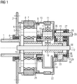
- Fig. 1 represents a wind power transmission with a conventionally designed HSS.
- the wind power transmission comprises a drive-side first planetary stage 1, 5, 7, 8, 16 as an LSS, a second planetary stage 11, 14, 17, 19 20 downstream of the first planetary stage as an IMS and an output-side Spur gear stage 23, 29 as HSS, the gear stages being surrounded by a gear housing 22.
- the drive-side first planetary stage is referred to below as the LSS planetary stage, the output-side second planetary stage as the IMS planetary stage and the output-side spur gear stage as the HSS spur gear stage.
- the two planetary stages each comprise a ring gear 8, 11, a plurality of planet gears 7, 19 mounted in a planet carrier 1, 14 and a sun gear shaft 16, 20.
- the LSS planet gears 7 are rotatable via LSS planet gear bearings 6 on those held in the LSS planet carrier 1 LSS planetary axles 5 mounted.
- the IMS planet gears 19 are rotatably mounted on the IMS planet gear shaft 17 held in the IMS planet carrier 14 via LSS planet gear bearings.
- the two sun gear shafts 16, 20 designed as hollow shafts, i.e. the LSS sun gear shaft 16 and the IMS sun gear shaft 20 surround a pitch tube 12 which runs axially through the gear housing 22 and which forms a channel from the generator-side end to the rotor-side end of the wind power transmission.
- the LSS planet carrier 1 of the drive-side LSS planetary stage has a hollow shaft directed towards the wind rotor for connection to a rotor hub of the wind rotor.
- the LSS planet carrier 1 is rotatably mounted in the gear housing 22 via a drive-side bearing 3, an LSS guide bearing 9 and an output-side bearing 13.
- the drive-side bearing 3 is protected against environmental influences by a rotor-side gear cover 4.
- the LSS guide bearing 9 is arranged on a housing flange 10, which connects the LSS ring gear 8 and the IMS ring gear 11.
- the IMS planet carrier 14 of the IMS planetary stage has a hollow shaft on the drive side, which concentrically surrounds an end section of the LSS sun gear shaft 16 of the LSS planetary stage on the drive side.
- the first clutch 18, which can be designed as a short tooth clutch, between the two planetary stages can be formed by external teeth on the LSS sun gear shaft 16 of the drive-side LSS planetary stage and by internal teeth on the hollow shaft of the IMS planet carrier 14 of the IMS planetary stage his.
- the IMS planet carrier 14, like the LSS planet carrier 1, is rotatably mounted in the gear housing 22 via the bearing 13 on the output side.
- a fastening cover 21 is arranged on the drive-side end of the hollow shaft of the IMS planet carrier 14, which also forms a stop for an inner ring of the drive-side bearing 13.
- the HSS spur gear stage includes an HSS spur gear 23 meshing with it and an HSS hollow shaft 38 which is coaxially surrounded by the HSS spur gear 23 and is connected to it in a rotationally fixed manner.
- the HSS hollow shaft 38 is rotatably supported in a rotor-side bearing 31 and a generator-side bearing 32 in the gear housing 22.
- the generator-side bearing 32 is protected against environmental influences by a generator-side cover 30 of the HSS hollow shaft 38.
- the HSS pinion shaft 29 is rotatably mounted in a rotor-side bearing 26 and a generator-side bearing 27 in the gear housing 22.
- the generator-side bearing 27 is protected against environmental influences by a generator-side cover 28 of the HSS pinion shaft 29.
- the second clutch 15, which can be designed as a short-tooth clutch, between the IMS planetary stage and the HSS spur gear stage is by external teeth on the IMS sun gear shaft 20 of the IMS planetary stage and by internal teeth on the hollow shaft 38 of the HSS spur gear stage educated.
- Fig. 2 represents a wind power transmission with an HSS designed according to the invention. It is like that in Fig. 1 shown wind power transmission around a three-stage gear, the LSS planetary gear stage and the IMS planetary gear stage as in the in Fig. 1 shown wind power transmission are formed. A major difference from that in Fig. 1 The wind power transmission shown is in the HSS: while in the conventionally designed HSS the HSS spur gear 23 is rotatably arranged on a rotatably mounted HSS hollow shaft, in the conventionally designed HSS the HSS spur gear 23 itself is rotatably mounted in the gear housing 22, ie it there is no HSS hollow shaft.
- the HSS spur gear 23 is supported by means of a bearing 24 on a carrier element 25 which is fixedly connected to the gear housing 22.
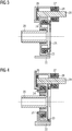
- Fig. 3 is a separate representation of the in Fig. 2 shown HSS. This shows, among other things, that the entire HSS, including the HSS spur gear 23 and the HSS pinion shaft 29, built as an independent module and can be mounted on the gearbox.
- the HSS spur gear 23 is mounted on the generator side in the gear housing 22.
- the support element 25 carrying the bearing 24 projects into a recess on the generator side of the HSS spur gear 23 on the generator side.
- the bearing 24 is arranged between the support element 25 and an inner circumference of a toothed ring of the HSS spur gear 23 that extends radially outward.
- the web between the hub and the ring gear of the HSS spur gear 23 is arranged off-center, so that a space for the bearing arrangement 24 of the HSS spur gear 23 is created between the hub and the ring gear.
- Fig. 4 shows an alternative embodiment of an HSS according to the invention.
- the HSS spur gear 23 is mounted on the rotor side in the gear housing 22.
- the carrier element 25 carrying the bearing 24 protrudes on the rotor side into a rotor-side recess of the HSS spur gear 23.
- the bearing 24 is arranged between the carrier element 25 and a radially further outer circumference of a toothed ring of the HSS spur gear 23.
- Fig. 5 shows an embodiment of an HSS with plain bearings.
- the HSS spur gear 23 is mounted on the generator side in the gear housing 22.
- the carrier element 25 carrying the radial slide bearing 37 projects into a recess on the generator side of the HSS spur gear 23 on the generator side.
- the radial slide bearing 37 is arranged between the support element 25 and an inner circumference of a toothed ring of the HSS spur gear 23 that extends radially further outward.
- a rotor-side end face of the HSS spur gear 23 is supported by means of a rotor-side axial slide bearing 33 on a rotor-side support element which is fixedly connected to the gear housing.
- a generator-side end face of the HSS spur gear 23 is supported by a generator-side axial slide bearing 34 on a generator-side carrier element 25, which is fixedly connected to the gear housing 22.
- Fig. 6 shows an alternative embodiment of an HSS with plain bearings.
- the HSS spur gear 23 is mounted on the generator side in the gear housing 22.
- the carrier element 25 carrying the radial slide bearing 37 protrudes into a recess on the generator side of the HSS spur gear 23 on the generator side.
- the radial slide bearing 37 is arranged between the support element 25 and an outer circumference of the HSS spur gear 23 which extends radially further inwards.
- a rotor-side end face of the HSS spur gear 23 is supported by means of a rotor-side axial slide bearing 33 on a rotor-side support element which is fixedly connected to the gear housing.
- a generator-side end face of the HSS spur gear 23 is supported by means of a generator-side axial slide bearing 34 on a generator-side carrier element 25 which is fixedly connected to the gear housing 22.
- Fig. 7 shows a further embodiment of an HSS with a plain bearing.
- the HSS spur gear 23 is mounted on the generator side in the gear housing 22.
- the carrier element 25 carrying the radial slide bearing 37 protrudes into a recess on the generator side of the HSS spur gear 23 on the generator side.
- the radial slide bearing 37 is arranged between the support element 25 and an outer circumference of the HSS spur gear 23 which extends radially further inwards.
- an end face directed towards the rotor of an axial fastening disk 36 which is fastened axially immovably to the HSS spur gear 23, is supported on the carrier element 25 by means of an axial slide bearing 34 on the generator side.
- an end face of the HSS spur gear 23 facing the generator is supported on the carrier element 25 by means of a rotor-side axial slide bearing 33.
- the carrier element 25 is axially fixed by a cover 35 of the gear housing 22.
- Fig. 8 shows an exploded view of Fig. 7 ,
- the IMS sun gear shaft 20 with external teeth on the generator-side end circumference is arranged in the transmission housing 22.
- the HSS spur gear 23 with an internal toothing on a radially inner circumference is also in the gear housing 22 arranged.
- the sun gear shaft 20 and the HSS spur gear 23 are pushed into one another in such a way that the external toothing of the sun gear shaft 20 meshes with the internal toothing of the HSS spur gear 23.
- a rotor-side axial slide bearing 33, a carrier element 25 with a radial slide bearing 37, a generator-side axial slide bearing 34 and an axial fastening disk 36 are inserted into a generator-side recess in the HSS spur gear 23.
- the generator-side recess of the HSS spur gear 23 is closed with a cover 35.
Claims (6)
- Transmission d'éolienne, comprenant un étage (23, 29) à roue droite tournant rapidement, comportant une roue (23) droite HSS ayant un moyeu et une couronne dentée et un pignon HSS engrenant sur un arbre (29) de pignon HSS, la roue (23) droite HSS étant montée directement dans un carter (22) de la transmission d'éolienne et un arbre (20) de roue solaire d'un étage (11, 19, 20) de transmission, en amont de l'étage (23, 29) de roue droite tournant rapidement, étant couplé directement à la roue (23) droite HSS, dans laquelle
la roue (23) droite HSS a, entre le moyeu et la couronne dentée, une entretoise excentrée et, entre le moyeu et la couronne dentée, est constitué un espace pour un agencement (24) de palier de la roue (23) droite HSS, où l'agencement (24) de palier est disposé radialement entre la couronne dentée et le moyeu,
caractérisée en ce que l'agencement (24) de palier comprend un palier (24), qui est disposé entre un élément (25) de support relié au carter (22) de la transmission et un pourtour intérieur, s'étendant davantage vers l'extérieur radialement, de la roue (23 ) droite HSS. - Transmission d'éolienne, comprenant un étage (23, 29) à roue droite tournant rapidement, comportant une roue (23) droite HSS ayant un moyeu et une couronne dentée et un pignon HSS engrenant sur un arbre (29) de pignon HSS, la roue (23) droite HSS étant montée directement dans un carter (22) de la transmission d'éolienne et un arbre (20) de roue solaire d'un étage (11, 19, 20) de transmission, en amont de l'étage (23, 29) de roue droite tournant rapidement, étant couplé directement à la roue (23) droite HSS, dans laquelle
la roue (23) droite HSS a, entre le moyeu et la couronne dentée, une entretoise excentrée et, entre le moyeu et la couronne dentée, est constitué un espace pour un agencement (24) de palier de la roue (23) droite HSS, où l'agencement (24) de palier est disposé radialement entre la couronne dentée et le moyeu,
caractérisée en ce que l'agencement (24) de palier comprend un palier (24) constitué en palier (37) lisse et qui est disposé entre un élément (25) de support relié au carter (22) de la transmission et un pourtour extérieur, s'étendant davantage vers l'intérieur radialement, de la roue (23) droite HSS. - Transmission d'éolienne suivant la revendication 1 ou 2, dans laquelle l'arbre (29) de pignon HSS forme l'arbre de sortie de la transmission d'éolienne.
- Transmission d'éolienne suivant l'une des revendications 1 à 3, dans laquelle la roue (23) droite HSS est montée d'un seul côté.
- Transmission d'éolienne suivant l'une des revendications précédentes, dans laquelle la roue (23) droite HSS est montée du côté de la roue ou du générateur dans le carter (22) de la transmission.
- Transmission d'éolienne suivant l'une des revendications précédentes, dans laquelle la roue (23) droite HSS est forgée, est soudée ou est vissée en plusieurs éléments ou est fabriquée en une pièce massive au moyen d'un procédé avec enlèvement de copeaux.
Applications Claiming Priority (2)
| Application Number | Priority Date | Filing Date | Title |
|---|---|---|---|
| DE102016214452 | 2016-08-04 | ||
| PCT/EP2017/069498 WO2018024761A1 (fr) | 2016-08-04 | 2017-08-02 | Transmission d'éolienne |
Publications (2)
| Publication Number | Publication Date |
|---|---|
| EP3464894A1 EP3464894A1 (fr) | 2019-04-10 |
| EP3464894B1 true EP3464894B1 (fr) | 2020-02-12 |
Family
ID=59523109
Family Applications (1)
| Application Number | Title | Priority Date | Filing Date |
|---|---|---|---|
| EP17748728.7A Active EP3464894B1 (fr) | 2016-08-04 | 2017-08-02 | Transmission d'éolienne |
Country Status (6)
| Country | Link |
|---|---|
| US (1) | US11078888B2 (fr) |
| EP (1) | EP3464894B1 (fr) |
| CN (1) | CN109563814B (fr) |
| DK (1) | DK3464894T3 (fr) |
| ES (1) | ES2784973T3 (fr) |
| WO (1) | WO2018024761A1 (fr) |
Cited By (1)
| Publication number | Priority date | Publication date | Assignee | Title |
|---|---|---|---|---|
| US20230250871A1 (en) * | 2020-07-31 | 2023-08-10 | Zf Friedrichshafen Ag | Integrated design of a sun shaft |
Citations (3)
| Publication number | Priority date | Publication date | Assignee | Title |
|---|---|---|---|---|
| US20080202269A1 (en) | 2007-02-23 | 2008-08-28 | Jtekt Corporation | Strain wave reduction gear and variable transmission ratio steering apparatus |
| CN201358892Y (zh) | 2009-03-09 | 2009-12-09 | 大连华锐股份有限公司 | 风力发电增速齿轮箱 |
| DE102009059671A1 (de) | 2009-12-19 | 2011-06-22 | Robert Bosch GmbH, 70469 | Generatoranordnung für eine Windenergieanlage |
Family Cites Families (26)
| Publication number | Priority date | Publication date | Assignee | Title |
|---|---|---|---|---|
| US2320379A (en) * | 1940-06-01 | 1943-06-01 | Master Electric Co | Electric motor gearing |
| US2547079A (en) * | 1947-05-05 | 1951-04-03 | Const Electro Mecaniques De Sa | Transmission for drilling machines |
| US3242754A (en) * | 1963-09-16 | 1966-03-29 | Safety Electrical Equipment Co | Transmission |
| YU158381A (en) * | 1980-06-28 | 1983-09-30 | Voith Gmbh J M | Press roller with adjustable bending |
| DE102006038396A1 (de) * | 2006-08-15 | 2008-02-21 | Kordel Antriebstechnik Gmbh | Frontachsgetriebe |
| DE102007025755A1 (de) * | 2007-06-01 | 2008-12-04 | Karl Hehl | Getriebeeinheit für eine Spritzgießeinheit |
| GB0719119D0 (en) * | 2007-10-01 | 2007-11-07 | Orbital 2 Ltd | A transmission system for power generation |
| DK2284420T3 (da) * | 2009-08-10 | 2012-07-30 | Zf Wind Power Antwerpen Nv | Parallelgear til en gearkasse til en vindturbine |
| GB2473875A (en) * | 2009-09-28 | 2011-03-30 | Hansen Transmissions Int | Wind turbine gearbox with planetary gear unit having sliding bearings |
| WO2011070984A1 (fr) * | 2009-12-07 | 2011-06-16 | 三菱重工業株式会社 | Structure d'étanchéité d'un dispositif mécanique et générateur à énergie éolienne |
| EP2385611B1 (fr) * | 2010-05-06 | 2013-02-13 | Moventas Gears Oy | Dispositif électromécanique |
| KR20110128062A (ko) * | 2010-05-20 | 2011-11-28 | 두산모트롤주식회사 | 풍력발전기의 증속기 |
| KR20110128054A (ko) | 2010-05-20 | 2011-11-28 | 두산모트롤주식회사 | 풍력발전기의 증속기 |
| CN102575750A (zh) * | 2010-08-31 | 2012-07-11 | 三菱重工业株式会社 | 行星齿轮机构、轴承结构、风力发电装置及行星齿轮的制造方法 |
| DE102010060147B4 (de) * | 2010-10-25 | 2017-03-09 | Eickhoff Antriebstechnik Gmbh | Planetengetriebe mit einem Zentralverteiler |
| ITBO20100109U1 (it) * | 2010-10-29 | 2012-04-30 | Bonfiglioli Riduttori Spa | Riduttore epicicloidale |
| CN102312928A (zh) * | 2011-08-24 | 2012-01-11 | 重庆齿轮箱有限责任公司 | 花键润滑结构 |
| US8338980B2 (en) * | 2011-10-25 | 2012-12-25 | General Electric Company | Wind turbine with single-stage compact drive train |
| ES2472698T3 (es) * | 2011-11-17 | 2014-07-02 | Siemens Aktiengesellschaft | Engranaje para una instalación de energía e�lica |
| CN203230542U (zh) * | 2012-12-15 | 2013-10-09 | 大连华锐重工集团股份有限公司 | 一种大功率高速风力发电机用主传动增速齿轮箱 |
| AT513743B1 (de) * | 2013-01-30 | 2014-07-15 | Miba Gleitlager Gmbh | Windkraftanlagengetriebe |
| DE102013217950A1 (de) | 2013-09-09 | 2015-03-12 | Siemens Aktiengesellschaft | Planetengetriebe für eine Windkraftanlage |
| CN104061316B (zh) * | 2014-06-30 | 2016-09-14 | 南车戚墅堰机车车辆工艺研究所有限公司 | 风电齿轮箱的低速轴支撑结构 |
| CN104564544B (zh) * | 2015-01-05 | 2017-05-24 | 浙江大学 | 一种风电机组的直接增速式连续变速型传动链结构 |
| JP6794211B2 (ja) * | 2016-10-14 | 2020-12-02 | Ntn株式会社 | インホイールモータ駆動装置 |
| JP6125083B1 (ja) * | 2016-10-17 | 2017-05-10 | Ntn株式会社 | インホイールモータ駆動装置 |
-
2017
- 2017-08-02 US US16/322,839 patent/US11078888B2/en active Active
- 2017-08-02 CN CN201780047859.XA patent/CN109563814B/zh active Active
- 2017-08-02 ES ES17748728T patent/ES2784973T3/es active Active
- 2017-08-02 WO PCT/EP2017/069498 patent/WO2018024761A1/fr active Search and Examination
- 2017-08-02 EP EP17748728.7A patent/EP3464894B1/fr active Active
- 2017-08-02 DK DK17748728.7T patent/DK3464894T3/da active
Patent Citations (3)
| Publication number | Priority date | Publication date | Assignee | Title |
|---|---|---|---|---|
| US20080202269A1 (en) | 2007-02-23 | 2008-08-28 | Jtekt Corporation | Strain wave reduction gear and variable transmission ratio steering apparatus |
| CN201358892Y (zh) | 2009-03-09 | 2009-12-09 | 大连华锐股份有限公司 | 风力发电增速齿轮箱 |
| DE102009059671A1 (de) | 2009-12-19 | 2011-06-22 | Robert Bosch GmbH, 70469 | Generatoranordnung für eine Windenergieanlage |
Non-Patent Citations (1)
| Title |
|---|
| UTE DRESCHER: "Gleitlager als Alternative zu Wälzlager in Windgetrieben", KONSTRUKTIONSPRAXIS, 10 November 2011 (2011-11-10), XP055745826, Retrieved from the Internet <URL:https://www.konstruktionspraxis.vogel.de/gleitlager-als-alternative-zu-waelzlager-in-windgetrieben-a-338401> |
Cited By (2)
| Publication number | Priority date | Publication date | Assignee | Title |
|---|---|---|---|---|
| US20230250871A1 (en) * | 2020-07-31 | 2023-08-10 | Zf Friedrichshafen Ag | Integrated design of a sun shaft |
| US11913538B2 (en) * | 2020-07-31 | 2024-02-27 | Zf Friedrichshafen Ag | Integrated design of a sun shaft |
Also Published As
| Publication number | Publication date |
|---|---|
| DK3464894T3 (da) | 2020-04-27 |
| WO2018024761A1 (fr) | 2018-02-08 |
| US20190186469A1 (en) | 2019-06-20 |
| EP3464894A1 (fr) | 2019-04-10 |
| CN109563814A (zh) | 2019-04-02 |
| US11078888B2 (en) | 2021-08-03 |
| CN109563814B (zh) | 2020-06-23 |
| ES2784973T3 (es) | 2020-10-02 |
Similar Documents
| Publication | Publication Date | Title |
|---|---|---|
| EP2951434B1 (fr) | Transmission d'éolienne | |
| DE10217343B4 (de) | Reduktionsgetriebe | |
| EP3001071B1 (fr) | Barre planétaire - alésage d'huile | |
| EP2565495B1 (fr) | Drive device with support bolts for a vehicle | |
| EP2594789A1 (fr) | Engrenage pour une éolienne | |
| EP3129681B1 (fr) | Palier à glissement pour support épicycloïdal | |
| EP3322908B1 (fr) | Mécanisme de transmission comprenant un flasque de butée pour le blocage axial d'éléments roulants d'un palier | |
| DE102016118877B4 (de) | Mechanische Getriebeanordnung | |
| EP3001020A1 (fr) | Groupe motopropulseur dote d'un dispositif de compresseur | |
| EP3351826B1 (fr) | Boîte de transmission multi-étagée compacte comprenant un engrenage planétaire et une démultiplication harmonique s'y raccordant | |
| DE10159973A1 (de) | Getriebe für eine Windkraftanlage | |
| EP2295831B1 (fr) | Différentiel | |
| DE102008024049B4 (de) | Lageranordnung mit einer Vorspanneinrichtung | |
| WO2020118328A1 (fr) | Train planétaire destiné à une éolienne | |
| DE102015205264A1 (de) | Antriebseinheit für ein Flurförderzeug und Flurförderzeug | |
| WO2017016552A1 (fr) | Système de transmission pour véhicule automobile | |
| EP3464894B1 (fr) | Transmission d'éolienne | |
| DE102019121079B3 (de) | Kompakte Getriebeanordnung mit Stufenplanetensatz und Stirnraddifferential | |
| EP0622544B1 (fr) | Dispositif de réglage des pales de pompe à écoulement axial | |
| WO2014044277A1 (fr) | Système de transmission | |
| DE10250439A1 (de) | Leistungsverzweigtes Winkelgetriebe | |
| DE102012014273A1 (de) | Getriebe mit Leistungsverzweigung | |
| DE202006011877U1 (de) | Untersetzungsgetriebe | |
| AT505628B1 (de) | Getriebe zur umkehrspielfreien kraftübertragung | |
| DE102018127721B4 (de) | Getriebevorrichtung für ein Kraftfahrzeug |
Legal Events
| Date | Code | Title | Description |
|---|---|---|---|
| STAA | Information on the status of an ep patent application or granted ep patent |
Free format text: STATUS: UNKNOWN |
|
| STAA | Information on the status of an ep patent application or granted ep patent |
Free format text: STATUS: THE INTERNATIONAL PUBLICATION HAS BEEN MADE |
|
| PUAI | Public reference made under article 153(3) epc to a published international application that has entered the european phase |
Free format text: ORIGINAL CODE: 0009012 |
|
| STAA | Information on the status of an ep patent application or granted ep patent |
Free format text: STATUS: REQUEST FOR EXAMINATION WAS MADE |
|
| 17P | Request for examination filed |
Effective date: 20190102 |
|
| AK | Designated contracting states |
Kind code of ref document: A1 Designated state(s): AL AT BE BG CH CY CZ DE DK EE ES FI FR GB GR HR HU IE IS IT LI LT LU LV MC MK MT NL NO PL PT RO RS SE SI SK SM TR |
|
| AX | Request for extension of the european patent |
Extension state: BA ME |
|
| GRAP | Despatch of communication of intention to grant a patent |
Free format text: ORIGINAL CODE: EPIDOSNIGR1 |
|
| STAA | Information on the status of an ep patent application or granted ep patent |
Free format text: STATUS: GRANT OF PATENT IS INTENDED |
|
| RIC1 | Information provided on ipc code assigned before grant |
Ipc: F03D 80/70 20160101ALI20191003BHEP Ipc: F16H 1/46 20060101ALI20191003BHEP Ipc: F03D 15/00 20160101AFI20191003BHEP |
|
| DAV | Request for validation of the european patent (deleted) | ||
| DAX | Request for extension of the european patent (deleted) | ||
| INTG | Intention to grant announced |
Effective date: 20191016 |
|
| GRAS | Grant fee paid |
Free format text: ORIGINAL CODE: EPIDOSNIGR3 |
|
| GRAA | (expected) grant |
Free format text: ORIGINAL CODE: 0009210 |
|
| STAA | Information on the status of an ep patent application or granted ep patent |
Free format text: STATUS: THE PATENT HAS BEEN GRANTED |
|
| AK | Designated contracting states |
Kind code of ref document: B1 Designated state(s): AL AT BE BG CH CY CZ DE DK EE ES FI FR GB GR HR HU IE IS IT LI LT LU LV MC MK MT NL NO PL PT RO RS SE SI SK SM TR |
|
| REG | Reference to a national code |
Ref country code: GB Ref legal event code: FG4D Free format text: NOT ENGLISH |
|
| REG | Reference to a national code |
Ref country code: CH Ref legal event code: EP |
|
| REG | Reference to a national code |
Ref country code: AT Ref legal event code: REF Ref document number: 1232440 Country of ref document: AT Kind code of ref document: T Effective date: 20200215 |
|
| REG | Reference to a national code |
Ref country code: IE Ref legal event code: FG4D Free format text: LANGUAGE OF EP DOCUMENT: GERMAN |
|
| REG | Reference to a national code |
Ref country code: DE Ref legal event code: R096 Ref document number: 502017003808 Country of ref document: DE |
|
| REG | Reference to a national code |
Ref country code: DK Ref legal event code: T3 Effective date: 20200423 |
|
| REG | Reference to a national code |
Ref country code: SE Ref legal event code: TRGR |
|
| PG25 | Lapsed in a contracting state [announced via postgrant information from national office to epo] |
Ref country code: RS Free format text: LAPSE BECAUSE OF FAILURE TO SUBMIT A TRANSLATION OF THE DESCRIPTION OR TO PAY THE FEE WITHIN THE PRESCRIBED TIME-LIMIT Effective date: 20200212 Ref country code: NO Free format text: LAPSE BECAUSE OF FAILURE TO SUBMIT A TRANSLATION OF THE DESCRIPTION OR TO PAY THE FEE WITHIN THE PRESCRIBED TIME-LIMIT Effective date: 20200512 Ref country code: FI Free format text: LAPSE BECAUSE OF FAILURE TO SUBMIT A TRANSLATION OF THE DESCRIPTION OR TO PAY THE FEE WITHIN THE PRESCRIBED TIME-LIMIT Effective date: 20200212 |
|
| REG | Reference to a national code |
Ref country code: LT Ref legal event code: MG4D |
|
| REG | Reference to a national code |
Ref country code: NL Ref legal event code: MP Effective date: 20200212 |
|
| PG25 | Lapsed in a contracting state [announced via postgrant information from national office to epo] |
Ref country code: HR Free format text: LAPSE BECAUSE OF FAILURE TO SUBMIT A TRANSLATION OF THE DESCRIPTION OR TO PAY THE FEE WITHIN THE PRESCRIBED TIME-LIMIT Effective date: 20200212 Ref country code: LV Free format text: LAPSE BECAUSE OF FAILURE TO SUBMIT A TRANSLATION OF THE DESCRIPTION OR TO PAY THE FEE WITHIN THE PRESCRIBED TIME-LIMIT Effective date: 20200212 Ref country code: BG Free format text: LAPSE BECAUSE OF FAILURE TO SUBMIT A TRANSLATION OF THE DESCRIPTION OR TO PAY THE FEE WITHIN THE PRESCRIBED TIME-LIMIT Effective date: 20200512 Ref country code: IS Free format text: LAPSE BECAUSE OF FAILURE TO SUBMIT A TRANSLATION OF THE DESCRIPTION OR TO PAY THE FEE WITHIN THE PRESCRIBED TIME-LIMIT Effective date: 20200612 Ref country code: GR Free format text: LAPSE BECAUSE OF FAILURE TO SUBMIT A TRANSLATION OF THE DESCRIPTION OR TO PAY THE FEE WITHIN THE PRESCRIBED TIME-LIMIT Effective date: 20200513 |
|
| PG25 | Lapsed in a contracting state [announced via postgrant information from national office to epo] |
Ref country code: NL Free format text: LAPSE BECAUSE OF FAILURE TO SUBMIT A TRANSLATION OF THE DESCRIPTION OR TO PAY THE FEE WITHIN THE PRESCRIBED TIME-LIMIT Effective date: 20200212 |
|
| REG | Reference to a national code |
Ref country code: ES Ref legal event code: FG2A Ref document number: 2784973 Country of ref document: ES Kind code of ref document: T3 Effective date: 20201002 |
|
| REG | Reference to a national code |
Ref country code: DE Ref legal event code: R026 Ref document number: 502017003808 Country of ref document: DE |
|
| PLBI | Opposition filed |
Free format text: ORIGINAL CODE: 0009260 |
|
| PG25 | Lapsed in a contracting state [announced via postgrant information from national office to epo] |
Ref country code: RO Free format text: LAPSE BECAUSE OF FAILURE TO SUBMIT A TRANSLATION OF THE DESCRIPTION OR TO PAY THE FEE WITHIN THE PRESCRIBED TIME-LIMIT Effective date: 20200212 Ref country code: SK Free format text: LAPSE BECAUSE OF FAILURE TO SUBMIT A TRANSLATION OF THE DESCRIPTION OR TO PAY THE FEE WITHIN THE PRESCRIBED TIME-LIMIT Effective date: 20200212 Ref country code: PT Free format text: LAPSE BECAUSE OF FAILURE TO SUBMIT A TRANSLATION OF THE DESCRIPTION OR TO PAY THE FEE WITHIN THE PRESCRIBED TIME-LIMIT Effective date: 20200705 Ref country code: EE Free format text: LAPSE BECAUSE OF FAILURE TO SUBMIT A TRANSLATION OF THE DESCRIPTION OR TO PAY THE FEE WITHIN THE PRESCRIBED TIME-LIMIT Effective date: 20200212 Ref country code: SM Free format text: LAPSE BECAUSE OF FAILURE TO SUBMIT A TRANSLATION OF THE DESCRIPTION OR TO PAY THE FEE WITHIN THE PRESCRIBED TIME-LIMIT Effective date: 20200212 Ref country code: LT Free format text: LAPSE BECAUSE OF FAILURE TO SUBMIT A TRANSLATION OF THE DESCRIPTION OR TO PAY THE FEE WITHIN THE PRESCRIBED TIME-LIMIT Effective date: 20200212 Ref country code: CZ Free format text: LAPSE BECAUSE OF FAILURE TO SUBMIT A TRANSLATION OF THE DESCRIPTION OR TO PAY THE FEE WITHIN THE PRESCRIBED TIME-LIMIT Effective date: 20200212 |
|
| 26 | Opposition filed |
Opponent name: ZF FRIEDRICHSHAFEN AG Effective date: 20201021 |
|
| PLAX | Notice of opposition and request to file observation + time limit sent |
Free format text: ORIGINAL CODE: EPIDOSNOBS2 |
|
| PG25 | Lapsed in a contracting state [announced via postgrant information from national office to epo] |
Ref country code: PL Free format text: LAPSE BECAUSE OF FAILURE TO SUBMIT A TRANSLATION OF THE DESCRIPTION OR TO PAY THE FEE WITHIN THE PRESCRIBED TIME-LIMIT Effective date: 20200212 Ref country code: SI Free format text: LAPSE BECAUSE OF FAILURE TO SUBMIT A TRANSLATION OF THE DESCRIPTION OR TO PAY THE FEE WITHIN THE PRESCRIBED TIME-LIMIT Effective date: 20200212 |
|
| PLBB | Reply of patent proprietor to notice(s) of opposition received |
Free format text: ORIGINAL CODE: EPIDOSNOBS3 |
|
| REG | Reference to a national code |
Ref country code: CH Ref legal event code: NV Representative=s name: SIEMENS SCHWEIZ AG, CH |
|
| PLAB | Opposition data, opponent's data or that of the opponent's representative modified |
Free format text: ORIGINAL CODE: 0009299OPPO |
|
| PG25 | Lapsed in a contracting state [announced via postgrant information from national office to epo] |
Ref country code: MC Free format text: LAPSE BECAUSE OF FAILURE TO SUBMIT A TRANSLATION OF THE DESCRIPTION OR TO PAY THE FEE WITHIN THE PRESCRIBED TIME-LIMIT Effective date: 20200212 |
|
| REG | Reference to a national code |
Ref country code: CH Ref legal event code: PL |
|
| R26 | Opposition filed (corrected) |
Opponent name: ZF FRIEDRICHSHAFEN AG Effective date: 20201021 |
|
| PG25 | Lapsed in a contracting state [announced via postgrant information from national office to epo] |
Ref country code: LI Free format text: LAPSE BECAUSE OF NON-PAYMENT OF DUE FEES Effective date: 20200831 Ref country code: LU Free format text: LAPSE BECAUSE OF NON-PAYMENT OF DUE FEES Effective date: 20200802 Ref country code: CH Free format text: LAPSE BECAUSE OF NON-PAYMENT OF DUE FEES Effective date: 20200831 |
|
| REG | Reference to a national code |
Ref country code: DE Ref legal event code: R082 Ref document number: 502017003808 Country of ref document: DE Representative=s name: MICHALSKI HUETTERMANN & PARTNER PATENTANWAELTE, DE |
|
| REG | Reference to a national code |
Ref country code: BE Ref legal event code: MM Effective date: 20200831 |
|
| PLCK | Communication despatched that opposition was rejected |
Free format text: ORIGINAL CODE: EPIDOSNREJ1 |
|
| APAH | Appeal reference modified |
Free format text: ORIGINAL CODE: EPIDOSCREFNO |
|
| APBM | Appeal reference recorded |
Free format text: ORIGINAL CODE: EPIDOSNREFNO |
|
| APBP | Date of receipt of notice of appeal recorded |
Free format text: ORIGINAL CODE: EPIDOSNNOA2O |
|
| PG25 | Lapsed in a contracting state [announced via postgrant information from national office to epo] |
Ref country code: IE Free format text: LAPSE BECAUSE OF NON-PAYMENT OF DUE FEES Effective date: 20200802 Ref country code: BE Free format text: LAPSE BECAUSE OF NON-PAYMENT OF DUE FEES Effective date: 20200831 |
|
| APBQ | Date of receipt of statement of grounds of appeal recorded |
Free format text: ORIGINAL CODE: EPIDOSNNOA3O |
|
| PG25 | Lapsed in a contracting state [announced via postgrant information from national office to epo] |
Ref country code: TR Free format text: LAPSE BECAUSE OF FAILURE TO SUBMIT A TRANSLATION OF THE DESCRIPTION OR TO PAY THE FEE WITHIN THE PRESCRIBED TIME-LIMIT Effective date: 20200212 Ref country code: MT Free format text: LAPSE BECAUSE OF FAILURE TO SUBMIT A TRANSLATION OF THE DESCRIPTION OR TO PAY THE FEE WITHIN THE PRESCRIBED TIME-LIMIT Effective date: 20200212 Ref country code: CY Free format text: LAPSE BECAUSE OF FAILURE TO SUBMIT A TRANSLATION OF THE DESCRIPTION OR TO PAY THE FEE WITHIN THE PRESCRIBED TIME-LIMIT Effective date: 20200212 |
|
| PG25 | Lapsed in a contracting state [announced via postgrant information from national office to epo] |
Ref country code: MK Free format text: LAPSE BECAUSE OF FAILURE TO SUBMIT A TRANSLATION OF THE DESCRIPTION OR TO PAY THE FEE WITHIN THE PRESCRIBED TIME-LIMIT Effective date: 20200212 Ref country code: AL Free format text: LAPSE BECAUSE OF FAILURE TO SUBMIT A TRANSLATION OF THE DESCRIPTION OR TO PAY THE FEE WITHIN THE PRESCRIBED TIME-LIMIT Effective date: 20200212 |
|
| REG | Reference to a national code |
Ref country code: DE Ref legal event code: R100 Ref document number: 502017003808 Country of ref document: DE |
|
| APBU | Appeal procedure closed |
Free format text: ORIGINAL CODE: EPIDOSNNOA9O |
|
| PLBN | Opposition rejected |
Free format text: ORIGINAL CODE: 0009273 |
|
| STAA | Information on the status of an ep patent application or granted ep patent |
Free format text: STATUS: OPPOSITION REJECTED |
|
| 27O | Opposition rejected |
Effective date: 20230127 |
|
| REG | Reference to a national code |
Ref country code: AT Ref legal event code: MM01 Ref document number: 1232440 Country of ref document: AT Kind code of ref document: T Effective date: 20220802 |
|
| PG25 | Lapsed in a contracting state [announced via postgrant information from national office to epo] |
Ref country code: AT Free format text: LAPSE BECAUSE OF NON-PAYMENT OF DUE FEES Effective date: 20220802 |
|
| PGFP | Annual fee paid to national office [announced via postgrant information from national office to epo] |
Ref country code: IT Payment date: 20230825 Year of fee payment: 7 Ref country code: GB Payment date: 20230822 Year of fee payment: 7 |
|
| PGFP | Annual fee paid to national office [announced via postgrant information from national office to epo] |
Ref country code: SE Payment date: 20230821 Year of fee payment: 7 Ref country code: FR Payment date: 20230828 Year of fee payment: 7 Ref country code: DK Payment date: 20230823 Year of fee payment: 7 Ref country code: DE Payment date: 20230830 Year of fee payment: 7 |
|
| PGFP | Annual fee paid to national office [announced via postgrant information from national office to epo] |
Ref country code: ES Payment date: 20231027 Year of fee payment: 7 |