EP3464080B1 - Dispositif et procede d'empaquetage d'element de calage dans un carton - Google Patents
Dispositif et procede d'empaquetage d'element de calage dans un carton Download PDFInfo
- Publication number
- EP3464080B1 EP3464080B1 EP17732972.9A EP17732972A EP3464080B1 EP 3464080 B1 EP3464080 B1 EP 3464080B1 EP 17732972 A EP17732972 A EP 17732972A EP 3464080 B1 EP3464080 B1 EP 3464080B1
- Authority
- EP
- European Patent Office
- Prior art keywords
- along
- carton
- packing device
- cassette
- cushioning element
- Prior art date
- Legal status (The legal status is an assumption and is not a legal conclusion. Google has not performed a legal analysis and makes no representation as to the accuracy of the status listed.)
- Active
Links
Images


Classifications
-
- B—PERFORMING OPERATIONS; TRANSPORTING
- B65—CONVEYING; PACKING; STORING; HANDLING THIN OR FILAMENTARY MATERIAL
- B65B—MACHINES, APPARATUS OR DEVICES FOR, OR METHODS OF, PACKAGING ARTICLES OR MATERIALS; UNPACKING
- B65B55/00—Preserving, protecting or purifying packages or package contents in association with packaging
- B65B55/20—Embedding contents in shock-absorbing media, e.g. plastic foam, granular material
-
- B—PERFORMING OPERATIONS; TRANSPORTING
- B65—CONVEYING; PACKING; STORING; HANDLING THIN OR FILAMENTARY MATERIAL
- B65B—MACHINES, APPARATUS OR DEVICES FOR, OR METHODS OF, PACKAGING ARTICLES OR MATERIALS; UNPACKING
- B65B63/00—Auxiliary devices, not otherwise provided for, for operating on articles or materials to be packaged
- B65B63/02—Auxiliary devices, not otherwise provided for, for operating on articles or materials to be packaged for compressing or compacting articles or materials prior to wrapping or insertion in containers or receptacles
-
- B—PERFORMING OPERATIONS; TRANSPORTING
- B25—HAND TOOLS; PORTABLE POWER-DRIVEN TOOLS; MANIPULATORS
- B25J—MANIPULATORS; CHAMBERS PROVIDED WITH MANIPULATION DEVICES
- B25J15/00—Gripping heads and other end effectors
- B25J15/0052—Gripping heads and other end effectors multiple gripper units or multiple end effectors
-
- B—PERFORMING OPERATIONS; TRANSPORTING
- B25—HAND TOOLS; PORTABLE POWER-DRIVEN TOOLS; MANIPULATORS
- B25J—MANIPULATORS; CHAMBERS PROVIDED WITH MANIPULATION DEVICES
- B25J15/00—Gripping heads and other end effectors
- B25J15/02—Gripping heads and other end effectors servo-actuated
- B25J15/0253—Gripping heads and other end effectors servo-actuated comprising parallel grippers
-
- B—PERFORMING OPERATIONS; TRANSPORTING
- B25—HAND TOOLS; PORTABLE POWER-DRIVEN TOOLS; MANIPULATORS
- B25J—MANIPULATORS; CHAMBERS PROVIDED WITH MANIPULATION DEVICES
- B25J9/00—Programme-controlled manipulators
- B25J9/0093—Programme-controlled manipulators co-operating with conveyor means
-
- B—PERFORMING OPERATIONS; TRANSPORTING
- B25—HAND TOOLS; PORTABLE POWER-DRIVEN TOOLS; MANIPULATORS
- B25J—MANIPULATORS; CHAMBERS PROVIDED WITH MANIPULATION DEVICES
- B25J9/00—Programme-controlled manipulators
- B25J9/02—Programme-controlled manipulators characterised by movement of the arms, e.g. cartesian coordinate type
- B25J9/023—Cartesian coordinate type
-
- B—PERFORMING OPERATIONS; TRANSPORTING
- B65—CONVEYING; PACKING; STORING; HANDLING THIN OR FILAMENTARY MATERIAL
- B65B—MACHINES, APPARATUS OR DEVICES FOR, OR METHODS OF, PACKAGING ARTICLES OR MATERIALS; UNPACKING
- B65B35/00—Supplying, feeding, arranging or orientating articles to be packaged
- B65B35/10—Feeding, e.g. conveying, single articles
- B65B35/16—Feeding, e.g. conveying, single articles by grippers
-
- B—PERFORMING OPERATIONS; TRANSPORTING
- B65—CONVEYING; PACKING; STORING; HANDLING THIN OR FILAMENTARY MATERIAL
- B65B—MACHINES, APPARATUS OR DEVICES FOR, OR METHODS OF, PACKAGING ARTICLES OR MATERIALS; UNPACKING
- B65B43/00—Forming, feeding, opening or setting-up containers or receptacles in association with packaging
- B65B43/42—Feeding or positioning bags, boxes, or cartons in the distended, opened, or set-up state; Feeding preformed rigid containers, e.g. tins, capsules, glass tubes, glasses, to the packaging position; Locating containers or receptacles at the filling position; Supporting containers or receptacles during the filling operation
- B65B43/52—Feeding or positioning bags, boxes, or cartons in the distended, opened, or set-up state; Feeding preformed rigid containers, e.g. tins, capsules, glass tubes, glasses, to the packaging position; Locating containers or receptacles at the filling position; Supporting containers or receptacles during the filling operation using roller-ways or endless conveyors
Definitions
- the present invention relates to an automated packaging device for a dunnage element in a carton, as well as its methods of implementation.
- EP 2 370 319 discloses the placement, by a custom produced plastic bag gripping arm, according to the distribution of the empty space geometry of a carton. This system precisely positions the wedging elements around the articles, but does not ensure placement under stress of the wedging elements, ensuring that the articles are held in position in a compressed manner in a box.
- EP 1 410 995 A1 discloses an insert placement device in a carton and serves as the basis for the preamble of claim 1.
- the present invention thus provides a device and methods for automated packaging of a wedging element in a cardboard box, making it possible to overcome the aforementioned drawbacks.
- the device for automatic packaging of wedging element (s) in a carton is intended to be mounted along a conveyor directed along a longitudinal axis.
- the packaging device comprises a robotic cell associated with a dunnage element storage area, the robotic cell comprising at least one dunnage element gripping means, while the storage area is at least one magazine comprising at least one dunnage element. at least one cassette movable along a transverse axis from a loading position to an unloading position.
- robotic cell is contiguous along the transverse axis to at least one store.
- a cassette in the unloading position, a cassette is located below at least one wedging element gripping means.
- the robotic cell comprises a frame made up of uprights, while the conveyor is intended to pass right through the uprights.
- At least one cassette is removable.
- At least one cassette is associated with at least one wedging element distributor directed along a longitudinal axis.
- At least one gripping means is movable along a vertical axis.
- At least one gripping means comprises a clamp comprising two jaws movable along a longitudinal axis.
- At least one gripping means is associated with a vertical release means of a wedging element.
- At least one gripping means is carried by two plates movable along vertical axes.
- the method comprises a step of acquisition by an automaton of the length, the width and the height of a supported box, while it comprises a step of determining the number and the type. of wedging element to be inserted into the supported box.
- the packaging device (1) of the wedging element (2) is presented by a robotic cell (3) associated with at least one zone of wedging element storage, which is presented by at least one magazine (18) equipped with mobile cassette (s) (8).
- a robotic cell (3) according to the invention comprises at least one means for placing the cardboard (C) at a reference zero point, advantageously at least one means for detecting the coordinates of the ends of the flaps, advantageously at least one means for partial opening of at least one flap, at least one gripping means.
- cardboard (C) is used interchangeably in this description to denote a receptacle, a box or a container in which is packaged at least one article and at least one wedging element (2).
- zero point is understood to mean the reference point advantageously represented by the center of the frame of the robotic cell (3), directly above the conveyor (4). It is understood that a zero point can be anywhere, depending on the configuration of the robotic cell (3).
- the position of the reference zero point may change according to the number of wedging elements (2) to be introduced, namely according to the even or odd number, as explained in more detail in the remainder of the description.
- the packaging device (1) comprises a robotic cell (3), intended to be associated with a conveyor (4) with belt or rollers, preferably with rollers, which conveys the boxes (C) according to a longitudinal axis (Y, Y '), at least one wedging element storage area and advantageously at least one wedging element distributor (2).
- wedging element dispenser (2) is understood to mean a device which dispenses an advantageously compressible element.
- the dispenser shapes, from a folded paper strip, a wedging element (2), as explained in more detail in the remainder of the description.
- the packaging device (1) advantageously comprises a presence sensor, for detecting the arrival of a box (C) at the robotic cell (3).
- This presence sensor in particular operates the zero setting means, as explained in more detail in the remainder of the description.
- each of the mobile elements is moved by a motorized device, such as commonly used in the field of mechatronics, for example by pistons, slides, rails, chains, linear motors and / or belts.
- a motorized device such as commonly used in the field of mechatronics, for example by pistons, slides, rails, chains, linear motors and / or belts.
- the packaging device (1) for the wedging element (2) comprises at least one means for determining the dimensions of a carton (C) prior to its being taken over by the robotic cell (3).
- a means for determining the dimensions of a carton can be reading bar codes, determining the empty space or determining the length, width and height of a carton, by means of appropriate probes.
- Article packaging in a carton is commonly done manually or accomplished semi-automatically.
- the articles to be packaged are advantageously placed, manually or in an automated manner, in cartons upstream of the taking over by the packaging device (1).
- a packaging line along a conveyor (4) or a succession of independent stations, comprises first of all an erector, shaping the folded boxes, and finally advantageously a sealer or also called a scotcheuse, closing the flaps of the boxes mechanically and sealing them with an adhesive.
- an appropriate device positions a cover on the latter at the outlet of the packaging device (1) according to the invention.
- a carton (C) is composed in a common way, of two pairs of opposite flaps, namely two so-called short flaps (RC) and two so-called long flaps (RL), connected to the corresponding side walls of the carton (C).
- a box does not include flaps, and therefore consists of side walls, namely two so-called long walls and two so-called short walls, and a bottom wall.
- the flaps are in a neutral position, namely, in the extension of the side walls, perpendicular to the bottom wall, in a vertical manner.
- a cardboard orienter also called an orientation changer, allowing the boxes to be rotated and aligned in a desired direction, is advantageously placed upstream of the packaging device (1) according to the invention.
- a box generally has a rectangular section, made up of long sides and small sides, namely so-called long side walls and said short side walls respectively.
- a box is conveyed in the direction of the packaging device (1), preferably in the length direction, namely that the long sides are directed along the longitudinal axis (Y, Y '), while the short sides are directed along a transverse axis (X, X ').
- the boxes are oriented in the direction of the length in order to reduce the number of wedging element to be introduced, thus it is the long flaps (RL) which are partially open, while the short flaps (RC) are left in their neutral arrival position, see maintained in a vertical position by appropriate means, as explained in more detail in the remainder of the description.
- the cartons could be oriented in the direction of the width, however a greater number of wedging elements would be necessary to wedge the articles in a carton, which would imply a longer handling time, therefore a lower rate, and necessarily, for large boxes, the width of the conveyor should be greater. It is therefore understood that this configuration is not preferred.
- a wedging element (2) is a compressible element having elastic properties.
- the wedging elements (2) are advantageously hollow profiles, such as tubes of crumpled paper, formed of a strip of paper folded back on itself, namely, assembled on its lateral edges and glued.
- This strip of paper is crumpled both in a longitudinal direction and in a radial direction, by a suitable dispenser, such as that described by the document.
- a suitable dispenser such as that described by the document.
- EP 1,539,474 .
- This strip of paper is cut according to a length determined preferably according to the length or the width of a cardboard, namely preferably a length greater than the length of a cardboard (C), in which at least one wedging element (2 ), thus produced, is positioned in a compressed manner.
- the wedging elements (2) can also be of different material, shape and structure.
- the wedging elements (2) are preferably of tubular shape, but it could be otherwise, such as triangular, square or rectangular.
- These compressible elements are first of all compressible at least longitudinally by a gripping means, in order to be inserted into a cardboard, preferably placed parallel to the long flaps (RL) of a cardboard box, but it could be otherwise, these compressible elements are placed parallel to the side walls, preferably the so-called long walls.
- At least one wedging element (2) is positioned at least at the level of a pair of flaps, preferably the short flaps (RC).
- At least one wedging element (2) is positioned in compression at the level of the so-called short side walls.
- the lower end, of at least one wedging element (2) is positioned at the upper ends of the side walls of the carton.
- wedging element (2) is meant a material, shape or appropriate length of a wedging element (2), to be distributed according to the dimensioning of the cardboard and in particular according to its positioning, namely at the bottom of the box. carton or on the surface thereof.
- These compressible elements are also radially compressible during their positioning in a cardboard box, in particular one beside the other, preferably in the width direction and vertically during the closing of the flaps or the positioning of a cover, ensuring a maintenance under constraint of packaged items.
- PLC programmable logic controller
- a sensor such as a presence sensor, or a cell, such as a distance cell, are devices transforming a physical quantity into a signal, which is transmitted and interpreted by a PLC, in order in this case to control, the packaging device (1).
- the machine determines according to the dimensions of the box, the height of the corresponding flaps by the height of the side walls of the box, according to a reference table, standard dimensions of the boxes usually used, pre-recorded in the machine,
- the automatic device determines the height of the side walls of a box according to the coordinates of the ends of the flaps, according to a reference table, pre-recorded in the automatic device, of the standard dimensions of the boxes usually used.
- the coordinates of the ends of the side walls are transmitted to the automaton.
- This latter information determines the vertical travel of at least one gripping means and / or plates (17), in view of the release of a wedging element (2) in a cardboard box, as explained in more detail in the rest of the description.
- the robotic cell (3) comprises a frame consisting of uprights, advantageously at least four uprights, and plates (17) advantageously mobile, preferably two parallel plates (17) arranged transversely to the axis longitudinal (Y, Y ').
- the plates (17) are movable in translation along vertical axes (Z, Z '),
- the plates (17) carry at least rails, at least one gripping means of the wedging element (2), and advantageously at least one vertical release means (14), as explained in more detail in the continuation of the description.
- the robotic cell (3) is thus raised by the uprights, so that a cassette (8) can move below the gripping means, while the conveyor (4) is intended through the uprights of the robotic cell (3), as explained in more detail below.
- the robotic cell (3) thus comprises an inlet and an outlet, intended for the passage of the conveyor (4).
- the robotic cell (3) is arranged directly above the conveyor (4), namely that the conveyor (4) passes right through the uprights of the frame, while the robotic cell comprises at least one gripping means, preferably at least one clamp (6) movable along a vertical axis (Z, Z '), consisting of jaws (7) movable in translation along a longitudinal axis (Y, Y ').
- the robotic cell comprises at least one gripping means, preferably at least one clamp (6) movable along a vertical axis (Z, Z '), consisting of jaws (7) movable in translation along a longitudinal axis (Y, Y ').
- the packaging device (1) comprises at least one cassette (8) movable in translation along a transverse axis (X, X '), as at least one source of supply of wedging element, arranged in a store (18), as a wedging element storage area.
- a gripping means comprises a first clamp (6) consisting of jaws (7) movable in translation along a longitudinal axis (Y, Y '), and a second clamp consisting of movable jaws in translation along a transverse axis (X, X '). These two clamps being intended to grip and compress a wedging element (2) in the two aforementioned directions.
- the packaging device (1) is equipped with at least two cassettes (8), more preferably three cassettes (8), or even four cassettes (8), each intended to receive at least one type of storage element. wedging (2)
- At least one cassette (8) is arranged in a magazine (18) arranged in the extension of the robotic cell (3), namely that at least one store (18) is attached to the robotic cell (3), along the transverse axis (X, X ').
- a packaging device (1) comprises two magazines (18) arranged in opposition to a robotic cell (3), in other words, a robotic cell (3) is surrounded on either side by two magazines (18) aligned along the transverse axis (X, X ').
- each of the magazines (18) is adapted to move at least one cassette (8) facing the robotic cell (3), namely to alternately position a cassette (8) below a means grip.
- a cassette (8) is intended to move below a gripping means, when the latter is in the high position, in a rest position awaiting loading.
- the robotic cell (3) is associated by means of a computer with the store (s) (18).
- the uprights of the robotic cell (3) are secured, by at least one mechanical connection, to at least one store (18).
- At least one cassette (8) is removable from the magazine (18) which carries it, in order to be loaded with a wedging element (2), advantageously by at least one distributor located at another place that the packaging device according to the invention.
- a suitable device thus loads and unloads at least one cassette (8) in a magazine (18), in an automated manner or in a manner assisted by an operator.
- the robotic cell (3) comprises at least one gripping means, preferably at least one clamp (6), preferably at least two clamps (6), more preferably at least three clamps (6), advantageously four clamps (6) ), intended (s) to vertically feed a box (C), preferably along its width by at least one, two or three, or even four wedging elements (2).
- the clamps (6) are all movable in translation along vertical axes (Z, Z '), while their jaws (7) are movable in translation along longitudinal axes (Y, Y').
- clamps (6) are aligned next to each other, between the plates (17) which are oriented along longitudinal axes (Y, Y ') as illustrated on figure 2 .
- clamps (6) are suitable for gripping a wedging element (2) to be positioned in a box.
- a storage zone is advantageously associated with at least one wedging element distributor (2), directed along a longitudinal axis (Y, Y '), facing at least one cassette (8), but it could be otherwise, at least one cassette (8) is supplied by a stock of wedging element (2) produced beforehand.
- a storage area is associated with at least one distributor, more preferably at least two distributors, located on either side of a store (18).
- a box needs to be aligned along the longitudinal axis (Y, Y ') and along the transverse axis (X, X') with respect to the robotic cell (3) , namely positioned at a zero point of support.
- At least one zero focusing means consists of at least one movable stop (9a, 9b), advantageously two stops (9a, 9b), namely a first stop (9a) and a second stop (9b), movable in translation along the transverse axis (X, X '), while two arms (10a, 10b), namely a first arm (10a) located at the entrance of the robotic cell (3) and a second arm (10b) located at the exit of the robotic cell (3), movable in translation along a longitudinal axis (Y, Y ') and along a vertical axis (Z, Z'), center a box (C) to be taken over, at a determined reference zero point.
- the stops (9a, 9b) are advantageously movable according to simultaneous translational movements, which approach and move apart according to the same movement in opposition, while the zero point, along the transverse axis (X, X '), is advantageously controlled by a verification of Identical strokes of the stops (9a, 9b).
- the cardboard centered at the zero point is advantageously kept under pressure by the stops (9a, 9b), in order to maintain its position during loading and released after loading for conveying to a sealer or a device intended for placing a cover .
- the stops (9a, 9b) simultaneously move the box along the transverse axis (X, X ') of a distance advantageously equal to half the width, namely the distance oriented along a transverse axis (X, X '), of a gripping means, preferably of a clamp (6).
- the zero focusing means are suitable for positioning any size of cardboard.
- the coordinates of the stops (9a, 9b), of the first arm (10a) and of the second arm (10b), are transmitted to an automatic device, as explained in more detail in the remainder of the description. , in order to determine the dimensioning of a box, namely the width, the length and the height of the latter.
- the controller thus determines, depending on the size of the box, the number and type of wedging elements (2) to be introduced.
- the stops (9a, 9b) are connected to the conveyor (4).
- the first arm (10a) and the second arm (10b) can take at least two vertical positions, namely a high rest position and a low support position.
- the first arm (10a) and the second arm (10b) can also take an intermediate position for holding the flaps, opposite the latter, advantageously short flaps (RC), in order to keep the latter in place. vertical position, during loading operations of at least one wedging element (2).
- RC short flaps
- the management of the centering at the zero point of a carton is carried out by transmitting to the automaton the sizing of the carton, previously determined by a means for determining the dimensions of a carton.
- the automaton controls the movement of the arms (10a, 10b) and of the stops (9a, 9b) according to the information transmitted.
- a distance cell as explained in more detail in the remainder of the description, arranged on each of the arms (10a, 10b), detects and controls the movement of the arms (10a, 10b) for centering at the zero point of a box.
- the management of the centering at the zero point of a box is carried out by stopping the first arm (10a) and the second arm (10b), by limiting the torque on the motors of the arms (10a , 10b) and by checking identical strokes.
- the robotic cell (3) comprises a third arm (11a) and a fourth arm (11b), movable in translation along transverse axes (X, X ') and along vertical axes (Z , Z '), as partial opening means of at least one flap, preferably at least one long flap (RL).
- the third arm (11a) and the fourth arm (11b) are equipped at their respective ends with a shutter (12) movable in rotation, allowing the opening of flaps arranged in opposition, preferably the long flaps (RL).
- the third arm (11a) and the fourth arm (11b) are equipped at their respective ends with at least one hooking projection directed downwards, namely in the direction of the conveyor, advantageously two hooking projections, in the form of a hook, allowing the gripping of the end of a flap, preferably a long flap (RL), in view of its opening.
- the opposite translational movements, outwardly, of the third arm (11a) and of the fourth arm (11b) allow at least partial opening of the flaps arranged in correspondence, preferably the long flaps (RL).
- distance cells namely two distance cells for the short flaps (RC) and two distance cells for the long flaps (RL) determine the coordinates of the ends of the flaps. , at the zero point of the box, when it is taken over by the robotic cell (3).
- the coordinates of the ends of the short flaps (RC) are advantageously determined during zeroing by the first arm (10a) and the second arm (10b), while the coordinates of the ends of the flaps long (RL) are determined prior to at least partial opening of the latter, by the third arm (11a) and the fourth arm (11b).
- a distance cell is located on each of the first and second arms (10a, 10b), for determining the coordinates of the ends, advantageously, of the short flaps (RC), while a distance cell is located on each of the third and fourth arms (11a, 11b), for determining the coordinates of the ends, advantageously, of the long flaps (RL).
- a distance cell is located on each of the first and second arms (10a, 10b), for determining the coordinates of the ends, advantageously of the so-called short walls, while a distance cell is located on each of the third and fourth arms (11a, 11b), for determining the coordinates of the ends, advantageously, of the so-called long walls.
- these distance cells communicate with the automatic device for determining the coordinates of the ends of the flaps or of the side walls, for determining the dimensioning of the cardboard supported, namely the width, the length and advantageously the width. height of a box.
- the controller thus determines, depending on the size of the box, the number and type of wedging element (2) to be introduced.
- At least one dispenser produces at least one wedging element (2) on demand, according to the information transmitted by the automaton.
- a wedging element (2) is fed into at least one cassette (8), while at least one gripping means, preferably at least one clamp (6) inserts at least one wedging element (2) produced by hand.
- application in a box (C) more precisely a clamp (6) insert a wedging element (2).
- the packaging device (1) comprises a single clamp (6), while the stops (9a, 9b) move the cardboard along the transverse axis ( X, X '), in view of its filling by repeating the process of loading at least one wedging element (2) by a single and unique gripper (6).
- At least one dispenser produces some type of wedging element (2) in at least one cassette (8), namely that one cassette (8) is intended to receive at least one type. of wedging element (2), while at least one clamp (6) selects at least one wedging element (2) positioned in a cassette (8) determined according to the information transmitted by the automaton.
- a cassette (8) is in the form of a plate on which are arranged separating parts which are advantageously removable and adjustable according to the type of wedging element (2) introduced. These separating parts are composed of vertical walls, maintaining in position and delimiting a location of a wedging element (2) relative to another.
- a cassette (8) is movably mounted on a magazine (18), allowing a translational movement along a transverse axis (X, X '), from a loading position, to an unloading position and vice versa.
- X, X ' transverse axis
- a cassette (8) is preferably mechanized, its operation of which is managed by the automaton.
- automaton manages the synchronization of the movements of the gripping means and the cassettes (8), in view of the loading and unloading of a wedging element (2), by a gripping means of a cassette (8). .
- a loading position advantageously corresponds to a position facing a dispenser, while an unloading position corresponds to a position facing at least one gripping means, preferably at least one gripper (6).
- a clamp (6) is formed of two jaws (7) movable in translation along a longitudinal axis (Y, Y ').
- a clamp (6) is mounted on at least one set of rails (13) along longitudinal axes (Y, Y '), sliding along a vertical axis (Z, Z'), connected on either side to the plates ( 17) advantageously mobile of the frame, allowing the vertical ascent and descent of the latter and the approach and separation of the jaws (7) along this set of rails (13).
- the descent of the grippers can be modulated according to the height of a box.
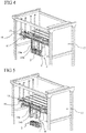
- a clamp (6) is also equipped with a vertical release means (14) of a wedging element (2), which is presented, as shown in the figure. figure 4 , by two lateral support points (14a), arranged inside the jaws (7) and advantageously of a central support point (14b).
- a suitable mechanism moves either the jaws (7) or the vertical release means (14) relative to each other in a vertical manner, in order to release a wedge member (2).
- the jaws (7) are fixed along the vertical axis (Z, Z ') relative to the rails (13) which carry them, while the vertical release means (14) is movable along the vertical axis (Z, Z '), but it could be otherwise, the vertical release means (14) is fixed along the vertical axis (Z, Z') with respect to the rails (13) which carries it, while the jaws (7) are movable along the vertical axis (Z, Z '), as illustrated in figures 4 to 6c .
- the vertical release means (14) is fixed to the rail set (13), while the jaws (7) are connected to the outside of the vertical release means (14) by slides.
- the jaws (7) are equipped with lower stops (15) arranged at their upper ends, which extend transversely outwards along the transverse axis (X, X '). These lower stops (15) are intended to interact with cross members (16) arranged between the plates (17),
- the descent of a clamp by the descent of the rail set (13), induces the interaction of the bottom stops (15) with the cross members (16), the jaws (7) remaining blocked at the level cross members (16), while the vertical release means (14) continues its downward stroke, releasing a wedging member (2) in the supported carton, as shown in figure figure 5 , and illustrated in more detail in figures 6a to 6c .
- a wedging element (2) is advantageously produced on demand by a distributor, distributed on a cassette (8), compressed by a clamp (6), which moves it vertically and released by the vertical release means (14). , in view of its positioning in a box (C), in which it adopts a partially compressed shape, allowing it to be held in position against at least one pair of flaps, preferably the short flaps (RC), but it could be otherwise, a wedging element (2) is held in position by the ends of the so-called short side walls.
- This positioning ensures that a gripping means, during its descent, does not damage one or more articles placed in a box.
- the long flaps (RL) are therefore positioned partially open, so that the insertion of the wedging element (2) in a box, does not does not abut the end of a long flap (RL), or even closes a long flap (RL) in an unwanted manner.
- At least one packaging device (1) allows the superposition of at least one wedging element (2) on the surface of at least one article, prior to sending by the conveyor (4). from the carton to preferably a sealer, for closing and sealing the carton.
- the closing of the flaps or the placement of a cover allows at least one wedging element (2) to substantially conform to the shape of at least one article and to fill the empty spaces above the latter.
- the invention also relates to a method of implementing the packaging device (1) as defined in claim 12.
- the methods according to embodiments include a step of positioning at least one wedging element (2) under stress against at least the ends of two side walls arranged in opposition, preferably also against the flaps arranged along axes. transverse (X, X '), preferably the short flaps (RC).
- At least the management of the centering at the zero point of a box along the longitudinal axis (Y, Y '), by the first arm (10a) and the second arm (10b), as well as along the transverse axis (X, X '), by the stops (9a, 9b), can be achieved according to at least three operating modes.
Landscapes
- Engineering & Computer Science (AREA)
- Mechanical Engineering (AREA)
- Robotics (AREA)
- Microelectronics & Electronic Packaging (AREA)
- Container Filling Or Packaging Operations (AREA)
- Supplying Of Containers To The Packaging Station (AREA)
Applications Claiming Priority (2)
| Application Number | Priority Date | Filing Date | Title |
|---|---|---|---|
| FR1654813A FR3051774B1 (fr) | 2016-05-27 | 2016-05-27 | Dispositif d'empaquetage d'element de calage dans un carton |
| PCT/FR2017/051285 WO2017203169A1 (fr) | 2016-05-27 | 2017-05-24 | Dispositif et procede d'empaquetage d'element de calage dans un carton |
Publications (2)
| Publication Number | Publication Date |
|---|---|
| EP3464080A1 EP3464080A1 (fr) | 2019-04-10 |
| EP3464080B1 true EP3464080B1 (fr) | 2021-03-03 |
Family
ID=56404208
Family Applications (1)
| Application Number | Title | Priority Date | Filing Date |
|---|---|---|---|
| EP17732972.9A Active EP3464080B1 (fr) | 2016-05-27 | 2017-05-24 | Dispositif et procede d'empaquetage d'element de calage dans un carton |
Country Status (7)
| Country | Link |
|---|---|
| US (1) | US11053041B2 (enExample) |
| EP (1) | EP3464080B1 (enExample) |
| JP (1) | JP6941384B2 (enExample) |
| BR (1) | BR112018074310B1 (enExample) |
| CA (1) | CA3025642A1 (enExample) |
| FR (1) | FR3051774B1 (enExample) |
| WO (1) | WO2017203169A1 (enExample) |
Cited By (1)
| Publication number | Priority date | Publication date | Assignee | Title |
|---|---|---|---|---|
| DE102023116782A1 (de) | 2023-06-26 | 2025-01-02 | Sprick Gmbh Bielefelder Papier- Und Wellpappenwerke & Co. | Packmaterialverarbeitungsstation sowie Verfahren zum Betreiben einer Packmaterialverarbeitungsstation |
Families Citing this family (15)
| Publication number | Priority date | Publication date | Assignee | Title |
|---|---|---|---|---|
| DE102017109375A1 (de) | 2017-05-02 | 2018-11-08 | Storopack Hans Reichenecker Gmbh | Verfahren zum Polstern von Gegenständen in einem Behälter, sowie Vorrichtung zum Polstern von Gegenständen in einem Behälter |
| CN108820349A (zh) * | 2018-06-30 | 2018-11-16 | 芜湖拓达电子科技有限公司 | 一种快递货物包装填充平台 |
| CN108820385B (zh) * | 2018-07-13 | 2024-09-20 | 武汉智能装备工业技术研究院有限公司 | 一种缓冲气垫材料的智能填充装置 |
| CN109202007A (zh) * | 2018-09-27 | 2019-01-15 | 江苏天毅冷镦股份有限公司 | 一种通过伺服电机改变方向的冷镦机传送机构 |
| CN111252310A (zh) * | 2020-01-17 | 2020-06-09 | 佛山普瑞威尔科技有限公司 | 一种芯片加工出料用缓冲垫放置装置 |
| CN111169746B (zh) * | 2020-03-03 | 2020-10-02 | 浙江亿钛数控机械有限公司 | 一种纸箱包装中泡沫自动装填机械 |
| DK180737B1 (en) * | 2020-07-06 | 2022-02-10 | Marel Iceland Ehf | A system and a method for automatically placing ice into boxes having two or more different widths |
| US11897652B2 (en) * | 2020-09-29 | 2024-02-13 | Dish Network L.L.C. | Devices, systems and processes for facilitating opening of boxes |
| CN113120340B (zh) * | 2021-03-15 | 2022-12-30 | 西交思创自动化科技有限公司 | 一种高压断路装置自动化包装生产线 |
| KR20240000466A (ko) * | 2021-04-28 | 2024-01-02 | 가부시끼가이샤 도꾸야마 | 지그 및 다결정 실리콘 상자포장체의 제조 방법 |
| CN113371257B (zh) * | 2021-07-02 | 2023-11-17 | 宁波金田新材料有限公司 | 一种电磁线自动装箱包装线 |
| CN114802923A (zh) * | 2022-05-25 | 2022-07-29 | 嘉兴雁荡包装有限公司 | 一种纸杯自动装箱机及装箱方法 |
| DE102023116783A1 (de) | 2023-06-26 | 2025-01-02 | Sprick Gmbh Bielefelder Papier- Und Wellpappenwerke & Co. | Anordnung und Verfahren zum Füllen von Hohlräumen in Transportbehältern mit Polstereinheiten aus Papier |
| CN117550167A (zh) * | 2023-12-22 | 2024-02-13 | 海安市春华线业有限公司 | 一种自动收纳包装的机械加工装置 |
| CN118928896B (zh) * | 2024-09-02 | 2025-05-02 | 深圳市瀚达美电子股份有限公司 | 一种车载背光源生产用打包装置 |
Family Cites Families (29)
| Publication number | Priority date | Publication date | Assignee | Title |
|---|---|---|---|---|
| US3381452A (en) * | 1965-12-22 | 1968-05-07 | Mead Corp | Machine for placing inserts into loaded article carriers |
| CA919080A (en) * | 1968-10-31 | 1973-01-16 | Aci Operations Pty, Ltd | Packaging of bottles, jars and other articles |
| JPS6010994B2 (ja) * | 1976-12-27 | 1985-03-22 | 帝人株式会社 | 板状体の移送装置 |
| IT1236204B (it) * | 1989-11-08 | 1993-01-19 | Apparecchiatura automatica con unico dispositivo di presa per strutture divisorie od "alveari" da estrarre aprire ed inserire in successionein contenitori o "cartoni" per bottiglie e simili. | |
| JPH06102445B2 (ja) * | 1990-02-15 | 1994-12-14 | 株式会社ミューチュアル | 包装機におけるカートンの寸法自動設定方法 |
| FR2683515B1 (fr) * | 1991-11-07 | 1994-11-18 | Windmoeller & Hoelscher | Appareil pour saisir et transporter des piles d'objets plats. |
| US5829231A (en) * | 1996-11-14 | 1998-11-03 | Ranpak Corporation | Automated cushioning producing and filling system |
| CA2293647A1 (en) * | 1997-06-11 | 1998-12-17 | Ranpak Corp. | Cushioning conversion system and method |
| WO2002064358A2 (en) * | 2000-10-20 | 2002-08-22 | Ranpak Corp. | Cushioning conversion system with dunnage pad transfer mechanism |
| ES2217907B1 (es) * | 2001-10-29 | 2006-01-16 | Pedro Serras Vila | Maquina para dispensar automaticamente divisiones protectoras y separadoras de grupos de botellas para cadenas de embalaje de las mismas. |
| JP2003300510A (ja) * | 2002-04-09 | 2003-10-21 | Fuji Photo Film Co Ltd | 製品の自動包装方法および装置 |
| US20040052988A1 (en) | 2002-09-17 | 2004-03-18 | Jean-Marc Slovencik | Cushioning product and method and apparatus for making same |
| ITMO20020298A1 (it) | 2002-10-16 | 2004-04-17 | Bartolin Kemo S P A | Macchina per il confezionamento di cartoni contenenti |
| US7133994B2 (en) | 2003-04-17 | 2006-11-07 | International Business Machines Corporation | Configuration size determination in logically partitioned environment |
| ATE471278T1 (de) * | 2004-11-05 | 2010-07-15 | Ranpak Corp | Automatisiertes system und verfahren zum füllen mit garniermaterial |
| US7665275B2 (en) | 2005-02-18 | 2010-02-23 | Ranpak Corp. | Packaging system with dunnage delivery assembly |
| EP2013086B1 (en) | 2006-04-10 | 2010-06-02 | Ranpak Corp. | Packaging system with volume measurement |
| GB0812233D0 (en) * | 2008-07-04 | 2008-08-13 | Meadwestvaco Packaging Systems | Packaging machine and method of packaging articles |
| KR101688885B1 (ko) * | 2008-11-24 | 2016-12-23 | 랜팩 코포레이션 | 공동 충전 포장 시스템, 완충재의 양 제어 방법, 포장 용기의 높이 치수 결정 방법, 및 포장 용기의 높이 근사치 결정 방법 |
| IT1392529B1 (it) | 2008-12-31 | 2012-03-09 | Corradi | Apparecchiatura per l'erogazione e l'inserimento di materiale per imballaggio in contenitori e relativo metodo. |
| AR077777A1 (es) * | 2010-07-29 | 2011-09-21 | Lattanzi Fernando Adrian | Maquina colocadora de separadores protectores de botellas contenidas en cajas de embalaje |
| US9399529B2 (en) * | 2010-08-09 | 2016-07-26 | Pack Flow Concepts Llc | Automated product engager, transporter and patterened depositor system |
| EP2682344B1 (de) * | 2012-07-06 | 2016-05-04 | api Computerhandels GmbH | Verfahren zum Verpacken in eine Umverpackung mit Einsatz |
| DE102013108177A1 (de) * | 2013-07-30 | 2015-02-05 | Khs Gmbh | Vorrichtung zum Transportieren und Einsetzen von Trennelementen in Verpackungseinheiten |
| DE102014008108A1 (de) * | 2014-06-02 | 2015-12-03 | Liebherr-Verzahntechnik Gmbh | Vorrichtung zum automatisierten Entnehmen von in einem Behälter angeordneten Werkstücken |
| US9840347B1 (en) * | 2014-12-17 | 2017-12-12 | X Development LLX | Adhering modular elements for packaging structures |
| DE102017109375A1 (de) * | 2017-05-02 | 2018-11-08 | Storopack Hans Reichenecker Gmbh | Verfahren zum Polstern von Gegenständen in einem Behälter, sowie Vorrichtung zum Polstern von Gegenständen in einem Behälter |
| US11865714B2 (en) * | 2019-02-17 | 2024-01-09 | Samsung Electronics Co., Ltd. | Robotic limb |
| US10639790B1 (en) * | 2019-08-12 | 2020-05-05 | Aaron Thomas Bacon | Robotic gripper |
-
2016
- 2016-05-27 FR FR1654813A patent/FR3051774B1/fr active Active
-
2017
- 2017-05-24 EP EP17732972.9A patent/EP3464080B1/fr active Active
- 2017-05-24 CA CA3025642A patent/CA3025642A1/fr active Pending
- 2017-05-24 JP JP2019514866A patent/JP6941384B2/ja active Active
- 2017-05-24 BR BR112018074310-0A patent/BR112018074310B1/pt active IP Right Grant
- 2017-05-24 US US16/304,671 patent/US11053041B2/en active Active
- 2017-05-24 WO PCT/FR2017/051285 patent/WO2017203169A1/fr not_active Ceased
Non-Patent Citations (1)
| Title |
|---|
| None * |
Cited By (2)
| Publication number | Priority date | Publication date | Assignee | Title |
|---|---|---|---|---|
| DE102023116782A1 (de) | 2023-06-26 | 2025-01-02 | Sprick Gmbh Bielefelder Papier- Und Wellpappenwerke & Co. | Packmaterialverarbeitungsstation sowie Verfahren zum Betreiben einer Packmaterialverarbeitungsstation |
| WO2025003266A1 (de) | 2023-06-26 | 2025-01-02 | Sprick Gmbh Bielefelder Papier- Und Wellpappenwerke & Co. | Packmaterialverarbeitungsstation sowie verfahren zum betreiben einer packmaterialverarbeitungsstation |
Also Published As
| Publication number | Publication date |
|---|---|
| BR112018074310A2 (pt) | 2019-03-12 |
| US20200324929A1 (en) | 2020-10-15 |
| BR112018074310B1 (pt) | 2022-10-25 |
| JP6941384B2 (ja) | 2021-09-29 |
| CA3025642A1 (fr) | 2017-11-30 |
| US11053041B2 (en) | 2021-07-06 |
| WO2017203169A1 (fr) | 2017-11-30 |
| FR3051774A1 (fr) | 2017-12-01 |
| FR3051774B1 (fr) | 2020-10-09 |
| JP2019517963A (ja) | 2019-06-27 |
| EP3464080A1 (fr) | 2019-04-10 |
Similar Documents
| Publication | Publication Date | Title |
|---|---|---|
| EP3464080B1 (fr) | Dispositif et procede d'empaquetage d'element de calage dans un carton | |
| EP3464078B1 (fr) | Tete de saisie et de pliage de feuilles d'encart, dispositif d'encartage, station de remplissage et procede de saisie, pliage et chargement d'une feuille d'encart | |
| US9789985B2 (en) | Packaging aid, packing method and packing workplace | |
| EP3033223B1 (fr) | Procede et dispositif de mise en place de renforts sur une decoupe d'emballage en carton | |
| EP3110699B1 (fr) | Procédé et machine pour fermer des boîtes à section carrée ou rectangulaire en réduisant leur hauteur à celle de leur contenu | |
| CN103732499B (zh) | 用于打开和转移折叠平整并直立放置的包装壳的装置及方法 | |
| EP3464075B1 (fr) | Dispositif vibrateur pour le rearrangement ordonne de boites pliantes dans un recipient, convoyeur d'evacuation et procede d'evacuation de recipients | |
| FR2547277A1 (fr) | Dispositif de pliage et de fermeture pour machine d'emballage en carton | |
| CN103391881A (zh) | 用于包装物品的装置及方法 | |
| US12492029B2 (en) | Packaging system and method for feeding flat packaging materials to a packaging system | |
| EP3263469B1 (fr) | Machine d'extraction, de mise en volume, de remplissage et de fermeture de caisse americaine | |
| EP0645309A1 (fr) | Procédé et dispositif pour adapter la hauteur d'un emballage à la hauteur de son contenu et dispositif de coupe pour la mise en oeuvre | |
| WO2021052961A1 (fr) | Dispositif et procede de formage de conteneur par pliage | |
| JP7294628B2 (ja) | 果菜自動箱詰め排出方法、果菜収容箱自動積み重ね排出方法、果菜自動箱詰め排出装置、果菜収容箱自動積み重ね排出装置 | |
| FR2781471A1 (fr) | Dispositif de palettisation comprenant une alimentation de palettes vides par le haut | |
| FR2926287A1 (fr) | Dispositif d'emballage | |
| CN120303187A (zh) | 容器自动装载及包装装置及方法 | |
| EP0384869B1 (fr) | Procédé et appareil pour empiler des articles cylindriques couches sur un support plat, notamment sur une palette | |
| JPH07115695B2 (ja) | 段差を有する物品を集積した包装物の開封方法及びその装置 | |
| EP3867157B1 (fr) | Dispositif et procédé de rassemblement et de déchargement d'articles | |
| KR102849094B1 (ko) | 낱개 포장물을 필로우 포장백에 포장하기 위한 수평형 필로우 포장기 | |
| KR102591188B1 (ko) | 제품 장입 및 박스 포장장치 | |
| EP0850179A1 (fr) | Procede de palettisation avec renfort de resistance a la compression | |
| KR102668719B1 (ko) | 패키징 시스템 | |
| CN117460671A (zh) | 将一个以上物品包装在箱子中的包装方法和系统 |
Legal Events
| Date | Code | Title | Description |
|---|---|---|---|
| STAA | Information on the status of an ep patent application or granted ep patent |
Free format text: STATUS: UNKNOWN |
|
| STAA | Information on the status of an ep patent application or granted ep patent |
Free format text: STATUS: THE INTERNATIONAL PUBLICATION HAS BEEN MADE |
|
| PUAI | Public reference made under article 153(3) epc to a published international application that has entered the european phase |
Free format text: ORIGINAL CODE: 0009012 |
|
| STAA | Information on the status of an ep patent application or granted ep patent |
Free format text: STATUS: REQUEST FOR EXAMINATION WAS MADE |
|
| 17P | Request for examination filed |
Effective date: 20181220 |
|
| AK | Designated contracting states |
Kind code of ref document: A1 Designated state(s): AL AT BE BG CH CY CZ DE DK EE ES FI FR GB GR HR HU IE IS IT LI LT LU LV MC MK MT NL NO PL PT RO RS SE SI SK SM TR |
|
| AX | Request for extension of the european patent |
Extension state: BA ME |
|
| DAV | Request for validation of the european patent (deleted) | ||
| DAX | Request for extension of the european patent (deleted) | ||
| STAA | Information on the status of an ep patent application or granted ep patent |
Free format text: STATUS: EXAMINATION IS IN PROGRESS |
|
| 17Q | First examination report despatched |
Effective date: 20200110 |
|
| REG | Reference to a national code |
Ref country code: DE Ref legal event code: R079 Ref document number: 602017033808 Country of ref document: DE Free format text: PREVIOUS MAIN CLASS: B65B0061220000 Ipc: B65B0063020000 |
|
| GRAP | Despatch of communication of intention to grant a patent |
Free format text: ORIGINAL CODE: EPIDOSNIGR1 |
|
| STAA | Information on the status of an ep patent application or granted ep patent |
Free format text: STATUS: GRANT OF PATENT IS INTENDED |
|
| RIC1 | Information provided on ipc code assigned before grant |
Ipc: B25J 9/02 20060101ALI20201104BHEP Ipc: B25J 9/00 20060101ALI20201104BHEP Ipc: B65B 55/20 20060101ALI20201104BHEP Ipc: B65B 63/02 20060101AFI20201104BHEP Ipc: B25J 15/00 20060101ALI20201104BHEP Ipc: B65B 43/52 20060101ALI20201104BHEP Ipc: B25J 15/02 20060101ALI20201104BHEP |
|
| INTG | Intention to grant announced |
Effective date: 20201123 |
|
| GRAS | Grant fee paid |
Free format text: ORIGINAL CODE: EPIDOSNIGR3 |
|
| GRAA | (expected) grant |
Free format text: ORIGINAL CODE: 0009210 |
|
| STAA | Information on the status of an ep patent application or granted ep patent |
Free format text: STATUS: THE PATENT HAS BEEN GRANTED |
|
| AK | Designated contracting states |
Kind code of ref document: B1 Designated state(s): AL AT BE BG CH CY CZ DE DK EE ES FI FR GB GR HR HU IE IS IT LI LT LU LV MC MK MT NL NO PL PT RO RS SE SI SK SM TR |
|
| REG | Reference to a national code |
Ref country code: GB Ref legal event code: FG4D Free format text: NOT ENGLISH |
|
| REG | Reference to a national code |
Ref country code: AT Ref legal event code: REF Ref document number: 1366971 Country of ref document: AT Kind code of ref document: T Effective date: 20210315 Ref country code: CH Ref legal event code: EP |
|
| REG | Reference to a national code |
Ref country code: DE Ref legal event code: R096 Ref document number: 602017033808 Country of ref document: DE |
|
| REG | Reference to a national code |
Ref country code: IE Ref legal event code: FG4D Free format text: LANGUAGE OF EP DOCUMENT: FRENCH |
|
| REG | Reference to a national code |
Ref country code: CH Ref legal event code: NV Representative=s name: SIVIER, CH |
|
| REG | Reference to a national code |
Ref country code: LT Ref legal event code: MG9D |
|
| PG25 | Lapsed in a contracting state [announced via postgrant information from national office to epo] |
Ref country code: NO Free format text: LAPSE BECAUSE OF FAILURE TO SUBMIT A TRANSLATION OF THE DESCRIPTION OR TO PAY THE FEE WITHIN THE PRESCRIBED TIME-LIMIT Effective date: 20210603 Ref country code: HR Free format text: LAPSE BECAUSE OF FAILURE TO SUBMIT A TRANSLATION OF THE DESCRIPTION OR TO PAY THE FEE WITHIN THE PRESCRIBED TIME-LIMIT Effective date: 20210303 Ref country code: FI Free format text: LAPSE BECAUSE OF FAILURE TO SUBMIT A TRANSLATION OF THE DESCRIPTION OR TO PAY THE FEE WITHIN THE PRESCRIBED TIME-LIMIT Effective date: 20210303 Ref country code: GR Free format text: LAPSE BECAUSE OF FAILURE TO SUBMIT A TRANSLATION OF THE DESCRIPTION OR TO PAY THE FEE WITHIN THE PRESCRIBED TIME-LIMIT Effective date: 20210604 Ref country code: LT Free format text: LAPSE BECAUSE OF FAILURE TO SUBMIT A TRANSLATION OF THE DESCRIPTION OR TO PAY THE FEE WITHIN THE PRESCRIBED TIME-LIMIT Effective date: 20210303 Ref country code: BG Free format text: LAPSE BECAUSE OF FAILURE TO SUBMIT A TRANSLATION OF THE DESCRIPTION OR TO PAY THE FEE WITHIN THE PRESCRIBED TIME-LIMIT Effective date: 20210603 |
|
| REG | Reference to a national code |
Ref country code: NL Ref legal event code: MP Effective date: 20210303 |
|
| REG | Reference to a national code |
Ref country code: AT Ref legal event code: MK05 Ref document number: 1366971 Country of ref document: AT Kind code of ref document: T Effective date: 20210303 |
|
| PG25 | Lapsed in a contracting state [announced via postgrant information from national office to epo] |
Ref country code: SE Free format text: LAPSE BECAUSE OF FAILURE TO SUBMIT A TRANSLATION OF THE DESCRIPTION OR TO PAY THE FEE WITHIN THE PRESCRIBED TIME-LIMIT Effective date: 20210303 Ref country code: RS Free format text: LAPSE BECAUSE OF FAILURE TO SUBMIT A TRANSLATION OF THE DESCRIPTION OR TO PAY THE FEE WITHIN THE PRESCRIBED TIME-LIMIT Effective date: 20210303 Ref country code: PL Free format text: LAPSE BECAUSE OF FAILURE TO SUBMIT A TRANSLATION OF THE DESCRIPTION OR TO PAY THE FEE WITHIN THE PRESCRIBED TIME-LIMIT Effective date: 20210303 Ref country code: LV Free format text: LAPSE BECAUSE OF FAILURE TO SUBMIT A TRANSLATION OF THE DESCRIPTION OR TO PAY THE FEE WITHIN THE PRESCRIBED TIME-LIMIT Effective date: 20210303 |
|
| PG25 | Lapsed in a contracting state [announced via postgrant information from national office to epo] |
Ref country code: NL Free format text: LAPSE BECAUSE OF FAILURE TO SUBMIT A TRANSLATION OF THE DESCRIPTION OR TO PAY THE FEE WITHIN THE PRESCRIBED TIME-LIMIT Effective date: 20210303 |
|
| PG25 | Lapsed in a contracting state [announced via postgrant information from national office to epo] |
Ref country code: AT Free format text: LAPSE BECAUSE OF FAILURE TO SUBMIT A TRANSLATION OF THE DESCRIPTION OR TO PAY THE FEE WITHIN THE PRESCRIBED TIME-LIMIT Effective date: 20210303 Ref country code: SM Free format text: LAPSE BECAUSE OF FAILURE TO SUBMIT A TRANSLATION OF THE DESCRIPTION OR TO PAY THE FEE WITHIN THE PRESCRIBED TIME-LIMIT Effective date: 20210303 Ref country code: EE Free format text: LAPSE BECAUSE OF FAILURE TO SUBMIT A TRANSLATION OF THE DESCRIPTION OR TO PAY THE FEE WITHIN THE PRESCRIBED TIME-LIMIT Effective date: 20210303 Ref country code: CZ Free format text: LAPSE BECAUSE OF FAILURE TO SUBMIT A TRANSLATION OF THE DESCRIPTION OR TO PAY THE FEE WITHIN THE PRESCRIBED TIME-LIMIT Effective date: 20210303 |
|
| PG25 | Lapsed in a contracting state [announced via postgrant information from national office to epo] |
Ref country code: SK Free format text: LAPSE BECAUSE OF FAILURE TO SUBMIT A TRANSLATION OF THE DESCRIPTION OR TO PAY THE FEE WITHIN THE PRESCRIBED TIME-LIMIT Effective date: 20210303 Ref country code: RO Free format text: LAPSE BECAUSE OF FAILURE TO SUBMIT A TRANSLATION OF THE DESCRIPTION OR TO PAY THE FEE WITHIN THE PRESCRIBED TIME-LIMIT Effective date: 20210303 Ref country code: PT Free format text: LAPSE BECAUSE OF FAILURE TO SUBMIT A TRANSLATION OF THE DESCRIPTION OR TO PAY THE FEE WITHIN THE PRESCRIBED TIME-LIMIT Effective date: 20210705 Ref country code: IS Free format text: LAPSE BECAUSE OF FAILURE TO SUBMIT A TRANSLATION OF THE DESCRIPTION OR TO PAY THE FEE WITHIN THE PRESCRIBED TIME-LIMIT Effective date: 20210703 |
|
| REG | Reference to a national code |
Ref country code: DE Ref legal event code: R097 Ref document number: 602017033808 Country of ref document: DE |
|
| PLBE | No opposition filed within time limit |
Free format text: ORIGINAL CODE: 0009261 |
|
| STAA | Information on the status of an ep patent application or granted ep patent |
Free format text: STATUS: NO OPPOSITION FILED WITHIN TIME LIMIT |
|
| PG25 | Lapsed in a contracting state [announced via postgrant information from national office to epo] |
Ref country code: ES Free format text: LAPSE BECAUSE OF FAILURE TO SUBMIT A TRANSLATION OF THE DESCRIPTION OR TO PAY THE FEE WITHIN THE PRESCRIBED TIME-LIMIT Effective date: 20210303 Ref country code: AL Free format text: LAPSE BECAUSE OF FAILURE TO SUBMIT A TRANSLATION OF THE DESCRIPTION OR TO PAY THE FEE WITHIN THE PRESCRIBED TIME-LIMIT Effective date: 20210303 Ref country code: DK Free format text: LAPSE BECAUSE OF FAILURE TO SUBMIT A TRANSLATION OF THE DESCRIPTION OR TO PAY THE FEE WITHIN THE PRESCRIBED TIME-LIMIT Effective date: 20210303 Ref country code: MC Free format text: LAPSE BECAUSE OF FAILURE TO SUBMIT A TRANSLATION OF THE DESCRIPTION OR TO PAY THE FEE WITHIN THE PRESCRIBED TIME-LIMIT Effective date: 20210303 Ref country code: LU Free format text: LAPSE BECAUSE OF NON-PAYMENT OF DUE FEES Effective date: 20210524 |
|
| 26N | No opposition filed |
Effective date: 20211206 |
|
| REG | Reference to a national code |
Ref country code: BE Ref legal event code: MM Effective date: 20210531 |
|
| GBPC | Gb: european patent ceased through non-payment of renewal fee |
Effective date: 20210603 |
|
| PG25 | Lapsed in a contracting state [announced via postgrant information from national office to epo] |
Ref country code: SI Free format text: LAPSE BECAUSE OF FAILURE TO SUBMIT A TRANSLATION OF THE DESCRIPTION OR TO PAY THE FEE WITHIN THE PRESCRIBED TIME-LIMIT Effective date: 20210303 |
|
| PG25 | Lapsed in a contracting state [announced via postgrant information from national office to epo] |
Ref country code: IT Free format text: LAPSE BECAUSE OF FAILURE TO SUBMIT A TRANSLATION OF THE DESCRIPTION OR TO PAY THE FEE WITHIN THE PRESCRIBED TIME-LIMIT Effective date: 20210303 Ref country code: IE Free format text: LAPSE BECAUSE OF NON-PAYMENT OF DUE FEES Effective date: 20210524 Ref country code: GB Free format text: LAPSE BECAUSE OF NON-PAYMENT OF DUE FEES Effective date: 20210603 |
|
| PG25 | Lapsed in a contracting state [announced via postgrant information from national office to epo] |
Ref country code: IS Free format text: LAPSE BECAUSE OF FAILURE TO SUBMIT A TRANSLATION OF THE DESCRIPTION OR TO PAY THE FEE WITHIN THE PRESCRIBED TIME-LIMIT Effective date: 20210703 |
|
| PG25 | Lapsed in a contracting state [announced via postgrant information from national office to epo] |
Ref country code: BE Free format text: LAPSE BECAUSE OF NON-PAYMENT OF DUE FEES Effective date: 20210531 |
|
| PG25 | Lapsed in a contracting state [announced via postgrant information from national office to epo] |
Ref country code: CY Free format text: LAPSE BECAUSE OF FAILURE TO SUBMIT A TRANSLATION OF THE DESCRIPTION OR TO PAY THE FEE WITHIN THE PRESCRIBED TIME-LIMIT Effective date: 20210303 |
|
| PG25 | Lapsed in a contracting state [announced via postgrant information from national office to epo] |
Ref country code: HU Free format text: LAPSE BECAUSE OF FAILURE TO SUBMIT A TRANSLATION OF THE DESCRIPTION OR TO PAY THE FEE WITHIN THE PRESCRIBED TIME-LIMIT; INVALID AB INITIO Effective date: 20170524 |
|
| PG25 | Lapsed in a contracting state [announced via postgrant information from national office to epo] |
Ref country code: MK Free format text: LAPSE BECAUSE OF FAILURE TO SUBMIT A TRANSLATION OF THE DESCRIPTION OR TO PAY THE FEE WITHIN THE PRESCRIBED TIME-LIMIT Effective date: 20210303 |
|
| PG25 | Lapsed in a contracting state [announced via postgrant information from national office to epo] |
Ref country code: TR Free format text: LAPSE BECAUSE OF FAILURE TO SUBMIT A TRANSLATION OF THE DESCRIPTION OR TO PAY THE FEE WITHIN THE PRESCRIBED TIME-LIMIT Effective date: 20210303 |
|
| PG25 | Lapsed in a contracting state [announced via postgrant information from national office to epo] |
Ref country code: MT Free format text: LAPSE BECAUSE OF FAILURE TO SUBMIT A TRANSLATION OF THE DESCRIPTION OR TO PAY THE FEE WITHIN THE PRESCRIBED TIME-LIMIT Effective date: 20210303 |
|
| PGFP | Annual fee paid to national office [announced via postgrant information from national office to epo] |
Ref country code: DE Payment date: 20250513 Year of fee payment: 9 |
|
| PGFP | Annual fee paid to national office [announced via postgrant information from national office to epo] |
Ref country code: FR Payment date: 20250429 Year of fee payment: 9 |
|
| PGFP | Annual fee paid to national office [announced via postgrant information from national office to epo] |
Ref country code: CH Payment date: 20250601 Year of fee payment: 9 |