EP3463090B1 - Grille d'anti-diffusion pour imagerie à rayons x à source multiples (quasi)-isotrope compacte - Google Patents
Grille d'anti-diffusion pour imagerie à rayons x à source multiples (quasi)-isotrope compacte Download PDFInfo
- Publication number
- EP3463090B1 EP3463090B1 EP17727868.6A EP17727868A EP3463090B1 EP 3463090 B1 EP3463090 B1 EP 3463090B1 EP 17727868 A EP17727868 A EP 17727868A EP 3463090 B1 EP3463090 B1 EP 3463090B1
- Authority
- EP
- European Patent Office
- Prior art keywords
- ray
- strips
- imaging apparatus
- asg
- sets
- Prior art date
- Legal status (The legal status is an assumption and is not a legal conclusion. Google has not performed a legal analysis and makes no representation as to the accuracy of the status listed.)
- Active
Links
- 238000003384 imaging method Methods 0.000 title claims description 53
- 230000003287 optical effect Effects 0.000 claims description 12
- 230000005855 radiation Effects 0.000 description 11
- 239000000463 material Substances 0.000 description 10
- 230000002093 peripheral effect Effects 0.000 description 7
- 238000010521 absorption reaction Methods 0.000 description 6
- 239000000945 filler Substances 0.000 description 5
- 238000010276 construction Methods 0.000 description 4
- 239000003292 glue Substances 0.000 description 4
- 239000002131 composite material Substances 0.000 description 3
- 230000001419 dependent effect Effects 0.000 description 3
- 230000008901 benefit Effects 0.000 description 2
- 238000001914 filtration Methods 0.000 description 2
- 230000012447 hatching Effects 0.000 description 2
- 239000007937 lozenge Substances 0.000 description 2
- 238000004519 manufacturing process Methods 0.000 description 2
- 101000911772 Homo sapiens Hsc70-interacting protein Proteins 0.000 description 1
- 101001139126 Homo sapiens Krueppel-like factor 6 Proteins 0.000 description 1
- 230000009471 action Effects 0.000 description 1
- 239000000956 alloy Substances 0.000 description 1
- 229910045601 alloy Inorganic materials 0.000 description 1
- 239000004411 aluminium Substances 0.000 description 1
- 229910052782 aluminium Inorganic materials 0.000 description 1
- XAGFODPZIPBFFR-UHFFFAOYSA-N aluminium Chemical compound [Al] XAGFODPZIPBFFR-UHFFFAOYSA-N 0.000 description 1
- 230000009286 beneficial effect Effects 0.000 description 1
- 210000000988 bone and bone Anatomy 0.000 description 1
- 239000001913 cellulose Substances 0.000 description 1
- 229920002678 cellulose Polymers 0.000 description 1
- 230000008859 change Effects 0.000 description 1
- 238000006243 chemical reaction Methods 0.000 description 1
- 230000003247 decreasing effect Effects 0.000 description 1
- 230000000694 effects Effects 0.000 description 1
- 238000000605 extraction Methods 0.000 description 1
- 230000005484 gravity Effects 0.000 description 1
- 229910052751 metal Inorganic materials 0.000 description 1
- 239000002184 metal Substances 0.000 description 1
- 150000002739 metals Chemical class 0.000 description 1
- 238000000034 method Methods 0.000 description 1
- 239000000203 mixture Substances 0.000 description 1
- 230000001902 propagating effect Effects 0.000 description 1
- 238000002601 radiography Methods 0.000 description 1
- 230000008707 rearrangement Effects 0.000 description 1
- 230000004044 response Effects 0.000 description 1
- 238000005476 soldering Methods 0.000 description 1
- 230000002195 synergetic effect Effects 0.000 description 1
- WFKWXMTUELFFGS-UHFFFAOYSA-N tungsten Chemical compound [W] WFKWXMTUELFFGS-UHFFFAOYSA-N 0.000 description 1
- 229910052721 tungsten Inorganic materials 0.000 description 1
- 239000010937 tungsten Substances 0.000 description 1
- 238000011144 upstream manufacturing Methods 0.000 description 1
Images


Classifications
-
- A—HUMAN NECESSITIES
- A61—MEDICAL OR VETERINARY SCIENCE; HYGIENE
- A61B—DIAGNOSIS; SURGERY; IDENTIFICATION
- A61B6/00—Apparatus or devices for radiation diagnosis; Apparatus or devices for radiation diagnosis combined with radiation therapy equipment
- A61B6/42—Arrangements for detecting radiation specially adapted for radiation diagnosis
- A61B6/4291—Arrangements for detecting radiation specially adapted for radiation diagnosis the detector being combined with a grid or grating
-
- A—HUMAN NECESSITIES
- A61—MEDICAL OR VETERINARY SCIENCE; HYGIENE
- A61B—DIAGNOSIS; SURGERY; IDENTIFICATION
- A61B6/00—Apparatus or devices for radiation diagnosis; Apparatus or devices for radiation diagnosis combined with radiation therapy equipment
- A61B6/40—Arrangements for generating radiation specially adapted for radiation diagnosis
- A61B6/4007—Arrangements for generating radiation specially adapted for radiation diagnosis characterised by using a plurality of source units
-
- A—HUMAN NECESSITIES
- A61—MEDICAL OR VETERINARY SCIENCE; HYGIENE
- A61B—DIAGNOSIS; SURGERY; IDENTIFICATION
- A61B6/00—Apparatus or devices for radiation diagnosis; Apparatus or devices for radiation diagnosis combined with radiation therapy equipment
- A61B6/48—Diagnostic techniques
- A61B6/484—Diagnostic techniques involving phase contrast X-ray imaging
Definitions
- the invention relates to an X-ray imaging apparatus.
- Non-rotational multi-sources X-ray imagers can be used for 3D imaging without complicated mechanics required as in their rotational counterparts, such as C-arm imagers or CT.
- Anti-scatter grids are used in some of these multi-source X-ray imagers to reduce scatter.
- German patent DE545048 describes an X-ray anti-scatter grid comprising two piled together grids with different orientations.
- United States patent application US2009/147923 A1 describes an anti-scatter grid for medical x-ray devices comprising a number of first elements from a first material with second elements made from a second material integrated therein.
- an X-ray imaging apparatus having a plurality of X-ray sources comprising an anti-scatter grid for X-ray imaging comprising at least two sets of linear x-radiation opaque strips, each of the strips in the at least two sets having a respective longitudinal axis, wherein there are at least two strips from different sets of the at least two sets that have non-parallel longitudinal axes.
- At least one strip from one of the at least two sets is slanted or angled around its longitudinal axes relative to one other strip from said one of the at least two sets.
- the strips are focused on a line ("source line") in 3D space where an X-ray source is to be placed for which the respective set of strip can perform a scatter filtering function.
- the strips in at least one of the at least two sets form a plane.
- at least a part of the ASG may be planar or at least includes planar portions.
- the strips in at least one of the at least two sets form a curved surface.
- at least a part of the ASG is curved.
- the at least two sets are arranged in a common plane.
- a combination of plane and curved stets are likewise envisaged herein.
- the anti-scatter grid has at least n ⁇ 3 such sets, wherein the respective longitudinal axes of n strips from different ones of the at least n sets form a polygon with n vertices.
- the anti-scatter grid has three such sets, wherein the respective longitudinal axes of three strips from different ones of the at least three sets form a triangle.
- the anti-scatter grid has four of such sets, wherein the respective longitudinal axes of four strips from different ones of the at least four sets form a quadrangular.
- the anti-scatter grid is arranged in front of an X-ray detector of the imaging apparatus.
- they may be coupled to a housing of the detector.
- the at least three X-ray sources are positionable on a plane that does not intersect the detector.
- the anti-scatter grid is configured to directionally filter in respect of any one of the X-ray beams.
- the ASG can be used to reduce scatter in any of the beams propagating through the AGS along different directions from different positions of the X-ray sources.
- the at least one of the beams irradiates, at the same time, strips from different ones of the at least two of sets.
- ASG area is shared by the same beam.
- the strips are slanted relative to each other so as to focus the anti-scatter grid to a line ("source line”) passing through a focal spot of one of X-ray sources of the imaging apparatus.
- the strips from different ones of the at least two sets are focused to different source lines passing through the focal spots of different X-ray sources of the plurality of X-ray sources.
- the set of strips is focused towards a source lines that is parallel to the longitudinal axis of the strips in that set, and this source line is generally situated at a given distance away from a front face of the set. This distance may differ for different stets.
- Each set corresponds to different sub-grids or modules of the (composite or "super")-ASG.
- Having the strips from the at least two sets extend respectively along non-parallel longitudinal axes which allows definition of at least two intersecting source lines in 3D to establish one or more intersection points.
- the source lines are defined by the mutual angulation of the strips in the set. Positioning, as is done in one embodiment, sources on respective ones of these one or more intersection points allows sharing ASG area by a beam from said source.
- the same X-ray source can be scatter filtered by parts of the strips in different sets of which allows decreasing the footprint of the anti-scatter grid as there is no requirement to have a dedicated sub-area of the anti-scatter grid filter only for one and only one of the plurality of X-ray sources. This in turn leads to an overall more compact design of the whole imaging apparatus.
- the proposed grid is of particular application in systems where the plural sources are laid out in a 2-dimenstional configuration (rather than the sources being lined up in "1D" in a sequence along a straight or curved line) which usual yield a range of markedly different projection angles.
- a set of strips usually corresponds to a module or sub-grid of the ASG, but this is not necessarily so in all embodiments, where two (or more) sets of strips with their respective longitudinal axes at different orientations are part of the same/single module.
- the imaging apparatus IA comprises three or more X-ray sources sj (only three X-ray sources s1, s2 and s3 are shown but this is not limiting) operable to emit respective X-ray beams B1, B2 and B3 towards an X-ray detector D.
- a shape of the beams can be shaped by an optional pre-collimator (not shown).
- the beams Bj are preferably cone beam but fan beams are also envisaged.
- parallel projection beams may also be envisaged herein in alternative embodiments.
- the detector D comprises a radiation sensitive surface made up from detector pixels.
- an object to be imaged OB such as a human or animal patient or an anatomic part thereof supported on support surface SP such as a patient bed, examination table or the like.
- the imaging apparatus IA can be used for purely 2D projective radiography, 3D imaging is envisaged herein as a preferred embodiment.
- a plurality of different projection images ⁇ are acquired from different projection directions (corresponding to the different propagation directions of the X-ray beams B1-B3).
- the projection imagery ⁇ can then be reconstructed by available algorithms into a 3D image volume of that part of the object OB that resides in a volume of interest VOI.
- the VOI is defined as the intersection in 3D space of all beams or at least two thereof. It is not necessarily herein that all X-ray sources operate simultaneously. Imaging proceeds broadly as follows: the X-ray beams Bj travelling through the matter in the object OB are modified. It is this modified radiation that impinges on the detector pixels. The impinging radiation causes electrical signals (by direct or indirect conversion) at the individual detector pixels. The signals can be converted by AD circuitry into the respective projection images ⁇ .
- the X-ray imaging apparatus IA can be seen to be of a two dimensional wide angle multi-source imaging type. That is, the plural sources are not all linearly arranged in a sequence along a line (straight or curved) but define a layout in 2 dimensions around the object which requires relatively large projection angles differences as compared to a purely linear source layout. It uses in particular stationary X-ray sources, so the different sources are arranged in a fixed mechanical construction (such as a frame or the like) around the detector and are not rotational. Although it is envisaged in one embodiment that the sources are motorized or can be manually moved into different positions around the X-ray source, there is no motion during the imaging as is in the case in rotational systems such as CT or C-arm imaging. This allows reducing the mechanical overhead that these rotational systems necessitate. In simple embodiments the X-ray detectors are not moveable by the operator and are permanently fixed in a fixed geometrical arrangement around the object OB to be imaged.
- the digital X-ray detector D is in general a flat panel detector having a flat rectangular shape (as in Fig 1 ) in a housing which is suitably mounted above the object to be imaged.
- a detector with a curved radiation sensitive is also envisaged.
- the detector may be ceiling mounted, floor mounted as the case may be.
- Axes X,Y define a horizontal object plane on which resides the object OB to be imaged. That plane extends into the plane of the drawing in Figure 1 . Generally these axes are parallel to the respective edges of the patient support SP.
- an image plane defined by the detector D's radiation sensitive surface and in general this plane is parallel to the X,Y plane or at least to a tangent plane in case of a curved detector.
- a main optical axes Z of the imager Perpendicular to the image plane, through a central point of the detector sensitive surface and through the object plane runs a main optical axes Z of the imager. Ideally, this axis Z passes through the volume of interest VOI, preferably centrally.
- Spatio-relational terms as used herein such as “in front” or “behind”, “downstream”, “upstream”, etc will be taken relative to the propagation directions of the X-ray beams Bj.
- the X-ray sources sj are arranged opposite the detector D, across the examination region, Specifically, and in the (preferred) embodiment in Figure 1 , the sources sj are located (relative to the gravitational field) under the object OB (or object support SP) to be imaged whilst the detector is located above.
- the specific geometry shown in Figure 1 is not limiting, as a geometry reverse to the one shown in Figure 1 is also envisaged, where, relative to gravity, it is the detector that is mounted below the object or object support and, accordingly, the X-ray sources are mounted above (relative to the gravitational field) the object/support. It will be appreciated however, that the above introduced co-ordinate system and the spatial relational terms are invariant to such a re-arrangement and applicable to both of these embodiments.
- the X-ray sources sj are generally grouped around the main optical axis of the detector in a number of different (geometric) source configurations (as referred to herein as "source geometry") such as circular, elliptic or polygonal when viewed along the Z axis.
- the geometric source configuration may be defined by an envelope curve that passes through some (or all) source locations.
- one or more of the sources sj may be located inside the envelope curve formed by the remaining sources.
- the sources may be arranged linearly along a single or along plural lines.
- the geometric configuration is symmetric around the main optical axis Z through the VOI and at least some of the sources are preferably equi-angularly ("isotropic") distributed around the VOI/optical axis Z.
- equi-angular or isotropic arrangement around the VOI is the preferred spatial embodiment, quasi-isotropic arrangements are also envisaged herein where the source arrangement varies from a strict equi-angular arrangement.
- the source arrangement is preferably symmetric relative to the object but this is not necessarily so in all embodiments as asymmetric arrangements are also envisaged.
- the arrangement is asymmetric or merely quasi-isotropic, there is at least a symmetric or isotropic sub-set of sources.
- an otherwise isotropic or symmetric arrangement can be enlarged by placing additional sources on the source lines as required in different use scenarios.
- This (at least quasi-) isotropic source geometry has been found to allow good 3D reconstruction or 4D reconstruction (being a time series of 3D reconstructions).
- the X-ray sources sj are operable to project their respective beams Bj along different directions from below (or above) at an angle onto the X-radiation sensitive surface.
- the central source is located below the object OB/object support SP and on the central axis Z to emit a beam B along said axis Z.
- all the X-ray sources sj are located in a plane ("source plane") with the optical axis being normal to said plane although angular source planes are also envisaged herein.
- the VOI/object of interest does not intersect the source plane.
- the detector plane is different from the source plane, in particular the detector does not intersect said source plane.
- the sources sj are in general fixed and are not moveable although there are embodiments envisaged where at least one or more than one or all sources can be linearly translated and/or re-oriented to change the layout of the sources and hence the source geometry.
- the locations of the sources sj are not necessarily confined to a plane, but may be located at different z positions parallel to Z. For instance, sources with steeper (longer in-tissue path length of the beam) projection direction relative to the object OB may require stronger intensity sources and these may then be placed closer, "out-of-plane", to the patient than more distal, weaker sources.
- the imaging apparatus IA further comprises an anti-scatter grid ASG (which will likewise be referred to herein as ASG) which is situated in front of the detector, specifically between the object and detector D's X-ray sensitive surface.
- the anti-scatter grid forms a surface ("ASG surface") which is in general co-extensive in shape and size with that of the detector sensitive surface.
- the ASG can be a curved surface or a plane.
- the ASG is mounted on the detector itself, but this is not necessarily the case, or it is mounted spaced apart by mounting members away from the detector.
- the function of the ASG is to increase image quality.
- the signals detected at the detector D correspond to the attenuation (that is, the loss of intensity) experienced by the X-ray beams Bj as they pass through matter of the object OB to be imaged.
- this attenuation should be fully attributable to absorption events.
- not all of the attenuation is attributable to absorption (that is photo-electric absorption) as there is also a contribution from scatter.
- the electrical signals recorded in response to impinging X-ray radiation should be fully attributable to absorption.
- the function of the anti-scatter grid ASG then is to remove or at least diminish said scatter contribution.
- the AGS acts as a directional filter in respect of the X-ray beams B1-B3. More specifically, the ASG is configured to filter individual photons for a given source sj according to the trajectory orientation of the photons. That is, preferentially, X-rays emanating from the focal spot of source sj are capable of passing through the ASG while the ASG tends to at least partly block all other "rogue" X-rays that originate from scatter events.
- an irradiation volume can be defined by drawing a set of geometrical rays emanating from the focal spot FSj towards the detector.
- the anti-scatter grid is so configured that it allows only radiation to pass through it that travels along any of the geometrical lines within the predefined geometrical irradiation volume.
- the novel anti-scatter grid ASG as proposed herein is configured to perform its directional filter function as a single unity for any one of the different X-ray beams Bj emittable by the plurality of X-ray sources sj located at different locations in 3D space.
- the novel anti-scatter grid allows achieving detector area sharing, and it is configured to function as a joint or common, single ASG unit even when different ones of the X-ray sources use the same sub area or when there is an intersection of irradiated detector areas from different sources.
- the proposed anti-scatter grid ASG is envisaged as an assembly of different (that is 2 or more) grid parts or grid modules or panels Mj.
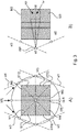
- Each module comprises a set or series of flat, radiation opaque strips or "lamellae". This set of discrete strips is formed from lead, tungsten or an alloy or from other metals or materials of suitably high Z materials to essentially block out X-ray. Because each module Mj is uniquely defined by its strips STj we will use the notation "Mj" interchangeably for the set of strips as well).
- the longitudinal strips STj are arranged in alternation with corresponding strips of buffer or filler material SB in between any two adjacent strips. Only three strips ST11, ST12, ST13 are shown for illustration in Figure 2 , it being understood that there are usually more than three strips).
- the buffer material SB is formed from X-ray radiation translucent material such as cellulose (eg, cardboard/paper) or aluminium or other. In other words, the buffer material is for structural integrity of the module but is configured to award essentially undisturbed passage through the ASG module.
- the buffer strips are in the order of 1/10 th of a Millimeter thick (eg, about 0.1-0.3 mm) but this number is merely an illustrative example.
- Each strip has a height, H, a thickness W and a longitudinal axis that extends along the longest edge.
- the strips are in one exemplary embodiment in the order of 100s of Milimeters long (eg, 400mm), about in the order of 1/100 th of a Millimeter thick (eg, 0.03mm) and about in the order of Millimeters high (eg, 2mm).
- the longitudinal axis of the different strips are shown as a LI, L3 (L2 is not shown).
- the longitudinal axes of the strips for a given module are parallel to each other.
- Some, but not necessarily all, of the strips are angled or slanted relative to each other and around their respective longitudinal axes as shown conceptually by angle ⁇ in Figure 2 .
- the strips are laid out in plane, that is, the longitudinal axes are all located in a plane.
- This arrangement gives rise to a flat or planar ASG module/panel.
- curved ASG modules Mj are also envisaged where the longitudinal axes although parallel, are not located in the same plane thus defining a non-planar or curved ASG grid module.
- each module Mi with its set of strips is associable with one of the plurality of X-ray sources sj. More specifically, and explaining the focusing geometry in more detail, each strip can be understood as a segment of a plane (focal plane) FPij in which this strip lies. It is also the respective longitudinal axis that lies in the respective plane. Because of the angulations, these planes FPij will intersect in a line that passes through the focal spot FSj of the associated X-ray source sj.
- the strip angulations and orientation of the strips' longitudinal axes uniquely determine the location in 3D of the source line sj.
- the orientation of the strips' longitudinal uniquely determine the orientation of the source line for a given grid module Mj. It is therefore apt and convenient to speak of a "source line orientation of module Mj".
- source line orientation of module Mj When two modules Mj,Mk in a given plane have different source line orientations this means that the longitudinal axes of their respective strips STi, STk are different, that is, they are non-parallel.
- a distance from the module to its source line slj may differ for different modules Mi.
- the strip angulations can be "symmetric" or "asymmetric".
- symmetric angulation (as shown in Figure 2 )
- the angulation of the remaining strips is the stronger, the further away the strip is located from the center strip, with all strips to the left of the center strip angulated clockwise whilst all strips to the right are angulated counter-clockwise.
- asymmetric angulation there is no non-angulated center strip, that is, all strips are angulated either counter-clockwise or clockwise.
- the orthogonal projection of its source line onto the plane of the module falls within the center of the module's Mj area (that is the area covered by its strips STj).
- asymmetric grid module allows defining its source line "away” or “sideways” from where the module Mj itself is located.
- the ASG proposed herein includes a plurality of such grid modules of the kind shown in Figure 2 arranged adjacent to each other to form the ASG as a single super-grid as it were. More specifically, it is proposed herein an ASG that includes a plurality of strip modules Mi such that there are at least two grid modules Mi, Mj with their respective strips having non-parallel longitudinal axes.
- the ASG is thus configured to generate different source lines and the very same ASG is capable of providing ASG functionality for a plurality of different X-ray sources whose focal spots are distributed in space, so long as any one of these focal spots of these sources lie on at least one of the source lines.
- a single ASG grid (made up as an assembly of modular grids Mj) can support very complicated source geometries distributed in 3D.
- the ASG is configured to produce intersecting source lines. Placing a source on an intersection point of two (or more) source lines allows sharing ASG area. In other words, a beam from the source at the intersection point is filtered jointly by the two modules that generate the intersecting source lines. This allows reducing the overall footprint of the ASG and hence of the imager as a whole.
- Figures 3-7 are illustrated a variety of source sj geometries, each with a respective supporting ASG strip geometry according to different embodiments all envisaged herein.
- FIG. 3 there is shown an ASG configured from multi-source imaging according to one embodiment.
- the overall layout of the ASG in plan view Z is rectangular, in particular, square, but any other quadrangular or polygonal or in fact circular or elliptic layout is also envisaged in alternative embodiments.
- the grid ASG is planar.
- the particular ASG shown in Figure 3 includes five sets M1-5 with different source line orientations.
- 4 modules M1-M4 are grouped around a center module M5.
- the course of the longitudinal axes of the strips are shown in this and the following figures 4-7 in different hatchings, with the orientation of the hatching representing the orientation of the longitudinal axes.
- the number of modules Mj per ASG is a function of the number of X-ray sources to be used. This number is less than or equal the number of sources. Because of the intersecting source lines and the fact that one can place several sources on the same source line, this number is preferably less.
- X-ray sources sj are shown as dots arranged in a circular source geometry around the axis Z of the grid.
- X-ray sources there are eight X-ray sources arranged around the axis Z with an additional, center, X-ray source, s8 arranged on the axis Z above or below the patient. This central source s8 affords imaging in AP (anterior-posterior) or PA view.
- Modules M2, M3 generate source lines sl2,sl3 of different orientation and thus have their strips run in non-parallel directions and so do Modules M1,M4.
- the opposing pairs modules M2,M4 and M3,M1 have source lines of respectively same orientation.
- Fig 3 is hence an embodiment where not all modules have source lines with different orientation.
- Other, alternative embodiments, are also envisaged where there are no two modules having source lines with same orientation.
- Each sub-grid Mj filters for those X-ray sources that lie on its corresponding source line.
- the ASG as envisaged in Figure 3 includes sub-grids such as M2 and M3 whose source lines sl2,sl3 are intersecting.
- X-ray source s8 located at this intersection will have its beam B8 filtered jointly by both sub-grids M2, M3.
- this is an example mentioned above where filter action is shared among two grids for the same X-ray source.
- X-ray source s8 situated at 9 o'clock on the intersection of source lines sl3 and sl2 has its beam filtered by respective sub-sets of strips in sub-grid M2 and sub-grid M3.
- the same is true for grids M1, M4 in relation to the X-ray source situated at 3 o'clock on the intersection of source lines sl4 and sl1.
- the center sub-grid M5 filters the beam emitted by AP X-ray source situated under the patient table (or above in reverse geometry).
- the ASG is preferably formed as a unitary whole from the different sub-grids M1-M5 with respective strips from different modules meeting at an angle as shown for M2,M3 and M1,M4.
- Source s8 is situated at the intersection ISP of the source line sl3 and S12. Beam B8 emitted from said source is ASG filtered by sub-grids M2 and M3. Beam B8 irradiates an area b8 that covers portions of both grid M2 and grid M3. The sub-set of strips irradiated in M2 is indicated as "UP” whereas the sub-set of strips irradiated in grid M3 by the same beam B8 is shown as "LW".
- each source in Figure 3 can be shifted along the source lines, and any of the source geometries obtained in this manner will then still be supported in terms of ASG function by the very same ASG grid. It is therefore not necessary to redesign the ASG grid for different source geometries, so long as each source lies on at least one of the source lines.
- the set of all possible X-ray source arrangements that are supported by a given grid ASG is defined by the system of its source lines. Having source line configurations with intersection points is preferable and this results in sharing ASG area as shown in Figure 3B .
- All of the sub-grids in Figure 3 are all quadrangular in particular rectangular. This may not always be the case, as other geometrical shapes such as triangular or other polygonal shapes can be used and the ASG can then be built up as a tiling from these sub-grids in a combination of same or different shapes. Specifically, in Figure 3 the ASG is a tiling of rectangle shaped sub-grids M1-5.
- More than two source lines may intersect as shown in Figure 3A , eg the source line sl5 of the center sub-grid M5 and source lines sl2, sl1. Positioning a further source at this intersection point (not shown) will result in having its beam ASG filtered by three sub-grids jointly, namely by center grid M5 and sub-grids M1 and M2.
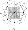
- FIG. 4 shows a similar ASG to the one in Figure 3 in circular source geometry for an imager IA having fifteen X-ray sources sl-sl5.
- six additional sources have been added (shown as light dots), two onto the source line sl5 of center grid M5 and to either side of center source M5, and four other sources have been placed, respectively, on the four source lines sl1-sl4.
- the envelope of the source positions in plan view is circular around the optical axis.
- the source line of the center grid M5 runs parallel to a longitudinal axis of the patient support, whilst in other embodiments the center grid source line runs across.
- This later arrangement is obtained by rotation of the ASG in Figs 3 , 4 and 5 by 90° clockwise or anti-clockwise.
- central grid M5 is symmetric whilst the remaining ones are antisymmetric.
- the above is not confined to 90° rotations, as embodiments of the ASG obtainable by rotations any other than by 90° are also envisaged herein.
- FIG. 5 showing another source geometry, but now in elliptic layout with nine sources s1-s9 in Figure 5A whilst in Figure 5B there are fifteen sources s1-s15 used.
- the ASG is similar to the one described above with 4 peripheral grids M1-M4 and one center grid M5 for AP view imaging.
- the shape of ASG in Figure 5A is planar rectangular, whilst the one in Fig 5B is planar square.
- the bj indicates as before the respective area of the sub-grids irradiated by source sj.
- b5 indicates the area of the center grid irradiated by source s5 situated below or above the ASG whilst rectangle b7 indicates the area irradiated by source S7 and filtered by S8.
- Fig 5B The source geometry in Fig 5B is obtained from the one in Fig 5A by adding 6 additional sources, two on the source line of the center grid to either side of the main optical axis Z and 4 other sources (shown as larger dots) placed on the four respective source lines between pairs of source lines of Fig 5A . Adding more sources on given source line, that is, to more densely populate a given source line with more sources allows extraction of more tomographic information which may be helpful in bone removal image processing.
- FIG. 5 B This is illustrated in Fig 5 B) , eg for a main view from an additional source sx added on the common source line sl2 in between sources s12 and s7.
- Figure 6 As a variant of the planar ASG grids as described above, reference is now made to Figure 6 where a curved embodiment is shown.
- This curved ASG is similar to the ones discussed before otherwise to the ones before including a center grid and four outer grids M1-M4.
- the curved ASG grid is configured for use with detectors having a correspondingly curved surface.
- Figure 6A shows the curved construction versus a planar construction and illustrates the more compact built achievable as indicated by arrow L.
- the curved grid is shown in plan view (top) and in side elevation in X, Z plane (bottom) whilst in use in the imager IA.
- Figure 6C shows a plan view versus a perspective view of the curved grid as proposed herein, according to one embodiment.
- it is only the center grid M5 that is curved whilst the peripheral grids M1-M4 are planar as before.
- the peripheral sub-grids M1-M4 are joined to the curved center grids at its straight pair of edges in tangential extension thereof (see bottom of Fig 6C ).
- Two sub-grids with different source line orientations are added to each side, with opposing pairs across the center grid having the same source line orientations similar to the previous embodiments Fig 3-5 .
- the center grid M5 is obtained using an initially flat sub-grid with only non-angulated strips and this is then bent about an axis parallel to its strips to achieve a symmetrical angulation throughout the strips.
- the curved composite grid ASG constructed from a mix of curved and planar modules
- other, "pure" embodiments are also envisaged where the ASG is curved through-out so is made up from curved modules only.
- Pane 6B illustrates the manufactural advantage conferred by having a curved center sub-grid between planar sub-grids.
- the maximum inclination angle in the planar sub-grids can be reduced because the curvature of the center grid adds an additional angulation component.
- the inclinations/angulations grow proportionally towards the outer portion in each sub-grid with the outermost strip having the strongest inclination. The inclination of the outermost strip is called the maximum inclination for the grid. Having a curved grid then allows increasing this maximum angle which is easier to produce.
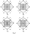
- Figure 7A shows a planar ASG as envisaged herein as having four sub-grids M1-M4 arranged as 4 quadrants around a center. There is no center grid as before. The grid defines four source lines that intersect to form quadrangular, such as a rectangle, or, specifically in this case, a square.
- Figures 7B-7D show different irradiation areas bj as produced by the corresponding sources sj. Sources s8 and s2 and sources s6 and s4 are positioned on source line intersections and hence their respective beams use different portions from different sub-grids for joint filtering.
- source s8 irradiates sub-grid M2 and M3 whilst source s2 irradiates grids M1,M4 and so on.
- sources s1, s3, s9 and s7 There is no grid sharing for sources s1, s3, s9 and s7 as shown in Figure 7B .
- the irradiated areas b1,b7,b9 and b3 are coextensive with the irradiated sub-grid areas but this is not necessarily so in all embodiments as shown in Fig 5B for instance, where the irradiated area b12 of source s12 is smaller than the total area of sub-grid M2, even in a non-grid sharing irradiation.
- Fig 8 is a plan view from top along central axis Z on an ASG with a source configuration comprising 8 sources s1-s8 (indicated as sj in the Fig 8 ). These are arranged in two squares, with two sets of 4 sources each defining the respective vertices of the two squares. The two square sub-configurations are rotated relative to each other by about 10°-15°around axis Z to obtain the configuration shown in Fig 8 . Variants of the above are also envisaged, such as configurations made up from more than two squares and/or where two or more squares are rotated by any other angle relative to each other.
- the polygons are regular (eg, as above square, or isosceles triangles, etc) to achieve at least quasi-isotropic source geometry for the reasons explained above.
- Figs 3-7 , 8 if the ASG is planar (ie, all modules lie in a common plane), not all modules are symmetric. There is at least one (such as four as in the above embodiments) asymmetric grid(s). However there are other embodiments envisaged that are at least partly curved, where all sub-grids Mj are symmetric. This allows achieving a very compact imager footprint. This may be advantageous for mobile (eg, wheeled) X-ray imagers.
- the manufacturing of the ASG as proposed herein requires in general a specification of the imaging geometry of the imager in which it is to be used.
- the dimensions of the imager or its footprint must be known.
- the general layout of the peripheral X-ray sources must be known and also whether an AP view is required.
- the position of the detector relative to the X-ray sources has to be known.
- the required source lines can be computed and these can then be used to manufacture the sub-grids. From the location of the source line in 3D the required inclination angles, in particular the maximum inclination angle of the strips, can be computed.
- the strip is constructed as a monolithic structure, with the strips in the different module being part of one continuous super-strip that is bent, and angulated to lay out the required pattern.
- This shape is the filled with filler material to obtain the finished ASG.
- a number of strips are formed into a series of nested polygonal shapes of progressively growing size.
- the grid is manufactured from the desired number of sub-grids each being produced separately by a series of strips angled as required and separated by the filler material.
- the sub-grids so fashioned are then joined (glued, etc) at their edges to form the composite ASG.
- the ASG is an assembly of sub-grids.
- sub-grids are so joined that there is no gap between neighboring strips from different sets and it is preferable to connect these by soldering etc to avoid passage of unfiltered radiation therethrough.
- One way to produce a sub-grid is to use a planar working plate with a raised shoulder at one of its edges.
- the x-radiation-opaque strips STj are then stacked up against this shoulder in alternate fashion with buffer strips to so build up the sub-grid.
- Glue is interposed at the buffer strip/ x-radiation-opaque strip-interface to glue this system of strips together.
- Strip-stack is then released from the working plate, cut (if need be) into the desired size to so obtain the ASG grid module Mj.
- the filler strips must be cut with a cutting tool at suitable angles to produce angled faces to which the x-radiation-opaque strips STj are then applied to so effect the angulation of the strips.
- a glue layer of sufficient thickness and pliability is applied to join the filler strips and the x-radiation-opaque strips and it is this glue layer that then accommodates the slight angulation of strips with respect to their immediate neighboring strips.
Landscapes
- Health & Medical Sciences (AREA)
- Life Sciences & Earth Sciences (AREA)
- Medical Informatics (AREA)
- Engineering & Computer Science (AREA)
- Radiology & Medical Imaging (AREA)
- Biomedical Technology (AREA)
- Biophysics (AREA)
- Nuclear Medicine, Radiotherapy & Molecular Imaging (AREA)
- Optics & Photonics (AREA)
- Pathology (AREA)
- Physics & Mathematics (AREA)
- High Energy & Nuclear Physics (AREA)
- Heart & Thoracic Surgery (AREA)
- Molecular Biology (AREA)
- Surgery (AREA)
- Animal Behavior & Ethology (AREA)
- General Health & Medical Sciences (AREA)
- Public Health (AREA)
- Veterinary Medicine (AREA)
- Apparatus For Radiation Diagnosis (AREA)
Claims (14)
- Appareil d'imagerie à rayons X (IA) comprenant une grille anti-diffusion (ASG) pour une imagerie à rayons X comprenant au moins deux ensembles (Mj) de bandes opaques à rayons X linéaires (STj), chacune des bandes dans les au moins deux ensembles présentant un axe longitudinal respectif (Li), dans lequel il existe au moins deux bandes de différents ensembles parmi les au moins deux ensembles qui ont des axes longitudinaux non parallèles, caractérisé en ce que l'appareil d'imagerie à rayons X (IA) a une pluralité de sources de rayons X (sj).
- Appareil d'imagerie à rayons X selon la revendication 1, dans lequel au moins une bande (STj) de l'un des au moins deux ensembles (Mj) est inclinée autour de ses axes longitudinaux par rapport à une autre bande dudit un des au moins deux ensembles.
- Appareil d'imagerie à rayons X selon la revendication 1 ou 2, dans lequel les bandes dans au moins l'un des au moins deux ensembles forment un plan.
- Appareil d'imagerie à rayons X selon l'une quelconque des revendications précédentes, dans lequel les bandes dans au moins l'un des au moins deux ensembles forment une surface incurvée.
- Appareil d'imagerie à rayons X selon l'une quelconque des revendications 1 à 3, dans lequel les au moins deux ensembles sont agencés dans un plan commun.
- Appareil d'imagerie à rayons X selon l'une quelconque des revendications précédentes présentant au moins n ≥ 3 de ces ensembles, dans lequel les axes longitudinaux respectifs (Lj) de n bandes d'ensembles différents des au moins n ensembles (Mj) forment un polygone avec n sommets.
- Appareil d'imagerie à rayons X selon l'une quelconque des revendications précédentes, dans lequel la grille anti-diffusion (ASG) est agencée à l'avant d'un détecteur de rayons X de l'appareil d'imagerie (IA).
- Appareil d'imagerie à rayons X (IA) selon l'une quelconque des revendications précédentes, dans lequel il existe au moins trois sources de rayons X (sj) configurées pour émettre des faisceaux de rayons X respectifs (Bj) vers le détecteur, dans lequel les sources de rayons X (sj) sont agencées autour d'un axe optique du détecteur (D).
- Appareil d'imagerie à rayons X (IA) selon la revendication 8, dans lequel les au moins trois sources de rayons X peuvent être positionnées sur un plan qui ne croise pas le détecteur (D).
- Appareil d'imagerie à rayons X (IA) selon l'une quelconque des revendications précédentes, dans lequel la grille anti-diffusion (ASG) est configurée pour effectuer un filtrage directionnel par rapport à l'un quelconque des faisceaux de rayons X (Bj).
- Appareil d'imagerie à rayons X (IA) selon l'une quelconque des revendications précédentes, dans lequel au moins l'un des faisceaux irradie, en même temps, des bandes (STj) d'ensembles différents des au moins deux ensembles (Mj).
- Appareil d'imagerie à rayons X (IA) selon l'une quelconque des revendications 2 à 11, dans lequel les bandes (STi) sont inclinées les unes par rapport aux autres de façon à focaliser la grille anti-diffusion (ASG) vers une ligne (slj) passant à travers un point focal (FSj) d'au moins l'une des sources de rayons X (sj) de l'appareil d'imagerie (IA).
- Appareil d'imagerie à rayons X (IA) selon l'une quelconque des revendications précédentes, dans lequel des bandes (STi) de différents ensembles des au moins deux ensembles (Mj) sont focalisées vers des lignes différentes (slj) passant à travers les points focaux de différentes sources de rayons X de la pluralité de sources de rayons X (sj).
- Appareil d'imagerie à rayons X (IA) selon la revendication 12, dans lequel des bandes (STi) de différents ensembles des au moins deux ensembles (Mj) sont focalisées vers des lignes différentes (slj) qui se croisent au niveau du point focal (FSj).
Applications Claiming Priority (2)
| Application Number | Priority Date | Filing Date | Title |
|---|---|---|---|
| EP16172577 | 2016-06-02 | ||
| PCT/EP2017/063396 WO2017207734A1 (fr) | 2016-06-02 | 2017-06-01 | Appareil d'imagerie par rayons x pour imagerie par rayons x compacte (quasi-) isotrope à source multiple |
Publications (2)
| Publication Number | Publication Date |
|---|---|
| EP3463090A1 EP3463090A1 (fr) | 2019-04-10 |
| EP3463090B1 true EP3463090B1 (fr) | 2020-01-01 |
Family
ID=56098100
Family Applications (1)
| Application Number | Title | Priority Date | Filing Date |
|---|---|---|---|
| EP17727868.6A Active EP3463090B1 (fr) | 2016-06-02 | 2017-06-01 | Grille d'anti-diffusion pour imagerie à rayons x à source multiples (quasi)-isotrope compacte |
Country Status (5)
| Country | Link |
|---|---|
| US (1) | US11058375B2 (fr) |
| EP (1) | EP3463090B1 (fr) |
| JP (1) | JP7025352B2 (fr) |
| CN (1) | CN109195525B (fr) |
| WO (1) | WO2017207734A1 (fr) |
Cited By (1)
| Publication number | Priority date | Publication date | Assignee | Title |
|---|---|---|---|---|
| US11051771B2 (en) | 2014-06-17 | 2021-07-06 | Xintek, Inc. | Stationary intraoral tomosynthesis imaging systems, methods, and computer readable media for three dimensional dental imaging |
Families Citing this family (4)
| Publication number | Priority date | Publication date | Assignee | Title |
|---|---|---|---|---|
| KR101164490B1 (ko) | 2012-04-25 | 2012-07-18 | 주식회사 드림앤첼린지 | 자전거 변속장치 |
| EP3498171A1 (fr) * | 2017-12-15 | 2019-06-19 | Koninklijke Philips N.V. | Imagerie à contraste de phase à rayon x de tir unique et à champ sombre |
| CN111657979A (zh) * | 2019-03-08 | 2020-09-15 | 江苏一影医疗设备有限公司 | Ct成像系统及其成像方法 |
| US11771387B2 (en) * | 2020-01-29 | 2023-10-03 | Aixscan Inc. | Fast 3D radiography using multiple pulsed X-ray sources in motion |
Family Cites Families (26)
| Publication number | Priority date | Publication date | Assignee | Title |
|---|---|---|---|---|
| DE545048C (de) * | 1927-04-20 | 1932-02-24 | Gaiffe Gallot Et Pilon Sa Ets | Blende fuer Roentgenapparate |
| JP3730319B2 (ja) | 1996-06-21 | 2006-01-05 | 株式会社東芝 | X線コンピュータ断層撮影装置 |
| GB9904692D0 (en) * | 1999-03-01 | 1999-04-21 | Isis Innovation | X-ray image processing |
| US6222904B1 (en) * | 1999-07-22 | 2001-04-24 | Canon Kabushiki Kaisha | Stereo x-ray anti-scatter grid |
| US6438210B1 (en) * | 2000-03-28 | 2002-08-20 | General Electric Company | Anti-scatter grid, method, and apparatus for forming same |
| US6470072B1 (en) * | 2000-08-24 | 2002-10-22 | General Electric Company | X-ray anti-scatter grid |
| WO2002065480A1 (fr) * | 2001-02-01 | 2002-08-22 | Creatv Microtech, Inc. | Modeles de collimateurs et de grilles antidiffusion, et leur deplacement, fabrication et assemblage |
| DE10136946A1 (de) | 2001-07-28 | 2003-02-06 | Philips Corp Intellectual Pty | Streustrahlenraster für eine Röntgeneinrichtung |
| US20090323899A1 (en) | 2005-09-19 | 2009-12-31 | Koninklijke Philips Electronics N. V. | Grid for selective absorption of electromagnetic radiation and method for its manufacture |
| CN101689464A (zh) * | 2007-07-11 | 2010-03-31 | 皇家飞利浦电子股份有限公司 | 用于测量辐射的x射线源 |
| WO2009012453A1 (fr) * | 2007-07-19 | 2009-01-22 | The University Of North Carolina At Chapel Hill | Systèmes de tomosynthèse numérique du sein aux rayons x stationnaires et procédés apparentés |
| ATE535190T1 (de) * | 2007-10-01 | 2011-12-15 | Koninkl Philips Electronics Nv | Computertomographiegerät |
| DE102007058986B3 (de) * | 2007-12-07 | 2009-07-30 | Siemens Ag | Streustrahlenraster und Verfahren zur Herstellung |
| US20100246753A1 (en) | 2009-03-25 | 2010-09-30 | Varian Medical Systems, Inc. | Fourth Generation Computed Tomography Scanner |
| JP5460106B2 (ja) * | 2009-04-03 | 2014-04-02 | キヤノン株式会社 | X線撮影装置及びその制御方法、コンピュータプログラム |
| WO2010133920A1 (fr) * | 2009-05-20 | 2010-11-25 | Koninklijke Philips Electronics N.V. | Agencement anti-diffusion pour détecteur de radiations |
| FR2953320B1 (fr) | 2009-11-27 | 2013-07-05 | Gen Electric | Grille anti-diffusante inversee |
| JP5586986B2 (ja) * | 2010-02-23 | 2014-09-10 | キヤノン株式会社 | X線撮像装置 |
| US9048002B2 (en) | 2010-10-08 | 2015-06-02 | Turtle Bay Partners, Llc | Three-dimensional focused anti-scatter grid and method for manufacturing thereof |
| JP6228457B2 (ja) * | 2010-10-19 | 2017-11-08 | コーニンクレッカ フィリップス エヌ ヴェKoninklijke Philips N.V. | 微分位相コントラスト画像形成 |
| JP2012130586A (ja) * | 2010-12-22 | 2012-07-12 | Fujifilm Corp | 放射線画像検出装置、放射線撮影装置、及び放射線撮影システム |
| US9901315B2 (en) * | 2013-03-15 | 2018-02-27 | Hologic, Inc. | X-ray scatter reducing device for use with 2D mammography and tomosynthesis |
| US20170206996A1 (en) * | 2014-07-23 | 2017-07-20 | Turtle Bay Partners,LLC | Practical method for fabricating foam interspaced anti-scatter grid and improved grids |
| EP3420722B1 (fr) | 2016-02-23 | 2022-04-13 | Koninklijke Philips N.V. | Appareil d'imagerie à rayons x avec compensation de rayonnement à diffusion croisée par commande du détecteur à rayons x |
| US10062466B2 (en) * | 2016-03-31 | 2018-08-28 | General Electric Company | Apparatus, system and method for reducing radiation scatter in an imaging system |
| CN109310384B (zh) | 2016-05-13 | 2023-07-04 | 皇家飞利浦有限公司 | 用于4d成像的多射束x射线暴露的系统和方法 |
-
2017
- 2017-06-01 WO PCT/EP2017/063396 patent/WO2017207734A1/fr unknown
- 2017-06-01 JP JP2018563125A patent/JP7025352B2/ja active Active
- 2017-06-01 US US16/305,904 patent/US11058375B2/en active Active
- 2017-06-01 CN CN201780033259.8A patent/CN109195525B/zh active Active
- 2017-06-01 EP EP17727868.6A patent/EP3463090B1/fr active Active
Non-Patent Citations (1)
| Title |
|---|
| None * |
Cited By (1)
| Publication number | Priority date | Publication date | Assignee | Title |
|---|---|---|---|---|
| US11051771B2 (en) | 2014-06-17 | 2021-07-06 | Xintek, Inc. | Stationary intraoral tomosynthesis imaging systems, methods, and computer readable media for three dimensional dental imaging |
Also Published As
| Publication number | Publication date |
|---|---|
| US20200315559A1 (en) | 2020-10-08 |
| JP7025352B2 (ja) | 2022-02-24 |
| CN109195525B (zh) | 2023-09-08 |
| EP3463090A1 (fr) | 2019-04-10 |
| US11058375B2 (en) | 2021-07-13 |
| CN109195525A (zh) | 2019-01-11 |
| WO2017207734A1 (fr) | 2017-12-07 |
| JP2019517320A (ja) | 2019-06-24 |
Similar Documents
| Publication | Publication Date | Title |
|---|---|---|
| EP3463090B1 (fr) | Grille d'anti-diffusion pour imagerie à rayons x à source multiples (quasi)-isotrope compacte | |
| JP6488292B2 (ja) | トモシンセシスシステムのようなx線システム及び対象の画像を取得する方法 | |
| JP2005537846A (ja) | Ctスキャナ用の散乱防止x線遮蔽 | |
| EP2948061B1 (fr) | Champs de rayons x dirigés pour tomosynthèse | |
| JP6548219B2 (ja) | Ct検出器 | |
| JP7097819B2 (ja) | 4dイメージングのためのマルチビームx線露光のためのシステム及び方法 | |
| US8976935B2 (en) | Collimator grid and an associated method of fabrication | |
| JP2000325332A (ja) | イメージング・システム用のコリメータ装置およびその製作方法 | |
| US20130235972A1 (en) | Method for manufacturing collimator, collimator and x-ray ct apparatus | |
| US9730652B2 (en) | Device and method for radiographic and nuclear imaging of an object | |
| US8290121B2 (en) | Method for producing a comb-like collimator element for a collimator arrangement and collimator element | |
| JP2008173233A (ja) | 断層撮影装置 | |
| JP2008145335A (ja) | シンチレータアレイ製造方法、シンチレータアレイ、x線検出器およびx線ct装置 | |
| KR20170082525A (ko) | 컴퓨터 단층 촬영 장치 및 연관된 방법 | |
| JP6395703B2 (ja) | 放射線検出器とそれを備えたx線ct装置 | |
| CN111386077B (zh) | 一种x射线成像设备 | |
| JP7171561B2 (ja) | 格子ベースの位相コントラスト画像化 | |
| JP7442458B2 (ja) | 均一なイメージングのための集束型シンチレータ構造のx線検出器 | |
| JP5272943B2 (ja) | 放射線撮影装置 | |
| WO2017094294A1 (fr) | Appareil photographique de talbot à rayons x | |
| JP2012157690A (ja) | 放射線画像撮影装置および放射線画像検出器 | |
| JP6696296B2 (ja) | タルボ撮影装置 | |
| JP5943760B2 (ja) | 放射線検出装置および放射線撮影装置 | |
| JP2018189933A (ja) | 格子及びx線タルボ撮影装置、格子の製造方法 |
Legal Events
| Date | Code | Title | Description |
|---|---|---|---|
| STAA | Information on the status of an ep patent application or granted ep patent |
Free format text: STATUS: UNKNOWN |
|
| STAA | Information on the status of an ep patent application or granted ep patent |
Free format text: STATUS: THE INTERNATIONAL PUBLICATION HAS BEEN MADE |
|
| PUAI | Public reference made under article 153(3) epc to a published international application that has entered the european phase |
Free format text: ORIGINAL CODE: 0009012 |
|
| STAA | Information on the status of an ep patent application or granted ep patent |
Free format text: STATUS: REQUEST FOR EXAMINATION WAS MADE |
|
| 17P | Request for examination filed |
Effective date: 20190102 |
|
| AK | Designated contracting states |
Kind code of ref document: A1 Designated state(s): AL AT BE BG CH CY CZ DE DK EE ES FI FR GB GR HR HU IE IS IT LI LT LU LV MC MK MT NL NO PL PT RO RS SE SI SK SM TR |
|
| AX | Request for extension of the european patent |
Extension state: BA ME |
|
| GRAP | Despatch of communication of intention to grant a patent |
Free format text: ORIGINAL CODE: EPIDOSNIGR1 |
|
| STAA | Information on the status of an ep patent application or granted ep patent |
Free format text: STATUS: GRANT OF PATENT IS INTENDED |
|
| INTG | Intention to grant announced |
Effective date: 20190729 |
|
| DAV | Request for validation of the european patent (deleted) | ||
| DAX | Request for extension of the european patent (deleted) | ||
| GRAS | Grant fee paid |
Free format text: ORIGINAL CODE: EPIDOSNIGR3 |
|
| GRAA | (expected) grant |
Free format text: ORIGINAL CODE: 0009210 |
|
| STAA | Information on the status of an ep patent application or granted ep patent |
Free format text: STATUS: THE PATENT HAS BEEN GRANTED |
|
| AK | Designated contracting states |
Kind code of ref document: B1 Designated state(s): AL AT BE BG CH CY CZ DE DK EE ES FI FR GB GR HR HU IE IS IT LI LT LU LV MC MK MT NL NO PL PT RO RS SE SI SK SM TR |
|
| REG | Reference to a national code |
Ref country code: GB Ref legal event code: FG4D |
|
| REG | Reference to a national code |
Ref country code: CH Ref legal event code: EP Ref country code: AT Ref legal event code: REF Ref document number: 1218775 Country of ref document: AT Kind code of ref document: T Effective date: 20200115 |
|
| REG | Reference to a national code |
Ref country code: IE Ref legal event code: FG4D |
|
| REG | Reference to a national code |
Ref country code: DE Ref legal event code: R096 Ref document number: 602017010458 Country of ref document: DE |
|
| RAP2 | Party data changed (patent owner data changed or rights of a patent transferred) |
Owner name: KONINKLIJKE PHILIPS N.V. |
|
| REG | Reference to a national code |
Ref country code: NL Ref legal event code: MP Effective date: 20200101 |
|
| REG | Reference to a national code |
Ref country code: LT Ref legal event code: MG4D |
|
| PG25 | Lapsed in a contracting state [announced via postgrant information from national office to epo] |
Ref country code: NL Free format text: LAPSE BECAUSE OF FAILURE TO SUBMIT A TRANSLATION OF THE DESCRIPTION OR TO PAY THE FEE WITHIN THE PRESCRIBED TIME-LIMIT Effective date: 20200101 Ref country code: LT Free format text: LAPSE BECAUSE OF FAILURE TO SUBMIT A TRANSLATION OF THE DESCRIPTION OR TO PAY THE FEE WITHIN THE PRESCRIBED TIME-LIMIT Effective date: 20200101 Ref country code: RS Free format text: LAPSE BECAUSE OF FAILURE TO SUBMIT A TRANSLATION OF THE DESCRIPTION OR TO PAY THE FEE WITHIN THE PRESCRIBED TIME-LIMIT Effective date: 20200101 Ref country code: CZ Free format text: LAPSE BECAUSE OF FAILURE TO SUBMIT A TRANSLATION OF THE DESCRIPTION OR TO PAY THE FEE WITHIN THE PRESCRIBED TIME-LIMIT Effective date: 20200101 Ref country code: PT Free format text: LAPSE BECAUSE OF FAILURE TO SUBMIT A TRANSLATION OF THE DESCRIPTION OR TO PAY THE FEE WITHIN THE PRESCRIBED TIME-LIMIT Effective date: 20200527 Ref country code: FI Free format text: LAPSE BECAUSE OF FAILURE TO SUBMIT A TRANSLATION OF THE DESCRIPTION OR TO PAY THE FEE WITHIN THE PRESCRIBED TIME-LIMIT Effective date: 20200101 Ref country code: NO Free format text: LAPSE BECAUSE OF FAILURE TO SUBMIT A TRANSLATION OF THE DESCRIPTION OR TO PAY THE FEE WITHIN THE PRESCRIBED TIME-LIMIT Effective date: 20200401 |
|
| PG25 | Lapsed in a contracting state [announced via postgrant information from national office to epo] |
Ref country code: BG Free format text: LAPSE BECAUSE OF FAILURE TO SUBMIT A TRANSLATION OF THE DESCRIPTION OR TO PAY THE FEE WITHIN THE PRESCRIBED TIME-LIMIT Effective date: 20200401 Ref country code: GR Free format text: LAPSE BECAUSE OF FAILURE TO SUBMIT A TRANSLATION OF THE DESCRIPTION OR TO PAY THE FEE WITHIN THE PRESCRIBED TIME-LIMIT Effective date: 20200402 Ref country code: HR Free format text: LAPSE BECAUSE OF FAILURE TO SUBMIT A TRANSLATION OF THE DESCRIPTION OR TO PAY THE FEE WITHIN THE PRESCRIBED TIME-LIMIT Effective date: 20200101 Ref country code: SE Free format text: LAPSE BECAUSE OF FAILURE TO SUBMIT A TRANSLATION OF THE DESCRIPTION OR TO PAY THE FEE WITHIN THE PRESCRIBED TIME-LIMIT Effective date: 20200101 Ref country code: LV Free format text: LAPSE BECAUSE OF FAILURE TO SUBMIT A TRANSLATION OF THE DESCRIPTION OR TO PAY THE FEE WITHIN THE PRESCRIBED TIME-LIMIT Effective date: 20200101 Ref country code: IS Free format text: LAPSE BECAUSE OF FAILURE TO SUBMIT A TRANSLATION OF THE DESCRIPTION OR TO PAY THE FEE WITHIN THE PRESCRIBED TIME-LIMIT Effective date: 20200501 |
|
| REG | Reference to a national code |
Ref country code: DE Ref legal event code: R097 Ref document number: 602017010458 Country of ref document: DE |
|
| PG25 | Lapsed in a contracting state [announced via postgrant information from national office to epo] |
Ref country code: SK Free format text: LAPSE BECAUSE OF FAILURE TO SUBMIT A TRANSLATION OF THE DESCRIPTION OR TO PAY THE FEE WITHIN THE PRESCRIBED TIME-LIMIT Effective date: 20200101 Ref country code: RO Free format text: LAPSE BECAUSE OF FAILURE TO SUBMIT A TRANSLATION OF THE DESCRIPTION OR TO PAY THE FEE WITHIN THE PRESCRIBED TIME-LIMIT Effective date: 20200101 Ref country code: DK Free format text: LAPSE BECAUSE OF FAILURE TO SUBMIT A TRANSLATION OF THE DESCRIPTION OR TO PAY THE FEE WITHIN THE PRESCRIBED TIME-LIMIT Effective date: 20200101 Ref country code: SM Free format text: LAPSE BECAUSE OF FAILURE TO SUBMIT A TRANSLATION OF THE DESCRIPTION OR TO PAY THE FEE WITHIN THE PRESCRIBED TIME-LIMIT Effective date: 20200101 Ref country code: EE Free format text: LAPSE BECAUSE OF FAILURE TO SUBMIT A TRANSLATION OF THE DESCRIPTION OR TO PAY THE FEE WITHIN THE PRESCRIBED TIME-LIMIT Effective date: 20200101 Ref country code: ES Free format text: LAPSE BECAUSE OF FAILURE TO SUBMIT A TRANSLATION OF THE DESCRIPTION OR TO PAY THE FEE WITHIN THE PRESCRIBED TIME-LIMIT Effective date: 20200101 |
|
| PLBE | No opposition filed within time limit |
Free format text: ORIGINAL CODE: 0009261 |
|
| STAA | Information on the status of an ep patent application or granted ep patent |
Free format text: STATUS: NO OPPOSITION FILED WITHIN TIME LIMIT |
|
| REG | Reference to a national code |
Ref country code: AT Ref legal event code: MK05 Ref document number: 1218775 Country of ref document: AT Kind code of ref document: T Effective date: 20200101 |
|
| 26N | No opposition filed |
Effective date: 20201002 |
|
| PG25 | Lapsed in a contracting state [announced via postgrant information from national office to epo] |
Ref country code: MC Free format text: LAPSE BECAUSE OF FAILURE TO SUBMIT A TRANSLATION OF THE DESCRIPTION OR TO PAY THE FEE WITHIN THE PRESCRIBED TIME-LIMIT Effective date: 20200101 Ref country code: IT Free format text: LAPSE BECAUSE OF FAILURE TO SUBMIT A TRANSLATION OF THE DESCRIPTION OR TO PAY THE FEE WITHIN THE PRESCRIBED TIME-LIMIT Effective date: 20200101 Ref country code: AT Free format text: LAPSE BECAUSE OF FAILURE TO SUBMIT A TRANSLATION OF THE DESCRIPTION OR TO PAY THE FEE WITHIN THE PRESCRIBED TIME-LIMIT Effective date: 20200101 |
|
| REG | Reference to a national code |
Ref country code: CH Ref legal event code: PL |
|
| PG25 | Lapsed in a contracting state [announced via postgrant information from national office to epo] |
Ref country code: SI Free format text: LAPSE BECAUSE OF FAILURE TO SUBMIT A TRANSLATION OF THE DESCRIPTION OR TO PAY THE FEE WITHIN THE PRESCRIBED TIME-LIMIT Effective date: 20200101 Ref country code: PL Free format text: LAPSE BECAUSE OF FAILURE TO SUBMIT A TRANSLATION OF THE DESCRIPTION OR TO PAY THE FEE WITHIN THE PRESCRIBED TIME-LIMIT Effective date: 20200101 |
|
| PG25 | Lapsed in a contracting state [announced via postgrant information from national office to epo] |
Ref country code: LU Free format text: LAPSE BECAUSE OF NON-PAYMENT OF DUE FEES Effective date: 20200601 |
|
| REG | Reference to a national code |
Ref country code: BE Ref legal event code: MM Effective date: 20200630 |
|
| PG25 | Lapsed in a contracting state [announced via postgrant information from national office to epo] |
Ref country code: CH Free format text: LAPSE BECAUSE OF NON-PAYMENT OF DUE FEES Effective date: 20200630 Ref country code: LI Free format text: LAPSE BECAUSE OF NON-PAYMENT OF DUE FEES Effective date: 20200630 Ref country code: IE Free format text: LAPSE BECAUSE OF NON-PAYMENT OF DUE FEES Effective date: 20200601 |
|
| PG25 | Lapsed in a contracting state [announced via postgrant information from national office to epo] |
Ref country code: BE Free format text: LAPSE BECAUSE OF NON-PAYMENT OF DUE FEES Effective date: 20200630 |
|
| GBPC | Gb: european patent ceased through non-payment of renewal fee |
Effective date: 20210601 |
|
| PG25 | Lapsed in a contracting state [announced via postgrant information from national office to epo] |
Ref country code: GB Free format text: LAPSE BECAUSE OF NON-PAYMENT OF DUE FEES Effective date: 20210601 |
|
| PG25 | Lapsed in a contracting state [announced via postgrant information from national office to epo] |
Ref country code: TR Free format text: LAPSE BECAUSE OF FAILURE TO SUBMIT A TRANSLATION OF THE DESCRIPTION OR TO PAY THE FEE WITHIN THE PRESCRIBED TIME-LIMIT Effective date: 20200101 Ref country code: MT Free format text: LAPSE BECAUSE OF FAILURE TO SUBMIT A TRANSLATION OF THE DESCRIPTION OR TO PAY THE FEE WITHIN THE PRESCRIBED TIME-LIMIT Effective date: 20200101 Ref country code: CY Free format text: LAPSE BECAUSE OF FAILURE TO SUBMIT A TRANSLATION OF THE DESCRIPTION OR TO PAY THE FEE WITHIN THE PRESCRIBED TIME-LIMIT Effective date: 20200101 |
|
| PG25 | Lapsed in a contracting state [announced via postgrant information from national office to epo] |
Ref country code: MK Free format text: LAPSE BECAUSE OF FAILURE TO SUBMIT A TRANSLATION OF THE DESCRIPTION OR TO PAY THE FEE WITHIN THE PRESCRIBED TIME-LIMIT Effective date: 20200101 Ref country code: AL Free format text: LAPSE BECAUSE OF FAILURE TO SUBMIT A TRANSLATION OF THE DESCRIPTION OR TO PAY THE FEE WITHIN THE PRESCRIBED TIME-LIMIT Effective date: 20200101 |
|
| PGFP | Annual fee paid to national office [announced via postgrant information from national office to epo] |
Ref country code: FR Payment date: 20220623 Year of fee payment: 6 |
|
| PGFP | Annual fee paid to national office [announced via postgrant information from national office to epo] |
Ref country code: DE Payment date: 20230627 Year of fee payment: 7 |
|
| REG | Reference to a national code |
Ref country code: DE Ref legal event code: R084 Ref document number: 602017010458 Country of ref document: DE |