EP3461982B1 - Türanordnung - Google Patents
Türanordnung Download PDFInfo
- Publication number
- EP3461982B1 EP3461982B1 EP18197458.5A EP18197458A EP3461982B1 EP 3461982 B1 EP3461982 B1 EP 3461982B1 EP 18197458 A EP18197458 A EP 18197458A EP 3461982 B1 EP3461982 B1 EP 3461982B1
- Authority
- EP
- European Patent Office
- Prior art keywords
- door
- frame
- door leaf
- door frame
- wall
- Prior art date
- Legal status (The legal status is an assumption and is not a legal conclusion. Google has not performed a legal analysis and makes no representation as to the accuracy of the status listed.)
- Active
Links
Images


Classifications
-
- E—FIXED CONSTRUCTIONS
- E06—DOORS, WINDOWS, SHUTTERS, OR ROLLER BLINDS IN GENERAL; LADDERS
- E06B—FIXED OR MOVABLE CLOSURES FOR OPENINGS IN BUILDINGS, VEHICLES, FENCES OR LIKE ENCLOSURES IN GENERAL, e.g. DOORS, WINDOWS, BLINDS, GATES
- E06B1/00—Border constructions of openings in walls, floors, or ceilings; Frames to be rigidly mounted in such openings
- E06B1/04—Frames for doors, windows, or the like to be fixed in openings
-
- E—FIXED CONSTRUCTIONS
- E05—LOCKS; KEYS; WINDOW OR DOOR FITTINGS; SAFES
- E05D—HINGES OR SUSPENSION DEVICES FOR DOORS, WINDOWS OR WINGS
- E05D3/00—Hinges with pins
- E05D3/06—Hinges with pins with two or more pins
- E05D3/18—Hinges with pins with two or more pins with sliding pins or guides
- E05D3/186—Scissors hinges, with two crossing levers and five parallel pins
-
- E—FIXED CONSTRUCTIONS
- E05—LOCKS; KEYS; WINDOW OR DOOR FITTINGS; SAFES
- E05D—HINGES OR SUSPENSION DEVICES FOR DOORS, WINDOWS OR WINGS
- E05D7/00—Hinges or pivots of special construction
- E05D7/08—Hinges or pivots of special construction for use in suspensions comprising two spigots placed at opposite edges of the wing, especially at the top and the bottom, e.g. trunnions
- E05D7/081—Hinges or pivots of special construction for use in suspensions comprising two spigots placed at opposite edges of the wing, especially at the top and the bottom, e.g. trunnions the pivot axis of the wing being situated near one edge of the wing, especially at the top and bottom, e.g. trunnions
-
- E—FIXED CONSTRUCTIONS
- E05—LOCKS; KEYS; WINDOW OR DOOR FITTINGS; SAFES
- E05Y—INDEXING SCHEME ASSOCIATED WITH SUBCLASSES E05D AND E05F, RELATING TO CONSTRUCTION ELEMENTS, ELECTRIC CONTROL, POWER SUPPLY, POWER SIGNAL OR TRANSMISSION, USER INTERFACES, MOUNTING OR COUPLING, DETAILS, ACCESSORIES, AUXILIARY OPERATIONS NOT OTHERWISE PROVIDED FOR, APPLICATION THEREOF
- E05Y2900/00—Application of doors, windows, wings or fittings thereof
- E05Y2900/50—Application of doors, windows, wings or fittings thereof for vehicles
- E05Y2900/53—Type of wing
- E05Y2900/531—Doors
Definitions
- the invention relates to a door arrangement with the features of the preamble of claim 1.
- a flush closure with the surrounding wall surface can be achieved by taking special structural and constructive measures ( DE 20 2015 005 011 U1 ).
- flush installation of the all-glass door leaf is possible both on the opposite hinge side, that is to say the door closing side, and on the hinge side, that is to say the door opening side of the all-glass door leaf.
- special structural measures must be taken.
- the door frame is one with clothing and lining. It can be designed as a surrounding frame or can also be designed such that the cladding is arranged flush with the wall surface of the wall surrounding the wall cutout. In any case, special structural measures on the wall cutout are required.
- Block frames are usually made of wood or metal, especially aluminum or stainless steel. Often an additional installation of a so-called substructure frame is required required. If this substructure frame is dispensed with, a deviation of just a few millimeters results in a visible defect or an uneven joint pattern.
- the present invention is therefore based on the problem of specifying a door arrangement of the type in question which can be mounted more expediently, in particular without further activities by the body-in-white trade.
- the depth of the door frame designed as a block frame is deliberately chosen to be less than the depth of the door leaf. It is further realized that the depth of the door frame on the frame rebate on the one hand and the depth of the door leaf on the door rebate on the other hand are matched to one another in such a way that the visible sides of the reveal part of the door frame lie behind the visible sides of the door leaf.
- the door frame is installed in the wall cutout of a wall opposite the wall surface of the wall. It can be attached to the inside of the completely plastered wall, including the wall cut-out. This is a pure work of the interior fittings trade.
- the door leaf lies with its visible sides on both sides in front of the visible sides of the door frame, which gives the overall arrangement a certain lightness, although the door leaf itself conveys a high value due to its considerable depth.
- the door arrangement according to the invention ensures that there is no visual relationship between the wall surface and the door frame.
- the door leaf has a very noble look, similar to a floating door leaf in an opening with an all-round shadow gap.
- the door arrangement according to the invention results in a very special flexibility.
- the door arrangement can be mounted in any wall cutout, only height and width need to be taken into account in the manufacturing process. No other special adjustments to the respective wall cutout need to be made.
- the opening direction of the door leaf and the position of the door arrangement need not be known or not taken into account during manufacture.
- the door arrangement can be installed flush with the wall surface as well as behind or protruding from the wall surface.
- the door frame can be at any depth of the wall section, for. B. in the middle. It is even possible to mount the door arrangement according to the invention between two walls or two wall surfaces.
- a door leaf made of wood can be used particularly expediently. If you want to use an all-glass door leaf, this is possible in principle, but requires additional design measures due to various fittings to be adapted.
- the door arrangement according to the invention can be used both in a new building and in an old building.
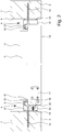
- Fig. 1 shows first of all the basic arrangement of a door in a wall 1.
- the wall 1 which forms a wall surface 2 on the front visible side, sits in a wall opening 3 a three-sided door frame 4.
- These three sides on which the door frame 4 rotates are the left vertical side, the right vertical side and the top transverse side.
- a door leaf 5 is inserted in the door frame 4.
- the view side of the door frame 4 is not arranged flush with the wall surface 2 of the wall 1, but is slightly in front of it. Basically, however, the view side of the door frame 4 can be arranged exactly flush with the wall surface 2 of the wall 1 by forming a corresponding flat recess in the wall 1.
- Door leaf 5 shown is made of wood. In principle, of course, an all-glass door leaf could also be used there.
- the door frame 4 is designed as a block frame and has a reveal part 8 fastened to the wall 1 and a frame rebate 9 projecting from the reveal part 8.
- a typical damping profile 10 made of an elastomer material, for example plastic, rubber or a mixture thereof, is shown on the frame rebate 9.
- a door rebate 11 is also formed on the door leaf 5. The surfaces of the frame rebate 9 and door rebate 11 come into contact with one another when the door leaf 5 is closed, here, of course, with the cooperation of the damping profile 10.
- the representation in Fig. 2 shows the essential essence of the teaching of this invention.
- the depth of the door frame 4 is less than the depth of the door leaf 5.
- the door leaf 5 is made of wood. This allows a particularly expedient attachment of the door leaf 5 in the door frame 4.
- the use of an all-glass door leaf at this point requires additional fittings, so it causes a greater design effort.
- the construction shown gives the overall arrangement an elegant style.
- the wall 1 finished with a coat of paint, including the plaster and possibly even the painter's trade.
- the door frame 4 can then be installed in the wall cutout 3 by the interior fitting trade. This is shown in the illustrated embodiment by the fastening screws 14 inserted into the masonry of the wall 1. From the assembly process of Viewed from the door arrangement according to the invention, this is a very useful fact.
- the visible sides 12 of the reveal part 8 of the door frame 4 lie on both sides by the same amount compared to the visible sides 13 of the door leaf 5.
- the door arrangement therefore has a similar appearance from both sides with regard to the recess.
- the door leaf 5 preferably has a depth of approximately 60 mm to 70 mm and the door frame 4 has a depth of approximately 40 mm to 50 mm. This gives the impression of a high quality interior.
- the door frame 4 For the door frame 4 realized according to the invention, it is recommended that the door frame 4 consist of metal, in particular aluminum or stainless steel.
- the construction according to the invention makes it seem expedient to use aluminum or stainless steel for the door frame 4 in particular.
- wood could of course also be used as the material for the door frame 4.
- wood Depending on the dimensions of the door frame 4, it can be structurally difficult with wood for reasons of strength. This has to be decided in each individual case on the basis of the constructive specifications on site.
- the door frame 4 is attached in the wall cutout 3 via supporting and sealing elements 15, for example in the form of a circumferential sealing tape.
- supporting and sealing elements 15 for example in the form of a circumferential sealing tape.
- An on-site connection with acrylic or silicone is also possible.
- FIG. 2 the drawing shows the door arrangement according to the invention with the hinge side of the door leaf 5 on the left and the lock side of the door leaf 5 on the right.
- the lever handle has not been shown.
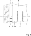
- the in Fig. 2 illustrated embodiment provided that the door leaf 5 at the lower and upper end of a vertically extending side of the door frame 4 each by means of a bearing pin 16 is rotatably mounted.
- This construction of the upper and lower hinges with journals 16 can be seen in Fig. 3 in a cutout for the lower bearing pin 16.
- a relevant mounting plate 17, which has a bearing opening 18 for the bearing pin 16, is anchored by means of fastening screws 19 at the bottom on the edge of the door leaf 5.
- the bearing pin 16 is located on a base plate 20 which is anchored in the reveal part 8 of the door frame 4 by means of fastening screws 21.
- a corresponding construction can also be found on the upper edge of door leaf 5.
- FIG. 4 shows Fig. 4 an embodiment in which it is provided that the door leaf 5 is pivotally mounted on a vertically extending side of the door frame 4 by means of concealed hinges 22.
- the door leaf 5 is pivotally mounted on a vertically extending side of the door frame 4 by means of concealed hinges 22.
- Fig. 4 Avoid recognizable problem of a possibly inadequate opening of the door leaf 5 in that the door leaf 5 is rotatably mounted on a vertically extending side of the door frame 4 by means of 180 ° hinges. In this case the hinges would be in Fig. 4 Project downwards a little to allow the door leaf 5 to be turned to the right up to 180 °.
- Fig. 2 and 4th overall show a particularly preferred arrangement of the door frame 4 and the door leaf 5 in the wall section 3 of the wall 1 such that the front visible side 13 of the door leaf 5 is flush with the wall surface 2.
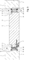
- FIG. 5 Another alternative embodiment shows Fig. 5 .
- the door leaf 5 is pivotably mounted on a vertically extending side of the door frame 4 by means of concealed hinges 7.
- the frame rebate 9 and the door rebate 11 have other dimensions, while the door leaf 5 still has a depth of preferably 60 mm and the door frame 4 has a depth of preferably 40 mm. This makes the door rebate 11 look even more delicate.
- damping profile or sealing element 10 was displaced, namely in the corner of reveal part 8 and frame rebate 9, and its shape was changed.
- the damping profile 10 here has a hollow circular cylindrical section.
- a recess 23 with two screw channels 24 is provided in the reveal part 8.
- Parts for the hinge 7 and / or fastening means for fastening the reveal part 8 to the wall 1 can be arranged in this recess 23. These can be covered by a panel 25 of the reveal part 8. This essentially results in a two-part door frame 4.
- the reveal part 8 can with conventional fasteners, which in Fig. 5 not shown, are attached to the wall 1.
- Fig. 5 shows the embodiment according to Fig. 5 no trunnion, no mounting plate and no base plate.
- the advantages of the door arrangement according to the invention result as follows:
- the door arrangement has an elegant design due to a very narrow view of the door frame 4.
- the door leaf 5 can be used as normal opening or as reverse opening. In all cases, assembly can be carried out solely by the interior fitting trade, without the involvement of the body-in-white trade or even after the painter has done his job.
- the door arrangement is completely independent of the thickness of the wall 1, in the wall cutout 3 of which the door arrangement is installed. So you can either align the door leaf to one or the other side of the wall 1 flush with the wall surface 2.
Landscapes
- Engineering & Computer Science (AREA)
- Civil Engineering (AREA)
- Structural Engineering (AREA)
- Wing Frames And Configurations (AREA)
Priority Applications (1)
| Application Number | Priority Date | Filing Date | Title |
|---|---|---|---|
| PL18197458T PL3461982T3 (pl) | 2017-09-28 | 2018-09-28 | Układ drzwi |
Applications Claiming Priority (1)
| Application Number | Priority Date | Filing Date | Title |
|---|---|---|---|
| DE202017005043.9U DE202017005043U1 (de) | 2017-09-28 | 2017-09-28 | Türanordnung |
Publications (2)
| Publication Number | Publication Date |
|---|---|
| EP3461982A1 EP3461982A1 (de) | 2019-04-03 |
| EP3461982B1 true EP3461982B1 (de) | 2020-04-22 |
Family
ID=60268543
Family Applications (1)
| Application Number | Title | Priority Date | Filing Date |
|---|---|---|---|
| EP18197458.5A Active EP3461982B1 (de) | 2017-09-28 | 2018-09-28 | Türanordnung |
Country Status (3)
| Country | Link |
|---|---|
| EP (1) | EP3461982B1 (pl) |
| DE (1) | DE202017005043U1 (pl) |
| PL (1) | PL3461982T3 (pl) |
Family Cites Families (6)
| Publication number | Priority date | Publication date | Assignee | Title |
|---|---|---|---|---|
| BE512007A (pl) * | ||||
| AT505997B1 (de) * | 2007-10-15 | 2013-02-15 | Josko Fenster Und Tueren Gmbh | Zarge |
| DE102007055182B4 (de) | 2007-11-19 | 2018-06-07 | Robert Bosch Gmbh | Einmündungs-Assistent |
| DE202010003982U1 (de) * | 2010-03-22 | 2010-08-05 | Holzbau Schmid Gmbh & Co. Kg | Brandschutz-Türzarge aus Holz |
| EP2374976A1 (de) * | 2010-04-08 | 2011-10-12 | Lueb + Wolters GmbH & Co. KG | Türzarge |
| DE202015005011U1 (de) | 2014-11-04 | 2015-10-28 | Vitadoor Gmbh & Co. Kg | Glanzglastür |
-
2017
- 2017-09-28 DE DE202017005043.9U patent/DE202017005043U1/de not_active Expired - Lifetime
-
2018
- 2018-09-28 EP EP18197458.5A patent/EP3461982B1/de active Active
- 2018-09-28 PL PL18197458T patent/PL3461982T3/pl unknown
Non-Patent Citations (1)
| Title |
|---|
| None * |
Also Published As
| Publication number | Publication date |
|---|---|
| EP3461982A1 (de) | 2019-04-03 |
| PL3461982T3 (pl) | 2020-11-16 |
| DE202017005043U1 (de) | 2017-10-25 |
Similar Documents
| Publication | Publication Date | Title |
|---|---|---|
| DE8702660U1 (de) | Fenster- oder Tür-Konstruktion mit einem bewegbar gehaltenen, verriegelbaren Flügel | |
| DE102016125605A1 (de) | Faltanlage mit Stellleiste | |
| DE69703714T2 (de) | Beschlagelement für die Anlenkung oder Verriegelung, insbesondere ein Schließstück, für Tür oder Fenster | |
| DE3104973A1 (de) | "aufschraubband, insbesondere fuer schwere fenster- oder tuerfluegel mit kunststoffprofilen" | |
| DE19719113C2 (de) | Türsystem | |
| EP1001124B1 (de) | Scharnierbeschlag für Fensterladen | |
| EP3461982B1 (de) | Türanordnung | |
| DE4318209C2 (de) | Türanschlagprofil für Schwenktüren | |
| DE4106116A1 (de) | Rahmen fuer trennwaende, insbesondere fuer duschabtrennungen u. dgl. | |
| DE10054029A1 (de) | Tür- oder Fensterflügel mit verbessertem Einbruchschutz | |
| EP1245177B1 (de) | Drehlagerung einer Tür | |
| EP1801335B1 (de) | Tür, insbesondere für Trennwandsysteme | |
| CH617981A5 (en) | Housing for a locking device | |
| DE3826189A1 (de) | Vorrichtung fuer dach-rolladen | |
| DE69804669T2 (de) | Balkonverglasung | |
| DE29617479U1 (de) | Profilrahmenwerk für Gebäudeabschlüsse | |
| EP0006439B2 (de) | Vorrichtung zur Stossstellenüberlappung an Stulpschienen | |
| DE20212002U1 (de) | Kältegerätetür | |
| DE2632927C2 (de) | Verschlußbeschlag | |
| EP0787873B1 (de) | Schliessleiste | |
| DE20004364U1 (de) | Bandanordnung für Türen, Fenster u.dgl. | |
| EP1589164B1 (de) | An eine Gebäudewand anbaubare Kabine | |
| DE2626613A1 (de) | Hebeschiebefluegel, insbesondere fuer fenster | |
| EP1098058A2 (de) | Band für Türen, Fenster und dergleichen | |
| DE2111476A1 (de) | Zarge fuer Tueren,Fenster u.dgl. |
Legal Events
| Date | Code | Title | Description |
|---|---|---|---|
| PUAI | Public reference made under article 153(3) epc to a published international application that has entered the european phase |
Free format text: ORIGINAL CODE: 0009012 |
|
| STAA | Information on the status of an ep patent application or granted ep patent |
Free format text: STATUS: THE APPLICATION HAS BEEN PUBLISHED |
|
| AK | Designated contracting states |
Kind code of ref document: A1 Designated state(s): AL AT BE BG CH CY CZ DE DK EE ES FI FR GB GR HR HU IE IS IT LI LT LU LV MC MK MT NL NO PL PT RO RS SE SI SK SM TR |
|
| AX | Request for extension of the european patent |
Extension state: BA ME |
|
| STAA | Information on the status of an ep patent application or granted ep patent |
Free format text: STATUS: REQUEST FOR EXAMINATION WAS MADE |
|
| 17P | Request for examination filed |
Effective date: 20190826 |
|
| RBV | Designated contracting states (corrected) |
Designated state(s): AL AT BE BG CH CY CZ DE DK EE ES FI FR GB GR HR HU IE IS IT LI LT LU LV MC MK MT NL NO PL PT RO RS SE SI SK SM TR |
|
| GRAP | Despatch of communication of intention to grant a patent |
Free format text: ORIGINAL CODE: EPIDOSNIGR1 |
|
| STAA | Information on the status of an ep patent application or granted ep patent |
Free format text: STATUS: GRANT OF PATENT IS INTENDED |
|
| RIC1 | Information provided on ipc code assigned before grant |
Ipc: E05D 7/081 20060101ALN20191104BHEP Ipc: E05D 3/18 20060101ALN20191104BHEP Ipc: E06B 1/04 20060101AFI20191104BHEP |
|
| INTG | Intention to grant announced |
Effective date: 20191203 |
|
| GRAS | Grant fee paid |
Free format text: ORIGINAL CODE: EPIDOSNIGR3 |
|
| GRAA | (expected) grant |
Free format text: ORIGINAL CODE: 0009210 |
|
| STAA | Information on the status of an ep patent application or granted ep patent |
Free format text: STATUS: THE PATENT HAS BEEN GRANTED |
|
| AK | Designated contracting states |
Kind code of ref document: B1 Designated state(s): AL AT BE BG CH CY CZ DE DK EE ES FI FR GB GR HR HU IE IS IT LI LT LU LV MC MK MT NL NO PL PT RO RS SE SI SK SM TR |
|
| REG | Reference to a national code |
Ref country code: CH Ref legal event code: EP |
|
| REG | Reference to a national code |
Ref country code: IE Ref legal event code: FG4D Free format text: LANGUAGE OF EP DOCUMENT: GERMAN |
|
| REG | Reference to a national code |
Ref country code: DE Ref legal event code: R096 Ref document number: 502018001262 Country of ref document: DE |
|
| REG | Reference to a national code |
Ref country code: AT Ref legal event code: REF Ref document number: 1260279 Country of ref document: AT Kind code of ref document: T Effective date: 20200515 |
|
| REG | Reference to a national code |
Ref country code: NL Ref legal event code: FP |
|
| REG | Reference to a national code |
Ref country code: LT Ref legal event code: MG4D |
|
| PG25 | Lapsed in a contracting state [announced via postgrant information from national office to epo] |
Ref country code: IS Free format text: LAPSE BECAUSE OF FAILURE TO SUBMIT A TRANSLATION OF THE DESCRIPTION OR TO PAY THE FEE WITHIN THE PRESCRIBED TIME-LIMIT Effective date: 20200822 Ref country code: NO Free format text: LAPSE BECAUSE OF FAILURE TO SUBMIT A TRANSLATION OF THE DESCRIPTION OR TO PAY THE FEE WITHIN THE PRESCRIBED TIME-LIMIT Effective date: 20200722 Ref country code: GR Free format text: LAPSE BECAUSE OF FAILURE TO SUBMIT A TRANSLATION OF THE DESCRIPTION OR TO PAY THE FEE WITHIN THE PRESCRIBED TIME-LIMIT Effective date: 20200723 Ref country code: FI Free format text: LAPSE BECAUSE OF FAILURE TO SUBMIT A TRANSLATION OF THE DESCRIPTION OR TO PAY THE FEE WITHIN THE PRESCRIBED TIME-LIMIT Effective date: 20200422 Ref country code: SE Free format text: LAPSE BECAUSE OF FAILURE TO SUBMIT A TRANSLATION OF THE DESCRIPTION OR TO PAY THE FEE WITHIN THE PRESCRIBED TIME-LIMIT Effective date: 20200422 Ref country code: PT Free format text: LAPSE BECAUSE OF FAILURE TO SUBMIT A TRANSLATION OF THE DESCRIPTION OR TO PAY THE FEE WITHIN THE PRESCRIBED TIME-LIMIT Effective date: 20200824 Ref country code: LT Free format text: LAPSE BECAUSE OF FAILURE TO SUBMIT A TRANSLATION OF THE DESCRIPTION OR TO PAY THE FEE WITHIN THE PRESCRIBED TIME-LIMIT Effective date: 20200422 |
|
| PG25 | Lapsed in a contracting state [announced via postgrant information from national office to epo] |
Ref country code: BG Free format text: LAPSE BECAUSE OF FAILURE TO SUBMIT A TRANSLATION OF THE DESCRIPTION OR TO PAY THE FEE WITHIN THE PRESCRIBED TIME-LIMIT Effective date: 20200722 Ref country code: RS Free format text: LAPSE BECAUSE OF FAILURE TO SUBMIT A TRANSLATION OF THE DESCRIPTION OR TO PAY THE FEE WITHIN THE PRESCRIBED TIME-LIMIT Effective date: 20200422 Ref country code: LV Free format text: LAPSE BECAUSE OF FAILURE TO SUBMIT A TRANSLATION OF THE DESCRIPTION OR TO PAY THE FEE WITHIN THE PRESCRIBED TIME-LIMIT Effective date: 20200422 Ref country code: HR Free format text: LAPSE BECAUSE OF FAILURE TO SUBMIT A TRANSLATION OF THE DESCRIPTION OR TO PAY THE FEE WITHIN THE PRESCRIBED TIME-LIMIT Effective date: 20200422 |
|
| PG25 | Lapsed in a contracting state [announced via postgrant information from national office to epo] |
Ref country code: AL Free format text: LAPSE BECAUSE OF FAILURE TO SUBMIT A TRANSLATION OF THE DESCRIPTION OR TO PAY THE FEE WITHIN THE PRESCRIBED TIME-LIMIT Effective date: 20200422 |
|
| REG | Reference to a national code |
Ref country code: DE Ref legal event code: R097 Ref document number: 502018001262 Country of ref document: DE |
|
| PG25 | Lapsed in a contracting state [announced via postgrant information from national office to epo] |
Ref country code: SM Free format text: LAPSE BECAUSE OF FAILURE TO SUBMIT A TRANSLATION OF THE DESCRIPTION OR TO PAY THE FEE WITHIN THE PRESCRIBED TIME-LIMIT Effective date: 20200422 Ref country code: EE Free format text: LAPSE BECAUSE OF FAILURE TO SUBMIT A TRANSLATION OF THE DESCRIPTION OR TO PAY THE FEE WITHIN THE PRESCRIBED TIME-LIMIT Effective date: 20200422 Ref country code: DK Free format text: LAPSE BECAUSE OF FAILURE TO SUBMIT A TRANSLATION OF THE DESCRIPTION OR TO PAY THE FEE WITHIN THE PRESCRIBED TIME-LIMIT Effective date: 20200422 Ref country code: RO Free format text: LAPSE BECAUSE OF FAILURE TO SUBMIT A TRANSLATION OF THE DESCRIPTION OR TO PAY THE FEE WITHIN THE PRESCRIBED TIME-LIMIT Effective date: 20200422 Ref country code: IT Free format text: LAPSE BECAUSE OF FAILURE TO SUBMIT A TRANSLATION OF THE DESCRIPTION OR TO PAY THE FEE WITHIN THE PRESCRIBED TIME-LIMIT Effective date: 20200422 Ref country code: CZ Free format text: LAPSE BECAUSE OF FAILURE TO SUBMIT A TRANSLATION OF THE DESCRIPTION OR TO PAY THE FEE WITHIN THE PRESCRIBED TIME-LIMIT Effective date: 20200422 Ref country code: ES Free format text: LAPSE BECAUSE OF FAILURE TO SUBMIT A TRANSLATION OF THE DESCRIPTION OR TO PAY THE FEE WITHIN THE PRESCRIBED TIME-LIMIT Effective date: 20200422 |
|
| PG25 | Lapsed in a contracting state [announced via postgrant information from national office to epo] |
Ref country code: SK Free format text: LAPSE BECAUSE OF FAILURE TO SUBMIT A TRANSLATION OF THE DESCRIPTION OR TO PAY THE FEE WITHIN THE PRESCRIBED TIME-LIMIT Effective date: 20200422 |
|
| PLBE | No opposition filed within time limit |
Free format text: ORIGINAL CODE: 0009261 |
|
| STAA | Information on the status of an ep patent application or granted ep patent |
Free format text: STATUS: NO OPPOSITION FILED WITHIN TIME LIMIT |
|
| 26N | No opposition filed |
Effective date: 20210125 |
|
| PG25 | Lapsed in a contracting state [announced via postgrant information from national office to epo] |
Ref country code: SI Free format text: LAPSE BECAUSE OF FAILURE TO SUBMIT A TRANSLATION OF THE DESCRIPTION OR TO PAY THE FEE WITHIN THE PRESCRIBED TIME-LIMIT Effective date: 20200422 |
|
| PG25 | Lapsed in a contracting state [announced via postgrant information from national office to epo] |
Ref country code: TR Free format text: LAPSE BECAUSE OF FAILURE TO SUBMIT A TRANSLATION OF THE DESCRIPTION OR TO PAY THE FEE WITHIN THE PRESCRIBED TIME-LIMIT Effective date: 20200422 Ref country code: MT Free format text: LAPSE BECAUSE OF FAILURE TO SUBMIT A TRANSLATION OF THE DESCRIPTION OR TO PAY THE FEE WITHIN THE PRESCRIBED TIME-LIMIT Effective date: 20200422 Ref country code: CY Free format text: LAPSE BECAUSE OF FAILURE TO SUBMIT A TRANSLATION OF THE DESCRIPTION OR TO PAY THE FEE WITHIN THE PRESCRIBED TIME-LIMIT Effective date: 20200422 |
|
| PG25 | Lapsed in a contracting state [announced via postgrant information from national office to epo] |
Ref country code: MK Free format text: LAPSE BECAUSE OF FAILURE TO SUBMIT A TRANSLATION OF THE DESCRIPTION OR TO PAY THE FEE WITHIN THE PRESCRIBED TIME-LIMIT Effective date: 20200422 Ref country code: MC Free format text: LAPSE BECAUSE OF FAILURE TO SUBMIT A TRANSLATION OF THE DESCRIPTION OR TO PAY THE FEE WITHIN THE PRESCRIBED TIME-LIMIT Effective date: 20200422 |
|
| PGFP | Annual fee paid to national office [announced via postgrant information from national office to epo] |
Ref country code: IE Payment date: 20230920 Year of fee payment: 6 Ref country code: GB Payment date: 20230920 Year of fee payment: 6 |
|
| PGFP | Annual fee paid to national office [announced via postgrant information from national office to epo] |
Ref country code: FR Payment date: 20230928 Year of fee payment: 6 |
|
| GBPC | Gb: european patent ceased through non-payment of renewal fee |
Effective date: 20240928 |
|
| PG25 | Lapsed in a contracting state [announced via postgrant information from national office to epo] |
Ref country code: GB Free format text: LAPSE BECAUSE OF NON-PAYMENT OF DUE FEES Effective date: 20240928 |
|
| PG25 | Lapsed in a contracting state [announced via postgrant information from national office to epo] |
Ref country code: FR Free format text: LAPSE BECAUSE OF NON-PAYMENT OF DUE FEES Effective date: 20240930 |
|
| PG25 | Lapsed in a contracting state [announced via postgrant information from national office to epo] |
Ref country code: IE Free format text: LAPSE BECAUSE OF NON-PAYMENT OF DUE FEES Effective date: 20240928 |
|
| REG | Reference to a national code |
Ref country code: CH Ref legal event code: U11 Free format text: ST27 STATUS EVENT CODE: U-0-0-U10-U11 (AS PROVIDED BY THE NATIONAL OFFICE) Effective date: 20251001 |
|
| PGFP | Annual fee paid to national office [announced via postgrant information from national office to epo] |
Ref country code: DE Payment date: 20250923 Year of fee payment: 8 |
|
| PGFP | Annual fee paid to national office [announced via postgrant information from national office to epo] |
Ref country code: NL Payment date: 20250918 Year of fee payment: 8 Ref country code: PL Payment date: 20250922 Year of fee payment: 8 Ref country code: LU Payment date: 20250919 Year of fee payment: 8 |
|
| PGFP | Annual fee paid to national office [announced via postgrant information from national office to epo] |
Ref country code: BE Payment date: 20250918 Year of fee payment: 8 |
|
| PGFP | Annual fee paid to national office [announced via postgrant information from national office to epo] |
Ref country code: AT Payment date: 20250919 Year of fee payment: 8 |
|
| PGFP | Annual fee paid to national office [announced via postgrant information from national office to epo] |
Ref country code: CH Payment date: 20251001 Year of fee payment: 8 |