EP3459887A1 - Spule und verfahren zur herstellung einer spule - Google Patents
Spule und verfahren zur herstellung einer spule Download PDFInfo
- Publication number
- EP3459887A1 EP3459887A1 EP18195615.2A EP18195615A EP3459887A1 EP 3459887 A1 EP3459887 A1 EP 3459887A1 EP 18195615 A EP18195615 A EP 18195615A EP 3459887 A1 EP3459887 A1 EP 3459887A1
- Authority
- EP
- European Patent Office
- Prior art keywords
- wall
- coil
- adhesive layer
- spool core
- core
- Prior art date
- Legal status (The legal status is an assumption and is not a legal conclusion. Google has not performed a legal analysis and makes no representation as to the accuracy of the status listed.)
- Granted
Links
Images




Classifications
-
- B—PERFORMING OPERATIONS; TRANSPORTING
- B65—CONVEYING; PACKING; STORING; HANDLING THIN OR FILAMENTARY MATERIAL
- B65H—HANDLING THIN OR FILAMENTARY MATERIAL, e.g. SHEETS, WEBS, CABLES
- B65H75/00—Storing webs, tapes, or filamentary material, e.g. on reels
- B65H75/02—Cores, formers, supports, or holders for coiled, wound, or folded material, e.g. reels, spindles, bobbins, cop tubes, cans, mandrels or chucks
- B65H75/04—Kinds or types
- B65H75/08—Kinds or types of circular or polygonal cross-section
- B65H75/14—Kinds or types of circular or polygonal cross-section with two end flanges
-
- B—PERFORMING OPERATIONS; TRANSPORTING
- B65—CONVEYING; PACKING; STORING; HANDLING THIN OR FILAMENTARY MATERIAL
- B65H—HANDLING THIN OR FILAMENTARY MATERIAL, e.g. SHEETS, WEBS, CABLES
- B65H75/00—Storing webs, tapes, or filamentary material, e.g. on reels
- B65H75/02—Cores, formers, supports, or holders for coiled, wound, or folded material, e.g. reels, spindles, bobbins, cop tubes, cans, mandrels or chucks
- B65H75/18—Constructional details
- B65H75/28—Arrangements for positively securing ends of material
-
- B—PERFORMING OPERATIONS; TRANSPORTING
- B65—CONVEYING; PACKING; STORING; HANDLING THIN OR FILAMENTARY MATERIAL
- B65H—HANDLING THIN OR FILAMENTARY MATERIAL, e.g. SHEETS, WEBS, CABLES
- B65H2701/00—Handled material; Storage means
- B65H2701/50—Storage means for webs, tapes, or filamentary material
- B65H2701/51—Cores or reels characterised by the material
- B65H2701/512—Cores or reels characterised by the material moulded
- B65H2701/5122—Plastics
Definitions
- the invention relates to a coil for winding or unwinding of films formed from a thermoplastic. It has a spool core with an inner wall and an outer wall, wherein the inner wall is formed to be received by a jig or a bearing pin. Moreover, the invention relates to a method for producing a coil.
- Such coils are known from the prior art and exemplified in the attached FIG. 8 shown.
- a spool can be used to feed a film to an exposure machine.
- This may be a hologram film or holofilm, which is provided by the exposure machine with a structure, in particular a hologram.
- Such coils are used to wind an exposed hologram film. Both when winding and when unwinding the film should always be kept taut, which sometimes even requires a tightening of the film by additional rotation of the coil.
- the bobbin In an exposure machine, the bobbin is placed on a tensioning device, in particular on a mandrel (Dehnspanndorn) and tensioned. While in regular film reels the spool core has a slot, the formation of a slot in the use of such a tensioning device is not possible because the interior of the spool core is filled by the mandrel. In addition, a holofilm may only be loosely wound on the spool core and not be rigidly attached. In the bobbins known from the prior art, therefore, an empty bobbin core is the operator when changing bobbins several times to wrap around with the holofilm before the holofilm remains reliable on the spool.
- a tensioning device in particular on a mandrel (Dehnspanndorn) and tensioned. While in regular film reels the spool core has a slot, the formation of a slot in the use of such a tensioning device is not possible because the interior of the spool core
- the object relating to the coil is achieved by a coil with the feature set of claim 1.
- the outer wall of the coil core is at least partially covered with an adhesive layer.
- the adhesive layer is at least partially formed from a silicone.
- the formed from a thermoplastic, preferably made of polyethylene terephthalate (PET) holofilm has very good adhesion properties on silicone.
- PET polyethylene terephthalate
- silicone and PET form a combination of materials, by which a good adhesion of the film to the outer wall of the spool core can be achieved.
- An alternative embodiment of the adhesive layer is formed by an attachable to the outer wall of the spool adhesive hose.
- This adhesive tube can be stretched or stretched applied to the spool core, so that the adhesive tube is securely fixed by its own restoring force on the spool core.
- the adhesive tube can be exchanged, preferably as a function of the material of the film. This ensures that the corresponding adhesive layers or adhesive tubes are available for different film materials.
- Another embodiment of the invention provides on one side of the spool core a coil cheek which serves to guide wound film.
- a coil cheek is disposed on both sides of the spool core.
- the coil cheek can be integrally formed with the coil core or even connected to it, in particular screwed.
- the coil cheek is associated with a detection unit for determining a number of turns of a wound on the spool core film.
- This detection unit can be formed for example in the form of a light barrier with a plurality of individual sensors, which is in communication with a higher-level control computer.
- the control computer may be configured to inform the users of the hologram exposure machine that a spool is nearly full or nearly empty, so that it can make a bobbin change shortly.
- the coil cheek comprises a display device for displaying a number of turns of a film wound on the spool core. This also allows the user a visual control of the "level" of the coil possible.
- the object relating to the method is achieved by a method according to the feature set of claim 7. It includes the following steps: Forming a spool core having an inner wall and an outer wall, and applying or forming an adhesive layer on the outer wall of the spool core. This also makes it possible to significantly save material when winding a formed from a thermoplastic film. In addition, the reliability during the exposure process is increased.
- the application of the adhesive layer comprises applying a silicone-based adhesive tube to the spool core.
- Another embodiment provides that the adhesive layer is applied to the spool core by spraying a silicone-based adhesive spray.
- a coil which can be produced particularly quickly is characterized in that the coil core is injection-molded or generatively produced with a first material component (for example plastic), and that the outer wall of the coil core is overmolded with a second material component as an adhesive layer or generatively applied as an adhesive layer to the outer wall.
- the multi-component injection molding has proved to be advantageous, since in this case can be connected together in a simple and practical way, the spool core and the adhesive layer.
- the spool core and adhesive layer can be produced by the multi-component injection molding process, a very large number of such coils.
- the spool core and adhesive layer can be made in a multi-component 3D printing process.
- FIG. 1 shows by way of example a sectional view of a coil for winding or unwinding a film 10 formed from a thermoplastic.
- the film 10 shown is formed as a holofilm, that is to say as a film 10 which can be exposed with a hologram.
- the spool includes a spool core 20 having an inner wall 21 and an outer wall 22.
- the inner wall 21 is designed to be received by a clamping device, not shown in detail, in particular by a mandrel. Also included in the invention is therefore also a system of a clamping mandrel having tensioning device with such a coil.
- the coil core 20 is formed without structures on the surface, and thus structure-free and slot-free.
- the slot-free design of the spool core 20 ensures a secure clamping by the preferably motor-operated clamping device.
- the outer wall 22 of the coil core 20 is at least partially covered with an adhesive layer 30.
- the adhesive layer 30 is arranged rotationally symmetrical about the spool core 20.
- the adhesive layer 30 is at least partially or completely formed of silicone, so that a made of a PET existing holofilm adheres very well. Other material pairings are also possible.
- the spool core 20 is completely coated with the adhesion layer 30. This means that the adhesive layer 30 extends over the entire width of the coil core 20 or its outer wall 22.
- the coil core 30 is associated with a coil cheek 40 for guiding wound film 10.
- This coil cheek 40 comprises a display device 50 for displaying a number of turns of the wound on the spool core 30 film 10.
- a "level" of the coil from the outside, i. can be seen outside the coil cheek 40 is at least one, preferably at least two slits or recesses 51 formed from an at least partially transparent material are provided.
- the coil cheek 40 additionally has two holders 60.
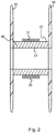
- the embodiment according to FIG. 2 differs from the one after FIG. 1 in that the adhesive layer 30 extends only partially across the width of the spool core 20.
- the adhesive layer 30 is designed as an adhesive tube 31 which can be applied to the spool core 20.
- the adhesive layer 30 is arranged centrally or centrally with respect to the spool core 20. The central arrangement is sufficient to adequately fix the film 10 to the coil.
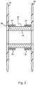
- the adhesive layer 30 is broken down into a plurality of adhesive layer sections 33, 34. In the embodiment shown, exactly two of the adhesive layer sections 33, 34 are present. A first adhesive layer portion 33 extends from the coil cheek 40 on the left side of the image and a second adhesive layer portion 34 extends from the coil cheek 40 on the right side of the image. Both adhesive layer sections 33, 34 can be applied here as an adhesive spray 32. By only partially covering the outer wall 22 of the spool core 20, a material saving with respect to the material of the adhesive layer 30 can be achieved.
- the embodiment according to FIG. 4 shows a spool core 20 having a recess 23.
- the adhesive layer 30 or an adhesive tube 31 is inserted.
- this coil it is possible to use this coil by means of a generative manufacturing process or an injection molding process manufacture.
- the spool core would be injected with a first material component or produced generatively, at the same time the recess 23 is formed.
- the outer wall 22 and in particular the recess 23 are then encapsulated with a second material component as an adhesive layer 30 or the second material component is generatively applied as an adhesive layer 30.
- the use of a recess 23 provides secure positioning and a secure position of the adhesive layer 30 on the spool core 20.
- the coils after FIGS. 5 to 7 have an only partially radially covered outer wall 22 of the spool core 20 with an adhesive layer 30. It is usually sufficient half a wrap of the spool core 20 with the film 10 to securely fix it to the adhesive layer 30 of the spool core 20. While in the embodiment according to FIG. 5 About 75 percent of the outer wall 22 are covered with the adhesive layer 30 is in the embodiment according to FIG. 6 only about half of the outer wall 22 is coated with the adhesive layer 30. The embodiment according to FIG. 7 provides a coating of the outer wall 22 of about 25 percent. This embodiment according to FIGS. 5 to 7 also cause a material saving with respect to the adhesive layer material.
- FIG. 8 For example, there is shown an example of a coil known from the prior art, wherein between four and six windings on the spool core 20 must be present to secure the film 10, so that the film 10 does not slip off the spool core 20 during tensioning and keeping tight. This problem is solved by the present invention, which reduces production losses and waste of material.
Landscapes
- Storage Of Web-Like Or Filamentary Materials (AREA)
Abstract
Description
- Die Erfindung betrifft eine Spule zur Aufwicklung oder zur Abwicklung von aus einem Thermoplasten gebildeten Filmen. Sie besitzt einen Spulenkern mit einer Innenwand und einer Außenwand, wobei die Innenwand ausgebildet ist, um von einer Spannvorrichtung oder einem Lagerstift aufgenommen zu werden. Außerdem betrifft die Erfindung ein Verfahren zur Herstellung einer Spule.
- Derartige Spulen sind aus dem Stand der Technik bekannt und exemplarisch in der beigefügten
Figur 8 dargestellt. Eine solche Spule kann verwendet werden, um einen Film einer Belichtungsmaschine zuzuführen. Dabei kann es sich um einen Hologrammfilm oder Holofilm handeln, der durch die Belichtungsmaschine mit einer Struktur, insbesondere einem Hologramm versehen wird. Aber auch ausgangsseitig werden solche Spulen eingesetzt, um einen belichteten Hologrammfilm aufzuwickeln. Sowohl beim Aufwickeln als auch beim Abwickeln ist der Film stets straff zu halten, was teilweise sogar ein Nachziehen des Filmes durch zusätzliches Verdrehen der Spule erforderlich macht. - Bei einer Belichtungsmaschine wird der Spulenkern auf eine Spannvorrichtung, insbesondere auf einen Spanndorn (Dehnspanndorn) aufgesteckt und gespannt. Während bei regulären Filmspulen der Spulenkern einen Schlitz aufweist, ist die Ausbildung eines Schlitzes beim Einsatz einer solchen Spannvorrichtung nicht möglich, da das Innere des Spulenkernes durch den Spanndorn ausgefüllt ist. Außerdem darf ein Holofilm nur locker auf den Spulenkern gewickelt sein und keinesfalls starr befestigt werden. Bei den aus dem Stand der Technik bekannten Spulen ist deshalb beim Spulenwechsel ein leerer Spulenkern vom Bediener mehrfach mit dem Holofilm zu umschlingen, bevor der Holofilm betriebssicher auf der Spule verbleibt. Üblicherweise sind mindestens vier Windungen erforderlich, damit der Film nicht wieder vom Spulenkern rutscht. Eine gestartete Produktion bzw. eine gestartete Belichtung des Holofilms muss dann wieder unterbrochen werden, was Zeit und Geld kostet. Die aus dem Stand der Technik bekannte Befestigung des Holofilms auf dem Spulenkern ist also umständlich, unsicher und nimmt unnötige Zeit in Anspruch. Außerdem wird wertvolles Filmmaterial durch die mehrfache Umwicklung des Spulenkerns verschwendet.
- Es ist daher die Aufgabe der vorliegenden Erfindung, eine Spule bereitzustellen, die die vorstehend genannten Nachteile überwindet. Außerdem ist es Aufgabe der vorliegenden Erfindung, ein Verfahren zur Herstellung einer solchen Spule anzugeben.
- Die die Spule betreffende Aufgabe wird gelöst durch eine Spule mit dem Merkmalsbestand des Anspruchs 1.
- Hierbei ist die Außenwand des Spulenkerns zumindest teilweise mit einer Haftschicht bedeckt. Dadurch ergibt sich der Vorteil, dass der Holofilm - ohne eine mechanische Verbindung - schnell, sicher aber dennoch lösbar, sowie mit geringem Materialeinsatz auf dem Spulenkern befestigt werden kann. Durch den Einsatz der Haftschicht ist es inzwischen möglich, den Film auf dem Spulenkern auch nur bei einer halben Umdrehung der Spule zu sichern. Dies bietet eine beachtliche Materialeinsparung.
- Es ist von Vorteil, wenn die Außenwand des Spulenkerns vollständig mit der Haftschicht beschichtet ist. Auch hierdurch ergibt sich eine Zeiteinsparung bei einem Spulenwechsel, denn der Bediener muss nicht denjenigen Abschnitt am Spulenkern suchen, der mit der Haftschicht belegt ist.
- Als vorteilhaft hat sich herausgestellt, wenn die Haftschicht zumindest teilweise aus einem Silikon gebildet ist. Der aus einem Thermoplasten, vorzugsweise aus Polyethylenterephtalat (PET) gebildete Holofilm weist sehr gute Hafteigenschaften an Silikon auf. Silikon und PET bilden mit anderen Worten also eine Materialpaarung, durch die eine gute Haftung des Films an der Außenwand des Spulenkerns erzielbar ist.
- Eine alternative Ausführungsform der Haftschicht ist durch einen auf die Außenwand des Spulenkerns aufsteckbaren Haftschlauch gebildet. Dieser Haftschlauch kann dehnbar oder gedehnt auf den Spulenkern aufgebracht werden, so dass der Haftschlauch durch die eigene Rückstellkraft sicher am Spulenkern fixiert ist. Außerdem lässt sich der Haftschlauch austauschen, vorzugsweise in Abhängigkeit des Materials des Films. Somit ist gewährleistet, dass für verschiedene Filmmaterialien auch die dazu korrespondierenden Haftschichten oder Haftschläuche vorliegen.
- Eine andere Ausführungsform der Erfindung sieht an einer Seite des Spulenkerns eine Spulenwange vor, die der Führung von gewickeltem Film dient. Vorzugsweise ist an beiden Seiten des Spulenkerns eine Spulenwange angeordnet. Die Spulenwange kann einteilig mit dem Spulenkern geformt sein oder auch mit ihm verbunden, insbesondere verschraubt werden.
- In einer vorteilhaften weiteren Ausgestaltung, ist der Spulenwange eine Detektionseinheit zugeordnet zur Ermittlung einer Windungsanzahl eines auf den Spulenkern gewickelten Films. Diese Detektionseinheit kann beispielsweise in Form einer Lichtschranke mit mehreren Einzelsensoren gebildet sein, die in einer Kommunikationsverbindung mit einem übergeordneten Steuerrechner steht. Der Steuerrechner kann ausgestaltet sein, den Benutzern der Hologramm-Belichtungsmaschine darüber zu informieren, dass eine Spule fast voll oder fast leer ist, damit dieser in Kürze einen Spulenwechsel vornehmen kann.
- Alternativ oder ergänzend umfasst die Spulenwange eine Anzeigevorrichtung zur Anzeige einer Windungsanzahl eines auf dem Spulenkern gewickelten Films. Auch hierdurch ist dem Benutzer eine visuelle Kontrolle des "Füllstandes" der Spule möglich.
- Die das Verfahren betreffende Aufgabe wird mit einem Verfahren gemäß dem Merkmalsbestand des Anspruchs 7 gelöst. Es umfasst die folgenden Schritte:
Ausformen eines Spulenkerns mit einer Innenwand und einer Außenwand, und Aufbringen oder Ausformen einer Haftschicht auf die Außenwand des Spulenkerns. Auch hierdurch lässt sich beim Aufwickeln eines aus einem Thermoplasten geformten Filmes erheblich Material einsparen. Außerdem ist die Betriebssicherheit beim Belichtungsvorgang erhöht. - Gemäß einer Ausführungsform umfasst das Aufbringen der Haftschicht ein Aufziehen eines auf Silikonbasis gebildeten Haftschlauches auf den Spulenkern. Eine andere Ausführungsform sieht vor, dass die Haftschicht durch Aufsprühen eines auf Silikonbasis gebildeten Haftsprays auf den Spulenkern aufgebracht wird.
- Eine besonders schnell herzustellende Spule ist dadurch gekennzeichnet, dass der Spulenkern mit einer ersten Materialkomponente (z.B. Kunststoff) gespritzt oder generativ gefertigt wird, und dass die Außenwand des Spulenkerns mit einer zweiten Materialkomponente als Haftschicht umspritzt oder generativ als Haftschicht auf die Außenwand aufgebracht wird. Insbesondere das Mehrkomponenten-Spritzgießen hat sich als vorteilhaft erwiesen, da sich hierbei der Spulenkern und die Haftschicht auf einfache und praktikable Weise miteinander verbinden lassen. Außerdem lässt sich durch das Mehrkomponenten-Spritzgussverfahren eine sehr große Stückzahl solcher Spulen herstellen. Alternativ können der Spulenkern und die Haftschicht in einem Mehrkomponenten-3D-Druckverfahren hergestellt werden.
- Im Folgenden wird die Erfindung an in der Zeichnung dargestellten Ausführungsbeispielen näher erläutert; es zeigen:
- Fig. 1
- eine Seitenansicht einer Spule, geschnitten gezeigt;
- Fig. 2
- eine Frontansicht einer weiteren Spule, teils geschnitten gezeigt;
- Fig. 3
- eine Frontansicht einer weiteren Spule, teils geschnitten gezeigt;
- Fig. 4
- eine Frontansicht einer weiteren Spule, teils geschnitten gezeigt;
- Fig. 5
- eine Seitenansicht einer Spule, geschnitten gezeigt;
- Fig. 6
- eine Seitenansicht einer Spule, geschnitten gezeigt;
- Fig. 7
- eine Seitenansicht einer Spule, geschnitten gezeigt; und
- Fig. 8
- eine aus dem Stand der Technik bekannte Spule in einer seitlichen Schnittansicht.
- Es sei vorweggeschickt, dass die Gegenstände der nachstehend erläuterten Figuren in ihren Proportionen und Maßstäben variieren können.
Figur 1 zeigt exemplarisch eine Schnittdarstellung einer Spule zur Aufwicklung oder zur Abwicklung eines aus einem Thermoplasten gebildeten Film 10. Der gezeigte Film 10 ist als ein Holofilm, mithin also als ein mit einem Hologramm belichtbarer Film 10 gebildet. Die Spule umfasst einen Spulenkern 20, der eine Innenwand 21 und eine Außenwand 22 aufweist. Die Innenwand 21 ist ausgebildet, um von einer nicht näher dargestellten Spannvorrichtung, insbesondere von einem Spanndorn aufgenommen zu werden. Ebenfalls von der Erfindung umfasst ist daher auch ein System einer einen Spanndorn aufweisenden Spannvorrichtung mit einer solchen Spule. Anders als bei Filmrollen von Kino- oder Fotografenfilmen ist der Spulenkern 20 ohne Strukturen an der Oberfläche, mithin strukturfrei und schlitzfrei gebildet. Die schlitzfreie Gestaltung des Spulenkerns 20 gewährleistet ein sicheres Spannen durch die vorzugsweise motorisch betriebene Spannvorrichtung. Bei der erfindungsgemäßen Spule ist die Außenwand 22 des Spulenkerns 20 zumindest teilweise mit einer Haftschicht 30 bedeckt. Bei dem inFigur 1 gezeigten Ausführungsbeispiel ist die Haftschicht 30 rotationssymmetrisch um den Spulenkern 20 angeordnet. Die Haftschicht 30 ist zumindest teilweise oder vollständig aus Silikon gebildet, so dass ein aus einem PET bestehender Holofilm sehr gut daran haftet. Andere Materialpaarungen sind ebenfalls möglich. - Bei dem in
Figur 1 gezeigten Ausführungsbeispiel ist der Spulenkern 20 vollständig mit der Haftschicht 30 beschichtet. Das bedeutet, dass sich die Haftschicht 30 über die vollständige Breite des Spulenkerns 20 bzw. dessen Außenwand 22 erstreckt. - Dem Spulenkern 30 ist eine Spulenwange 40 zur Führung von gewickeltem Film 10 zugeordnet. Diese Spulenwange 40 umfasst eine Anzeigevorrichtung 50 zur Anzeige einer Windungsanzahl des auf den Spulenkern 30 gewickelten Films 10. Um darüber hinaus einen "Füllstand" der Spule auch von außen, d.h. außerhalb der Spulenwange 40 sehen zu können, ist mindestens ein, vorzugsweise sind mindestens zwei aus einem zumindest teilweise transparenten Material gebildete Schlitze oder Aussparungen 51 vorgesehen. Für eine einfache Handhabung der Spule weist die Spulenwange 40 zusätzlich zwei Halterungen 60 auf.
- Das Ausführungsbeispiel nach
Figur 2 unterscheidet sich von demjenigen nachFigur 1 dadurch, dass sich die Haftschicht 30 nur teilweise über die Breite des Spulenkerns 20 erstreckt. Hier ist die Haftschicht 30 als ein auf den Spulenkern 20 aufbringbarer Haftschlauch 31 gestaltet. Die Haftschicht 30 ist mittig oder zentral bezüglich des Spulenkerns 20 angeordnet. Die zentrale Anordnung genügt, um den Film 10 an der Spule hinreichend zu fixieren. - Wie sich aus
Figur 3 ergibt, genügt es aber auch, die Haftschicht 30 nicht mittig, sondern dezentral anzuordnen. Die Haftschicht 30 zergliedert sich in mehrere Haftschichtabschnitte 33, 34. Im gezeigten Ausführungsbeispiel sind genau zwei der Haftschichtabschnitte 33, 34 vorhanden. Ein erster Haftschichtabschnitt 33 erstreckt sich von der Spulenwange 40 links im Bild und ein zweiter Haftschichtabschnitt 34 erstreckt sich von der Spulenwange 40 rechts im Bild. Beide Haftschichtabschnitte 33, 34 können hierbei als ein Haftspray 32 aufgebracht sein. Durch die nur teilweise Bedeckung der Außenwand 22 des Spulenkerns 20 lässt sich eine Materialeinsparung hinsichtlich des Materials der Haftschicht 30 erreichen. - Das Ausführungsbeispiel nach
Figur 4 zeigt einen Spulenkern 20, der eine Vertiefung 23 aufweist. In diese Vertiefung 23 oder in diese Rille ist die Haftschicht 30 oder ein Haftschlauch 31 eingesetzt. Außerdem ist es möglich, diese Spule mittels eines generativen Fertigungsverfahrens oder eines Spritzgussverfahrens herzustellen. Somit würde der Spulenkern mit einer ersten Materialkomponente gespritzt oder generativ gefertigt, wobei zugleich die Vertiefung 23 ausgeformt wird. Die Außenwand 22 und insbesondere die Vertiefung 23 werden dann mit einer zweiten Materialkomponente als Haftschicht 30 umspritzt oder die zweite Materialkomponente wird generativ als Haftschicht 30 aufgebracht. Die Verwendung einer Vertiefung 23 bietet eine sichere Positionierung und eine sichere Lage der Haftschicht 30 am Spulenkern 20. - Die Spulen nach
Figuren 5 bis 7 weisen eine nur teilweise radial bedeckte Außenwand 22 des Spulenkerns 20 mit einer Haftschicht 30 auf. Es genügt in der Regel eine halbe Umwicklung des Spulenkerns 20 mit dem Film 10, um ihn sicher an der Haftschicht 30 des Spulenkerns 20 zu fixieren. Während beim Ausführungsbeispiel nachFigur 5 ungefähr 75 Prozent der Außenwand 22 mit der Haftschicht 30 bedeckt sind, ist beim Ausführungsbeispiel nachFigur 6 nur ungefähr die Hälfte der Außenwand 22 mit der Haftschicht 30 beschichtet. Das Ausführungsbeispiel nachFigur 7 sieht eine Beschichtung der Außenwand 22 von ungefähr 25 Prozent vor. Diese Ausführungsform nachFiguren 5 bis 7 bewirken ebenfalls eine Materialeinsparung hinsichtlich des Haftschichtmaterials. - In
Figur 8 ist ein aus dem Stand der Technik bekanntes Beispiel für eine Spule gezeigt, wobei hier zur Sicherung des Films 10 zwischen vier und sechs Wicklungen auf dem Spulenkern 20 vorhanden sein müssen, damit der Film 10 beim Straffziehen und Straffhalten nicht vom Spulenkern 20 rutscht. Dieses Problem wird durch die vorliegende Erfindung behoben, womit Produktionsausfälle und eine Materialverschwendung dezimiert werden. -
- 10
- Film
- 20
- Spulenkern
- 21
- Innenwand
- 22
- Außenwand
- 23
- Vertiefung
- 30
- Haftschicht
- 31
- Haftschlauch
- 32
- Haftspray
- 33
- erster Haftschichtabschnitt
- 34
- zweiter Haftschichtabschnitt
- 40
- Spulenwange
- 50
- Anzeigevorrichtung
- 51
- Aussparung
- 60
- Halterung
Claims (10)
- Spule zur Aufwicklung oder zur Abwicklung von aus einem Thermoplasten gebildeten Filmen (1), mit einem eine Innenwand (21) und eine Außenwand (22) aufweisenden Spulenkern (20), bei welchem die Innenwand (21) ausgebildet ist, um von einer Spannvorrichtung oder einem Lagerstift aufgenommen zu werden, dadurch gekennzeichnet, dass bei welchem die Außenwand (22) des Spulenkerns zumindest teilweise mit einer Haftschicht (30) bedeckt ist.
- Spule nach Anspruch 1, dadurch gekennzeichnet, dass die Außenwand (22) des Spulenkerns (20) vollständig mit der Haftschicht (30) beschichtet ist.
- Spule nach Anspruch 1 oder 2, dadurch gekennzeichnet, dass die Haftschicht (30) zumindest teilweise aus einem Silikon gebildet ist.
- Spule nach einem der Ansprüche 1 bis 3, dadurch gekennzeichnet, dass die Haftschicht (30) als ein auf die Außenwand (22) des Spulenkerns (2) aufsteckbarer Haftschlauch (31) gebildet ist.
- Spule nach einem der Ansprüche 1 bis 4, dadurch gekennzeichnet, dass zumindest einer Seite des Spulenkerns (30) eine Spulenwange (40) zur Führung von gewickeltem Film (10) zugeordnet ist.
- Spule nach Anspruch 5, dadurch gekennzeichnet, dass der Spulenwange (40) eine Detektionseinheit zugeordnet ist zur Ermittlung einer Windungsanzahl eines auf dem Spulenkern (30) gewickelten Films (10).
- Verfahren zur Herstellung einer Spule nach einem der Ansprüche 1 bis 6 gekennzeichnet durch die folgenden Schritte:A) Ausformen eines Spulenkerns (20) mit einer Innenwand (21) und einer Außenwand (22), undB) Aufbringen oder Ausformen einer Haftschicht (30) auf die Außenwand (22) des Spulenkerns (30).
- Verfahren nach Anspruch 7, dadurch gekennzeichnet, dass das Aufbringen der Haftschicht ein Aufziehen eines auf Silikonbasis gebildeten Haftschlauches (31) auf den Spulenkern (20) umfasst.
- Verfahren nach Anspruch 7, dadurch gekennzeichnet, dass das Aufbringen der Haftschicht (30) ein Aufsprühen eines auf Silikonbasis gebildeten Haftsprays (32) auf den Spulenkern (32) umfasst.
- Verfahren nach Anspruch 7, dadurch gekennzeichnet, dass der Spulenkern (20) mit einer ersten Materialkomponente gespritzt oder generativ gefertigt wird, und dass die Außenwand (22) des Spulenkerns (20) mit einer zweiten Materialkomponente als Haftschicht (30) umspritzt oder die zweite Materialkomponente generativ als Haftschicht (30) auf die Außenwand (22) aufgebracht wird.
Applications Claiming Priority (1)
| Application Number | Priority Date | Filing Date | Title |
|---|---|---|---|
| DE102017121907.2A DE102017121907A1 (de) | 2017-09-21 | 2017-09-21 | Spule und Verfahren zur Herstellung einer Spule |
Publications (2)
| Publication Number | Publication Date |
|---|---|
| EP3459887A1 true EP3459887A1 (de) | 2019-03-27 |
| EP3459887B1 EP3459887B1 (de) | 2023-03-15 |
Family
ID=63667726
Family Applications (1)
| Application Number | Title | Priority Date | Filing Date |
|---|---|---|---|
| EP18195615.2A Active EP3459887B1 (de) | 2017-09-21 | 2018-09-20 | Spule und verfahren zur herstellung einer spule |
Country Status (2)
| Country | Link |
|---|---|
| EP (1) | EP3459887B1 (de) |
| DE (1) | DE102017121907A1 (de) |
Citations (8)
| Publication number | Priority date | Publication date | Assignee | Title |
|---|---|---|---|---|
| US3030045A (en) * | 1957-11-22 | 1962-04-17 | Ampex | Tape reel |
| US3493161A (en) * | 1967-04-17 | 1970-02-03 | Eastman Kodak Co | Web support roller surface |
| US3499376A (en) * | 1967-02-13 | 1970-03-10 | Coleman Eng Co Inc | Removable cassette camera with film severing mechanism |
| DE7832838U1 (de) * | 1978-11-04 | 1979-02-22 | Steinbusch, Horst Heinrich, 5110 Alsdorf | Vorrichtung zum auf- und abspulen eines endlosen filmes o.dgl. |
| US4699489A (en) * | 1979-11-19 | 1987-10-13 | Konishiroku Photo Industry Co., Ltd. | Film winding member |
| WO2010043677A1 (de) * | 2008-10-16 | 2010-04-22 | Continental Automotive Gmbh | Verfahren und vorrichtung zur herstellung eines piezokörpers |
| EP3059196A1 (de) * | 2010-12-17 | 2016-08-24 | 3M Innovative Properties Company | Folienwickelkern mit offenem spalt |
| CN106190018A (zh) * | 2016-08-08 | 2016-12-07 | 岳胜武 | 可喷涂的自粘接型环保硅胶胶水及其制备方法 |
Family Cites Families (7)
| Publication number | Priority date | Publication date | Assignee | Title |
|---|---|---|---|---|
| US3321149A (en) * | 1966-03-24 | 1967-05-23 | Bausch & Lomb | Chart roll spindle |
| US4437742A (en) * | 1980-10-09 | 1984-03-20 | Minolta Camera Kabushiki Kaisha | Camera capable of automatically responding to data coded on film |
| DE4206143C2 (de) * | 1992-02-28 | 1994-03-24 | Agfa Gevaert Ag | Vorrichtung zum Befestigen des freien Endes eines folienartigen Materials auf einem zylinderförmigen Wickelkern |
| US5321455A (en) * | 1992-12-09 | 1994-06-14 | Eastman Kodak Company | Camera apparatus and method for film double exposure prevention |
| US5816525A (en) * | 1996-01-10 | 1998-10-06 | Agfa-Gevaert | Winding core |
| DE202009017716U1 (de) * | 2009-12-22 | 2010-04-08 | Paul Sauer Gmbh & Co. Walzenfabrik Kg | Wickelhülse mit Beschichtung |
| JP5982158B2 (ja) * | 2012-04-06 | 2016-08-31 | デクセリアルズ株式会社 | リール部材 |
-
2017
- 2017-09-21 DE DE102017121907.2A patent/DE102017121907A1/de active Pending
-
2018
- 2018-09-20 EP EP18195615.2A patent/EP3459887B1/de active Active
Patent Citations (8)
| Publication number | Priority date | Publication date | Assignee | Title |
|---|---|---|---|---|
| US3030045A (en) * | 1957-11-22 | 1962-04-17 | Ampex | Tape reel |
| US3499376A (en) * | 1967-02-13 | 1970-03-10 | Coleman Eng Co Inc | Removable cassette camera with film severing mechanism |
| US3493161A (en) * | 1967-04-17 | 1970-02-03 | Eastman Kodak Co | Web support roller surface |
| DE7832838U1 (de) * | 1978-11-04 | 1979-02-22 | Steinbusch, Horst Heinrich, 5110 Alsdorf | Vorrichtung zum auf- und abspulen eines endlosen filmes o.dgl. |
| US4699489A (en) * | 1979-11-19 | 1987-10-13 | Konishiroku Photo Industry Co., Ltd. | Film winding member |
| WO2010043677A1 (de) * | 2008-10-16 | 2010-04-22 | Continental Automotive Gmbh | Verfahren und vorrichtung zur herstellung eines piezokörpers |
| EP3059196A1 (de) * | 2010-12-17 | 2016-08-24 | 3M Innovative Properties Company | Folienwickelkern mit offenem spalt |
| CN106190018A (zh) * | 2016-08-08 | 2016-12-07 | 岳胜武 | 可喷涂的自粘接型环保硅胶胶水及其制备方法 |
Also Published As
| Publication number | Publication date |
|---|---|
| EP3459887B1 (de) | 2023-03-15 |
| DE102017121907A1 (de) | 2019-03-21 |
Similar Documents
| Publication | Publication Date | Title |
|---|---|---|
| DE7311896U (de) | Spulenkoerper insbesondere fuer bandfoermige aufzeichnungstraeger | |
| DE3221221A1 (de) | Vorrichtung zum aufwickeln von baendern, insbesondere fotografischen schichttraegern in bandform | |
| DE10150818B4 (de) | Wickel- oder Bandagiervorrichtung und Ringkernspulen-Wickel- und Bandagiersystem | |
| WO1999024344A1 (de) | Verfahren und vorrichtung zum aufspulen eines kontinuierlich zulaufenden fadens | |
| DE1940580C3 (de) | Verfahren zur maschinellen Herstellung einer Spule | |
| DE102010031959A1 (de) | Verfahren zum Herstellen einer Textilspule und Arbeitsstelle zur Durchführung des Verfahrens | |
| EP3459887B1 (de) | Spule und verfahren zur herstellung einer spule | |
| DE69622093T2 (de) | Anwendung eines UV-härtbaren Klebers zur Herstellung einer Abspulvorrichtung von Glasfasern | |
| DE2637016C2 (de) | ||
| DE1919857A1 (de) | Vorrichtung zur Steuerung des Transports eines um eine Spule od.dgl. aufgespulten bandfoermigen Koerpers,wie eines Filmes od.dgl. | |
| DE10153896A1 (de) | Direktwickelvorrichtung und -verfahren | |
| DE1913724U (de) | Spule. | |
| DE2656326A1 (de) | Spulenkoerper fuer garne, faeden o.dgl. | |
| EP1481930B1 (de) | Spulmaschine | |
| EP2468669B1 (de) | Verfahren zur Herstellung einer Färbespule | |
| DE2362485A1 (de) | Spule fuer eine maschine zur umhuellung von kabeln | |
| DE60120253T2 (de) | Elastisches-Garn Wickel und Verfahren zum Betrieb einer Aufwickelmaschine für elastische Garne | |
| DE890716C (de) | Einrichtung zur selbsttätigen Befestigung von Magnetogrammträgern und Filmen in den Aufwickelspulen | |
| DE2820674A1 (de) | Ringkernspulen-wickelvorrichtung | |
| DE826694C (de) | Photographisches Entwicklungsgeraet | |
| DE102012023559A1 (de) | Verfahren zur Herstellung einer als Kreuzspule ausgebildeten Färbespule | |
| EP3855462B9 (de) | Vorrichtung und verfahren zum magazinlosen bewickeln von ringkernen | |
| DE102016215953A1 (de) | Wickelverfahren und Wickelvorrichtung zum kontinuierlichen Bewickeln eines Kernes | |
| DE1810002C3 (de) | Verfahren zur Herstellung von Verstärkungsrippen auf Wickelkörpern | |
| DE2809015A1 (de) | Filmprojektor oder betrachter |
Legal Events
| Date | Code | Title | Description |
|---|---|---|---|
| PUAI | Public reference made under article 153(3) epc to a published international application that has entered the european phase |
Free format text: ORIGINAL CODE: 0009012 |
|
| STAA | Information on the status of an ep patent application or granted ep patent |
Free format text: STATUS: THE APPLICATION HAS BEEN PUBLISHED |
|
| AK | Designated contracting states |
Kind code of ref document: A1 Designated state(s): AL AT BE BG CH CY CZ DE DK EE ES FI FR GB GR HR HU IE IS IT LI LT LU LV MC MK MT NL NO PL PT RO RS SE SI SK SM TR |
|
| AX | Request for extension of the european patent |
Extension state: BA ME |
|
| STAA | Information on the status of an ep patent application or granted ep patent |
Free format text: STATUS: REQUEST FOR EXAMINATION WAS MADE |
|
| 17P | Request for examination filed |
Effective date: 20190820 |
|
| RBV | Designated contracting states (corrected) |
Designated state(s): AL AT BE BG CH CY CZ DE DK EE ES FI FR GB GR HR HU IE IS IT LI LT LU LV MC MK MT NL NO PL PT RO RS SE SI SK SM TR |
|
| STAA | Information on the status of an ep patent application or granted ep patent |
Free format text: STATUS: EXAMINATION IS IN PROGRESS |
|
| 17Q | First examination report despatched |
Effective date: 20200303 |
|
| GRAP | Despatch of communication of intention to grant a patent |
Free format text: ORIGINAL CODE: EPIDOSNIGR1 |
|
| STAA | Information on the status of an ep patent application or granted ep patent |
Free format text: STATUS: GRANT OF PATENT IS INTENDED |
|
| INTG | Intention to grant announced |
Effective date: 20221103 |
|
| GRAS | Grant fee paid |
Free format text: ORIGINAL CODE: EPIDOSNIGR3 |
|
| GRAA | (expected) grant |
Free format text: ORIGINAL CODE: 0009210 |
|
| STAA | Information on the status of an ep patent application or granted ep patent |
Free format text: STATUS: THE PATENT HAS BEEN GRANTED |
|
| AK | Designated contracting states |
Kind code of ref document: B1 Designated state(s): AL AT BE BG CH CY CZ DE DK EE ES FI FR GB GR HR HU IE IS IT LI LT LU LV MC MK MT NL NO PL PT RO RS SE SI SK SM TR |
|
| REG | Reference to a national code |
Ref country code: CH Ref legal event code: EP Ref country code: GB Ref legal event code: FG4D Free format text: NOT ENGLISH |
|
| REG | Reference to a national code |
Ref country code: DE Ref legal event code: R096 Ref document number: 502018011757 Country of ref document: DE |
|
| REG | Reference to a national code |
Ref country code: IE Ref legal event code: FG4D Free format text: LANGUAGE OF EP DOCUMENT: GERMAN |
|
| REG | Reference to a national code |
Ref country code: AT Ref legal event code: REF Ref document number: 1553915 Country of ref document: AT Kind code of ref document: T Effective date: 20230415 |
|
| P01 | Opt-out of the competence of the unified patent court (upc) registered |
Effective date: 20230526 |
|
| REG | Reference to a national code |
Ref country code: LT Ref legal event code: MG9D |
|
| REG | Reference to a national code |
Ref country code: NL Ref legal event code: MP Effective date: 20230315 |
|
| PG25 | Lapsed in a contracting state [announced via postgrant information from national office to epo] |
Ref country code: RS Free format text: LAPSE BECAUSE OF FAILURE TO SUBMIT A TRANSLATION OF THE DESCRIPTION OR TO PAY THE FEE WITHIN THE PRESCRIBED TIME-LIMIT Effective date: 20230315 Ref country code: NO Free format text: LAPSE BECAUSE OF FAILURE TO SUBMIT A TRANSLATION OF THE DESCRIPTION OR TO PAY THE FEE WITHIN THE PRESCRIBED TIME-LIMIT Effective date: 20230615 Ref country code: LV Free format text: LAPSE BECAUSE OF FAILURE TO SUBMIT A TRANSLATION OF THE DESCRIPTION OR TO PAY THE FEE WITHIN THE PRESCRIBED TIME-LIMIT Effective date: 20230315 Ref country code: LT Free format text: LAPSE BECAUSE OF FAILURE TO SUBMIT A TRANSLATION OF THE DESCRIPTION OR TO PAY THE FEE WITHIN THE PRESCRIBED TIME-LIMIT Effective date: 20230315 Ref country code: HR Free format text: LAPSE BECAUSE OF FAILURE TO SUBMIT A TRANSLATION OF THE DESCRIPTION OR TO PAY THE FEE WITHIN THE PRESCRIBED TIME-LIMIT Effective date: 20230315 |
|
| PG25 | Lapsed in a contracting state [announced via postgrant information from national office to epo] |
Ref country code: SE Free format text: LAPSE BECAUSE OF FAILURE TO SUBMIT A TRANSLATION OF THE DESCRIPTION OR TO PAY THE FEE WITHIN THE PRESCRIBED TIME-LIMIT Effective date: 20230315 Ref country code: NL Free format text: LAPSE BECAUSE OF FAILURE TO SUBMIT A TRANSLATION OF THE DESCRIPTION OR TO PAY THE FEE WITHIN THE PRESCRIBED TIME-LIMIT Effective date: 20230315 Ref country code: GR Free format text: LAPSE BECAUSE OF FAILURE TO SUBMIT A TRANSLATION OF THE DESCRIPTION OR TO PAY THE FEE WITHIN THE PRESCRIBED TIME-LIMIT Effective date: 20230616 Ref country code: FI Free format text: LAPSE BECAUSE OF FAILURE TO SUBMIT A TRANSLATION OF THE DESCRIPTION OR TO PAY THE FEE WITHIN THE PRESCRIBED TIME-LIMIT Effective date: 20230315 |
|
| PG25 | Lapsed in a contracting state [announced via postgrant information from national office to epo] |
Ref country code: SM Free format text: LAPSE BECAUSE OF FAILURE TO SUBMIT A TRANSLATION OF THE DESCRIPTION OR TO PAY THE FEE WITHIN THE PRESCRIBED TIME-LIMIT Effective date: 20230315 Ref country code: RO Free format text: LAPSE BECAUSE OF FAILURE TO SUBMIT A TRANSLATION OF THE DESCRIPTION OR TO PAY THE FEE WITHIN THE PRESCRIBED TIME-LIMIT Effective date: 20230315 Ref country code: PT Free format text: LAPSE BECAUSE OF FAILURE TO SUBMIT A TRANSLATION OF THE DESCRIPTION OR TO PAY THE FEE WITHIN THE PRESCRIBED TIME-LIMIT Effective date: 20230717 Ref country code: ES Free format text: LAPSE BECAUSE OF FAILURE TO SUBMIT A TRANSLATION OF THE DESCRIPTION OR TO PAY THE FEE WITHIN THE PRESCRIBED TIME-LIMIT Effective date: 20230315 Ref country code: EE Free format text: LAPSE BECAUSE OF FAILURE TO SUBMIT A TRANSLATION OF THE DESCRIPTION OR TO PAY THE FEE WITHIN THE PRESCRIBED TIME-LIMIT Effective date: 20230315 Ref country code: CZ Free format text: LAPSE BECAUSE OF FAILURE TO SUBMIT A TRANSLATION OF THE DESCRIPTION OR TO PAY THE FEE WITHIN THE PRESCRIBED TIME-LIMIT Effective date: 20230315 |
|
| PG25 | Lapsed in a contracting state [announced via postgrant information from national office to epo] |
Ref country code: SK Free format text: LAPSE BECAUSE OF FAILURE TO SUBMIT A TRANSLATION OF THE DESCRIPTION OR TO PAY THE FEE WITHIN THE PRESCRIBED TIME-LIMIT Effective date: 20230315 Ref country code: PL Free format text: LAPSE BECAUSE OF FAILURE TO SUBMIT A TRANSLATION OF THE DESCRIPTION OR TO PAY THE FEE WITHIN THE PRESCRIBED TIME-LIMIT Effective date: 20230315 Ref country code: IS Free format text: LAPSE BECAUSE OF FAILURE TO SUBMIT A TRANSLATION OF THE DESCRIPTION OR TO PAY THE FEE WITHIN THE PRESCRIBED TIME-LIMIT Effective date: 20230715 |
|
| REG | Reference to a national code |
Ref country code: DE Ref legal event code: R097 Ref document number: 502018011757 Country of ref document: DE |
|
| PLBE | No opposition filed within time limit |
Free format text: ORIGINAL CODE: 0009261 |
|
| STAA | Information on the status of an ep patent application or granted ep patent |
Free format text: STATUS: NO OPPOSITION FILED WITHIN TIME LIMIT |
|
| PG25 | Lapsed in a contracting state [announced via postgrant information from national office to epo] |
Ref country code: SI Free format text: LAPSE BECAUSE OF FAILURE TO SUBMIT A TRANSLATION OF THE DESCRIPTION OR TO PAY THE FEE WITHIN THE PRESCRIBED TIME-LIMIT Effective date: 20230315 Ref country code: DK Free format text: LAPSE BECAUSE OF FAILURE TO SUBMIT A TRANSLATION OF THE DESCRIPTION OR TO PAY THE FEE WITHIN THE PRESCRIBED TIME-LIMIT Effective date: 20230315 |
|
| 26N | No opposition filed |
Effective date: 20231218 |
|
| REG | Reference to a national code |
Ref country code: CH Ref legal event code: PL |
|
| PG25 | Lapsed in a contracting state [announced via postgrant information from national office to epo] |
Ref country code: LU Free format text: LAPSE BECAUSE OF NON-PAYMENT OF DUE FEES Effective date: 20230920 |
|
| REG | Reference to a national code |
Ref country code: BE Ref legal event code: MM Effective date: 20230930 |
|
| PG25 | Lapsed in a contracting state [announced via postgrant information from national office to epo] |
Ref country code: LU Free format text: LAPSE BECAUSE OF NON-PAYMENT OF DUE FEES Effective date: 20230920 Ref country code: IT Free format text: LAPSE BECAUSE OF FAILURE TO SUBMIT A TRANSLATION OF THE DESCRIPTION OR TO PAY THE FEE WITHIN THE PRESCRIBED TIME-LIMIT Effective date: 20230315 Ref country code: MC Free format text: LAPSE BECAUSE OF FAILURE TO SUBMIT A TRANSLATION OF THE DESCRIPTION OR TO PAY THE FEE WITHIN THE PRESCRIBED TIME-LIMIT Effective date: 20230315 |
|
| REG | Reference to a national code |
Ref country code: IE Ref legal event code: MM4A |
|
| PG25 | Lapsed in a contracting state [announced via postgrant information from national office to epo] |
Ref country code: IE Free format text: LAPSE BECAUSE OF NON-PAYMENT OF DUE FEES Effective date: 20230920 |
|
| PG25 | Lapsed in a contracting state [announced via postgrant information from national office to epo] |
Ref country code: CH Free format text: LAPSE BECAUSE OF NON-PAYMENT OF DUE FEES Effective date: 20230930 |
|
| PG25 | Lapsed in a contracting state [announced via postgrant information from national office to epo] |
Ref country code: IE Free format text: LAPSE BECAUSE OF NON-PAYMENT OF DUE FEES Effective date: 20230920 Ref country code: CH Free format text: LAPSE BECAUSE OF NON-PAYMENT OF DUE FEES Effective date: 20230930 |
|
| PG25 | Lapsed in a contracting state [announced via postgrant information from national office to epo] |
Ref country code: BE Free format text: LAPSE BECAUSE OF NON-PAYMENT OF DUE FEES Effective date: 20230930 |
|
| PG25 | Lapsed in a contracting state [announced via postgrant information from national office to epo] |
Ref country code: BG Free format text: LAPSE BECAUSE OF FAILURE TO SUBMIT A TRANSLATION OF THE DESCRIPTION OR TO PAY THE FEE WITHIN THE PRESCRIBED TIME-LIMIT Effective date: 20230315 |
|
| REG | Reference to a national code |
Ref country code: AT Ref legal event code: MM01 Ref document number: 1553915 Country of ref document: AT Kind code of ref document: T Effective date: 20230920 |
|
| PG25 | Lapsed in a contracting state [announced via postgrant information from national office to epo] |
Ref country code: BG Free format text: LAPSE BECAUSE OF FAILURE TO SUBMIT A TRANSLATION OF THE DESCRIPTION OR TO PAY THE FEE WITHIN THE PRESCRIBED TIME-LIMIT Effective date: 20230315 |
|
| PG25 | Lapsed in a contracting state [announced via postgrant information from national office to epo] |
Ref country code: AT Free format text: LAPSE BECAUSE OF NON-PAYMENT OF DUE FEES Effective date: 20230920 |
|
| PG25 | Lapsed in a contracting state [announced via postgrant information from national office to epo] |
Ref country code: AT Free format text: LAPSE BECAUSE OF NON-PAYMENT OF DUE FEES Effective date: 20230920 |
|
| PG25 | Lapsed in a contracting state [announced via postgrant information from national office to epo] |
Ref country code: CY Free format text: LAPSE BECAUSE OF FAILURE TO SUBMIT A TRANSLATION OF THE DESCRIPTION OR TO PAY THE FEE WITHIN THE PRESCRIBED TIME-LIMIT; INVALID AB INITIO Effective date: 20180920 |
|
| PG25 | Lapsed in a contracting state [announced via postgrant information from national office to epo] |
Ref country code: HU Free format text: LAPSE BECAUSE OF FAILURE TO SUBMIT A TRANSLATION OF THE DESCRIPTION OR TO PAY THE FEE WITHIN THE PRESCRIBED TIME-LIMIT; INVALID AB INITIO Effective date: 20180920 |
|
| PGFP | Annual fee paid to national office [announced via postgrant information from national office to epo] |
Ref country code: DE Payment date: 20250919 Year of fee payment: 8 |
|
| PGFP | Annual fee paid to national office [announced via postgrant information from national office to epo] |
Ref country code: GB Payment date: 20250923 Year of fee payment: 8 |
|
| PGFP | Annual fee paid to national office [announced via postgrant information from national office to epo] |
Ref country code: FR Payment date: 20250926 Year of fee payment: 8 |
|
| PG25 | Lapsed in a contracting state [announced via postgrant information from national office to epo] |
Ref country code: TR Free format text: LAPSE BECAUSE OF FAILURE TO SUBMIT A TRANSLATION OF THE DESCRIPTION OR TO PAY THE FEE WITHIN THE PRESCRIBED TIME-LIMIT Effective date: 20230315 |