EP3459760B1 - Dispositif absorbeur de bruit pour roue de véhicule ferroviaire et roue de véhicule ferroviaire associée - Google Patents
Dispositif absorbeur de bruit pour roue de véhicule ferroviaire et roue de véhicule ferroviaire associée Download PDFInfo
- Publication number
- EP3459760B1 EP3459760B1 EP18195733.3A EP18195733A EP3459760B1 EP 3459760 B1 EP3459760 B1 EP 3459760B1 EP 18195733 A EP18195733 A EP 18195733A EP 3459760 B1 EP3459760 B1 EP 3459760B1
- Authority
- EP
- European Patent Office
- Prior art keywords
- noise
- wheel
- strip
- railway vehicle
- absorbing
- Prior art date
- Legal status (The legal status is an assumption and is not a legal conclusion. Google has not performed a legal analysis and makes no representation as to the accuracy of the status listed.)
- Active
Links
Images


Classifications
-
- B—PERFORMING OPERATIONS; TRANSPORTING
- B60—VEHICLES IN GENERAL
- B60B—VEHICLE WHEELS; CASTORS; AXLES FOR WHEELS OR CASTORS; INCREASING WHEEL ADHESION
- B60B17/00—Wheels characterised by rail-engaging elements
- B60B17/0006—Construction of wheel bodies, e.g. disc wheels
- B60B17/0024—Construction of wheel bodies, e.g. disc wheels with noise reducing means
-
- B—PERFORMING OPERATIONS; TRANSPORTING
- B60—VEHICLES IN GENERAL
- B60B—VEHICLE WHEELS; CASTORS; AXLES FOR WHEELS OR CASTORS; INCREASING WHEEL ADHESION
- B60B17/00—Wheels characterised by rail-engaging elements
- B60B17/0027—Resilient wheels, e.g. resilient hubs
- B60B17/0031—Resilient wheels, e.g. resilient hubs using springs
- B60B17/0034—Resilient wheels, e.g. resilient hubs using springs of rubber or other non-metallic material
-
- B—PERFORMING OPERATIONS; TRANSPORTING
- B60—VEHICLES IN GENERAL
- B60B—VEHICLE WHEELS; CASTORS; AXLES FOR WHEELS OR CASTORS; INCREASING WHEEL ADHESION
- B60B17/00—Wheels characterised by rail-engaging elements
- B60B17/0003—Wheel bodies characterised by use of non-metallic material
-
- B—PERFORMING OPERATIONS; TRANSPORTING
- B60—VEHICLES IN GENERAL
- B60B—VEHICLE WHEELS; CASTORS; AXLES FOR WHEELS OR CASTORS; INCREASING WHEEL ADHESION
- B60B2900/00—Purpose of invention
- B60B2900/10—Reduction of
- B60B2900/131—Vibrations
-
- B—PERFORMING OPERATIONS; TRANSPORTING
- B60—VEHICLES IN GENERAL
- B60B—VEHICLE WHEELS; CASTORS; AXLES FOR WHEELS OR CASTORS; INCREASING WHEEL ADHESION
- B60B2900/00—Purpose of invention
- B60B2900/10—Reduction of
- B60B2900/133—Noise
-
- B—PERFORMING OPERATIONS; TRANSPORTING
- B60—VEHICLES IN GENERAL
- B60Y—INDEXING SCHEME RELATING TO ASPECTS CROSS-CUTTING VEHICLE TECHNOLOGY
- B60Y2200/00—Type of vehicle
- B60Y2200/30—Railway vehicles
Definitions
- the present invention relates to a noise absorber device for a railway vehicle wheel, of the type comprising at least one blade extending radially from a connection end adapted to be fixed at the periphery of the wheel, to a free end, and at least one damping mass fixed on one face of the free end of the blade, away from the connecting end.
- Such a device is known in the state of the art as the dynamic absorber or drummer (see for example DE 20 2006 012852 U1 )
- the device is attached to the railway vehicle wheel by means of the blade which is generally ring-shaped.
- the dynamic beater acts as a resonator sized to vibrate at a specific frequency depending on the rigidity and mass of the dynamic beater.
- the dynamic beater is able to damp a natural frequency of a mode of axial vibration of the wheel at the origin of squealing.
- This device has a disadvantage because it reduces the squeal generated by the wheels only on a very narrow frequency band centered on the resonant frequency of the dynamic beater.
- a dynamic beater does not dampen the vibration modes of the wheel other than those for which it is set.
- An object of the invention is therefore to provide a noise absorber device for a railway vehicle wheel, capable of attenuating squeal over a wide range of frequencies both around the frequencies of the low order vibration modes and also at the higher frequency content level corresponding to higher order vibratory modes.
- the invention relates to a noise absorber device for a railway vehicle wheel of the aforementioned type, characterized in that the blade comprises at least two metal layers and at least one layer of viscoelastic material sandwiched between the two layers metal.
- the invention also relates to a wheel for a railway vehicle comprising at least one noise-absorbing device as defined above.
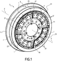
- the Figure 1 presents four noise-absorbing devices 1 also called anti-squeal devices fixed on a wheel 3 of a railway vehicle.
- the railway vehicle is for example a metro, a tramway or any other rail vehicle carrying passengers or freight.
- the wheel 3 of axis XX comprises a tire 5 delimiting a tread 7 in contact with the surface of the top of the rail (not shown) and a lateral bead 9, which guards the wheel 3 by bearing on the face Lateral rail.
- the lateral bead 9 projects radially and is oriented towards the inside of the rails.
- the wheel 3 further comprises a hub 11 and is fixed to an axle or a rocket, either by setting or by bolting (not shown).
- the sound absorbing device 1, shown on the Figure 2 has an annular sector shape.
- the noise absorbing device 1 comprises an outer blade 13A and an inner blade 13B which extend radially from a connecting end 15A, 15B fixed to the periphery of the wheel 3, to a free end 17A, 17B, directed towards the center of the wheel 3.
- the blades 13A, 13B extend in the plane of the wheel, i.e. perpendicular to the X-X axis of the wheel 3. They have an annular sector shape and are parallel to each other.
- Each of the blades 13A, 13B comprises an inner face and an outer face, the inner face of the blade 13A being positioned facing the outer face of the blade 13B.
- the device 1 further comprises damping masses 19A, 19B, 19C fixed on the inner and outer faces of the free ends 17A, 17B of the blades 13A, 13B, away from the connecting ends 15A, 15B.
- the device 1 comprises a first damping mass 19A fixed on the outer face of the free end 17A, a second damping mass 19B clamped between the inner face of the free end 17A and the outer face of the free end 17B and a third damping mass fixed on the inner face of the free end 17B.
- the fastening flange 23 comprises two lateral attachment flanges 25 between which the connecting ends 15A, 15B of the blades 13A, 13B are clamped together and an intermediate fixing flange 29.
- the intermediate fixing flange 29 makes it possible to maintain a constant spacing between the two blades 13A, 13B and in particular between the connecting ends 15A, 15B of the blades 13A, 13B.
- the fastening flange 23 comprises screw-receiving holes 31 for connection to the wheel 3.
- the free end 17A, 17B of the blades 13A, 13B extends radially towards the center of the wheel 3. It extends for example to the hub 11 of the wheel 3 without being in contact with the latter.
- each blade 13A, 13B comprises at least two metallic or composite layers 33 parallel to each other and at least one layer of viscoelastic material 35 disposed between said metal or composite layers 33.
- the two metal or composite layers 33 are adhered to the viscoelastic material layer 35 over their entire surface.
- the layers 33 are typically made of steel, aluminum, titanium or even composite material.
- the thickness of a layer 33 is dependent on the stiffness desired for the dynamic beater portion of the noise absorbing device.
- a viscoelastic material is a material that has rheological properties intermediate between an elastic solid and a viscous liquid.
- the behavior of such a material depends on a characteristic time associated with the stress or strain applied to the material. Thus, at short times, for example during an impact, the behavior of the material is elastic. In contrast to long times, the behavior of the material is viscous, for example when the material is subjected to a constant stress (creep).
- the viscoelastic material layer 35 is for example made of polymer.
- the thickness of the layer of viscoelastic material 35 is between 0.05 mm and 2 mm, preferably between 0.5 mm and 1.5 mm, typically equal to 0.5 mm.
- the blades 13A, 13B comprise at least one radial slot 37, visible on the Figure 1 extending at the free end 17A, 17B of said blades 13A, 13B. Each blade 13A, 13B then delimits, on either side of said radial slot 37, two radial branches 39.
- the blades 13A, 13B are devoid of radial slot 37.
- the blades 13A, 13B comprise three radial slots 37 defining four radial branches 39.
- the number of radial branches is greater than or less than four.
- the damping masses 19A, 19B, 19C have for example an annular sector shape and cover the entire surface of the free ends of the blades delimited by the radial slots 37, or at least 50% of the area of the free ends of the blades delimited by the radial slots 37.
- the radial surface of the blade in contact with the damping masses is greater than the radial surface of the blade in contact with the fixing flanges and also the radial surface of the annular space 43.
- the damping masses 19A, 19B, 19C are for example metal, typically steel.
- a plurality of fasteners 41 passes right through the damping masses 19A, 19B, 19C and the blades 13A, 13B to assemble them together.
- damping masses 19A, 19B, 19C are glued to the blade blades 13A, 13B.
- the thicknesses of the intermediate mass 19C and the intermediate fixing flange 29 are identical.
- damping masses 19A, 19B, 19C of each radial branch 39 advantageously have a different mass from one radial branch 39 to another.
- the damping mass 19A, 19B, 19C of each radial branch 39 has a different position on the free end 17A, 17B of the blade 13A, 13B of a radial branch 39 to another.
- damping masses 19A, 19B, 19C are fixed away from the connecting end 15A, 15B of the blades 13A, 13B and the fastening flange 23 thus releasing an annular space 43 of free movement of the blades 13A, 13B.
- the annular space 43 thus comprises two outer 43A and 43B inner grooves respectively opening outwardly and inwardly and delimited between the outer 19A and inner 19C masses, and the fixing flange 23.
- the outer blade 13A, the inner blade 13B, the intermediate fixing flange 29 and the intermediate mass 19B define a hollow annular space 45.
- the radial width of the annular space 43 of free movement is between 5 mm and 15 mm.
- the widths of the outer grooves 43A and inner 43B are for example identical.
- the widths of the outer grooves 43A and inner 43B are different.
- the noise-absorbing devices 1 are advantageously distributed over the periphery of the wheel 3 so that at least one passage 47 can be reserved, between the noise-absorbing devices 1, for the passage of shunt cables 49 connecting the tire 5 of the wheel 3 to the axle of the wheel 3.
- the wheel 3 here comprises four noise-absorbing devices 1 and four shunt cables 49.
- the noise absorbing devices 1 are typically fixed on the wheel 3 in a regular peripheral distribution with radial symmetry.
- the thickness of the blades 13A, 13B of each noise absorber device 1 of the wheel 3 is different from a noise absorber device 1 to another.
- the noise absorbing devices 1 are identical by radial symmetry.
- the number of shunt cables 49 and noise absorber devices 1 shown in FIG. figure 1 is given only as an example.
- the wheel 3 comprises, for example, a single noise absorber device 1, for example forming a closed ring.
- the wheel 3 comprises one or more shunt cables 49 disposed on one face of the wheel 3 opposite to that which receives the noise-absorbing devices 1.
- the number of shunt cables 49 is less than or greater than 4 and is, for example, zero.
- the noise absorber devices 1 are positioned on an inner face of the wheel 3 and not on an outer face of the wheel 3 as shown in FIG. figure 1 .
- the noise absorber devices 1 are positioned both on the inner face of the wheel 3 and on the outer face of the wheel 3.
- the absorber device 1 comprises a single blade or more than two blades, the number of damping masses then being adapted as a function of the number of blades.
- the blades 13A and 13B are contiguous to each other and the noise absorber device 1 is devoid of intermediate fixing plate 29 and advantageously also of the second damping mass 19B.
- the wheel 3 vibrates and causes squealing.
- the noise absorbing device 1 acts as a dynamic beater or dynamic absorber set to vibrate at a specific frequency which corresponds to a natural frequency of a mode of axial vibration of the wheel 3.
- the vibration frequency of the dynamic beater is proportional to the square root of the ratio between the stiffness K of the dynamic beater, which acts in a similar manner to a spring, and a mass M formed of the damping masses 19A, 19B, 19C.
- the stiffness K of the device 1 according to the invention depends in particular on the thickness of each of the blades 13A, 13B, the distance between the two blades 13A, 13B, and the width of the annular space 43 of free movement, ie the position of the damping masses 19A, 19B, 19C on the free end 17A, 17B of each of the blades 13A, 13B.
- Each radial branch 39 of the noise-absorbing device 1 thus acts as an independent dynamic beater and makes it possible to damp a specific frequency of the squeal of the wheel.
- the device 1 attenuates the eigenfrequencies related to the orders of the modes of the wheel 3 most impacted by the curl in curve.
- Frequencies associated with the upper wheel modes are processed by structural damping.
- the damping masses 19A, 19B, 19C fixed on the blades 13A, 13B vibrate relatively radially relatively to each other and shear the layers of viscoelastic material 35 of the blades 13A, 13B for the dissipation of energy.
- the noise-absorbing device 1 is particularly advantageous because it makes it possible to reduce the squeal of the wheel 3. In fact, it acts over a wide range of frequencies by coupling the advantages of damping by dynamic beater and shear damping of a viscoelastic layer
- the device according to the invention 1 also has the advantage of being able to be installed on existing equipment and to be dimensioned according to particular wheel modes.
- the noise absorber device comprises a single blade.
- the fixing flange then comprises only an outer fixing flange and a lower fixing flange which hold the blade fixed to the tire 5 of the wheel 3.
- the blade has a structure identical to that described above and the device then comprises two masses of damping fixed on each of the faces of the free end of the blade.
Landscapes
- Engineering & Computer Science (AREA)
- Mechanical Engineering (AREA)
- Tires In General (AREA)
- Vibration Prevention Devices (AREA)
- Vibration Dampers (AREA)
- Laminated Bodies (AREA)
- Electric Propulsion And Braking For Vehicles (AREA)
- Soundproofing, Sound Blocking, And Sound Damping (AREA)
Priority Applications (1)
| Application Number | Priority Date | Filing Date | Title |
|---|---|---|---|
| PL18195733T PL3459760T3 (pl) | 2017-09-20 | 2018-09-20 | Urządzenie pochłaniające hałas dla koła pojazdu szynowego i powiązane z nim koło pojazdu szynowego |
Applications Claiming Priority (1)
| Application Number | Priority Date | Filing Date | Title |
|---|---|---|---|
| FR1758721A FR3071193B1 (fr) | 2017-09-20 | 2017-09-20 | Dispositif absorbeur de bruit pour roue de vehicule ferroviaire et roue de vehicule ferroviaire associee |
Publications (2)
| Publication Number | Publication Date |
|---|---|
| EP3459760A1 EP3459760A1 (fr) | 2019-03-27 |
| EP3459760B1 true EP3459760B1 (fr) | 2019-11-27 |
Family
ID=60202209
Family Applications (1)
| Application Number | Title | Priority Date | Filing Date |
|---|---|---|---|
| EP18195733.3A Active EP3459760B1 (fr) | 2017-09-20 | 2018-09-20 | Dispositif absorbeur de bruit pour roue de véhicule ferroviaire et roue de véhicule ferroviaire associée |
Country Status (12)
| Country | Link |
|---|---|
| US (1) | US10933688B2 (da) |
| EP (1) | EP3459760B1 (da) |
| CN (1) | CN109515060B (da) |
| CA (1) | CA3018004A1 (da) |
| CO (1) | CO2018009923A1 (da) |
| DK (1) | DK3459760T3 (da) |
| ES (1) | ES2767697T3 (da) |
| FR (1) | FR3071193B1 (da) |
| HU (1) | HUE048294T2 (da) |
| IL (1) | IL261854B (da) |
| PE (1) | PE20190546A1 (da) |
| PL (1) | PL3459760T3 (da) |
Families Citing this family (5)
| Publication number | Priority date | Publication date | Assignee | Title |
|---|---|---|---|---|
| CN110641226B (zh) * | 2019-10-25 | 2022-07-29 | 株洲时代新材料科技股份有限公司 | 弹性车轮降噪阻尼器及其组装安装方法 |
| AT523426B1 (de) * | 2020-04-02 | 2021-08-15 | Siemens Mobility Austria Gmbh | Schalldämpfungsvorrichtung für Fahrzeugräder |
| CN114425925B (zh) * | 2022-02-28 | 2025-11-14 | 上海工程技术大学 | 一种弹性车轮降噪板 |
| DE102024112781A1 (de) * | 2024-05-07 | 2025-11-13 | Bochumer Verein Verkehrstechnik Gmbh | Schwingungsabsorber für Schienenräder |
| EP4681937A1 (de) * | 2024-07-19 | 2026-01-21 | Schrey & Veit GmbH | Schallabsorberglied |
Family Cites Families (34)
| Publication number | Priority date | Publication date | Assignee | Title |
|---|---|---|---|---|
| US3377097A (en) * | 1966-06-23 | 1968-04-09 | Goodrich Co B F | Vibration damped railway wheel |
| DE2652874C3 (de) * | 1976-11-20 | 1980-07-31 | Messerschmitt-Boelkow-Blohm Gmbh, 8000 Muenchen | Einrichtung zur Schalldämpfung an einem Schienenrad |
| DE2816561C3 (de) * | 1978-04-17 | 1981-10-15 | Krupp Stahl Ag, 4630 Bochum | System aus Schienenrad und Gleis für Schienenfahrzeuge |
| DE2835020C2 (de) * | 1978-08-10 | 1983-10-20 | Krupp Stahl Ag, 4630 Bochum | Schwingungsdämpfer |
| DE2922585B1 (de) * | 1979-06-02 | 1980-12-11 | Krupp Ag Huettenwerke | Schwingungsabsorber fuer Resonanzschwingungen rotierender Koerper |
| DE3033246C2 (de) * | 1980-09-04 | 1983-02-03 | Krupp Stahl Ag, 4630 Bochum | Schwingungsgedämpftes Schienenrad |
| DE3119497C2 (de) * | 1981-05-15 | 1983-06-30 | M.A.N. Maschinenfabrik Augsburg-Nürnberg AG, 4200 Oberhausen | "Körperschalldämpfer für ein Laufrad" |
| DE3704506A1 (de) | 1987-02-13 | 1988-08-25 | Hoesch Stahl Ag | Verbundwerkstoff fuer die schwingungsdaempfung und koerperschalldaempfung |
| FR2664667B1 (fr) * | 1990-07-12 | 1993-07-16 | Barca Didier | Dispositif d'amortissement de vibrations. |
| DE19509389C1 (de) * | 1995-03-15 | 1996-08-14 | Daimler Benz Aerospace Ag | Körperschalldämpfer für Laufräder |
| FR2750650B1 (fr) * | 1996-07-03 | 1998-11-06 | Valdunes | Procede d'insonorisation d'une roue de chemin de fer et roue de chemin de fer insonorisee |
| US6402044B1 (en) * | 1997-02-03 | 2002-06-11 | Yugen Kaisha Koshinsha | Method of damping railroad noise and railroad noise damping members |
| NL1008966C2 (nl) * | 1998-04-22 | 1999-10-25 | Skf Eng & Res Centre Bv | Spoorwegvoertuigwiel met verbeterde dempingseigenschappen. |
| DE10115370A1 (de) * | 2001-03-28 | 2002-10-10 | Ina Schaeffler Kg | Dämpfungselement |
| CN100413712C (zh) * | 2003-09-30 | 2008-08-27 | 尹学军 | 车轮 |
| DE202006012852U1 (de) * | 2006-08-22 | 2006-10-26 | Gutehoffnungshütte Radsatz Gmbh | Schallabsorber-Element und Schallabsorber für ein Schienenfahrzeug-Rad sowie damit ausgestattetes Rad |
| JP5357242B2 (ja) * | 2008-04-03 | 2013-12-04 | タイヤ・アコーステイクス・エル・エル・シー | タイヤおよびホイールの騒音を低減する装置およびシステム |
| JP2010083470A (ja) * | 2008-09-03 | 2010-04-15 | Railway Technical Res Inst | 鉄道車両用車輪の防音カバー |
| AT508041A1 (de) * | 2009-03-16 | 2010-10-15 | Siemens Ag Oesterreich | Schienenfahrzeug mit radschallabsorber |
| CN101712259B (zh) * | 2009-11-13 | 2011-07-27 | 西南交通大学 | 列车车轮降噪阻尼装置 |
| CN102041754A (zh) * | 2010-12-27 | 2011-05-04 | 淄博正邦知识产权企划有限公司 | 一种减震铁轨 |
| ITBS20120124A1 (it) * | 2012-07-30 | 2014-01-31 | Lucchini Rs Spa | Ruota ferroviaria e relativo elemento ammortizzante |
| WO2014131676A1 (de) * | 2013-02-28 | 2014-09-04 | Siemens Ag Österreich | Schallgedämpftes rad für schienenfahrzeuge |
| JP6004085B2 (ja) * | 2013-03-28 | 2016-10-05 | 新日鐵住金株式会社 | 鉄道車両用防音車輪 |
| CZ2013798A3 (cs) * | 2013-10-17 | 2015-02-04 | Bonatrans Group A.S. | Tlumič vibrací a hluku |
| TWI581986B (zh) * | 2014-07-24 | 2017-05-11 | Nippon Steel & Sumitomo Metal Corp | Railway vehicles with sound insulation wheels |
| US9545820B2 (en) * | 2014-10-31 | 2017-01-17 | GM Global Technology Operations LLC | Wheel with aluminum foam for tire cavity noise suppression |
| EP3075566A1 (de) * | 2015-04-02 | 2016-10-05 | Gutehoffnungshütte Radsatz GmbH | Elastisches rad für ein schienenfahrzeug |
| CN104972827A (zh) * | 2015-07-13 | 2015-10-14 | 西南交通大学 | 列车阻尼车轮 |
| CN105564145A (zh) * | 2016-01-08 | 2016-05-11 | 大连理工大学 | 一种含割缝的高频降噪约束阻尼车轮 |
| CN105922817B (zh) * | 2016-04-21 | 2018-06-29 | 同济大学 | 一种城轨车辆车轮复合型阻尼减振降噪装置 |
| CN106004229A (zh) * | 2016-07-19 | 2016-10-12 | 哈尔滨通达工业环保自动化有限公司 | 车轮用多层阻尼器及阻尼方法 |
| CN106004226A (zh) * | 2016-07-19 | 2016-10-12 | 哈尔滨通达工业环保自动化有限公司 | 车轮用约束阻尼环 |
| CN106364256A (zh) * | 2016-11-30 | 2017-02-01 | 西南交通大学 | 一种地铁车辆用弹性车轮 |
-
2017
- 2017-09-20 FR FR1758721A patent/FR3071193B1/fr not_active Expired - Fee Related
-
2018
- 2018-09-19 US US16/135,141 patent/US10933688B2/en active Active
- 2018-09-19 CA CA3018004A patent/CA3018004A1/fr active Pending
- 2018-09-19 IL IL261854A patent/IL261854B/en unknown
- 2018-09-20 HU HUE18195733A patent/HUE048294T2/hu unknown
- 2018-09-20 PL PL18195733T patent/PL3459760T3/pl unknown
- 2018-09-20 PE PE2018001849A patent/PE20190546A1/es unknown
- 2018-09-20 ES ES18195733T patent/ES2767697T3/es active Active
- 2018-09-20 CO CONC2018/0009923A patent/CO2018009923A1/es unknown
- 2018-09-20 DK DK18195733.3T patent/DK3459760T3/da active
- 2018-09-20 EP EP18195733.3A patent/EP3459760B1/fr active Active
- 2018-09-20 CN CN201811102582.9A patent/CN109515060B/zh active Active
Non-Patent Citations (1)
| Title |
|---|
| None * |
Also Published As
| Publication number | Publication date |
|---|---|
| CN109515060A (zh) | 2019-03-26 |
| DK3459760T3 (da) | 2020-02-17 |
| CN109515060B (zh) | 2023-07-07 |
| CA3018004A1 (fr) | 2019-03-20 |
| US20190084347A1 (en) | 2019-03-21 |
| FR3071193A1 (fr) | 2019-03-22 |
| US10933688B2 (en) | 2021-03-02 |
| PE20190546A1 (es) | 2019-04-16 |
| HUE048294T2 (hu) | 2020-07-28 |
| BR102018069078A2 (pt) | 2019-04-16 |
| ES2767697T3 (es) | 2020-06-18 |
| IL261854B (en) | 2021-07-29 |
| PL3459760T3 (pl) | 2020-06-15 |
| CO2018009923A1 (es) | 2019-09-30 |
| EP3459760A1 (fr) | 2019-03-27 |
| FR3071193B1 (fr) | 2019-10-18 |
| IL261854A (en) | 2019-02-28 |
Similar Documents
| Publication | Publication Date | Title |
|---|---|---|
| EP3459760B1 (fr) | Dispositif absorbeur de bruit pour roue de véhicule ferroviaire et roue de véhicule ferroviaire associée | |
| EP3489487B1 (fr) | Panneau d'atténuation acoustique pour aéronef | |
| EP3026295B1 (fr) | Dispositif d'amortissement d'oscillations de torsion | |
| EP2753851B1 (fr) | Amortissement des vibrations d'un pignon par patch viscoelastique | |
| FR2491545A1 (fr) | Bandage pour le serrage radial des segments d'une roue a ailettes segmentee pour turbines | |
| EP3918227B1 (fr) | Dispositif d'amortissement pendulaire | |
| EP2933527B1 (fr) | Dispositif d'amortissement d'oscillations de torsion | |
| FR3043157A1 (fr) | Dispositif d'amortissement d'oscillations de torsion | |
| FR2627545A1 (fr) | Coussinet isolant du bruit de structure, en particulier coussinet pour moteurs a combustion interne | |
| EP0816126B1 (fr) | Procédé d'insonorisation d'une roue de chemin de fer et roue de chemin de fer insonorisée | |
| EP0749853B1 (fr) | Dispositif pour insonoriser une roue, notamment une roue de véhicule automobile | |
| FR2752278A1 (fr) | Goupille d'arret et dispositif de transmission de puissance | |
| EP1568913B1 (fr) | Amortisseur de vibrations pour freins à disques | |
| BE1013240A6 (fr) | Dispositif de support pour rail de voie ferree. | |
| FR3057326B1 (fr) | Volant d'inertie pour systeme de transmission de vehicule | |
| EP3469229B1 (fr) | Disque de friction avec dispositif d'amortissement pendulaire | |
| FR3088397A1 (fr) | Dispositif d’amortissement pendulaire | |
| FR3075298A1 (fr) | Dispositif d'amortissement pendulaire comportant un systeme antichute des masses pendulaires | |
| EP2469116B1 (fr) | Disque de frein pour un véhicule ferroviaire | |
| FR3079010A1 (fr) | Dispositif d'amortissement pendulaire | |
| FR3029253A1 (fr) | Dispositif d'amortissement d'oscillations de torsion | |
| FR3029254A1 (fr) | Dispositif d'amortissement d'oscillations de torsion | |
| FR2847630A1 (fr) | Dispositif pour reduire les oscillations de torsion d'un disque d'embrayage | |
| WO2015049433A1 (fr) | Dispositif de disque d'embrayage | |
| FR3127908A1 (fr) | Roue de véhicule automobile munie d'un piège à vibrations |
Legal Events
| Date | Code | Title | Description |
|---|---|---|---|
| PUAI | Public reference made under article 153(3) epc to a published international application that has entered the european phase |
Free format text: ORIGINAL CODE: 0009012 |
|
| STAA | Information on the status of an ep patent application or granted ep patent |
Free format text: STATUS: THE APPLICATION HAS BEEN PUBLISHED |
|
| AK | Designated contracting states |
Kind code of ref document: A1 Designated state(s): AL AT BE BG CH CY CZ DE DK EE ES FI FR GB GR HR HU IE IS IT LI LT LU LV MC MK MT NL NO PL PT RO RS SE SI SK SM TR |
|
| AX | Request for extension of the european patent |
Extension state: BA ME |
|
| STAA | Information on the status of an ep patent application or granted ep patent |
Free format text: STATUS: REQUEST FOR EXAMINATION WAS MADE |
|
| 17P | Request for examination filed |
Effective date: 20190321 |
|
| RAV | Requested validation state of the european patent: fee paid |
Extension state: MA Effective date: 20190321 |
|
| RBV | Designated contracting states (corrected) |
Designated state(s): AL AT BE BG CH CY CZ DE DK EE ES FI FR GB GR HR HU IE IS IT LI LT LU LV MC MK MT NL NO PL PT RO RS SE SI SK SM TR |
|
| GRAP | Despatch of communication of intention to grant a patent |
Free format text: ORIGINAL CODE: EPIDOSNIGR1 |
|
| RIC1 | Information provided on ipc code assigned before grant |
Ipc: B60B 17/00 20060101AFI20190520BHEP |
|
| STAA | Information on the status of an ep patent application or granted ep patent |
Free format text: STATUS: GRANT OF PATENT IS INTENDED |
|
| INTG | Intention to grant announced |
Effective date: 20190627 |
|
| GRAS | Grant fee paid |
Free format text: ORIGINAL CODE: EPIDOSNIGR3 |
|
| GRAA | (expected) grant |
Free format text: ORIGINAL CODE: 0009210 |
|
| STAA | Information on the status of an ep patent application or granted ep patent |
Free format text: STATUS: THE PATENT HAS BEEN GRANTED |
|
| AK | Designated contracting states |
Kind code of ref document: B1 Designated state(s): AL AT BE BG CH CY CZ DE DK EE ES FI FR GB GR HR HU IE IS IT LI LT LU LV MC MK MT NL NO PL PT RO RS SE SI SK SM TR |
|
| REG | Reference to a national code |
Ref country code: GB Ref legal event code: FG4D Free format text: NOT ENGLISH |
|
| REG | Reference to a national code |
Ref country code: CH Ref legal event code: EP |
|
| REG | Reference to a national code |
Ref country code: AT Ref legal event code: REF Ref document number: 1206236 Country of ref document: AT Kind code of ref document: T Effective date: 20191215 |
|
| REG | Reference to a national code |
Ref country code: DE Ref legal event code: R096 Ref document number: 602018001387 Country of ref document: DE |
|
| REG | Reference to a national code |
Ref country code: IE Ref legal event code: FG4D Free format text: LANGUAGE OF EP DOCUMENT: FRENCH |
|
| REG | Reference to a national code |
Ref country code: CH Ref legal event code: NV Representative=s name: MICHELI AND CIE SA, CH |
|
| REG | Reference to a national code |
Ref country code: FI Ref legal event code: FGE |
|
| REG | Reference to a national code |
Ref country code: DK Ref legal event code: T3 Effective date: 20200212 |
|
| REG | Reference to a national code |
Ref country code: RO Ref legal event code: EPE |
|
| REG | Reference to a national code |
Ref country code: SE Ref legal event code: TRGR |
|
| REG | Reference to a national code |
Ref country code: LT Ref legal event code: MG4D |
|
| PG25 | Lapsed in a contracting state [announced via postgrant information from national office to epo] |
Ref country code: LV Free format text: LAPSE BECAUSE OF FAILURE TO SUBMIT A TRANSLATION OF THE DESCRIPTION OR TO PAY THE FEE WITHIN THE PRESCRIBED TIME-LIMIT Effective date: 20191127 Ref country code: LT Free format text: LAPSE BECAUSE OF FAILURE TO SUBMIT A TRANSLATION OF THE DESCRIPTION OR TO PAY THE FEE WITHIN THE PRESCRIBED TIME-LIMIT Effective date: 20191127 Ref country code: BG Free format text: LAPSE BECAUSE OF FAILURE TO SUBMIT A TRANSLATION OF THE DESCRIPTION OR TO PAY THE FEE WITHIN THE PRESCRIBED TIME-LIMIT Effective date: 20200227 Ref country code: GR Free format text: LAPSE BECAUSE OF FAILURE TO SUBMIT A TRANSLATION OF THE DESCRIPTION OR TO PAY THE FEE WITHIN THE PRESCRIBED TIME-LIMIT Effective date: 20200228 Ref country code: NO Free format text: LAPSE BECAUSE OF FAILURE TO SUBMIT A TRANSLATION OF THE DESCRIPTION OR TO PAY THE FEE WITHIN THE PRESCRIBED TIME-LIMIT Effective date: 20200227 |
|
| REG | Reference to a national code |
Ref country code: NL Ref legal event code: FP |
|
| PG25 | Lapsed in a contracting state [announced via postgrant information from national office to epo] |
Ref country code: RS Free format text: LAPSE BECAUSE OF FAILURE TO SUBMIT A TRANSLATION OF THE DESCRIPTION OR TO PAY THE FEE WITHIN THE PRESCRIBED TIME-LIMIT Effective date: 20191127 Ref country code: HR Free format text: LAPSE BECAUSE OF FAILURE TO SUBMIT A TRANSLATION OF THE DESCRIPTION OR TO PAY THE FEE WITHIN THE PRESCRIBED TIME-LIMIT Effective date: 20191127 Ref country code: IS Free format text: LAPSE BECAUSE OF FAILURE TO SUBMIT A TRANSLATION OF THE DESCRIPTION OR TO PAY THE FEE WITHIN THE PRESCRIBED TIME-LIMIT Effective date: 20200327 |
|
| REG | Reference to a national code |
Ref country code: ES Ref legal event code: FG2A Ref document number: 2767697 Country of ref document: ES Kind code of ref document: T3 Effective date: 20200618 |
|
| PG25 | Lapsed in a contracting state [announced via postgrant information from national office to epo] |
Ref country code: AL Free format text: LAPSE BECAUSE OF FAILURE TO SUBMIT A TRANSLATION OF THE DESCRIPTION OR TO PAY THE FEE WITHIN THE PRESCRIBED TIME-LIMIT Effective date: 20191127 |
|
| REG | Reference to a national code |
Ref country code: HU Ref legal event code: AG4A Ref document number: E048294 Country of ref document: HU |
|
| PG25 | Lapsed in a contracting state [announced via postgrant information from national office to epo] |
Ref country code: PT Free format text: LAPSE BECAUSE OF FAILURE TO SUBMIT A TRANSLATION OF THE DESCRIPTION OR TO PAY THE FEE WITHIN THE PRESCRIBED TIME-LIMIT Effective date: 20200419 Ref country code: EE Free format text: LAPSE BECAUSE OF FAILURE TO SUBMIT A TRANSLATION OF THE DESCRIPTION OR TO PAY THE FEE WITHIN THE PRESCRIBED TIME-LIMIT Effective date: 20191127 |
|
| REG | Reference to a national code |
Ref country code: DE Ref legal event code: R097 Ref document number: 602018001387 Country of ref document: DE |
|
| PG25 | Lapsed in a contracting state [announced via postgrant information from national office to epo] |
Ref country code: SM Free format text: LAPSE BECAUSE OF FAILURE TO SUBMIT A TRANSLATION OF THE DESCRIPTION OR TO PAY THE FEE WITHIN THE PRESCRIBED TIME-LIMIT Effective date: 20191127 Ref country code: SK Free format text: LAPSE BECAUSE OF FAILURE TO SUBMIT A TRANSLATION OF THE DESCRIPTION OR TO PAY THE FEE WITHIN THE PRESCRIBED TIME-LIMIT Effective date: 20191127 |
|
| PLBE | No opposition filed within time limit |
Free format text: ORIGINAL CODE: 0009261 |
|
| STAA | Information on the status of an ep patent application or granted ep patent |
Free format text: STATUS: NO OPPOSITION FILED WITHIN TIME LIMIT |
|
| 26N | No opposition filed |
Effective date: 20200828 |
|
| PG25 | Lapsed in a contracting state [announced via postgrant information from national office to epo] |
Ref country code: SI Free format text: LAPSE BECAUSE OF FAILURE TO SUBMIT A TRANSLATION OF THE DESCRIPTION OR TO PAY THE FEE WITHIN THE PRESCRIBED TIME-LIMIT Effective date: 20191127 |
|
| REG | Reference to a national code |
Ref country code: AT Ref legal event code: UEP Ref document number: 1206236 Country of ref document: AT Kind code of ref document: T Effective date: 20191127 |
|
| VS25 | Lapsed in a validation state [announced via postgrant information from nat. office to epo] |
Ref country code: MA Free format text: LAPSE BECAUSE OF FAILURE TO SUBMIT A TRANSLATION OF THE DESCRIPTION OR TO PAY THE FEE WITHIN THE PRESCRIBED TIME-LIMIT Effective date: 20191127 |
|
| PG25 | Lapsed in a contracting state [announced via postgrant information from national office to epo] |
Ref country code: LU Free format text: LAPSE BECAUSE OF NON-PAYMENT OF DUE FEES Effective date: 20200920 |
|
| PG25 | Lapsed in a contracting state [announced via postgrant information from national office to epo] |
Ref country code: IE Free format text: LAPSE BECAUSE OF NON-PAYMENT OF DUE FEES Effective date: 20200920 |
|
| PG25 | Lapsed in a contracting state [announced via postgrant information from national office to epo] |
Ref country code: MT Free format text: LAPSE BECAUSE OF FAILURE TO SUBMIT A TRANSLATION OF THE DESCRIPTION OR TO PAY THE FEE WITHIN THE PRESCRIBED TIME-LIMIT Effective date: 20191127 Ref country code: CY Free format text: LAPSE BECAUSE OF FAILURE TO SUBMIT A TRANSLATION OF THE DESCRIPTION OR TO PAY THE FEE WITHIN THE PRESCRIBED TIME-LIMIT Effective date: 20191127 |
|
| PG25 | Lapsed in a contracting state [announced via postgrant information from national office to epo] |
Ref country code: MK Free format text: LAPSE BECAUSE OF FAILURE TO SUBMIT A TRANSLATION OF THE DESCRIPTION OR TO PAY THE FEE WITHIN THE PRESCRIBED TIME-LIMIT Effective date: 20191127 Ref country code: MC Free format text: LAPSE BECAUSE OF FAILURE TO SUBMIT A TRANSLATION OF THE DESCRIPTION OR TO PAY THE FEE WITHIN THE PRESCRIBED TIME-LIMIT Effective date: 20191127 |
|
| P01 | Opt-out of the competence of the unified patent court (upc) registered |
Effective date: 20231027 |
|
| P04 | Withdrawal of opt-out of the competence of the unified patent court (upc) registered |
Effective date: 20231212 |
|
| P06 | Withdrawal of the competence of the unified patent court (upc) deleted | ||
| P03 | Opt-out of the competence of the unified patent court (upc) deleted | ||
| REG | Reference to a national code |
Ref country code: BE Ref legal event code: PD Owner name: HUTCHINSON; FR Free format text: DETAILS ASSIGNMENT: CHANGE OF OWNER(S), ASSIGNMENT; FORMER OWNER NAME: ALSTOM TRANSPORT TECHNOLOGIES Effective date: 20241025 |
|
| REG | Reference to a national code |
Ref country code: CH Ref legal event code: U11 Free format text: ST27 STATUS EVENT CODE: U-0-0-U10-U11 (AS PROVIDED BY THE NATIONAL OFFICE) Effective date: 20251001 |
|
| PGFP | Annual fee paid to national office [announced via postgrant information from national office to epo] |
Ref country code: FI Payment date: 20250822 Year of fee payment: 8 |
|
| PGFP | Annual fee paid to national office [announced via postgrant information from national office to epo] |
Ref country code: DK Payment date: 20250829 Year of fee payment: 8 Ref country code: DE Payment date: 20250916 Year of fee payment: 8 |
|
| PGFP | Annual fee paid to national office [announced via postgrant information from national office to epo] |
Ref country code: NL Payment date: 20250909 Year of fee payment: 8 Ref country code: TR Payment date: 20250910 Year of fee payment: 8 Ref country code: PL Payment date: 20250825 Year of fee payment: 8 Ref country code: IT Payment date: 20250909 Year of fee payment: 8 |
|
| PGFP | Annual fee paid to national office [announced via postgrant information from national office to epo] |
Ref country code: HU Payment date: 20250822 Year of fee payment: 8 Ref country code: BE Payment date: 20250919 Year of fee payment: 8 Ref country code: GB Payment date: 20250919 Year of fee payment: 8 |
|
| PGFP | Annual fee paid to national office [announced via postgrant information from national office to epo] |
Ref country code: AT Payment date: 20250822 Year of fee payment: 8 Ref country code: FR Payment date: 20250821 Year of fee payment: 8 |
|
| PGFP | Annual fee paid to national office [announced via postgrant information from national office to epo] |
Ref country code: SE Payment date: 20250925 Year of fee payment: 8 |
|
| PGFP | Annual fee paid to national office [announced via postgrant information from national office to epo] |
Ref country code: CZ Payment date: 20250919 Year of fee payment: 8 |
|
| PGFP | Annual fee paid to national office [announced via postgrant information from national office to epo] |
Ref country code: RO Payment date: 20250901 Year of fee payment: 8 |
|
| PGFP | Annual fee paid to national office [announced via postgrant information from national office to epo] |
Ref country code: CH Payment date: 20251001 Year of fee payment: 8 |
|
| PGFP | Annual fee paid to national office [announced via postgrant information from national office to epo] |
Ref country code: ES Payment date: 20251015 Year of fee payment: 8 |