EP3459760B1 - Noise absorber device for railway vehicle wheel and associated railway vehicle wheel - Google Patents
Noise absorber device for railway vehicle wheel and associated railway vehicle wheel Download PDFInfo
- Publication number
- EP3459760B1 EP3459760B1 EP18195733.3A EP18195733A EP3459760B1 EP 3459760 B1 EP3459760 B1 EP 3459760B1 EP 18195733 A EP18195733 A EP 18195733A EP 3459760 B1 EP3459760 B1 EP 3459760B1
- Authority
- EP
- European Patent Office
- Prior art keywords
- noise
- wheel
- strip
- railway vehicle
- absorbing
- Prior art date
- Legal status (The legal status is an assumption and is not a legal conclusion. Google has not performed a legal analysis and makes no representation as to the accuracy of the status listed.)
- Active
Links
- 239000006096 absorbing agent Substances 0.000 title description 17
- 238000013016 damping Methods 0.000 claims description 29
- 239000002131 composite material Substances 0.000 claims description 12
- 229910052751 metal Inorganic materials 0.000 claims description 11
- 239000002184 metal Substances 0.000 claims description 11
- 239000003190 viscoelastic substance Substances 0.000 claims description 10
- 239000000463 material Substances 0.000 description 6
- 229910000831 Steel Inorganic materials 0.000 description 2
- 239000011324 bead Substances 0.000 description 2
- 239000010959 steel Substances 0.000 description 2
- RTAQQCXQSZGOHL-UHFFFAOYSA-N Titanium Chemical compound [Ti] RTAQQCXQSZGOHL-UHFFFAOYSA-N 0.000 description 1
- 238000004026 adhesive bonding Methods 0.000 description 1
- 229910052782 aluminium Inorganic materials 0.000 description 1
- XAGFODPZIPBFFR-UHFFFAOYSA-N aluminium Chemical compound [Al] XAGFODPZIPBFFR-UHFFFAOYSA-N 0.000 description 1
- 230000008878 coupling Effects 0.000 description 1
- 238000010168 coupling process Methods 0.000 description 1
- 238000005859 coupling reaction Methods 0.000 description 1
- 230000001419 dependent effect Effects 0.000 description 1
- 230000000694 effects Effects 0.000 description 1
- 239000007788 liquid Substances 0.000 description 1
- 230000002093 peripheral effect Effects 0.000 description 1
- 229920000642 polymer Polymers 0.000 description 1
- 238000005096 rolling process Methods 0.000 description 1
- 239000007787 solid Substances 0.000 description 1
- 239000010936 titanium Substances 0.000 description 1
- 229910052719 titanium Inorganic materials 0.000 description 1
Images


Classifications
-
- B—PERFORMING OPERATIONS; TRANSPORTING
- B60—VEHICLES IN GENERAL
- B60B—VEHICLE WHEELS; CASTORS; AXLES FOR WHEELS OR CASTORS; INCREASING WHEEL ADHESION
- B60B17/00—Wheels characterised by rail-engaging elements
- B60B17/0006—Construction of wheel bodies, e.g. disc wheels
- B60B17/0024—Construction of wheel bodies, e.g. disc wheels with noise reducing means
-
- B—PERFORMING OPERATIONS; TRANSPORTING
- B60—VEHICLES IN GENERAL
- B60B—VEHICLE WHEELS; CASTORS; AXLES FOR WHEELS OR CASTORS; INCREASING WHEEL ADHESION
- B60B17/00—Wheels characterised by rail-engaging elements
- B60B17/0027—Resilient wheels, e.g. resilient hubs
- B60B17/0031—Resilient wheels, e.g. resilient hubs using springs
- B60B17/0034—Resilient wheels, e.g. resilient hubs using springs of rubber or other non-metallic material
-
- B—PERFORMING OPERATIONS; TRANSPORTING
- B60—VEHICLES IN GENERAL
- B60B—VEHICLE WHEELS; CASTORS; AXLES FOR WHEELS OR CASTORS; INCREASING WHEEL ADHESION
- B60B17/00—Wheels characterised by rail-engaging elements
- B60B17/0003—Wheel bodies characterised by use of non-metallic material
-
- B—PERFORMING OPERATIONS; TRANSPORTING
- B60—VEHICLES IN GENERAL
- B60B—VEHICLE WHEELS; CASTORS; AXLES FOR WHEELS OR CASTORS; INCREASING WHEEL ADHESION
- B60B2900/00—Purpose of invention
- B60B2900/10—Reduction of
- B60B2900/131—Vibrations
-
- B—PERFORMING OPERATIONS; TRANSPORTING
- B60—VEHICLES IN GENERAL
- B60B—VEHICLE WHEELS; CASTORS; AXLES FOR WHEELS OR CASTORS; INCREASING WHEEL ADHESION
- B60B2900/00—Purpose of invention
- B60B2900/10—Reduction of
- B60B2900/133—Noise
-
- B—PERFORMING OPERATIONS; TRANSPORTING
- B60—VEHICLES IN GENERAL
- B60Y—INDEXING SCHEME RELATING TO ASPECTS CROSS-CUTTING VEHICLE TECHNOLOGY
- B60Y2200/00—Type of vehicle
- B60Y2200/30—Railway vehicles
Definitions
- the present invention relates to a noise absorber device for a railway vehicle wheel, of the type comprising at least one blade extending radially from a connection end adapted to be fixed at the periphery of the wheel, to a free end, and at least one damping mass fixed on one face of the free end of the blade, away from the connecting end.
- Such a device is known in the state of the art as the dynamic absorber or drummer (see for example DE 20 2006 012852 U1 )
- the device is attached to the railway vehicle wheel by means of the blade which is generally ring-shaped.
- the dynamic beater acts as a resonator sized to vibrate at a specific frequency depending on the rigidity and mass of the dynamic beater.
- the dynamic beater is able to damp a natural frequency of a mode of axial vibration of the wheel at the origin of squealing.
- This device has a disadvantage because it reduces the squeal generated by the wheels only on a very narrow frequency band centered on the resonant frequency of the dynamic beater.
- a dynamic beater does not dampen the vibration modes of the wheel other than those for which it is set.
- An object of the invention is therefore to provide a noise absorber device for a railway vehicle wheel, capable of attenuating squeal over a wide range of frequencies both around the frequencies of the low order vibration modes and also at the higher frequency content level corresponding to higher order vibratory modes.
- the invention relates to a noise absorber device for a railway vehicle wheel of the aforementioned type, characterized in that the blade comprises at least two metal layers and at least one layer of viscoelastic material sandwiched between the two layers metal.
- the invention also relates to a wheel for a railway vehicle comprising at least one noise-absorbing device as defined above.
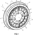
- the Figure 1 presents four noise-absorbing devices 1 also called anti-squeal devices fixed on a wheel 3 of a railway vehicle.
- the railway vehicle is for example a metro, a tramway or any other rail vehicle carrying passengers or freight.
- the wheel 3 of axis XX comprises a tire 5 delimiting a tread 7 in contact with the surface of the top of the rail (not shown) and a lateral bead 9, which guards the wheel 3 by bearing on the face Lateral rail.
- the lateral bead 9 projects radially and is oriented towards the inside of the rails.
- the wheel 3 further comprises a hub 11 and is fixed to an axle or a rocket, either by setting or by bolting (not shown).
- the sound absorbing device 1, shown on the Figure 2 has an annular sector shape.
- the noise absorbing device 1 comprises an outer blade 13A and an inner blade 13B which extend radially from a connecting end 15A, 15B fixed to the periphery of the wheel 3, to a free end 17A, 17B, directed towards the center of the wheel 3.
- the blades 13A, 13B extend in the plane of the wheel, i.e. perpendicular to the X-X axis of the wheel 3. They have an annular sector shape and are parallel to each other.
- Each of the blades 13A, 13B comprises an inner face and an outer face, the inner face of the blade 13A being positioned facing the outer face of the blade 13B.
- the device 1 further comprises damping masses 19A, 19B, 19C fixed on the inner and outer faces of the free ends 17A, 17B of the blades 13A, 13B, away from the connecting ends 15A, 15B.
- the device 1 comprises a first damping mass 19A fixed on the outer face of the free end 17A, a second damping mass 19B clamped between the inner face of the free end 17A and the outer face of the free end 17B and a third damping mass fixed on the inner face of the free end 17B.
- the fastening flange 23 comprises two lateral attachment flanges 25 between which the connecting ends 15A, 15B of the blades 13A, 13B are clamped together and an intermediate fixing flange 29.
- the intermediate fixing flange 29 makes it possible to maintain a constant spacing between the two blades 13A, 13B and in particular between the connecting ends 15A, 15B of the blades 13A, 13B.
- the fastening flange 23 comprises screw-receiving holes 31 for connection to the wheel 3.
- the free end 17A, 17B of the blades 13A, 13B extends radially towards the center of the wheel 3. It extends for example to the hub 11 of the wheel 3 without being in contact with the latter.
- each blade 13A, 13B comprises at least two metallic or composite layers 33 parallel to each other and at least one layer of viscoelastic material 35 disposed between said metal or composite layers 33.
- the two metal or composite layers 33 are adhered to the viscoelastic material layer 35 over their entire surface.
- the layers 33 are typically made of steel, aluminum, titanium or even composite material.
- the thickness of a layer 33 is dependent on the stiffness desired for the dynamic beater portion of the noise absorbing device.
- a viscoelastic material is a material that has rheological properties intermediate between an elastic solid and a viscous liquid.
- the behavior of such a material depends on a characteristic time associated with the stress or strain applied to the material. Thus, at short times, for example during an impact, the behavior of the material is elastic. In contrast to long times, the behavior of the material is viscous, for example when the material is subjected to a constant stress (creep).
- the viscoelastic material layer 35 is for example made of polymer.
- the thickness of the layer of viscoelastic material 35 is between 0.05 mm and 2 mm, preferably between 0.5 mm and 1.5 mm, typically equal to 0.5 mm.
- the blades 13A, 13B comprise at least one radial slot 37, visible on the Figure 1 extending at the free end 17A, 17B of said blades 13A, 13B. Each blade 13A, 13B then delimits, on either side of said radial slot 37, two radial branches 39.
- the blades 13A, 13B are devoid of radial slot 37.
- the blades 13A, 13B comprise three radial slots 37 defining four radial branches 39.
- the number of radial branches is greater than or less than four.
- the damping masses 19A, 19B, 19C have for example an annular sector shape and cover the entire surface of the free ends of the blades delimited by the radial slots 37, or at least 50% of the area of the free ends of the blades delimited by the radial slots 37.
- the radial surface of the blade in contact with the damping masses is greater than the radial surface of the blade in contact with the fixing flanges and also the radial surface of the annular space 43.
- the damping masses 19A, 19B, 19C are for example metal, typically steel.
- a plurality of fasteners 41 passes right through the damping masses 19A, 19B, 19C and the blades 13A, 13B to assemble them together.
- damping masses 19A, 19B, 19C are glued to the blade blades 13A, 13B.
- the thicknesses of the intermediate mass 19C and the intermediate fixing flange 29 are identical.
- damping masses 19A, 19B, 19C of each radial branch 39 advantageously have a different mass from one radial branch 39 to another.
- the damping mass 19A, 19B, 19C of each radial branch 39 has a different position on the free end 17A, 17B of the blade 13A, 13B of a radial branch 39 to another.
- damping masses 19A, 19B, 19C are fixed away from the connecting end 15A, 15B of the blades 13A, 13B and the fastening flange 23 thus releasing an annular space 43 of free movement of the blades 13A, 13B.
- the annular space 43 thus comprises two outer 43A and 43B inner grooves respectively opening outwardly and inwardly and delimited between the outer 19A and inner 19C masses, and the fixing flange 23.
- the outer blade 13A, the inner blade 13B, the intermediate fixing flange 29 and the intermediate mass 19B define a hollow annular space 45.
- the radial width of the annular space 43 of free movement is between 5 mm and 15 mm.
- the widths of the outer grooves 43A and inner 43B are for example identical.
- the widths of the outer grooves 43A and inner 43B are different.
- the noise-absorbing devices 1 are advantageously distributed over the periphery of the wheel 3 so that at least one passage 47 can be reserved, between the noise-absorbing devices 1, for the passage of shunt cables 49 connecting the tire 5 of the wheel 3 to the axle of the wheel 3.
- the wheel 3 here comprises four noise-absorbing devices 1 and four shunt cables 49.
- the noise absorbing devices 1 are typically fixed on the wheel 3 in a regular peripheral distribution with radial symmetry.
- the thickness of the blades 13A, 13B of each noise absorber device 1 of the wheel 3 is different from a noise absorber device 1 to another.
- the noise absorbing devices 1 are identical by radial symmetry.
- the number of shunt cables 49 and noise absorber devices 1 shown in FIG. figure 1 is given only as an example.
- the wheel 3 comprises, for example, a single noise absorber device 1, for example forming a closed ring.
- the wheel 3 comprises one or more shunt cables 49 disposed on one face of the wheel 3 opposite to that which receives the noise-absorbing devices 1.
- the number of shunt cables 49 is less than or greater than 4 and is, for example, zero.
- the noise absorber devices 1 are positioned on an inner face of the wheel 3 and not on an outer face of the wheel 3 as shown in FIG. figure 1 .
- the noise absorber devices 1 are positioned both on the inner face of the wheel 3 and on the outer face of the wheel 3.
- the absorber device 1 comprises a single blade or more than two blades, the number of damping masses then being adapted as a function of the number of blades.
- the blades 13A and 13B are contiguous to each other and the noise absorber device 1 is devoid of intermediate fixing plate 29 and advantageously also of the second damping mass 19B.
- the wheel 3 vibrates and causes squealing.
- the noise absorbing device 1 acts as a dynamic beater or dynamic absorber set to vibrate at a specific frequency which corresponds to a natural frequency of a mode of axial vibration of the wheel 3.
- the vibration frequency of the dynamic beater is proportional to the square root of the ratio between the stiffness K of the dynamic beater, which acts in a similar manner to a spring, and a mass M formed of the damping masses 19A, 19B, 19C.
- the stiffness K of the device 1 according to the invention depends in particular on the thickness of each of the blades 13A, 13B, the distance between the two blades 13A, 13B, and the width of the annular space 43 of free movement, ie the position of the damping masses 19A, 19B, 19C on the free end 17A, 17B of each of the blades 13A, 13B.
- Each radial branch 39 of the noise-absorbing device 1 thus acts as an independent dynamic beater and makes it possible to damp a specific frequency of the squeal of the wheel.
- the device 1 attenuates the eigenfrequencies related to the orders of the modes of the wheel 3 most impacted by the curl in curve.
- Frequencies associated with the upper wheel modes are processed by structural damping.
- the damping masses 19A, 19B, 19C fixed on the blades 13A, 13B vibrate relatively radially relatively to each other and shear the layers of viscoelastic material 35 of the blades 13A, 13B for the dissipation of energy.
- the noise-absorbing device 1 is particularly advantageous because it makes it possible to reduce the squeal of the wheel 3. In fact, it acts over a wide range of frequencies by coupling the advantages of damping by dynamic beater and shear damping of a viscoelastic layer
- the device according to the invention 1 also has the advantage of being able to be installed on existing equipment and to be dimensioned according to particular wheel modes.
- the noise absorber device comprises a single blade.
- the fixing flange then comprises only an outer fixing flange and a lower fixing flange which hold the blade fixed to the tire 5 of the wheel 3.
- the blade has a structure identical to that described above and the device then comprises two masses of damping fixed on each of the faces of the free end of the blade.
Description
La présente invention concerne un dispositif absorbeur de bruit pour une roue de véhicule ferroviaire, du type comprenant au moins une lame s'étendant radialement depuis une extrémité de liaison propre à être fixée à la périphérie de la roue, jusqu'à une extrémité libre, et au moins une masse d'amortissement fixée sur une face de l'extrémité libre de la lame, à l'écart de l'extrémité de liaison.The present invention relates to a noise absorber device for a railway vehicle wheel, of the type comprising at least one blade extending radially from a connection end adapted to be fixed at the periphery of the wheel, to a free end, and at least one damping mass fixed on one face of the free end of the blade, away from the connecting end.
Un tel dispositif est connu dans l'état de la technique sous le nom d'absorbeur dynamique ou batteur (voir pour exemple
Ce dispositif présente un inconvénient car il permet d'atténuer le crissement généré par les roues uniquement sur une bande de fréquences très étroite centrée sur la fréquence de résonance du batteur dynamique.This device has a disadvantage because it reduces the squeal generated by the wheels only on a very narrow frequency band centered on the resonant frequency of the dynamic beater.
Ainsi, même si on multiplie le nombre de batteurs dynamiques, seuls quelques modes de vibrations de roue sont amortis. Un batteur dynamique ne permet pas d'amortir les modes de vibration de la roue autres que ceux pour lesquels il est réglé.Thus, even if one multiplies the number of dynamic beaters, only some modes of wheel vibrations are damped. A dynamic beater does not dampen the vibration modes of the wheel other than those for which it is set.
Un objectif de l'invention est donc de proposer un dispositif absorbeur de bruit pour une roue de véhicule ferroviaire, capable d'atténuer le crissement sur une large gamme de fréquences à la fois autour des fréquences des modes vibratoires d'ordre faible mais également au niveau du contenu plus haute fréquence correspondant aux modes vibratoires d'ordres plus élevés.An object of the invention is therefore to provide a noise absorber device for a railway vehicle wheel, capable of attenuating squeal over a wide range of frequencies both around the frequencies of the low order vibration modes and also at the higher frequency content level corresponding to higher order vibratory modes.
A cet effet, l'invention a pour objet un dispositif absorbeur de bruit pour une roue de véhicule ferroviaire du type précité, caractérisé en ce que la lame comprend au moins deux couches métalliques et au moins une couche en matériau viscoélastique enserrée entre les deux couches métalliques.For this purpose, the invention relates to a noise absorber device for a railway vehicle wheel of the aforementioned type, characterized in that the blade comprises at least two metal layers and at least one layer of viscoelastic material sandwiched between the two layers metal.
Suivant des modes particuliers de réalisation, le dispositif absorbeur de bruit présente également une ou plusieurs des caractéristiques ci-dessous, considérées individuellement ou selon toutes les combinaisons techniquement possibles :
- la ou chaque lame comporte au moins une fente radiale s'étendant sur l'extrémité libre de la lame, la ou chaque fente radiale délimitant une pluralité de branche radiales, chaque branche radiale portant au moins une masse d'amortissement fixée sur son extrémité libre ;
- la ou chaque masse d'amortissement de chaque branche radiale a une masse différente et/ou une position différente sur l'extrémité libre de la lame, d'une branche radiale à une autre ;
- le dispositif comprend deux lames parallèles fixées entre elles au niveau de leurs extrémités de liaison, chaque lame comprenant au moins deux couches métalliques ou composites parallèles et au moins une couche en matériau viscoélastique enserrée entre les deux couches métalliques ou composites ;
- le dispositif a une forme de secteur annulaire ;
- l'épaisseur de la couche viscoélastique est comprise entre 0,05 mm et 2 mm ;
- la masse d'amortissement est fixée à l'écart de l'extrémité de liaison de la lame dégageant un espace annulaire de libre mouvement de la lame.
- the or each blade comprises at least one radial slot extending on the free end of the blade, the or each radial slot defining a plurality of radial branches, each radial branch carrying at least one damping mass fixed on its free end ;
- the or each damping mass of each radial branch has a different mass and / or a different position on the free end of the blade, from one radial branch to another;
- the device comprises two parallel blades fixed together at their connecting ends, each blade comprising at least two parallel metal layers or composites and at least one layer of viscoelastic material sandwiched between the two metal or composite layers;
- the device has an annular sector shape;
- the thickness of the viscoelastic layer is between 0.05 mm and 2 mm;
- the damping mass is fixed away from the connecting end of the blade releasing an annular space of free movement of the blade.
L'invention a également pour objet une roue pour véhicule ferroviaire comportant au moins un dispositif absorbeur de bruit tel que défini ci-dessus.The invention also relates to a wheel for a railway vehicle comprising at least one noise-absorbing device as defined above.
Suivant des modes particuliers de réalisation, la roue présente également une ou plusieurs des caractéristiques ci-dessous, considérées individuellement ou selon toutes les combinaisons techniquement possibles :
- la roue comporte une pluralité de dispositifs absorbeurs de bruit tels que définis ci-dessus et l'épaisseur de la lame d'au moins un des dispositifs absorbeurs de bruit est différente de celle d'un autre des dispositifs absorbeurs de bruit ;
- la roue comporte une pluralité de dispositifs absorbeurs de bruit tels que définis ci-dessus répartis sur la périphérie de la roue ;
- au moins un passage est réservé entre les dispositifs absorbeurs de bruit pour le passage de câbles de shunt.
- the wheel comprises a plurality of noise-absorbing devices as defined above and the thickness of the blade of at least one of the noise-absorbing devices is different from that of another of the noise-absorbing devices;
- the wheel comprises a plurality of noise-absorbing devices as defined above distributed over the periphery of the wheel;
- at least one passage is reserved between the noise-absorbing devices for the passage of shunt cables.
D'autres caractéristiques et avantages de l'invention ressortiront de la description détaillée qui va suivre, donnée à titre indicatif et nullement limitatif, en référence aux figures annexées, parmi lesquelles :
- la
Figure 1 est une vue en perspective d'une roue de véhicule ferroviaire selon l'invention, la roue comprenant quatre dispositifs absorbeurs de bruit, - la
Figure 2 est une vue en perspective de l'un des dispositifs absorbeur de bruit de laFigure 1 , - la
Figure 3 est une section radiale schématique du dispositif selon l'invention de laFigure 2 .
- the
Figure 1 is a perspective view of a railway vehicle wheel according to the invention, the wheel comprising four noise-absorbing devices, - the
Figure 2 is a perspective view of one of the noise absorber devices of theFigure 1 , - the
Figure 3 is a schematic radial section of the device according to the invention of theFigure 2 .
La
Le véhicule ferroviaire est par exemple un métro, un tramway ou tout autre véhicule sur rail transportant des passagers ou du fret.The railway vehicle is for example a metro, a tramway or any other rail vehicle carrying passengers or freight.
La roue 3 d'axe X-X comporte un bandage 5 délimitant une bande de roulement 7 en contact avec la surface du haut du rail (non représenté) et un boudin latéral 9, qui assure le guidage de la roue 3 en prenant appui sur la face latérale du rail. Le boudin latéral 9 fait saillie radialement et est orienté vers l'intérieur des rails. La roue 3 comporte en outre un moyeu 11 et est fixée à un essieu ou à une fusée, soit par calage, soit par boulonnage (non représenté).The wheel 3 of axis XX comprises a
Le dispositif absorbeur de bruit 1, représenté sur la
Le dispositif absorbeur de bruit 1 comporte une lame extérieure 13A et une lame intérieure 13B qui s'étendent radialement depuis une extrémité de liaison 15A, 15B fixée à la périphérie de la roue 3, jusqu'à une extrémité libre 17A, 17B, orientée vers le centre de la roue 3.The
Les lames 13A, 13B s'étendent dans le plan de la roue, i.e. perpendiculairement à l'axe X-X de la roue 3. Elles ont une forme de secteur annulaire et sont parallèles entre elles.The
Chacune des lames 13A, 13B comprend une face interne et une face externe, la face interne de la lame 13A étant positionnée en regard de la face externe de la lame 13B.Each of the
Le dispositif 1 comporte en outre des masses d'amortissement 19A, 19B, 19C fixées sur les faces internes et externes des extrémités libres 17A, 17B des lames 13A, 13B, à l'écart des extrémités de liaison 15A, 15B.The
Plus précisément le dispositif 1 comprend une première masse d'amortissement 19A fixée sur la face externe de l'extrémité libre 17A, une deuxième masse d'amortissement 19B enserrée entre la face interne de l'extrémité libre 17A et la face externe de l'extrémité libre 17B et une troisième masse d'amortissement fixée sur la face interne de l'extrémité libre 17B.More specifically, the
Une bride de fixation 23 ayant la forme d'une portion annulaire, comme visible sur la
La bride de fixation 23 comporte deux flasques de fixation latéraux 25 entre lesquels sont enserrées les extrémités de liaison 15A, 15B des lames 13A, 13B et un flasque de fixation intermédiaire 29.The
Le flasque de fixation intermédiaire 29 permet de maintenir un espacement constant entre les deux lames 13A, 13B et notamment entre les extrémités de liaison 15A, 15B des lames 13A, 13B.The
La bride de fixation 23 comporte des perçages de réception de vis 31 de liaison à la roue 3.The
L'extrémité libre 17A, 17B des lames 13A, 13B s'étend radialement vers le centre de la roue 3. Elle s'étend par exemple jusqu'au moyeu 11 de la roue 3 sans toutefois être en contact avec ce dernier.The
Comme visible sur la
Les deux couches métalliques ou composites 33 sont adhérisées à la couche de matériau viscoélastique 35 sur toute leur surface.The two metal or
Les couches 33 sont typiquement en acier, en aluminium, en titane, voire en matériau composite.The
L'épaisseur d'une couche 33 est dépendante de la raideur désirée pour la partie batteur dynamique du dispositif absorbeur de bruit.The thickness of a
Un matériau viscoélastique est un matériau qui possède des propriétés rhéologiques intermédiaires entre un solide élastique et un liquide visqueux. Le comportement d'un tel matériau dépend d'un temps caractéristique associé à la contrainte ou à la déformation appliquée sur le matériau. Ainsi, aux temps courts, par exemple lors d'un choc, le comportement du matériau est élastique. A l'inverse aux temps longs, le comportement du matériau est visqueux, par exemple lorsque le matériau est soumis à une contrainte constante (fluage).A viscoelastic material is a material that has rheological properties intermediate between an elastic solid and a viscous liquid. The behavior of such a material depends on a characteristic time associated with the stress or strain applied to the material. Thus, at short times, for example during an impact, the behavior of the material is elastic. In contrast to long times, the behavior of the material is viscous, for example when the material is subjected to a constant stress (creep).
La couche de matériau viscoélastique 35 est par exemple en polymère.The
Avantageusement, l'épaisseur de la couche en matériau viscoélastique 35 est comprise entre 0,05 mm et 2 mm, de préférence entre 0,5 mm et 1,5 mm, typiquement égale à 0,5 mm.Advantageously, the thickness of the layer of
Les lames 13A, 13B comportent au moins une fente radiale 37, visible sur la
En variante, les lames 13A, 13B sont dépourvues de fente radiale 37.Alternatively, the
Dans l'exemple de la
En variante, le nombre de branches radiales est supérieur ou inférieur à quatre.As a variant, the number of radial branches is greater than or less than four.
Les masses d'amortissement 19A, 19B, 19C ont par exemple une forme de secteur annulaire et recouvrent toute la surface des extrémités libres des lames délimitées par les fentes radiales 37, ou au moins 50% de la surface des extrémités libres des lames délimitées par les fentes radiales 37.The damping
Plus généralement, avantageusement, pour chaque lame, la surface radiale de la lame en contact avec les masses d'amortissement est supérieure à la surface radiale de la lame en contact avec les flasques de fixation et également à la surface radiale de l'espace annulaire 43.More generally, advantageously, for each blade, the radial surface of the blade in contact with the damping masses is greater than the radial surface of the blade in contact with the fixing flanges and also the radial surface of the
Les masses d'amortissement 19A, 19B, 19C sont par exemple en métal, typiquement en acier.The damping
Une pluralité d'organes de fixation 41 traverse de part en part les masses d'amortissement 19A, 19B, 19C et les lames 13A, 13B pour les assembler ensemble.A plurality of
En variante, les masses d'amortissement 19A, 19B, 19C sont collées sur les lames lame 13A, 13B.Alternatively, the damping
Typiquement, les épaisseurs de la masse intermédiaire 19C et du flasque de fixation intermédiaire 29 sont identiques.Typically, the thicknesses of the
Les masses d'amortissement 19A, 19B, 19C de chaque branche radiale 39 ont avantageusement une masse différente d'une branche radiale 39 à une autre.The damping
Avantageusement, la masse d'amortissement 19A, 19B, 19C de chaque branche radiale 39 a une position différente sur l'extrémité libre 17A, 17B de la lame 13A, 13B d'une branche radiale 39 à une autre.Advantageously, the damping
Les masses d'amortissement 19A, 19B, 19C sont fixées à l'écart de l'extrémité de liaison 15A, 15B des lames 13A, 13B et de la bride de fixation 23 dégageant ainsi un espace annulaire 43 de libre mouvement des lames 13A, 13B.The damping
L'espace annulaire 43 comporte ainsi deux gorges extérieure 43A et intérieure 43B s'ouvrant respectivement vers l'extérieur et l'intérieur et délimitées entre les masses extérieure 19A et intérieure 19C, et la bride de fixation 23.The
La lame extérieure 13A, la lame intérieure 13B, le flasque de fixation intermédiaire 29 et la masse intermédiaire 19B délimitent un espace annulaire 45 creux.The
La largeur radiale de l'espace annulaire 43 de libre mouvement est comprise entre 5mm et 15 mm.The radial width of the
Les largeurs des gorges extérieure 43A et intérieure 43B sont par exemple identiques.The widths of the
Selon un mode de réalisation non représentée, les largeurs des gorges extérieure 43A et intérieure 43B sont différentes.According to an embodiment not shown, the widths of the
Comme visible sur la
La roue 3 comporte ici quatre dispositifs absorbeurs de bruit 1 et quatre câbles de shunt 49.The wheel 3 here comprises four noise-absorbing
Les dispositifs absorbeurs de bruit 1 sont typiquement fixés sur la roue 3 selon une répartition périphérique régulière à symétrie radiale.The
Avantageusement, l'épaisseur des lames 13A, 13B de chaque dispositif absorbeur de bruit 1 de la roue 3 est différente d'un dispositif absorbeur de bruit 1 à un autre.Advantageously, the thickness of the
Avantageusement encore, les dispositifs absorbeurs de bruit 1 sont identiques par symétrie radiale.Advantageously, the
Le nombre de câbles de shunt 49 et de dispositifs absorbeur de bruit 1 représentés à la
En variante, la roue 3 comprend par exemple un unique dispositif absorbeur de bruit 1, par exemple formant un anneau fermé.As a variant, the wheel 3 comprises, for example, a single
Selon une autre variante, la roue 3 comprend un ou plusieurs câbles de shunt 49 disposés sur une face de la roue 3 opposée à celle qui reçoit les dispositifs absorbeurs de bruit 1.According to another variant, the wheel 3 comprises one or
Selon une autre variante, le nombre de câbles de shunt 49 est inférieur ou supérieur à 4 et est, par exemple, nul.According to another variant, the number of
Selon une autre variante, les dispositifs absorbeurs de bruit 1 sont positionnés sur une face interne de la roue 3 et non sur une face externe de la roue 3 comme représenté à la
Selon une autre variante, les dispositifs absorbeurs de bruit 1 sont positionnés à la fois sur la face interne de la roue 3 et sur la face externe de la roue 3.According to another variant, the
Selon une autre variante le dispositif absorbeur 1 comprend une seule lame ou plus de deux lames, le nombre de masses d'amortissement étant alors adapté en fonction du nombre de lames.According to another variant, the
Selon une autre variante, les lames 13A et 13B sont accolées l'une à l'autre et le dispositif absorbeur de bruit 1 est dépourvu de flasque de fixation intermédiaire 29 et avantageusement également de la deuxième masse d'amortissement 19B.According to another variant, the
Le fonctionnement du dispositif absorbeur de bruit 1 selon l'invention va maintenant être décrit.The operation of the
Sous l'effet des efforts engendrés par le roulement sur un rail, et plus particulièrement dans les courbes de faible rayon, la roue 3 entre en vibration et provoque un crissement.Under the effect of the forces generated by the rolling on a rail, and more particularly in the curves of small radius, the wheel 3 vibrates and causes squealing.
Le dispositif absorbeur de bruit 1 selon l'invention agit comme un batteur dynamique ou absorbeur dynamique réglé pour vibrer à une fréquence spécifique qui correspond à une fréquence propre d'un mode de vibration axial de la roue 3.The
La fréquence de vibration du batteur dynamique est proportionnelle à la racine carrée du rapport entre la raideur K du batteur dynamique, qui agit de manière analogue à un ressort, et une masse M formée des masses d'amortissement 19A, 19B, 19C.The vibration frequency of the dynamic beater is proportional to the square root of the ratio between the stiffness K of the dynamic beater, which acts in a similar manner to a spring, and a mass M formed of the damping
La raideur K du dispositif 1 selon l'invention dépend notamment de l'épaisseur de chacune des lames 13A, 13B, de la distance entre les deux lames 13A, 13B, et de la largeur de l'espace annulaire 43 de libre mouvement, i.e. de la position des masses d'amortissement 19A, 19B, 19C sur l'extrémité libre 17A, 17B de chacune des lames 13A, 13B.The stiffness K of the
Chaque branche radiale 39 du dispositif absorbeur de bruit 1 agit ainsi comme un batteur dynamique indépendant et permet d'amortir une fréquence spécifique du crissement de la roue.Each
Ainsi, le dispositif 1 atténue les fréquences propres liées aux ordres des modes de la roue 3 les plus impactés par le crissement en courbe.Thus, the
Les fréquences associées aux modes de roue supérieurs (fréquences plus élevées) sont traitées par de l'amortissement structural. Les masses d'amortissement 19A, 19B, 19C fixées sur les lames 13A, 13B vibrent radialement relativement les unes par rapport aux autres et cisaillent les couches de matériau viscoélastique 35 des lame 13A, 13B permettant la dissipation d'énergie.Frequencies associated with the upper wheel modes (higher frequencies) are processed by structural damping. The damping
Ainsi, le dispositif absorbeur de bruit 1 selon l'invention est particulièrement avantageux car il permet de réduire le crissement de la roue 3. En effet, il agit sur une large gamme de fréquences en couplant les avantages de l'amortissement par batteur dynamique et de l'amortissement par cisaillement d'une couche viscoélastiqueThus, the noise-absorbing
Le dispositif selon l'invention 1 présente également l'avantage de pouvoir être installé sur du matériel existant et d'être dimensionné en fonction des modes de roue particuliers.The device according to the
Dans un mode de réalisation non représenté, le dispositif absorbeur de bruit comporte une seule lame. La bride de fixation comporte alors uniquement un flasque de fixation extérieur et un flasque de fixation inférieur qui maintiennent la lame fixée au bandage 5 de la roue 3.In an embodiment not shown, the noise absorber device comprises a single blade. The fixing flange then comprises only an outer fixing flange and a lower fixing flange which hold the blade fixed to the
La lame comporte une structure identique à ce qui a été décrit précédemment et le dispositif comporte alors deux masses d'amortissements fixées sur chacune des faces de l'extrémité libre de la lame.The blade has a structure identical to that described above and the device then comprises two masses of damping fixed on each of the faces of the free end of the blade.
Les modes de réalisation et variantes envisagés ci-dessus sont propres à être combinés entre eux pour donner lieu à d'autres modes de réalisation de l'invention.The embodiments and variants envisaged above are suitable for being combined with one another to give rise to other embodiments of the invention.
Claims (11)
- A noise-absorbing device (1) for a railway vehicle wheel, comprising:- at least one strip (13A, 13B) extending radially from a connecting end (15A, 15B) capable of being fastened to the periphery of the wheel (3), to a free end (17A, 17B),- at least one damping mass (19A, 19B, 19C) fastened on a face of the free end (17A, 17B) of the strip, away from the connecting end (15A, 15B),characterized in that the strip (13A, 13B) includes at least two metal or composite layers (33) and at least one layer of viscoelastic material (35) gripped between the two metal or composite layers (33).
- The noise-absorbing device (1) according to claim 1, characterized in that the or each strip (13A, 13B) comprises at least one radial slit (37) extending over the free end (17A, 17B) of the strip (13A, 13B), the or each radial slit (37) delimiting a plurality of radial branches (39), each radial branch (39) bearing at least one damping mass (19A, 19B, 19C) fastened on its free end (17A, 17B).
- The noise-absorbing device (1) according to claim 2, characterized in that the or each damping mass (19A, 19B, 19C) of each radial branch (39) has a different mass and/or a different position on the free end (17A, 17B) of the strip (13A, 13B), from one radial branch (39) to another.
- The noise-absorbing device (1) according to any one of claims 1 to 3, characterized in that the device (1) includes two parallel strips (13A, 13B) fastened to one another at their connecting ends (15A, 15B), each strip (13A, 13B) including at least two parallel metal or composite layers (33) and at least one layer of viscoelastic material (35) gripped between the two metal or composite layers (33).
- The noise-absorbing device (1) according to any one of the preceding claims, characterized in that the device (1) is in the form of an annular sector.
- The noise-absorbing device (1) according to any one of the preceding claims, characterized in that the thickness of the viscoelastic layer (35) is comprised between 0.05 mm and 2 mm.
- The noise-absorbing device (1) according to any one of the preceding claims, characterized in that the damping mass (19A, 19B, 19C) is fastened away from the connecting end (15A, 15B) of the strip (13A, 13B), freeing an annular space (43) for free movement of the strip (13A, 13B).
- A wheel (3) for a railway vehicle comprising at least one noise-absorbing device (1) according to any one of the preceding claims.
- The wheel (3) for a railway vehicle according to claim 8, characterized in that the wheel comprises a plurality of noise-absorbing devices (1) according to any one of claims 1 to 7, and in that the thickness of the strip (13A, 13B) of at least one of the noise-absorbing devices (1) is different from that of another of the noise-absorbing devices (1).
- The wheel (3) for a railway vehicle according to claim 8 or 9, characterized in that the wheel comprises a plurality of noise-absorbing devices (1) according to any one of claims 1 to 7, distributed on the periphery of the wheel (3).
- The wheel (3) for a railway vehicle according to claim 10, characterized in that at least one passage (47) is reserved between the noise-absorbing devices (1) for the passage of shunt cables (49).
Priority Applications (1)
| Application Number | Priority Date | Filing Date | Title |
|---|---|---|---|
| PL18195733T PL3459760T3 (en) | 2017-09-20 | 2018-09-20 | Noise absorber device for railway vehicle wheel and associated railway vehicle wheel |
Applications Claiming Priority (1)
| Application Number | Priority Date | Filing Date | Title |
|---|---|---|---|
| FR1758721A FR3071193B1 (en) | 2017-09-20 | 2017-09-20 | NOISE ABSORBER DEVICE FOR RAILWAY VEHICLE WHEEL AND ASSOCIATED RAILWAY VEHICLE WHEEL |
Publications (2)
| Publication Number | Publication Date |
|---|---|
| EP3459760A1 EP3459760A1 (en) | 2019-03-27 |
| EP3459760B1 true EP3459760B1 (en) | 2019-11-27 |
Family
ID=60202209
Family Applications (1)
| Application Number | Title | Priority Date | Filing Date |
|---|---|---|---|
| EP18195733.3A Active EP3459760B1 (en) | 2017-09-20 | 2018-09-20 | Noise absorber device for railway vehicle wheel and associated railway vehicle wheel |
Country Status (12)
| Country | Link |
|---|---|
| US (1) | US10933688B2 (en) |
| EP (1) | EP3459760B1 (en) |
| CN (1) | CN109515060B (en) |
| CA (1) | CA3018004A1 (en) |
| CO (1) | CO2018009923A1 (en) |
| DK (1) | DK3459760T3 (en) |
| ES (1) | ES2767697T3 (en) |
| FR (1) | FR3071193B1 (en) |
| HU (1) | HUE048294T2 (en) |
| IL (1) | IL261854B (en) |
| PE (1) | PE20190546A1 (en) |
| PL (1) | PL3459760T3 (en) |
Families Citing this family (2)
| Publication number | Priority date | Publication date | Assignee | Title |
|---|---|---|---|---|
| CN110641226B (en) * | 2019-10-25 | 2022-07-29 | 株洲时代新材料科技股份有限公司 | Elastic wheel noise reduction damper and assembling and mounting method thereof |
| AT523426B1 (en) * | 2020-04-02 | 2021-08-15 | Siemens Mobility Austria Gmbh | Soundproofing device for vehicle wheels |
Family Cites Families (34)
| Publication number | Priority date | Publication date | Assignee | Title |
|---|---|---|---|---|
| US3377097A (en) * | 1966-06-23 | 1968-04-09 | Goodrich Co B F | Vibration damped railway wheel |
| DE2652874C3 (en) * | 1976-11-20 | 1980-07-31 | Messerschmitt-Boelkow-Blohm Gmbh, 8000 Muenchen | Device for soundproofing on a rail wheel |
| DE2816561C3 (en) * | 1978-04-17 | 1981-10-15 | Krupp Stahl Ag, 4630 Bochum | System of rail wheel and track for rail vehicles |
| DE2835020C2 (en) * | 1978-08-10 | 1983-10-20 | Krupp Stahl Ag, 4630 Bochum | Vibration damper |
| DE2922585B1 (en) * | 1979-06-02 | 1980-12-11 | Krupp Ag Huettenwerke | Vibration absorber for resonance vibrations of rotating bodies |
| DE3033246C2 (en) * | 1980-09-04 | 1983-02-03 | Krupp Stahl Ag, 4630 Bochum | Vibration-dampened rail wheel |
| DE3119497C2 (en) * | 1981-05-15 | 1983-06-30 | M.A.N. Maschinenfabrik Augsburg-Nürnberg AG, 4200 Oberhausen | "Structure-borne silencer for an impeller" |
| DE3704506A1 (en) * | 1987-02-13 | 1988-08-25 | Hoesch Stahl Ag | COMPOSITE FOR VIBRATION DAMPING AND BODY SOUND DAMPING |
| FR2664667B1 (en) * | 1990-07-12 | 1993-07-16 | Barca Didier | VIBRATION DAMPING DEVICE. |
| DE19509389C1 (en) * | 1995-03-15 | 1996-08-14 | Daimler Benz Aerospace Ag | Body silencer for running wheels |
| FR2750650B1 (en) * | 1996-07-03 | 1998-11-06 | Valdunes | METHOD FOR SOUNDPROOFING A RAILWAY WHEEL AND SOUNDPROOFED RAILWAY WHEEL |
| US6402044B1 (en) * | 1997-02-03 | 2002-06-11 | Yugen Kaisha Koshinsha | Method of damping railroad noise and railroad noise damping members |
| NL1008966C2 (en) * | 1998-04-22 | 1999-10-25 | Skf Eng & Res Centre Bv | Railway vehicle wheel with improved damping properties. |
| DE10115370A1 (en) * | 2001-03-28 | 2002-10-10 | Ina Schaeffler Kg | Damper for metal wheels running on rails, is based on polytetrafluoroethylene material |
| CN100413712C (en) * | 2003-09-30 | 2008-08-27 | 尹学军 | Vehicle wheel |
| DE202006012852U1 (en) * | 2006-08-22 | 2006-10-26 | Gutehoffnungshütte Radsatz Gmbh | Sound absorber element for body sound attenuation in a rail vehicle wheel comprises at least two parallel absorber plates of which at least one is divided into tongue-like sections by at least one slit |
| JP5357242B2 (en) * | 2008-04-03 | 2013-12-04 | タイヤ・アコーステイクス・エル・エル・シー | Apparatus and system for reducing tire and wheel noise |
| JP2010083470A (en) * | 2008-09-03 | 2010-04-15 | Railway Technical Res Inst | Soundproof cover of wheel for railroad vehicle |
| AT508041A1 (en) * | 2009-03-16 | 2010-10-15 | Siemens Ag Oesterreich | RAIL VEHICLE WITH WHEEL ABSORBER |
| CN101712259B (en) * | 2009-11-13 | 2011-07-27 | 西南交通大学 | Noise-reduction damping device of train wheel |
| CN102041754A (en) * | 2010-12-27 | 2011-05-04 | 淄博正邦知识产权企划有限公司 | Shock-absorbing track |
| ITBS20120124A1 (en) * | 2012-07-30 | 2014-01-31 | Lucchini Rs Spa | RAILWHEEL AND RELATIVE SUSPENSION ELEMENT |
| WO2014131676A1 (en) * | 2013-02-28 | 2014-09-04 | Siemens Ag Österreich | Sound-damped wheel for rail vehicles |
| JP6004085B2 (en) * | 2013-03-28 | 2016-10-05 | 新日鐵住金株式会社 | Soundproof wheels for railway vehicles |
| CZ2013798A3 (en) * | 2013-10-17 | 2015-02-04 | Bonatrans Group A.S. | Vibration and noise damper |
| TWI581986B (en) * | 2014-07-24 | 2017-05-11 | Nippon Steel & Sumitomo Metal Corp | Railway vehicles with sound insulation wheels |
| US9545820B2 (en) * | 2014-10-31 | 2017-01-17 | GM Global Technology Operations LLC | Wheel with aluminum foam for tire cavity noise suppression |
| EP3075566A1 (en) * | 2015-04-02 | 2016-10-05 | Gutehoffnungshütte Radsatz GmbH | Elastic wheel for a rail vehicle |
| CN104972827A (en) * | 2015-07-13 | 2015-10-14 | 西南交通大学 | Train damping wheel |
| CN105564145A (en) * | 2016-01-08 | 2016-05-11 | 大连理工大学 | High-frequency noise reduction restraining and damping wheel containing slits |
| CN105922817B (en) * | 2016-04-21 | 2018-06-29 | 同济大学 | A kind of compound vibration damping and noise reducing device of city rail vehicle wheel |
| CN106004229A (en) * | 2016-07-19 | 2016-10-12 | 哈尔滨通达工业环保自动化有限公司 | Multilayered damper for wheel and damping method |
| CN106004226A (en) * | 2016-07-19 | 2016-10-12 | 哈尔滨通达工业环保自动化有限公司 | Constraint damping ring for wheel |
| CN106364256A (en) * | 2016-11-30 | 2017-02-01 | 西南交通大学 | Elastic wheel for subway vehicle |
-
2017
- 2017-09-20 FR FR1758721A patent/FR3071193B1/en not_active Expired - Fee Related
-
2018
- 2018-09-19 IL IL261854A patent/IL261854B/en unknown
- 2018-09-19 US US16/135,141 patent/US10933688B2/en active Active
- 2018-09-19 CA CA3018004A patent/CA3018004A1/en active Pending
- 2018-09-20 EP EP18195733.3A patent/EP3459760B1/en active Active
- 2018-09-20 CN CN201811102582.9A patent/CN109515060B/en active Active
- 2018-09-20 DK DK18195733.3T patent/DK3459760T3/en active
- 2018-09-20 HU HUE18195733A patent/HUE048294T2/en unknown
- 2018-09-20 PE PE2018001849A patent/PE20190546A1/en unknown
- 2018-09-20 CO CONC2018/0009923A patent/CO2018009923A1/en unknown
- 2018-09-20 ES ES18195733T patent/ES2767697T3/en active Active
- 2018-09-20 PL PL18195733T patent/PL3459760T3/en unknown
Non-Patent Citations (1)
| Title |
|---|
| None * |
Also Published As
| Publication number | Publication date |
|---|---|
| IL261854A (en) | 2019-02-28 |
| ES2767697T3 (en) | 2020-06-18 |
| CN109515060B (en) | 2023-07-07 |
| CA3018004A1 (en) | 2019-03-20 |
| BR102018069078A2 (en) | 2019-04-16 |
| EP3459760A1 (en) | 2019-03-27 |
| FR3071193A1 (en) | 2019-03-22 |
| US10933688B2 (en) | 2021-03-02 |
| IL261854B (en) | 2021-07-29 |
| CO2018009923A1 (en) | 2019-09-30 |
| CN109515060A (en) | 2019-03-26 |
| DK3459760T3 (en) | 2020-02-17 |
| PE20190546A1 (en) | 2019-04-16 |
| HUE048294T2 (en) | 2020-07-28 |
| FR3071193B1 (en) | 2019-10-18 |
| PL3459760T3 (en) | 2020-06-15 |
| US20190084347A1 (en) | 2019-03-21 |
Similar Documents
| Publication | Publication Date | Title |
|---|---|---|
| EP3459760B1 (en) | Noise absorber device for railway vehicle wheel and associated railway vehicle wheel | |
| EP3026295B1 (en) | Device for damping torsional oscillations | |
| EP3489487B1 (en) | Acoustic attenuation panel for aircraft | |
| EP3380750B1 (en) | Pendulum damping device | |
| EP2753851B1 (en) | Pinion vibration damping using viscoelastic patch | |
| FR2491545A1 (en) | BANDAGE FOR THE RADIAL CLAMPING OF SEGMENTS OF A SEGMENTED TURBINE FIN WHEEL | |
| EP3918227B1 (en) | Pendular damping device | |
| FR3043157A1 (en) | TORSION OSCILLATION DAMPING DEVICE | |
| FR2627545A1 (en) | INSULATION BUSHING FOR STRUCTURAL NOISE, ESPECIALLY BUSHING FOR INTERNAL COMBUSTION ENGINES | |
| EP0749853B1 (en) | Device for sound damping of a wheel, in particular of a motor vehicle | |
| FR2752278A1 (en) | STOP PIN AND POWER TRANSMISSION DEVICE | |
| EP0816126B1 (en) | Method for sound-damping of a railway wheel and sound damped railway wheel | |
| EP1568913B1 (en) | Vibration damper for disc brakes | |
| FR3057326B1 (en) | INERTIA WHEEL FOR VEHICLE TRANSMISSION SYSTEM | |
| BE1013240A6 (en) | Device support for rail rail. | |
| FR2929639A1 (en) | ROTOR BLADE | |
| EP3469229B1 (en) | Friction disk with pendular damping device | |
| FR3088397A1 (en) | PENDULUM DAMPING DEVICE | |
| FR3075298A1 (en) | PENDULAR DAMPING DEVICE HAVING A FALL ARREST SYSTEM | |
| FR3079010A1 (en) | PENDULAR DAMPING DEVICE | |
| FR3029254A1 (en) | TORSION OSCILLATION DAMPING DEVICE | |
| FR3069604B1 (en) | ASSUPLIED PENDULUM DAMPING DEVICE | |
| WO2015049433A1 (en) | Clutch disc device | |
| FR2847630A1 (en) | Torsional oscillations reducing device for vehicle, has limiting components and spinner, each including cut that forms cavity to receive damping part, leaf spring in cavity to transform peripheral movement of part into radial movement | |
| FR3031558A1 (en) | CLUTCH FRICTION DEVICE AND ITS USE IN A TRANSMISSION SYSTEM FOR A MOTOR VEHICLE |
Legal Events
| Date | Code | Title | Description |
|---|---|---|---|
| PUAI | Public reference made under article 153(3) epc to a published international application that has entered the european phase |
Free format text: ORIGINAL CODE: 0009012 |
|
| STAA | Information on the status of an ep patent application or granted ep patent |
Free format text: STATUS: THE APPLICATION HAS BEEN PUBLISHED |
|
| AK | Designated contracting states |
Kind code of ref document: A1 Designated state(s): AL AT BE BG CH CY CZ DE DK EE ES FI FR GB GR HR HU IE IS IT LI LT LU LV MC MK MT NL NO PL PT RO RS SE SI SK SM TR |
|
| AX | Request for extension of the european patent |
Extension state: BA ME |
|
| STAA | Information on the status of an ep patent application or granted ep patent |
Free format text: STATUS: REQUEST FOR EXAMINATION WAS MADE |
|
| 17P | Request for examination filed |
Effective date: 20190321 |
|
| RAV | Requested validation state of the european patent: fee paid |
Extension state: MA Effective date: 20190321 |
|
| RBV | Designated contracting states (corrected) |
Designated state(s): AL AT BE BG CH CY CZ DE DK EE ES FI FR GB GR HR HU IE IS IT LI LT LU LV MC MK MT NL NO PL PT RO RS SE SI SK SM TR |
|
| GRAP | Despatch of communication of intention to grant a patent |
Free format text: ORIGINAL CODE: EPIDOSNIGR1 |
|
| RIC1 | Information provided on ipc code assigned before grant |
Ipc: B60B 17/00 20060101AFI20190520BHEP |
|
| STAA | Information on the status of an ep patent application or granted ep patent |
Free format text: STATUS: GRANT OF PATENT IS INTENDED |
|
| INTG | Intention to grant announced |
Effective date: 20190627 |
|
| GRAS | Grant fee paid |
Free format text: ORIGINAL CODE: EPIDOSNIGR3 |
|
| GRAA | (expected) grant |
Free format text: ORIGINAL CODE: 0009210 |
|
| STAA | Information on the status of an ep patent application or granted ep patent |
Free format text: STATUS: THE PATENT HAS BEEN GRANTED |
|
| AK | Designated contracting states |
Kind code of ref document: B1 Designated state(s): AL AT BE BG CH CY CZ DE DK EE ES FI FR GB GR HR HU IE IS IT LI LT LU LV MC MK MT NL NO PL PT RO RS SE SI SK SM TR |
|
| REG | Reference to a national code |
Ref country code: GB Ref legal event code: FG4D Free format text: NOT ENGLISH |
|
| REG | Reference to a national code |
Ref country code: CH Ref legal event code: EP |
|
| REG | Reference to a national code |
Ref country code: AT Ref legal event code: REF Ref document number: 1206236 Country of ref document: AT Kind code of ref document: T Effective date: 20191215 |
|
| REG | Reference to a national code |
Ref country code: DE Ref legal event code: R096 Ref document number: 602018001387 Country of ref document: DE |
|
| REG | Reference to a national code |
Ref country code: IE Ref legal event code: FG4D Free format text: LANGUAGE OF EP DOCUMENT: FRENCH |
|
| REG | Reference to a national code |
Ref country code: CH Ref legal event code: NV Representative=s name: MICHELI AND CIE SA, CH |
|
| REG | Reference to a national code |
Ref country code: FI Ref legal event code: FGE |
|
| REG | Reference to a national code |
Ref country code: DK Ref legal event code: T3 Effective date: 20200212 |
|
| REG | Reference to a national code |
Ref country code: RO Ref legal event code: EPE |
|
| REG | Reference to a national code |
Ref country code: SE Ref legal event code: TRGR |
|
| REG | Reference to a national code |
Ref country code: LT Ref legal event code: MG4D |
|
| PG25 | Lapsed in a contracting state [announced via postgrant information from national office to epo] |
Ref country code: LV Free format text: LAPSE BECAUSE OF FAILURE TO SUBMIT A TRANSLATION OF THE DESCRIPTION OR TO PAY THE FEE WITHIN THE PRESCRIBED TIME-LIMIT Effective date: 20191127 Ref country code: LT Free format text: LAPSE BECAUSE OF FAILURE TO SUBMIT A TRANSLATION OF THE DESCRIPTION OR TO PAY THE FEE WITHIN THE PRESCRIBED TIME-LIMIT Effective date: 20191127 Ref country code: BG Free format text: LAPSE BECAUSE OF FAILURE TO SUBMIT A TRANSLATION OF THE DESCRIPTION OR TO PAY THE FEE WITHIN THE PRESCRIBED TIME-LIMIT Effective date: 20200227 Ref country code: GR Free format text: LAPSE BECAUSE OF FAILURE TO SUBMIT A TRANSLATION OF THE DESCRIPTION OR TO PAY THE FEE WITHIN THE PRESCRIBED TIME-LIMIT Effective date: 20200228 Ref country code: NO Free format text: LAPSE BECAUSE OF FAILURE TO SUBMIT A TRANSLATION OF THE DESCRIPTION OR TO PAY THE FEE WITHIN THE PRESCRIBED TIME-LIMIT Effective date: 20200227 |
|
| REG | Reference to a national code |
Ref country code: NL Ref legal event code: FP |
|
| PG25 | Lapsed in a contracting state [announced via postgrant information from national office to epo] |
Ref country code: RS Free format text: LAPSE BECAUSE OF FAILURE TO SUBMIT A TRANSLATION OF THE DESCRIPTION OR TO PAY THE FEE WITHIN THE PRESCRIBED TIME-LIMIT Effective date: 20191127 Ref country code: HR Free format text: LAPSE BECAUSE OF FAILURE TO SUBMIT A TRANSLATION OF THE DESCRIPTION OR TO PAY THE FEE WITHIN THE PRESCRIBED TIME-LIMIT Effective date: 20191127 Ref country code: IS Free format text: LAPSE BECAUSE OF FAILURE TO SUBMIT A TRANSLATION OF THE DESCRIPTION OR TO PAY THE FEE WITHIN THE PRESCRIBED TIME-LIMIT Effective date: 20200327 |
|
| REG | Reference to a national code |
Ref country code: ES Ref legal event code: FG2A Ref document number: 2767697 Country of ref document: ES Kind code of ref document: T3 Effective date: 20200618 |
|
| PG25 | Lapsed in a contracting state [announced via postgrant information from national office to epo] |
Ref country code: AL Free format text: LAPSE BECAUSE OF FAILURE TO SUBMIT A TRANSLATION OF THE DESCRIPTION OR TO PAY THE FEE WITHIN THE PRESCRIBED TIME-LIMIT Effective date: 20191127 |
|
| REG | Reference to a national code |
Ref country code: HU Ref legal event code: AG4A Ref document number: E048294 Country of ref document: HU |
|
| PG25 | Lapsed in a contracting state [announced via postgrant information from national office to epo] |
Ref country code: PT Free format text: LAPSE BECAUSE OF FAILURE TO SUBMIT A TRANSLATION OF THE DESCRIPTION OR TO PAY THE FEE WITHIN THE PRESCRIBED TIME-LIMIT Effective date: 20200419 Ref country code: EE Free format text: LAPSE BECAUSE OF FAILURE TO SUBMIT A TRANSLATION OF THE DESCRIPTION OR TO PAY THE FEE WITHIN THE PRESCRIBED TIME-LIMIT Effective date: 20191127 |
|
| REG | Reference to a national code |
Ref country code: DE Ref legal event code: R097 Ref document number: 602018001387 Country of ref document: DE |
|
| PG25 | Lapsed in a contracting state [announced via postgrant information from national office to epo] |
Ref country code: SM Free format text: LAPSE BECAUSE OF FAILURE TO SUBMIT A TRANSLATION OF THE DESCRIPTION OR TO PAY THE FEE WITHIN THE PRESCRIBED TIME-LIMIT Effective date: 20191127 Ref country code: SK Free format text: LAPSE BECAUSE OF FAILURE TO SUBMIT A TRANSLATION OF THE DESCRIPTION OR TO PAY THE FEE WITHIN THE PRESCRIBED TIME-LIMIT Effective date: 20191127 |
|
| PLBE | No opposition filed within time limit |
Free format text: ORIGINAL CODE: 0009261 |
|
| STAA | Information on the status of an ep patent application or granted ep patent |
Free format text: STATUS: NO OPPOSITION FILED WITHIN TIME LIMIT |
|
| 26N | No opposition filed |
Effective date: 20200828 |
|
| PG25 | Lapsed in a contracting state [announced via postgrant information from national office to epo] |
Ref country code: SI Free format text: LAPSE BECAUSE OF FAILURE TO SUBMIT A TRANSLATION OF THE DESCRIPTION OR TO PAY THE FEE WITHIN THE PRESCRIBED TIME-LIMIT Effective date: 20191127 |
|
| REG | Reference to a national code |
Ref country code: AT Ref legal event code: UEP Ref document number: 1206236 Country of ref document: AT Kind code of ref document: T Effective date: 20191127 |
|
| VS25 | Lapsed in a validation state [announced via postgrant information from nat. office to epo] |
Ref country code: MA Free format text: LAPSE BECAUSE OF FAILURE TO SUBMIT A TRANSLATION OF THE DESCRIPTION OR TO PAY THE FEE WITHIN THE PRESCRIBED TIME-LIMIT Effective date: 20191127 |
|
| PG25 | Lapsed in a contracting state [announced via postgrant information from national office to epo] |
Ref country code: LU Free format text: LAPSE BECAUSE OF NON-PAYMENT OF DUE FEES Effective date: 20200920 |
|
| PG25 | Lapsed in a contracting state [announced via postgrant information from national office to epo] |
Ref country code: IE Free format text: LAPSE BECAUSE OF NON-PAYMENT OF DUE FEES Effective date: 20200920 |
|
| PG25 | Lapsed in a contracting state [announced via postgrant information from national office to epo] |
Ref country code: MT Free format text: LAPSE BECAUSE OF FAILURE TO SUBMIT A TRANSLATION OF THE DESCRIPTION OR TO PAY THE FEE WITHIN THE PRESCRIBED TIME-LIMIT Effective date: 20191127 Ref country code: CY Free format text: LAPSE BECAUSE OF FAILURE TO SUBMIT A TRANSLATION OF THE DESCRIPTION OR TO PAY THE FEE WITHIN THE PRESCRIBED TIME-LIMIT Effective date: 20191127 |
|
| PG25 | Lapsed in a contracting state [announced via postgrant information from national office to epo] |
Ref country code: MK Free format text: LAPSE BECAUSE OF FAILURE TO SUBMIT A TRANSLATION OF THE DESCRIPTION OR TO PAY THE FEE WITHIN THE PRESCRIBED TIME-LIMIT Effective date: 20191127 Ref country code: MC Free format text: LAPSE BECAUSE OF FAILURE TO SUBMIT A TRANSLATION OF THE DESCRIPTION OR TO PAY THE FEE WITHIN THE PRESCRIBED TIME-LIMIT Effective date: 20191127 |
|
| PGFP | Annual fee paid to national office [announced via postgrant information from national office to epo] |
Ref country code: NL Payment date: 20230824 Year of fee payment: 6 |
|
| PGFP | Annual fee paid to national office [announced via postgrant information from national office to epo] |
Ref country code: TR Payment date: 20230918 Year of fee payment: 6 Ref country code: RO Payment date: 20230913 Year of fee payment: 6 Ref country code: IT Payment date: 20230911 Year of fee payment: 6 Ref country code: GB Payment date: 20230920 Year of fee payment: 6 Ref country code: FI Payment date: 20230821 Year of fee payment: 6 Ref country code: CZ Payment date: 20230821 Year of fee payment: 6 Ref country code: AT Payment date: 20230821 Year of fee payment: 6 |
|
| PGFP | Annual fee paid to national office [announced via postgrant information from national office to epo] |
Ref country code: SE Payment date: 20230922 Year of fee payment: 6 Ref country code: PL Payment date: 20230818 Year of fee payment: 6 Ref country code: HU Payment date: 20230922 Year of fee payment: 6 Ref country code: FR Payment date: 20230811 Year of fee payment: 6 Ref country code: DK Payment date: 20230824 Year of fee payment: 6 Ref country code: DE Payment date: 20230911 Year of fee payment: 6 Ref country code: BE Payment date: 20230914 Year of fee payment: 6 |
|
| P01 | Opt-out of the competence of the unified patent court (upc) registered |
Effective date: 20231027 |
|
| P04 | Withdrawal of opt-out of the competence of the unified patent court (upc) registered |
Effective date: 20231212 |
|
| PGFP | Annual fee paid to national office [announced via postgrant information from national office to epo] |
Ref country code: ES Payment date: 20231006 Year of fee payment: 6 |
|
| PGFP | Annual fee paid to national office [announced via postgrant information from national office to epo] |
Ref country code: CH Payment date: 20231001 Year of fee payment: 6 |
|
| P06 | Withdrawal of the competence of the unified patent court (upc) deleted | ||
| P03 | Opt-out of the competence of the unified patent court (upc) deleted |