EP3458635B1 - System zur inline-behandlung von faden - Google Patents
System zur inline-behandlung von faden Download PDFInfo
- Publication number
- EP3458635B1 EP3458635B1 EP17799776.4A EP17799776A EP3458635B1 EP 3458635 B1 EP3458635 B1 EP 3458635B1 EP 17799776 A EP17799776 A EP 17799776A EP 3458635 B1 EP3458635 B1 EP 3458635B1
- Authority
- EP
- European Patent Office
- Prior art keywords
- thread
- unit
- engagement device
- nozzle
- treatment unit
- Prior art date
- Legal status (The legal status is an assumption and is not a legal conclusion. Google has not performed a legal analysis and makes no representation as to the accuracy of the status listed.)
- Active
Links
Images


Classifications
-
- D—TEXTILES; PAPER
- D06—TREATMENT OF TEXTILES OR THE LIKE; LAUNDERING; FLEXIBLE MATERIALS NOT OTHERWISE PROVIDED FOR
- D06P—DYEING OR PRINTING TEXTILES; DYEING LEATHER, FURS OR SOLID MACROMOLECULAR SUBSTANCES IN ANY FORM
- D06P5/00—Other features in dyeing or printing textiles, or dyeing leather, furs, or solid macromolecular substances in any form
- D06P5/30—Ink jet printing
-
- D—TEXTILES; PAPER
- D05—SEWING; EMBROIDERING; TUFTING
- D05C—EMBROIDERING; TUFTING
- D05C11/00—Devices for guiding, feeding, handling, or treating the threads in embroidering machines; Machine needles; Operating or control mechanisms therefor
- D05C11/24—Devices for guiding, feeding, handling, or treating the threads in embroidering machines; Machine needles; Operating or control mechanisms therefor incorporating devices for dyeing or impregnating the threads
-
- D—TEXTILES; PAPER
- D03—WEAVING
- D03J—AUXILIARY WEAVING APPARATUS; WEAVERS' TOOLS; SHUTTLES
- D03J1/00—Auxiliary apparatus combined with or associated with looms
- D03J1/04—Auxiliary apparatus combined with or associated with looms for treating weft
-
- B—PERFORMING OPERATIONS; TRANSPORTING
- B05—SPRAYING OR ATOMISING IN GENERAL; APPLYING FLUENT MATERIALS TO SURFACES, IN GENERAL
- B05B—SPRAYING APPARATUS; ATOMISING APPARATUS; NOZZLES
- B05B1/00—Nozzles, spray heads or other outlets, with or without auxiliary devices such as valves, heating means
-
- B—PERFORMING OPERATIONS; TRANSPORTING
- B05—SPRAYING OR ATOMISING IN GENERAL; APPLYING FLUENT MATERIALS TO SURFACES, IN GENERAL
- B05B—SPRAYING APPARATUS; ATOMISING APPARATUS; NOZZLES
- B05B13/00—Machines or plants for applying liquids or other fluent materials to surfaces of objects or other work by spraying, not covered by groups B05B1/00 - B05B11/00
-
- B—PERFORMING OPERATIONS; TRANSPORTING
- B41—PRINTING; LINING MACHINES; TYPEWRITERS; STAMPS
- B41J—TYPEWRITERS; SELECTIVE PRINTING MECHANISMS, i.e. MECHANISMS PRINTING OTHERWISE THAN FROM A FORME; CORRECTION OF TYPOGRAPHICAL ERRORS
- B41J3/00—Typewriters or selective printing or marking mechanisms characterised by the purpose for which they are constructed
- B41J3/407—Typewriters or selective printing or marking mechanisms characterised by the purpose for which they are constructed for marking on special material
- B41J3/4078—Printing on textile
-
- D—TEXTILES; PAPER
- D04—BRAIDING; LACE-MAKING; KNITTING; TRIMMINGS; NON-WOVEN FABRICS
- D04B—KNITTING
- D04B1/00—Weft knitting processes for the production of fabrics or articles not dependent on the use of particular machines; Fabrics or articles defined by such processes
- D04B1/10—Patterned fabrics or articles
- D04B1/12—Patterned fabrics or articles characterised by thread material
- D04B1/126—Patterned fabrics or articles characterised by thread material with colour pattern, e.g. intarsia fabrics
-
- D—TEXTILES; PAPER
- D04—BRAIDING; LACE-MAKING; KNITTING; TRIMMINGS; NON-WOVEN FABRICS
- D04B—KNITTING
- D04B21/00—Warp knitting processes for the production of fabrics or articles not dependent on the use of particular machines; Fabrics or articles defined by such processes
- D04B21/06—Patterned fabrics or articles
-
- D—TEXTILES; PAPER
- D04—BRAIDING; LACE-MAKING; KNITTING; TRIMMINGS; NON-WOVEN FABRICS
- D04B—KNITTING
- D04B35/00—Details of, or auxiliary devices incorporated in, knitting machines, not otherwise provided for
- D04B35/22—Devices for preparatory treatment of threads
-
- D—TEXTILES; PAPER
- D05—SEWING; EMBROIDERING; TUFTING
- D05B—SEWING
- D05B67/00—Devices incorporated in sewing machines for lubricating, waxing, or colouring the threads
-
- D—TEXTILES; PAPER
- D06—TREATMENT OF TEXTILES OR THE LIKE; LAUNDERING; FLEXIBLE MATERIALS NOT OTHERWISE PROVIDED FOR
- D06B—TREATING TEXTILE MATERIALS USING LIQUIDS, GASES OR VAPOURS
- D06B11/00—Treatment of selected parts of textile materials, e.g. partial dyeing
- D06B11/0003—Treatment of selected parts of textile materials, e.g. partial dyeing of fibres, slivers or rovings
-
- D—TEXTILES; PAPER
- D06—TREATMENT OF TEXTILES OR THE LIKE; LAUNDERING; FLEXIBLE MATERIALS NOT OTHERWISE PROVIDED FOR
- D06B—TREATING TEXTILE MATERIALS USING LIQUIDS, GASES OR VAPOURS
- D06B11/00—Treatment of selected parts of textile materials, e.g. partial dyeing
- D06B11/002—Treatment of selected parts of textile materials, e.g. partial dyeing of moving yarns
- D06B11/0023—Treatment of selected parts of textile materials, e.g. partial dyeing of moving yarns by spraying or pouring
-
- D—TEXTILES; PAPER
- D06—TREATMENT OF TEXTILES OR THE LIKE; LAUNDERING; FLEXIBLE MATERIALS NOT OTHERWISE PROVIDED FOR
- D06B—TREATING TEXTILE MATERIALS USING LIQUIDS, GASES OR VAPOURS
- D06B11/00—Treatment of selected parts of textile materials, e.g. partial dyeing
- D06B11/002—Treatment of selected parts of textile materials, e.g. partial dyeing of moving yarns
- D06B11/0036—Treatment of selected parts of textile materials, e.g. partial dyeing of moving yarns specially disposed for a local treatment
Definitions
- the present invention relates to a system for in-line treatment of thread for use with a thread consuming device.
- JP2003342867A A prior art solution arranged to dye yarn is disclosed in JP2003342867A .
- Said prior art discloses a system for treatment of at least one thread, comprising:a treatment unit having a plurality of nozzles arranged at different longitudinal positions relative the at least one thread, said at least one thread being in motion in use, each nozzle being configured to dispense one or more coating substances onto the at least one thread when activated; and at least one thread engagement device comprising an engagement surface, wherein the at least one thread engagement device is configured to provide a rotation of said at least one thread along its longitudinal axis as the at least one thread moves through said treatment unit.
- a system for in-line treatment of at least one thread is provided.
- the system is configured to be used with a thread consuming device being an embroidery unit, a sewing unit, a knitting unit, or a weaving unit.
- the system comprises a treatment unit having a plurality of nozzles arranged at different longitudinal positions relative the at least one thread, said at least one thread being in motion in use, each nozzle being configured to dispense one or more coating substances onto the at least one thread when activated; and at least one thread engagement device wherein the at least one thread engagement device is a static guiding member comprising an engagement surface, wherein the at least one thread engagement device is configured to apply a torque to said at least one thread in order to initiate a rotation of the at least one thread, and wherein the engagement surface which, when in contact with said at least one thread, provides a rotation of said at least one thread along its longitudinal axis as the at least one thread moves through said treatment unit.
- One of said at least one thread engagement devices may be arranged on a downstream side of the treatment unit along the travel direction of the at least one thread.
- the system may further comprise at least one thread guiding member arranged downstream and/or upstream the at least one thread engagement device.
- the nozzles may be inkjet nozzles, and the coating substance may be a colouring substance.
- a thread consuming device comprises a thread consuming unit and a system according to the first aspect.
- the thread consuming unit is an embroidery unit, a sewing unit, a knitting unit, or a weaving unit.
- a method for providing a system for in-line treatment of thread comprises providing a treatment unit having a plurality of nozzles arranged at different longitudinal positions along the thread, each nozzle being configured to dispense a coating substance onto the thread when activated; and providing a thread engagement device, being a static guiding member, configured to apply a torque to said at least one thread in order to initiate a rotation of the at least one thread, and wherein said engagement device comprises an engagement surface which, when in contact with said at least one thread, provides a rotation of said at least one thread, along its longitudinal axis as the thread moves through said treatment unit.
- a method for providing treatment to at least one thread prior to being fed to a thread consuming device being an embroidery unit, a sewing unit, a knitting unit, or a weaving unit.
- the method comprises feeding the at least one thread such that it engages with at least one thread engagement device, said thread engagement device being a static guiding member, applying a torque to said at least one thread in order to initiate a rotation of the at least one thread so that when an engagement surface of the engagement device is in contact with said at least one thread, it provides a rotation of said at least one thread along its longitudinal axis, and passing the at least one thread through a treatment unit having a plurality of nozzles arranged at different longitudinal positions relative the at least one thread, each nozzle being configured to dispense one or more coating substances onto the at least one thread when activated.
- Thread consumption unit is in this context any apparatus which in use consumes thread.
- Treatment is in this context any process designed to cause a change of the properties of a thread.
- processes include, but are not limited to, colouring, wetting, lubrication, cleaning, etc.
- Thread is in this context a flexible elongate member or substrate, being thin in width and height direction, and having a longitudinal extension being significantly greater than the longitudinal extension of any parts of the system described herein, as well as than its width and height dimensions.
- a thread may consist of a plurality of plies being twisted together.
- Ply is in this context a flexible member forming part of a thread.
- a ply typically consists of several filaments being twisted together. For creating a balanced thread, i.e. a thread having no or very little tendency to twist upon itself, the plies and the filaments may in some cases be twisted in opposite direction.
- upstream and/or downstream should be interpreted as relative positions during normal operation of the thread consumption device, i.e. when the device is operating to treat an elongated substrate, such as a thread, continuously moving through the device in a normal operating direction.
- an upstream component is arranged such that a specific part of the thread passes it before it passes a downstream component.
- An idea of the present invention is to provide a system and method for distributing a coating substance onto a thread in a controlled manner, for use in association with a thread consumption unit to form a thread consumption device.
- the thread consumption unit may e.g. be an embroidery machine, weaving machine, sewing machine or knitting machine.
- a general object is to allow for a precise dispensing onto the thread at defined circumferential positions around the thread which is advantageous as such precise dispensing will allow for a very accurate positioning of the coating substance onto the thread. For example, it will be possible to obtain specific colouring patterns onto the thread.
- the thread 20 is fed from a thread supply 21, passes through the system 10 for in-line treatment of the thread 20, and is fed to the thread consumption unit 90.
- the system 10 comprises a treatment unit 30 being configured to dispense a coating substance, such as ink, onto the thread 20 when the treatment unit 30 is activated.
- a control unit 40 is connected to the treatment unit 30 for controlling the operation of the treatment unit 30 as will be further described below.
- a thread engagement device 50 is provided downstream the treatment unit 10 for causing a rotation of the thread 20 such that the thread 20 will rotate as it passes the treatment unit 30 as indicated by the curved arrow in Fig. 1 .
- the solution of arranging a thread rotating unit, i.e. the thread engagement device 50, downstream the treatment unit 30 may be particularly advantageous for in-line colouring systems utilizing inkjet technology, i.e. a system where the treatment unit 30 comprises several inkjet nozzles.
- the inkjet nozzles may be aligned in a direction towards the thread 20 and the thread 20 may be coloured at several positions along its longitudinal extension. As the thread 20 rotates the dispensed droplets will hit the thread 20 at specific circumferential positions whereby a more even colouring will be provided.
- the thread engagement device 50 is realized as a static (or fixed) structure.
- the thread engagement device 50 ensures a rotation of the thread 20, i.e. the thread 20 rotates while passing the treatment unit 30.
- the thread engagement device 50 is a guiding member 52 having an engagement surface 51.
- This kind of thread engagement device is particularly advantageous for threads 20 having an asymmetric cross-section.
- the thread 20 is formed by two plies 22a, 22b being twisted together. Hence, each ply 22a, 22b follows a helical pattern extending in their longitudinal direction.
- the guiding member 52 When the thread 20 comes into contact with the guiding member 52, which is positioned such that the thread 20 is urged to be guided by it, the guiding member 52 will apply a force to the engagement surface 51 due to the thread tension. This force will urge the thread 20 to rotate until there is equilibrium between the torque resulting from the applied force, the intrinsic twist of the thread 20, and the downstream movement of the thread 20. More specifically the applied torque is a result by the friction at the engagement surface 51, the asymmetrical configuration of the thread 20, and the thread movement. Due to the friction the thread 20 will be urged to rotate so that the contact area between the thread 20 and the engagement surface 51 is maximized. This is shown by the dashed lines in Fig. 2 , indicating the rotational behaviour of the thread 20. In some cases the elasticity of the thread 20 will counteract the applied rotation, however also in these cases it has been shown that a net rotation is achieved. In particular the net rotation has been shown to be based on the thread tension, the friction, and the elasticity of the thread 20.
- the thread engagement device 50 is a static guiding member 52 having an engagement surface 51 contacting the thread 20 as the thread 20 passes by the engagement surface 51. It would however be possible - not according to the claimed invention but suitable for understanding the same - to add a controllable functionality to the thread engagement device 50, e.g. by arranging the guiding member 52 on a movable stage (not shown) whereby the position of the guiding member 52 will affect the force applied to the thread 20 and thus controlling the rotation of the thread 20 under the thread treatment unit 30.
- a thread engagement device 50 is shown which is not according to the claimed invention but suitable for understanding the same.
- the thread engagement device 50 may be positioned either upstream or downstream of the treatment unit 30.
- a first thread engagement device 50 is positioned upstream the treatment unit 30, and a second thread engagement device 50 is positioned downstream the treatment unit 30.
- the thread engagement device 50 is a moveable tubular member 54 through which the thread 20 is guided.
- the tubular member 54 has a cylindrical shape and an inner cavity 55.
- the inner cavity 55, forming the thread guiding space, is preferably non-circular so it will prevent an asymmetric thread 20 from rotating relative the tubular member 54.
- the thread 20 is thus rotationally secured relative the tubular member 54.
- the tubular member 54 is very thin in the longitudinal direction of the thread 20 so that it could be used for threads 20 having different twist, i.e. for threads 20 having different helical pattern of the plies 22a, 22b without damaging the thread 20.
- the tubular member 54 may be elastic, which also provides the advantage of improved contact with the thread 20.
- the tubular member 54 is connected to a rotational driver (not shown) which is capable of rotating the tubular member 54 along its longitudinal axis.
- a rotational driver (not shown) which is capable of rotating the tubular member 54 along its longitudinal axis.
- the thread 20 When activated the thread 20 will consequently rotate with the tubular member 54, whereby an upstream rotation of the thread 20 is accomplished.
- the inner diameter of the tubular member 54 is selected such that the inner walls of the tubular member 54 apply a friction force to the thread 20.
- the thread 20 could have any number of plies 22a, 22b as long as the cross-section of the thread 20 is asymmetric.
- the tubular member 54 may be somewhat elastic, which means that engagement with threads 20 having a circular cross-section is also possible. The same may be achieved also for a non-elastic tubular member, but for which the dimensions are so well-fitted to the dimensions of the thread 20.
- a yet further embodiment of a thread engagement device 50 is shown which is not according to the claimed invention but suitable for understanding the same.
- the thread engagement device 50 has two rotating engagement members 56.
- Each rotating member 56 includes an endless belt 56a, 56b being driven by a rotational shaft 57.
- Each belt 56a, 56b forms an outer surface on which the at least one thread 20 is guided; in this example the thread 20 is fed at the interface between two adjacent belts 56a, 56b. As the thread 20 passes through this interface the belts 56a, 56b will urge the thread 20 to rotate.
- the example - not according to the claimed invention - shown in Fig. 4 does not require an asymmetric thread 20, and the thread engagement device 50 of this embodiment has proven not to add any substantial increase of friction in the associated in-line treatment system.
- thread engagement device 50 there is only one thread engagement device 50 provided.
- several thread engagement devices 50 could be used in combination with a treatment unit 30.
- the thread engagement devices 50 are identical, but different types of thread engagement devices 50 could be used in combination as long as each thread engagement 50 contributes to a forced rotation of thread 20, and as long as at least one thread engagement device 50 is optionally arranged downstream the treatment unit 30.
- additional thread engagement devices 50 could be used not only to increase the total rotation of the thread 20, but also for other important functions such as thread guiding.
- a thread engagement device 50 could for this purpose be arranged immediately upstream the treatment unit 30 for aligning the thread 20 with the dispensing means of the treatment unit 30.
- An additional thread engagement device 50 is consequently arranged downstream the treatment unit 30 for ensuring the desired rotation of the thread 20 when the thread 20 passes the treatment unit 30. This is due to the fact that the maximum rotation is occurring immediately upstream of the thread engagement device 50, at least for the thread engagement device 50 shown in Fig. 2 .
- the system 10 comprising the thread engagement device(s) 50 has only been described to engage with a single thread 20.
- the proposed system can also be used for a plurality of threads 20. These threads 20 may e.g. be twisted to form a thread bundle, whereby the treatment unit 30 ensures an even colouring around the circumference of the entire thread bundle.
- the multiple threads may be separated further downstream, or remain in a bundled state for later processes.
- the threads may be fed to the thread engagement device(s) 50 in a separated state, whereby the threads are running more or less in parallel through the system.
- a rotation occur, not only for each thread per se but also for the entire bundle of threads.
- the threads will twist around each other immediately upstream the thread engagement device 50, but again separated downstream the thread engagement device 50.
- This phenomenon applies e.g. for the thread engagement devices shown in Figs. 3 and 4 .
- This phenomenon can thus be utilized for colouring multiple threads at the same time, while keeping the threads separated before and after they pass the treatment unit 30.
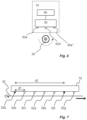
- the treatment unit 30 has a plurality of nozzles 32a-g arranged at different longitudinal positions along the thread 20 which passes by the treatment unit 30 during use.
- the direction of movement of the thread in use is indicated by the solid arrow in Fig. 5 .
- Each nozzle 32a-g is arranged to dispense a coating substance, such as ink, onto the thread 20 when the nozzle is activated.
- the system 10 further comprises a control unit 40 arranged to activate at least two of the nozzles 32a-g to dispense the coating substance such that the coating substance is absorbed by the thread 20 at different circumferential positions of the thread 20 when the thread 20 rotates about its longitudinal axis due to the thread engagement device 50, optionally arranged downstream the treatment unit 30.
- the relative position of two adjacently dispensed droplets of coating substance may be selected such that the droplets will at least to some extent overlap, i.e. a portion of the circumferential area of the thread 20 will be covered by two adjacent droplets.
- the rotation of the thread 20 is illustrated by the curved dashed arrow in Fig. 5 .
- the control unit 40 receives one or more input signals specifying the desired colour and/or colouring effect.
- the colour input preferably includes information regarding the exact colour, as well as the longitudinal start and stop positions of the thread 20 for that particular colour.
- the longitudinal start and stop position could be represented by specific times if the thread speed is determined.
- the colouring effect input preferably includes pattern information, e.g. if an even colouring is desired. Normally, a homogenous colouring would require coating on different circumferential positions in a close, or even the same, longitudinal range of the thread. On the other hand, a one-sided colouring effect would require coating on a single circumferential position only.
- the thread 20 has a certain rotation, or twist per length unit, it is possible to precisely dispense the coating substance at different circumferential positions of the thread 20 as the thread 20 passes by the treatment unit 30.
- the twist rate i.e. the rotational or twist angle per second. For example, if the twist per length unit is 360°/cm and the speed of the thread 20 is 2 cm/s, the resulting twist rate is 720°/s, i.e. two 360°revolutions per second.
- the twist rate may be used to calculate an activation timing required for each nozzle 32a-g such that each nozzle 32a-g can dispense the coating substance such that the coating substance will hit the thread 20 on a unique circumferential position of the thread 20.
- the twist of the thread 20 relates to a rotation of the thread 20 seen by an observer as the thread is moving in a longitudinal direction.
- the thread may also have a native twist, e.g. formed by the helical appearance of a multi-ply thread. When the helically arranged plies pass a fix longitudinal position it will appear as if the thread rotates with reference to the fix longitudinal position.
- the thread comprises only one ply or plies arranged in parallel along the longitudinal extension thereof, the twist or rotation is entirely produced by the thread engagement device 50.
- the important factor for achieving a desired treatment of the thread 20 is that the thread 20 rotates when it passes the treatment unit 30, so that the activation of the nozzles 32a-g of the treatment unit 30 can be controlled to dispense coating substance at unique circumferential positions of the thread 20 in use. This however also requires a specific distance between the nozzles 32a-g in order to achieve the desired treatment effect.
- the activation timing can also be based on the knowledge of the longitudinal distance d1 between each of the plurality of nozzles 32a-g. For example, it is possible to dispense a coating substance onto a thread 20 at the same longitudinal position and at two chosen circumferential positions, such as 0°and 180°, by knowing the longitudinal distance d1 between the respective nozzles 32a-g. For example, if the longitudinal distance between a first and a second nozzle 32a-g is 5 mm, giving the example above, it will take 0.25 seconds (5mm/ (2cm/s)) for a specific position of the thread 20 to move from the first nozzle 32a-g to the second nozzle 32a-g.
- the control unit 40 has processing capabilities and may comprise a processor with memory.
- the control unit 40 may receive input relating to a twist level parameter associated with the level of twist, e.g. twist angle per length unit of the thread 20 and a speed level parameter associated with the speed of the thread 20 passing through the treatment unit 30 in use.
- the input may be received via another device, e.g. a sensor, graphical user interface (not shown). Alternatively the input may be hard coded into the control unit 40.
- the control unit 40 may be further arranged to transmit a control signal to the treatment unit 30.
- the control signal sent by the control unit to the treatment unit 30 may be an activation signal for activating the nozzles 32a-g of the treatment unit 30 according to a dispensing timing scheme selected based on the received twist level parameter and speed level parameter.
- the control unit 40 may be arranged to process the twist level parameter and the speed level parameter and determining the dispensing timing scheme.
- the control signal sent to the treatment unit 30 may comprise information about the twist level parameter and the speed level parameter.
- the treatment unit 30 receives the control signal from the control unit 40 and dispenses a coating substance to the thread 20 via two or more of the nozzles 32a-g according to a dispensing timing scheme selected based on the received twist level parameter and speed level parameter.
- nozzles 32a-g are shown in Fig. 5
- the treatment unit 30 need only comprise at least two nozzles such as nozzles 32a and 32b.
- a typical inkjet head which is a suitable component for realizing the invention, comprises hundreds or even thousands of nozzles.
- Other dispensing technologies may also be used.
- Fig. 6 illustrates a variation of the system 10 in Fig. 5 .
- the nozzles 32a', 32a", 32a′′′ are arranged at different radial positions around the thread 20.
- the nozzles 32a', 32a", 32a′′′ may be arranged at a specific longitudinal position, or they may be distributed along the longitudinal direction. While Fig.
- Fig. 5 is a front view of the system 10
- Fig. 6 is a side view of the system 10 and the twist of the thread 20 that occurs as the thread 20 moves past the system 10 is shown by the semi-circular dashed arrow.
- the thread 20 is assumed to move in the direction of the arrow symbol provided in the centre of the thread 20.
- the system 10 in Fig. 6 also has a treatment unit 30 and a control unit 40 which operate in the same manner as described above in relation to Figs. 1 and 5 .
- the treatment unit 30 and the control unit 40 shown in Fig. 6 are configured to allow for simultaneous activation of the nozzles 32a', 32a", 32a′′′.
- a thread engagement device (not shown) may be suitable for the system 10 shown in Fig.
- the longitudinal distance between the nozzle sets can be made very small, as the circumferential distance between the nozzles 32a', 32a", 32a′′′ in each nozzle set will, in combination with the induced rotation, allow for an even colouring of the thread 20.
- the plurality of nozzles 32a-g may be arranged in a static nozzle array 70, e.g. further shown in Fig. 7 .
- the position of the nozzles 32a-g and other nozzles (not shown) are fixed on the treatment unit 30.
- the nozzles 32a-g are longitudinally separated by a fix distance d1. Recapturing the example above, if the intention is to dispense coating substance onto the thread 20 at the same longitudinal position thereof at 0°and at 180°it would be possible to calculate a required longitudinal distance d2 by the following formula: (180°)/(twist per length unit), wherein the twist per length unit is (360°/cm) from the example above.
- the required longitudinal distance d2 to achieve the required dispensing is 0.5cm.
- the fix distance d1 between two adjacent nozzles 32a-g may be very small such as below 0.05 mm.
- the control unit (not show in Fig. 7 , but connected to the treatment unit 30 in accordance with the description above) may be arranged to identify which nozzles 32a-g to activate, based on the calculated required longitudinal distance d2. For example, when the fix distance d1 is 1mm and the required longitudinal distance d2 is 0.5cm, i.e. 5mm, the first nozzle and the sixth nozzle may be identified for activation, since the sixth nozzle is located 5mm away from the first nozzle. Fig.
- the control unit 40 may activate the nozzles 32a-g to dispense a coating substance on a unique circumferential position of the thread 20.
- a required longitudinal distance d2 may still be calculated by the control unit 40 to identify a suitable nozzle pair, where a second nozzle of the nozzle pair is located at, or as close as possible to, the required longitudinal distance d2 measured from a first nozzle of the nozzle pair.
- the activation of any required nozzle 32a-g may be made using the activation signal and being based on the twist level parameter discussed above, and/or based on the desired result.
- the examples above illustrate the possibility of dispensing at two specific circumferential positions, optionally at the same longitudinal position of the thread 20 as long as the thread 20 rotates when passing the treatment unit 30. Instead, in some embodiments it is more preferred to dispense the coating substance at regular longitudinal intervals along the thread 20 but from different circumferential positions. However, for colours requiring a high saturation level it may be desired to dispense several droplets at the same longitudinal position.
- By being able to controllably dispensing the coating substance at different circumferential positions of the thread 20 it is possible to provide the thread 20 with novel coating features, such as homogeneous solid colour, solid colour with mixed shades, gradients, shades, simulated reflections, helical colouring pattern, one-side only colouring, etc.
- the length of the nozzle array may preferably be at least as long as the distance it takes for the thread 20 to rotate one 180° revolution around itself, and more preferably at least as long as the distance it takes for the thread 20 to rotate a 360° revolution around itself.
- the thread 20 may be advantageous to allow the thread 20 to rotate more than one revolution between the longitudinal ends of the nozzle array 70, i.e. between the first and last nozzle of the array 70. This could be particularly advantageous when more than two nozzles 32a-g are arranged in the treatment unit 30.
- By providing an induced rotation to make the thread 20 rotate several revolutions between the first nozzle 32a and the last nozzle 32g an even coating that evenly covers the outer surface of the thread 20 may be achieved by activating suitable nozzles arranged in between the first and the last nozzle.
- Other colouring effects may of course also be utilized.
- the control unit is configured to set the longitudinal distance d2 between the at least two activated nozzles 32a-g based on the twist per length unit ⁇ [rad/m] of the thread 20, in accordance with 20 ⁇ / ⁇ ⁇ d2 > 0. This means that the calculated required longitudinal distance d2 is set to allow the thread to twist up to 10 revolutions between the two associated nozzles.
- control unit 40 is further configured to set the longitudinal distance d2 between the nozzles to be activated based on the level of wetting of the thread. In alternative embodiments the control unit 40 is further configured to set the longitudinal distance d2 between the nozzles to be activated based on a pre-set colouring effect.
- the pre-set colouring effect may be selected from the group comprising homogeneous colouring pattern, one-side-only colouring pattern, random colouring pattern, or helical colouring pattern.
- the treatment unit 30 comprises nozzles 32a-g, which may be separated by a longitudinal distance d3 that may be increased or decreased.
- a first droplet is dispensed from a first nozzle 32a
- a subsequent droplet is dispensed from a second nozzle 32g.
- the longitudinal position of the secondly activated nozzle 32g may be adjusted, either by moving the secondly activated nozzle 32g relative the firstly activated nozzle 32a, or, as is shown in Fig. 8 , by moving the entire nozzle array 70 after the first nozzle 32a has been activated, but before the activation of the second nozzle 32g.
- the dispensed droplets could be diverted before they hit the thread 20 e.g. by applying an electromagnetic field.
- the control unit 40 is configured to set a longitudinal distance d4 between a first position at which a dispensed droplet from a first nozzle 32a is assumed to hit the thread 20 and a second position at which a subsequently dispensed droplet from a second nozzle 32e is assumed to hit the thread 20, and wherein the system 10 further comprises means 60 for changing the travel path of dispensed droplets in accordance with the longitudinal distance d4. This is shown in Fig. 9 . This makes it possible to arrange the nozzles 32a-g at different positions along the longitudinal extension or direction of the thread 20 depending on a desired dispensing scheme.
- a motor capable of adjusting the relative longitudinal distance d3 between the nozzles along and/or around the thread, or by changing the thread twist.
- the motor may receive input from the control unit 40.
- the relative position between the nozzles 23a-g may be adjusted according to the associated dispensing scheme. Hence, the higher the level of twist as indicated by the twist level parameter of the thread 20, the closer the at least two nozzles 32a-g may be positioned to each other i.e. the longitudinal distance d3 may be decreased.
- a lower level of twist as indicated by the twist level parameter is translated to a larger relative distance between the nozzles 32a-g i.e. the longitudinal distance d3 is increased.
- the longitudinal distance d3 between the at least two nozzles 32a-g it is possible to improve the coating quality of the thread 20, such that the coating substance is dispensed around the outer perimeter of the thread in a controlled manner.
- a motor may be connected to each additional nozzle such as to allow for adjustment of the longitudinal distance between each of the nozzles for example, the longitudinal distance between nozzle 32c and nozzle 32d.
- each nozzle dispenses a coating substance having a colour according to the CMYK colour model, where the primary colours are Cyan, Magenta, Yellow, and Black. It may thus be possible to dispense a wide variety of colours onto the thread by activating nozzles such that the total colouring substance will be a mix of the colouring substances dispensed by the nozzles.
- a nozzle head 80 is provided with multiple nozzle arrays 70a-d.
- Each nozzle array 70a-d may for example be an inkjet nozzle array, comprising thousands of nozzles.
- each nozzle array 70a-d may be associated with a single colour, illustrated according to the CMYK standard.
- each nozzle dispenses a coating substance having a colour comprising a mix of two or more primary colours of the CMYK colour model.
- each nozzle is arranged within a nozzle plate (not illustrated), e.g. a flat nozzle plate, extending in a longitudinal direction in relation to the thread.
- the method 200 being performed for providing treatment to at least one thread prior to being fed to a thread consuming unit, comprises a first step 202 of feeding the at least one thread in a downstream direction towards the thread consuming unit such that it engages with at least one thread engagement device whereby the at least one thread causes to rotate along its longitudinal axis. Feeding of the thread 20 may e.g. be performed by pulling the thread 20.
- the method 200 also comprises a step 204 of passing the at least one thread through a treatment unit having a plurality of nozzles arranged at different positions relative the at least one thread.
- the treatment unit is optionally arranged upstream the thread engagement device such that the rotation of the thread is occurring as the at least one thread is passing the treatment unit.
- Each nozzle is further configured to dispense one or more coating substances onto the at least one thread when activated, such that the thread may be treated (or coloured) in a customized manner due to the rotation of the thread.
Landscapes
- Engineering & Computer Science (AREA)
- Textile Engineering (AREA)
- Chemical & Material Sciences (AREA)
- Materials Engineering (AREA)
- Treatment Of Fiber Materials (AREA)
- Application Of Or Painting With Fluid Materials (AREA)
- Yarns And Mechanical Finishing Of Yarns Or Ropes (AREA)
- Investigating Materials By The Use Of Optical Means Adapted For Particular Applications (AREA)
Claims (10)
- System (10) zur Inline-Behandlung von zumindest einem Faden (20) zur Verwendung mit einer fadenverbrauchenden Vorrichtung (100), die eine Stickeinheit, eine Näheinheit, eine Strickeinheit oder eine Webeeinheit ist, aufweisendeine Behandlungseinheit (30) mit einer Vielzahl von Düsen (32a-g), die an verschiedenen Längspositionen relativ zu dem zumindest einen Faden (20) angeordnet sind, wobei der zumindest eine Faden (20) im Gebrauch in Bewegung ist und jede Düse derart ausgebildet ist, dass sie eine oder mehrere Beschichtungssubstanzen auf den zumindest einen Faden (20) abgibt, wenn sie aktiviert wird; undmindestens eine Faden-Eingriffsvorrichtung (50), wobei die mindestens eine Faden-Eingriffsvorrichtung (50) ein statisches Führungselement (52) ist, das eine Eingriffsfläche (51) aufweist, wobei die mindestens eine Faden-Eingriffsvorrichtung (50) derart ausgebildet ist, um:
ein Drehmoment auf den mindestens einen Faden (20) auszuüben, um eine Drehung des mindestens einen Fadens (20) einzuleiten, und wobei die Eingriffsfläche (51), die, wenn sie in Kontakt mit dem mindestens einen Faden (20) steht, eine Drehung des mindestens einen Fadens (20) entlang seiner Längsachse bewirkt, während sich der mindestens eine Faden (20) durch die Behandlungseinheit (30) bewegt. - System (10) nach Anspruch 1, wobei eine der mindestens einen Faden-Eingriffsvorrichtungen (50) an einer stromabwärtigen Seite der Behandlungseinheit (30) entlang der Bewegungsrichtung des mindestens einen Fadens (20) angeordnet ist.
- System (10) nach einem der Ansprüche 1 bis 2, wobei die mindestens eine Faden-Eingriffsvorrichtung (50) ein oder mehrere rohrförmige Elemente (54) ist, durch die der mindestens eine Faden (20) geführt wird.
- System (10) nach Anspruch 3, wobei ein rohrförmiges Element (54) auf einer stromabwärtigen Seite der Behandlungseinheit (30) angeordnet ist, und/oder ein rohrförmiges Element (54) auf einer stromaufwärtigen Seite der Behandlungseinheit (30) angeordnet ist
- System (10) nach Anspruch 3 oder 4, wobei der Innendurchmesser des rohrförmigen Elements (54) so gewählt ist, dass die Innenwände des rohrförmigen Elements (54) eine Reibungskraft auf den mindestens einen Faden (20) ausüben.
- System (10) nach einem der Ansprüche 4 bis 5, wobei das rohrförmige Element (54) entlang seiner Längsachse drehbar ist.
- System (10) nach einem der Ansprüche 4 bis 5, wobei die mindestens eine Faden-Eingriffsvorrichtung (50) ein rotierendes Eingriffselement (56) mit einer äußeren Fläche (56a) aufweist, auf der der mindestens eine Faden (20) geführt wird, um eine Drehung zu bewirken.
- Fadenverbrauchende Vorrichtung (100), aufweisend eine fadenverbrauchende Einheit (90), die eine Stickeinheit, eine Näheinheit, eine Strickeinheit oder eine Webeeinheit ist, und ein System (10) nach einem der vorstehenden Ansprüche.
- Verfahren zum Bereitstellen eines Systems zur Inline-Behandlung eines Fadens, aufweisend:Bereitstellen einer Behandlungseinheit mit einer Vielzahl von Düsen, die an verschiedenen Längspositionen entlang des Fadens angeordnet sind, wobei jede Düse derart ausgebildet ist, dass sie eine Beschichtungssubstanz auf den Faden abgibt, wenn sie aktiviert wird; undBereitstellen einer Faden-Eingriffsvorrichtung, wobei die Faden-Eingriffsvorrichtung ein statisches Führungselement (52) ist, das zur Ausbildung eines Drehmoments auf den mindestens einen Faden (20) ausgebildet ist, um eine Drehung des mindestens einen Fadens (20) einzuleiten, und wobei die Faden-Eingriffsvorrichtung (50) eine Eingriffsfläche (51) aufweist, die, wenn sie in Kontakt mit dem mindestens einen Faden (20) steht, eine Drehung des mindestens einen Fadens entlang seiner Längsachse bewirkt, während sich der Faden durch die Behandlungseinheit bewegt.
- Verfahren zum Bereitstellen einer Behandlung für zumindest einen Faden, bevor dieser einer fadenverbrauchenden Vorrichtung zugeführt wird, die eine Stickeinheit, eine Näheinheit, eine Strickeinheit oder eine Webeeinheit ist, wobei das Verfahren aufweist:Zuführen des mindestens einen Fadens, so dass er mit mindestens einer Faden-Eingriffsvorrichtung zusammenwirkt, wobei die Faden-Eingriffsvorrichtung ein statisches Führungselement ist,Anwenden eines Drehmoments auf den mindestens einen Faden, um eine Drehung des mindestens einen Fadens einzuleiten, so dass dann, wenn eine Eingriffsfläche der Faden-Eingriffsvorrichtung in Kontakt mit dem mindestens einen Faden steht, sie eine Drehung des mindestens einen Fadens entlang seiner Längsachse bewirkt,Führen des mindestens einen Fadens durch eine Behandlungseinheit mit einer Vielzahl von Düsen, die an verschiedenen Positionen relativ zu dem mindestens einen Faden angeordnet sind, wobei jede Düse derart ausgebildet ist, dass sie bei Aktivierung eine oder mehrere Beschichtungssubstanzen auf den mindestens einen Faden abgibt.
Applications Claiming Priority (2)
| Application Number | Priority Date | Filing Date | Title |
|---|---|---|---|
| SE1650668A SE539759C2 (en) | 2016-05-17 | 2016-05-17 | A system for in-line treatment of thread |
| PCT/SE2017/050516 WO2017200473A1 (en) | 2016-05-17 | 2017-05-17 | A system for in-line treatment of thread |
Publications (4)
| Publication Number | Publication Date |
|---|---|
| EP3458635A1 EP3458635A1 (de) | 2019-03-27 |
| EP3458635A4 EP3458635A4 (de) | 2020-02-19 |
| EP3458635C0 EP3458635C0 (de) | 2023-07-26 |
| EP3458635B1 true EP3458635B1 (de) | 2023-07-26 |
Family
ID=60326971
Family Applications (1)
| Application Number | Title | Priority Date | Filing Date |
|---|---|---|---|
| EP17799776.4A Active EP3458635B1 (de) | 2016-05-17 | 2017-05-17 | System zur inline-behandlung von faden |
Country Status (18)
| Country | Link |
|---|---|
| US (2) | US11352722B2 (de) |
| EP (1) | EP3458635B1 (de) |
| JP (1) | JP7239326B2 (de) |
| KR (1) | KR102340711B1 (de) |
| CN (2) | CN109312513A (de) |
| AU (1) | AU2017265254B2 (de) |
| BR (1) | BR112018073512B1 (de) |
| CA (1) | CA3023682A1 (de) |
| CL (1) | CL2018003254A1 (de) |
| EA (1) | EA201892559A1 (de) |
| IL (1) | IL263029B (de) |
| MX (1) | MX2018013920A (de) |
| PH (1) | PH12018502368A1 (de) |
| PL (1) | PL3458635T3 (de) |
| SE (1) | SE539759C2 (de) |
| UA (1) | UA126967C2 (de) |
| WO (1) | WO2017200473A1 (de) |
| ZA (1) | ZA201808324B (de) |
Families Citing this family (14)
| Publication number | Priority date | Publication date | Assignee | Title |
|---|---|---|---|---|
| SE1651157A1 (en) | 2016-08-28 | 2018-02-20 | Inventech Europe Ab | A treatment unit for in-line treatment of threads |
| SE543382C2 (en) | 2018-09-15 | 2020-12-29 | Coloreel Group AB | A method and a treatment unit for in-line treatment of thread |
| US10525734B1 (en) | 2018-11-01 | 2020-01-07 | Xerox Corporation | System for thread printing using image-based feedback |
| US11186929B2 (en) | 2018-11-01 | 2021-11-30 | Xerox Corporation | Inkjet loom weaving machine |
| EP3674464B1 (de) | 2018-12-28 | 2023-05-24 | Ricoh Company, Ltd. | Flüssigkeitsausstossvorrichtung und flüssigkeitsausstosseinrichtung und färbevorrichtung damit |
| US11247488B2 (en) | 2019-03-08 | 2022-02-15 | Palo Alto Research Center Incorporated | Printer head for strand element printing |
| CN110042555A (zh) * | 2019-04-17 | 2019-07-23 | 江南大学 | 一种扁丝经编生产用自动喷涂装置及经编机 |
| WO2020229940A1 (en) | 2019-05-10 | 2020-11-19 | Invista Textiles (U.K.) Limited | Yarn drying and color fixation |
| EP3760778B1 (de) * | 2019-07-04 | 2024-06-19 | SUPERBA (Société par Actions Simplifiée) | Vorrichtung zum färben eines fadens |
| US11318757B2 (en) | 2019-07-09 | 2022-05-03 | Xerox Corporation | Method and apparatus for digital dyeing of thread |
| CN110747573B (zh) * | 2019-11-13 | 2020-10-09 | 安徽正美线业科技有限责任公司 | 一种纺织机用纱线导向装置及其工作方法 |
| US11897188B2 (en) | 2020-01-30 | 2024-02-13 | Xerox Corporation | Method and system for 3D printing on fabric |
| CN112609311B (zh) * | 2020-12-08 | 2022-11-04 | 义乌市大和针织有限公司 | 一种超高分子聚乙烯纤维袜子的生产系统及其除静电方法 |
| US11599312B1 (en) | 2021-09-21 | 2023-03-07 | Xerox Corporation | System and method for secure delivery of printed documents via mobile print center |
Family Cites Families (31)
| Publication number | Priority date | Publication date | Assignee | Title |
|---|---|---|---|---|
| ES425475A1 (es) * | 1973-04-18 | 1976-06-16 | Rhone Poulenc Textile | Perfeccionamientos en dispositivos para la inyeccion modu- lable de por lo menos un fluido en por lo menos un hilo en progresion dentro de un espacio restringido. |
| KR800000691B1 (ko) | 1976-06-24 | 1980-07-21 | 오다 기요다카 | 권축 필라멘트사를 제조하기 위한 가연 장치 |
| JPS5865084A (ja) | 1981-10-13 | 1983-04-18 | 蛇の目ミシン工業株式会社 | ミシン糸の簡易迅速染色法 |
| JPH06305129A (ja) | 1993-04-23 | 1994-11-01 | Canon Inc | インクジェットプリント装置及び方法及びそれを備えた刺繍装置 |
| US6189989B1 (en) * | 1993-04-12 | 2001-02-20 | Canon Kabushiki Kaisha | Embroidering using ink jet printing apparatus |
| JPH0742085A (ja) | 1993-07-29 | 1995-02-10 | Seiren Co Ltd | 糸のインクジェット染色法 |
| JPH0770952A (ja) | 1993-08-20 | 1995-03-14 | Seiren Co Ltd | 糸のインクジェット染色法 |
| DE4434566C2 (de) | 1994-09-28 | 2002-07-18 | Rieter Ingolstadt Spinnerei | Paraffiniereinrichtung |
| EP0784108A1 (de) * | 1996-01-13 | 1997-07-16 | Akzo Nobel N.V. | Schlichtemittelfreies getangeltes Multifilamentgarn und Verfahren zu dessen Herstellung |
| US5745628A (en) | 1997-01-13 | 1998-04-28 | Alcatel Na Cable Systems, Inc. | Method and apparatus for identifying a region of an S-Z stranded cable core and for marking an outer sheath covering the S-Z stranded cable core to indicate a region thereunder |
| JPH11207963A (ja) | 1998-01-29 | 1999-08-03 | Hitachi Ltd | 静電インクジェット記録装置 |
| GB2324541B (en) * | 1998-08-28 | 1999-06-16 | Cadcam Tech Ltd | The dynamic dyeing and colour control of yarns |
| BE1013539A6 (nl) | 2000-05-25 | 2002-03-05 | Picanol Nv | Werkwijze en inrichting voor het aanbrengen van materie op een draad bij een textielmachine. |
| IT1316139B1 (it) * | 2000-09-15 | 2003-03-28 | Durst Phototechnik Ag | Dispositivo di stampa a getto di inchiostro. |
| JP2002200381A (ja) | 2000-12-28 | 2002-07-16 | Brother Ind Ltd | 糸着色ミシン及びその制御方法 |
| ITMC20010012A1 (it) | 2001-02-08 | 2001-05-09 | Linea Tessile Srl | Procedimento di tintura di filato a mezzo sistema a getto d'inchiostro. |
| CN2490176Y (zh) * | 2001-03-22 | 2002-05-08 | 卢峰 | 纱线均匀涂敷装置 |
| US6926772B2 (en) | 2002-02-27 | 2005-08-09 | 3M Innovative Properties Company | Strand coating device and method |
| JP2003342867A (ja) | 2002-05-24 | 2003-12-03 | Hideo Kuwabara | 糸の先染め方法及び染め装置 |
| JP4477840B2 (ja) | 2002-08-09 | 2010-06-09 | 矢崎総業株式会社 | 物品の自動マーキング方法及び自動マーキング装置 |
| EP1484439A1 (de) | 2003-06-06 | 2004-12-08 | Picanol N.V. | Verfahren und Vorrichtung zum Auftragen von mehreren Substanzen auf ein Garn |
| US7308561B2 (en) | 2003-12-12 | 2007-12-11 | Alcatel Lucent | Fast, scalable pattern-matching engine |
| JP2006299462A (ja) | 2005-04-21 | 2006-11-02 | Gifu Prefecture | 色柄横編機 |
| JP4977362B2 (ja) * | 2005-12-09 | 2012-07-18 | 矢崎総業株式会社 | ローラ |
| FR2907798A1 (fr) * | 2006-10-30 | 2008-05-02 | Superba Sas | Procede de traitement de fils par tricotage-detricotage |
| FR2907799B1 (fr) * | 2006-10-30 | 2009-01-23 | Superba Sas | Procede de traitement de fils par tricotage-detricotage |
| CN201439265U (zh) | 2009-08-25 | 2010-04-21 | 深圳九星印刷包装集团有限公司 | 在线喷码装置 |
| KR100985471B1 (ko) * | 2009-11-03 | 2010-10-05 | 주식회사 스페이스솔루션 | 실시간 염색 기능을 구비한 자수기 |
| WO2011073730A1 (en) * | 2009-12-17 | 2011-06-23 | Officine Maccaferri S.P.A. | Plastic open mesh net manufacturing device and machine |
| US20140349034A1 (en) * | 2011-09-14 | 2014-11-27 | Inventech Europe Ab | Coating Device for Coating an Elongated Substrate |
| SE539534C2 (en) | 2016-03-07 | 2017-10-10 | Inventech Europe Ab | A system and method for in-line treatment of thread for use with a thread consumption device |
-
2016
- 2016-05-17 SE SE1650668A patent/SE539759C2/en unknown
-
2017
- 2017-05-17 KR KR1020187036567A patent/KR102340711B1/ko active Active
- 2017-05-17 WO PCT/SE2017/050516 patent/WO2017200473A1/en not_active Ceased
- 2017-05-17 EA EA201892559A patent/EA201892559A1/ru unknown
- 2017-05-17 JP JP2018560650A patent/JP7239326B2/ja active Active
- 2017-05-17 EP EP17799776.4A patent/EP3458635B1/de active Active
- 2017-05-17 CN CN201780031059.9A patent/CN109312513A/zh active Pending
- 2017-05-17 UA UAA201812230A patent/UA126967C2/uk unknown
- 2017-05-17 US US16/302,358 patent/US11352722B2/en active Active
- 2017-05-17 CN CN202211412761.9A patent/CN115710784A/zh active Pending
- 2017-05-17 CA CA3023682A patent/CA3023682A1/en active Pending
- 2017-05-17 BR BR112018073512-4A patent/BR112018073512B1/pt active IP Right Grant
- 2017-05-17 AU AU2017265254A patent/AU2017265254B2/en active Active
- 2017-05-17 PL PL17799776.4T patent/PL3458635T3/pl unknown
- 2017-05-17 MX MX2018013920A patent/MX2018013920A/es unknown
-
2018
- 2018-11-09 PH PH12018502368A patent/PH12018502368A1/en unknown
- 2018-11-15 IL IL263029A patent/IL263029B/en unknown
- 2018-11-16 CL CL2018003254A patent/CL2018003254A1/es unknown
- 2018-12-10 ZA ZA2018/08324A patent/ZA201808324B/en unknown
-
2022
- 2022-06-02 US US17/831,005 patent/US20220290343A1/en not_active Abandoned
Also Published As
| Publication number | Publication date |
|---|---|
| JP2019520488A (ja) | 2019-07-18 |
| WO2017200473A1 (en) | 2017-11-23 |
| EP3458635C0 (de) | 2023-07-26 |
| US20220290343A1 (en) | 2022-09-15 |
| CA3023682A1 (en) | 2017-11-23 |
| CN109312513A (zh) | 2019-02-05 |
| AU2017265254B2 (en) | 2022-02-03 |
| UA126967C2 (uk) | 2023-03-01 |
| KR20190007051A (ko) | 2019-01-21 |
| IL263029B (en) | 2022-06-01 |
| US11352722B2 (en) | 2022-06-07 |
| BR112018073512A2 (pt) | 2019-03-26 |
| PL3458635T3 (pl) | 2023-12-27 |
| EP3458635A1 (de) | 2019-03-27 |
| KR102340711B1 (ko) | 2021-12-21 |
| IL263029A (en) | 2018-12-31 |
| CN115710784A (zh) | 2023-02-24 |
| JP7239326B2 (ja) | 2023-03-14 |
| PH12018502368A1 (en) | 2019-09-09 |
| EA201892559A1 (ru) | 2019-06-28 |
| AU2017265254A1 (en) | 2018-12-20 |
| BR112018073512B1 (pt) | 2022-09-20 |
| SE539759C2 (en) | 2017-11-21 |
| US20190276956A1 (en) | 2019-09-12 |
| CL2018003254A1 (es) | 2019-02-01 |
| SE1650668A1 (en) | 2017-11-18 |
| EP3458635A4 (de) | 2020-02-19 |
| ZA201808324B (en) | 2019-08-28 |
| MX2018013920A (es) | 2019-08-12 |
Similar Documents
| Publication | Publication Date | Title |
|---|---|---|
| EP3458635B1 (de) | System zur inline-behandlung von faden | |
| EP3426834B1 (de) | System und verfahren zur inline-behandlung von garn zur verwendung mit einer garnverbrauchsvorrichtung | |
| AU2019341015A1 (en) | A method for in-line treatment of a thread and a system therefore comprising a treatment unit and a thread speed sensor | |
| EP3850134B1 (de) | System und verfahren zur inline-behandlung zweier oder mehrerer fäden zur verwendung mit einer fadenverbrauchenden vorrichtung | |
| HK1262109A1 (en) | A system for in-line treatment of thread | |
| EA045170B1 (ru) | Система поточной обработки нити | |
| HK1260818A1 (en) | A system and method for in-line treatment of thread for use with a thread consumption device | |
| HK1260818B (zh) | 一种与线消耗设备一起使用的用於在线处理线的系统和方法 |
Legal Events
| Date | Code | Title | Description |
|---|---|---|---|
| STAA | Information on the status of an ep patent application or granted ep patent |
Free format text: STATUS: THE INTERNATIONAL PUBLICATION HAS BEEN MADE |
|
| PUAI | Public reference made under article 153(3) epc to a published international application that has entered the european phase |
Free format text: ORIGINAL CODE: 0009012 |
|
| STAA | Information on the status of an ep patent application or granted ep patent |
Free format text: STATUS: REQUEST FOR EXAMINATION WAS MADE |
|
| 17P | Request for examination filed |
Effective date: 20181210 |
|
| AK | Designated contracting states |
Kind code of ref document: A1 Designated state(s): AL AT BE BG CH CY CZ DE DK EE ES FI FR GB GR HR HU IE IS IT LI LT LU LV MC MK MT NL NO PL PT RO RS SE SI SK SM TR |
|
| AX | Request for extension of the european patent |
Extension state: BA ME |
|
| RIN1 | Information on inventor provided before grant (corrected) |
Inventor name: STABERG, JOAKIM Inventor name: EKLIND, MARTIN |
|
| DAV | Request for validation of the european patent (deleted) | ||
| DAX | Request for extension of the european patent (deleted) | ||
| A4 | Supplementary search report drawn up and despatched |
Effective date: 20200116 |
|
| RIC1 | Information provided on ipc code assigned before grant |
Ipc: D06P 5/30 20060101ALI20200110BHEP Ipc: D04B 35/22 20060101ALI20200110BHEP Ipc: D05C 11/24 20060101AFI20200110BHEP Ipc: D05B 67/00 20060101ALI20200110BHEP Ipc: D03J 1/04 20060101ALI20200110BHEP |
|
| STAA | Information on the status of an ep patent application or granted ep patent |
Free format text: STATUS: EXAMINATION IS IN PROGRESS |
|
| 17Q | First examination report despatched |
Effective date: 20210114 |
|
| GRAP | Despatch of communication of intention to grant a patent |
Free format text: ORIGINAL CODE: EPIDOSNIGR1 |
|
| STAA | Information on the status of an ep patent application or granted ep patent |
Free format text: STATUS: GRANT OF PATENT IS INTENDED |
|
| INTG | Intention to grant announced |
Effective date: 20230214 |
|
| GRAS | Grant fee paid |
Free format text: ORIGINAL CODE: EPIDOSNIGR3 |
|
| GRAA | (expected) grant |
Free format text: ORIGINAL CODE: 0009210 |
|
| STAA | Information on the status of an ep patent application or granted ep patent |
Free format text: STATUS: THE PATENT HAS BEEN GRANTED |
|
| AK | Designated contracting states |
Kind code of ref document: B1 Designated state(s): AL AT BE BG CH CY CZ DE DK EE ES FI FR GB GR HR HU IE IS IT LI LT LU LV MC MK MT NL NO PL PT RO RS SE SI SK SM TR |
|
| REG | Reference to a national code |
Ref country code: CH Ref legal event code: EP |
|
| REG | Reference to a national code |
Ref country code: IE Ref legal event code: FG4D |
|
| REG | Reference to a national code |
Ref country code: DE Ref legal event code: R096 Ref document number: 602017071852 Country of ref document: DE |
|
| U01 | Request for unitary effect filed |
Effective date: 20230824 |
|
| U07 | Unitary effect registered |
Designated state(s): AT BE BG DE DK EE FI FR IT LT LU LV MT NL PT SE SI Effective date: 20230831 |
|
| REG | Reference to a national code |
Ref country code: LT Ref legal event code: MG9D |
|
| PG25 | Lapsed in a contracting state [announced via postgrant information from national office to epo] |
Ref country code: GR Free format text: LAPSE BECAUSE OF FAILURE TO SUBMIT A TRANSLATION OF THE DESCRIPTION OR TO PAY THE FEE WITHIN THE PRESCRIBED TIME-LIMIT Effective date: 20231027 |
|
| PG25 | Lapsed in a contracting state [announced via postgrant information from national office to epo] |
Ref country code: IS Free format text: LAPSE BECAUSE OF FAILURE TO SUBMIT A TRANSLATION OF THE DESCRIPTION OR TO PAY THE FEE WITHIN THE PRESCRIBED TIME-LIMIT Effective date: 20231126 |
|
| PG25 | Lapsed in a contracting state [announced via postgrant information from national office to epo] |
Ref country code: RS Free format text: LAPSE BECAUSE OF FAILURE TO SUBMIT A TRANSLATION OF THE DESCRIPTION OR TO PAY THE FEE WITHIN THE PRESCRIBED TIME-LIMIT Effective date: 20230726 Ref country code: NO Free format text: LAPSE BECAUSE OF FAILURE TO SUBMIT A TRANSLATION OF THE DESCRIPTION OR TO PAY THE FEE WITHIN THE PRESCRIBED TIME-LIMIT Effective date: 20231026 Ref country code: IS Free format text: LAPSE BECAUSE OF FAILURE TO SUBMIT A TRANSLATION OF THE DESCRIPTION OR TO PAY THE FEE WITHIN THE PRESCRIBED TIME-LIMIT Effective date: 20231126 Ref country code: HR Free format text: LAPSE BECAUSE OF FAILURE TO SUBMIT A TRANSLATION OF THE DESCRIPTION OR TO PAY THE FEE WITHIN THE PRESCRIBED TIME-LIMIT Effective date: 20230726 Ref country code: GR Free format text: LAPSE BECAUSE OF FAILURE TO SUBMIT A TRANSLATION OF THE DESCRIPTION OR TO PAY THE FEE WITHIN THE PRESCRIBED TIME-LIMIT Effective date: 20231027 |
|
| PG25 | Lapsed in a contracting state [announced via postgrant information from national office to epo] |
Ref country code: ES Free format text: LAPSE BECAUSE OF FAILURE TO SUBMIT A TRANSLATION OF THE DESCRIPTION OR TO PAY THE FEE WITHIN THE PRESCRIBED TIME-LIMIT Effective date: 20230726 |
|
| REG | Reference to a national code |
Ref country code: DE Ref legal event code: R097 Ref document number: 602017071852 Country of ref document: DE |
|
| PG25 | Lapsed in a contracting state [announced via postgrant information from national office to epo] |
Ref country code: SM Free format text: LAPSE BECAUSE OF FAILURE TO SUBMIT A TRANSLATION OF THE DESCRIPTION OR TO PAY THE FEE WITHIN THE PRESCRIBED TIME-LIMIT Effective date: 20230726 Ref country code: RO Free format text: LAPSE BECAUSE OF FAILURE TO SUBMIT A TRANSLATION OF THE DESCRIPTION OR TO PAY THE FEE WITHIN THE PRESCRIBED TIME-LIMIT Effective date: 20230726 Ref country code: ES Free format text: LAPSE BECAUSE OF FAILURE TO SUBMIT A TRANSLATION OF THE DESCRIPTION OR TO PAY THE FEE WITHIN THE PRESCRIBED TIME-LIMIT Effective date: 20230726 Ref country code: CZ Free format text: LAPSE BECAUSE OF FAILURE TO SUBMIT A TRANSLATION OF THE DESCRIPTION OR TO PAY THE FEE WITHIN THE PRESCRIBED TIME-LIMIT Effective date: 20230726 Ref country code: SK Free format text: LAPSE BECAUSE OF FAILURE TO SUBMIT A TRANSLATION OF THE DESCRIPTION OR TO PAY THE FEE WITHIN THE PRESCRIBED TIME-LIMIT Effective date: 20230726 |
|
| PLBE | No opposition filed within time limit |
Free format text: ORIGINAL CODE: 0009261 |
|
| STAA | Information on the status of an ep patent application or granted ep patent |
Free format text: STATUS: NO OPPOSITION FILED WITHIN TIME LIMIT |
|
| 26N | No opposition filed |
Effective date: 20240429 |
|
| U21 | Renewal fee for the european patent with unitary effect paid with additional fee |
Year of fee payment: 8 Effective date: 20241113 |
|
| PG25 | Lapsed in a contracting state [announced via postgrant information from national office to epo] |
Ref country code: MC Free format text: LAPSE BECAUSE OF FAILURE TO SUBMIT A TRANSLATION OF THE DESCRIPTION OR TO PAY THE FEE WITHIN THE PRESCRIBED TIME-LIMIT Effective date: 20230726 |
|
| PG25 | Lapsed in a contracting state [announced via postgrant information from national office to epo] |
Ref country code: MC Free format text: LAPSE BECAUSE OF FAILURE TO SUBMIT A TRANSLATION OF THE DESCRIPTION OR TO PAY THE FEE WITHIN THE PRESCRIBED TIME-LIMIT Effective date: 20230726 |
|
| PG25 | Lapsed in a contracting state [announced via postgrant information from national office to epo] |
Ref country code: IE Free format text: LAPSE BECAUSE OF NON-PAYMENT OF DUE FEES Effective date: 20240517 |
|
| U20 | Renewal fee for the european patent with unitary effect paid |
Year of fee payment: 9 Effective date: 20250513 |
|
| PGFP | Annual fee paid to national office [announced via postgrant information from national office to epo] |
Ref country code: PL Payment date: 20250415 Year of fee payment: 9 |
|
| PGFP | Annual fee paid to national office [announced via postgrant information from national office to epo] |
Ref country code: GB Payment date: 20250512 Year of fee payment: 9 |
|
| PGFP | Annual fee paid to national office [announced via postgrant information from national office to epo] |
Ref country code: CH Payment date: 20250601 Year of fee payment: 9 |
|
| PGFP | Annual fee paid to national office [announced via postgrant information from national office to epo] |
Ref country code: TR Payment date: 20250415 Year of fee payment: 9 |
|
| PG25 | Lapsed in a contracting state [announced via postgrant information from national office to epo] |
Ref country code: CY Free format text: LAPSE BECAUSE OF FAILURE TO SUBMIT A TRANSLATION OF THE DESCRIPTION OR TO PAY THE FEE WITHIN THE PRESCRIBED TIME-LIMIT; INVALID AB INITIO Effective date: 20170517 |
|
| PG25 | Lapsed in a contracting state [announced via postgrant information from national office to epo] |
Ref country code: HU Free format text: LAPSE BECAUSE OF FAILURE TO SUBMIT A TRANSLATION OF THE DESCRIPTION OR TO PAY THE FEE WITHIN THE PRESCRIBED TIME-LIMIT; INVALID AB INITIO Effective date: 20170517 |
|
| REG | Reference to a national code |
Ref country code: CH Ref legal event code: R14 Free format text: ST27 STATUS EVENT CODE: U-0-0-R10-R14 (AS PROVIDED BY THE NATIONAL OFFICE) Effective date: 20251127 Ref country code: CH Ref legal event code: R17 Free format text: ST27 STATUS EVENT CODE: U-0-0-R10-R17 (AS PROVIDED BY THE NATIONAL OFFICE) Effective date: 20251127 |
|
| REG | Reference to a national code |
Ref country code: GB Ref legal event code: 732E Free format text: REGISTERED BETWEEN 20251204 AND 20251210 |