EP3457484B1 - Lithiierung während des betriebs nach soh-überwachung - Google Patents
Lithiierung während des betriebs nach soh-überwachung Download PDFInfo
- Publication number
- EP3457484B1 EP3457484B1 EP18194939.7A EP18194939A EP3457484B1 EP 3457484 B1 EP3457484 B1 EP 3457484B1 EP 18194939 A EP18194939 A EP 18194939A EP 3457484 B1 EP3457484 B1 EP 3457484B1
- Authority
- EP
- European Patent Office
- Prior art keywords
- lithium
- anodes
- cathodes
- battery
- electrodes
- Prior art date
- Legal status (The legal status is an assumption and is not a legal conclusion. Google has not performed a legal analysis and makes no representation as to the accuracy of the status listed.)
- Active
Links
Images






Classifications
-
- H—ELECTRICITY
- H01—ELECTRIC ELEMENTS
- H01M—PROCESSES OR MEANS, e.g. BATTERIES, FOR THE DIRECT CONVERSION OF CHEMICAL ENERGY INTO ELECTRICAL ENERGY
- H01M10/00—Secondary cells; Manufacture thereof
- H01M10/42—Methods or arrangements for servicing or maintenance of secondary cells or secondary half-cells
- H01M10/4242—Regeneration of electrolyte or reactants
-
- H—ELECTRICITY
- H01—ELECTRIC ELEMENTS
- H01M—PROCESSES OR MEANS, e.g. BATTERIES, FOR THE DIRECT CONVERSION OF CHEMICAL ENERGY INTO ELECTRICAL ENERGY
- H01M10/00—Secondary cells; Manufacture thereof
- H01M10/42—Methods or arrangements for servicing or maintenance of secondary cells or secondary half-cells
- H01M10/425—Structural combination with electronic components, e.g. electronic circuits integrated to the outside of the casing
-
- G—PHYSICS
- G01—MEASURING; TESTING
- G01R—MEASURING ELECTRIC VARIABLES; MEASURING MAGNETIC VARIABLES
- G01R31/00—Arrangements for testing electric properties; Arrangements for locating electric faults; Arrangements for electrical testing characterised by what is being tested not provided for elsewhere
- G01R31/36—Arrangements for testing, measuring or monitoring the electrical condition of accumulators or electric batteries, e.g. capacity or state of charge [SoC]
- G01R31/382—Arrangements for monitoring battery or accumulator variables, e.g. SoC
-
- G—PHYSICS
- G01—MEASURING; TESTING
- G01R—MEASURING ELECTRIC VARIABLES; MEASURING MAGNETIC VARIABLES
- G01R31/00—Arrangements for testing electric properties; Arrangements for locating electric faults; Arrangements for electrical testing characterised by what is being tested not provided for elsewhere
- G01R31/36—Arrangements for testing, measuring or monitoring the electrical condition of accumulators or electric batteries, e.g. capacity or state of charge [SoC]
- G01R31/392—Determining battery ageing or deterioration, e.g. state of health
-
- H—ELECTRICITY
- H01—ELECTRIC ELEMENTS
- H01M—PROCESSES OR MEANS, e.g. BATTERIES, FOR THE DIRECT CONVERSION OF CHEMICAL ENERGY INTO ELECTRICAL ENERGY
- H01M10/00—Secondary cells; Manufacture thereof
- H01M10/05—Accumulators with non-aqueous electrolyte
- H01M10/052—Li-accumulators
-
- H—ELECTRICITY
- H01—ELECTRIC ELEMENTS
- H01M—PROCESSES OR MEANS, e.g. BATTERIES, FOR THE DIRECT CONVERSION OF CHEMICAL ENERGY INTO ELECTRICAL ENERGY
- H01M10/00—Secondary cells; Manufacture thereof
- H01M10/05—Accumulators with non-aqueous electrolyte
- H01M10/052—Li-accumulators
- H01M10/0525—Rocking-chair batteries, i.e. batteries with lithium insertion or intercalation in both electrodes; Lithium-ion batteries
-
- H—ELECTRICITY
- H01—ELECTRIC ELEMENTS
- H01M—PROCESSES OR MEANS, e.g. BATTERIES, FOR THE DIRECT CONVERSION OF CHEMICAL ENERGY INTO ELECTRICAL ENERGY
- H01M10/00—Secondary cells; Manufacture thereof
- H01M10/05—Accumulators with non-aqueous electrolyte
- H01M10/058—Construction or manufacture
-
- H—ELECTRICITY
- H01—ELECTRIC ELEMENTS
- H01M—PROCESSES OR MEANS, e.g. BATTERIES, FOR THE DIRECT CONVERSION OF CHEMICAL ENERGY INTO ELECTRICAL ENERGY
- H01M10/00—Secondary cells; Manufacture thereof
- H01M10/42—Methods or arrangements for servicing or maintenance of secondary cells or secondary half-cells
- H01M10/44—Methods for charging or discharging
-
- H—ELECTRICITY
- H01—ELECTRIC ELEMENTS
- H01M—PROCESSES OR MEANS, e.g. BATTERIES, FOR THE DIRECT CONVERSION OF CHEMICAL ENERGY INTO ELECTRICAL ENERGY
- H01M10/00—Secondary cells; Manufacture thereof
- H01M10/42—Methods or arrangements for servicing or maintenance of secondary cells or secondary half-cells
- H01M10/48—Accumulators combined with arrangements for measuring, testing or indicating the condition of cells, e.g. the level or density of the electrolyte
-
- H—ELECTRICITY
- H01—ELECTRIC ELEMENTS
- H01M—PROCESSES OR MEANS, e.g. BATTERIES, FOR THE DIRECT CONVERSION OF CHEMICAL ENERGY INTO ELECTRICAL ENERGY
- H01M10/00—Secondary cells; Manufacture thereof
- H01M10/42—Methods or arrangements for servicing or maintenance of secondary cells or secondary half-cells
- H01M10/425—Structural combination with electronic components, e.g. electronic circuits integrated to the outside of the casing
- H01M2010/4271—Battery management systems including electronic circuits, e.g. control of current or voltage to keep battery in healthy state, cell balancing
-
- Y—GENERAL TAGGING OF NEW TECHNOLOGICAL DEVELOPMENTS; GENERAL TAGGING OF CROSS-SECTIONAL TECHNOLOGIES SPANNING OVER SEVERAL SECTIONS OF THE IPC; TECHNICAL SUBJECTS COVERED BY FORMER USPC CROSS-REFERENCE ART COLLECTIONS [XRACs] AND DIGESTS
- Y02—TECHNOLOGIES OR APPLICATIONS FOR MITIGATION OR ADAPTATION AGAINST CLIMATE CHANGE
- Y02E—REDUCTION OF GREENHOUSE GAS [GHG] EMISSIONS, RELATED TO ENERGY GENERATION, TRANSMISSION OR DISTRIBUTION
- Y02E60/00—Enabling technologies; Technologies with a potential or indirect contribution to GHG emissions mitigation
- Y02E60/10—Energy storage using batteries
-
- Y—GENERAL TAGGING OF NEW TECHNOLOGICAL DEVELOPMENTS; GENERAL TAGGING OF CROSS-SECTIONAL TECHNOLOGIES SPANNING OVER SEVERAL SECTIONS OF THE IPC; TECHNICAL SUBJECTS COVERED BY FORMER USPC CROSS-REFERENCE ART COLLECTIONS [XRACs] AND DIGESTS
- Y02—TECHNOLOGIES OR APPLICATIONS FOR MITIGATION OR ADAPTATION AGAINST CLIMATE CHANGE
- Y02P—CLIMATE CHANGE MITIGATION TECHNOLOGIES IN THE PRODUCTION OR PROCESSING OF GOODS
- Y02P70/00—Climate change mitigation technologies in the production process for final industrial or consumer products
- Y02P70/50—Manufacturing or production processes characterised by the final manufactured product
Definitions
- the present invention relates to the field of lithium ion batteries, and more particularly, to metal ion regulation processes.
- DE102015211935 describes a method for controlling a regeneration procedure of a lithium battery cell which comprises an anode, a cathode and the regeneration electrode.
- the method comprises: detecting a current availability of cyclable lithium in the anode; detecting a current availability of cyclable lithium in the cathode; passing a first current between the anode and the regeneration electrode until the actual availability of cyclable lithium in the anode corresponds to a targeted availability of cyclable lithium in the anode; and passing a second current between the cathode and the regeneration electrode until the current availability of cyclable lithium in the cathode corresponds to a targeted availability of cyclable lithium in the cathode.
- WO2011/083423 describes lithium-ion secondary electrochemical cells and methods of making lithium-ion secondary electrochemical cells.
- WO2009/036444 discloses a battery management system which includes one or more lithium ion cells in electrical connection, each said cell comprising: first and second working electrodes and one or more reference electrodes, each reference electrode electronically isolated from the working electrodes and having a separate tab or current collector exiting the cell and providing an additional terminal for electrical measurement; and a battery management system comprising a battery state-of-charge monitor, said monitor being operable for receiving information relating to the potential difference of the working electrodes and the potential of one or more of the working electrodes versus the reference electrode.
- One aspect of the present invention provides a method comprising lithiating electrodes of a lithium ion battery during its operation, carried out electrochemically between the electrodes and a lithium source which is embedded in the battery, and controllably with respect to a state of health (SoH) of the lithium ion battery.
- SoH state of health
- a further aspect of the present invention concerns a system according to claim 9.
- Embodiments of the present invention provide efficient and economical methods and mechanism for lithiating electrodes (e.g., anodes and/or cathodes) of lithium ion cells, and thereby provide improvements to the technological field of lithium ion batteries.
- pre-lithiation which does not belong to the present invention, may provide lithium in advance, to compensate for lithium that is removed from the cathode during formation and is fixated in the SEI (solid electrolyte interphase).
- SEI solid electrolyte interphase
- Regulation of metal ions may be carried out electrochemically by metal ion sources in the pouches, electrically connected to the electrodes.
- the position and shape of the metal ion sources may be optimized to create uniform metal ion movements to the electrode surfaces and favorable SEI formation.
- the metal ion sources may be removable, possibly during the degassing phase after the formation process, or be left in the pouch to provide additional metal ions such as lithium during operation.
- Regulation of metal ions may be carried out from metal ion sources in separate electrolyte reservoir(s), with circulation of the metal-ion-containing electrolyte through the cell stacks in the pouches prior or during the formation, which does not belong to the present invention.
- Electrodes of the lithium ion battery are lithiated during the operation of the battery, electrochemically between the respective electrodes and a lithium source which is embedded in the battery, and controllably with respect to the state of health (SoH) of the lithium ion battery.
- SoH state of health
- Figure 1 is a high level schematic illustration of metal ion regulation processes 210 in cells for lithium ion batteries 101, according to some embodiments of the invention.
- Figure 2 is a high level schematic illustration of lithium consumption processes in prior art cells for lithium ion batteries 90.
- Figures 1 and 2 are high level schematic illustrations of cells for lithium ion batteries 101, comprising anode(s) 110 (with current collector(s) 112 ), separator(s) 115 and cathode(s) 120 (with current collector(s) 122 ), packaged with an electrolyte 105 in a pouch cover 102, according to some embodiments of the invention, and of prior art cells for prior art lithium ion batteries 90, comprising anode(s) 91 (with current collector(s) 91A ), separator(s) 95 and cathode(s) 92 (with current collector(s) 92A ), packaged with an electrolyte 96 in a pouch cover, respectively.
- Figures 1 and 2 illustrate a schematic plan view along an axis perpendicular to anodes 110, 91 (denoted “A”), separators 115, 95 (denoted “S”) and cathodes 120, 92 (denoted “C”), respectively. It is noted that the figures are very schematic, and merely relate to the ordering of some of the elements of the battery, without reflecting realistic spatial relations, for the sake of clarity of explanation. It is further noted that Figures 1 and 2 do not illustrate, for simplicity reasons, the fact that electrolytes 105, 96 (denoted “E”) contact respective anodes 110, 91 and cathodes 120, 92 in separate compartments, delimited by respective separators 115, 95.
- lithium (Li) is consumed from cathode 92 and/or from electrolyte 96 to form the SEI during the formation step(s) of anode 91 (and possibly during operation as well, to a smaller extent) - the inventors have found that lithium consumption may be mitigated and/or compensated for by any of the following ways, involving regulation of a level of metal ions in at least one electrode (e.g., anode(s) and/or cathode(s)) in the lithium ion battery - illustrated schematically in Figure 1 as stage 210 with several varieties, and presented in further detail below.
- a level of metal ions in at least one electrode e.g., anode(s) and/or cathode(s)
- the formation step may be preceded by a pre-lithiation step 210A of anode(s) 110, delivering additional lithium from an external source 130B and/or from an internal source 130A (with respect to battery pouch 102 ), as explained below, e.g., in Figures 3A-7B and in Figures 8-10 , respectively.
- Either source 130A, 130B is referred to below, in corresponding embodiments, as source 130.
- alternative or complementary, lithiation 210A of anode(s) 110 may be carried out during the formation step, or possibly even after the formation step and/or during operation, from internal source 130A.
- the formation of SEI on anode(s) 110 may be carried out at least partly using a metal ion source 130, providing 210B e.g., Li, Mg, Na, Li + , Mg ++ , Na + and/or other metal atoms and/or ions to participate in SEI formation, sparing at least some of the lithium consumed in the prior art in the formation process.
- a metal ion source 130 providing 210B e.g., Li, Mg, Na, Li + , Mg ++ , Na + and/or other metal atoms and/or ions to participate in SEI formation, sparing at least some of the lithium consumed in the prior art in the formation process.
- a metal ion source 130 providing 210B e.g., Li, Mg, Na, Li + , Mg ++ , Na + and/or other metal atoms and/or ions to participate in SEI formation, sparing at least some of the lithium consumed in the prior art in the formation process.
- magnesium
- Hybrid Mg and Li sources may also be used, possibly with electrolyte salts such as Mg(BH 4 ) 2 - LiBH 4 and/or APC (all phenyl complex, comprising Ph x MgCl 2-x and Ph y AlCl 3-y ) - LiCl in, e.g., THF (tetrahydrofuran).
- electrolyte salts such as Mg(BH 4 ) 2 - LiBH 4 and/or APC (all phenyl complex, comprising Ph x MgCl 2-x and Ph y AlCl 3-y ) - LiCl in, e.g., THF (tetrahydrofuran).
- Adaptation of applied voltages 250 see, e.g., Figure 3A
- other operational adaptations relate to Mg redox potential being ca. 0.67V higher than Li.
- Na may be used in place of, or in addition to Mg, possibly with electrolyte salts such as NaPF 6 and/or NaClO 4 , which are advantageously similar to LiPF 6 and/or LiClO 4 used in typical electrolytes, with the system being adapted according to Na redox potential being ca. 0.33V higher than Li.
- electrolyte salts such as NaPF 6 and/or NaClO 4 , which are advantageously similar to LiPF 6 and/or LiClO 4 used in typical electrolytes, with the system being adapted according to Na redox potential being ca. 0.33V higher than Li.
- Metal ion source 130 may be configured to provide more than one type of metal ions, possibly at a pre-configured quantitative proportions and temporal order.
- metal ion source 130 may be configured to provide mainly Mg ++ for SEI formation prior and/or during the formation step, and to provide mainly Li + during and/or after the formation step, possibly to supplant lithium during the operation of batteries 101.
- the internal metal ion source 130A (e.g., lithium source) is maintained within battery pouch 102 during operation of battery 101 and be configured to provide lithium ions 210C to compensate for lithium ion consumption during operation as illustrated below, e.g., in Figures 3C , 6, 7A and 7B .
- complementary, external metal ion source 130B and/or internal lithium source 130A may be used to compensate 210D for lithium depletion from cathode 120, by lithiating cathode 120 during the formation process, after the formation process and/or during operation as illustrated below, e.g., in Figures 3C and 7B .
- any of pre-lithiation 210A, anode lithiation 210A during formation, provision 210B of metal ions to form the SEI, provision 210C of lithium ions during operation and cathode lithiation 210D may be carried out by disclosed systems under corresponding operation procedures and are designated commonly as metal ion regulation steps 210.
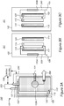
- Figures 3A and 3B are high level schematic illustrations of cell stacks for lithium ion batteries 101, comprising alternating anodes 110, separators 115 and cathodes 120 packaged in pouch cover 102, according to some embodiments of the invention.
- Figure 3A illustrates a schematic plan view along an axis perpendicular to anodes 110 (denoted “A”), separators 115 (denoted “S”) and cathodes 120 (denoted “C”)
- Figure 3B is a side view of anodes 110, separators 115 and cathodes 120.
- An electrolyte 105 (denoted “E") contacts anodes 110 and cathodes 120 in separate compartments, delimited by separators 115, a feature which is not shown in the figures.
- FIGS 3A and 3B illustrate systems 100 and batteries 101, which comprise a lithium metal source 130A within pouch cover 102, having an external contact 131 (e.g., one or more external contact(s) 131 such as metallic tabs) electric circuitry 106 (shown schematically), configured to pre-lithiate 210A (indicated schematically, in relation to SEI formation on anodes 110, and see Figure 1 ) anodes 110 electrochemically, by applying specified voltage between anodes 110 (e.g., via external contacts 111 thereof, indicated schematically as electric connection and voltage application 250 ) and metal ion source 130A in pouch cover 102 (e.g., via external contacts 131 thereof), prior to a formation process 280 of the lithium ion battery (e.g., via external contacts 111, 121 of anode(s) 110 and cathode(s) 120, respectively).
- anodes 110 e.g., via external contacts 111 thereof, indicated schematically as electric connection and voltage application 250
- Formation 280 which does not belong to the present invention, may be followed by degassing 290 and possibly removal of metal ion source 130.
- prelithiation 210A which does not belong to the present invention, results in movement of lithium and/or other metal ions from metal ion source 130 to anode 110, possibly at least partly forming the SEI ( 210A and/or 210B ) and/or preventing or reducing lithium losses from the cathode 210D upon formation and/or operation, under corresponding operation conditions (connecting metal ion source, e.g., lithium source 130 to cathode 120 (see Figure 3C ) and operating electric circuitry 106 during or after formation step 280, when lithium in cathode(s) 120 is depleted).
- Arrow 220 indicated schematically the movement of metal ions (e.g., lithium) to anode 110 to form the SEI (see also Figure 11 ).
- FIG 3C illustrates systems 100 and batteries 101, which comprise lithium source 130A within pouch cover 102, configured to provide additional lithium 210D to cathodes 120 (indicated schematically, in relation to cathodes 120 ), electrochemically, by applying specified voltage between cathodes 120 (e.g., via external contacts 121 thereof) and lithium source 130 (e.g., lithium source) in pouch cover 102 (e.g., via external contacts 131 thereof, see e.g., Figure 3A ), during and/or after formation process 240 of lithium ion battery 101 (e.g., via external contacts 111, 121 of anode(s) 110 and cathode(s) 120, respectively).
- specified voltage between cathodes 120 e.g., via external contacts 121 thereof
- lithium source 130 e.g., lithium source
- Compensating 210D for lithium loss at cathode 120 may be carried out independently or complementarily to pre-lithiation and/or lithiation 210A of anode(s) 110, SEI formation through metal ions 210B and/or lithium supply during operation 210C. Any of anode(s) 110 and cathode(s) 120 may be lithiated in any of the disclosed configurations, sequentially or simultaneously, from same or different metal ion sources 130 (e.g., lithium source, possibly with additional metal sources) and using one or more components of electric circuitry 106. Arrow 240 indicated schematically the movement of lithium ions to cathode 120 to supplant cathode lithium which is fixated in the SEI or otherwise lost (see also Figure 11 ).
- metal ion sources 130 e.g., lithium source, possibly with additional metal sources
- both anode(s) 110 and cathode(s) 120 may be lithiated (and/or provided with metal ions 210B for SEI formation on the anodes) from same or different metal ion source(s) 130, either being carried out externally (as illustrated e.g., in Figures 5A, 5B , 9 and 10 ) and/or internally (see e.g., Figures 6-8 below).
- lithiation 210A and/or provision of metal ions 210B may be carried out fully before formation process 280, lithiation 210A and/or provision of metal ions 210B may be carried out partly before formation process 280, and possibly continue during a first, second and/or later cycles of formation process 280.
- the relative timing, metal ion selection and configuration of metal ion source 130 may be adjusted to optimize the structure of the formed SEI and to improve the stability of batteries 101.
- anode(s) 110 may be pre-lithiated and/or lithiated 210A, and/or cathode(s) 120 may be lithiated 210D using the following embodiments.
- Embodiments referring to anodes 110 may be re-configured to be applicable to cathode(s) 120 and vice versa. Any of the disclosed embodiments may be applied to any electrode in battery 101.
- FIGs 4A-4C are high level schematic illustrations of systems 100 and battery configurations 101 having various metal ion sources 130.
- metal ion source 130 e.g., lithium source
- Figure 4A illustrates schematically one or more elongated metal ion sources 130A (e.g., lithium source) positioned along anodes 110 and Figure 4B illustrates schematically one or more elongated metal ion sources 130A positioned perpendicularly to anodes 110 (SEI formation 215, possibly as a result of lithium ion movements from prelithiation 210A, is indicated schematically by arrows).
- Current collectors 112, 122 are depicted for anode 110 and cathode 120, respectively, e.g., in non-limiting examples, anode current collector 112 may be made of copper and cathode current collector 112 may be made of aluminum.
- Metal ion sources 130 may, in certain embodiments, be used without contacts and application of external voltage to supply metal ions via spontaneous chemical reaction upon contact with anode(s) 110 and/or cathode(s) 120.
- contacts 131 may be connected to metal ion source 130 to provide metal ions to anode(s) 110 and/or cathode(s) 120 electrochemically, in a controllable manner, by application of corresponding voltages between metal ion sources 130 and anode(s) 110 and/or cathode(s) 120.
- Figure 4C illustrates schematically one or more elongated metal ion sources 130A positioned perpendicularly to a cell stack 104 of alternating anodes 110, separators 115 and cathodes 120, cell stack 104 being composed of multiple cells 103, each cell 103 comprising one set of anode 110, separator 115 and cathode 120, with their corresponding current collectors 112, 122, electrolyte 105 and associated structures.
- metal ion source 130A may be spatially associated with one or more anode 110 and/or with one or more cathode 120 of stack 104, and be positioned to optimize the movement of lithium therefrom to anode 110.
- metal ion source 130A may be positioned to minimize a distance to anodes 110, to provide as uniform as possible metal ion movement thereto (e.g., of any of Li + , Mg ++ , Na + etc.), and/or to enhance the stability of the formed SEI.
- Contacts 131 may be connected to metal ion source 130 to provide metal ions to anode(s) 110 and/or cathode(s) 120 electrochemically, in a controllable manner, by application of corresponding voltages between metal ion sources 130 and anode(s) 110 and/or cathode(s) 120.
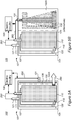
- FIGS 5A and 5B are high level schematic illustrations of systems 100 and battery configuration 101 having removable metal ion sources 130, according to some embodiments of the invention.
- metal ion source 130 may be configured to be removable from pouch cover 102 during degassing 290 of battery 101 following formation process 280.
- metal ion sources 130 may be part of a tab 102A of pouch 102 which is separable from the main body of pouch 102, e.g., along a tearing line 135, as illustrated schematically in Figures 5A and 5B .
- removal of metal ion source 130 may be carried out during degassing 290 (e.g., removal of wire-shaped metal ion source 130 through a degassing hole) and does not require an additional process stage.
- Figures 5A and 5B further illustrate various, non-limiting configurations of shapes and proportions of metal ion source 130, such as e.g., any of a strap, a rod or a bar ( Figure 5A ), T shape, L shape and triangle (illustrated as alternatives in Figure 5B , all attached to tab 131 ), all not belonging to the present invention, which may have different orientations and possibly multiple tabs 131, to improve any of the prelithiation process, its kinetics, and the homogeneity of the resulting surface of the anode.
- Cathode lithiation 210D may be carried out in similar configurations, operated during or after formation, with respect to lithium-depleted cathodes. Applying the specified voltage between anodes 110 and contact(s) 131 of metal ion source 130 - illustrated as a non-limiting example, may be modified to lithiate cathode 120 via contacts 121 - are indicated schematically as electric connection and voltage application 250.
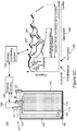
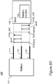
- Figures 5C and 5D are high level schematic illustrations of system and battery configurations for lithiation during operation, according to some embodiments of the invention.
- Figure 5C illustrates schematically effects of lithiation during operation on the battery's SoH during operation
- Figure 5D illustrates schematically control parameters over lithiation during operation, as described below.
- lithiation may be carried out during operation stages 340.
- additional lithium may be provided into the cell during operation to compensate for depletion of lithium in the cell during various processes involved in operation 340, such as charging and/or discharging cycles in which lithium may be consumed by further SEI formation, electrolyte decomposition, lithium fixation in the anode and/or in the cathode etc.
- Contact 131 may be operated with respect to contacts 111 and/or 121 of anodes 110 and cathodes 120, respectively, to deliver additional lithium into the cell in a pre-programed fashion (e.g., a certain amount after every certain number of cycles) and/or under specified circumstance - such as e.g., indications of a battery management system (BMS) 108 associated with battery 101 of specified declines in capacity, increases in resistance, or any other state of health (SoH) parameters.
- BMS battery management system
- Pulses of lithiation 345 are shown schematically in Figure 5C to illustrate schematically the reduction in capacity decline of the battery due to applied lithiation 345, leading to increased lifetime, which may reach 50%, 100% or even more with respect to the lifetime of battery 101 without lithiation pulses 345 during operation 340. It is noted that lithiation during operation 340 may be carried out continuously, on-demand and/or in a pulsed patterned, the latter mode illustrated in a non-limiting manner in Figure 5C .
- Systems 100 may comprise a cell stack for lithium ion batteries 101, comprising alternating anodes 110, separators 115 and cathodes 120 packaged in pouch cover 102 (the anodes and cathodes being electrodes of the cell stack), lithium source 130 within pouch cover 102, having external contact 131 and being in fluid communication with anodes 110, and electric circuitry 106, configured to lithiate, electrochemically, anodes 110 by applying specified voltage between anodes 110 and lithium source 130 in pouch cover 102 via its contact 131, during operation of lithium ion battery 101 and controllably with respect to a state of health (SoH) thereof.
- SoH state of health
- systems 100 may comprise a cell stack for lithium ion batteries 101, comprising alternating anodes 110, separators 115 and cathodes 120 packaged in pouch cover 102 (the anodes and cathodes being electrodes of the cell stack), lithium source 130 within pouch cover 102, having external contact 131 and being in fluid communication with cathodes 120, and electric circuitry 106, configured to lithiate, electrochemically, cathodes 120 by applying specified voltage between cathodes 120 and lithium source 130 in pouch cover 102 via its contact 131, during operation of lithium ion battery 101 and controllably with respect to a state of health (SoH) thereof.
- SoH state of health
- systems 100 are configured to lithiate anodes 110 and/or cathode(s) 120 selectively, according to SoH parameters of battery 101 (e.g., specified voltage drop, specified capacity fade, specified rise in resistance, specified energy throughput - any of which with respect to predefined thresholds.
- SoH parameters of battery 101 e.g., specified voltage drop, specified capacity fade, specified rise in resistance, specified energy throughput - any of which with respect to predefined thresholds.
- contacts 111, 121, 131 of anodes 110, cathodes 120 and lithium source 130, respectively may be used for operating battery 101, lithiating anodes 110 and/or cathodes 120 (denoted as stages 210A, 210D, respectively, by delivering lithiation pulses 345 ) as well as monitoring anodes 110 and/or cathodes 120 with respect to lithium source 130 (indicated as stages 347A, 347B, respectively).
- Either or both electric circuitry 106 or of BMS 108 may perform or be involved in any of these functions.
- electric circuitry 106 may be realized as part of BMS 108 (as illustrated e.g., in Figure 5D ).
- electric circuitry 106 may be separated from BMS 108 and in communication therewith (as illustrated e.g., in Figure 5C ). Any of these configurations may be applicable in any of the embodiments presented above.
- systems 100 may comprise BMS 108, configured to monitoring the SoH of lithium ion battery 101 and to control electric circuitry 106 to carry out the lithiating upon detected specified decrease in the SoH.
- BMS 108 may be further configured to distinguish, based on the monitored SoH, if anodes 110 or cathodes 120 are to be lithiated as the at least one of the electrodes, and to control electric circuitry 106 accordingly.
- BMS 108 may be further configured to measure a voltage between lithium source 130 and anodes 110 after charging (indicated schematically be arrow 347A ) and/or cathodes 120 after discharging (indicated schematically be arrow 347B ), and to control electric circuitry 106 accordingly.
- BMS 108 may be configured to lithiate any of anodes 110 or cathodes 120, according to any specified criterion, and at any stage of charging or discharging.
- FIG. 6 is a high level schematic illustration of battery configuration 101 , not belonging to the present invention, having metal ion sources 130A (e.g., lithium sources) as beads adjacent to anode(s) 110, according to some embodiments of the invention.
- Metal ion source 130A e.g., lithium source
- Metal ion source 130A may comprise any number of beads, positioned in cells 103 and stacks 104, and may have any form.
- metal ion source 130A may comprise beads positioned adjacent or onto anode(s) 110.
- metal ion source beads 130A may be left in battery 101 during operation, and provide additional lithium supply to increase cycle life by providing lithium which is consumed internally during operation.
- metal ion source beads 130A may be removed, e.g., during degassing 290 (possibly preferentially with respect to the type of metal). It is noted that in case of metal ion source as beads or other small elements within pouch 102, prelithiation may be carried out electrochemically on the surface of anode 110 without establishment of an external electrical circuit (e.g., without tab(s) 131 ).
- Metal ion sources 130 may, in certain embodiments, be used without contacts and application of external voltage to supply metal ions via spontaneous chemical reaction upon contact with anode(s) 110 and/or cathode(s) 120.
- contacts 131 may be connected to metal ion source 130 to provide metal ions to anode(s) 110 and/or cathode(s) 120 electrochemically, in a controllable manner, by application of corresponding voltages between metal ion sources 130 and anode(s) 110 and/or cathode(s) 120.
- FIGS 7A and 7B are high level schematic illustrations of battery configuration 101 , not belonging to the present invention, having metal ion sources 130A which are incorporated in current collector(s) 112, 122, according to some embodiments of the invention.
- metal ion source beads 130A may be incorporated in one or more of anode and/or cathode in current collector(s) 112, 122, respectively.
- cathode current collector(s) 122 are adjacent to anode(s) 110 of adjacent cell 103, so that incorporation of metal ion source 130A in cathode current collector(s) 122 may provide close lithium movement paths to anode(s) 110 in adjacent cells 103.
- incorporation of metal ion source 130A in current collector(s) 112 and/or 122 may be carried out by mixing and/or alloying lithium in current collector material, such as lithium copper mixture and/or alloy for anode current collector(s) 112 and/or as lithium aluminum mixture and/or alloy for cathode current collector(s) 122.
- Metal ion sources 130 may, in certain embodiments, be used without contacts and application of external voltage to supply metal ions via spontaneous chemical reaction upon contact with anode(s) 110 and/or cathode(s) 120.
- contacts 131 may be connected to metal ion source 130 to provide metal ions to anode(s) 110 and/or cathode(s) 120 electrochemically, in a controllable manner, by application of corresponding voltages between metal ion sources 130 and anode(s) 110 and/or cathode(s) 120.
- metal ion source 130A within batteries 101 may be combined to form additional embodiments.
- any of the embodiments disclosed herein may be applied for any configuration of cell stacks 104, and while most illustrations present single cells 103 with one anode 110 and one cathode 120, this is done solely for explanatory purposes, and is not limiting the application of the invention to full cell stacks 104 and corresponding batteries 101.
- Figure 8 is a high level schematic illustration of system configuration 100, not belonging to the present invention, with fluid flow regulation of metal ion levels in one or more electrode, with flows indicated as inflow 140 and outflow 145, according to some embodiments of the invention.
- regulation of metal ion levels may be carried out from external metal ion source 130B (shown schematically) by fluid provision 140 of lithium and/or any of Mg, Na, Mg ++ , Na + etc., which may be used to continuously replace electrolyte 105 prior, or during formation process 280.
- the regulation of metal ion levels may comprise pre-lithiation 210A (see Figure 1 ) of anodes 110 and/or provision of metal ions 210B (see Figure 1 ) to anodes 110. In either case, provided Li, Mg, Na, Li + , Mg ++ and/or Na + may contribute to the formation of SEI on anode(s) 110.
- the regulation of metal ion levels may comprise lithiation 210D (see Figure 1 ) of cathodes 120 after or during formation steps.
- FIGS 9 and 10 are high level schematic illustrations of systems 100 with fluid flow regulation of metal ion levels in one or more electrode, with flows indicated as inflow 140 and outflow 145, according to some embodiments of the invention.
- System 100 may comprise at least one cell stack 104 for lithium ion batteries 101, each cell stack 104 comprising alternating anodes 110, separators 115 and cathodes 120 packaged in pouch cover 102, at least one electrolyte reservoir 160, having metal ion source(s) therein (e.g., in fluid 165 such as in electrolyte fluid), in fluid connection to cell stack(s) 104 in respective pouch cover 102, a pump 150 configured to maintain circular flow 140, 145 of electrolyte 165 between cell stack(s) 104 in pouch cover 102 and electrolyte reservoir 160, and electric circuitry 106 configured to apply specified voltage between anode(s) 110 of cell stack(s) 104 and the metal ion source(s) (comprising any of Li, Mg, Na,
- the regulation of metal ion levels may comprise pre-lithiation 210A (see Figure 1 ) of anodes 110 and/or provision of metal ions 210B (see Figure 1 ) to anodes 110. In either case, provided Li, Mg, Na, Li + , Mg ++ and/or Na + may contribute to the formation of SEI on anode(s) 110.
- the regulation of metal ion levels may comprise limitation 210D (see Figure 1 ) of cathodes 120 after or during formation steps.
- Applying the specified voltage between anodes 110 and contact(s) 131 of metal ion source 130B - illustrated as a non-limiting example, may be modified to lithiate cathode 120 via contacts 121 - are indicated schematically as electric connection and voltage application 250.
- electrolyte reservoir 160 may comprise at least two electrolyte reservoirs 160, 162, of which at least one ( 160 ) may be configured to regulate metal ion levels ( 210B ) and/or to pre-lithiate 210A (and/or provide metal ions to) anodes 110 and form the SEI thereon, and at least another one ( 162 ) may be configured to load pouch cover 102 with electrolyte 105 for operation of lithium ion battery 101 after pre-lithiation 210A, possibly after formation 280. Formation process 280 may be carried out during or after the metal ions are regulated 210B, e.g., during prelithiation 210A and/or after prelithiation 210A is completed.
- Different, possibly multiple electrolyte reservoir 160, 162 may be used to provide different types and/or proportions of metal ions, possibly in different pre-lithiation and/or formation steps.
- cell stack(s) 104 may comprise multiple cell stacks 104 in multiple batteries 101, and electrolyte reservoir(s) 160, 162 may be used simultaneously and commonly for all cell stacks 104 to carry out the regulation of metal ion levels and possibly electrolyte replacement.
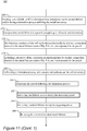
- Figure 11 is a high-level flowchart illustrating a method 200 , not belonging to the present invention.
- the method stages may be carried out with respect to systems 100 and batteries 101 described above, which may optionally be configured to implement method 200.
- Method 200 may comprise stages for producing, preparing and/or using systems 100 and batteries 101, such as any of the following stages, irrespective of their order.
- Certain embodiments comprise computer program products comprising a computer readable storage medium having computer readable program embodied therewith and configured to carry out of the relevant stages of method 200.
- Method 200 may comprise stages for producing, preparing, operating, and/or using systems 100 and batteries 101 described above, such as any of the following stages, irrespective of their order.
- Method 200 comprises regulating a level of metal ions in at least one electrode (e.g., anode(s) and/or cathode(s)) in a lithium ion battery, when the at least one electrode is in a pouch of the lithium ion battery (stage 210 ), wherein the regulation of metal ions level is carried out electrochemically between the at least one electrode and a metal ion source which is an internal and/or an external metal ions source containing e.g., Li, Mg and/or Na (stage 212 ), prior to, and possibly during a formation process of the lithium ion battery, and possibly prior to and/or during the operation of the battery (stage 213 ).
- a metal ion source which is an internal and/or an external metal ions source containing e.g., Li, Mg and/or Na
- Regulating the metal ion levels may be carried out in situ, within the battery pouch, on anode(s) and/or cathode(s) of a cell stack, sequentially or simultaneously, from a metal ion source internal, in the pouch.
- Certain embodiments of providing metal ions to the anodes before the formation process is carried out may be referred to as a pre-metallization stage.
- Metal ions such as Mg ++ and Na + may be provided, possibly in addition to Li + , as well as metal atoms e.g., Li, Mg, Na.
- regulation 210 may comprise any of the following: pre-lithiating the anodes (as the electrodes, the anodes may comprise anode material particles of at least one of Si, Ge and Sn which may be polymer-coated) from the at least one lithium source (as the metal ion source) prior to the formation process (stage 220 ); lithiating the anodes from the at least one lithium source during the formation process (stage 225 ), and possibly also during operation from at least rudiments of the at least one lithium source which are left in the pouch during operation (stage 227 ); forming at least part of the SEI on the anodes from magnesium and/or sodium from the at least one magnesium and/or sodium source (as the metal ion source, possibly in combination with lithium), at least prior to the formation process (stage 230 ); and/or lithiating the cathodes (as the electrodes) from the at least one lithium source (as the metal ion source) upon lithium depletion from the cathodes
- Method 200 may comprise connecting, electrically, electrode(s) to the metal ion source and applying a voltage therebetween (stage 250 ).
- Pre-lithiating and/or lithiating the anodes may be carried out by electrically connecting the anode(s) to the metal ion source and applying a voltage therebetween.
- Lithiating the cathodes may be carried out by electrically connecting the at least one cathode (when it is a depleted state, having part of its original lithium content) to the metal ion source and applying a voltage therebetween.
- Pre-lithiating and/or lithiation of the anode(s) 220, 225, respectively, may be configured to at least partly form, controllably, an SEI on the anode(s), during a pre-lithiation, pre-metallization (referring e.g., to provision of Mg and/or Na ions, alone or in addition to Li ions) and/or during the formation process, utilizing the metal ion source (stage 260 ).
- lithiating 225 may be configured to compensate for lithium consumption during the formation process, e.g., from the cathode(s) - for example by adding lithium to the cathode 240 during the formation process, from the lithium source.
- Method 200 may further comprise incorporating metal lithium in a pouch comprising a cell stack and electrolyte (stage 270 ) and carrying out any of stages 210 to 240 using the internal lithium source, at least partly.
- method 200 may comprise pre-lithiating anode(s) of the cell stack electrochemically by electric connection thereof to the metal lithium (and/or Mg, Na, etc.) incorporated in the pouch (stage 272 ) and/or lithiating cathode(s) of the cell stack electrochemically by electric connection thereof to the metal lithium (and/or Mg, Na, etc.) incorporated in the pouch (stage 274 ).
- Method 200 may further comprise performing the formation process, with anodes and cathodes as the cell electrodes (stage 280 ). Method 200 may further comprise degassing the pouch following the formation process (stage 290 ). Method 200 may further comprise removing the metal ion source after pre-lithiation 210 during degassing phase 250 following formation process 240 (stage 292 ). In certain embodiments, method 200 may comprise removing residual lithium during the degassing phase (stage 294 ), and possibly re-using the removed residual metal lithium (stage 296 ).
- Anode pre-lithiation 220 may be carried out prior to formation process 280 (stage 302 ) and/or anode lithiation 225 may be carried out during formation process 280 (stage 304 ). It is noted that lithiation during the formation process may augment pre-lithiation applied before the formation process. Additional lithiation during the formation process may be configured to compensate for lithium consumption during the formation process, e.g., from the cathode(s).
- Method 200 may further comprise optimizing a shape and/or a position of the metal ion source within the pouch (stage 310 ), possibly optimizing a position of the metal ion source in the stack, according to the efficiency of metal ions movement (stage 315 ), e.g., with respect to pre-lithiation 220, and/or metal ion regulation and/or lithiation of any of stages 225-240.
- Method 200 may comprise associating, at least partly, the metal ion and/or lithium source with the anode(s) in the stack (stage 320 ) and/or with the cathode(s) in the stack (stage 322 ).
- method 200 may comprise incorporating metal lithium, as a lithium source, and/or other metal mixtures or alloys of e.g., Mg, Na, Li, in at least one current collector (stage 330 ), e.g., in at least one anode current collector and/or in at least one cathode current collector, e.g., in mixture with copper and/or as a copper alloy in the former case, and/or in mixture with aluminum and/or as an aluminum alloy in the latter case.
- Method 200 may comprise incorporating metal lithium in a small quantity in the pouch, without removal thereof from the pouch (stage 335 ). Incorporated lithium may be thus used to at least partly compensate for losses of lithium during operation of the battery.
- Method 200 may comprise operating the lithium ion battery (stage 340 ).
- Method 200 may comprise incorporating metal lithium in wire form in the pouch and carrying out lithiation during operation (stage 342 ), to compensate for depletion of lithium in the cell during various processes involved in operation, such as charging and/or discharging cycles in which lithium may be consumed by further SEI formation, electrolyte decomposition, lithium fixation in the anode and/or in the cathode etc.
- Lithiation 342 may be continuous or intermittent, and possibly be related to SoH parameters of the battery (stage 345 ).
- Method 200 may further comprise monitoring the SoH of the lithium ion battery and carrying out the lithiating upon detected specified decrease in the SoH (stage 347 ), e.g., using SoH parameters such as reduction in capacity, rise in resistance, decreasing maximal voltage etc.).
- monitoring 347 may comprise either or both monitoring the anodes and monitoring the cathodes with respect to lithium source itself (see e.g., Figure 5D ), e.g., by measuring the anodes and/or cathodes with respect to the lithium source (stage 348 ).
- Method 200 may further comprise lithiating anodes after charging and/or cathodes after discharging of the cell (stage 349 ), or possibly during partial charging and/or discharging, respectively.
- the selection of anodes and/or cathodes for lithiation may be carried out according to a voltage level between the anodes and the lithium source after the charging and/or according to a voltage level between the cathodes and the lithium source after the discharging.
- Method 200 may comprise positioning the metal ion source along and/or perpendicularly to a cell stack of the battery (stage 350 ). In certain embodiments, method 200 may comprise positioning the metal ion source in a removable part of the pouch (stage 352 ). In certain embodiments, method 200 may comprise associating, spatially, the metal ion source with opening(s) for degassing (stage 355 ).
- Method 200 may comprise connecting electrolyte reservoir(s), having metal ion source therein, in fluid connection to the cell stack in the pouch cover (stage 360 ) and carrying out any of the metal ion regulation stages via the fluid connection.
- method 200 may comprise pumping electrolyte between the reservoir(s) and the cell stacks in the pouches (stage 365 ), possibly with different electrolyte reservoir(s) providing different electrolyte compositions, such as one or more electrolyte compositions for pre-lithiation, for SEI formation, for consequent lithiation, for filling operative electrolyte for the operation cycles etc.
- method 200 may comprise maintaining circular flow of electrolyte between the cell stack in the pouch cover and the electrolyte reservoir(s) (stage 370 ), see e.g., flows 140, 145 in Figures 9 and 10 .
- Method 200 may further comprise applying specified voltage between the anodes and the metal ion source in the electrolyte reservoir(s) (stage 380 ).
- Method 200 may further comprise configuring at least one electrolyte reservoir to provide the pre-lithiation and at least another electrolyte reservoir to load the pouch cover with electrolyte for operation of the lithium ion battery (stage 390 ).
- Method 200 may comprise applying the metal ion regulation (e.g., pre-lithiation and/or lithiation) simultaneously to multiple cell stacks with the electrolyte reservoir(s) used commonly for all the cell stacks (stage 400 ).
- regulation of metal ions level 210 may be carried out in any of constant current (CC), constant voltage (CV), and/or constant current, constant voltage (CCCV) modes, as well as in dynamic current (dI / dt ⁇ 0) and/or dynamic voltage (dV / dt ⁇ 0) modes alone or in combination.
- Currents may range from 10 ⁇ A to 10mA and voltage may vary from 400mV to 20mV.
- Prelithiation time may be in scales of a few hours to a few weeks.
- Temperature may vary from 25°C to 70°C.
- anode(s) 110 may comprise anode active material particles and additive(s) such as binder(s) (e.g., polyvinylidene fluoride (PVDF), styrene butadiene rubber (SBR) or any other binder), plasticizer(s) and/or conductive filler(s), mixed in water-based or organic solvent(s).
- binder(s) e.g., polyvinylidene fluoride (PVDF), styrene butadiene rubber (SBR) or any other binder
- plasticizer(s) and/or conductive filler(s) mixed in water-based or organic solvent(s).
- the anode slurry may be dried, consolidated and positioned in contact with current collector 112.
- Anode active material particles may comprise particles of any of graphite, graphene, metalloids such as silicon, germanium and/or tin, and/or possibly particles of aluminum, lead and/or zinc.
- Anode active material particles may be configured to receive lithium during charging and release lithium during discharging, reversibly over a large number of cycles, without mechanical damage to anode(s) 110.
- the anode active material particles may be composite materials, e.g., coated particles, shell-core particles etc.
- the anode active material particles may comprise coatings such as conductive polymers, lithium polymers, possibly borate and/or phosphate salt(s) (forming e.g., B 2 O 3 , P 2 O 5 etc.
- anode active material particles on the surface of anode active material particles), bonding molecules which may interact with electrolyte 105 (and/or ionic liquid additives thereto) and/or various nanoparticles (e.g., B 4 C, WC, VC, TiN) which may be attached to the anode material particles in anode preparation processes such as ball milling.
- the size range of the anode active material particles may be at an order of magnitude of 100nm, and/or possibly in the order of magnitude of 10nm or 1 ⁇ .
- the size range of nanoparticles attached to the anode active material particles may be at an order of magnitude lower than that of the anode material particles, e.g., lOnm, and/or possibly 100nm (the latter in case of larger anode material particles).
- cathode(s) 120 may comprise materials based on layered, spinel and/or olivine frameworks, and comprise various compositions, such as LCO formulations (based on LiCoO 2 ), NMC formulations (based on lithium nickel-manganese-cobalt), NCA formulations (based on lithium nickel cobalt aluminum oxides), LMO formulations (based on LiMn 2 O 4 ), LMN formulations (based on lithium manganese-nickel oxides) LFP formulations (based on LiFePO 4 ), lithium rich cathodes, and/or combinations thereof.
- Separator(s) 115 may comprise various materials, such as polyethylene (PE), polypropylene (PP) or other appropriate materials.
- electrolyte 105 may comprise liquid electrolytes such as ethylene carbonate (EC), diethyl carbonate (DEC), propylene carbonate (PC), fluoroethylene carbonate (FEC), ethyl methyl carbonate (EMC), dimethyl carbonate (DMC), vinylene carbonate (VC), possibly tetrahydrofuran (THF) and/or its derivatives, and combinations thereof; and/or solid electrolytes such as polymeric electrolytes such as polyethylene oxide, fluorine-containing polymers and copolymers (e.g., polytetrafluoroethylene), and combinations thereof.
- liquid electrolytes such as ethylene carbonate (EC), diethyl carbonate (DEC), propylene carbonate (PC), fluoroethylene carbonate (FEC), ethyl methyl carbonate (EMC), dimethyl carbonate (DMC), vinylene carbonate (VC), possibly tetrahydrofuran (THF) and/or its derivatives, and combinations thereof.
- Electrolyte 105 may comprise lithium electrolyte salt(s) such as LiPF 6 , LiBF 4 , lithium bis(oxalato)borate, LiN(CF 3 SO 2 ) 2 , LiN(C 2 F 5 SO 2 ) 2 , LiAsF 6 , LiC(CF 3 SO 2 ) 3 , LiClO 4 , LiTFSI, LiB(C 2 O 4 ) 2 , LiBF 2 (C 2 O 4 ), tris(trimethylsilyl)phosphite (TMSP) and combinations thereof.
- Ionic liquid(s) additives may be added to electrolyte 105.
- Figure 12 provides an example of results illustrating the improved operation of batteries 101 resulting from systems 100 and/or methods 200, according to some embodiments of the invention.
- Figure 12 illustrates schematically a charging curve (solid line) and discharging curves of a first cycle, for prior art full cell (dotted line) and for full cell 101 (dashed line) with pre-lithiated anode.
- the capacity loss full cycle equivalent, FCE is improved from ca. 28% (leaving ca. 72% capacity) in the prior art full cell (dotted line) to ca. 11% (leaving ca. 89% capacity) in full cell 101 with pre-lithiated anode (dashed line).
- Certain embodiments comprise computer program products comprising a computer readable storage medium having computer readable program embodied therewith and configured to monitor, control and/or operate systems 100 and batteries 101 to provide the regulation of metal ions and/or lithiation steps described above, such as pre-lithiation, lithiation during formation and/or lithiation during operation, possibly in conjuncture with the carrying out of the formation processes and/or operating batteries 101.
- Certain embodiments comprise battery management systems comprising computer readable program configured to operate any of the method stages disclosed above.
- These computer program instructions may also be stored in a computer readable medium that can direct a computer, other programmable data processing apparatus, or other devices to function in a particular manner, such that the instructions stored in the computer readable medium produce an article of manufacture including instructions which implement the function/act specified in the flowchart and/or portion diagram or portions thereof.
- the computer program instructions may also be loaded onto a computer, other programmable data processing apparatus, or other devices to cause a series of operational steps to be performed on the computer, other programmable apparatus or other devices to produce a computer implemented process such that the instructions which execute on the computer or other programmable apparatus provide processes for implementing the functions/acts specified in the flowchart and/or portion diagram or portions thereof.
- each portion in the flowchart or portion diagrams may represent a module, segment, or portion of code, which comprises one or more executable instructions for implementing the specified logical function(s).
- the functions noted in the portion may occur out of the order noted in the figures. For example, two portions shown in succession may, in fact, be executed substantially concurrently, or the portions may sometimes be executed in the reverse order, depending upon the functionality involved.
- each portion of the portion diagrams and/or flowchart illustration, and combinations of portions in the portion diagrams and/or flowchart illustration can be implemented by special purpose hardware-based systems that perform the specified functions or acts, or combinations of special purpose hardware and computer instructions.
- an embodiment is an example or implementation of the invention.
- the various appearances of "one embodiment”, “an embodiment”, “certain embodiments” or “some embodiments” do not necessarily all refer to the same embodiments.
- various features of the invention may be described in the context of a single embodiment, the features may also be provided separately or in any suitable combination.
- the invention may also be implemented in a single embodiment.
- Certain embodiments of the invention may include features from different embodiments disclosed above, and certain embodiments may incorporate elements from other embodiments disclosed above.
- the disclosure of elements of the invention in the context of a specific embodiment is not to be taken as limiting their use in the specific embodiment alone.
Landscapes
- Engineering & Computer Science (AREA)
- Chemical & Material Sciences (AREA)
- General Chemical & Material Sciences (AREA)
- Manufacturing & Machinery (AREA)
- Chemical Kinetics & Catalysis (AREA)
- Electrochemistry (AREA)
- Materials Engineering (AREA)
- Physics & Mathematics (AREA)
- General Physics & Mathematics (AREA)
- Secondary Cells (AREA)
- Microelectronics & Electronic Packaging (AREA)
- Battery Electrode And Active Subsutance (AREA)
- Charge And Discharge Circuits For Batteries Or The Like (AREA)
Claims (15)
- Verfahren, umfassend ein Lithiieren von Elektroden einer Lithiumionenbatterie während ihres Betriebs, das auf elektrochemischem Weg zwischen den Elektroden und einer in die Batterie eingebetteten Lithiumquelle und in Bezug auf einen Gesundheitszustand (State of Health - SoH)) der Lithiumionenbatterie steuerbar ausgeführt wird, wobei das Verfahren ferner umfasst:
Aufnehmen der Lithiumquelle, die einen mit ihr verbundenen elektrischen Kontakt aufweist, innerhalb eines Etuis der Lithiumionenbatterie, wobei die Elektroden Anoden und/oder Kathoden der Lithiumionenbatterie umfassen und wobei die Lithiumquelle als lithiumhaltiger Draht konfiguriert ist, der dem Etui zugeordnet ist und mit den Anoden und/oder Kathoden in Fluidverbindung steht. - Verfahren nach Anspruch 1, ferner umfassend ein Regulieren eines Gehalts an Metallionen in den Anoden vor und/oder während eines Bildungsprozesses der Lithiumionenbatterie.
- Verfahren nach Anspruch 1, ferner umfassend ein Überwachen des SoH der Lithiumionenbatterie und ein Durchführen des Lithiierens, wenn eine spezifizierte Abnahme des SoH erfasst wird.
- Verfahren nach Anspruch 3, wobei das Überwachen des SoH der Batterie ein Messen einer Anoden- und/oder Kathodenlithiierung unter Verwendung der Lithiumquelle umfasst.
- Verfahren nach einem der vorhergehenden Ansprüche, wobei das Lithiieren ein Lithiieren der Anoden nach einem Laden der Batterie umfasst.
- Verfahren nach einem der vorhergehenden Ansprüche, wobei das Lithiieren gemäß einem Spannungspegel zwischen den Anoden und der Lithiumquelle nach dem Laden ausgeführt wird.
- Verfahren nach einem der vorhergehenden Ansprüche, wobei das Lithiieren ein Lithiieren der Kathoden nach einem Entladen der Batterie umfasst.
- Verfahren nach einem der vorhergehenden Ansprüche, wobei das Lithiieren gemäß einem Spannungspegel zwischen den Kathoden und der Lithiumquelle nach dem Entladen ausgeführt wird.
- System, umfassend:einen Zellenstapel, der eine Lithiumionenbatterie bildet, umfassend alternierende Anoden, Separatoren und Kathoden, die in einer Etuiabdeckung verpackt sind, wobei die Anoden und Kathoden Elektroden des Zellenstapels sind,eine Lithiumquelle innerhalb der Etuiabdeckung, die einen externen Kontakt aufweist und in Fluidverbindung mit mindestens einer der Elektroden steht, wobei die Lithiumquelle als lithiumhaltiger Draht konfiguriert ist, der dem Etui zugeordnet ist und mit den Anoden und/oder Kathoden in Fluidverbindung steht, undeine elektrische Schaltung, die dazu konfiguriert ist, durch Anlegen einer spezifizierten Spannung zwischen der mindestens einen der Elektroden und der Lithiumquelle in der Etuiabdeckung über ihren Kontakt während eines Betriebs der Lithiumionenbatterie und steuerbar in Bezug auf einen Gesundheitszustand (SoH) die mindestens eine der Elektroden auf elektrochemischem Weg zu lithiieren.
- System nach Anspruch 9, wobei der lithiumhaltige Draht in Fluidverbindung mit mindestens einer der Elektroden steht und die Anoden umfasst.
- System nach Anspruch 9 oder 10, wobei der lithiumhaltige Draht in Fluidverbindung mit mindestens einer der Elektroden steht und die Kathoden umfasst.
- System nach einem der Ansprüche 9 bis 11, ferner umfassend ein Batterieüberwachungssystem (Battery Monitoring System - BMS), das dazu konfiguriert ist, den Gesundheitszustand (SoH) der Lithiumionenbatterie zu überwachen und die elektrische Schaltung zu steuern, sodass sie das Lithiieren nach einer erfassten, spezifizierten Abnahme der SoH ausführt.
- System nach Anspruch 12, wobei das BMS ferner dazu konfiguriert ist, basierend auf dem überwachten SoH zu erfassen, welche der Elektroden zu lithiieren ist und die elektrische Schaltung entsprechend zu steuern.
- System nach Anspruch 12 oder 13, wobei das BMS ferner dazu konfiguriert ist, basierend auf dem überwachten SoH zu unterscheiden, ob Anoden oder Kathoden als die mindestens eine der Elektroden zu lithiieren sind und die elektrische Schaltung entsprechend zu steuern.
- System nach einem der Ansprüche 12 bis 14, wobei das BMS ferner dazu konfiguriert ist, eine Spannung zwischen der Lithiumquelle und den Anoden nach einem Laden und/oder den Kathoden nach einem Entladen zu messen und die elektrische Schaltung entsprechend zu steuern.
Applications Claiming Priority (1)
| Application Number | Priority Date | Filing Date | Title |
|---|---|---|---|
| US15/706,835 US20190089015A1 (en) | 2017-09-18 | 2017-09-18 | In-operation lithiation according to soh monitoring |
Publications (2)
| Publication Number | Publication Date |
|---|---|
| EP3457484A1 EP3457484A1 (de) | 2019-03-20 |
| EP3457484B1 true EP3457484B1 (de) | 2020-06-10 |
Family
ID=63637812
Family Applications (1)
| Application Number | Title | Priority Date | Filing Date |
|---|---|---|---|
| EP18194939.7A Active EP3457484B1 (de) | 2017-09-18 | 2018-09-17 | Lithiierung während des betriebs nach soh-überwachung |
Country Status (4)
| Country | Link |
|---|---|
| US (1) | US20190089015A1 (de) |
| EP (1) | EP3457484B1 (de) |
| JP (1) | JP2019053990A (de) |
| CN (1) | CN109524730A (de) |
Families Citing this family (4)
| Publication number | Priority date | Publication date | Assignee | Title |
|---|---|---|---|---|
| US11152602B2 (en) | 2017-01-12 | 2021-10-19 | StoreDot Ltd. | Using formation parameters to extend the cycling lifetime of lithium ion batteries |
| US11088402B2 (en) | 2017-01-12 | 2021-08-10 | StoreDot Ltd. | Extending cycling lifetime of fast-charging lithium ion batteries |
| DE102019216015A1 (de) * | 2019-10-17 | 2021-04-22 | Robert Bosch Gmbh | Verfahren zum Anpassen einer Anodenüberspannung einer Lithium-Ionen-Batterie, Verfahren zum Verbessern eines Kapazitätsalterungszustands der Lithium-Ionen-Batterie |
| CN113078364A (zh) * | 2021-03-29 | 2021-07-06 | 中南大学 | 一种高能量密度铝壳锂离子电池的制造方法 |
Family Cites Families (21)
| Publication number | Priority date | Publication date | Assignee | Title |
|---|---|---|---|---|
| US20040137326A1 (en) * | 2002-11-09 | 2004-07-15 | Munshi M. Zafar A. | Lithium ion battery and methods of manufacturing same |
| US7662509B2 (en) * | 2004-10-29 | 2010-02-16 | Medtronic, Inc. | Lithium-ion battery |
| JP4910423B2 (ja) * | 2006-02-27 | 2012-04-04 | ソニー株式会社 | バッテリパック、電子機器、およびバッテリ残量検出方法 |
| US8119269B2 (en) * | 2007-05-10 | 2012-02-21 | Enovix Corporation | Secondary battery with auxiliary electrode |
| KR101502440B1 (ko) * | 2007-07-12 | 2015-03-13 | 에이일이삼 시스템즈 인코포레이티드 | 리튬 이온 배터리용 다기능 혼합 금속 감람석 |
| US8163410B2 (en) * | 2007-09-14 | 2012-04-24 | A123 Systems, Inc. | Lithium rechargeable cell with reference electrode for state of health monitoring |
| US20120045670A1 (en) * | 2009-11-11 | 2012-02-23 | Amprius, Inc. | Auxiliary electrodes for electrochemical cells containing high capacity active materials |
| US20130149602A1 (en) * | 2010-01-06 | 2013-06-13 | Etv Energy Ltd | Lithium-ion secondary electrochemical cell and method of making lithium-ion secondary electrochemical cell |
| JP5574115B2 (ja) * | 2011-03-14 | 2014-08-20 | 三菱自動車工業株式会社 | リチウムイオン電池の状態管理方法 |
| JP5894394B2 (ja) * | 2011-08-22 | 2016-03-30 | 株式会社日立製作所 | 二次電池制御システム |
| JP6148879B2 (ja) * | 2013-02-28 | 2017-06-14 | 旭化成株式会社 | 二次電池の電池状態推定装置及び電池パックの製造方法並びにセルバランス確認方法 |
| JP6294348B2 (ja) * | 2013-03-11 | 2018-03-14 | エルジー・ケム・リミテッド | リチウムのプレドーピング方法、この方法を含むリチウム二次電池の製造方法、及びこの製造方法により製造されたリチウム二次電池 |
| US9379418B2 (en) * | 2013-06-20 | 2016-06-28 | Hrl Laboratories, Llc | Battery with reference electrode for voltage monitoring |
| WO2015040685A1 (ja) * | 2013-09-18 | 2015-03-26 | 株式会社日立製作所 | リチウムイオン二次電池用セパレータ、リチウムイオン二次電池用セパレータを用いたリチウムイオン二次電池、および、リチウムイオン二次電池モジュール |
| JP2016076358A (ja) * | 2014-10-06 | 2016-05-12 | 株式会社日立製作所 | リチウムイオン二次電池及び電池システム |
| JP2016091613A (ja) * | 2014-10-30 | 2016-05-23 | 株式会社日立製作所 | 電池システム及び容量回復方法 |
| US9837659B2 (en) * | 2014-12-22 | 2017-12-05 | GM Global Technology Operations LLC | Process for lithiating negative electrodes for lithium ion electrochemical cells |
| CN107851855B (zh) * | 2015-05-08 | 2021-02-05 | 艾诺维克斯公司 | 用于二次电池的补充负电极 |
| DE102015211935B4 (de) * | 2015-06-26 | 2020-08-06 | Robert Bosch Gmbh | Verfahren zum Steuern eines Regenerationsvorganges einer Lithiumionenbatteriezelle, welche eine Anode, eine Kathode und eine Regenerationselektrode umfasst |
| JP2017069011A (ja) * | 2015-09-30 | 2017-04-06 | 株式会社日立製作所 | 寿命制御型二次電池システム |
| JP2017091923A (ja) * | 2015-11-13 | 2017-05-25 | トヨタ自動車株式会社 | リチウムイオン二次電池の容量回復方法 |
-
2017
- 2017-09-18 US US15/706,835 patent/US20190089015A1/en not_active Abandoned
-
2018
- 2018-09-17 EP EP18194939.7A patent/EP3457484B1/de active Active
- 2018-09-18 CN CN201811091133.9A patent/CN109524730A/zh active Pending
- 2018-09-18 JP JP2018173546A patent/JP2019053990A/ja active Pending
Non-Patent Citations (1)
| Title |
|---|
| None * |
Also Published As
| Publication number | Publication date |
|---|---|
| JP2019053990A (ja) | 2019-04-04 |
| EP3457484A1 (de) | 2019-03-20 |
| US20190089015A1 (en) | 2019-03-21 |
| CN109524730A (zh) | 2019-03-26 |
Similar Documents
| Publication | Publication Date | Title |
|---|---|---|
| US10439254B2 (en) | Pre-lithiation of multiple battery pouches | |
| US10601070B2 (en) | Fast-charging lithium ion batterie unit | |
| US20230361362A1 (en) | Dendrite-Free Lithium Metal Battery by Deformation-Induced Potential Shielding | |
| US11088402B2 (en) | Extending cycling lifetime of fast-charging lithium ion batteries | |
| CN114447437B (zh) | 用于锂金属电池组的电解质和隔离件 | |
| US8859120B2 (en) | Lithium reservoir system and method for rechargeable lithium ion batteries | |
| US11652200B2 (en) | In-operation cathode lithiation according to SoH monitoring | |
| US10727472B2 (en) | Cathode, cathode-containing lithium ion battery in the state prior to the first charging process, method for forming a lithium ion battery, and lithium ion battery after formation | |
| CN109216766B (zh) | 抑制或最小化锂离子电池中金属污染物和枝晶形成的电解质体系 | |
| JP5192003B2 (ja) | 非水電解質二次電池装置およびその負極を充電する方法 | |
| CN101517792A (zh) | 锂贮存器系统和用于可充电锂离子电池的方法 | |
| CN108899583A (zh) | 用于含硅电极的电解质体系 | |
| US10833521B2 (en) | Formation method for preparing a fast-charging lithium ion cell | |
| US7777452B2 (en) | Lithium ion secondary battery system, and method for operating lithium ion secondary battery | |
| EP3457484A1 (de) | Lithiierung während des betriebs nach soh-überwachung | |
| US10944125B2 (en) | Production method for lithium-ion secondary battery | |
| US20200220223A1 (en) | Ionic liquid electrolytes for high voltage battery application | |
| JP2016076358A (ja) | リチウムイオン二次電池及び電池システム | |
| WO2020017580A1 (ja) | 蓄電素子 | |
| US10714794B2 (en) | Lithium ion secondary battery and method of producing the lithium ion secondary battery | |
| CN107750408A (zh) | 控制包括阳极、阴极和再生电极的锂离子电池组电池的再生过程的方法 | |
| US20170110756A1 (en) | Sodium ion secondary battery | |
| US11218011B2 (en) | Fast charging and power boosting lithium-ion batteries | |
| JP2013161652A (ja) | 二次電池 | |
| CN115621570A (zh) | 用于循环锂离子的电化学电池的锂合金储库 |
Legal Events
| Date | Code | Title | Description |
|---|---|---|---|
| PUAI | Public reference made under article 153(3) epc to a published international application that has entered the european phase |
Free format text: ORIGINAL CODE: 0009012 |
|
| STAA | Information on the status of an ep patent application or granted ep patent |
Free format text: STATUS: THE APPLICATION HAS BEEN PUBLISHED |
|
| AK | Designated contracting states |
Kind code of ref document: A1 Designated state(s): AL AT BE BG CH CY CZ DE DK EE ES FI FR GB GR HR HU IE IS IT LI LT LU LV MC MK MT NL NO PL PT RO RS SE SI SK SM TR |
|
| AX | Request for extension of the european patent |
Extension state: BA ME |
|
| STAA | Information on the status of an ep patent application or granted ep patent |
Free format text: STATUS: REQUEST FOR EXAMINATION WAS MADE |
|
| 17P | Request for examination filed |
Effective date: 20190920 |
|
| RBV | Designated contracting states (corrected) |
Designated state(s): AL AT BE BG CH CY CZ DE DK EE ES FI FR GB GR HR HU IE IS IT LI LT LU LV MC MK MT NL NO PL PT RO RS SE SI SK SM TR |
|
| GRAP | Despatch of communication of intention to grant a patent |
Free format text: ORIGINAL CODE: EPIDOSNIGR1 |
|
| STAA | Information on the status of an ep patent application or granted ep patent |
Free format text: STATUS: GRANT OF PATENT IS INTENDED |
|
| INTG | Intention to grant announced |
Effective date: 20200326 |
|
| RAP1 | Party data changed (applicant data changed or rights of an application transferred) |
Owner name: STOREDOT LTD. |
|
| GRAS | Grant fee paid |
Free format text: ORIGINAL CODE: EPIDOSNIGR3 |
|
| GRAA | (expected) grant |
Free format text: ORIGINAL CODE: 0009210 |
|
| STAA | Information on the status of an ep patent application or granted ep patent |
Free format text: STATUS: THE PATENT HAS BEEN GRANTED |
|
| AK | Designated contracting states |
Kind code of ref document: B1 Designated state(s): AL AT BE BG CH CY CZ DE DK EE ES FI FR GB GR HR HU IE IS IT LI LT LU LV MC MK MT NL NO PL PT RO RS SE SI SK SM TR |
|
| REG | Reference to a national code |
Ref country code: GB Ref legal event code: FG4D |
|
| REG | Reference to a national code |
Ref country code: CH Ref legal event code: EP Ref country code: AT Ref legal event code: REF Ref document number: 1279902 Country of ref document: AT Kind code of ref document: T Effective date: 20200615 |
|
| REG | Reference to a national code |
Ref country code: DE Ref legal event code: R096 Ref document number: 602018005181 Country of ref document: DE |
|
| REG | Reference to a national code |
Ref country code: IE Ref legal event code: FG4D |
|
| REG | Reference to a national code |
Ref country code: LT Ref legal event code: MG4D |
|
| PG25 | Lapsed in a contracting state [announced via postgrant information from national office to epo] |
Ref country code: LT Free format text: LAPSE BECAUSE OF FAILURE TO SUBMIT A TRANSLATION OF THE DESCRIPTION OR TO PAY THE FEE WITHIN THE PRESCRIBED TIME-LIMIT Effective date: 20200610 Ref country code: FI Free format text: LAPSE BECAUSE OF FAILURE TO SUBMIT A TRANSLATION OF THE DESCRIPTION OR TO PAY THE FEE WITHIN THE PRESCRIBED TIME-LIMIT Effective date: 20200610 Ref country code: SE Free format text: LAPSE BECAUSE OF FAILURE TO SUBMIT A TRANSLATION OF THE DESCRIPTION OR TO PAY THE FEE WITHIN THE PRESCRIBED TIME-LIMIT Effective date: 20200610 Ref country code: NO Free format text: LAPSE BECAUSE OF FAILURE TO SUBMIT A TRANSLATION OF THE DESCRIPTION OR TO PAY THE FEE WITHIN THE PRESCRIBED TIME-LIMIT Effective date: 20200910 Ref country code: GR Free format text: LAPSE BECAUSE OF FAILURE TO SUBMIT A TRANSLATION OF THE DESCRIPTION OR TO PAY THE FEE WITHIN THE PRESCRIBED TIME-LIMIT Effective date: 20200911 |
|
| REG | Reference to a national code |
Ref country code: NL Ref legal event code: MP Effective date: 20200610 |
|
| PG25 | Lapsed in a contracting state [announced via postgrant information from national office to epo] |
Ref country code: RS Free format text: LAPSE BECAUSE OF FAILURE TO SUBMIT A TRANSLATION OF THE DESCRIPTION OR TO PAY THE FEE WITHIN THE PRESCRIBED TIME-LIMIT Effective date: 20200610 Ref country code: LV Free format text: LAPSE BECAUSE OF FAILURE TO SUBMIT A TRANSLATION OF THE DESCRIPTION OR TO PAY THE FEE WITHIN THE PRESCRIBED TIME-LIMIT Effective date: 20200610 Ref country code: BG Free format text: LAPSE BECAUSE OF FAILURE TO SUBMIT A TRANSLATION OF THE DESCRIPTION OR TO PAY THE FEE WITHIN THE PRESCRIBED TIME-LIMIT Effective date: 20200910 Ref country code: HR Free format text: LAPSE BECAUSE OF FAILURE TO SUBMIT A TRANSLATION OF THE DESCRIPTION OR TO PAY THE FEE WITHIN THE PRESCRIBED TIME-LIMIT Effective date: 20200610 |
|
| REG | Reference to a national code |
Ref country code: AT Ref legal event code: MK05 Ref document number: 1279902 Country of ref document: AT Kind code of ref document: T Effective date: 20200610 |
|
| PG25 | Lapsed in a contracting state [announced via postgrant information from national office to epo] |
Ref country code: AL Free format text: LAPSE BECAUSE OF FAILURE TO SUBMIT A TRANSLATION OF THE DESCRIPTION OR TO PAY THE FEE WITHIN THE PRESCRIBED TIME-LIMIT Effective date: 20200610 Ref country code: NL Free format text: LAPSE BECAUSE OF FAILURE TO SUBMIT A TRANSLATION OF THE DESCRIPTION OR TO PAY THE FEE WITHIN THE PRESCRIBED TIME-LIMIT Effective date: 20200610 |
|
| PG25 | Lapsed in a contracting state [announced via postgrant information from national office to epo] |
Ref country code: CZ Free format text: LAPSE BECAUSE OF FAILURE TO SUBMIT A TRANSLATION OF THE DESCRIPTION OR TO PAY THE FEE WITHIN THE PRESCRIBED TIME-LIMIT Effective date: 20200610 Ref country code: ES Free format text: LAPSE BECAUSE OF FAILURE TO SUBMIT A TRANSLATION OF THE DESCRIPTION OR TO PAY THE FEE WITHIN THE PRESCRIBED TIME-LIMIT Effective date: 20200610 Ref country code: RO Free format text: LAPSE BECAUSE OF FAILURE TO SUBMIT A TRANSLATION OF THE DESCRIPTION OR TO PAY THE FEE WITHIN THE PRESCRIBED TIME-LIMIT Effective date: 20200610 Ref country code: IT Free format text: LAPSE BECAUSE OF FAILURE TO SUBMIT A TRANSLATION OF THE DESCRIPTION OR TO PAY THE FEE WITHIN THE PRESCRIBED TIME-LIMIT Effective date: 20200610 Ref country code: AT Free format text: LAPSE BECAUSE OF FAILURE TO SUBMIT A TRANSLATION OF THE DESCRIPTION OR TO PAY THE FEE WITHIN THE PRESCRIBED TIME-LIMIT Effective date: 20200610 Ref country code: EE Free format text: LAPSE BECAUSE OF FAILURE TO SUBMIT A TRANSLATION OF THE DESCRIPTION OR TO PAY THE FEE WITHIN THE PRESCRIBED TIME-LIMIT Effective date: 20200610 Ref country code: SM Free format text: LAPSE BECAUSE OF FAILURE TO SUBMIT A TRANSLATION OF THE DESCRIPTION OR TO PAY THE FEE WITHIN THE PRESCRIBED TIME-LIMIT Effective date: 20200610 Ref country code: PT Free format text: LAPSE BECAUSE OF FAILURE TO SUBMIT A TRANSLATION OF THE DESCRIPTION OR TO PAY THE FEE WITHIN THE PRESCRIBED TIME-LIMIT Effective date: 20201012 |
|
| PG25 | Lapsed in a contracting state [announced via postgrant information from national office to epo] |
Ref country code: SK Free format text: LAPSE BECAUSE OF FAILURE TO SUBMIT A TRANSLATION OF THE DESCRIPTION OR TO PAY THE FEE WITHIN THE PRESCRIBED TIME-LIMIT Effective date: 20200610 Ref country code: PL Free format text: LAPSE BECAUSE OF FAILURE TO SUBMIT A TRANSLATION OF THE DESCRIPTION OR TO PAY THE FEE WITHIN THE PRESCRIBED TIME-LIMIT Effective date: 20200610 Ref country code: IS Free format text: LAPSE BECAUSE OF FAILURE TO SUBMIT A TRANSLATION OF THE DESCRIPTION OR TO PAY THE FEE WITHIN THE PRESCRIBED TIME-LIMIT Effective date: 20201010 |
|
| REG | Reference to a national code |
Ref country code: DE Ref legal event code: R097 Ref document number: 602018005181 Country of ref document: DE |
|
| PLBE | No opposition filed within time limit |
Free format text: ORIGINAL CODE: 0009261 |
|
| STAA | Information on the status of an ep patent application or granted ep patent |
Free format text: STATUS: NO OPPOSITION FILED WITHIN TIME LIMIT |
|
| PG25 | Lapsed in a contracting state [announced via postgrant information from national office to epo] |
Ref country code: DK Free format text: LAPSE BECAUSE OF FAILURE TO SUBMIT A TRANSLATION OF THE DESCRIPTION OR TO PAY THE FEE WITHIN THE PRESCRIBED TIME-LIMIT Effective date: 20200610 |
|
| 26N | No opposition filed |
Effective date: 20210311 |
|
| PG25 | Lapsed in a contracting state [announced via postgrant information from national office to epo] |
Ref country code: SI Free format text: LAPSE BECAUSE OF FAILURE TO SUBMIT A TRANSLATION OF THE DESCRIPTION OR TO PAY THE FEE WITHIN THE PRESCRIBED TIME-LIMIT Effective date: 20200610 |
|
| REG | Reference to a national code |
Ref country code: BE Ref legal event code: MM Effective date: 20200930 |
|
| PG25 | Lapsed in a contracting state [announced via postgrant information from national office to epo] |
Ref country code: LU Free format text: LAPSE BECAUSE OF NON-PAYMENT OF DUE FEES Effective date: 20200917 |
|
| PG25 | Lapsed in a contracting state [announced via postgrant information from national office to epo] |
Ref country code: FR Free format text: LAPSE BECAUSE OF NON-PAYMENT OF DUE FEES Effective date: 20200930 |
|
| PG25 | Lapsed in a contracting state [announced via postgrant information from national office to epo] |
Ref country code: IE Free format text: LAPSE BECAUSE OF NON-PAYMENT OF DUE FEES Effective date: 20200917 Ref country code: BE Free format text: LAPSE BECAUSE OF NON-PAYMENT OF DUE FEES Effective date: 20200930 |
|
| REG | Reference to a national code |
Ref country code: CH Ref legal event code: PL |
|
| PG25 | Lapsed in a contracting state [announced via postgrant information from national office to epo] |
Ref country code: TR Free format text: LAPSE BECAUSE OF FAILURE TO SUBMIT A TRANSLATION OF THE DESCRIPTION OR TO PAY THE FEE WITHIN THE PRESCRIBED TIME-LIMIT Effective date: 20200610 Ref country code: MT Free format text: LAPSE BECAUSE OF FAILURE TO SUBMIT A TRANSLATION OF THE DESCRIPTION OR TO PAY THE FEE WITHIN THE PRESCRIBED TIME-LIMIT Effective date: 20200610 Ref country code: CY Free format text: LAPSE BECAUSE OF FAILURE TO SUBMIT A TRANSLATION OF THE DESCRIPTION OR TO PAY THE FEE WITHIN THE PRESCRIBED TIME-LIMIT Effective date: 20200610 |
|
| PG25 | Lapsed in a contracting state [announced via postgrant information from national office to epo] |
Ref country code: MK Free format text: LAPSE BECAUSE OF FAILURE TO SUBMIT A TRANSLATION OF THE DESCRIPTION OR TO PAY THE FEE WITHIN THE PRESCRIBED TIME-LIMIT Effective date: 20200610 Ref country code: MC Free format text: LAPSE BECAUSE OF FAILURE TO SUBMIT A TRANSLATION OF THE DESCRIPTION OR TO PAY THE FEE WITHIN THE PRESCRIBED TIME-LIMIT Effective date: 20200610 |
|
| PG25 | Lapsed in a contracting state [announced via postgrant information from national office to epo] |
Ref country code: LI Free format text: LAPSE BECAUSE OF NON-PAYMENT OF DUE FEES Effective date: 20210930 Ref country code: CH Free format text: LAPSE BECAUSE OF NON-PAYMENT OF DUE FEES Effective date: 20210930 |
|
| PGFP | Annual fee paid to national office [announced via postgrant information from national office to epo] |
Ref country code: DE Payment date: 20250919 Year of fee payment: 8 |
|
| PGFP | Annual fee paid to national office [announced via postgrant information from national office to epo] |
Ref country code: GB Payment date: 20250919 Year of fee payment: 8 |