EP3457012A1 - Bügelschelle - Google Patents
Bügelschelle Download PDFInfo
- Publication number
- EP3457012A1 EP3457012A1 EP18189099.7A EP18189099A EP3457012A1 EP 3457012 A1 EP3457012 A1 EP 3457012A1 EP 18189099 A EP18189099 A EP 18189099A EP 3457012 A1 EP3457012 A1 EP 3457012A1
- Authority
- EP
- European Patent Office
- Prior art keywords
- counter
- trough
- clamp
- profiling
- approximately
- Prior art date
- Legal status (The legal status is an assumption and is not a legal conclusion. Google has not performed a legal analysis and makes no representation as to the accuracy of the status listed.)
- Granted
Links
- 230000000284 resting effect Effects 0.000 claims description 3
- 230000007704 transition Effects 0.000 claims description 3
- 239000000463 material Substances 0.000 abstract description 8
- 238000003780 insertion Methods 0.000 abstract description 7
- 230000037431 insertion Effects 0.000 abstract description 7
- 238000004519 manufacturing process Methods 0.000 abstract description 3
- 210000002414 leg Anatomy 0.000 description 19
- 239000002131 composite material Substances 0.000 description 6
- 238000006073 displacement reaction Methods 0.000 description 4
- XEEYBQQBJWHFJM-UHFFFAOYSA-N Iron Chemical compound [Fe] XEEYBQQBJWHFJM-UHFFFAOYSA-N 0.000 description 2
- 239000004743 Polypropylene Substances 0.000 description 2
- 230000015572 biosynthetic process Effects 0.000 description 2
- 239000004033 plastic Substances 0.000 description 2
- -1 polypropylene Polymers 0.000 description 2
- 229920001155 polypropylene Polymers 0.000 description 2
- 229910000746 Structural steel Inorganic materials 0.000 description 1
- 238000001746 injection moulding Methods 0.000 description 1
- 229910052742 iron Inorganic materials 0.000 description 1
- 230000014759 maintenance of location Effects 0.000 description 1
- 239000000243 solution Substances 0.000 description 1
- 210000000689 upper leg Anatomy 0.000 description 1
Images


Classifications
-
- F—MECHANICAL ENGINEERING; LIGHTING; HEATING; WEAPONS; BLASTING
- F16—ENGINEERING ELEMENTS AND UNITS; GENERAL MEASURES FOR PRODUCING AND MAINTAINING EFFECTIVE FUNCTIONING OF MACHINES OR INSTALLATIONS; THERMAL INSULATION IN GENERAL
- F16L—PIPES; JOINTS OR FITTINGS FOR PIPES; SUPPORTS FOR PIPES, CABLES OR PROTECTIVE TUBING; MEANS FOR THERMAL INSULATION IN GENERAL
- F16L3/00—Supports for pipes, cables or protective tubing, e.g. hangers, holders, clamps, cleats, clips, brackets
- F16L3/22—Supports for pipes, cables or protective tubing, e.g. hangers, holders, clamps, cleats, clips, brackets specially adapted for supporting a number of parallel pipes at intervals
- F16L3/222—Supports for pipes, cables or protective tubing, e.g. hangers, holders, clamps, cleats, clips, brackets specially adapted for supporting a number of parallel pipes at intervals having single supports directly connected together
-
- F—MECHANICAL ENGINEERING; LIGHTING; HEATING; WEAPONS; BLASTING
- F16—ENGINEERING ELEMENTS AND UNITS; GENERAL MEASURES FOR PRODUCING AND MAINTAINING EFFECTIVE FUNCTIONING OF MACHINES OR INSTALLATIONS; THERMAL INSULATION IN GENERAL
- F16L—PIPES; JOINTS OR FITTINGS FOR PIPES; SUPPORTS FOR PIPES, CABLES OR PROTECTIVE TUBING; MEANS FOR THERMAL INSULATION IN GENERAL
- F16L3/00—Supports for pipes, cables or protective tubing, e.g. hangers, holders, clamps, cleats, clips, brackets
- F16L3/22—Supports for pipes, cables or protective tubing, e.g. hangers, holders, clamps, cleats, clips, brackets specially adapted for supporting a number of parallel pipes at intervals
- F16L3/223—Supports for pipes, cables or protective tubing, e.g. hangers, holders, clamps, cleats, clips, brackets specially adapted for supporting a number of parallel pipes at intervals each support having one transverse base for supporting the pipes
- F16L3/227—Supports for pipes, cables or protective tubing, e.g. hangers, holders, clamps, cleats, clips, brackets specially adapted for supporting a number of parallel pipes at intervals each support having one transverse base for supporting the pipes each pipe being supported by a separate element fastened to the base
-
- F—MECHANICAL ENGINEERING; LIGHTING; HEATING; WEAPONS; BLASTING
- F16—ENGINEERING ELEMENTS AND UNITS; GENERAL MEASURES FOR PRODUCING AND MAINTAINING EFFECTIVE FUNCTIONING OF MACHINES OR INSTALLATIONS; THERMAL INSULATION IN GENERAL
- F16L—PIPES; JOINTS OR FITTINGS FOR PIPES; SUPPORTS FOR PIPES, CABLES OR PROTECTIVE TUBING; MEANS FOR THERMAL INSULATION IN GENERAL
- F16L3/00—Supports for pipes, cables or protective tubing, e.g. hangers, holders, clamps, cleats, clips, brackets
- F16L3/24—Supports for pipes, cables or protective tubing, e.g. hangers, holders, clamps, cleats, clips, brackets with a special member for attachment to profiled girders
- F16L3/243—Supports for pipes, cables or protective tubing, e.g. hangers, holders, clamps, cleats, clips, brackets with a special member for attachment to profiled girders the special member being inserted in the profiled girder
-
- H—ELECTRICITY
- H02—GENERATION; CONVERSION OR DISTRIBUTION OF ELECTRIC POWER
- H02G—INSTALLATION OF ELECTRIC CABLES OR LINES, OR OF COMBINED OPTICAL AND ELECTRIC CABLES OR LINES
- H02G3/00—Installations of electric cables or lines or protective tubing therefor in or on buildings, equivalent structures or vehicles
- H02G3/30—Installations of cables or lines on walls, floors or ceilings
- H02G3/32—Installations of cables or lines on walls, floors or ceilings using mounting clamps
-
- F—MECHANICAL ENGINEERING; LIGHTING; HEATING; WEAPONS; BLASTING
- F16—ENGINEERING ELEMENTS AND UNITS; GENERAL MEASURES FOR PRODUCING AND MAINTAINING EFFECTIVE FUNCTIONING OF MACHINES OR INSTALLATIONS; THERMAL INSULATION IN GENERAL
- F16L—PIPES; JOINTS OR FITTINGS FOR PIPES; SUPPORTS FOR PIPES, CABLES OR PROTECTIVE TUBING; MEANS FOR THERMAL INSULATION IN GENERAL
- F16L3/00—Supports for pipes, cables or protective tubing, e.g. hangers, holders, clamps, cleats, clips, brackets
- F16L3/22—Supports for pipes, cables or protective tubing, e.g. hangers, holders, clamps, cleats, clips, brackets specially adapted for supporting a number of parallel pipes at intervals
- F16L3/221—Supports for pipes, cables or protective tubing, e.g. hangers, holders, clamps, cleats, clips, brackets specially adapted for supporting a number of parallel pipes at intervals having brackets connected together by means of a common support
Definitions
- the invention relates to a strap clamp for attaching long-form goods, in particular cables, to a rail, in particular a C-profile rail, comprising an approximately U-shaped body, wherein between the legs of the U-shape by means of a cross the base of the U-shape Adjusting screw adjustable pressure pan is arranged, which partially surrounds the cable and braced against a resting on the rail counter-trough, wherein the free leg ends of the approximately U-shaped body are hook-like and engage behind the angled free ends of the leg of the rail.
- Such clamps are used to lay long-form goods, in particular cables to building parts such as ceilings or walls and fix.
- clamps and rails are in various sizes and dimensions known.
- strap clamps for cables to be laid and fixed of about 10 mm cable diameter up to more than 100 mm cable diameter are known and have corresponding dimensions.
- the rail When laying such cables by means of a corresponding strap clamp the rail is attached to the corresponding wall or ceiling in a first operation. Subsequently, the strap clamp is slipped over the cable to be fixed cable umgreifülend and hooked or hung on the rail.
- the fitter Due to the divergent shape of the double tubs, it is disadvantageous on the one hand that the fitter has to store an increased number of parts on the ground and, on the other disadvantageous, that these do not position fixation between the double tubs arranged between two parallel long-form goods, such as cables Have cables in both tensile and shear direction.
- the present invention seeks to provide a strap clamp of the type mentioned, in which the number of on-site fitter spare parts is reduced, in the other hand, after positioning between two parallel arranged long-form goods as cables, a travel limit is given both in the direction of insertion of the long molded material, as well as in the pulling direction of the long molded material, which is inexpensive and easy to manufacture and has a long service life.
- the invention proposes that the counter-pan on its the long-form, in particular cable, facing away from profiling, by means of which the counter-trough with the profiling of another, identical counter-trough is connectable or connected to a double trough.
- Such counter-wells are often made of plastic, such as polypropylene, and can be produced inexpensively and easily by injection molding and thereby have a long service life.
- the profiling by parallel, at least over a portion of the length of the counterpanel extending longitudinal webs, which are arranged in the assembly target position approximately parallel to Langformgut or cable running and thus arranged transversely to the rail.
- the arrangement of such longitudinal webs as a profiling allows a particularly fast and simple and yet accurate position together connecting two identical counter-wells for later positioning between two parallel long-form goods such as cables.
- the counter-troughs to be connected to a double trough merely have to be manually positioned in front of one another and then moved toward one another, the linear tangs preventing lateral slippage and the positionally accurate one Positioning and subsequent assembly target position possible.
- the linearly extending longitudinal webs serve both as a positioning as well as after reaching the collapsed position of use as a locking means, the linearly extending longitudinal webs allow a small deadlock against the parallel longitudinal webs of the other part.
- the profiling is formed by parallel, at least over a portion of the length or the width of the counter trough extending dovetailed webs, wherein the space between two parallel dovetailed webs a receiving space for a dovetailed web of the other, identical counter-trough forms.
- Long-form goods such as cables or as transverse webs, and thus be arranged approximately transversely to the direction of elongated goods or cables.
- This training of transverse webs is basically possible for each, a profiling forming web shape.
- the profiling has latching projections, wherein in the interconnected position of two counter-pans, the latching projections each form a Wegbegrenzungsanschlag for a formed on the other counter-well latching projection.
- the arranged in addition to the longitudinal webs locking projections ensure at the assembly of two counter-troughs to a double trough at any time to ensure that the composite position of use is reached and not exceeded.
- a pushing over the reaching of the position of use is effectively prevented by this a travel limit stop forming latching jumps.
- the counterpan may have a side projecting, approximately parallel to the longitudinal direction of the counterpanel, Holding member which engages around a leg of the approximately U-shaped body of the clamp and after reaching the mounting collage engages behind this leg with a formed at the free end of the holding element hook-like projection, wherein the leg of the approximately U-shaped body of the clamp in this assembly target position between the hook-like projection of the holding element and the region projecting from the counter-trough, which forms a transition region from the counter-trough to the holding element is arranged.
- a holding element with hook-like projection causes a positionally accurate positioning on the respective leg of the strap clamp as well as in the assembled position with a further counter-well both when using a single counter-pan.
- a holding element of a counter-well surrounds a leg of the approximately U-shaped body of the clamp and engages around it.
- a displacement that is removing from the mounting target position of both a single counter-well as well as a composite of two counter-wells counter, both occurring forces in the insertion direction as well as occurring forces in the pulling direction, ie against the insertion direction, effectively prevented.
- the respective leg of the approximately U-shaped body of the strap clamp is located in a region between the hook-like projection at the free end of the holding element and the region projecting from the counterpanel, which receives the holding element.
- the thigh is fixed after reaching this target assembly position between these areas, whereby a displacement is effectively prevented both in the direction of insertion of the long molded material, as well as in the pulling direction of long molded material and both a single counter-pan and a composite counter-pan is always positioned in the correct position on the clamp.
- Such a counter-trough according to the invention can also be used in other types of clamps, such as a Universalbügelschelle, a strap clamp for flat iron or a clamp for angle iron use, since in this case only the respective shape of the leg ends of the approximately U-shaped body of the clamp is deviating, whereby there is no influence on the function of the counterpan.
- a profiling webs By arranged parallel to the direction of the long-form goods or transversely to the direction of the long-form goods carried out, forming a profiling webs, a quick and easy connection of two counter-troughs is made possible to a double trough.
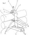
- FIG. 5 is a clamp 1 for attachment of long form, in the embodiment of cables 2, shown on a rail, in the embodiment of a C-rail 3.
- the strap clamp 1 has an approximately U-shaped body, wherein between the legs 4 of the U-shape an adjustable by means of a base 5 of the U-shape adjusting screw 6 adjustable pressure pan 7 is arranged.
- the pressure trough 7 comprises the cable 2 partially and braces this cable 2 against a resting on the rail 3 counter trough 8.
- the free leg ends of the approximately U-shaped body hook-shaped (at 9) and engage behind the angled free ends 10th the leg of the C-rail 3.
- the counter-trough 8 on its long-form material, in the embodiment of cable 2, facing away from profiling, by means of which the counter-trough 8 with the profiling of another, identical counter-trough 8 is connected or connected.
- the connection of two counter-troughs 8 to a double trough 18 is made possible in a quick and simple manner by simply telescoping the profilings, so that they can be arranged between two long-form goods to be laid parallel to one another like cables 2.
- Such counter-wells 8 are often made of plastic, such as polypropylene and are inexpensive and easy to manufacture and have a long service life.
- the profiling by parallel, at least over a portion of the length of the counter-well 8 extending longitudinal webs 8 is formed.
- the longitudinal webs 11 in the desired mounting position are approximately parallel to the long-form material, in the embodiment of cable 2, and are thus arranged approximately transversely to the C-profile rail 3.
- the webs 16 have a dovetail-like shape.
- the distance between two parallel, dovetailed shape having webs 16 is dimensioned such that in the intermediate space 17 each have a dovetail-like web 16 of another counter-well 8 can be received and maintained.
- a double trough 18 can also be formed here by simply telescoping two counter-troughs 8, wherein a secure cohesion of two counter-troughs 8 connected to a double trough 18 is made possible by the dovetail-like webs 16 which are inserted into the respective intermediate space 17 of a further counterpan.
- Holding element 13 is formed.
- the holding member 13 surrounds in the desired mounting position each have a leg 4 of the approximately U-shaped body of the clamp 1 and engages behind with a trained at the free end of the support member 13 hook-like projection 14 this leg 4.
Landscapes
- Engineering & Computer Science (AREA)
- General Engineering & Computer Science (AREA)
- Mechanical Engineering (AREA)
- Architecture (AREA)
- Civil Engineering (AREA)
- Structural Engineering (AREA)
- Supports For Pipes And Cables (AREA)
- Clamps And Clips (AREA)
Abstract
Description
- Die Erfindung betrifft eine Bügelschelle zur Befestigung von Langformgütern, wie insbesondere Kabeln, an einer Profilschiene, insbesondere einer C-Profilschiene, aufweisend einen etwa U-förmigen Körper, wobei zwischen den Schenkeln der U-Form eine mittels einer die Basis der U-Form durchgreifenden Stellschraube verstellbare Druckwanne angeordnet ist, die das Kabel teilweise umfasst und gegen eine auf der Profilschiene aufliegend angeordnete Gegenwanne verspannt, wobei die freien Schenkelenden des etwa U-förmigen Körpers hakenartig ausgebildet sind und die abgewinkelten freien Enden der Schenkel der Profilschiene hintergreifen.
- Derartige Bügelschellen sind im Stand der Technik vielfach bekannt und weit verbreitet.
- Derartige Bügelschellen dienen dazu, Langformgüter, wie insbesondere Kabel an Gebäudeteilen wie Decken oder Wänden zu verlegen und zu fixieren.
- Je nach Durchmesser des zu verlegenden Kabels sind dabei Bügelschellen und Profilschienen in verschiedenen Größen und Abmessungen bekannt. So sind beispielsweise Bügelschellen für zu verlegende und zu fixierende Kabel von etwa 10 mm Kabeldurchmesser bis hin zu mehr als 100 mm Kabeldurchmesser bekannt und weisen entsprechende Abmessungen auf.
- Bei der Verlegung derartiger Kabel mittels einer entsprechenden Bügelschelle wird in einem ersten Arbeitsgang die Profilschiene an der entsprechenden Wand oder Decke befestigt. Anschließend wird die Bügelschelle über das zu fixierende Kabel das kabelumgreifend aufgestülpt und an der Profilschiene verhakt oder eingehängt.
- Nun wird die Gegenwanne zwischen Kabel und Schiene geschoben und mittels der Spannschraube die Druckwanne gegen das durchgeführte Kabel verspannt, wodurch einerseits das Kabel und andererseits die Bügelschelle an der Profilschiene fixiert ist. In der Praxis ist es jedoch bekannt und häufig üblich, bis zu drei parallel zueinander verlaufende Langformgüter wie Kabel mittels nur einer Bügelschelle zu fixieren. Hierzu ist es im Stand der Technik bekannt, eine abweichende Form aufweisende Gegenwanne als Doppelwanne zu bevorraten und zwischen zwei aufeinanderfolgenden Langformgütern wie Kabeln bei der Montage zu positionieren. Durch die abweichende Form der Doppelwannen ist es zum einen nachteilig, dass der Monteur vor Ort eine erhöhte Anzahl an Teilen bevorraten muss und zum anderen nachteilig, dass diese zwischen zwei parallel verlaufenden Langformgütern, wie Kabeln, angeordneten Doppelwannen keine Lagefixierung zwischen den zu fixierenden Kabeln sowohl in Zug- als auch in Schubrichtung aufweisen.
- Aufgrund des eingangs genannten Standes der Technik liegt der vorliegenden Erfindung die Aufgabe zugrunde, eine Bügelschelle der eingangs genannten Art zu schaffen, bei der die Anzahl der vom Monteur vor Ort zu bevorratenden Teile verringert ist, bei der andererseits nach Positionierung zwischen zwei parallel zueinander angeordneten Langformgütern wie Kabeln eine Wegbegrenzung sowohl in Einschubrichtung des Langformgutes, wie auch in Zugrichtung des Langformgutes gegeben ist, welche dabei kostengünstig und einfach zu fertigen ist und eine hohe Lebensdauer aufweist.
- Zur Lösung der ersten Teilaufgabe schlägt die Erfindung vor, dass die Gegenwanne auf ihrer dem Langformgut, insbesondere Kabel, abgewandten Seite eine Profilierung aufweist, mittels derer die Gegenwanne mit der Profilierung einer weiteren, identischen Gegenwanne zu einer Doppelwanne verbindbar oder verbunden ist.
- Mittels einer derartigen Profilierung auf der dem Langformgut abgewandten Seite der Gegenwanne ist es auf schnelle und einfache Art und Weise ermöglicht, zwei identische Gegenwannen im Bereich ihrer Profilierung miteinander zu einer Doppelwanne zu verbinden, sodass hierdurch die parallele Anordnung von zwei aufeinanderfolgenden Langformgütern wie Kabeln innerhalb einer Bügelschelle ermöglicht ist ohne eine weitere, separate Doppelwanne zu verwenden. Der Monteur braucht lediglich vor Ort zwei entsprechende, identische Gegenwannen miteinander zur Bildung einer Doppelwanne zu verbinden, um die parallele Verlegung von zwei oder mehreren Kabeln beziehungsweise Langformgütern zu ermöglichen. Anschließend wird auf an sich bekannter Art und Weise eine einzelne Gegenwanne zwischen Kabel und Profilschiene angeordnet. Somit ist die Anzahl der zu bevorratenden Teile für den Monteur vor Ort verringert.
- Derartige Gegenwannen bestehen häufig aus Kunststoff, wie beispielsweise Polypropylen, und können im Spritzgießverfahren kostengünstig und einfach hergestellt werden und weisen dabei eine hohe Lebensdauer auf.
- Insbesondere kann dabei besonders bevorzugt vorgesehen sein, dass die Profilierung durch parallele, sich zumindest über einen Teil der Länge der Gegenwanne erstreckende Längsstege, die in der Montagesolllage etwa parallel zum Langformgut beziehungsweise Kabel verlaufend und somit quer zur Profilschiene angeordnet sind, gebildet ist.
- Die Anordnung derartiger Längsstege als Profilierung ermöglicht ein besonders schnelles und einfaches und dabei lagegenaues miteinander Verbinden zweier identischer Gegenwannen zur späteren Positionierung zwischen zwei parallel verlaufenden Langformgütern wie Kabeln. Hierzu müssen die zu einer Doppelwanne zu verbindenden Gegenwannen lediglich händisch voreinander positioniert und anschließend aufeinander zubewegt werden, wobei die linearen Stege ein seitliches Verrutschen verhindern und die lagegenaue Positionierung und anschließende Montagesolllage ermöglichen. Die linear verlaufenden Längsstege dienen dabei gleichzeitig sowohl als Positioniermittel wie auch nach Erreichen der zusammengeschobenen Gebrauchslage als Arretiermittel, wobei die linear verlaufenden Längsstege eine geringe Verklemmung gegenüber den parallel verlaufenden Längsstegen des jeweils anderen Teils ermöglichen.
- Somit erfolgt bereits durch die Längsstege ein Verbleiben der zusammengesetzten Gegenwannen in der Gebrauchslage um diese bei der Montage zwischen zwei parallelen Kabeln anzuordnen.
- Insbesondere kann besonders bevorzugt vorgesehen sein, dass die Profilierung durch parallele, sich mindestens über einen Teil der Länge oder der Breite der Gegenwanne erstreckende schwalbenschwanzartige Stege gebildet ist, wobei der Zwischenraum zwischen zwei parallelen schwalbenschwanzartigen Stegen einen Aufnahmeraum für einen schwalbenschwanzartigen Steg der weiteren, identischen Gegenwanne bildet.
- Durch die schwalbenschwanzartige Form der Stege können diese auf einfache und schnelle Art und Weise ineinander geschoben werden, wobei ein sicherer Verbleib in dieser verbundenen Lage als Doppelwanne erfolgt. Alternativ zur schwalbenschwanzartigen Form der Stege können auch andere Formen, die einen Hinterschnitt und somit Halt am jeweils anderen Stück ermöglichen, Verwendung finden.
- Auch kann dabei die Ausbildung der Stege sowohl als Längsstege, also etwa parallel zum befestigten
- Langformgut wie Kabel oder als Querstege, und somit etwa quer zur Verlaufsrichtung der Langformgüter beziehungsweise Kabel angeordnet sein.
- Diese Ausbildung von Querstegen ist dabei grundsätzlich für jede, eine Profilierung bildende Stegform möglich.
- Darüber hinaus kann besonders bevorzugt vorgesehen sein, dass die Profilierung Rastvorsprünge aufweist, wobei in der miteinander verbundenen Lage zweier Gegenwannen die Rastvorsprünge jeweils einen Wegbegrenzungsanschlag für einen an der anderen Gegenwanne ausgebildeten Rastvorsprung bilden.
- Die zusätzlich zu den Längsstegen angeordneten Rastvorsprünge stellen bei dem Zusammensetzen zweier Gegenwannen zu einer Doppelwanne jederzeit sicher, dass die zusammengesetzte Gebrauchslage erreicht und nicht überschritten wird. Dies bedeutet, dass beim Zusammenschieben zweier zu verbindender Gegenwannen die Rastvorsprünge das Erreichen der Gebrauchslage zum einen durch einen Wegbegrenzungsanschlag bilden, wodurch der Monteur sofort Rückmeldung erhält, dass die beiden zusammengesetzten Gegenwannen nun ihre Gebrauchslage erreicht haben. Somit ist ein Schieben über das Erreichen der Gebrauchslage hinaus durch diese einen Wegbegrenzungsanschlag bildenden Rastsprünge wirksam verhindert.
- Insbesondere zur Lösung der zweiten Teilaufgabe kann besonders bevorzugt vorgesehen sein, dass die Gegenwanne ein seitlich abragendes, etwa parallel zur Längsrichtung der Gegenwanne verlaufendes, Halteelement aufweist, welches einen Schenkel des etwa U- förmigen Körpers der Bügelschelle umgreift und nach Erreichen der Montagesollage diesen Schenkel mit einem am freien Ende des Halteelements ausgebildeten hakenartigen Vorsprung hintergreift, wobei der Schenkel des etwa U- förmigen Körpers der Bügelschelle in dieser Montagesolllage zwischen dem hakenartigen Vorsprung des Halteelements und dem von der Gegenwanne abragenden Bereich, der einen Übergangsbereich von der Gegenwanne zum Halteelement bildet, angeordnet ist.
- Die Ausbildung eines derartigen Halteelements mit hakenartigem Vorsprung bewirkt sowohl bei der Verwendung einer einzelnen Gegenwanne eine lagegenaue Positionierung am jeweiligen Schenkel der Bügelschelle als auch in der zusammengesetzten Lage mit einer weiteren Gegenwanne. In der zusammengesetzten Lage zweier Gegenwannen umgreift dabei jeweils ein Halteelement einer Gegenwanne einen Schenkel des etwa U-förmigen Körpers der Bügelschelle und umgreift diesen. Nach Erreichen dieser umgreifenden Lage ist ein Verschieben, das heißt Entfernen aus der Montagesolllage sowohl einer einzelnen Gegenwanne als auch einer aus zwei Gegenwannen zusammengesetzten Gegenwanne, sowohl bei auftretenden Kräften in Einschubrichtung als auch bei auftretenden Kräften in Zugrichtung, also gegen die Einschubrichtung, wirksam verhindert. Der jeweilige Schenkel des etwa U-förmigen Körpers der Bügelschelle befindet sich dabei in einem Bereich zwischen dem hakenartigen Vorsprung am freien Ende des Halteelements und dem von der Gegenwanne abragenden Bereich, der das Halteelement aufnimmt. Der Schenkel ist nach Erreichen dieser Montagesolllage zwischen diesen Bereichen fixiert, wodurch ein Verschieben sowohl in Einschubrichtung des Langformgutes, als auch in Zugrichtung des Langformgutes wirksam verhindert ist und sowohl eine einzelne Gegenwanne als auch eine zusammengesetzte Gegenwanne immer lagerichtig an der Bügelschelle positioniert ist.
- Insbesondere beim späteren Verspannen von durchgeführten Langformgütern wie Kabeln, werden häufig Zug- beziehungsweise Druckkräfte auf die Gegenwannen ausgeübt, sodass diese ihre Sollposition verlassen, was durch die erfindungsgemäße Lösung wirksam verhindert ist.
- Eine derartige erfindungsgemäße Gegenwanne kann darüber hinaus auch bei Bügelschellen anderer Art, wie beispielsweise einer Universalbügelschelle, einer Bügelschelle für Flacheisen oder einer Bügelschelle für Winkeleisen Verwendung finden, da hierbei lediglich die jeweilige Form der Schenkelenden des etwa U-förmigen Körpers der Bügelschelle abweichend ausgebildet ist, wodurch kein Einfluss auf die Funktion der Gegenwanne erfolgt. Durch die parallel zur Verlaufsrichtung der durchgeführten Langformgüter oder quer zur Verlaufsrichtung der durchgeführten Langformgüter angeordneten, eine Profilierung bildenden, Stege, ist ein schnelles und einfaches Verbinden zweier Gegenwannen zu einer Doppelwanne ermöglicht.
- Ein Ausführungsbeispiel der Erfindung ist in den Zeichnungen dargestellt und im Folgenden näher beschrieben.
- Es zeigt:
- Figur 1
- eine erfindungsgemäße Gegenwanne rückseitig schräg von oben gesehen;
- Figur 2
- desgleichen vorderseitig schräg von oben gesehen;
- Figur 3
- zwei zusammengesetzte erfindungsgemäße Gegenwannen von vorne gesehen;
- Figur 4
- desselben von schräg oben gesehen;
- Figur 5
- eine Bügelschelle mit erfindungsgemäßen Gegenwannen und zwei parallel angeordneten Kabeln an einer C-Profilschiene montiert.
- Figur 6
- ein weiteres Ausführungsbeispiel der Erfindung mit schwalbenschwanzartigen Längsstegen als Profilierung.
- In
Figur 5 ist eine Bügelschelle 1 zur Befestigung von Langformgütern, im Ausführungsbeispiel von Kabeln 2, an einer Profilschiene, im Ausführungsbeispiel an einer C-Profilschiene 3 gezeigt. Die Bügelschelle 1 weist einen etwa U-förmigen Körper auf, wobei zwischen den Schenkeln 4 der U-Form eine mittels einer die Basis 5 der U-Form durchgreifenden Stellschraube 6 verstellbare Druckwanne 7 angeordnet ist. Die Druckwanne 7 umfasst das Kabel 2 teilweise und verspannt dieses Kabel 2 gegen eine auf der Profilschiene 3 aufliegend angeordnete Gegenwanne 8. Dabei sind im Ausführungsbeispiel die freien Schenkelenden des etwa U-förmigen Körpers hakenartig (bei 9) ausgebildet und hintergreifen die abgewinkelten freien Enden 10 der Schenkel der C-Profilschiene 3. - Erfindungsgemäß weist die Gegenwanne 8 auf ihrer dem Langformgut, im Ausführungsbeispiel Kabel 2, abgewandten Seite eine Profilierung auf, mittels derer die Gegenwanne 8 mit der Profilierung einer weiteren, identischen Gegenwanne 8 verbindbar oder verbunden ist. Hierdurch ist auf schnelle und einfache Art und Weise, durch einfaches Ineinanderschieben der Profilierungen die Verbindung zweier Gegenwannen 8 zu einer Doppelwanne 18 ermöglicht, sodass diese zwischen zwei parallel zueinander zu verlegenden Langformgütern wie Kabeln 2 angeordnet werden kann. Hierdurch ist für einen Monteur vor Ort die Anzahl an mitzuführenden Teilen reduziert, da er nur eine Art Gegenwanne 8 mitführen muss und diese bei Bedarf mit einer weiteren, identischen Gegenwanne 8 zu einer Doppelwanne 18 verbindet, um diese miteinander verbundenen Teile zwischen zwei parallel zueinander verlaufenden Langformgütern anzuordnen.
- Derartige Gegenwannen 8 bestehen häufig aus Kunststoff, wie beispielsweise Polypropylen und sind kostengünstig und einfach herzustellen und weisen dabei eine hohe Lebensdauer auf.
- Wie insbesondere aus den
Figuren 1 und2 ersichtlich, ist die Profilierung durch parallele, sich zumindest über einen Teil der Länge der Gegenwanne 8 erstreckende Längsstege 8 gebildet. Dabei verlaufen die Längsstege 11 in der Montagesolllage etwa parallel zum Langformgut, im Ausführungsbeispiel Kabel 2, und sind somit etwa quer zur C-Profilschiene 3 angeordnet. - Bei dem in
Figur 6 gezeigten Ausführungsbeispiel weisen die Stege 16 eine schwalbenschwanzartige Form auf. Dabei ist der Abstand zwischen zwei parallel verlaufenden, schwalbenschwanzartige Form aufweisenden Stegen 16 derart bemessen, dass in dem Zwischenraum 17 jeweils ein schwalbenschwanzartiger Steg 16 einer weiteren Gegenwanne 8 aufgenommen und gehalten werden kann. - Somit kann auch hierbei durch einfaches Ineinanderschieben zweier Gegenwannen 8 eine Doppelwanne 18 gebildet werden, wobei durch die schwalbenschwanzartigen Stege 16, die in den jeweiligen Zwischenraum 17 einer weiteren Gegenwanne eingeführt werden, ein sicherer Zusammenhalt zweier zu einer Doppelwanne 18 verbundener Gegenwannen 8 ermöglicht ist.
- Zudem weist die Profilierung zusätzliche Rastvorsprünge 12 auf, wie insbesondere aus
Figur 1 ersichtlich, wobei in der miteinander verbundenen Lage zweier Gegenwannen 8 die Rastvorsprünge 12 jeweils einen Wegbegrenzungsanschlag für einen an der anderen Gegenwanne 8 ausgebildeten Rastvorsprung 12 bilden. Hierdurch ist es beim Verbinden, das heißt Ineinanderschieben zweier zu verbindender Gegenwannen 8 jederzeit sichergestellt, dass diese nicht über die Endlage hinaus zueinander verschoben werden können. Somit ist ein Verschieben über die Solllage hinaus durch die einen Wegbegrenzungsanschlag bildenden Rastvorsprünge 12 wirksam verhindert und ein genauer Sitz zweier miteinander verbundener Gegenwannen 8 sichergestellt. - Um einen lagegenauen Sitz sowohl einer einzelnen Gegenwanne 8 als auch zweier miteinander verbundener Gegenwannen 8 an dem einen Schenkel 4 beziehungsweise an beiden Schenkeln 4 der Bügelschelle 1 sicherzustellen, ist an jeder Gegenwanne 8 jeweils ein seitlich abragendes, etwa parallel zur Längsrichtung der Gegenwanne 8 verlaufendes, Halteelement 13 ausgebildet. Das Halteelement 13 umgreift in der Montagesolllage jeweils einen Schenkel 4 des etwa U-förmigen Körpers der Bügelschelle 1 und hintergreift mit einem am freien Ende des Halteelements 13 ausgebildeten hakenartigen Vorsprung 14 diesen Schenkel 4. In dieser Lage sind die kurzen Seitenkanten des Schenkels 4 des etwa U-förmigen Körpers der Bügelschelle 1 zwischen dem hakenartigen Vorsprung 14 des Halteelements 13 und dem von der Gegenwanne 8 abragenden Bereich 15, der einen Übergangsbereich von der Gegenwanne 8 zum Halteelement 13 bildet, angeordnet und die jeweilige Gegenwanne 8 somit sowohl gegen ein Verschieben in Einschubrichtung des Langformgutes, als auch gegen ein Verschieben in Zugrichtung des Langformgutes gesichert. Somit ist insbesondere beim späteren Ausüben von Zug- oder Druckkräften sowohl in Einschubrichtung als auch in Zugrichtung des Langformgutes ein Verbleib in dieser Montagesolllage sichergestellt.
- Die Erfindung ist nicht auf das Ausführungsbeispiel beschränkt, sondern im Rahmen der Offenbarung vielfach variabel.
- Alle in der Beschreibung und/oder Zeichnung offenbarten Einzel- und Kombinationsmerkmale werden als erfindungswesentlich angesehen.
-
- 1)
- Bügelschelle
- 2)
- Kabel
- 3)
- C-Profilschiene
- 4)
- Schenkel
- 5)
- Basis
- 6)
- Stellschraube
- 7)
- Druckwanne
- 8)
- Gegenwanne
- 9)
- Hakenartige Enden (von 4)
- 10)
- Abgewinkelte freie Enden (von 3)
- 11)
- Längsstege
- 12)
- Rastvorsprünge
- 13)
- Halteelement
- 14)
- hakenartiger Vorsprung (an 13)
- 15)
- von 8 abragender Bereich
- 16)
- schwalbenschwanzartige Stege
- 17)
- Zwischenraum
- 18)
- Doppelwanne
Claims (5)
- Bügelschelle (1) zur Befestigung von Langformgütern, wie insbesondere Kabeln (2), an einer Profilschiene, insbesondere einer C-Profilschiene (3), aufweisend einen etwa U-förmigen Körper, wobei zwischen den Schenkeln (4) der U- Form eine mittels einer die Basis (5) der U-Form durchgreifenden Stellschraube (6) verstellbare Druckwanne (7) angeordnet ist, die das Kabel (2) teilweise umfasst und gegen eine auf der Profilschiene (3) aufliegend angeordnete Gegenwanne (8) verspannt, wobei die freien Schenkelenden des etwa U- förmigen Körpers hakenartig (bei 9) ausgebildet sind und die abgewinkelten freien Enden (10) der Schenkel der Profilschiene (3) hintergreifen, dadurch gekennzeichnet, dass die Gegenwanne (8) auf ihrer dem Langformgut, insbesondere Kabel (2) abgewandten Seite eine Profilierung aufweist, mittels derer die Gegenwanne (8) mit der Profilierung einer weiteren, identischen Gegenwanne (8) zu einer Doppelwanne (18) verbindbar oder verbunden ist.
- Bügelschelle (1) nach Anspruch 1, dadurch gekennzeichnet, dass die Profilierung durch parallele, sich zumindest über einen Teil der Länge der Gegenwanne (8) erstreckende Längsstege (11), die in der Montagesolllage etwa parallel zum Langformgut beziehungsweise Kabel (2) verlaufend und somit quer zur Profilschiene (3) angeordnet sind, gebildet ist.
- Bügelschelle (1) nach Anspruch 1, dadurch gekennzeichnet, dass die Profilierung durch parallele, sich mindestens über einen Teil der Länge oder der Breite der Gegenwanne erstreckende schwalbenschwanzartige Stege gebildet ist, wobei der Zwischenraum zwischen zwei parallelen schwalbenschwanzartigen Stegen einen Aufnahmeraum für einen schwalbenschwanzartigen Steg der weiteren, identischen Gegenwanne bildet.
- Bügelschelle (1) nach einem der Ansprüche 1 bis 3, dadurch gekennzeichnet, dass die Profilierung Rastvorsprünge (12) aufweist, wobei in der miteinander verbundenen Lage zweier Gegenwannen (8) die Rastvorsprünge (12) jeweils einen Wegbegrenzungsanschlag für einen an der anderen Gegenwanne (8) ausgebildeten Rastvorsprung (12) bilden.
- Bügelschelle (1) nach einem der Ansprüche 1 bis 4, dadurch gekennzeichnet, dass die Gegenwanne (8) ein seitlich abragendes, etwa parallel zur Längsrichtung der Gegenwanne (8) verlaufendes, Halteelement (13) aufweist, welches einen Schenkel (4) des etwa U- förmigen Körpers der Bügelschelle (1) umgreift und nach Erreichen der Montagesollage diesen Schenkel (4) mit einem am freien Ende des Halteelements (13) ausgebildeten hakenartigen Vorsprung (14) hintergreift, wobei der Schenkel (4) des etwa U- förmigen Körpers der Bügelschelle (1) in dieser Montagesolllage zwischen dem hakenartigen Vorsprung (14) des Halteelements (13) und dem von der Gegenwanne (8) abragenden Bereich (15), der einen Übergangsbereich von der Gegenwanne (8) zum Halteelement (13) bildet, angeordnet ist.
Priority Applications (1)
| Application Number | Priority Date | Filing Date | Title |
|---|---|---|---|
| PL18189099T PL3457012T3 (pl) | 2017-09-18 | 2018-08-15 | Obejma |
Applications Claiming Priority (1)
| Application Number | Priority Date | Filing Date | Title |
|---|---|---|---|
| DE202017105636.8U DE202017105636U1 (de) | 2017-09-18 | 2017-09-18 | Bügelschelle |
Publications (2)
| Publication Number | Publication Date |
|---|---|
| EP3457012A1 true EP3457012A1 (de) | 2019-03-20 |
| EP3457012B1 EP3457012B1 (de) | 2020-02-26 |
Family
ID=60119127
Family Applications (1)
| Application Number | Title | Priority Date | Filing Date |
|---|---|---|---|
| EP18189099.7A Active EP3457012B1 (de) | 2017-09-18 | 2018-08-15 | Bügelschelle |
Country Status (5)
| Country | Link |
|---|---|
| EP (1) | EP3457012B1 (de) |
| DE (1) | DE202017105636U1 (de) |
| ES (1) | ES2791423T3 (de) |
| HU (1) | HUE048825T2 (de) |
| PL (1) | PL3457012T3 (de) |
Cited By (1)
| Publication number | Priority date | Publication date | Assignee | Title |
|---|---|---|---|---|
| EP3933115A4 (de) * | 2019-05-08 | 2022-12-21 | Kobelco Construction Machinery Co., Ltd. | Hydraulische rohrklemmvorrichtung für baumaschine |
Families Citing this family (1)
| Publication number | Priority date | Publication date | Assignee | Title |
|---|---|---|---|---|
| WO2020025935A1 (en) * | 2018-08-03 | 2020-02-06 | Izzifix Limited | A connection system for connecting a conduit to a wall |
Citations (5)
| Publication number | Priority date | Publication date | Assignee | Title |
|---|---|---|---|---|
| DE1236620B (de) * | 1965-07-13 | 1967-03-16 | Niedax Gmbh | Wanne fuer Kabelschellen |
| DE8504051U1 (de) * | 1985-02-14 | 1985-05-15 | Unima Maschinenbau Gmbh, 6603 Sulzbach | Schelle für Rohre, Schläuche od. dgl. |
| DE3824197A1 (de) * | 1988-07-16 | 1990-01-18 | Theodor Stratmann | Rohrschelle |
| DE102012024122A1 (de) * | 2012-12-11 | 2014-06-12 | Flexa Gmbh & Co. Produktion Und Vertrieb Kg | Haltesystem zum Halten und Positionieren von langen Gegenständen, wie Schläuchen, Rohren, Kabeln, und dergleichen |
| DE202015007620U1 (de) * | 2015-11-04 | 2015-12-15 | Fkb Gmbh | Führungs- oder Haltevorrichtung zur Aufnahme von Rohren, Kabeln oder Schläuchen |
-
2017
- 2017-09-18 DE DE202017105636.8U patent/DE202017105636U1/de active Active
-
2018
- 2018-08-15 PL PL18189099T patent/PL3457012T3/pl unknown
- 2018-08-15 ES ES18189099T patent/ES2791423T3/es active Active
- 2018-08-15 HU HUE18189099A patent/HUE048825T2/hu unknown
- 2018-08-15 EP EP18189099.7A patent/EP3457012B1/de active Active
Patent Citations (5)
| Publication number | Priority date | Publication date | Assignee | Title |
|---|---|---|---|---|
| DE1236620B (de) * | 1965-07-13 | 1967-03-16 | Niedax Gmbh | Wanne fuer Kabelschellen |
| DE8504051U1 (de) * | 1985-02-14 | 1985-05-15 | Unima Maschinenbau Gmbh, 6603 Sulzbach | Schelle für Rohre, Schläuche od. dgl. |
| DE3824197A1 (de) * | 1988-07-16 | 1990-01-18 | Theodor Stratmann | Rohrschelle |
| DE102012024122A1 (de) * | 2012-12-11 | 2014-06-12 | Flexa Gmbh & Co. Produktion Und Vertrieb Kg | Haltesystem zum Halten und Positionieren von langen Gegenständen, wie Schläuchen, Rohren, Kabeln, und dergleichen |
| DE202015007620U1 (de) * | 2015-11-04 | 2015-12-15 | Fkb Gmbh | Führungs- oder Haltevorrichtung zur Aufnahme von Rohren, Kabeln oder Schläuchen |
Cited By (1)
| Publication number | Priority date | Publication date | Assignee | Title |
|---|---|---|---|---|
| EP3933115A4 (de) * | 2019-05-08 | 2022-12-21 | Kobelco Construction Machinery Co., Ltd. | Hydraulische rohrklemmvorrichtung für baumaschine |
Also Published As
| Publication number | Publication date |
|---|---|
| HUE048825T2 (hu) | 2020-08-28 |
| PL3457012T3 (pl) | 2020-07-27 |
| DE202017105636U1 (de) | 2017-10-02 |
| EP3457012B1 (de) | 2020-02-26 |
| ES2791423T3 (es) | 2020-11-04 |
Similar Documents
| Publication | Publication Date | Title |
|---|---|---|
| DE19815047A1 (de) | Anordnung zur schraubenlosen Verbindung von Gitterkabelbahnen | |
| EP0355081A2 (de) | Kabelverlegungskanal | |
| EP2944737B1 (de) | Spannvorrichtung zum verbinden von profilschienen | |
| EP3457012B1 (de) | Bügelschelle | |
| DE4422885C2 (de) | Montageelement | |
| EP2869417B1 (de) | Vorrichtung zum Verbinden von Kabelbahnabschnitten und Kabelbahn | |
| DE102013225173A1 (de) | Montageprofil für plattenförmige Module | |
| DE2256045A1 (de) | Gelaender | |
| EP0555187A1 (de) | Befestigungsschiene, insbesondere für Kabel und Elektrorohre | |
| DE202006007455U1 (de) | Zaunelement | |
| EP0961039B1 (de) | Verbindungsvorrichtung | |
| EP1243203B1 (de) | Schienenmontagesystem | |
| AT509393B1 (de) | Wandstütze | |
| EP3234446A1 (de) | Verbindungseinrichtung | |
| DE202004009557U1 (de) | System zur Aufhängung von Rohren, Leitungen o.dgl. an einer Decke | |
| EP1491698B1 (de) | Aus Stäben gebildete Verkleidung von Decken, Wänden oder dergleichen Bauwerkteilen | |
| DE202005001921U1 (de) | Schienenaggregat, vorgefertigte Einheit zur Herstellung eines Schienenaggregates und Verbindungselement für ein Schienenaggregat | |
| EP4130409B1 (de) | Befestigungssystem für verkleidungselemente | |
| DE102013006551A1 (de) | Montagesystem für die Anordnung von beispielsweise elektrischen Einrichtungen insbesondere in Schaltschränken | |
| DE102005056129B4 (de) | Eckverbindungsanordnung mit Verzahnung | |
| EP1801305A2 (de) | Träger für Installationen im Bereich der Haustechnik und der Industrie | |
| CH658092A5 (de) | Bausatz zum erstellen einer abhaengbaren rasterdecke. | |
| EP3146123B1 (de) | Fugenabdeckvorrichtung | |
| EP2639909A1 (de) | Kabelkanalsystem | |
| DE202023105230U1 (de) | Rohrmontage-Hilfsvorrichtung mit einem Abstandshalter |
Legal Events
| Date | Code | Title | Description |
|---|---|---|---|
| PUAI | Public reference made under article 153(3) epc to a published international application that has entered the european phase |
Free format text: ORIGINAL CODE: 0009012 |
|
| STAA | Information on the status of an ep patent application or granted ep patent |
Free format text: STATUS: THE APPLICATION HAS BEEN PUBLISHED |
|
| AK | Designated contracting states |
Kind code of ref document: A1 Designated state(s): AL AT BE BG CH CY CZ DE DK EE ES FI FR GB GR HR HU IE IS IT LI LT LU LV MC MK MT NL NO PL PT RO RS SE SI SK SM TR |
|
| AX | Request for extension of the european patent |
Extension state: BA ME |
|
| STAA | Information on the status of an ep patent application or granted ep patent |
Free format text: STATUS: REQUEST FOR EXAMINATION WAS MADE |
|
| 17P | Request for examination filed |
Effective date: 20190819 |
|
| RBV | Designated contracting states (corrected) |
Designated state(s): AL AT BE BG CH CY CZ DE DK EE ES FI FR GB GR HR HU IE IS IT LI LT LU LV MC MK MT NL NO PL PT RO RS SE SI SK SM TR |
|
| GRAP | Despatch of communication of intention to grant a patent |
Free format text: ORIGINAL CODE: EPIDOSNIGR1 |
|
| STAA | Information on the status of an ep patent application or granted ep patent |
Free format text: STATUS: GRANT OF PATENT IS INTENDED |
|
| INTG | Intention to grant announced |
Effective date: 20191120 |
|
| GRAS | Grant fee paid |
Free format text: ORIGINAL CODE: EPIDOSNIGR3 |
|
| GRAA | (expected) grant |
Free format text: ORIGINAL CODE: 0009210 |
|
| STAA | Information on the status of an ep patent application or granted ep patent |
Free format text: STATUS: THE PATENT HAS BEEN GRANTED |
|
| REG | Reference to a national code |
Ref country code: DE Ref legal event code: R082 Ref document number: 502018000832 Country of ref document: DE Representative=s name: PATENTANWAELTE KOECHLING, DOERING PARTG MBB, DE |
|
| AK | Designated contracting states |
Kind code of ref document: B1 Designated state(s): AL AT BE BG CH CY CZ DE DK EE ES FI FR GB GR HR HU IE IS IT LI LT LU LV MC MK MT NL NO PL PT RO RS SE SI SK SM TR |
|
| REG | Reference to a national code |
Ref country code: GB Ref legal event code: FG4D Free format text: NOT ENGLISH |
|
| REG | Reference to a national code |
Ref country code: CH Ref legal event code: EP |
|
| REG | Reference to a national code |
Ref country code: DE Ref legal event code: R096 Ref document number: 502018000832 Country of ref document: DE |
|
| REG | Reference to a national code |
Ref country code: AT Ref legal event code: REF Ref document number: 1238044 Country of ref document: AT Kind code of ref document: T Effective date: 20200315 |
|
| REG | Reference to a national code |
Ref country code: IE Ref legal event code: FG4D Free format text: LANGUAGE OF EP DOCUMENT: GERMAN |
|
| REG | Reference to a national code |
Ref country code: NL Ref legal event code: FP |
|
| PG25 | Lapsed in a contracting state [announced via postgrant information from national office to epo] |
Ref country code: RS Free format text: LAPSE BECAUSE OF FAILURE TO SUBMIT A TRANSLATION OF THE DESCRIPTION OR TO PAY THE FEE WITHIN THE PRESCRIBED TIME-LIMIT Effective date: 20200226 Ref country code: FI Free format text: LAPSE BECAUSE OF FAILURE TO SUBMIT A TRANSLATION OF THE DESCRIPTION OR TO PAY THE FEE WITHIN THE PRESCRIBED TIME-LIMIT Effective date: 20200226 Ref country code: NO Free format text: LAPSE BECAUSE OF FAILURE TO SUBMIT A TRANSLATION OF THE DESCRIPTION OR TO PAY THE FEE WITHIN THE PRESCRIBED TIME-LIMIT Effective date: 20200526 |
|
| REG | Reference to a national code |
Ref country code: LT Ref legal event code: MG4D |
|
| REG | Reference to a national code |
Ref country code: HU Ref legal event code: AG4A Ref document number: E048825 Country of ref document: HU |
|
| PG25 | Lapsed in a contracting state [announced via postgrant information from national office to epo] |
Ref country code: HR Free format text: LAPSE BECAUSE OF FAILURE TO SUBMIT A TRANSLATION OF THE DESCRIPTION OR TO PAY THE FEE WITHIN THE PRESCRIBED TIME-LIMIT Effective date: 20200226 Ref country code: SE Free format text: LAPSE BECAUSE OF FAILURE TO SUBMIT A TRANSLATION OF THE DESCRIPTION OR TO PAY THE FEE WITHIN THE PRESCRIBED TIME-LIMIT Effective date: 20200226 Ref country code: LV Free format text: LAPSE BECAUSE OF FAILURE TO SUBMIT A TRANSLATION OF THE DESCRIPTION OR TO PAY THE FEE WITHIN THE PRESCRIBED TIME-LIMIT Effective date: 20200226 Ref country code: IS Free format text: LAPSE BECAUSE OF FAILURE TO SUBMIT A TRANSLATION OF THE DESCRIPTION OR TO PAY THE FEE WITHIN THE PRESCRIBED TIME-LIMIT Effective date: 20200626 Ref country code: GR Free format text: LAPSE BECAUSE OF FAILURE TO SUBMIT A TRANSLATION OF THE DESCRIPTION OR TO PAY THE FEE WITHIN THE PRESCRIBED TIME-LIMIT Effective date: 20200527 Ref country code: BG Free format text: LAPSE BECAUSE OF FAILURE TO SUBMIT A TRANSLATION OF THE DESCRIPTION OR TO PAY THE FEE WITHIN THE PRESCRIBED TIME-LIMIT Effective date: 20200526 |
|
| PG25 | Lapsed in a contracting state [announced via postgrant information from national office to epo] |
Ref country code: RO Free format text: LAPSE BECAUSE OF FAILURE TO SUBMIT A TRANSLATION OF THE DESCRIPTION OR TO PAY THE FEE WITHIN THE PRESCRIBED TIME-LIMIT Effective date: 20200226 Ref country code: LT Free format text: LAPSE BECAUSE OF FAILURE TO SUBMIT A TRANSLATION OF THE DESCRIPTION OR TO PAY THE FEE WITHIN THE PRESCRIBED TIME-LIMIT Effective date: 20200226 Ref country code: CZ Free format text: LAPSE BECAUSE OF FAILURE TO SUBMIT A TRANSLATION OF THE DESCRIPTION OR TO PAY THE FEE WITHIN THE PRESCRIBED TIME-LIMIT Effective date: 20200226 Ref country code: EE Free format text: LAPSE BECAUSE OF FAILURE TO SUBMIT A TRANSLATION OF THE DESCRIPTION OR TO PAY THE FEE WITHIN THE PRESCRIBED TIME-LIMIT Effective date: 20200226 Ref country code: SM Free format text: LAPSE BECAUSE OF FAILURE TO SUBMIT A TRANSLATION OF THE DESCRIPTION OR TO PAY THE FEE WITHIN THE PRESCRIBED TIME-LIMIT Effective date: 20200226 Ref country code: SK Free format text: LAPSE BECAUSE OF FAILURE TO SUBMIT A TRANSLATION OF THE DESCRIPTION OR TO PAY THE FEE WITHIN THE PRESCRIBED TIME-LIMIT Effective date: 20200226 Ref country code: DK Free format text: LAPSE BECAUSE OF FAILURE TO SUBMIT A TRANSLATION OF THE DESCRIPTION OR TO PAY THE FEE WITHIN THE PRESCRIBED TIME-LIMIT Effective date: 20200226 Ref country code: PT Free format text: LAPSE BECAUSE OF FAILURE TO SUBMIT A TRANSLATION OF THE DESCRIPTION OR TO PAY THE FEE WITHIN THE PRESCRIBED TIME-LIMIT Effective date: 20200719 |
|
| REG | Reference to a national code |
Ref country code: ES Ref legal event code: FG2A Ref document number: 2791423 Country of ref document: ES Kind code of ref document: T3 Effective date: 20201104 |
|
| REG | Reference to a national code |
Ref country code: DE Ref legal event code: R097 Ref document number: 502018000832 Country of ref document: DE |
|
| PLBE | No opposition filed within time limit |
Free format text: ORIGINAL CODE: 0009261 |
|
| STAA | Information on the status of an ep patent application or granted ep patent |
Free format text: STATUS: NO OPPOSITION FILED WITHIN TIME LIMIT |
|
| PG25 | Lapsed in a contracting state [announced via postgrant information from national office to epo] |
Ref country code: IT Free format text: LAPSE BECAUSE OF FAILURE TO SUBMIT A TRANSLATION OF THE DESCRIPTION OR TO PAY THE FEE WITHIN THE PRESCRIBED TIME-LIMIT Effective date: 20200226 |
|
| 26N | No opposition filed |
Effective date: 20201127 |
|
| PG25 | Lapsed in a contracting state [announced via postgrant information from national office to epo] |
Ref country code: SI Free format text: LAPSE BECAUSE OF FAILURE TO SUBMIT A TRANSLATION OF THE DESCRIPTION OR TO PAY THE FEE WITHIN THE PRESCRIBED TIME-LIMIT Effective date: 20200226 |
|
| PG25 | Lapsed in a contracting state [announced via postgrant information from national office to epo] |
Ref country code: MC Free format text: LAPSE BECAUSE OF FAILURE TO SUBMIT A TRANSLATION OF THE DESCRIPTION OR TO PAY THE FEE WITHIN THE PRESCRIBED TIME-LIMIT Effective date: 20200226 |
|
| PG25 | Lapsed in a contracting state [announced via postgrant information from national office to epo] |
Ref country code: LU Free format text: LAPSE BECAUSE OF NON-PAYMENT OF DUE FEES Effective date: 20200815 |
|
| PG25 | Lapsed in a contracting state [announced via postgrant information from national office to epo] |
Ref country code: IE Free format text: LAPSE BECAUSE OF NON-PAYMENT OF DUE FEES Effective date: 20200815 |
|
| REG | Reference to a national code |
Ref country code: CH Ref legal event code: PL |
|
| PG25 | Lapsed in a contracting state [announced via postgrant information from national office to epo] |
Ref country code: LI Free format text: LAPSE BECAUSE OF NON-PAYMENT OF DUE FEES Effective date: 20210831 Ref country code: CH Free format text: LAPSE BECAUSE OF NON-PAYMENT OF DUE FEES Effective date: 20210831 |
|
| PG25 | Lapsed in a contracting state [announced via postgrant information from national office to epo] |
Ref country code: TR Free format text: LAPSE BECAUSE OF FAILURE TO SUBMIT A TRANSLATION OF THE DESCRIPTION OR TO PAY THE FEE WITHIN THE PRESCRIBED TIME-LIMIT Effective date: 20200226 Ref country code: MT Free format text: LAPSE BECAUSE OF FAILURE TO SUBMIT A TRANSLATION OF THE DESCRIPTION OR TO PAY THE FEE WITHIN THE PRESCRIBED TIME-LIMIT Effective date: 20200226 Ref country code: CY Free format text: LAPSE BECAUSE OF FAILURE TO SUBMIT A TRANSLATION OF THE DESCRIPTION OR TO PAY THE FEE WITHIN THE PRESCRIBED TIME-LIMIT Effective date: 20200226 |
|
| PG25 | Lapsed in a contracting state [announced via postgrant information from national office to epo] |
Ref country code: MK Free format text: LAPSE BECAUSE OF FAILURE TO SUBMIT A TRANSLATION OF THE DESCRIPTION OR TO PAY THE FEE WITHIN THE PRESCRIBED TIME-LIMIT Effective date: 20200226 Ref country code: AL Free format text: LAPSE BECAUSE OF FAILURE TO SUBMIT A TRANSLATION OF THE DESCRIPTION OR TO PAY THE FEE WITHIN THE PRESCRIBED TIME-LIMIT Effective date: 20200226 |
|
| GBPC | Gb: european patent ceased through non-payment of renewal fee |
Effective date: 20220815 |
|
| P01 | Opt-out of the competence of the unified patent court (upc) registered |
Effective date: 20230509 |
|
| PGFP | Annual fee paid to national office [announced via postgrant information from national office to epo] |
Ref country code: NL Payment date: 20230823 Year of fee payment: 6 |
|
| PG25 | Lapsed in a contracting state [announced via postgrant information from national office to epo] |
Ref country code: GB Free format text: LAPSE BECAUSE OF NON-PAYMENT OF DUE FEES Effective date: 20220815 |
|
| PGFP | Annual fee paid to national office [announced via postgrant information from national office to epo] |
Ref country code: ES Payment date: 20230918 Year of fee payment: 6 Ref country code: AT Payment date: 20230818 Year of fee payment: 6 |
|
| PGFP | Annual fee paid to national office [announced via postgrant information from national office to epo] |
Ref country code: PL Payment date: 20230807 Year of fee payment: 6 Ref country code: HU Payment date: 20230823 Year of fee payment: 6 Ref country code: FR Payment date: 20230822 Year of fee payment: 6 Ref country code: BE Payment date: 20230822 Year of fee payment: 6 |
|
| PGFP | Annual fee paid to national office [announced via postgrant information from national office to epo] |
Ref country code: DE Payment date: 20231030 Year of fee payment: 6 |