EP3455535B1 - Verbinder mit lösung durch ziehen an einem ring - Google Patents
Verbinder mit lösung durch ziehen an einem ring Download PDFInfo
- Publication number
- EP3455535B1 EP3455535B1 EP17725299.6A EP17725299A EP3455535B1 EP 3455535 B1 EP3455535 B1 EP 3455535B1 EP 17725299 A EP17725299 A EP 17725299A EP 3455535 B1 EP3455535 B1 EP 3455535B1
- Authority
- EP
- European Patent Office
- Prior art keywords
- ring
- endpiece
- female
- orifice
- male
- Prior art date
- Legal status (The legal status is an assumption and is not a legal conclusion. Google has not performed a legal analysis and makes no representation as to the accuracy of the status listed.)
- Active
Links
- 238000003780 insertion Methods 0.000 claims description 12
- 230000037431 insertion Effects 0.000 claims description 12
- 230000000694 effects Effects 0.000 claims description 5
- 230000002093 peripheral effect Effects 0.000 claims description 3
- 239000012779 reinforcing material Substances 0.000 claims description 2
- 230000008878 coupling Effects 0.000 claims 7
- 238000010168 coupling process Methods 0.000 claims 7
- 238000005859 coupling reaction Methods 0.000 claims 7
- 239000000463 material Substances 0.000 description 5
- 240000000966 Allium tricoccum Species 0.000 description 3
- 230000000903 blocking effect Effects 0.000 description 3
- 239000012530 fluid Substances 0.000 description 3
- 238000010146 3D printing Methods 0.000 description 1
- 238000004378 air conditioning Methods 0.000 description 1
- 239000000428 dust Substances 0.000 description 1
- 239000000446 fuel Substances 0.000 description 1
- 230000008595 infiltration Effects 0.000 description 1
- 238000001764 infiltration Methods 0.000 description 1
- 238000001746 injection moulding Methods 0.000 description 1
- 210000001503 joint Anatomy 0.000 description 1
- 238000004519 manufacturing process Methods 0.000 description 1
- 238000012986 modification Methods 0.000 description 1
- 230000004048 modification Effects 0.000 description 1
- 125000006850 spacer group Chemical class 0.000 description 1
Images

Classifications
-
- F—MECHANICAL ENGINEERING; LIGHTING; HEATING; WEAPONS; BLASTING
- F16—ENGINEERING ELEMENTS AND UNITS; GENERAL MEASURES FOR PRODUCING AND MAINTAINING EFFECTIVE FUNCTIONING OF MACHINES OR INSTALLATIONS; THERMAL INSULATION IN GENERAL
- F16L—PIPES; JOINTS OR FITTINGS FOR PIPES; SUPPORTS FOR PIPES, CABLES OR PROTECTIVE TUBING; MEANS FOR THERMAL INSULATION IN GENERAL
- F16L37/00—Couplings of the quick-acting type
- F16L37/08—Couplings of the quick-acting type in which the connection between abutting or axially overlapping ends is maintained by locking members
- F16L37/084—Couplings of the quick-acting type in which the connection between abutting or axially overlapping ends is maintained by locking members combined with automatic locking
- F16L37/098—Couplings of the quick-acting type in which the connection between abutting or axially overlapping ends is maintained by locking members combined with automatic locking by means of flexible hooks
- F16L37/0982—Couplings of the quick-acting type in which the connection between abutting or axially overlapping ends is maintained by locking members combined with automatic locking by means of flexible hooks with a separate member for releasing the coupling
-
- F—MECHANICAL ENGINEERING; LIGHTING; HEATING; WEAPONS; BLASTING
- F16—ENGINEERING ELEMENTS AND UNITS; GENERAL MEASURES FOR PRODUCING AND MAINTAINING EFFECTIVE FUNCTIONING OF MACHINES OR INSTALLATIONS; THERMAL INSULATION IN GENERAL
- F16L—PIPES; JOINTS OR FITTINGS FOR PIPES; SUPPORTS FOR PIPES, CABLES OR PROTECTIVE TUBING; MEANS FOR THERMAL INSULATION IN GENERAL
- F16L37/00—Couplings of the quick-acting type
- F16L37/08—Couplings of the quick-acting type in which the connection between abutting or axially overlapping ends is maintained by locking members
- F16L37/084—Couplings of the quick-acting type in which the connection between abutting or axially overlapping ends is maintained by locking members combined with automatic locking
- F16L37/098—Couplings of the quick-acting type in which the connection between abutting or axially overlapping ends is maintained by locking members combined with automatic locking by means of flexible hooks
- F16L37/0985—Couplings of the quick-acting type in which the connection between abutting or axially overlapping ends is maintained by locking members combined with automatic locking by means of flexible hooks the flexible hook extending radially inwardly from an outer part and engaging a bead, recess or the like on an inner part
Definitions
- the present invention relates to the field of tubular fittings in the automotive industry for connecting two fluid transport pipes and in particular for the connection of the fuel injector, filter, radiator or any other suitable equipment and / or in any other similar technical field.
- the invention relates to a tubular connector comprising a female end fitting having a hollow tubular body which extends in an axial direction and forming an axial opening in which a male end fitting provided with a flange is intended to be inserted axially, the hollow body of the female end piece comprising a notched locking member extending axially along the hollow body and which is designed to be elastically deformed radially by mechanical interference with the flange when the male end piece is inserted into the orifice of the female end-piece and to lock on the back of the collar when the male end-piece is fully inserted into the orifice of the female end-piece.
- a locking ring for connecting two male and female ends is mounted around the body of the female end and is suitable for reversibly locking the notches of the female end against a flange of the male end.
- the notches of the female endpiece are arranged on the free end of flexible fingers, the fingers also passing axially through the ring through openings arranged on the circumference of the ring.
- the ring includes a retaining lug for clinging to the collar of the male end piece.
- connection and disconnection of the two end pieces is each done by means of several manual steps which can be laborious for operators and extend the assembly or disassembly time.
- the document EP1561064 also relates to a rapid tubular connection with a female end fitting having a hollow body defining an orifice in which a male end fitting is inserted axially.
- a female end fitting having a hollow body defining an orifice in which a male end fitting is inserted axially.
- the branches are each connected to the body at a tipping point by a hinge in the form of a spacer. To engage the collar of the male end, the notches must move apart by pressing on the other end of the branches.
- the hinge has a fine thickness.
- the object of the invention is therefore to overcome the drawbacks indicated above.
- connection tubular comprising a female end fitting having a tubular hollow body which extends in an axial direction and forming an axial opening in which a male end fitting provided with a flange is intended to be inserted axially
- the hollow body of the female end fitting comprising a notched locking member extending axially along the hollow body and which is designed to be elastically deformed radially by mechanical interference with the flange during the insertion of the male end piece into the orifice of the female end piece and lock on the back of the collar when the male end piece is fully inserted into the orifice of the female end piece, characterized in that it further comprises a ring mounted slidingly coaxially with the orifice around the female end piece and which forms an oblique ramp relative to the axial direction and inclined radially towards the outside of the hollow body to elastically deform radially by lever effect the org locking latch when the ring undergoes axial traction in the direction of insertion of the male end piece into the female
- the basic idea of the invention is to be able to quickly and easily connect and disconnect two male and female ends with an easy-to-use tubular connection, composed of two main parts.
- the male end piece is automatically connected to the fitting by simple snap-fitting by axial insertion into the orifice of the female end piece.
- the male end simply disconnects from the fitting, pulling the fitting while pulling axially on a sliding ring surrounding the female end.
- the tubular connection can be easily assembled, the ring sliding in a controlled manner along the female end piece.
- the tubular connector according to the invention is compact, and with such a structure the risks of deformation which can be generated by high temperatures and / or pressure are reduced.
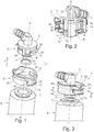
- the figure 1 presents an exploded view of different parts of a tubular connector 1 according to a first embodiment of the invention.
- the tubular connector 1 here comprises a tubular female connection end piece (female end piece) 2 bent comprising a main hollow body 3 of tubular shape which extends in an axial direction A and which has an axial orifice 4.
- the figure 1 shows a ring 5 nestable coaxially to the orifice 4 around the body 3 (according to arrow F) and the figure 2 shows the ring 5 fitted onto the body 3 of the female end piece 2 of the tubular connector 1.
- the figure 1 shows a tubular male connection end piece (male end piece) 6 which is intended to be inserted axially in the orifice 4 of the female end piece 2.
- the male end piece 6 is here in the form of a base of elongated cylindrical shape and has at its free end a radial connection stop formed by a flange 7, the diameter of the flange 7 being slightly less than that of the inside diameter of the orifice 4.
- a conduit 8 through which a fluid can flow.
- the external diameter of the conduit 8 is adjusted relative to the internal diameter of the flange 7, so that during the axial insertion of the male end piece 6 into the body 3 of the female end piece 2, the flange 7 is housed here in the orifice 4 between the body 3 of the female end piece 2 and the conduit 8.
- the seal between the two female 2 and male 6 ends can be ensured in part by a seal 9 which is housed in an annular external groove 10 of the conduit 8 as visible on the figure 2 .
- the female element 2 has at least one locking member in the form of a flexible notched finger 11 which extends in the axial direction A and which is designed to deform elastically radially outwards from the body 3 of the female end piece 2 under the effect of mechanical interference with the flange 7 when the male end piece 6 is inserted into the orifice 4 of the female end piece 2.
- the tubular body 3 may comprise several locking members 11 distributed over the circumference of the body 3.
- the tubular body 3 has two fingers 11 notched diametrically opposite with respect to the orifice 4 which are each delimited by two axial slots in the body 3 which go to the edge of the orifice 4.
- Each notched finger 11 has a free end forming an inner rib 12 inclined radially, clearly visible on the figure 2 .
- the front face of the flange 7 (in the direction of insertion of the male end piece 6 into the body 3) s press on this rib 12 to spread the finger 11 radially and allow the flange 7 to pass through the hollow body 3.
- the rib 12 also has a harpoon notch 13 which, in known manner, after the elastic tightening of the finger 11, comes into contact on the dorsal face of the flange 7 so as to axially lock in a fully inserted position and connecting the male connector 6 in the orifice 4 of the female connector 2 of the tubular connector 1.
- each notched finger 11 has at least one lateral shoulder 14 which projects radially with respect to the external circumference of the hollow body 3.
- two lateral shoulders 14 are shown and they are connected by material so as to form a lateral rib 14 'which projects radially outward from the body 3.
- Each shoulder 14 is intended to cooperate with a ramp 18 present on the ring 5 which will be described later.
- the hollow body 3 can also comprise at least one flexible clip 15 designed to deform elastically radially towards the inside of the body 3 by mechanical interference with the ring 5 when the latter is fitted axially around the body 3.
- two flexible clips 15 are diametrically opposed, each being arranged on either side of a notched finger 11 or positioned between two notched fingers 11.
- the flexible clips 15 extend axially along the body 3 and are oriented in the opposite direction to the notched fingers 11.
- the clips 15 have a free end which projects radially outward from the body 3 forming a retaining notch 16 for holding the ring 5 around the body 3, in a sliding manner, as will be explained below.
- the ring 5 comprises on its peripheral periphery a lateral opening 17 delimited axially on the sides by an oblique ramp 18, inclined radially outwards with a slope oriented in the direction opposite to the insertion of the male endpiece 6.
- two lateral openings 17 are distributed over the peripheral periphery of the ring 5, for example diametrically opposite, and are each bordered by two ramps 18 parallel.
- the oblique ramps 18 delimiting a lateral opening 17 can be joined by a veil 19 of material in order to reinforce the structure of the ring 5.
- the ring may optionally include grooves 20 arranged axially above the ramps 18 in which the shoulders 14 slide axially during the axial interlocking of the ring 5 around the body 3 of the female end piece 2, the grooves 20 serving to guidance for nesting.
- the ring 5 can further comprise a locking means 21 arranged on the periphery of the ring 5 and interacting with the flexible clip 15 arranged on the body 3 of the female end piece 2.
- the blocking means 21 is obviously forming a sort of groove arranged on the internal periphery of the ring 5.
- the height of the groove is chosen so that it is generally equivalent to the height of the flexible clip 15 in order to allow axial sliding of the ring 5 along the body 3 over the height of the groove.
- the blocking means 21 can be a window whose height is also generally equivalent to the height of the flexible clip 15 so as to be able to allow the axial sliding of the ring 5 along the body 3 on the height of the window.
- the ring 5 also has gripping means 22 on the outer periphery, which can for example project radially so as to be able to be grasped by an operator in order to more easily exert axial traction on the ring 5.
- the ring 5 Before using the tubular connector 1, the ring 5 must be fitted axially around the body 3 of the female end piece 2 according to the arrow F. For this, the ring 5 is positioned as indicated on the figure 1 , that is to say the lateral openings 17 of the ring 5 are plumb with the flexible notched fingers 11 of the female end piece 2, and the blocking means 21 of the ring 5 are plumb with the flexible clips 15 of the female connector 2.
- the upper surface of the ring 5 will press on the flexible projecting clips 15. These will then retract elastically towards the inside of the body 3 so as to allow the upper part of the ring 5 to pass around the body 3. Then the clips 15 will deploy at the level of the recess or of the window serving locking means 21.
- the shoulders 14 can slide axially in the grooves 20 of the ring optionally arranged above the ramps 18. Thus, the grooves 20 hold indexing location to properly orient the ring 5 and the body 3 relative to each other during nesting.
- the ring 5 in this nesting position, can slide axially along the body 3.
- the axial sliding is limited in that the projecting retaining notch 16 abuts with one or the other of the longitudinal sides of the recess or of the window.
- the ring 5 can slide axially only over the height of the locking means 21.
- the male connector 6 is pushed axially into the orifice 4 of the tubular connector 1 according to the arrow F 'illustrated on the figure 3 .
- the collar 7 comes to bear on the inclined rib 12 of the notched fingers 11 to elastically spread the fingers 11 radially outward from the body 3 and thus allow the passage of the collar 7.
- the fingers 11 tighten elastically and the notches 13 harpoon axially block the flange 7.
- the male end piece 6 completely inserted into the orifice 4 of the female end piece 2 is then in a connection position in the tubular connection 1.
- the connection position is illustrated on the Figures 4A and 4B .
- each shoulder 14 of the body 3 of the female end piece 2 is in abutment at the low point of the oblique ramps 18 of ring 5.
- the tubular connection 1 according to the invention is therefore compact.
- the male end piece 6 is connected to the tubular connector 1 in the orifice 4 of the female end piece 2 by a simple axial insertion, and the end pieces 2 and 6 are disconnected simply by an axial traction produced on the ring 5.
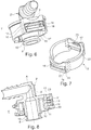
- FIG. 6 On the figures 6 to 8 is shown a tubular end piece 1 'according to a second embodiment, with a ring 5' mounted on a female end piece 2 '.
- the tubular connection 1 ′ is of even simpler structure than in the prior art.
- the female end piece 2 ' comprises a flexible finger 11' fulfilling a double function, the first being as in the first embodiment of authorizing the disconnection of the male end piece 6 from the tubular connector 1 'by performing axial traction on the ring 5 ', the second being a clipping function during the axial interlocking of the ring 5' around the body 3 'of the female end piece 2'.
- the flexible finger 11 ' has a groove 14 "connecting the two shoulders 14 which is oblique, inclined radially inwards.
- the lateral opening 17 of the ring 5 ′ is here delimited on the upper side, in the interlocking direction of the ring 5 ′, by a groove 23 in radial projection which is oblique, inclined radially outwards.
- a body 3 ' with two flexible fingers 11' distributed around the periphery of the body 3 'and a rings 5 'with two lateral openings 17 distributed over the periphery so that when the ring 5' fits around the body 3 'of the female end piece 2', the flexible fingers 11 'are level with the openings side 17.
- the inclined grooves 23 of the ring 5 ' come into contact with the inclined grooves 14 "of the fingers 11' and will press on the grooves 14" flexible fingers 11 ′. These will then retract elastically towards the inside of the body 3 'so as to let the upper part of the ring 5' pass with the grooves 23 around the body 3 '. Then the fingers 11 'will deploy elastically at the level of the lateral openings 17' of the ring 5 'so that the shoulders 14 are positioned at the bottom point of the oblique ramps 18.
- the ramps 18 are protected by edges 24 extending axially outside the ring 5 '.
- these edges protect the fingers 11 'from impacts which may occur on the tubular end piece 1'.
- the tubular connection 1, 1 ′ is compact and has a structure of less complexity compared to the existing connections.
- the ring 5, 5 'surrounding the female end piece 2, 2' makes it possible to protect the tubular end piece 1, 1 'from possible infiltration of dust or other materials into the orifice 4 of the bodies 3, 3'.
- the elements of the tubular connector 1 according to the invention can be made of plastic, for example by injection molding or 3D printing.
- the ring 5, 5' does not include any element which requires flexibility while the female end piece 2, 2 'notably has the fingers 11 notched as flexible elements.
- the ring 5, 5 'and the female end piece 1, 1' in two different materials, in particular it is advantageous to choose a material having a higher hardness for the ring 5, 5 'than for the 'female end 2, 2'.
- the ring 5, 5' surrounding the body 3, 3 'of the female end piece 2, 2' can limit the risks of deformation.
Claims (7)
- Rohrförmiger Anschluss (1, 1'), dadurch gekennzeichnet,
dass er ein weibliches Ansatzstück (2, 2') mit einem hohlen rohrförmigen Korpus (3), der sich gemäß einer axialen Richtung (A) erstreckt und eine axiale Öffnung (4) ausbildet, in die ein mit einem Kragen (7) versehenes männliches Ansatzstück (6) dazu bestimmt ist, axial eingeführt zu werden, umfasst,
dass der hohle Korpus (3) des weiblichen Ansatzstückes (2, 2') ein gezahntes Verrieglungsorgan (11, 11') umfasst, das sich axial entlang des hohlen Korpus (3) erstreckt und das ausgebildet ist, um elastisch radial durch mechanisches Zusammenwirken mit dem Kragen (7) bei dem Einsetzen des männlichen Ansatzstückes (6) in die Öffnung (4) des weiblichen Ansatzstückes (2, 2') deformiert zu werden und sich rückwärtig des Kragens (7) zu verriegeln, wenn das männliche Ansatzstück (6) vollständig in die Öffnung (4) des weiblichen Ansatzstückes (2, 2') eingesetzt ist,
dass er ferner einen zu der Öffnung (4) um das weibliche Ansatzstück (2, 2') koaxial verschiebbar montierten Ringkörper (5, 5') umfasst, welcher eine zu der axialen Richtung querverlaufende und radial von dem hohlen Korpus (3) nach außen geneigte Rampe (18) bildet zum elastischen radialen Deformieren durch Hebelwirkung des Verrieglungsorgans (11, 11'), wenn der Ringkörper (5, 5') eine axiale Betätigung in die Einführrichtung des männlichen Ansatzstückes (6) in das weibliche Ansatzstück (2, 2') derart erfährt, dass das männliche Ansatzstück (6) von dem weiblichen Ansatzstück (2, 2') freigegeben wird. - Rohrförmiger Anschluss (1, 1') nach Anspruch 1, dadurch gekennzeichnet, dass das Verrieglungsorgan (11, 11') zwei gezahnte Stege (11, 11') umfasst, die um die Öffnung (4) des weiblichen Ansatzstückes (2, 2') verteilt sind, wobei jeder gezahnte Steg (11, 11') zwei seitliche Vorsprünge (14) umfasst, und dass der Ringkörper (5, 5') für jeden gezahnten Steg (11, 11') zwei parallele querverlaufende Rampen (18) ausbildet, auf welchen sich jeweils die zwei Vorsprünge (14) der gezahnten Stege (11, 11') abstützen.
- Rohrförmiger Anschluss (1, 1') nach Anspruch 2, dadurch gekennzeichnet, dass der Ringkörper (5, 5') zwei seitliche Durchbrechungen (17) umfasst, die auf dem randseitigen Umfang des Ringkörpers (5, 5') verteilt sind, die jede von zwei parallelen Rampen (18) begrenzt sind.
- Rohrförmiger Anschluss (1, 1') nach Anspruch 3, dadurch gekennzeichnet, dass die zwei parallelen Rampen (18) durch eine Abschnitt (19) aus Verstärkungsmaterial verbunden sind.
- Rohrförmiger Anschluss (1) nach Anspruch 2, dadurch gekennzeichnet, dass die zwei seitlichen Vorsprünge (14) eines gezahnten Stegs (11) Teil einer seitlichen Rippe (14'), die axial in Nuten (20) des Ringkörpers (5) gleitet, sind.
- Rohrförmiger Anschluss (1) nach einem der vorhergehenden Ansprüche, dadurch gekennzeichnet, dass der Ringkörper (5) um das weibliche Ansatzstück (2) durch Klipse (15) gehalten ist.
- Rohrförmiger Anschluss (1') nach einem der Ansprüche 3 bis 4, dadurch gekennzeichnet, dass der Ringkörper (5') auf Höhe der seitlichen Durchbrechungen (17) eine radial vorstehende Rippe (23) umfasst, die ausgebildet ist, um den Ringkörper (5') um das weibliche Ansatzstück (2') zu halten.
Applications Claiming Priority (2)
| Application Number | Priority Date | Filing Date | Title |
|---|---|---|---|
| FR1654186A FR3051240B1 (fr) | 2016-05-11 | 2016-05-11 | Raccord a deconnexion par traction sur une bague |
| PCT/FR2017/050941 WO2017194850A1 (fr) | 2016-05-11 | 2017-04-20 | Raccord a deconnexion par traction sur une bague |
Publications (2)
| Publication Number | Publication Date |
|---|---|
| EP3455535A1 EP3455535A1 (de) | 2019-03-20 |
| EP3455535B1 true EP3455535B1 (de) | 2020-05-13 |
Family
ID=56404148
Family Applications (1)
| Application Number | Title | Priority Date | Filing Date |
|---|---|---|---|
| EP17725299.6A Active EP3455535B1 (de) | 2016-05-11 | 2017-04-20 | Verbinder mit lösung durch ziehen an einem ring |
Country Status (7)
| Country | Link |
|---|---|
| US (1) | US20190285215A1 (de) |
| EP (1) | EP3455535B1 (de) |
| CN (1) | CN108779887A (de) |
| BR (1) | BR112018017288A2 (de) |
| FR (1) | FR3051240B1 (de) |
| RU (1) | RU2018131720A (de) |
| WO (1) | WO2017194850A1 (de) |
Families Citing this family (3)
| Publication number | Priority date | Publication date | Assignee | Title |
|---|---|---|---|---|
| FR3072154B1 (fr) * | 2018-11-12 | 2020-09-04 | Parker Hannifin Emea Sarl | Ensemble de raccordement de conduits de transport de fluide |
| US11498087B2 (en) * | 2019-06-28 | 2022-11-15 | Medmix Switzerland Ag | Connecting device |
| FR3102528B1 (fr) | 2019-10-28 | 2021-10-15 | Sogefi Filtration Spa | Dispositif de raccordement de conduit |
Family Cites Families (10)
| Publication number | Priority date | Publication date | Assignee | Title |
|---|---|---|---|---|
| DE8709151U1 (de) * | 1987-07-02 | 1987-11-12 | Gip Gastrointestinale Produkte Vertriebs Gmbh, 8221 Grabenstaett, De | |
| DE29610487U1 (de) * | 1996-04-22 | 1996-09-12 | Gemi Metallwarenfabrik Gmbh & | Steckverbindungssystem für lösbare Fluidleitungen |
| DE10250421A1 (de) | 2002-10-30 | 2004-05-13 | A. Raymond & Cie | Verbindungselement |
| FR2881811B1 (fr) * | 2005-02-10 | 2007-04-20 | Legris Sa | Dispositif de raccordement instantane avec moyen de verrouillage et/ou de deconnexion |
| DE102005060135A1 (de) * | 2005-12-16 | 2007-07-05 | A. Raymond Et Cie | Kupplung |
| FR2944084B1 (fr) | 2009-04-02 | 2011-05-06 | Hutchinson | Dispositif et procede de raccordement par encliquetage pour circuit de transfert de fluide, et ce circuit l'incorporant |
| US8366154B2 (en) * | 2011-06-15 | 2013-02-05 | Wang Cheng-An | Water pipe connector |
| US9283344B2 (en) * | 2012-01-03 | 2016-03-15 | Carefusion Corporation | Apparatus, system, and method of fluid delivery connection |
| EP2728236B1 (de) * | 2012-11-05 | 2017-04-19 | TI Automotive (Fuldabrück) GmbH | Schnellkupplung |
| US9523453B2 (en) * | 2013-03-20 | 2016-12-20 | Miniature Precision Components, Inc. | Locking quick connect assembly |
-
2016
- 2016-05-11 FR FR1654186A patent/FR3051240B1/fr not_active Expired - Fee Related
-
2017
- 2017-04-20 BR BR112018017288A patent/BR112018017288A2/pt not_active IP Right Cessation
- 2017-04-20 EP EP17725299.6A patent/EP3455535B1/de active Active
- 2017-04-20 WO PCT/FR2017/050941 patent/WO2017194850A1/fr unknown
- 2017-04-20 RU RU2018131720A patent/RU2018131720A/ru not_active Application Discontinuation
- 2017-04-20 CN CN201780017778.5A patent/CN108779887A/zh active Pending
- 2017-04-20 US US16/300,527 patent/US20190285215A1/en not_active Abandoned
Non-Patent Citations (1)
| Title |
|---|
| None * |
Also Published As
| Publication number | Publication date |
|---|---|
| FR3051240A1 (fr) | 2017-11-17 |
| US20190285215A1 (en) | 2019-09-19 |
| CN108779887A (zh) | 2018-11-09 |
| FR3051240B1 (fr) | 2019-09-06 |
| EP3455535A1 (de) | 2019-03-20 |
| RU2018131720A (ru) | 2020-03-05 |
| RU2018131720A3 (de) | 2020-03-05 |
| WO2017194850A1 (fr) | 2017-11-16 |
| BR112018017288A2 (pt) | 2019-01-08 |
Similar Documents
| Publication | Publication Date | Title |
|---|---|---|
| EP0911565B1 (de) | Schnellverbindung zur Verbindung von starren Rohren in einem Anschlussstück | |
| EP3455535B1 (de) | Verbinder mit lösung durch ziehen an einem ring | |
| FR2767376A1 (fr) | Accouplement emboitable pour relier deux conduits de circulation d'un fluide | |
| FR2718822A1 (fr) | Accouplement emboîtable à désaccouplement simplifié, pour relier deux conduits de circulation d'un fluide. | |
| FR2654489A1 (fr) | Organe femelle de raccord de canalisation. | |
| FR2845149A1 (fr) | Dispositif et structure anti-rotation pour tuyau et raccord | |
| FR2840050A1 (fr) | Raccord rapide | |
| WO1999050583A1 (fr) | Raccord encliquetable pour tuyaux | |
| FR2889287A1 (fr) | Connecteur rapide pour fluide | |
| WO2016177985A1 (fr) | Collier de raccordement et dispositif de raccordement de conduits comprenant un tel collier de raccordement | |
| FR3030136B1 (fr) | Module de raccordement electrique | |
| FR2737275A1 (fr) | Raccord de tuyaux antiseparation | |
| FR3073598B1 (fr) | Raccord a deconnexion par traction sur une bague | |
| EP1056969B1 (de) | Rastverbindung für eine rohrleitung | |
| FR3060097B1 (fr) | Dispositif de connexion pour circuit hydraulique | |
| WO2015136161A1 (fr) | Dispositif de raccordement avec un verrou de connexion tournant | |
| EP0452172B1 (de) | Schnellmontageclip für Wärmetauscher an Kraftfahrzeugen | |
| FR2897668A1 (fr) | Raccord rapide a encliquetage | |
| FR3061562B1 (fr) | Dispositif de raccordement amovible pour un guide de lumiere et application dans un vehicule automobile, module a transmission optique pourvu du dispositif | |
| EP2236895A1 (de) | Vorrichtung und Verfahren zum Verbinden durch Einrasten für flüssigkeitsführende Leitungssysteme und ein diese Vorrichtung aufweisendes Leitunssystem | |
| FR3030129A1 (fr) | Borne de connecteur | |
| FR2854675A1 (fr) | Dispositif apte a relier de maniere etanche deux manchons | |
| EP3999766B1 (de) | Kompakte und demontierbare fluidverbindung | |
| EP3999765B1 (de) | Kompakte und demontierbare fluidverbindungsvorrichtung | |
| FR2976645A1 (fr) | Douille d'etancheite destinee a un passe-cable |
Legal Events
| Date | Code | Title | Description |
|---|---|---|---|
| STAA | Information on the status of an ep patent application or granted ep patent |
Free format text: STATUS: UNKNOWN |
|
| STAA | Information on the status of an ep patent application or granted ep patent |
Free format text: STATUS: THE INTERNATIONAL PUBLICATION HAS BEEN MADE |
|
| PUAI | Public reference made under article 153(3) epc to a published international application that has entered the european phase |
Free format text: ORIGINAL CODE: 0009012 |
|
| STAA | Information on the status of an ep patent application or granted ep patent |
Free format text: STATUS: REQUEST FOR EXAMINATION WAS MADE |
|
| 17P | Request for examination filed |
Effective date: 20181211 |
|
| AK | Designated contracting states |
Kind code of ref document: A1 Designated state(s): AL AT BE BG CH CY CZ DE DK EE ES FI FR GB GR HR HU IE IS IT LI LT LU LV MC MK MT NL NO PL PT RO RS SE SI SK SM TR |
|
| AX | Request for extension of the european patent |
Extension state: BA ME |
|
| DAV | Request for validation of the european patent (deleted) | ||
| DAX | Request for extension of the european patent (deleted) | ||
| GRAP | Despatch of communication of intention to grant a patent |
Free format text: ORIGINAL CODE: EPIDOSNIGR1 |
|
| STAA | Information on the status of an ep patent application or granted ep patent |
Free format text: STATUS: GRANT OF PATENT IS INTENDED |
|
| INTG | Intention to grant announced |
Effective date: 20191213 |
|
| RIN1 | Information on inventor provided before grant (corrected) |
Inventor name: BOIS, MATHIAS Inventor name: HAMADENE, SOFIEN |
|
| GRAS | Grant fee paid |
Free format text: ORIGINAL CODE: EPIDOSNIGR3 |
|
| GRAA | (expected) grant |
Free format text: ORIGINAL CODE: 0009210 |
|
| STAA | Information on the status of an ep patent application or granted ep patent |
Free format text: STATUS: THE PATENT HAS BEEN GRANTED |
|
| AK | Designated contracting states |
Kind code of ref document: B1 Designated state(s): AL AT BE BG CH CY CZ DE DK EE ES FI FR GB GR HR HU IE IS IT LI LT LU LV MC MK MT NL NO PL PT RO RS SE SI SK SM TR |
|
| REG | Reference to a national code |
Ref country code: GB Ref legal event code: FG4D Free format text: NOT ENGLISH |
|
| REG | Reference to a national code |
Ref country code: CH Ref legal event code: EP |
|
| REG | Reference to a national code |
Ref country code: DE Ref legal event code: R096 Ref document number: 602017016525 Country of ref document: DE |
|
| REG | Reference to a national code |
Ref country code: AT Ref legal event code: REF Ref document number: 1270741 Country of ref document: AT Kind code of ref document: T Effective date: 20200615 |
|
| REG | Reference to a national code |
Ref country code: LT Ref legal event code: MG4D |
|
| REG | Reference to a national code |
Ref country code: NL Ref legal event code: MP Effective date: 20200513 |
|
| PG25 | Lapsed in a contracting state [announced via postgrant information from national office to epo] |
Ref country code: IS Free format text: LAPSE BECAUSE OF FAILURE TO SUBMIT A TRANSLATION OF THE DESCRIPTION OR TO PAY THE FEE WITHIN THE PRESCRIBED TIME-LIMIT Effective date: 20200913 Ref country code: PT Free format text: LAPSE BECAUSE OF FAILURE TO SUBMIT A TRANSLATION OF THE DESCRIPTION OR TO PAY THE FEE WITHIN THE PRESCRIBED TIME-LIMIT Effective date: 20200914 Ref country code: FI Free format text: LAPSE BECAUSE OF FAILURE TO SUBMIT A TRANSLATION OF THE DESCRIPTION OR TO PAY THE FEE WITHIN THE PRESCRIBED TIME-LIMIT Effective date: 20200513 Ref country code: SE Free format text: LAPSE BECAUSE OF FAILURE TO SUBMIT A TRANSLATION OF THE DESCRIPTION OR TO PAY THE FEE WITHIN THE PRESCRIBED TIME-LIMIT Effective date: 20200513 Ref country code: LT Free format text: LAPSE BECAUSE OF FAILURE TO SUBMIT A TRANSLATION OF THE DESCRIPTION OR TO PAY THE FEE WITHIN THE PRESCRIBED TIME-LIMIT Effective date: 20200513 Ref country code: GR Free format text: LAPSE BECAUSE OF FAILURE TO SUBMIT A TRANSLATION OF THE DESCRIPTION OR TO PAY THE FEE WITHIN THE PRESCRIBED TIME-LIMIT Effective date: 20200814 Ref country code: NO Free format text: LAPSE BECAUSE OF FAILURE TO SUBMIT A TRANSLATION OF THE DESCRIPTION OR TO PAY THE FEE WITHIN THE PRESCRIBED TIME-LIMIT Effective date: 20200813 |
|
| PG25 | Lapsed in a contracting state [announced via postgrant information from national office to epo] |
Ref country code: BG Free format text: LAPSE BECAUSE OF FAILURE TO SUBMIT A TRANSLATION OF THE DESCRIPTION OR TO PAY THE FEE WITHIN THE PRESCRIBED TIME-LIMIT Effective date: 20200813 Ref country code: RS Free format text: LAPSE BECAUSE OF FAILURE TO SUBMIT A TRANSLATION OF THE DESCRIPTION OR TO PAY THE FEE WITHIN THE PRESCRIBED TIME-LIMIT Effective date: 20200513 Ref country code: HR Free format text: LAPSE BECAUSE OF FAILURE TO SUBMIT A TRANSLATION OF THE DESCRIPTION OR TO PAY THE FEE WITHIN THE PRESCRIBED TIME-LIMIT Effective date: 20200513 Ref country code: LV Free format text: LAPSE BECAUSE OF FAILURE TO SUBMIT A TRANSLATION OF THE DESCRIPTION OR TO PAY THE FEE WITHIN THE PRESCRIBED TIME-LIMIT Effective date: 20200513 |
|
| REG | Reference to a national code |
Ref country code: AT Ref legal event code: MK05 Ref document number: 1270741 Country of ref document: AT Kind code of ref document: T Effective date: 20200513 |
|
| PG25 | Lapsed in a contracting state [announced via postgrant information from national office to epo] |
Ref country code: AL Free format text: LAPSE BECAUSE OF FAILURE TO SUBMIT A TRANSLATION OF THE DESCRIPTION OR TO PAY THE FEE WITHIN THE PRESCRIBED TIME-LIMIT Effective date: 20200513 Ref country code: NL Free format text: LAPSE BECAUSE OF FAILURE TO SUBMIT A TRANSLATION OF THE DESCRIPTION OR TO PAY THE FEE WITHIN THE PRESCRIBED TIME-LIMIT Effective date: 20200513 |
|
| PG25 | Lapsed in a contracting state [announced via postgrant information from national office to epo] |
Ref country code: AT Free format text: LAPSE BECAUSE OF FAILURE TO SUBMIT A TRANSLATION OF THE DESCRIPTION OR TO PAY THE FEE WITHIN THE PRESCRIBED TIME-LIMIT Effective date: 20200513 Ref country code: DK Free format text: LAPSE BECAUSE OF FAILURE TO SUBMIT A TRANSLATION OF THE DESCRIPTION OR TO PAY THE FEE WITHIN THE PRESCRIBED TIME-LIMIT Effective date: 20200513 Ref country code: SM Free format text: LAPSE BECAUSE OF FAILURE TO SUBMIT A TRANSLATION OF THE DESCRIPTION OR TO PAY THE FEE WITHIN THE PRESCRIBED TIME-LIMIT Effective date: 20200513 Ref country code: EE Free format text: LAPSE BECAUSE OF FAILURE TO SUBMIT A TRANSLATION OF THE DESCRIPTION OR TO PAY THE FEE WITHIN THE PRESCRIBED TIME-LIMIT Effective date: 20200513 Ref country code: ES Free format text: LAPSE BECAUSE OF FAILURE TO SUBMIT A TRANSLATION OF THE DESCRIPTION OR TO PAY THE FEE WITHIN THE PRESCRIBED TIME-LIMIT Effective date: 20200513 Ref country code: CZ Free format text: LAPSE BECAUSE OF FAILURE TO SUBMIT A TRANSLATION OF THE DESCRIPTION OR TO PAY THE FEE WITHIN THE PRESCRIBED TIME-LIMIT Effective date: 20200513 Ref country code: RO Free format text: LAPSE BECAUSE OF FAILURE TO SUBMIT A TRANSLATION OF THE DESCRIPTION OR TO PAY THE FEE WITHIN THE PRESCRIBED TIME-LIMIT Effective date: 20200513 Ref country code: IT Free format text: LAPSE BECAUSE OF FAILURE TO SUBMIT A TRANSLATION OF THE DESCRIPTION OR TO PAY THE FEE WITHIN THE PRESCRIBED TIME-LIMIT Effective date: 20200513 |
|
| REG | Reference to a national code |
Ref country code: DE Ref legal event code: R097 Ref document number: 602017016525 Country of ref document: DE |
|
| PG25 | Lapsed in a contracting state [announced via postgrant information from national office to epo] |
Ref country code: SK Free format text: LAPSE BECAUSE OF FAILURE TO SUBMIT A TRANSLATION OF THE DESCRIPTION OR TO PAY THE FEE WITHIN THE PRESCRIBED TIME-LIMIT Effective date: 20200513 Ref country code: PL Free format text: LAPSE BECAUSE OF FAILURE TO SUBMIT A TRANSLATION OF THE DESCRIPTION OR TO PAY THE FEE WITHIN THE PRESCRIBED TIME-LIMIT Effective date: 20200513 |
|
| PLBE | No opposition filed within time limit |
Free format text: ORIGINAL CODE: 0009261 |
|
| STAA | Information on the status of an ep patent application or granted ep patent |
Free format text: STATUS: NO OPPOSITION FILED WITHIN TIME LIMIT |
|
| 26N | No opposition filed |
Effective date: 20210216 |
|
| PG25 | Lapsed in a contracting state [announced via postgrant information from national office to epo] |
Ref country code: SI Free format text: LAPSE BECAUSE OF FAILURE TO SUBMIT A TRANSLATION OF THE DESCRIPTION OR TO PAY THE FEE WITHIN THE PRESCRIBED TIME-LIMIT Effective date: 20200513 |
|
| PG25 | Lapsed in a contracting state [announced via postgrant information from national office to epo] |
Ref country code: MC Free format text: LAPSE BECAUSE OF FAILURE TO SUBMIT A TRANSLATION OF THE DESCRIPTION OR TO PAY THE FEE WITHIN THE PRESCRIBED TIME-LIMIT Effective date: 20200513 |
|
| GBPC | Gb: european patent ceased through non-payment of renewal fee |
Effective date: 20210420 |
|
| PG25 | Lapsed in a contracting state [announced via postgrant information from national office to epo] |
Ref country code: LU Free format text: LAPSE BECAUSE OF NON-PAYMENT OF DUE FEES Effective date: 20210420 |
|
| REG | Reference to a national code |
Ref country code: BE Ref legal event code: MM Effective date: 20210430 |
|
| PG25 | Lapsed in a contracting state [announced via postgrant information from national office to epo] |
Ref country code: GB Free format text: LAPSE BECAUSE OF NON-PAYMENT OF DUE FEES Effective date: 20210420 Ref country code: LI Free format text: LAPSE BECAUSE OF NON-PAYMENT OF DUE FEES Effective date: 20210430 Ref country code: CH Free format text: LAPSE BECAUSE OF NON-PAYMENT OF DUE FEES Effective date: 20210430 |
|
| PG25 | Lapsed in a contracting state [announced via postgrant information from national office to epo] |
Ref country code: IE Free format text: LAPSE BECAUSE OF NON-PAYMENT OF DUE FEES Effective date: 20210420 |
|
| PG25 | Lapsed in a contracting state [announced via postgrant information from national office to epo] |
Ref country code: BE Free format text: LAPSE BECAUSE OF NON-PAYMENT OF DUE FEES Effective date: 20210430 |
|
| PG25 | Lapsed in a contracting state [announced via postgrant information from national office to epo] |
Ref country code: CY Free format text: LAPSE BECAUSE OF FAILURE TO SUBMIT A TRANSLATION OF THE DESCRIPTION OR TO PAY THE FEE WITHIN THE PRESCRIBED TIME-LIMIT Effective date: 20200513 |
|
| P01 | Opt-out of the competence of the unified patent court (upc) registered |
Effective date: 20230526 |
|
| PG25 | Lapsed in a contracting state [announced via postgrant information from national office to epo] |
Ref country code: HU Free format text: LAPSE BECAUSE OF FAILURE TO SUBMIT A TRANSLATION OF THE DESCRIPTION OR TO PAY THE FEE WITHIN THE PRESCRIBED TIME-LIMIT; INVALID AB INITIO Effective date: 20170420 |
|
| PGFP | Annual fee paid to national office [announced via postgrant information from national office to epo] |
Ref country code: FR Payment date: 20230424 Year of fee payment: 7 Ref country code: DE Payment date: 20230420 Year of fee payment: 7 |
|
| PG25 | Lapsed in a contracting state [announced via postgrant information from national office to epo] |
Ref country code: MK Free format text: LAPSE BECAUSE OF FAILURE TO SUBMIT A TRANSLATION OF THE DESCRIPTION OR TO PAY THE FEE WITHIN THE PRESCRIBED TIME-LIMIT Effective date: 20200513 |