EP3454989B1 - Boitier de support de cônes de prélèvement pour système de pipetage - Google Patents
Boitier de support de cônes de prélèvement pour système de pipetage Download PDFInfo
- Publication number
- EP3454989B1 EP3454989B1 EP17721739.5A EP17721739A EP3454989B1 EP 3454989 B1 EP3454989 B1 EP 3454989B1 EP 17721739 A EP17721739 A EP 17721739A EP 3454989 B1 EP3454989 B1 EP 3454989B1
- Authority
- EP
- European Patent Office
- Prior art keywords
- casing
- mating
- notch
- stacking direction
- members
- Prior art date
- Legal status (The legal status is an assumption and is not a legal conclusion. Google has not performed a legal analysis and makes no representation as to the accuracy of the status listed.)
- Active
Links
Images


Classifications
-
- B—PERFORMING OPERATIONS; TRANSPORTING
- B01—PHYSICAL OR CHEMICAL PROCESSES OR APPARATUS IN GENERAL
- B01L—CHEMICAL OR PHYSICAL LABORATORY APPARATUS FOR GENERAL USE
- B01L9/00—Supporting devices; Holding devices
- B01L9/54—Supports specially adapted for pipettes and burettes
- B01L9/543—Supports specially adapted for pipettes and burettes for disposable pipette tips, e.g. racks or cassettes
-
- B—PERFORMING OPERATIONS; TRANSPORTING
- B01—PHYSICAL OR CHEMICAL PROCESSES OR APPARATUS IN GENERAL
- B01L—CHEMICAL OR PHYSICAL LABORATORY APPARATUS FOR GENERAL USE
- B01L2200/00—Solutions for specific problems relating to chemical or physical laboratory apparatus
- B01L2200/02—Adapting objects or devices to another
- B01L2200/025—Align devices or objects to ensure defined positions relative to each other
-
- B—PERFORMING OPERATIONS; TRANSPORTING
- B01—PHYSICAL OR CHEMICAL PROCESSES OR APPARATUS IN GENERAL
- B01L—CHEMICAL OR PHYSICAL LABORATORY APPARATUS FOR GENERAL USE
- B01L2300/00—Additional constructional details
- B01L2300/08—Geometry, shape and general structure
- B01L2300/0848—Specific forms of parts of containers
- B01L2300/0858—Side walls
-
- B—PERFORMING OPERATIONS; TRANSPORTING
- B01—PHYSICAL OR CHEMICAL PROCESSES OR APPARATUS IN GENERAL
- B01L—CHEMICAL OR PHYSICAL LABORATORY APPARATUS FOR GENERAL USE
- B01L2300/00—Additional constructional details
- B01L2300/08—Geometry, shape and general structure
- B01L2300/0893—Geometry, shape and general structure having a very large number of wells, microfabricated wells
Definitions
- the invention relates to the field of sampling cone support boxes intended for pipetting systems such as robots, automats, or sampling pipettes. These boxes are conventionally called "racks”.
- Such boxes are intended to carry sampling cones before they are fitted onto the pipetting system, for example on the tips of a pipetting robot or on the tips of a multichannel, manual or motorized.
- the pitch between the housing orifices of the sampling cones is such that it coincides with the pitch of the tips of the pipetting system, to allow easy insertion of these tips into the cones.
- the boxes fitted with cones are stacked on top of each other.
- the hollowed-out housing is removed from the stack and gives way to a lower housing filled with other cones.
- the stack of boxes is caused to be manipulated by the operator, so that it is usually preferable to provide coupling means between the boxes. bunk.
- the transition from one housing to another by the operator is effected by actuating the coupling means to unlock them, and thus allow the extraction of one of the two housings.
- the invention therefore aims to respond at least partially to the problem identified above, relating to the embodiments of the prior art.
- each of the first and second opposite sides is equipped with a female coupling member as well as with a male coupling member arranged substantially symmetrically on either side of said median notional plane, the two female organs for coupling the first and second opposite flanks being arranged on the same side of the median notional plane and the two male members for coupling the first and second opposite flanks being arranged on the other side of the median fictional plane, and said male and female coupling members are designed so that when two identical support housings are stacked in the stacking direction with an upper housing and a lower housing both having their male members on the same side of the notional plane middle, the upper case adopts a posed position in which it is not retained by the lower case in the stacking direction, and also designed so that when the upper case and the lower case have their male coupling members respectively on either side of the notional plane middle, the upper housing adopts a retained position in which its two male coupling members cooperate respectively with the two female coupling members of the lower housing.
- the invention proposes an original solution making it possible to keep the same and unique design of housings, while being able to arrange them in the posed position or in the retained position, depending on the intended use.
- This feature makes it easier to manufacture the boxes and simplifies the management of the latter by users.
- it is no longer necessary to identify the type of case manufactured, or to choose from two separate stacking paths. This advantageously results in a great simplification of the production operations, and this generates substantial gains in terms of production time and programming development, etc.
- the invention furthermore presents at least any one of the following optional technical characteristics, taken individually or in combination.
- Each male coupling member comprises a tab pivotally mounted on its associated flank by means of a pivot connection with an axis substantially orthogonal to the stacking direction, the tab having on either side of the pivot connection a gripping portion, as well as a hooking portion ending in a notch.
- Said pivot connection is produced by two cords of material elastically deformable in torsion, the two cords of material being aligned with each other along the axis of the pivot connection.
- the gripping portion projects upwards beyond its associated flank, and said notch is arranged substantially at a low end of this flank.
- the female member has in the upper part a ramp allowing, during a relative displacement of the upper housing towards the lower housing in the direction stacking, to rotate its associated male member around said pivot link by displacement of the notch along the ramp, before automatic insertion of the notch in the female member after this notch has left said ramp.
- said automatic insertion of the notch in the female coupling member is effected by pivoting of the male coupling member caused by a release of energy previously stored by the pivot link, during movement of the notch along the ramp.
- this insertion can be carried out not automatically, but manually by pressing on the gripping portions of the legs, then by releasing them.
- Each female coupling member is arranged substantially at a high end of its associated flank, near a junction with the support for sampling cones.
- the support has 96 holes for housing the sampling cones.
- a different number of orifices can be provided, without departing from the scope of the invention.
- the subject of the invention is also an assembly comprising several identical housings such as that described above, said housings being stacked in the stacking direction, in the posed position or in the retained position.
- the assembly preferably comprises a hollow bottom arranged at the base of the stack of boxes, said hollow bottom comprising female members for coupling with the lowest case in the stack.
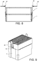
- an assembly 100 is shown according to a preferred embodiment of the invention, this assembly corresponding to a stack of boxes for supporting sampling cones, for pipetting system.
- the boxes 1 are superimposed in a stacking direction 2, corresponding here to the vertical direction. According to a specific feature of the invention which will be detailed below, the boxes 1 of the stack can either be simply placed one on top of the other, or retained to each other in the direction of stacking 2.
- the boxes 1 are intended to contain sampling cones (not shown), also called consumables.
- sampling cones also called consumables.
- the figures 2 to 4 illustrate one of the boxes 1 of the stack, which all have an identical design.
- the housing 1, made in one piece, has an overall parallelepiped shape, hollow and comprising an upper partition which fulfills a support function for consumables.
- This support 10 is arranged in a plane orthogonal to the stacking direction 1, and equipped with orifices 12 for housing the sampling cones.
- it is for example 96 orifices 12 distributed in rows and columns, in the manner of a matrix.
- the pitch between the orifices 12 is provided to coincide with the pitch of the tips of the pipetting system, to allow easy insertion of these tips in the cones.
- the housing 1 extends in length in a longitudinal direction 6 and in width in a transverse direction 8, the three directions 2, 6, 8 being orthogonal to each other.
- the housing 1 comprises four flanks, including a first and a second opposite flanks 14a, 14b, integral with the support 10 and crossed by a median imaginary plane P integrating the stacking direction 2. Consequently, each of these two flanks 14a, 14b opposite in direction 6 extends in a transverse plane, defined by the two directions 2 and 8. Two other flanks 16a, 16b opposite in direction 8 complete the contour of the support 10, each extending in a longitudinal plane defined by the two directions 2 and 6.
- One of the features of the invention resides in the design of coupling means between the successive housings, these means being able to be active or passive depending on the relative orientation of the housings in the stack, as will be explained below. after.
- Each of the first and second opposite sides 14a, 14b is equipped with a female coupling member 18, in the form of a single slot opening outwards in the direction 6.
- the female member 18 is arranged substantially at the level d 'an upper end of the sidewall on which it is located, near a junction with the support 10.
- the slot is delimited in the upper part by a ramp 19 which extends outwards in direction 6, going towards the bottom.
- Each of the first and second opposite flanks 14a, 14b is also equipped with a male coupling member 20, taking the form of a lug pivotally mounted on its associated flank, by means of a pivot connection 22.
- the connection pivot 22 has a pivot axis 23 substantially orthogonal to the stacking direction 2, and parallel to the transverse direction 8. It is produced by two cords of material 26 elastically deformable in torsion along the axis 23, and aligned one with the other along this same axis.
- the tab 20 has a height greater than that of the housing 1.
- the notch 34 projects in the direction of the interior of the housing 1, in the direction 6 as opposed to the tab 20 which extends generally in the stacking direction 2.
- each flank 14a, 14b the female member 18 and the male member 20 are arranged substantially symmetrically on either side of the fictitious median plane P.
- the two female coupling members 18 of the first and second flanks opposite 14a, 14b are arranged on the same side of the median fictitious plane P, and the two male coupling members 20 of these same flanks are arranged on the other side of the median fictitious plane P.
- the upper housing 1 adopts a position placed on the lower housing, without being retained in the stacking direction 2.
- the male members 20 of the two housings are on the same side of the median notional plane P, and therefore overlap two by two in direction 6, as is also visible on the figure 5a .
- This type of stacking in which the boxes 1 adopt the same angular position relative to a central stacking axis, is preferably retained in the case of the use of the assembly 100 by robots / automats, allowing the realization automated pipetting operations.
- the upper housing 1 adopts a retained position relative to the lower housing 1, the retention being effected using the aforementioned coupling means.
- the two housings 1 instead of adopting the same angular position, have an angular position offset by 180 ° relative to each other in relation to the central stacking axis, which leads the organs male of the two housings to be located respectively on either side of the median notional plane P. This thus allows the upper housing 1 to have its two male members 20 cooperating respectively with the two female members 18 of the lower housing, as is also shown on the figure 6a at the sides 14a.
- This type of stack is preferably retained in the case of manual pipetting operations, with a sampling pipette. This allows the operator to move the stack of boxes 1 without risking to accidentally separate them from each other.
- FIGS 7a to 7c illustrate a way of automatically assembling two boxes 1 one on the other, simply by moving them one towards the other in the stacking direction 2. They are first aligned in the direction 2 as shown on the figure 7a , until the notch 34 abuts against the ramp 19 of the female member 18, as shown on the figure 7b .
- the continuation of the relative displacement carried out for example by simple pressure on the upper casing downwards, causes the notch 34 to move along the ramp 19 provided for this purpose.
- the purpose of this ramp 19 is to spread the attachment portion 32 outward, in the direction 6, as illustrated in the figure 7c . This is possible thanks to the pivoting of the tab 20 around the connection 22, along the pivot axis 23.
- the two beads of material forming the pivot connection 22 elastically deform in torsion along the axis 23. Therefore, when the pressure down brings the notch 34 opposite. the slot defined by the female member 18, at the outlet of the ramp 19, this notch 34 is inserted automatically into the female member 18 thanks to the release of energy previously stored by the pivot link. The retained position is then obtained, this being also known as the clipped position.
- the two housings 1 can be coupled by exerting pressure on the gripping portions 30 so as to bring them inward, then releasing this pressure after having brought the notches opposite the female organs.
- the same pressure 40 shown diagrammatically on the figure 8 can be exerted on the gripping portions 30, in order to remove the notches outside the female organs.
- the upper housing can be extracted upwards, or the lower housing can be extracted downwards, so as to unstack.
- FIGS 9 to 11 illustrate the fact that the upper edge of the hollow bottom 4 has female coupling members 18 'identical or similar to those housings 1, so as to be able to cooperate with the male members 20 of the lowest housing 1 in the stack.
- a ramp system 19 ′ allows the automatic insertion of the notches of the organs 20 into the female organs 18 ′.
Landscapes
- Health & Medical Sciences (AREA)
- Clinical Laboratory Science (AREA)
- Chemical & Material Sciences (AREA)
- Chemical Kinetics & Catalysis (AREA)
- Stackable Containers (AREA)
- Sampling And Sample Adjustment (AREA)
- Devices For Use In Laboratory Experiments (AREA)
Priority Applications (1)
| Application Number | Priority Date | Filing Date | Title |
|---|---|---|---|
| PL17721739T PL3454989T3 (pl) | 2016-05-12 | 2017-05-10 | Skrzynka podtrzymująca stożki probiercze do systemu do pipetowania |
Applications Claiming Priority (2)
| Application Number | Priority Date | Filing Date | Title |
|---|---|---|---|
| FR1654249A FR3051125B1 (fr) | 2016-05-12 | 2016-05-12 | Boitier de support de cones de prelevement pour systeme de pipetage |
| PCT/EP2017/061121 WO2017194575A1 (fr) | 2016-05-12 | 2017-05-10 | Boitier de support de cones de prelevement pour systeme de pipetage |
Publications (2)
| Publication Number | Publication Date |
|---|---|
| EP3454989A1 EP3454989A1 (fr) | 2019-03-20 |
| EP3454989B1 true EP3454989B1 (fr) | 2020-02-12 |
Family
ID=56148571
Family Applications (1)
| Application Number | Title | Priority Date | Filing Date |
|---|---|---|---|
| EP17721739.5A Active EP3454989B1 (fr) | 2016-05-12 | 2017-05-10 | Boitier de support de cônes de prélèvement pour système de pipetage |
Country Status (10)
| Country | Link |
|---|---|
| US (1) | US10835902B2 (https=) |
| EP (1) | EP3454989B1 (https=) |
| JP (1) | JP6929303B2 (https=) |
| KR (1) | KR20190008217A (https=) |
| CN (1) | CN109070085B (https=) |
| CA (1) | CA3024403A1 (https=) |
| ES (1) | ES2789677T3 (https=) |
| FR (1) | FR3051125B1 (https=) |
| PL (1) | PL3454989T3 (https=) |
| WO (1) | WO2017194575A1 (https=) |
Families Citing this family (2)
| Publication number | Priority date | Publication date | Assignee | Title |
|---|---|---|---|---|
| EP3960296A1 (en) | 2020-08-26 | 2022-03-02 | Sartorius Biohit Liquid Handling Oy | A holder, a set of parts, and a method of manipulating holders of laboratory consumables |
| CN116409527B (zh) * | 2021-12-31 | 2025-10-21 | 深圳市裕同包装科技股份有限公司 | 盒体及包装盒 |
Family Cites Families (14)
| Publication number | Priority date | Publication date | Assignee | Title |
|---|---|---|---|---|
| US2868430A (en) * | 1956-08-07 | 1959-01-13 | Container Corp | Stacking paperboard tray |
| DE9216674U1 (de) * | 1992-12-08 | 1993-03-18 | Steinbrenner, Bernd, Dr., 6901 Wiesenbach | Vorrichtung zum Bereitstellen vorzugsweise sterilisierter Pipettenspitzen |
| US5642816A (en) * | 1995-10-25 | 1997-07-01 | Rainin Instrument Co., Inc. | Pipette tip rack refill plate hold down apparatus |
| US5882603A (en) * | 1997-10-15 | 1999-03-16 | Point Plastics Incorporated | Support rack for pipette tips |
| US7232038B2 (en) * | 2004-04-27 | 2007-06-19 | Whitney Steven G | Disposable test tube rack |
| US7658887B2 (en) * | 2004-09-02 | 2010-02-09 | Scientific Specialties, Inc. | Pipette tip grid with lock mechanism |
| TWM399472U (en) * | 2008-09-09 | 2011-03-01 | Molex Inc | A connector |
| JP6049235B2 (ja) * | 2009-12-10 | 2016-12-21 | エフ.ホフマン−ラ ロシュ アーゲーF. Hoffmann−La Roche Aktiengesellschaft | 組み合わせ先端部用ラック |
| US8906327B2 (en) * | 2011-04-08 | 2014-12-09 | Molecular Bioproducts, Inc. | Pipette tip stacking tray |
| ES2692293T3 (es) * | 2011-04-21 | 2018-12-03 | Becton Dickinson France | Embalaje para contenedores médicos |
| EP2623204A1 (en) * | 2012-02-03 | 2013-08-07 | F. Hoffmann-La Roche AG | Sample handling system |
| US9366686B2 (en) * | 2013-10-18 | 2016-06-14 | Bio-Tek Instruments, Inc. | Microplate stacker for plates with lids |
| CN104554989B (zh) * | 2013-12-23 | 2021-01-08 | 上海鸿研物流技术有限公司 | 带托盘的堆叠装置 |
| EP3006110A1 (en) * | 2014-10-10 | 2016-04-13 | F.Hoffmann-La Roche Ag | Rack |
-
2016
- 2016-05-12 FR FR1654249A patent/FR3051125B1/fr not_active Expired - Fee Related
-
2017
- 2017-05-10 JP JP2018558763A patent/JP6929303B2/ja active Active
- 2017-05-10 US US16/099,092 patent/US10835902B2/en active Active
- 2017-05-10 KR KR1020187032627A patent/KR20190008217A/ko not_active Abandoned
- 2017-05-10 PL PL17721739T patent/PL3454989T3/pl unknown
- 2017-05-10 WO PCT/EP2017/061121 patent/WO2017194575A1/fr not_active Ceased
- 2017-05-10 EP EP17721739.5A patent/EP3454989B1/fr active Active
- 2017-05-10 CA CA3024403A patent/CA3024403A1/fr active Pending
- 2017-05-10 ES ES17721739T patent/ES2789677T3/es active Active
- 2017-05-10 CN CN201780028265.4A patent/CN109070085B/zh active Active
Non-Patent Citations (1)
| Title |
|---|
| None * |
Also Published As
| Publication number | Publication date |
|---|---|
| CN109070085B (zh) | 2020-12-08 |
| CN109070085A (zh) | 2018-12-21 |
| FR3051125B1 (fr) | 2018-06-15 |
| ES2789677T3 (es) | 2020-10-26 |
| WO2017194575A1 (fr) | 2017-11-16 |
| US10835902B2 (en) | 2020-11-17 |
| KR20190008217A (ko) | 2019-01-23 |
| JP2019516544A (ja) | 2019-06-20 |
| FR3051125A1 (fr) | 2017-11-17 |
| PL3454989T3 (pl) | 2020-07-13 |
| CA3024403A1 (fr) | 2017-11-16 |
| JP6929303B2 (ja) | 2021-09-01 |
| EP3454989A1 (fr) | 2019-03-20 |
| US20190201908A1 (en) | 2019-07-04 |
Similar Documents
| Publication | Publication Date | Title |
|---|---|---|
| EP2464580B1 (fr) | Coiffe de verrouillage pour recipient a col avec une capsule a pattes de fixation | |
| EP0402281B1 (fr) | Elément de raccord pour tubes annelés | |
| EP3175283B1 (fr) | Paire de lunettes modulable | |
| EP2922760B1 (fr) | Boite en carton avec languette de centrage, flan, ensemble de flans et procede pour la realisation d'une telle boite | |
| EP3454989B1 (fr) | Boitier de support de cônes de prélèvement pour système de pipetage | |
| EP1988001B1 (fr) | Brouette ou analogue empilable par sous-éléments prémontés | |
| EP3112227A1 (fr) | Adaptateur pour relier un balai d'essuie-glace à un bras d'entraînement | |
| EP2819810B1 (fr) | Système comportant un pion de positionnement et de centrage pour lentille ophtalmique, un organe d'assujettissement et un outil pour le positionnement dudit organe d'assujettissement sur ledit pion de positionnement et de centrage | |
| EP0827890B1 (fr) | Dispositif d'accrochage d'une nacelle sur une poussette pour enfant, poussette équipée d'un tel dispostif, support pour enfant équipé d'un tel dispositif | |
| EP3034376A1 (fr) | Ensemble de transport de brouettes démontables | |
| FR2887836A1 (fr) | Verrou pour solidariser une extremite spherique de commande de frein a un poussoir de pedale de frein de vehicule automobile | |
| FR3040555A1 (fr) | Troncon de chemin de cables, chemin de cables et procede de montage associes | |
| WO2004041685A2 (fr) | Maillon pour tapis de convoyage d'objets quelconques | |
| EP2862440B1 (fr) | Rouleau à déboiter | |
| EP2494861A1 (fr) | Châssis de semoir pouvant occuper une position de transport et une position de travail, susceptible de prendre une configuration rigide ou flottante | |
| EP3721742A1 (fr) | Parasol a deploiement automatique | |
| FR3131250A3 (fr) | Moyens de fixation d’une roue de bac de collecte de déchets | |
| WO2014177462A1 (fr) | Cadre pour tour d'etaiement comportant des moyens elastiques de verrouillage et procede de montage dudit cadre | |
| EP1977642B1 (fr) | Dispositif pour la fixation d'un objet au moins partiellement plat sur la paroi d'un récipient | |
| EP2364919B1 (fr) | Dispositif de calage d'objet dans un conteneur | |
| WO2024022731A1 (fr) | Véhicule équipé de barres de toit modulables et inviolables | |
| EP3642124B1 (fr) | Ensemble comportant une palette de transport de chariots et un ou plusieurs chariots | |
| EP3642125B1 (fr) | Palette de transport de chariots comportant des organes de blocage et ensemble comportant une palette et au moins un chariot | |
| FR3027884A3 (fr) | Conteneur empilable pour la collecte des dechets menagers | |
| FR3131577A1 (fr) | Moyens de fixation d’une roue de bac de collecte de déchets |
Legal Events
| Date | Code | Title | Description |
|---|---|---|---|
| STAA | Information on the status of an ep patent application or granted ep patent |
Free format text: STATUS: UNKNOWN |
|
| STAA | Information on the status of an ep patent application or granted ep patent |
Free format text: STATUS: THE INTERNATIONAL PUBLICATION HAS BEEN MADE |
|
| PUAI | Public reference made under article 153(3) epc to a published international application that has entered the european phase |
Free format text: ORIGINAL CODE: 0009012 |
|
| STAA | Information on the status of an ep patent application or granted ep patent |
Free format text: STATUS: REQUEST FOR EXAMINATION WAS MADE |
|
| 17P | Request for examination filed |
Effective date: 20181119 |
|
| AK | Designated contracting states |
Kind code of ref document: A1 Designated state(s): AL AT BE BG CH CY CZ DE DK EE ES FI FR GB GR HR HU IE IS IT LI LT LU LV MC MK MT NL NO PL PT RO RS SE SI SK SM TR |
|
| AX | Request for extension of the european patent |
Extension state: BA ME |
|
| DAV | Request for validation of the european patent (deleted) | ||
| DAX | Request for extension of the european patent (deleted) | ||
| GRAP | Despatch of communication of intention to grant a patent |
Free format text: ORIGINAL CODE: EPIDOSNIGR1 |
|
| STAA | Information on the status of an ep patent application or granted ep patent |
Free format text: STATUS: GRANT OF PATENT IS INTENDED |
|
| INTG | Intention to grant announced |
Effective date: 20190930 |
|
| GRAS | Grant fee paid |
Free format text: ORIGINAL CODE: EPIDOSNIGR3 |
|
| GRAA | (expected) grant |
Free format text: ORIGINAL CODE: 0009210 |
|
| STAA | Information on the status of an ep patent application or granted ep patent |
Free format text: STATUS: THE PATENT HAS BEEN GRANTED |
|
| AK | Designated contracting states |
Kind code of ref document: B1 Designated state(s): AL AT BE BG CH CY CZ DE DK EE ES FI FR GB GR HR HU IE IS IT LI LT LU LV MC MK MT NL NO PL PT RO RS SE SI SK SM TR |
|
| REG | Reference to a national code |
Ref country code: GB Ref legal event code: FG4D Free format text: NOT ENGLISH |
|
| REG | Reference to a national code |
Ref country code: CH Ref legal event code: EP |
|
| REG | Reference to a national code |
Ref country code: AT Ref legal event code: REF Ref document number: 1231387 Country of ref document: AT Kind code of ref document: T Effective date: 20200215 |
|
| REG | Reference to a national code |
Ref country code: IE Ref legal event code: FG4D Free format text: LANGUAGE OF EP DOCUMENT: FRENCH |
|
| REG | Reference to a national code |
Ref country code: DE Ref legal event code: R096 Ref document number: 602017011680 Country of ref document: DE |
|
| REG | Reference to a national code |
Ref country code: CH Ref legal event code: NV Representative=s name: BOVARD AG PATENT- UND MARKENANWAELTE, CH |
|
| REG | Reference to a national code |
Ref country code: FI Ref legal event code: FGE |
|
| PG25 | Lapsed in a contracting state [announced via postgrant information from national office to epo] |
Ref country code: NO Free format text: LAPSE BECAUSE OF FAILURE TO SUBMIT A TRANSLATION OF THE DESCRIPTION OR TO PAY THE FEE WITHIN THE PRESCRIBED TIME-LIMIT Effective date: 20200512 Ref country code: RS Free format text: LAPSE BECAUSE OF FAILURE TO SUBMIT A TRANSLATION OF THE DESCRIPTION OR TO PAY THE FEE WITHIN THE PRESCRIBED TIME-LIMIT Effective date: 20200212 |
|
| REG | Reference to a national code |
Ref country code: LT Ref legal event code: MG4D |
|
| REG | Reference to a national code |
Ref country code: NL Ref legal event code: MP Effective date: 20200212 |
|
| PG25 | Lapsed in a contracting state [announced via postgrant information from national office to epo] |
Ref country code: HR Free format text: LAPSE BECAUSE OF FAILURE TO SUBMIT A TRANSLATION OF THE DESCRIPTION OR TO PAY THE FEE WITHIN THE PRESCRIBED TIME-LIMIT Effective date: 20200212 Ref country code: SE Free format text: LAPSE BECAUSE OF FAILURE TO SUBMIT A TRANSLATION OF THE DESCRIPTION OR TO PAY THE FEE WITHIN THE PRESCRIBED TIME-LIMIT Effective date: 20200212 Ref country code: LV Free format text: LAPSE BECAUSE OF FAILURE TO SUBMIT A TRANSLATION OF THE DESCRIPTION OR TO PAY THE FEE WITHIN THE PRESCRIBED TIME-LIMIT Effective date: 20200212 Ref country code: GR Free format text: LAPSE BECAUSE OF FAILURE TO SUBMIT A TRANSLATION OF THE DESCRIPTION OR TO PAY THE FEE WITHIN THE PRESCRIBED TIME-LIMIT Effective date: 20200513 Ref country code: IS Free format text: LAPSE BECAUSE OF FAILURE TO SUBMIT A TRANSLATION OF THE DESCRIPTION OR TO PAY THE FEE WITHIN THE PRESCRIBED TIME-LIMIT Effective date: 20200612 Ref country code: BG Free format text: LAPSE BECAUSE OF FAILURE TO SUBMIT A TRANSLATION OF THE DESCRIPTION OR TO PAY THE FEE WITHIN THE PRESCRIBED TIME-LIMIT Effective date: 20200512 |
|
| PG25 | Lapsed in a contracting state [announced via postgrant information from national office to epo] |
Ref country code: NL Free format text: LAPSE BECAUSE OF FAILURE TO SUBMIT A TRANSLATION OF THE DESCRIPTION OR TO PAY THE FEE WITHIN THE PRESCRIBED TIME-LIMIT Effective date: 20200212 |
|
| REG | Reference to a national code |
Ref country code: ES Ref legal event code: FG2A Ref document number: 2789677 Country of ref document: ES Kind code of ref document: T3 Effective date: 20201026 |
|
| PG25 | Lapsed in a contracting state [announced via postgrant information from national office to epo] |
Ref country code: CZ Free format text: LAPSE BECAUSE OF FAILURE TO SUBMIT A TRANSLATION OF THE DESCRIPTION OR TO PAY THE FEE WITHIN THE PRESCRIBED TIME-LIMIT Effective date: 20200212 Ref country code: SM Free format text: LAPSE BECAUSE OF FAILURE TO SUBMIT A TRANSLATION OF THE DESCRIPTION OR TO PAY THE FEE WITHIN THE PRESCRIBED TIME-LIMIT Effective date: 20200212 Ref country code: RO Free format text: LAPSE BECAUSE OF FAILURE TO SUBMIT A TRANSLATION OF THE DESCRIPTION OR TO PAY THE FEE WITHIN THE PRESCRIBED TIME-LIMIT Effective date: 20200212 Ref country code: EE Free format text: LAPSE BECAUSE OF FAILURE TO SUBMIT A TRANSLATION OF THE DESCRIPTION OR TO PAY THE FEE WITHIN THE PRESCRIBED TIME-LIMIT Effective date: 20200212 Ref country code: DK Free format text: LAPSE BECAUSE OF FAILURE TO SUBMIT A TRANSLATION OF THE DESCRIPTION OR TO PAY THE FEE WITHIN THE PRESCRIBED TIME-LIMIT Effective date: 20200212 Ref country code: LT Free format text: LAPSE BECAUSE OF FAILURE TO SUBMIT A TRANSLATION OF THE DESCRIPTION OR TO PAY THE FEE WITHIN THE PRESCRIBED TIME-LIMIT Effective date: 20200212 Ref country code: PT Free format text: LAPSE BECAUSE OF FAILURE TO SUBMIT A TRANSLATION OF THE DESCRIPTION OR TO PAY THE FEE WITHIN THE PRESCRIBED TIME-LIMIT Effective date: 20200705 Ref country code: SK Free format text: LAPSE BECAUSE OF FAILURE TO SUBMIT A TRANSLATION OF THE DESCRIPTION OR TO PAY THE FEE WITHIN THE PRESCRIBED TIME-LIMIT Effective date: 20200212 |
|
| REG | Reference to a national code |
Ref country code: DE Ref legal event code: R097 Ref document number: 602017011680 Country of ref document: DE |
|
| REG | Reference to a national code |
Ref country code: AT Ref legal event code: MK05 Ref document number: 1231387 Country of ref document: AT Kind code of ref document: T Effective date: 20200212 |
|
| PLBE | No opposition filed within time limit |
Free format text: ORIGINAL CODE: 0009261 |
|
| STAA | Information on the status of an ep patent application or granted ep patent |
Free format text: STATUS: NO OPPOSITION FILED WITHIN TIME LIMIT |
|
| 26N | No opposition filed |
Effective date: 20201113 |
|
| PG25 | Lapsed in a contracting state [announced via postgrant information from national office to epo] |
Ref country code: AT Free format text: LAPSE BECAUSE OF FAILURE TO SUBMIT A TRANSLATION OF THE DESCRIPTION OR TO PAY THE FEE WITHIN THE PRESCRIBED TIME-LIMIT Effective date: 20200212 Ref country code: MC Free format text: LAPSE BECAUSE OF FAILURE TO SUBMIT A TRANSLATION OF THE DESCRIPTION OR TO PAY THE FEE WITHIN THE PRESCRIBED TIME-LIMIT Effective date: 20200212 |
|
| PG25 | Lapsed in a contracting state [announced via postgrant information from national office to epo] |
Ref country code: SI Free format text: LAPSE BECAUSE OF FAILURE TO SUBMIT A TRANSLATION OF THE DESCRIPTION OR TO PAY THE FEE WITHIN THE PRESCRIBED TIME-LIMIT Effective date: 20200212 |
|
| REG | Reference to a national code |
Ref country code: BE Ref legal event code: MM Effective date: 20200531 |
|
| PG25 | Lapsed in a contracting state [announced via postgrant information from national office to epo] |
Ref country code: LU Free format text: LAPSE BECAUSE OF NON-PAYMENT OF DUE FEES Effective date: 20200510 |
|
| PG25 | Lapsed in a contracting state [announced via postgrant information from national office to epo] |
Ref country code: IE Free format text: LAPSE BECAUSE OF NON-PAYMENT OF DUE FEES Effective date: 20200510 |
|
| PG25 | Lapsed in a contracting state [announced via postgrant information from national office to epo] |
Ref country code: BE Free format text: LAPSE BECAUSE OF NON-PAYMENT OF DUE FEES Effective date: 20200531 |
|
| PG25 | Lapsed in a contracting state [announced via postgrant information from national office to epo] |
Ref country code: TR Free format text: LAPSE BECAUSE OF FAILURE TO SUBMIT A TRANSLATION OF THE DESCRIPTION OR TO PAY THE FEE WITHIN THE PRESCRIBED TIME-LIMIT Effective date: 20200212 Ref country code: MT Free format text: LAPSE BECAUSE OF FAILURE TO SUBMIT A TRANSLATION OF THE DESCRIPTION OR TO PAY THE FEE WITHIN THE PRESCRIBED TIME-LIMIT Effective date: 20200212 Ref country code: CY Free format text: LAPSE BECAUSE OF FAILURE TO SUBMIT A TRANSLATION OF THE DESCRIPTION OR TO PAY THE FEE WITHIN THE PRESCRIBED TIME-LIMIT Effective date: 20200212 |
|
| PG25 | Lapsed in a contracting state [announced via postgrant information from national office to epo] |
Ref country code: MK Free format text: LAPSE BECAUSE OF FAILURE TO SUBMIT A TRANSLATION OF THE DESCRIPTION OR TO PAY THE FEE WITHIN THE PRESCRIBED TIME-LIMIT Effective date: 20200212 Ref country code: AL Free format text: LAPSE BECAUSE OF FAILURE TO SUBMIT A TRANSLATION OF THE DESCRIPTION OR TO PAY THE FEE WITHIN THE PRESCRIBED TIME-LIMIT Effective date: 20200212 |
|
| PGFP | Annual fee paid to national office [announced via postgrant information from national office to epo] |
Ref country code: IT Payment date: 20220526 Year of fee payment: 6 |
|
| PGFP | Annual fee paid to national office [announced via postgrant information from national office to epo] |
Ref country code: ES Payment date: 20220929 Year of fee payment: 6 |
|
| P01 | Opt-out of the competence of the unified patent court (upc) registered |
Effective date: 20230511 |
|
| PG25 | Lapsed in a contracting state [announced via postgrant information from national office to epo] |
Ref country code: IT Free format text: LAPSE BECAUSE OF NON-PAYMENT OF DUE FEES Effective date: 20230510 |
|
| REG | Reference to a national code |
Ref country code: ES Ref legal event code: FD2A Effective date: 20240628 |
|
| PG25 | Lapsed in a contracting state [announced via postgrant information from national office to epo] |
Ref country code: ES Free format text: LAPSE BECAUSE OF NON-PAYMENT OF DUE FEES Effective date: 20230511 |
|
| PG25 | Lapsed in a contracting state [announced via postgrant information from national office to epo] |
Ref country code: ES Free format text: LAPSE BECAUSE OF NON-PAYMENT OF DUE FEES Effective date: 20230511 |
|
| PGFP | Annual fee paid to national office [announced via postgrant information from national office to epo] |
Ref country code: FI Payment date: 20250526 Year of fee payment: 9 |
|
| PGFP | Annual fee paid to national office [announced via postgrant information from national office to epo] |
Ref country code: PL Payment date: 20250506 Year of fee payment: 9 Ref country code: DE Payment date: 20250521 Year of fee payment: 9 |
|
| PGFP | Annual fee paid to national office [announced via postgrant information from national office to epo] |
Ref country code: GB Payment date: 20250527 Year of fee payment: 9 |
|
| PGFP | Annual fee paid to national office [announced via postgrant information from national office to epo] |
Ref country code: FR Payment date: 20250528 Year of fee payment: 9 |
|
| PGFP | Annual fee paid to national office [announced via postgrant information from national office to epo] |
Ref country code: CH Payment date: 20250601 Year of fee payment: 9 |