EP3454422B2 - Cable connection terminal - Google Patents
Cable connection terminal Download PDFInfo
- Publication number
- EP3454422B2 EP3454422B2 EP18192960.5A EP18192960A EP3454422B2 EP 3454422 B2 EP3454422 B2 EP 3454422B2 EP 18192960 A EP18192960 A EP 18192960A EP 3454422 B2 EP3454422 B2 EP 3454422B2
- Authority
- EP
- European Patent Office
- Prior art keywords
- clamping
- conductor
- support plate
- current bar
- spring
- Prior art date
- Legal status (The legal status is an assumption and is not a legal conclusion. Google has not performed a legal analysis and makes no representation as to the accuracy of the status listed.)
- Active
Links
- 239000004020 conductor Substances 0.000 claims description 93
- 238000003780 insertion Methods 0.000 claims description 16
- 230000037431 insertion Effects 0.000 claims description 16
- 235000001674 Agaricus brunnescens Nutrition 0.000 claims description 8
- 239000011810 insulating material Substances 0.000 claims 3
- 230000003014 reinforcing effect Effects 0.000 claims 1
- 238000011161 development Methods 0.000 description 11
- 238000004519 manufacturing process Methods 0.000 description 6
- 230000002787 reinforcement Effects 0.000 description 6
- 238000013461 design Methods 0.000 description 5
- 239000000463 material Substances 0.000 description 5
- 230000008093 supporting effect Effects 0.000 description 3
- 230000005540 biological transmission Effects 0.000 description 2
- 238000010276 construction Methods 0.000 description 2
- 230000002349 favourable effect Effects 0.000 description 2
- 230000017525 heat dissipation Effects 0.000 description 2
- 238000009434 installation Methods 0.000 description 2
- 238000000034 method Methods 0.000 description 2
- 238000012546 transfer Methods 0.000 description 2
- 230000000694 effects Effects 0.000 description 1
- 238000007373 indentation Methods 0.000 description 1
- 239000002184 metal Substances 0.000 description 1
- 230000000717 retained effect Effects 0.000 description 1
- 238000012549 training Methods 0.000 description 1
Images


Classifications
-
- H—ELECTRICITY
- H01—ELECTRIC ELEMENTS
- H01R—ELECTRICALLY-CONDUCTIVE CONNECTIONS; STRUCTURAL ASSOCIATIONS OF A PLURALITY OF MUTUALLY-INSULATED ELECTRICAL CONNECTING ELEMENTS; COUPLING DEVICES; CURRENT COLLECTORS
- H01R4/00—Electrically-conductive connections between two or more conductive members in direct contact, i.e. touching one another; Means for effecting or maintaining such contact; Electrically-conductive connections having two or more spaced connecting locations for conductors and using contact members penetrating insulation
- H01R4/28—Clamped connections, spring connections
- H01R4/48—Clamped connections, spring connections utilising a spring, clip, or other resilient member
- H01R4/4809—Clamped connections, spring connections utilising a spring, clip, or other resilient member using a leaf spring to bias the conductor toward the busbar
- H01R4/4828—Spring-activating arrangements mounted on or integrally formed with the spring housing
- H01R4/48365—Spring-activating arrangements mounted on or integrally formed with the spring housing with integral release means
-
- H—ELECTRICITY
- H01—ELECTRIC ELEMENTS
- H01R—ELECTRICALLY-CONDUCTIVE CONNECTIONS; STRUCTURAL ASSOCIATIONS OF A PLURALITY OF MUTUALLY-INSULATED ELECTRICAL CONNECTING ELEMENTS; COUPLING DEVICES; CURRENT COLLECTORS
- H01R4/00—Electrically-conductive connections between two or more conductive members in direct contact, i.e. touching one another; Means for effecting or maintaining such contact; Electrically-conductive connections having two or more spaced connecting locations for conductors and using contact members penetrating insulation
- H01R4/28—Clamped connections, spring connections
- H01R4/48—Clamped connections, spring connections utilising a spring, clip, or other resilient member
- H01R4/4809—Clamped connections, spring connections utilising a spring, clip, or other resilient member using a leaf spring to bias the conductor toward the busbar
- H01R4/48455—Clamped connections, spring connections utilising a spring, clip, or other resilient member using a leaf spring to bias the conductor toward the busbar insertion of a wire only possible by pressing on the spring
Definitions
- the invention relates to a conductor connection terminal with at least one spring-loaded clamp connection, which has at least one clamping spring and at least one busbar, wherein a clamping leg of the clamping spring is prestressed relative to the busbar, so that an electrical conductor can be clamped under spring force between the clamping leg and a conductor connection side of the busbar.
- a generic conductor connection terminal is in the form of a connecting terminal from the WO 2017/081001 A1 known.
- the EN 10 2010 025 930 A1 reveals a terminal block with push-button operation.
- the US2015/0372401 A1 discloses a spring-loaded connection and a conductor connection terminal with spring-loaded connection.
- EN 10 2013 101 830 A1 discloses an electrical connection terminal and a method for assembling the same.
- the invention is based on the object of further optimizing a conductor connection terminal, e.g. a connecting terminal, with regard to production costs and size.
- a conductor connection terminal according to claim 1.
- the support plate can provide a mechanically stable connection of the busbar with the clamping spring, or in the case of a connection terminal with the clamping springs.
- the busbar itself does not have to be overly mechanically stable for this; increased stability is provided by the support plate.
- Such a support plate can therefore absorb the high spring forces required for securely clamping an electrical conductor.
- the support plate supports the busbar in the event of additional electrical load and increased thermal load, e.g. in the event of a permanent short circuit. Additional heat can be dissipated via the support plate.
- the electrical connection provided by the busbar is further improved by means of the support plate.
- a conductor connection terminal with such a construction can also be assembled using a machine.
- the conductor connection terminal can also be provided with a self-supporting contact system.
- a support plate within the meaning of the invention can, for example, be a component that is flat and/or U-shaped or in another suitable form and consists of electrically conductive material.
- the support plate is arranged on the side of the busbar facing away from the conductor connection side. In this way, the support plate does not interfere with the insertion or removal of an electrical conductor at a terminal point.
- One or more other components can be arranged between the support plate and the busbar. However, it must be ensured that sufficient force can be transmitted between the support plate and the busbar so that the support plate can fulfil its function of reducing or preventing deformation of the busbar caused by the clamping spring.
- Other components in the sense mentioned above are, for example, conductive or non-conductive elements mounted below the busbar, i.e. between the busbar and the support plate. Conductive elements can be used to provide a branch and thus another connection option.
- the support plate is directly in contact with the busbar.
- the support plate can directly support the busbar, i.e. a direct transfer of force between the busbar and the support plate is possible.
- the heat dissipation via the support plate and the support of the electrical properties of the busbar are optimized.
- the support plate has at least one support surface running essentially parallel to the busbar and optionally at least one reinforcement section angled relative to the support surface, by means of which the area moment of inertia of the support plate is increased at least in the longitudinal direction of the busbar.
- the support plate can exert a high support effect with respect to the busbar while being easy to shape and manufacture.
- the area moment of inertia of the support plate is increased by the angled reinforcement section or the edge resulting from the angle compared to an embodiment of the support plate without such an angle.
- the angled reinforcement section also runs in the longitudinal direction of the busbar, whereby slight deviations from the longitudinal direction of the busbar (oblique arrangement) are also possible.
- the support plate can, for example, have an angled reinforcement section on both sides of the support surface, so that the support plate has a U-shape in cross section.
- the lateral angled reinforcement sections e.g. in the form of webs (u-shape), are not absolutely necessary, but make the support plate more stable.
- the support plate has at least one support surface running essentially parallel to the busbar, which has at least one recess, and the support plate is fixed to the busbar by means of at least one fixing element protruding through the recess.
- the support plate is fixed to the busbar by means of a positive connection through the protruding fixing element. This allows a particularly reliable fixation of the support plate to the busbar, which allows a high force transmission between the busbar and the support plate.
- the protruding fixing element can also protrude through an opening in the busbar.
- the protruding fixing element can also be designed as a fixing element protruding from the busbar.
- the protruding fixing element is an integral part of the clamping spring, in particular part of an extended end section of a contact leg of the clamping spring.
- the protruding fixing element has a mushroom head shape in cross section, at least in the area that protrudes through the recess. This allows a particularly reliable positive locking of the support plate to the busbar while at the same time making the arrangement easy to assemble.
- the protruding fixing element forms a mushroom head pin with its mushroom head shape, with which a mushroom head lock can be implemented on the support plate.
- the protruding fixing element can be designed as a flat sheet metal part in the area of its mushroom head shape, for example.
- the mushroom head shape can be defined by a narrow point in the end area of the fixing element (Mae West shape), recesses or other suitable shapes to implement a positive connection.
- the support plate can be fixed to the busbar by a linear movement and/or a rotary movement using the fixing element.
- the support plate can also be fixed to the busbar by a combination of linear movement and rotary movement using the fixing element.
- connecting terminals in particular is the particularly small design and cost-effective manufacturing process.
- the first spring-loaded terminal connection can thus be designed like the spring-loaded terminal connection of the conductor connection terminal mentioned at the beginning, and the second spring-loaded terminal connection can also be designed like the spring-loaded terminal connection of the conductor connection terminal mentioned at the beginning.
- the busbar of the conductor connection terminal mentioned at the beginning is then a single continuous busbar in the connection terminal, which thus connects the two spring-loaded terminal connections to one another electrically and, to a certain extent, mechanically.
- the first spring-loaded terminal connection can have a first clamping spring, which has a clamping leg for clamping the first electrical conductor against a first clamping point of the busbar and a contact leg for supporting the clamping spring.
- the second spring-loaded terminal connection may have a second clamping spring having a clamping leg for clamping the second electrical conductor against a second clamping point of the busbar and a contact leg for supporting the second clamping spring.
- the busbar has at least one through-opening which is arranged between the first and the second clamping point, wherein an extended end section of the contact leg of the first and/or the second clamping spring is guided through the through-opening of the busbar and is fastened to the support plate as a fixing element.
- the through-opening of the busbar can in particular be arranged at least substantially flush with the recess of the support plate, so that one and the same fixing element can be guided through the through-opening of the busbar and the recess of the support plate.
- both the first and the second clamping spring can have a fixing element as an integral component of the respective clamping spring, in particular in the form of an extended end section of a contact leg of the clamping spring.
- the support plate extends along the busbar from the first spring-loaded terminal connection to the second spring-loaded terminal connection.
- the support plate comparable to the busbar, can be designed as a continuous component that exerts its supporting effect both in the area of the first and in the area of the second spring-loaded terminal connection.
- the first and/or the second clamping spring is designed in a loop shape, wherein the respective contact leg is bent in an extended end section of the respective clamping spring in the direction of the busbar.
- the clamping spring can be advantageously designed in one piece with the fixing element for fixing the support plate to the busbar.
- the first clamping spring touches the second clamping spring in the area of their respective contact legs.
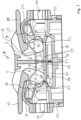
- the conductor connection terminal 9 shown is designed as a connecting terminal. It is constructed essentially symmetrically with respect to a vertical axis of symmetry and has a first spring-loaded clamp connection 1 and a second spring-loaded clamp connection 2 to the left and right of the vertical axis of symmetry.
- the first and second spring-loaded clamp connections 1, 2 are arranged in an insulating housing 4, 5 of the conductor connection terminal 9.
- the insulating housing 4, 5 can, for example, be designed in at least two parts, e.g. from an upper housing part 4 and a base part 5 that can be connected to the upper housing part 4 by locking elements 50.
- the conductor connection terminal 9 can also be designed in such a way that there is a spring-loaded clamp connection on one side and another electrically conductive connection on the other side, e.g. a screw connection. The support plate function is retained.
- the first spring-loaded terminal connection 1 has a loop-shaped, multiply angled first clamping spring 11.
- the first clamping spring 11 has a clamping leg 12 at one end, which serves to clamp an electrical conductor introduced through a first conductor insertion opening 10 against a first clamping point 31 of a busbar 3. The electrical conductor can thus be clamped to a conductor connection side 39 of the busbar 3.
- the clamping leg 12 of the first clamping spring 11 is followed by a spring arch 14, to which a contact leg 15 of the first clamping spring 11 is then connected.
- the first clamping spring 11 extends further in the area of the contact leg 15 into an extended end section 16, in which the material of the first clamping spring 11 is finally bent in a vertical area 17 in the direction of the busbar 3.
- the end section 16 of the contact leg 15 extends beyond the vertical area 17 further downwards through a through opening 30 of the busbar 3 to the end piece 71 of the first clamping spring 11.
- the support plate 8 is located below the busbar 3, i.e. on the side of the busbar 3 facing away from the conductor connection side 39.
- the support plate 8 rests against the busbar 3 with its support surface 80.
- the support plate 8 extends essentially from the first clamping point 31 to the second clamping point 32.
- the end section 16 extends through the recess 82 in the support surface 80, so that the end piece 71 ends below the support surface 80.
- the second clamping spring 21 can, for example, be shaped in the same way as the first clamping spring 11.
- the second spring-force clamping connection 2 has a loop-shaped, multiply angled second clamping spring 21.
- the second clamping spring 21 has a clamping leg 22 at one end, which serves to clamp an electrical conductor introduced through a second conductor insertion opening 20 against a second clamping point 32 of the busbar 3.
- the electrical conductor can be clamped to the conductor connection side 39 of the busbar 3.
- the clamping leg 22 of the second clamping spring 21 is followed by a spring arch 24, to which a contact leg 25 of the second clamping spring 21 is then followed.
- the contact leg 25 rests against an inner wall region 42 of the insulating housing 4, 5 and is at least partially supported there against the forces absorbed by the clamping leg 22.
- the second clamping spring 21 extends further in the region of the contact leg 25 into an extended end section 26, in which the material of the second clamping spring 21 is finally bent in a vertical region 27 in the direction of the busbar 3.
- the end section 26 of the contact leg 25 extends beyond the vertical region 27 further downwards through the through-opening 30 of the busbar 3 and the recess 82 in the support surface 80 as far as the end piece 72 of the first clamping spring 21, so that the end piece 72 ends below the support surface 80.
- the Figure 1 shows the first spring-loaded terminal connection 1 and the second spring-loaded terminal connection 2 in the closed state, ie the first and second actuating levers 19, 29 are in the closed position.
- the clamping leg 12 of the first clamping spring 11 touches the first clamping point 31 of the busbar 3 at the end
- the clamping leg 22 of the second clamping spring 21 touches the second clamping point 32 of the busbar 3 at the end.
- busbar 3 has indentations in the area of its first and second clamping points 31, 32, through which the material of the busbar 3 is slightly protruded upwards, i.e. in the direction of the respective clamping leg 12, 22. This improves the clamping of a connected electrical conductor.
- the busbar 3 is designed as a single piece as a flat, short busbar section.
- the support plate 8 mechanically stabilizes the busbar 3 in this area and also optimizes it in terms of electrical conduction and heat dissipation.
- connection terminal can also be designed as a double connection terminal or a multiple connection terminal.
- double connection terminal there are two clamping points arranged next to each other on each conductor insertion side, and accordingly the arrangement of the first clamping spring on the one hand and the second clamping spring on the other hand is also double.
- first clamping spring on the one hand and the second clamping spring on the other hand is also double.
- two clamping springs 11 and 21 arranged next to each other are connected to each other via a common vertical area 17 and 27 that is continuous in width and are attached to the busbar 3 via this.
- Each vertical area 17, 27 has, e.g.
- the clamping springs 11 and 21 arranged next to each other can be operated independently of each other, ie they are not connected to each other in the other areas, beyond the common vertical areas 17 and 27.
- the end pieces 71, 72 are designed in the shape of a mushroom head. In this way, the respective end pieces 71, 72 also form fixing elements for the positive connection of the support plate 8 to the busbar. This also fixes the clamping springs 11, 21 to the arrangement of the busbar 3 and the support plate 8.
- connection terminal is designed as a multiple connection terminal, there are more than two clamping points arranged next to each other on each conductor insertion side, e.g. 3, 4, 5 or more.
- a common through-opening can be provided in the busbar 3 and the support plate 8 for groups of clamping springs or for all clamping springs for their fixation to the busbar.
- the first clamping spring 11 is supported in the vertical region 17 on the vertical region 27 of the second clamping spring 21, i.e. the clamping springs 11, 21 support each other in the region of their vertical sections 17, 27.
- the vertical region 17 also forms a conductor stop when the first conductor is inserted into the insulating housing.
- the vertical region 27 also forms a conductor stop when the second conductor is inserted into the insulating housing.
- the conductor connection terminal 9 can be designed as a simple conductor connection terminal, in which there is one conductor insertion opening 10, 20 on each side. It can also be designed as a double or multiple terminal. In this case, two or more first conductor insertion openings 10 and two or more second conductor insertion openings 20 are arranged next to each other on each side. For such embodiments, a different design of the respective actuating lever 19, 29 can be advantageous.
- the Figure 5 shows an advantageous embodiment of an actuating lever 6, which can be used as a first or second actuating lever 19, 29, in the event that the conductor connection terminal has only one conductor insertion opening 10, 20 on each side.
- the actuating lever 6 has a manual actuating area 60 (grip area) at which the actuating lever 6 can be actuated by a user.
- the actuating lever 6 also has a bearing axis 61, via which the insulating housing 4, 5 can be mounted.
- the actuating lever 6 is fork-shaped in the area of the bearing axis 61, with a recessed area 65 in the middle, with which the actuating lever 6 can be slipped over the clamping spring located between them.
- the clamping spring then has laterally protruding application areas 13 and 23, respectively, at which the clamping spring can be acted upon via actuating areas 62 of the actuating lever 6.
- a rear contour of the actuating lever 6 has two bearing areas 63, 64 arranged at an angle to one another, via which the actuating lever is supported in the insulating housing and/or on the busbar 3. In the closed actuating position, the actuating lever 6 rests on the bearing area 63, and in the open position on the bearing area 64.
- the bearing axis 61 is accommodated in a groove (not shown) arranged in the upper housing part 4 and aligned essentially perpendicular to the busbar 3, in order to be able to absorb a deflection occurring during the pivoting movement of the actuating lever 19, 29 caused by the bearing areas 63, 64, which slide on the busbar 3 during the pivoting movement of the actuating lever 19, 29.
- the Figure 4 shows a design of an actuating lever 6 which is designed for a conductor connection terminal in which there are two spring-loaded terminal connections arranged next to one another on each side of the housing. Accordingly, the entire actuating lever 6 is designed to be wider and has two adjacent, recessed areas 65 through which the respective clamping springs can be guided. Accordingly, three loading areas 62 are provided. The middle loading area 62 acts simultaneously on the two adjacent clamping springs on one side of the conductor connection terminal 9.
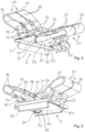
- the conductor connection terminal 9 according to Figure 6 corresponds in its essential structure to the previously established Figures 1 to 3 explained conductor connection terminal 9. Therefore, the differences will be discussed below.
- the Figure 6 shows the first spring-loaded clamp connection 1 with the first actuating lever 19 open, such that the first clamping point 31 is not touched by the clamping leg 12 and any electrical conductor that may have been clamped there beforehand can be removed. It can be seen that the clamping leg 12 of the first clamping spring 11 is then removed from the first clamping point 31.
- the second spring-loaded clamp connection 2 is shown in the closed state, ie the second actuating lever 29 is in the closed position. In this state, the clamping leg 22 of the second clamping spring 21 touches the second clamping point 32 of the busbar 3 at the end.
- the contact leg 15 rests against an inner wall region 41 of the insulating housing 4, 5 and is supported thereat at least in part against the forces absorbed by the clamping leg 12.
- the contact leg 25 rests against an inner wall region 42 of the insulating housing 4, 5 and is supported thereat at least in part against the forces absorbed by the clamping leg 22.
- the end section 16 of the contact leg 15 extends beyond the vertical region 17 further downwards through the through opening 30 of the busbar 3 and the recess 82 of the support plate 8 and is finally suspended in the recess 82, e.g. by an end piece 18 of the end section 16 being further angled and thus engaging behind the recess 82.
- the end section 26 of the contact leg 25 extends beyond the vertical region 27 further downwards through the through opening 30 of the busbar 3 and the recess 82 of the support plate 8 and is finally suspended in the recess 82, e.g. by an end piece 28 of the end section 26 being further angled and thus engaging behind the recess 82.
- the clamping springs 11, 21 may initially, ie before they are attached to the busbar 3, not yet be bent outwards in their respective end pieces 18, 28 as in Figure 1 can be seen. They can initially run essentially in a straight line. After mounting the clamping springs 11, 21 in the through hole 30 of the busbar 3, a further manufacturing step takes place in which the end pieces 18, 28 are bent outwards, ie in the direction of the respective conductor insertion opening 10, 20, and then engage behind the recess 82.
Description
Die Erfindung betrifft eine Leiteranschlussklemme mit wenigstens einem Federkraftklemmanschluss, der wenigstens eine Klemmfeder und wenigstens eine Stromschiene aufweist, wobei ein Klemmschenkel der Klemmfeder gegenüber der Stromschiene vorgespannt ist, so dass ein elektrischer Leiter unter Federkraft zwischen dem Klemmschenkel und einer Leiteranschlussseite der Stromschiene festklemmbar ist.The invention relates to a conductor connection terminal with at least one spring-loaded clamp connection, which has at least one clamping spring and at least one busbar, wherein a clamping leg of the clamping spring is prestressed relative to the busbar, so that an electrical conductor can be clamped under spring force between the clamping leg and a conductor connection side of the busbar.
Eine gattungsgemäße Leiteranschlussklemme ist in Form einer Verbindungsklemme aus der
Der Erfindung liegt die Aufgabe zugrunde, eine Leiteranschlussklemme, z.B. eine Verbindungsklemme, im Hinblick auf die Produktionskosten und die Baugröße weiter zu optimieren.The invention is based on the object of further optimizing a conductor connection terminal, e.g. a connecting terminal, with regard to production costs and size.
Diese Aufgabe wird mit einer Leiteranschlussklemme gemäß Anspruch 1 gelöst. Durch das Hinzufügen des Stützblechs zu einer solchen Leiteranschlussklemme kann insgesamt eine kompaktere, d.h. kleiner bauende Ausführungsform bei zugleich geringen Herstellungskosten realisiert werden. Durch das Stützblech kann eine mechanisch stabile Verbindung der Stromschiene mit der Klemmfeder, bzw. bei einer Verbindungsklemme mit den Klemmfedern, bereitgestellt werden. Die Stromschiene selbst muss hierfür nicht übermäßig mechanisch stabil sein, eine erhöhte Stabilität wird durch das Stützblech bereitgestellt. Durch ein solches Stützblech können somit die für ein sicheres Festklemmen eines elektrischen Leiters erforderlichen hohen Federkräfte aufgenommen werden.This object is achieved with a conductor connection terminal according to claim 1. By adding the support plate to such a conductor connection terminal, a more compact, i.e. smaller, design can be realized overall while at the same time having low manufacturing costs. The support plate can provide a mechanically stable connection of the busbar with the clamping spring, or in the case of a connection terminal with the clamping springs. The busbar itself does not have to be overly mechanically stable for this; increased stability is provided by the support plate. Such a support plate can therefore absorb the high spring forces required for securely clamping an electrical conductor.
Ein weiterer Vorteil besteht darin, dass das Stützblech die Stromschiene bei zusätzlicher elektrischer Belastung sowie bei erhöhter thermischer Belastung unterstützt, z.B. im Falle eines Dauerkurzschlusses. Über das Stützblech kann zusätzlich Wärme abgeleitet werden. Zudem wird die durch die Stromschiene bereitgestellte elektrische Verbindung mittels des Stützblechs weiter verbessert. Eine Leiteranschlussklemme mit einer solchen Konstruktion kann auch mittels eines Automaten montiert werden. Die Leiteranschlussklemme kann zudem mit einem selbsttragenden Kontaktsystem bereitgestellt werden.Another advantage is that the support plate supports the busbar in the event of additional electrical load and increased thermal load, e.g. in the event of a permanent short circuit. Additional heat can be dissipated via the support plate. In addition, the electrical connection provided by the busbar is further improved by means of the support plate. A conductor connection terminal with such a construction can also be assembled using a machine. The conductor connection terminal can also be provided with a self-supporting contact system.
Ein Stützblech im Sinne der Erfindung kann z.B. ein Bauelement sein, das flach und/oder u-förmig oder in anderer geeigneter Form ausgebildet ist und aus elektrisch leitendem Material besteht.A support plate within the meaning of the invention can, for example, be a component that is flat and/or U-shaped or in another suitable form and consists of electrically conductive material.
Gemäß der Erfindung ist vorgesehen, dass das Stützblech auf der der Leiteranschlussseite der Stromschiene abgewandten Seite der Stromschiene angeordnet ist. Auf diese Weise wirkt das Stützblech bei dem Einführen oder Entfernen eines elektrischen Leiters an einer Klemmstelle nicht störend.According to the invention, the support plate is arranged on the side of the busbar facing away from the conductor connection side. In this way, the support plate does not interfere with the insertion or removal of an electrical conductor at a terminal point.
Zwischen dem Stützblech und der Stromschiene können eines oder mehrere andere Bauteile angeordnet sein. Hierbei ist jedoch sicherzustellen, dass eine ausreichende Kraftübertragung zwischen dem Stützblech und der Stromschiene möglich ist, so dass das Stützblech seine Funktion zur Verminderung oder Verhinderung einer durch die Klemmfeder bewirkten Verformung der Stromschiene erfüllen kann. Als andere Bauteile in dem zuvor genannten Sinne eignen sich z.B. unterhalb der Stromschiene, also zwischen Stromschiene und Stützblech, angebrachte leitfähige oder nicht leitfähige Elemente. Leitfähige Elemente können dazu dienen, einen Abzweig und damit eine weitere Anschlussmöglichkeit zu bieten.One or more other components can be arranged between the support plate and the busbar. However, it must be ensured that sufficient force can be transmitted between the support plate and the busbar so that the support plate can fulfil its function of reducing or preventing deformation of the busbar caused by the clamping spring. Other components in the sense mentioned above are, for example, conductive or non-conductive elements mounted below the busbar, i.e. between the busbar and the support plate. Conductive elements can be used to provide a branch and thus another connection option.
Gemäß einer vorteilhaften Weiterbildung der Erfindung ist vorgesehen, dass das Stützblech unmittelbar an der Stromschiene anliegt. Auf diese Weise kann das Stützblech die Stromschiene unmittelbar unterstützen, d.h. es ist eine unmittelbare Kraftübertragung zwischen der Stromschiene und dem Stützblech möglich. Zudem sind auch die Wärmeableitung über das Stützblech sowie die Unterstützung der elektrischen Eigenschaften der Stromschiene optimiert.According to an advantageous development of the invention, the support plate is directly in contact with the busbar. In this way, the support plate can directly support the busbar, i.e. a direct transfer of force between the busbar and the support plate is possible. In addition, the heat dissipation via the support plate and the support of the electrical properties of the busbar are optimized.
Gemäß einer vorteilhaften Weiterbildung der Erfindung ist vorgesehen, dass das Stützblech wenigstens eine im Wesentlichen parallel zur Stromschiene verlaufende Stützfläche und gegebenenfalls wenigstens einen gegenüber der Stützfläche abgewinkelten Verstärkungsabschnitt aufweist, durch den das Flächenträgheitsmoment des Stützblechs zumindest in Längsrichtung der Stromschiene erhöht ist. Auf diese Weise kann das Stützblech bei einfacher Formgebung und Herstellbarkeit eine hohe Stützwirkung bezüglich der Stromschiene ausüben. Das Flächenträgheitsmoment des Stützblechs ist durch den abgewinkelten Verstärkungsabschnitt bzw. die sich durch die Abwinklung ergebende Kante im Vergleich zu einer Ausführungsform des Stützblechs ohne eine solche Abwinklung erhöht. Vorteilhafterweise verläuft der abgewinkelte Verstärkungsabschnitt ebenfalls in Längsrichtung der Stromschiene, wobei leichte Abweichungen von der Längsrichtung der Stromschiene (schräge Anordnung) ebenfalls möglich sind. Das Stützblech kann beispielsweise an beiden Seiten der Stützfläche jeweils einen abgewinkelten Verstärkungsabschnitt aufweisen, so dass das Stützblech im Querschnitt eine U-Form aufweist. Die seitlichen abgewinkelten Verstärkungsabschnitte, z.B. in Form von Stegen (u-Form), sind nicht zwingend notwendig, machen das Stützblech aber stabiler.According to an advantageous development of the invention, it is provided that the support plate has at least one support surface running essentially parallel to the busbar and optionally at least one reinforcement section angled relative to the support surface, by means of which the area moment of inertia of the support plate is increased at least in the longitudinal direction of the busbar. In this way, the support plate can exert a high support effect with respect to the busbar while being easy to shape and manufacture. The area moment of inertia of the support plate is increased by the angled reinforcement section or the edge resulting from the angle compared to an embodiment of the support plate without such an angle. Advantageously, the angled reinforcement section also runs in the longitudinal direction of the busbar, whereby slight deviations from the longitudinal direction of the busbar (oblique arrangement) are also possible. The support plate can, for example, have an angled reinforcement section on both sides of the support surface, so that the support plate has a U-shape in cross section. The lateral angled reinforcement sections, e.g. in the form of webs (u-shape), are not absolutely necessary, but make the support plate more stable.
Gemäß einer vorteilhaften Weiterbildung der Erfindung ist vorgesehen, dass das Stützblech wenigstens eine im Wesentlichen parallel zur Stromschiene verlaufende Stützfläche aufweist, die wenigstens eine Aussparung aufweist, und das Stützblech mittels wenigstens eines durch die Aussparung hindurchragenden Fixierelements an der Stromschiene fixiert ist. Dies erlaubt eine einfache und zuverlässige Fixierung des Stützblechs an der Stromschiene bei zugleich günstiger Kraftübertragung zwischen Stützblech und Stromschiene. Das Stützblech ist auf diese Weise einfach, insbesondere auch automatisiert, an der Stromschiene montierbar. Auf diese Weise kann auch zugleich die Klemmfeder an der aus der Stromschiene und dem Stützblech gebildeten Anordnung befestigt werden.According to an advantageous further training of the The invention provides that the support plate has at least one support surface running essentially parallel to the busbar, which has at least one recess, and the support plate is fixed to the busbar by means of at least one fixing element protruding through the recess. This allows the support plate to be fixed to the busbar in a simple and reliable manner while at the same time ensuring a favorable force transmission between the support plate and the busbar. The support plate can thus be mounted on the busbar in a simple manner, in particular automatically. In this way, the clamping spring can also be attached to the arrangement formed from the busbar and the support plate at the same time.
Gemäß einer vorteilhaften Weiterbildung der Erfindung ist vorgesehen, dass das Stützblech durch das hindurchragende Fixierelement mittels einer formschlüssigen Verbindung an der Stromschiene fixiert ist. Dies erlaubt eine besonders zuverlässige Fixierung des Stützblechs an der Stromschiene, die eine hohe Kraftübertragung zwischen der Stromschiene und dem Stützblech erlaubt.According to an advantageous development of the invention, it is provided that the support plate is fixed to the busbar by means of a positive connection through the protruding fixing element. This allows a particularly reliable fixation of the support plate to the busbar, which allows a high force transmission between the busbar and the support plate.
Das hindurchragende Fixierelement kann zusätzlich durch eine Öffnung in der Stromschiene hindurchragen. Das hindurchragende Fixierelement kann auch als von der Stromschiene abragendes Fixierelement ausgebildet sein.The protruding fixing element can also protrude through an opening in the busbar. The protruding fixing element can also be designed as a fixing element protruding from the busbar.
Gemäß einer vorteilhaften Weiterbildung der Erfindung ist vorgesehen, dass das hindurchragende Fixierelement einstückiger Bestandteil der Klemmfeder ist, insbesondere Bestandteil eines verlängerten Endabschnitts eines Anlageschenkels der Klemmfeder. Dies erlaubt eine einfache und zuverlässige Fixierung des Stützblechs an der Stromschiene bei zugleich günstiger Kraftübertragung auf die Stromschiene. Das Stützblech ist auf diese Weise einfach, insbesondere auch automatisiert, an der Stromschiene montierbar. Zudem muss kein gesondertes Bauteil zur Bereitstellung des Fixierelements eingesetzt werden. Stattdessen kann die Klemmfeder hierzu mitverwendet werden, was zudem die Montage der Leiteranschlussklemme vereinfacht.According to an advantageous development of the invention, the protruding fixing element is an integral part of the clamping spring, in particular part of an extended end section of a contact leg of the clamping spring. This allows the support plate to be fixed to the busbar in a simple and reliable manner while at the same time ensuring a favorable transfer of force to the busbar. The support plate can be mounted on the busbar in this way easily, in particular automatically. In addition, no separate component needs to be used to provide the fixing element. Instead, the clamping spring can be used for this purpose, which also simplifies the installation of the conductor connection terminal.
Gemäß einer vorteilhaften Weiterbildung der Erfindung ist vorgesehen, dass das hindurchragende Fixierelement zumindest in seinem durch die Aussparung hindurchragenden Bereich im Querschnitt eine Pilzkopfform aufweist. Dies erlaubt eine besonders zuverlässige formschlüssige Fixierung des Stützblechs an der Stromschiene bei zugleich einfacher Montierbarkeit der Anordnung. Das hindurchragende Fixierelement bildet durch seine Pilzkopfform einen Pilzkopfzapfen, mit dem eine Pilzkopfverriegelung an dem Stützblech realisiert werden kann. Das hindurchragende Fixierelement kann im Bereich seiner Pilzkopfform z.B. als flaches Blechteil ausgebildet sein. Die Pilzkopfform kann definiert sein durch eine Schmalstelle im Endbereich des Fixierelements (Mae West Form), Ausnehmungen oder andere geeignete Formgebungen zur Realisierung einer formschlüssigen Verbindung.According to an advantageous development of the invention, the protruding fixing element has a mushroom head shape in cross section, at least in the area that protrudes through the recess. This allows a particularly reliable positive locking of the support plate to the busbar while at the same time making the arrangement easy to assemble. The protruding fixing element forms a mushroom head pin with its mushroom head shape, with which a mushroom head lock can be implemented on the support plate. The protruding fixing element can be designed as a flat sheet metal part in the area of its mushroom head shape, for example. The mushroom head shape can be defined by a narrow point in the end area of the fixing element (Mae West shape), recesses or other suitable shapes to implement a positive connection.
Gemäß einer vorteilhaften Weiterbildung der Erfindung ist vorgesehen, dass das Stützblech durch eine Linearbewegung und/oder eine Drehbewegung mittels des Fixierelements an der Stromschiene fixierbar ist. Das Stützblech kann beispielsweise auch durch eine Kombination von Linearbewegung und Drehbewegung mittels des Fixierelements an der Stromschiene fixiert werden. Solche Bewegungsvorgänge sind sowohl von einem Menschen als auch von einer automatisierten Fertigungseinrichtung einfach und schnell ausführbar.According to an advantageous development of the invention, it is provided that the support plate can be fixed to the busbar by a linear movement and/or a rotary movement using the fixing element. The support plate can also be fixed to the busbar by a combination of linear movement and rotary movement using the fixing element. Such movement processes can be carried out quickly and easily by both a person and an automated production facility.
Gemäß einer vorteilhaften Weiterbildung der Erfindung ist vorgesehen, dass die Leiteranschlussklemme als Verbindungsklemme zum Verbinden wenigstens zweier elektrischer Leiter miteinander ausgebildet ist, mit folgenden Merkmalen:
- a) die Verbindungsklemme weist ein Isolierstoffgehäuse mit wenigstens einer ersten und einer zweiten Leitereinführungsöffnung auf,
- b) die erste und die zweite Leitereinführungsöffnung sind an einander gegenüberliegenden Gehäuseseiten des Isolierstoffgehäuses angeordnet,
- c) in dem Isolierstoffgehäuse sind ein erster Federkraftklemmanschluss zur elektrischen Kontaktierung eines durch die erste Leitereinführungsöffnung eingeführten ersten elektrischen Leiters und einen zweiter Federkraftklemmanschluss zur elektrischen Kontaktierung eines durch die zweite Leitereinführungsöffnung eingeführten zweiten elektrischen Leiters angeordnet,
- d) der erste Federkraftklemmanschluss ist mit dem zweiten Federkraftklemmenanschluss über dieselbe durchgehende Stromschiene elektrisch verbunden.
- a) the connecting terminal has an insulating housing with at least a first and a second conductor insertion opening,
- b) the first and second conductor insertion openings are arranged on opposite sides of the insulating housing,
- c) a first spring-loaded terminal connection for electrically contacting a first electrical conductor introduced through the first conductor introduction opening and a second spring-loaded terminal connection for electrically contacting a second electrical conductor introduced through the second conductor introduction opening are arranged in the insulating housing,
- d) the first spring-loaded terminal connection is electrically connected to the second spring-loaded terminal connection via the same continuous busbar.
Auf diese Weise lassen sich die zuvor erläuterten Vorteile auch bei einer Verbindungsklemme realisieren. Gerade bei Verbindungsklemme ist ein wesentlicher Vorteil in einer besonders kleinbauenden Anordnung und einer kostengünstigen Herstellungsweise zu sehen.In this way, the previously explained advantages can also be achieved with a connecting terminal. A key advantage of connecting terminals in particular is the particularly small design and cost-effective manufacturing process.
Bei der Verbindungsklemme kann somit der erste Federkraftklemmanschluss wie der eingangs erwähnte Federkraftklemmanschluss der Leiteranschlussklemme ausgebildet sein, zudem kann der zweite Federkraftklemmanschluss wie der eingangs erwähnte Federkraftklemmanschluss der Leiteranschlussklemme ausgebildet sein. Die eingangs erwähnte Stromschiene der Leiteranschlussklemme ist bei der Verbindungsklemme dann eine einzige durchgehende Stromschiene, die somit die beiden Federkraftklemmanschlüsse miteinander elektrisch und in gewissem Umfang auch mechanisch verbindet.In the connection terminal, the first spring-loaded terminal connection can thus be designed like the spring-loaded terminal connection of the conductor connection terminal mentioned at the beginning, and the second spring-loaded terminal connection can also be designed like the spring-loaded terminal connection of the conductor connection terminal mentioned at the beginning. The busbar of the conductor connection terminal mentioned at the beginning is then a single continuous busbar in the connection terminal, which thus connects the two spring-loaded terminal connections to one another electrically and, to a certain extent, mechanically.
Hierzu kann der erste Federkraftklemmanschluss eine erste Klemmfeder aufweisen, die einen Klemmschenkel zum Klemmen des ersten elektrischen Leiters gegen eine erste Klemmstelle der Stromschiene und einen Anlageschenkel zum Abstützen der Klemmfeder aufweist. Der zweite Federkraftklemmanschluss kann eine zweite Klemmfeder aufweisen, die einen Klemmschenkel zum Klemmen des zweiten elektrischen Leiters gegen eine zweite Klemmstelle der Stromschiene und einen Anlageschenkel zum Abstützen der zweiten Klemmfeder aufweist.For this purpose, the first spring-loaded terminal connection can have a first clamping spring, which has a clamping leg for clamping the first electrical conductor against a first clamping point of the busbar and a contact leg for supporting the clamping spring. The second spring-loaded terminal connection may have a second clamping spring having a clamping leg for clamping the second electrical conductor against a second clamping point of the busbar and a contact leg for supporting the second clamping spring.
Gemäß einer vorteilhaften Weiterbildung der Erfindung ist vorgesehen, dass die Stromschiene wenigstens eine Durchgangsöffnung aufweist, die zwischen der ersten und der zweiten Klemmstelle angeordnet ist, wobei ein verlängerter Endabschnitt des Anlageschenkels der ersten und/oder der zweiten Klemmfeder durch die Durchgangsöffnung der Stromschiene geführt ist und als Fixierelement an dem Stützblech befestigt ist. Die Durchgangsöffnung der Stromschiene kann insbesondere zumindest im Wesentlichen fluchtend mit der Aussparung des Stützblechs angeordnet sein, so dass ein und dasselbe Fixierelement durch die Durchgangsöffnung der Stromschiene und die Aussparung des Stützblechs geführt sein kann. Im Fall einer Verbindungsklemme kann sowohl die erste als auch die zweite Klemmfeder ein Fixierelement als einstückigen Bestandteil der jeweiligen Klemmfeder aufweisen, insbesondere in Form eines verlängerten Endabschnitts eines Anlageschenkels der Klemmfeder.According to an advantageous development of the invention, it is provided that the busbar has at least one through-opening which is arranged between the first and the second clamping point, wherein an extended end section of the contact leg of the first and/or the second clamping spring is guided through the through-opening of the busbar and is fastened to the support plate as a fixing element. The through-opening of the busbar can in particular be arranged at least substantially flush with the recess of the support plate, so that one and the same fixing element can be guided through the through-opening of the busbar and the recess of the support plate. In the case of a connecting terminal, both the first and the second clamping spring can have a fixing element as an integral component of the respective clamping spring, in particular in the form of an extended end section of a contact leg of the clamping spring.
Gemäß einer vorteilhaften Weiterbildung der Erfindung ist vorgesehen, dass sich das Stützblech entlang der Stromschiene von dem ersten Federkraftklemmanschluss zu dem zweiten Federkraftklemmenanschluss erstreckt. Auf diese Weise kann das Stützblech, vergleichbar wie die Stromschiene, als durchgehendes Bauteil ausgebildet sein, das seine Stützwirkung sowohl im Bereich des ersten als auch im Bereich des zweiten Federkraftklemmanschlusses ausübt.According to an advantageous development of the invention, it is provided that the support plate extends along the busbar from the first spring-loaded terminal connection to the second spring-loaded terminal connection. In this way, the support plate, comparable to the busbar, can be designed as a continuous component that exerts its supporting effect both in the area of the first and in the area of the second spring-loaded terminal connection.
Gemäß einer vorteilhaften Weiterbildung der Erfindung ist vorgesehen, dass die erste und/oder die zweite Klemmfeder schlaufenförmig ausgebildet ist, wobei der jeweilige Anlageschenkel in einem verlängerten Endabschnitt der jeweiligen Klemmfeder in Richtung zur Stromschiene abgebogen ist. Auf diese Weise kann die Klemmfeder in günstiger Weise einstückig mit dem Fixierelement zur Fixierung des Stützblechs an der Stromschiene ausgebildet sein.According to an advantageous development of the invention, it is provided that the first and/or the second clamping spring is designed in a loop shape, wherein the respective contact leg is bent in an extended end section of the respective clamping spring in the direction of the busbar. In this way, the clamping spring can be advantageously designed in one piece with the fixing element for fixing the support plate to the busbar.
Gemäß einer vorteilhaften Weiterbildung der Erfindung ist vorgesehen, dass die erste Klemmfeder die zweite Klemmfeder im Bereich ihrer jeweiligen Anlageschenkel berührt. Dies hat den Vorteil, dass sich die erste und die zweite Klemmfeder gegenseitig abstützen können, d.h. die eine Klemmfeder kann Druckkräfte der anderen Klemmfeder absorbieren. Auch hierdurch kann eine Materialeinsparung und ein kompaktes Design der Verbindungsklemme realisiert werden. Zudem wird die Belastung des Isolierstoffgehäuses durch Federkräfte minimiert, so dass das Isolierstoffgehäuse ebenfalls vereinfacht werden kann.According to an advantageous development of the invention, the first clamping spring touches the second clamping spring in the area of their respective contact legs. This has the advantage that the first and second clamping springs can support each other, i.e. one clamping spring can absorb pressure forces from the other clamping spring. This also allows material savings and a compact design of the connection terminal to be achieved. In addition, the load on the insulating housing caused by spring forces is minimized, so that the insulating housing can also be simplified.
Die Erfindung wird nachfolgend anhand von Ausführungsbeispielen unter Verwendung von Zeichnungen näher erläutert. Es zeigen:
- Figur 1
- - eine Leiteranschlussklemme in seitlicher Schnittdarstellung und
Figuren - - den Kontakteinsatz der Leiteranschlussklemme gemäß
Figur 1 in unterschiedlichen perspektivischen Ansichten und Figuren 4, 5- - Betätigungshebel in perspektivischen Ansichten und
Figur 6- - eine weitere Ausführungsform einer Leiteranschlussklemme in seitlicher Schnittansicht.
- Figure 1
- - a conductor connection terminal in lateral section and
- Figures 2, 3
- - the contact insert of the conductor connection terminal according to
Figure 1 in different perspective views and - Figures 4, 5
- - Operating lever in perspective views and
- Figure 6
- - another embodiment of a conductor connection terminal in a side sectional view.
In den Figuren werden gleiche Bezugszeichen für einander entsprechende Elemente verwendet, die folgende Zuordnung haben:
- 1
- - erster Federkraftklemmanschluss
- 2
- - zweiter Federkraftklemmanschluss
- 3
- - Stromschiene
- 4
- - Gehäuseoberteil
- 5
- - Bodenteil
- 6
- - Betätigungshebel
- 8
- - Stützblech
- 9
- - Leiteranschlussklemme
- 10
- - erste Leitereinführungsöffnung
- 11
- - erste Klemmfeder
- 12
- - Klemmschenkel
- 13
- - Beaufschlagungsbereich
- 14
- - Federbogen
- 15
- - Anlageschenkel
- 16
- - Endabschnitt
- 17
- - Vertikalbereich
- 18
- - Endstück des Endabschnitts
- 19
- - Betätigungshebel
- 20
- - zweite Leitereinführungsöffnung
- 21
- - zweite Klemmfeder
- 22
- - Klemmschenkel
- 23
- - Beaufschlagungsbereich
- 24
- - Federbogen
- 25
- - Anlageschenkel
- 26
- - Endabschnitt
- 27
- - Vertikalbereich
- 28
- - Endstück des Endabschnitts
- 29
- - Betätigungshebel
- 30
- - Durchgangsöffnung
- 31
- - erste Klemmstelle
- 32
- - zweite Klemmstelle
- 39
- - Leiteranschlussseite der Stromschiene
- 41
- - innerer Wandbereich
- 42
- - innerer Wandbereich
- 50
- - Rastelemente
- 60
- - manueller Betätigungsbereich
- 61
- - Lagerungsachse
- 62
- - Betätigungsbereiche des Betätigungshebels
- 63, 64
- - Lagerbereiche
- 65
- - ausgesparter Bereich
- 71, 72
- - Endstücke
- 73, 74
- - herausgestellte Materialbereiche
- 80
- - Stützfläche
- 81
- - Verstärkungsabschnitt
- 82
- - Aussparung
- 1
- - first spring clamp connection
- 2
- - second spring clamp connection
- 3
- - Busbar
- 4
- - Housing top
- 5
- - Base part
- 6
- - Operating lever
- 8th
- - Support plate
- 9
- - Conductor connection terminal
- 10
- - first conductor entry opening
- 11
- - first clamping spring
- 12
- - Clamping leg
- 13
- - Exposure area
- 14
- - Spring bow
- 15
- - Investment leg
- 16
- - End section
- 17
- - Vertical range
- 18
- - End piece of the end section
- 19
- - Operating lever
- 20
- - second conductor entry opening
- 21
- - second clamping spring
- 22
- - Clamping leg
- 23
- - Exposure area
- 24
- - Spring bow
- 25
- - Investment leg
- 26
- - End section
- 27
- - Vertical range
- 28
- - End piece of the end section
- 29
- - Operating lever
- 30
- - Passage opening
- 31
- - first clamping point
- 32
- - second clamping point
- 39
- - Conductor connection side of the busbar
- 41
- - inner wall area
- 42
- - inner wall area
- 50
- - Locking elements
- 60
- - manual operating area
- 61
- - Bearing axis
- 62
- - Operating range of the operating lever
- 63, 64
- - Storage areas
- 65
- - recessed area
- 71, 72
- - End pieces
- 73, 74
- - highlighted material areas
- 80
- - Support surface
- 81
- - Reinforcement section
- 82
- - Recess
Die in
Der erste Federkraftklemmanschluss 1 weist eine schlaufenförmig mehrfach abgewinkelte erste Klemmfeder 11 auf. Die erste Klemmfeder 11 weist an einem Ende einen Klemmschenkel 12 auf, der zum Klemmen eines durch eine erste Leitereinführungsöffnung 10 eingeführten elektrischen Leiters gegen eine erste Klemmstelle 31 einer Stromschiene 3 dient. Der elektrische Leiter ist auf diese Weise an einer Leiteranschlussseite 39 der Stromschiene 3 festklemmbar. Im Bereich des Klemmschenkels 12 ist ein Beaufschlagungsbereich 13 der ersten Klemmfeder 11 vorhanden, an dem der Klemmschenkel 12 zum Öffnen und Schließen des ersten Federkraftklemmanschlusses 1 über einen Betätigungshebel 19 betätigt werden kann.The first spring-loaded terminal connection 1 has a loop-shaped, multiply angled first clamping
An den Klemmschenkel 12 der ersten Klemmfeder 11 schließt sich ein Federbogen 14 an, an den sich dann ein Anlageschenkel 15 der ersten Klemmfeder 11 anschließt. Die erste Klemmfeder 11 erstreckt sich im Bereich des Anlageschenkels 15 weiter in einen verlängerten Endabschnitt 16, in dem das Material der ersten Klemmfeder 11 schließlich in einem Vertikalbereich 17 in Richtung zur Stromschiene 3 abgebogen ist. Der Endabschnitt 16 des Anlageschenkels 15 erstreckt sich über den Vertikalbereich 17 hinaus weiter nach unten durch eine Durchgangsöffnung 30 der Stromschiene 3 bis hin zu dem Endstück 71 der ersten Klemmfeder 11.The clamping
Unterhalb der Stromschiene 3, d.h. auf der der Leiteranschlussseite 39 abgewandten Seite der Stromschiene 3, befindet sich das Stützblech 8. Das Stützblech 8 liegt mit seiner Stützfläche 80 an der Stromschiene 3 an. Wie man erkennt, erstreckt sich das Stützblech 8 im Wesentlichen von der ersten Klemmstelle 31 zur zweiten Klemmstelle 32. Der Endabschnitt 16 erstreckt sich durch die Aussparung 82 in der Stützfläche 80, so dass das Endstück 71 unterhalb der Stützfläche 80 endet.The
Die zweite Klemmfeder 21 kann beispielsweise ebenso geformt sein wie die erste Klemmfeder 11. Hierfür ist vorgesehen, dass der zweite Federkraftklemmanschluss 2 eine schlaufenförmig mehrfach abgewinkelte zweite Klemmfeder 21 auf weist. Die zweite Klemmfeder 21 weist an einem Ende einen Klemmschenkel 22 auf, der zum Klemmen eines durch eine zweite Leitereinführungsöffnung 20 eingeführten elektrischen Leiters gegen eine zweite Klemmstelle 32 der Stromschiene 3 dient. Auch hier ist der elektrische Leiter an der Leiteranschlussseite 39 der Stromschiene 3 festklemmbar. Im Bereich des Klemmschenkels 22 ist ein Beaufschlagungsbereich 23 der zweiten Klemmfeder 21 vorhanden, an dem der Klemmschenkel 22 zum Öffnen und Schließen des zweiten Federkraftklemmanschlusses 2 über einen Betätigungshebel 29 betätigt werden kann.The
An den Klemmschenkel 22 der zweiten Klemmfeder 21 schließt sich ein Federbogen 24 an, an den sich dann ein Anlageschenkel 25 der zweiten Klemmfeder 21 anschließt. Der Anlageschenkel 25 liegt an einem inneren Wandbereich 42 des Isolierstoffgehäuses 4, 5 an und wird daran zumindest zum Teil gegenüber den vom Klemmschenkel 22 aufgenommenen Kräften abgestützt. Die zweite Klemmfeder 21 erstreckt sich im Bereich des Anlageschenkels 25 weiter in einen verlängerten Endabschnitt 26, in dem das Material der zweiten Klemmfeder 21 schließlich in einem Vertikalbereich 27 in Richtung zur Stromschiene 3 abgebogen ist. Der Endabschnitt 26 des Anlageschenkels 25 erstreckt sich über den Vertikalbereich 27 hinaus weiter nach unten durch die Durchgangsöffnung 30 der Stromschiene 3 und die Aussparung 82 in der Stützfläche 80 bis hin zu dem Endstück 72 der ersten Klemmfeder 21, so dass das Endstück 72 unterhalb der Stützfläche 80 endet.The clamping
Die
Wie in der
Erkennbar ist ferner, dass die Stromschiene 3 im Bereich ihrer ersten und zweiten Klemmstellen 31, 32 Einprägungen aufweist, durch die das Material der Stromschiene 3 nach oben hin, d.h. in Richtung zum jeweiligen Klemmschenkel 12, 22, etwas herausgestellt ist. Hierdurch wird die Klemmung eines angeschlossenen elektrischen Leiters verbessert.It can also be seen that the
Die Stromschiene 3 ist einstückig als flachbauendes kurzes Stromschienenstück ausgebildet. Durch das Stützblech 8 wird die Stromschiene 3 in diesem Bereich mechanisch stabilisiert und zudem hinsichtlich der elektrischen Leitung und der Wärmeabfuhr optimiert.The
Die beschriebene Verbindungsklemme kann auch Doppelverbindungsklemme oder Mehrfachverbindungsklemme ausgebildet sein. Bei Ausführung als Doppelverbindungsklemme sind an jeder Leitereinführseite zwei nebeneinander angeordnete Klemmstellen vorhanden, dementsprechend ist auch die Anordnung der ersten Klemmfeder einerseits und der zweiten Klemmfeder andererseits doppelt vorhanden. Dies ist in den Darstellungen der
Wie man in der
Wenn die Verbindungsklemme als Mehrfachverbindungsklemme ausgebildet ist, sind mehr als zwei nebeneinander angeordnete Klemmstellen an jeder Leitereinführseite vorhanden, z. B. 3, 4, 5 oder mehr. Hierbei kann jeweils für Gruppen von Klemmfedern oder für sämtliche Klemmfedern zu deren Fixierung an der Stromschiene eine gemeinsame Durchgangsöffnung in der Stromschiene 3 und dem Stützblech 8 vorhanden sein.If the connection terminal is designed as a multiple connection terminal, there are more than two clamping points arranged next to each other on each conductor insertion side, e.g. 3, 4, 5 or more. In this case, a common through-opening can be provided in the
Die Montage der Leiteranschlussklemme 9 kann z.B. wie folgt durchgeführt werden:
- Zunächst werden die
Klemmfedern den Figuren 2 und 3 erkennbaren Anordnung zueinander ausgerichtet, d.h. derart, dass dieKlemmfedern über ihre Vertikalbereiche - Dann kann die
Stromschiene 3mit ihrer Durchgangsöffnung 30sowie das Stützblech 8mit seiner Aussparung 82 über dieEndstücke Klemmfedern - Dies erfolgt beispielsweise derart, dass die Stromschiene und das Stützblech zunächst in einer um 90 Grad gedrehten Lage über die
Endstücke Figur 3förmigen Endstücke mit der Stromschiene 3und dem Stützblech 8 erfolgen kann. Hierfür ist es vorteilhaft, wenn die Durchgangsöffnung 30 und dieAussparung 82 schmal und schlitzfömig ausgebildet sind. Alternativ kann dieDurchgangsöffnung 30 sowie die Aussparung 82 in Draufsicht eine T-Form aufweisen, d.h. eine Aussparung mit einem breiten und einem sich daran anschließenden schmalen Bereich. In diesem Fall können dieStromschiene 3und das Stützblech 8 ohne Drehbewegung über dieEndstücke Endstücke Verschiebebewegung die Stromschiene 3und das Stützblech 8 derart verschoben werden, dass dieEndstücke Die Betätigungshebel Anlageschenkel Stromschiene 3 bewegt werden;Die Klemmfedern - Ggf. genutzte Dorne werden zurückgezogen;
- Die nun vormontierte
Einheit mit Stromschiene 3,Klemmfedern das auf Bodenteil 5 gesetzt; - Das Gehäuseoberteil 4 wird übergestülpt;
Die Betätigungshebel
- First, the clamping springs 11, 21 are inserted into the
Figures 2 and 3 recognizable arrangement to each other, ie such that the clamping springs 11, 21 lie back to back against each other via theirvertical regions - Then the
busbar 3 with its through-opening 30 and thesupport plate 8 with itsrecess 82 can be guided over theend pieces - This is done, for example, in such a way that the busbar and the support plate are first guided over the
end pieces Figure 3 recognizable position, so that the clamping springs 11, 21 can be locked to thebusbar 3 and thesupport plate 8 via the mushroom-head-shapedend pieces opening 30 and therecess 82 are narrow and slot-shaped. Alternatively, the through-opening 30 and therecess 82 can have a T-shape in plan view, ie a recess with a wide and an adjoining narrow area. In this case, thebusbar 3 and thesupport plate 8 can be guided over theend pieces end pieces busbar 3 and thesupport plate 8 are displaced by a sliding movement such that theend pieces - The operating levers 19, 29 can be moved over the
contact legs busbar 3 in a position corresponding to the closed position; - The clamping springs 11, 21 are moved into the (completely) open position by pivoting the operating levers 19, 29;
- Any mandrels used are withdrawn;
- The now pre-assembled unit with
busbar 3, clamping springs 11, 21 andoperating levers 19, 29 (in open position) is placed on thebase part 5; - The upper housing part 4 is put over it;
- The operating levers 19, 29 are pivoted into the closed position.
Die erste Klemmfeder 11 ist dabei im Vertikalbereich 17 an dem Vertikalbereich 27 der zweiten Klemmfeder 21 abgestützt, d.h., die Klemmfedern 11, 21 stützen sich im Bereich ihrer Vertikalabschnitte 17, 27 gegenseitig ab. Der Vertikalbereich 17 bildet zudem einen Leiteranschlag beim Einführen des ersten Leiters in das Isolierstoffgehäuse. Der Vertikalbereich 27 bildet zudem einen Leiteranschlag beim Einführen des zweiten Leiters in das Isolierstoffgehäuse.The
Die Leiteranschlussklemme 9 kann als einfache Leiteranschlussklemme ausgebildet sein, bei der jeweils eine Leitereinführungsöffnung 10, 20 auf jeder Seite vorhanden ist. Sie kann auch als Zweifach- oder Mehrfachklemme ausgebildet sein. In diesem Fall sind auf jeder Seite zwei oder mehr erste Leitereinführungsöffnungen 10 und zwei oder mehr zweite Leitereinführungsöffnungen 20 jeweils nebeneinander angeordnet vorhanden. Für solche Ausführungsformen kann eine andere Ausgestaltung des jeweiligen Betätigungshebels 19, 29 vorteilhaft sein.The
Die
Die
Die Leiteranschlussklemme 9 gemäß
Die
Der Anlageschenkel 15 liegt an einem inneren Wandbereich 41 des Isolierstoffgehäuses 4, 5 an und wird daran zumindest zum Teil gegenüber den vom Klemmschenkel 12 aufgenommenen Kräften abgestützt. Der Anlageschenkel 25 liegt an einem inneren Wandbereich 42 des Isolierstoffgehäuses 4, 5 an und wird daran zumindest zum Teil gegenüber den vom Klemmschenkel 22 aufgenommenen Kräften abgestützt.The
Der Endabschnitt 16 des Anlageschenkels 15 erstreckt sich über den Vertikalbereich 17 hinaus weiter nach unten durch die Durchgangsöffnung 30 der Stromschiene 3 und die Aussparung 82 des Stützblechs 8 und ist schließlich in der Aussparung 82 eingehängt, z.B. indem ein Endstück 18 des Endabschnitts 16 weiter abgewinkelt wird und damit die Aussparung 82 hintergreift. Der Endabschnitt 26 des Anlageschenkels 25 erstreckt sich über den Vertikalbereich 27 hinaus weiter nach unten durch die Durchgangsöffnung 30 der Stromschiene 3 und die Aussparung 82 des Stützblechs 8 und ist schließlich in der Aussparung 82 eingehängt, z.B. indem ein Endstück 28 des Endabschnitts 26 weiter abgewinkelt wird und damit die Aussparung 82 hintergreift.The
Die Klemmfedern 11, 21 können zunächst, d.h. bevor sie an der Stromschiene 3 befestigt sind, in ihren jeweiligen Endstücken 18, 28 noch nicht derart nach außen gebogen sein wie in
Claims (13)
- Conductor connection terminal (9) with at least one spring force clamping connection (1, 2), which has at least one clamping spring (11, 21) and at least one current bar (3), wherein a clamping limb (12, 22) of the clamping spring (11, 21) is pretensioned relative to the current bar (3), such that an electrical conductor is connectable under spring force between the clamping limb (12, 21) and a conductor connection side (39) of the current bar (3), characterized in that the current bar (3) can be deformed by the clamping spring (11, 21), the conductor connection terminal (9) having as a further component at least one support plate (8) by which the current bar (3) is supported against deformation of the current bar (3) caused by the clamping spring (11, 21), wherein the support plate (8) is arranged on the side of the current bar (3) facing away from the conductor connection side (39) of the current bar (3).
- Conductor connection terminal according to one of the preceding claims, characterized in that the support plate (8) lies directly against the current bar (3).
- Conductor connection terminal according to one of the preceding claims, characterized in that the support plate (8) has at least one support surface (80) extending substantially parallel to the current rail and optionally at least one reinforcing section (81) angled relative to the support surface (80), by which the moment of inertia of the support plate (8) is increased at least in the longitudinal direction of the current bar (3).
- Conductor connection terminal according to one of the preceding claims, characterized in that the support plate (8) has at least one support surface (80) running essentially parallel to the current bar, which has at least one recess (82), and the support plate (8) is fixed to the current bar (3) by means of at least one fixing element (18, 28, 71, 72) projecting through the recess (82).
- Conductor connection terminal according to the preceding claim, characterized in that the support plate (8) is fixed to the current bar (3) by means of a positive connection through the fixing element (18, 28, 71, 72) projecting through the recess (82).
- Conductor connection terminal according to one of claims 4 to 5, characterized in that the fixing element (18, 28, 71, 72) projecting through is an integral component of the clamping spring (11, 21), in particular a component of an extended end section (16, 26) of a contact leg (15, 25) of the clamping spring (11, 21).
- Conductor connection terminal according to one of claims 4 to 6, characterized in that the fixing element (18, 28, 71, 72) projecting through has a mushroom head shape in cross section at least in its region projecting through the recess (82).
- Conductor connection terminal according to one of claims 4 to 7, characterized in that the support plate (8) can be fixed to the current bar (3) by a linear movement and/or a rotary movement by means of the fixing element (18, 28, 71, 72).
- Conductor connection terminal according to one of the preceding claims, the conductor connecting terminal (9) being designed as a connecting terminal for connecting at least two electrical conductors to one another, having the following features:a) the connecting terminal has an insulating material housing (4, 5) with at least one first and one second conductor insertion opening (10, 20),b) the first and second conductor insertion openings (10, 20) are arranged on opposite sides of the insulating material housing (4, 5),c) in the insulating material housing (4, 5) there are arranged a first spring force clamping terminal (1) for electrically contacting a first electrical conductor inserted through the first conductor insertion opening (10) and a second spring force clamping terminal (2) for electrically contacting a second electrical conductor inserted through the second conductor insertion opening (20),d) the first spring force terminal connection (1) is electrically connected to the second spring force terminal connection (2) via the same current bar (3).
- Conductor connection terminal according to the preceding claim, characterized in that the current bar (3) has at least one through-opening (30) arranged between the first and second clamping points (31, 32), wherein an extended end portion (16, 26) of the contact leg (15, 25) of the first and/or the second clamping spring (11, 21) is guided through the through-opening (30) of the current bar (3) and is fastened to the support plate (8) as a fixing element (18, 28, 71, 72).
- Conductor connection terminal according to one of claims 9 to 10, characterized in that the support plate (8) extends along the current bar (3) from the first spring force terminal connection (1) to the second spring force terminal connection (2).
- Conductor connection terminal according to one of the claims 9 to 10, characterized in that the first and/or the second clamping spring (11, 21) is formed in the shape of a sleeve, wherein the respective contact limb (15, 25) is bent in the direction of the current bar (3) in an extended end section (16, 26) of the respective clamping spring (11, 21).
- Conductor connection terminal according to one of claims 9 to 11, characterized in that the first clamping spring (11) touches the second clamping spring (21) in the area of its respective contact legs (15, 25).
Priority Applications (1)
| Application Number | Priority Date | Filing Date | Title |
|---|---|---|---|
| PL18192960T PL3454422T3 (en) | 2017-09-08 | 2018-09-06 | Cable connection terminal |
Applications Claiming Priority (1)
| Application Number | Priority Date | Filing Date | Title |
|---|---|---|---|
| DE202017105467.5U DE202017105467U1 (en) | 2017-09-08 | 2017-09-08 | Conductor terminal |
Publications (3)
| Publication Number | Publication Date |
|---|---|
| EP3454422A1 EP3454422A1 (en) | 2019-03-13 |
| EP3454422B1 EP3454422B1 (en) | 2021-03-17 |
| EP3454422B2 true EP3454422B2 (en) | 2024-04-17 |
Family
ID=63524157
Family Applications (1)
| Application Number | Title | Priority Date | Filing Date |
|---|---|---|---|
| EP18192960.5A Active EP3454422B2 (en) | 2017-09-08 | 2018-09-06 | Cable connection terminal |
Country Status (3)
| Country | Link |
|---|---|
| EP (1) | EP3454422B2 (en) |
| DE (1) | DE202017105467U1 (en) |
| PL (1) | PL3454422T3 (en) |
Families Citing this family (7)
| Publication number | Priority date | Publication date | Assignee | Title |
|---|---|---|---|---|
| DE102019108291A1 (en) * | 2019-03-29 | 2020-10-01 | Wago Verwaltungsgesellschaft Mbh | Conductor connection terminal |
| DE102019116930B4 (en) * | 2019-06-24 | 2023-11-16 | WAGO Verwaltungsgesellschaft mit beschränkter Haftung | Electrical connection terminal |
| DE102019117302A1 (en) * | 2019-06-27 | 2020-12-31 | Phoenix Contact Gmbh & Co. Kg | Terminal arrangement for connecting at least one electrical conductor |
| DE102019120302B4 (en) * | 2019-07-26 | 2022-11-24 | Wago Verwaltungsgesellschaft Mbh | Conductor terminal, clamping spring of a conductor terminal and arrangement of at least two clamping springs |
| DE102019132008A1 (en) * | 2019-11-26 | 2021-05-27 | Phoenix Contact Gmbh & Co. Kg | Terminal as well as electronic device |
| DE202020100089U1 (en) * | 2020-01-09 | 2021-04-12 | Wago Verwaltungsgesellschaft Mbh | Conductor connection terminal |
| DE102020104080C5 (en) * | 2020-02-17 | 2022-05-05 | WAGO Verwaltungsgesellschaft mit beschränkter Haftung | Conductor terminal and method of assembling a conductor terminal |
Citations (5)
| Publication number | Priority date | Publication date | Assignee | Title |
|---|---|---|---|---|
| DE202009002324U1 (en) † | 2009-02-18 | 2010-07-29 | Weidmüller Interface GmbH & Co. KG | Terminal for connecting conductor ends |
| DE202010009666U1 (en) † | 2010-06-30 | 2011-11-29 | Weidmüller Interface GmbH & Co. KG | Miniature spring clamp |
| DE102013101411A1 (en) † | 2013-02-13 | 2014-08-14 | Wago Verwaltungsgesellschaft Mbh | Spring terminal connection and conductor terminal |
| DE102014119421A1 (en) † | 2014-12-22 | 2016-06-23 | Wago Verwaltungsgesellschaft Mbh | Connection terminal and method for mounting a connection terminal |
| EP3125372A1 (en) † | 2011-12-14 | 2017-02-01 | Wago Verwaltungsgesellschaft mbH | Connection terminal |
Family Cites Families (4)
| Publication number | Priority date | Publication date | Assignee | Title |
|---|---|---|---|---|
| DE10355195B4 (en) * | 2003-11-26 | 2007-03-15 | Wieland Electric Gmbh | wire connection |
| DE102010025930B4 (en) * | 2010-07-02 | 2019-10-17 | Phoenix Contact Gmbh & Co. Kg | terminal |
| DE102013101830B4 (en) * | 2013-01-08 | 2017-12-28 | Wago Verwaltungsgesellschaft Mbh | Electrical connection terminal and method for its assembly |
| DE102015119247A1 (en) | 2015-11-09 | 2017-05-11 | Wago Verwaltungsgesellschaft Mbh | connecting terminal |
-
2017
- 2017-09-08 DE DE202017105467.5U patent/DE202017105467U1/en active Active
-
2018
- 2018-09-06 EP EP18192960.5A patent/EP3454422B2/en active Active
- 2018-09-06 PL PL18192960T patent/PL3454422T3/en unknown
Patent Citations (5)
| Publication number | Priority date | Publication date | Assignee | Title |
|---|---|---|---|---|
| DE202009002324U1 (en) † | 2009-02-18 | 2010-07-29 | Weidmüller Interface GmbH & Co. KG | Terminal for connecting conductor ends |
| DE202010009666U1 (en) † | 2010-06-30 | 2011-11-29 | Weidmüller Interface GmbH & Co. KG | Miniature spring clamp |
| EP3125372A1 (en) † | 2011-12-14 | 2017-02-01 | Wago Verwaltungsgesellschaft mbH | Connection terminal |
| DE102013101411A1 (en) † | 2013-02-13 | 2014-08-14 | Wago Verwaltungsgesellschaft Mbh | Spring terminal connection and conductor terminal |
| DE102014119421A1 (en) † | 2014-12-22 | 2016-06-23 | Wago Verwaltungsgesellschaft Mbh | Connection terminal and method for mounting a connection terminal |
Also Published As
| Publication number | Publication date |
|---|---|
| PL3454422T3 (en) | 2021-10-04 |
| EP3454422A1 (en) | 2019-03-13 |
| DE202017105467U1 (en) | 2018-12-12 |
| EP3454422B1 (en) | 2021-03-17 |
Similar Documents
| Publication | Publication Date | Title |
|---|---|---|
| EP3454422B2 (en) | Cable connection terminal | |
| EP3627625B1 (en) | Connecting terminal | |
| EP2862236B1 (en) | Electrical connection terminal | |
| EP3324490B1 (en) | Spring clamp contact for connecting an electrical conductor, conductor connection terminal and method for manufacturing a spring clamp contact | |
| EP3238306B1 (en) | Connecting terminal and method for fitting a connecting terminal | |
| EP2956992B1 (en) | Conductor terminal | |
| EP3298659B1 (en) | Conductor connection terminal | |
| EP2956994B1 (en) | Spring-loaded connection terminal and conductor connection terminal | |
| EP3198681A1 (en) | Conductor terminal and method for mounting the same | |
| EP3387720B1 (en) | Side-by-side component | |
| EP3375048A1 (en) | Plug contact | |
| EP3843221A1 (en) | Supporting frame for a connector | |
| EP0896504B2 (en) | Electrical or electronic apparatus | |
| EP3982486A1 (en) | Clamp with release lever | |
| EP0865105B1 (en) | Female electrical contact with contact spring and use as a terminal contact | |
| EP3038213B1 (en) | Cable connection terminal for clamping at least one electrical conductor | |
| WO2017182258A1 (en) | Electrical terminal and method | |
| DE102020115991B4 (en) | Conductor connection terminal with actuation by a conductor connection module | |
| DE202021103878U1 (en) | Clamp with release lever | |
| DE3932346A1 (en) | ELECTRICAL CONNECTOR | |
| WO2023170015A1 (en) | Connection terminal for an electrical device | |
| EP4123839A1 (en) | Electrical terminal clamp with release lever | |
| DE102012220001A1 (en) | Electrical connection element | |
| DE102010002303B4 (en) | Plug / socket arrangement | |
| DE102020126486A1 (en) | Holding frame for a connector |
Legal Events
| Date | Code | Title | Description |
|---|---|---|---|
| PUAI | Public reference made under article 153(3) epc to a published international application that has entered the european phase |
Free format text: ORIGINAL CODE: 0009012 |
|
| STAA | Information on the status of an ep patent application or granted ep patent |
Free format text: STATUS: THE APPLICATION HAS BEEN PUBLISHED |
|
| AK | Designated contracting states |
Kind code of ref document: A1 Designated state(s): AL AT BE BG CH CY CZ DE DK EE ES FI FR GB GR HR HU IE IS IT LI LT LU LV MC MK MT NL NO PL PT RO RS SE SI SK SM TR |
|
| AX | Request for extension of the european patent |
Extension state: BA ME |
|
| STAA | Information on the status of an ep patent application or granted ep patent |
Free format text: STATUS: REQUEST FOR EXAMINATION WAS MADE |
|
| 17P | Request for examination filed |
Effective date: 20190314 |
|
| RBV | Designated contracting states (corrected) |
Designated state(s): AL AT BE BG CH CY CZ DE DK EE ES FI FR GB GR HR HU IE IS IT LI LT LU LV MC MK MT NL NO PL PT RO RS SE SI SK SM TR |
|
| STAA | Information on the status of an ep patent application or granted ep patent |
Free format text: STATUS: EXAMINATION IS IN PROGRESS |
|
| 17Q | First examination report despatched |
Effective date: 20200324 |
|
| GRAP | Despatch of communication of intention to grant a patent |
Free format text: ORIGINAL CODE: EPIDOSNIGR1 |
|
| STAA | Information on the status of an ep patent application or granted ep patent |
Free format text: STATUS: GRANT OF PATENT IS INTENDED |
|
| INTG | Intention to grant announced |
Effective date: 20200911 |
|
| GRAS | Grant fee paid |
Free format text: ORIGINAL CODE: EPIDOSNIGR3 |
|
| STAA | Information on the status of an ep patent application or granted ep patent |
Free format text: STATUS: GRANT OF PATENT IS INTENDED |
|
| GRAA | (expected) grant |
Free format text: ORIGINAL CODE: 0009210 |
|
| STAA | Information on the status of an ep patent application or granted ep patent |
Free format text: STATUS: THE PATENT HAS BEEN GRANTED |
|
| AK | Designated contracting states |
Kind code of ref document: B1 Designated state(s): AL AT BE BG CH CY CZ DE DK EE ES FI FR GB GR HR HU IE IS IT LI LT LU LV MC MK MT NL NO PL PT RO RS SE SI SK SM TR |
|
| REG | Reference to a national code |
Ref country code: GB Ref legal event code: FG4D Free format text: NOT ENGLISH |
|
| REG | Reference to a national code |
Ref country code: CH Ref legal event code: EP |
|
| REG | Reference to a national code |
Ref country code: DE Ref legal event code: R096 Ref document number: 502018004331 Country of ref document: DE |
|
| REG | Reference to a national code |
Ref country code: IE Ref legal event code: FG4D Free format text: LANGUAGE OF EP DOCUMENT: GERMAN |
|
| REG | Reference to a national code |
Ref country code: AT Ref legal event code: REF Ref document number: 1373111 Country of ref document: AT Kind code of ref document: T Effective date: 20210415 |
|
| REG | Reference to a national code |
Ref country code: LT Ref legal event code: MG9D |
|
| PG25 | Lapsed in a contracting state [announced via postgrant information from national office to epo] |
Ref country code: HR Free format text: LAPSE BECAUSE OF FAILURE TO SUBMIT A TRANSLATION OF THE DESCRIPTION OR TO PAY THE FEE WITHIN THE PRESCRIBED TIME-LIMIT Effective date: 20210317 Ref country code: FI Free format text: LAPSE BECAUSE OF FAILURE TO SUBMIT A TRANSLATION OF THE DESCRIPTION OR TO PAY THE FEE WITHIN THE PRESCRIBED TIME-LIMIT Effective date: 20210317 Ref country code: GR Free format text: LAPSE BECAUSE OF FAILURE TO SUBMIT A TRANSLATION OF THE DESCRIPTION OR TO PAY THE FEE WITHIN THE PRESCRIBED TIME-LIMIT Effective date: 20210618 Ref country code: BG Free format text: LAPSE BECAUSE OF FAILURE TO SUBMIT A TRANSLATION OF THE DESCRIPTION OR TO PAY THE FEE WITHIN THE PRESCRIBED TIME-LIMIT Effective date: 20210617 Ref country code: NO Free format text: LAPSE BECAUSE OF FAILURE TO SUBMIT A TRANSLATION OF THE DESCRIPTION OR TO PAY THE FEE WITHIN THE PRESCRIBED TIME-LIMIT Effective date: 20210617 |
|
| REG | Reference to a national code |
Ref country code: NL Ref legal event code: MP Effective date: 20210317 |
|
| PG25 | Lapsed in a contracting state [announced via postgrant information from national office to epo] |
Ref country code: RS Free format text: LAPSE BECAUSE OF FAILURE TO SUBMIT A TRANSLATION OF THE DESCRIPTION OR TO PAY THE FEE WITHIN THE PRESCRIBED TIME-LIMIT Effective date: 20210317 Ref country code: LV Free format text: LAPSE BECAUSE OF FAILURE TO SUBMIT A TRANSLATION OF THE DESCRIPTION OR TO PAY THE FEE WITHIN THE PRESCRIBED TIME-LIMIT Effective date: 20210317 Ref country code: SE Free format text: LAPSE BECAUSE OF FAILURE TO SUBMIT A TRANSLATION OF THE DESCRIPTION OR TO PAY THE FEE WITHIN THE PRESCRIBED TIME-LIMIT Effective date: 20210317 |
|
| PG25 | Lapsed in a contracting state [announced via postgrant information from national office to epo] |
Ref country code: NL Free format text: LAPSE BECAUSE OF FAILURE TO SUBMIT A TRANSLATION OF THE DESCRIPTION OR TO PAY THE FEE WITHIN THE PRESCRIBED TIME-LIMIT Effective date: 20210317 |
|
| PG25 | Lapsed in a contracting state [announced via postgrant information from national office to epo] |
Ref country code: CZ Free format text: LAPSE BECAUSE OF FAILURE TO SUBMIT A TRANSLATION OF THE DESCRIPTION OR TO PAY THE FEE WITHIN THE PRESCRIBED TIME-LIMIT Effective date: 20210317 Ref country code: EE Free format text: LAPSE BECAUSE OF FAILURE TO SUBMIT A TRANSLATION OF THE DESCRIPTION OR TO PAY THE FEE WITHIN THE PRESCRIBED TIME-LIMIT Effective date: 20210317 Ref country code: LT Free format text: LAPSE BECAUSE OF FAILURE TO SUBMIT A TRANSLATION OF THE DESCRIPTION OR TO PAY THE FEE WITHIN THE PRESCRIBED TIME-LIMIT Effective date: 20210317 Ref country code: SM Free format text: LAPSE BECAUSE OF FAILURE TO SUBMIT A TRANSLATION OF THE DESCRIPTION OR TO PAY THE FEE WITHIN THE PRESCRIBED TIME-LIMIT Effective date: 20210317 |
|
| PG25 | Lapsed in a contracting state [announced via postgrant information from national office to epo] |
Ref country code: RO Free format text: LAPSE BECAUSE OF FAILURE TO SUBMIT A TRANSLATION OF THE DESCRIPTION OR TO PAY THE FEE WITHIN THE PRESCRIBED TIME-LIMIT Effective date: 20210317 Ref country code: SK Free format text: LAPSE BECAUSE OF FAILURE TO SUBMIT A TRANSLATION OF THE DESCRIPTION OR TO PAY THE FEE WITHIN THE PRESCRIBED TIME-LIMIT Effective date: 20210317 Ref country code: PT Free format text: LAPSE BECAUSE OF FAILURE TO SUBMIT A TRANSLATION OF THE DESCRIPTION OR TO PAY THE FEE WITHIN THE PRESCRIBED TIME-LIMIT Effective date: 20210719 Ref country code: IS Free format text: LAPSE BECAUSE OF FAILURE TO SUBMIT A TRANSLATION OF THE DESCRIPTION OR TO PAY THE FEE WITHIN THE PRESCRIBED TIME-LIMIT Effective date: 20210717 |
|
| REG | Reference to a national code |
Ref country code: DE Ref legal event code: R026 Ref document number: 502018004331 Country of ref document: DE |
|
| PLBI | Opposition filed |
Free format text: ORIGINAL CODE: 0009260 |
|
| 26 | Opposition filed |
Opponent name: PHOENIX CONTACT GMBH & CO. KG Effective date: 20211217 |
|
| PG25 | Lapsed in a contracting state [announced via postgrant information from national office to epo] |
Ref country code: ES Free format text: LAPSE BECAUSE OF FAILURE TO SUBMIT A TRANSLATION OF THE DESCRIPTION OR TO PAY THE FEE WITHIN THE PRESCRIBED TIME-LIMIT Effective date: 20210317 Ref country code: AL Free format text: LAPSE BECAUSE OF FAILURE TO SUBMIT A TRANSLATION OF THE DESCRIPTION OR TO PAY THE FEE WITHIN THE PRESCRIBED TIME-LIMIT Effective date: 20210317 Ref country code: DK Free format text: LAPSE BECAUSE OF FAILURE TO SUBMIT A TRANSLATION OF THE DESCRIPTION OR TO PAY THE FEE WITHIN THE PRESCRIBED TIME-LIMIT Effective date: 20210317 |
|
| PLAX | Notice of opposition and request to file observation + time limit sent |
Free format text: ORIGINAL CODE: EPIDOSNOBS2 |
|
| PLBB | Reply of patent proprietor to notice(s) of opposition received |
Free format text: ORIGINAL CODE: EPIDOSNOBS3 |
|
| PG25 | Lapsed in a contracting state [announced via postgrant information from national office to epo] |
Ref country code: SI Free format text: LAPSE BECAUSE OF FAILURE TO SUBMIT A TRANSLATION OF THE DESCRIPTION OR TO PAY THE FEE WITHIN THE PRESCRIBED TIME-LIMIT Effective date: 20210317 |
|
| PG25 | Lapsed in a contracting state [announced via postgrant information from national office to epo] |
Ref country code: IT Free format text: LAPSE BECAUSE OF FAILURE TO SUBMIT A TRANSLATION OF THE DESCRIPTION OR TO PAY THE FEE WITHIN THE PRESCRIBED TIME-LIMIT Effective date: 20210317 |
|
| REG | Reference to a national code |
Ref country code: BE Ref legal event code: MM Effective date: 20210930 |
|
| PG25 | Lapsed in a contracting state [announced via postgrant information from national office to epo] |
Ref country code: IS Free format text: LAPSE BECAUSE OF FAILURE TO SUBMIT A TRANSLATION OF THE DESCRIPTION OR TO PAY THE FEE WITHIN THE PRESCRIBED TIME-LIMIT Effective date: 20210717 Ref country code: MC Free format text: LAPSE BECAUSE OF FAILURE TO SUBMIT A TRANSLATION OF THE DESCRIPTION OR TO PAY THE FEE WITHIN THE PRESCRIBED TIME-LIMIT Effective date: 20210317 |
|
| PG25 | Lapsed in a contracting state [announced via postgrant information from national office to epo] |
Ref country code: LU Free format text: LAPSE BECAUSE OF NON-PAYMENT OF DUE FEES Effective date: 20210906 Ref country code: IE Free format text: LAPSE BECAUSE OF NON-PAYMENT OF DUE FEES Effective date: 20210906 Ref country code: BE Free format text: LAPSE BECAUSE OF NON-PAYMENT OF DUE FEES Effective date: 20210930 |
|
| REG | Reference to a national code |
Ref country code: DE Ref legal event code: R082 Ref document number: 502018004331 Country of ref document: DE Representative=s name: MEISSNER BOLTE PATENTANWAELTE RECHTSANWAELTE P, DE |
|
| P01 | Opt-out of the competence of the unified patent court (upc) registered |
Effective date: 20230516 |
|
| PG25 | Lapsed in a contracting state [announced via postgrant information from national office to epo] |
Ref country code: CY Free format text: LAPSE BECAUSE OF FAILURE TO SUBMIT A TRANSLATION OF THE DESCRIPTION OR TO PAY THE FEE WITHIN THE PRESCRIBED TIME-LIMIT Effective date: 20210317 |
|
| PG25 | Lapsed in a contracting state [announced via postgrant information from national office to epo] |
Ref country code: HU Free format text: LAPSE BECAUSE OF FAILURE TO SUBMIT A TRANSLATION OF THE DESCRIPTION OR TO PAY THE FEE WITHIN THE PRESCRIBED TIME-LIMIT; INVALID AB INITIO Effective date: 20180906 |
|
| APBM | Appeal reference recorded |
Free format text: ORIGINAL CODE: EPIDOSNREFNO |
|
| APBP | Date of receipt of notice of appeal recorded |
Free format text: ORIGINAL CODE: EPIDOSNNOA2O |
|
| APAH | Appeal reference modified |
Free format text: ORIGINAL CODE: EPIDOSCREFNO |
|
| PGFP | Annual fee paid to national office [announced via postgrant information from national office to epo] |
Ref country code: TR Payment date: 20230824 Year of fee payment: 6 Ref country code: GB Payment date: 20230926 Year of fee payment: 6 |
|
| APBU | Appeal procedure closed |
Free format text: ORIGINAL CODE: EPIDOSNNOA9O |
|
| PGFP | Annual fee paid to national office [announced via postgrant information from national office to epo] |
Ref country code: PL Payment date: 20230828 Year of fee payment: 6 Ref country code: FR Payment date: 20230926 Year of fee payment: 6 Ref country code: DE Payment date: 20230928 Year of fee payment: 6 |
|
| PGFP | Annual fee paid to national office [announced via postgrant information from national office to epo] |
Ref country code: CH Payment date: 20231001 Year of fee payment: 6 |
|
| PLAB | Opposition data, opponent's data or that of the opponent's representative modified |
Free format text: ORIGINAL CODE: 0009299OPPO |
|
| PUAH | Patent maintained in amended form |
Free format text: ORIGINAL CODE: 0009272 |
|
| STAA | Information on the status of an ep patent application or granted ep patent |
Free format text: STATUS: PATENT MAINTAINED AS AMENDED |
|
| R26 | Opposition filed (corrected) |
Opponent name: PHOENIX CONTACT GMBH & CO. KG Effective date: 20211217 |
|
| 27A | Patent maintained in amended form |
Effective date: 20240417 |
|
| AK | Designated contracting states |
Kind code of ref document: B2 Designated state(s): AL AT BE BG CH CY CZ DE DK EE ES FI FR GB GR HR HU IE IS IT LI LT LU LV MC MK MT NL NO PL PT RO RS SE SI SK SM TR |
|
| REG | Reference to a national code |
Ref country code: DE Ref legal event code: R102 Ref document number: 502018004331 Country of ref document: DE |