EP3125372A1 - Connection terminal - Google Patents
Connection terminal Download PDFInfo
- Publication number
- EP3125372A1 EP3125372A1 EP16187324.5A EP16187324A EP3125372A1 EP 3125372 A1 EP3125372 A1 EP 3125372A1 EP 16187324 A EP16187324 A EP 16187324A EP 3125372 A1 EP3125372 A1 EP 3125372A1
- Authority
- EP
- European Patent Office
- Prior art keywords
- terminal
- actuating
- clamping
- spring
- conductor insertion
- Prior art date
- Legal status (The legal status is an assumption and is not a legal conclusion. Google has not performed a legal analysis and makes no representation as to the accuracy of the status listed.)
- Granted
Links
- 239000004020 conductor Substances 0.000 claims abstract description 92
- 238000003780 insertion Methods 0.000 claims abstract description 64
- 230000037431 insertion Effects 0.000 claims abstract description 64
- 239000011810 insulating material Substances 0.000 description 9
- 239000004606 Fillers/Extenders Substances 0.000 description 1
- 238000010276 construction Methods 0.000 description 1
- 230000001419 dependent effect Effects 0.000 description 1
- 238000005516 engineering process Methods 0.000 description 1
- 239000000463 material Substances 0.000 description 1
- 230000007935 neutral effect Effects 0.000 description 1
- 238000004080 punching Methods 0.000 description 1
Images


Classifications
-
- H—ELECTRICITY
- H01—ELECTRIC ELEMENTS
- H01R—ELECTRICALLY-CONDUCTIVE CONNECTIONS; STRUCTURAL ASSOCIATIONS OF A PLURALITY OF MUTUALLY-INSULATED ELECTRICAL CONNECTING ELEMENTS; COUPLING DEVICES; CURRENT COLLECTORS
- H01R4/00—Electrically-conductive connections between two or more conductive members in direct contact, i.e. touching one another; Means for effecting or maintaining such contact; Electrically-conductive connections having two or more spaced connecting locations for conductors and using contact members penetrating insulation
- H01R4/28—Clamped connections, spring connections
- H01R4/48—Clamped connections, spring connections utilising a spring, clip, or other resilient member
- H01R4/4809—Clamped connections, spring connections utilising a spring, clip, or other resilient member using a leaf spring to bias the conductor toward the busbar
- H01R4/4828—Spring-activating arrangements mounted on or integrally formed with the spring housing
- H01R4/48365—Spring-activating arrangements mounted on or integrally formed with the spring housing with integral release means
-
- H—ELECTRICITY
- H01—ELECTRIC ELEMENTS
- H01R—ELECTRICALLY-CONDUCTIVE CONNECTIONS; STRUCTURAL ASSOCIATIONS OF A PLURALITY OF MUTUALLY-INSULATED ELECTRICAL CONNECTING ELEMENTS; COUPLING DEVICES; CURRENT COLLECTORS
- H01R13/00—Details of coupling devices of the kinds covered by groups H01R12/70 or H01R24/00 - H01R33/00
- H01R13/62—Means for facilitating engagement or disengagement of coupling parts or for holding them in engagement
- H01R13/629—Additional means for facilitating engagement or disengagement of coupling parts, e.g. aligning or guiding means, levers, gas pressure electrical locking indicators, manufacturing tolerances
- H01R13/62977—Pivoting levers actuating linearly camming means
-
- H—ELECTRICITY
- H01—ELECTRIC ELEMENTS
- H01R—ELECTRICALLY-CONDUCTIVE CONNECTIONS; STRUCTURAL ASSOCIATIONS OF A PLURALITY OF MUTUALLY-INSULATED ELECTRICAL CONNECTING ELEMENTS; COUPLING DEVICES; CURRENT COLLECTORS
- H01R13/00—Details of coupling devices of the kinds covered by groups H01R12/70 or H01R24/00 - H01R33/00
- H01R13/40—Securing contact members in or to a base or case; Insulating of contact members
- H01R13/42—Securing in a demountable manner
-
- H—ELECTRICITY
- H01—ELECTRIC ELEMENTS
- H01R—ELECTRICALLY-CONDUCTIVE CONNECTIONS; STRUCTURAL ASSOCIATIONS OF A PLURALITY OF MUTUALLY-INSULATED ELECTRICAL CONNECTING ELEMENTS; COUPLING DEVICES; CURRENT COLLECTORS
- H01R13/00—Details of coupling devices of the kinds covered by groups H01R12/70 or H01R24/00 - H01R33/00
- H01R13/62—Means for facilitating engagement or disengagement of coupling parts or for holding them in engagement
- H01R13/627—Snap or like fastening
-
- H—ELECTRICITY
- H01—ELECTRIC ELEMENTS
- H01R—ELECTRICALLY-CONDUCTIVE CONNECTIONS; STRUCTURAL ASSOCIATIONS OF A PLURALITY OF MUTUALLY-INSULATED ELECTRICAL CONNECTING ELEMENTS; COUPLING DEVICES; CURRENT COLLECTORS
- H01R11/00—Individual connecting elements providing two or more spaced connecting locations for conductive members which are, or may be, thereby interconnected, e.g. end pieces for wires or cables supported by the wire or cable and having means for facilitating electrical connection to some other wire, terminal, or conductive member, blocks of binding posts
- H01R11/03—Individual connecting elements providing two or more spaced connecting locations for conductive members which are, or may be, thereby interconnected, e.g. end pieces for wires or cables supported by the wire or cable and having means for facilitating electrical connection to some other wire, terminal, or conductive member, blocks of binding posts characterised by the relationship between the connecting locations
- H01R11/09—Individual connecting elements providing two or more spaced connecting locations for conductive members which are, or may be, thereby interconnected, e.g. end pieces for wires or cables supported by the wire or cable and having means for facilitating electrical connection to some other wire, terminal, or conductive member, blocks of binding posts characterised by the relationship between the connecting locations the connecting locations being identical
-
- H—ELECTRICITY
- H01—ELECTRIC ELEMENTS
- H01R—ELECTRICALLY-CONDUCTIVE CONNECTIONS; STRUCTURAL ASSOCIATIONS OF A PLURALITY OF MUTUALLY-INSULATED ELECTRICAL CONNECTING ELEMENTS; COUPLING DEVICES; CURRENT COLLECTORS
- H01R2107/00—Four or more poles
-
- H—ELECTRICITY
- H01—ELECTRIC ELEMENTS
- H01R—ELECTRICALLY-CONDUCTIVE CONNECTIONS; STRUCTURAL ASSOCIATIONS OF A PLURALITY OF MUTUALLY-INSULATED ELECTRICAL CONNECTING ELEMENTS; COUPLING DEVICES; CURRENT COLLECTORS
- H01R9/00—Structural associations of a plurality of mutually-insulated electrical connecting elements, e.g. terminal strips or terminal blocks; Terminals or binding posts mounted upon a base or in a case; Bases therefor
- H01R9/22—Bases, e.g. strip, block, panel
- H01R9/24—Terminal blocks
Definitions
- Out DE 87 04 494 U1 is a terminal with a spring force terminal and an operating lever known.
- the actuating lever is pivotally mounted with its axis of rotation in Leitereinsteckraum seen behind the nip below the clamping spring.
- an actuating tab is bent, which cooperates with an actuating finger of the actuating lever to open the Federkraftklemman gleiches.
- the axis of rotation of the actuating lever is arranged transversely to the conductor insertion direction in an associated conductor insertion opening or in the conductor insertion direction to the clamping point continuing extension of the conductor insertion opening.
- the rotation of the actuating lever in the region of the nip or in front of it takes place space.
- the operating lever can be accommodated extremely space-saving in the insulating housing and at the same time serves as a wall of the conductor insertion channel for guiding an electrical conductor.
- the operating lever replaces a part of the guide wall for an electrical conductor of the conductor insertion opening.
- the laying of the axis of rotation in the region of the nip or in the alignment of the preceding conductor insertion opening also has the kinematic advantage that the actuation of the clamping spring takes place relatively close to the axis of rotation, which reduces the leverage forces on the insulating material.
- the actuating lever has at least one lateral boundary wall for guiding an electrical conductor introduced into a conductor insertion opening in the conductor insertion direction to an associated clamping point.
- the nip conductor rail portion is arranged so that the axis of rotation of the actuating lever in the space between the plane spanned by the busbar section and the plane parallel thereto, by the clamping edge of the pivoting of the actuating lever fully open clamping spring defined plane is arranged.
- the actuating lever is preferably positioned below the conductor rail piece section in the conductor insertion direction slightly before or directly below the clamping point with its axis of rotation.
- the bus bar in the section forming the nip defines, irrespective of any bumps for a contact edge, a first plane to which a second imaginary plane is spanned.
- This second plane is spaced from the plane of the bus bar piece in such a way that the clamping edge of an opened clamping spring touches this plane.
- the gap between the planes forms the preferred space in which the axis of rotation of the actuating lever should be in order to provide a very compact, mechanically stable connection terminal.
- At least one actuating lever dips into a cutout of the busbar section introduced adjacent to a clamping section of the associated busbar section.
- the operating lever then acted upon with an actuating portion as seen across the width of an associated clamping spring next to the clamping portion of the clamping spring arranged actuating tab to open the clamping spring.
- an actuating tab is then exposed to the clamping portion of the clamping spring below this section, which is then acted upon by the actuating portion of the actuating lever upon pivoting of the actuating lever to open the clamping spring.
- the electrical contacting of an electrical conductor is then adjacent to this section of the busbar piece or across the width seen adjacent to the actuating tab by the clamping portion of the clamping spring and a preferably presented contact edge of the busbar piece.
- the actuating tab is preferably free of the clamping spring, e.g. by free punching or free cutting, and protrudes obliquely from the clamping portion of the clamping spring.
- the at least one clamping spring is preferably designed as a U-shaped curved clamping spring, the free clamping portion has obliquely in the direction of an associated busbar piece.
- the at least one operating lever has a protruding pivot on only one side. This pivot is then rotatably received in a corresponding opening of the insulating material of the terminal and the rotation axis defined by the rotational speed.
- the actuating lever is rotatably supported on one side by means of the pivot in the insulating housing of the terminal. On the opposite side of a pivot side of the actuating lever, however only passed through a wall of the insulating material without defined trunnions.
- the at least one operating lever preferably has an actuating arm, which extends in the closed state of the associated Federkraftklemman gleiches in autismeinsteckraum. Thus ends the free end of the actuating arm opposite to the conductor insertion in the back of the terminal. This makes a very compact design of the terminal possible.
- the at least one operating lever has an actuating arm which extends on the underside or the top of the terminal in Leiterereinsteckraum or opposite thereto.
- Combinations of the connecting terminal which are as compact as possible are conceivable, in particular, in which actuating arms of the actuating lever extend alternately in the conductor insertion direction and in the opposite direction, or extend alternately on the underside and the upper side in the same directions or in alternating directions in opposite directions.
- the terminal has at least one pair of opposed spring terminals with converging conductor entry openings at the opposite front and back of the terminal.
- electrical conductors can thus be plugged in from both the front and the back of the terminal in opposite conductor insertion directions and contacted with associated spring terminals.
- the actuating arms are preferably received in the space between two conductor insertion openings above or below the conductor insertion openings at the top or bottom of the terminal in associated recesses of the insulating material.
- actuating arms of a pair of actuating levers are arranged on the same side or alternatively on opposite sides of the connecting terminal.
- FIG. 1 shows a terminal 1 with an insulating 2 recognize, in which at least a pair of opposed spring terminal connections 3a, 3b are installed.
- the Federkraftklemmanischen Notice 3a, 3b each have a U-shaped bent clamping spring 4 and a common busbar piece. 5
- Each Federkraftklemman gleich 3a, 3b provides a nip by a formed on the free, movable end of the clamping spring clamping portion 6 and in particular by the clamping edge at the free end of the clamping spring 4 and on the clamping section 6 opposite busbar section 5a ready.
- an associated conductor insertion opening 7 is introduced into the insulating material housing for each spring terminal connection 3a, 3b.
- the conductor insertion opening 7 has a diameter which is adapted to the maximum permissible cross-section together with insulating jacket of an electrical conductor.
- each spring terminal connection 3a, 3b has an actuating lever 8 with an actuating portion 9 and an actuating arm 10, which adjoins it and extends in a longitudinal direction.
- FIG. 1 For example, the left operating lever 8a in the closed position and the right operating lever 8b in the open position of the clamping spring are shown. It can be seen that the actuating levers 8a, 8b are pivoted about 90 ° from the closed position to the open position. It becomes clear that the operating lever 8a with its operating section 9 and in particular the axis of rotation D about which the actuating lever 8a, 8b is pivotally mounted in the insulating housing 2 of the terminal, in the space of the associated conductor insertion opening 7 and in conductor insertion direction L to the clamping point in the continuation extension of the conductor insertion opening 7 is arranged. However, the axis of rotation D is seen in the conductor insertion direction L is still positioned in front of the nip and is in no case seen behind the clamping portion 6 of the clamping spring 4 in the conductor insertion direction L.
- the actuating levers 8a, 8b are received in recesses of the insulating material housing 2 for receiving part of the actuating arm 10.
- the actuating arm 10 protrudes in the closed position (left operating arm 8a in FIG. 1 ) opposite to the conductor insertion direction L at the respective front side of the associated conductor insertion opening 7 out of the insulating housing 2.
- an embodiment is conceivable in which the actuating arm 10 is rotated by 180 ° and points in the conductor insertion direction L in the closed position.
- This is conceivable in particular for a connection terminal in which only one spring terminal connection is present over the illustrated length of the connection terminal in the conductor insertion direction L and several spring terminal connections in the direction of view of FIG FIG. 1 seen across the width are arranged.
- terminal 1 At the in FIG. 1 illustrated terminal 1 is conceivable that not only such a pair of Federkraftklemman till 3a, 3b is provided with associated operating levers 8a, 8b, but viewed in the viewing direction over the width of the terminal several such arrangements are arranged side by side.
- a bridge insertion opening 12 is provided at the top of the insulating housing, which is open to the top of the insulating housing 2.
- the bridge entry opening 12 opens into a bridge terminal connection formed by a material lug 13 of the busbar 5 and a downwardly bent end 14 of a clamping spring 4.
- Such Brücker have at least two parallel extending comb teeth, which are connected via a transverse thereto extending web electrically conductive with each other. At least this transverse web can be surrounded by a Isolierstoffmantel in a conventional manner.
- the insulating housing 2 is constructed in two parts and has a lower part 2a, to which an upper part 2b is snapped. For this purpose, latching lugs 16 of the lower part 2a dive into associated latching openings 17 of the upper part 2b.
- FIG. 2 shows a perspective view of a Federkraftklemman gleiches 3, which is formed of a U-shaped bent clamping spring 4 and a busbar piece portion 5a.
- the conductor rail piece section 5a forming the clamping point has at its free end a clamping projection 18, by means of which a defined contact surface, reduced in terms of its area, is created for an electrical conductor.
- the Clamping force of the clamping spring 4 is then concentrated via the electrical conductor to this defined by the clamping projection 18 clamping surface, so that the surface pressure is increased compared to a planar support surface.
- the free end of the nip conductor rail section 5a is angled upwards to provide a guide for an electrical conductor to the clamping edge 18.
- terminal point forming busbar section 5a laterally adjacent to the clamping edge 18 has a cutout 19 in the form of a depression into which the operating portion 9 of the actuating lever 8 is immersed.
- the actuating tab 11 is free from the clamping portion 6 of the clamping spring 4 and extends in the direction of the conductor insertion direction L.
- the side wall of the actuating portion 9 of the actuating lever 8 forms a lateral boundary wall for an electrical conductor introduced to the terminal point, which is used to guide the electrical conductor to the terminal point.
- the busbar 5 is laterally folded such that at a distance and parallel to the terminal point forming busbar section 5a, a support surface 20 for supporting a contact leg 21 of the clamping spring 4 is created.
- FIG. 3 leaves a perspective view of the spring terminal connection 3 with actuating lever 8 FIG. 2 from the other side. It is clear that of the operating section 9 only on the in FIG. 3 recognizable side of a pivot pin 22 protrudes.
- the pivot pin 22 is circular and thus defines the axis of rotation D, by which the actuating lever 8 is rotatably received in the insulating housing 2.
- the pivot pin 22 is provided to immerse in a not shown corresponding opening or recess of the insulating housing of the terminal 1. This will be the operating lever 8 rotatably supported by serving as a bearing pivot 22 in the insulating housing 2 on one side.
- FIG. 2 recognizable side of the actuating lever 8, however, only partially guided by Isolierstoff Treat Treating 2 and / or the busbar piece portion 5a of the insulating material 2 without specific pivot bearing side.
- a self-holding of the open actuating lever 8 can be achieved in an over-center position.
- clamping spring 4 is formed in the form of a U-shaped clamping spring with a contact portion 21, an adjoining spring bow 23 and in the adjoining in the direction of the plant leg 21 extending clamping portion 6.
- FIG. 4 shows a variant of the terminal 1 in a reduced side sectional view. It is clear that the left lever 8a for the left Federkraftklemman gleich upwardly protrudes from the top of the insulating material.
- the right operating lever 8b for the right Federkraftklemman gleich 3b is mirror-inverted arranged for this purpose so that it protrudes from the underside of the insulating housing 2.
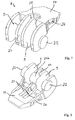
- FIG. 5 an embodiment of a multi-row terminal 1 in the form of a terminal box.
- This terminal 1 has a plurality of juxtaposed and electrically conductive interconnected Federkraftklemman till 3 of which the left is visible.
- a clamping spring 4 is attached in a busbar piece 5.
- the clamping spring 4 is in turn bent in a U-shape, so that a clamping section 6 protrudes with a clamping cap at the free end to form a nip against the busbar section 5a.
- the clamping edge is located on the busbar section 5a.
- the clamping spring 4 has in this embodiment on both sides of the clamping portion 6 actuating tabs 11th
- the busbar pieces 5 of the obliquely to the right rear juxtaposed spring terminal connections 3 can be electrically connected to each other. It is also conceivable, however, an embodiment of the terminal 1, in which two juxtaposed spring terminal connections 3 are electrically connected to each other and two or three pairs of such electrically conductive interconnected Federkraftklemman say 3 are provided. This allows two conductors each for a single-phase voltage supply connection with the terminals L (Phase), N (neutral) and PE (earth) are connected to each other, so that a power terminal is formed.
- the actuation levers 8 are respectively adjacent to the nip points, i. are arranged immediately behind the end of the formed in the insulating housing 2 conductor insertion opening 7 next to the busbar piece portion 5a and the clamping portion 6.
- the operating portions 9 of the operating lever 8 form a continuation of the wall of the respective conductor insertion opening 7, to guide an electrical conductor to the nip.
- Each actuating portion 9 cooperates with an associated actuating tab 11 of the clamping spring 4.
- the axis of rotation of the actuating lever 8 is located as the previously described embodiment below the busbar piece portion 5 in the region of the nip. The axis of rotation extends transversely to the Leiterereinsteckuttercardi, which is predetermined by the extension direction of the conductor insertion opening 7.
- the actuating arms 10 extend opposite to the conductor insertion direction L and are arranged on the upper side of the insulating housing 2. The free ends of the actuating arms 10 are in the region of the front. The free ends of the actuating arms 10 are spaced from the boundary walls of the conductor insertion opening 7 and the insulating housing 2 such that they can be grasped and pivoted by hand.
- FIG. 5 is in particular on the basis of the conductor insertion openings 7 shown in the center with the adjoining actuating lever 8 clearly that an actuating lever is provided in each case in the embodiment in each case for opening two juxtaposed Federkraftklemman say 3.
- one operating lever 8 can also be provided per clamping point.
- FIG. 6 lets a perspective view of such an actuating lever 8 from the front recognize. But it becomes clear that in the middle, central region an opening 24 is present, into which a guide wall of the insulating housing dips in order to guide the operating lever 8 tilt-proof in the insulating housing 2.
- the opening 24 is surrounded in the upper region by a circumferential collar. This serves to reinforce and stiffen the operating lever eighth
- the actuating lever has a serving as a bearing pivot pin 22 at its two lateral outer ends.
- the pivot pins 22 are received in corresponding openings in the insulating housing 2.
- the opposing actuating portions 9 thus serve as a continuation of the conductor insertion opening. 7
- the actuating lever 8 locking grooves 26 or projecting locking pins have to lock the operating lever in the closed state with the insulating 2 and to prevent inadvertent opening of the operating lever 8 with reduced force.
- FIG. 7 releases the operating lever FIG. 6 in the back view.
- the recess 24 designed as a slot in the center of the actuating lever. 8
- FIG. 8 leaves a perspective view of the actuating lever FIG. 6 and 7 recognize from the bottom. It is clear that the opening 24 is closed again in the lower area. It can also be seen that the walls that form the actuating sections 9 pass over webs 27 on the underside of the actuating arm 10, so as to stiffen the actuating arm 10 and to prevent rebounding relative to the actuating sections 9.
- the actuating sections 9 have a contour tuned to the axis of rotation D such that the opened actuating lever 8 remains self-holding in an over-center position.
- a guide surface 22a is provided for storage in the middle region.
- FIG. 9 shows a further embodiment of a terminal 1 with a plurality of view in the direction successively arranged spring terminal connections 3 and associated actuating levers 8 recognize.
- the actuating lever 8 is shown upwards in the closed position, in which the clamping spring 4 of the spring terminal connection 3 is closed.
- FIG. 10 shows the same operating lever 8 in the open position, in which the spring force terminal 3 is open.
- test opening 28 which is open to the clamping spring 4
- a test opening 28 is provided on the rear side of the insulating material housing 2 in the lower region. In this way, the voltage potential applied to the spring terminal connection can be measured by means of a test pin inserted into the test opening 28.
- FIG. 11 leaves a side view of the operating lever 8 of the terminal 1 FIGS. 9 and 10 recognize. It is clear that the actuating arm 10 of the operating portion 9 initially projects obliquely backwards and then in Leitereinsteckcardi L. Visible is also the crosspiece 10 c at the lower free end of the actuating arm 10th
- the actuating portion 9 has a nose 30 which is tuned to the position of the axis of rotation so that the open actuating lever 8 remains self-holding in an over-center position.
- FIG. 12 leaves a view of the actuator arm FIG. 11 to recognize from below.
- the structure of the actuating arm 10 with two arm portions 10a, 10b and the arm portions 10a, 10b connecting at the free end crosspiece 10c clearly.
- pivot pins 22 project, which are mounted in corresponding recesses of the insulating housing 2 of the connection terminal 1.
- the opposing inner sides of the actuating portions 9 are inclined towards the free end and have insertion bevels 29 for guiding an electrical conductor without disturbing edges.
Landscapes
- Connections Arranged To Contact A Plurality Of Conductors (AREA)
- Coupling Device And Connection With Printed Circuit (AREA)
- Details Of Connecting Devices For Male And Female Coupling (AREA)
- Clamps And Clips (AREA)
- Wire Bonding (AREA)
- Ceramic Capacitors (AREA)
- Fixing For Electrophotography (AREA)
Abstract
Eine Anschlussklemme 1, 2 mit: - mindestens einem Stromschienenstück (5) und - mindestens einer Klemmfeder (4), wobei die Anschlussklemme (1) mindestens einen aus einer Klemmfeder (4) und einem Abschnitt (5a) eines Stromschienenstücks (5) gebildeten Federkraftklemmanschluss (3, 3a, 3b) hat, um einen elektrischen Leiter zwischen einem Klemmabschnitt der Klemmfeder (4) und dem Stromschienenstückabschnitt (5a) an einer Klemmstelle anzuklemmen, - und mit einem Isolierstoffgehäuse (2), das mindestens eine zu einem zugeordneten Federkraftanschluss (3, 3a, 3b) führende und sich in eine Leitereinführungsrichtung (L) erstreckende Leitereinführungsöffnung (7) hat, - und mit mindestens einem schwenkbar gelagerten Betätigungshebel (8, 8a, 8b), der über einen Betätigungsabschnitt (9) mit mindestens einer Klemmfeder (4) zum Öffnen mindestens eines zugeordneten Federkraftklemmanschlusses (3, 3a, 3b) bei Verschwenken des Betätigungshebel (8, 8a, 8b) zusammenwirkend ausgebildet ist und eine sich an den Betätigungsabschnitt (9) anschließenden Betätigungsarm (10) hat, wird beschrieben. Die Drehachse (D) des Betätigungshebels (8, 8a, 8b) ist quer zur Leitereinführungsrichtung (L) in einer zugeordneten Leitereinführungsöffnung (7) oder der in Leitereinführungsrichtung (L) zur Klemmstelle weiterführenden Verlängerung der Leitereinführungsöffnung (7) angeordnet.A connection terminal 1, 2 with: - At least one busbar piece (5) and - At least one clamping spring (4), wherein the terminal (1) has at least one spring terminal connection (3, 3a, 3b) formed of a clamping spring (4) and a portion (5a) of a bus bar piece (5) to form an electrical conductor between a clamping portion of the clamping spring (4) and the Busbar section (5a) to be clamped at a terminal point, - And with an insulating housing (2) having at least one leading to an associated spring force connection (3, 3a, 3b) and in a conductor insertion direction (L) conductor insertion opening (7), - And with at least one pivotally mounted actuating lever (8, 8a, 8b) via an actuating portion (9) with at least one clamping spring (4) for opening at least one associated Federkraftklemmanschlusses (3, 3a, 3b) upon pivoting of the actuating lever (8, 8a, 8b) is designed to cooperate and has an actuating arm (10) adjoining the actuating portion (9), is described. The axis of rotation (D) of the actuating lever (8, 8a, 8b) is arranged transversely to the conductor insertion direction (L) in an associated conductor insertion opening (7) or in the conductor insertion direction (L) to the clamping point continuing extension of the conductor insertion opening (7).
Description
Die Erfindung betrifft eine Anschlussklemme mit:
- mindestens einem Stromschienenstück und
- mindestens einer Klemmfeder,
- und mit einem Isolierstoffgehäuse, das mindestens eine zu einem zugeordneten Federkraftklemmanschluss führende und sich in eine Leitereinführungsrichtung erstreckende Leitereinführungsöffnung hat,
- und mit mindestens einem schwenkbar gelagerten Betätigungshebel, der über einen Betätigungsabschnitt mit mindestens einer Klemmfeder zum Öffnen mindestens eines zugeordneten Federkraftklemmanschlusses bei Verschwenken des Betätigungshebels zusammenwirkend ausgebildet ist und eine sich an dem Betätigungsabschnitt anschließenden Betätigungsarm hat.
- at least one busbar piece and
- at least one clamping spring,
- and an insulating housing having at least one conductor insertion opening leading to an associated spring force terminal and extending in a conductor insertion direction,
- and with at least one pivotally mounted actuating lever, which is designed to cooperate with an actuating portion having at least one clamping spring for opening at least one associated Federkraftklemmanschlusses upon pivoting of the actuating lever and has an adjoining the actuating portion actuating arm.
Aus
Ausgehend hiervon ist es Aufgabe der vorliegenden Erfindung, eine verbesserte, möglichst kleinbauende Anschlussklemme mit einem Federkraftklemmanschluss und Betätigungshebel zu schaffen, der auch im Hinblick auf die Kraftwirkung des Betätigungshebels auf die Anschlussklemme verbessert ist.Based on this, it is an object of the present invention to provide an improved, as small as possible terminal with a Federkraftklemmanschluss and operating lever, which is also improved in terms of the force of the operating lever on the terminal.
Die Aufgabe wird durch die Anschlussklemme mit den Merkmalen des Anspruchs 1 gelöst.The object is achieved by the terminal with the features of
Bei einer gattungsgemäßen Anschlussklemme der eingangs genannten Art ist die Drehachse des Betätigungshebels quer zur Leitereinführungsrichtung in einer zugeordneten Leitereinführungsöffnung oder der in Leitereinführungsrichtung zur Klemmstelle weiterführenden Verlängerung der Leitereinführungsöffnung an geordnet.In a generic terminal of the type mentioned, the axis of rotation of the actuating lever is arranged transversely to the conductor insertion direction in an associated conductor insertion opening or in the conductor insertion direction to the clamping point continuing extension of the conductor insertion opening.
Durch die Anordnung des Betätigungshebels mit seiner Drehachse in der Leitereinführungsöffnung oder in der Flucht der Leitereinführungsöffnung zur Klemmstelle hin erfolgt die Drehung des Betätigungshebels im Bereich der Klemmstelle oder im davor liegenden Raum. Dies hat den Vorteil, dass der Betätigungshebel überaus platzsparend im Isolierstoffgehäuse aufgenommen werden kann und dabei gleichzeitig als Wand des Leitereinführungskanals zur Führung eines elektrischen Leiters dient. Damit ersetzt der Betätigungshebel einen Teil der Führungswand für einen elektrischen Leiter der Leitereinführungsöffnung.Due to the arrangement of the actuating lever with its axis of rotation in the conductor insertion opening or in the alignment of the conductor insertion opening to the clamping point, the rotation of the actuating lever in the region of the nip or in front of it takes place space. This has the advantage that the operating lever can be accommodated extremely space-saving in the insulating housing and at the same time serves as a wall of the conductor insertion channel for guiding an electrical conductor. Thus, the operating lever replaces a part of the guide wall for an electrical conductor of the conductor insertion opening.
Das Verlegen der Drehachse in den Bereich der Klemmstelle bzw. in die Flucht der davor liegenden Leitereinführungsöffnung hat zudem den kinematischen Vorteil, dass die Betätigung der Klemmfeder relativ nah zur Drehachse erfolgt, was die Hebelkräfte auf das Isolierstoffgehäuse verringert.The laying of the axis of rotation in the region of the nip or in the alignment of the preceding conductor insertion opening also has the kinematic advantage that the actuation of the clamping spring takes place relatively close to the axis of rotation, which reduces the leverage forces on the insulating material.
Es ist daher vorteilhaft, wenn der Betätigungshebel zumindest eine seitliche Begrenzungswand zur Führung eines in Leitereinführungsrichtung in eine Leitereinführungsöffnung eingeführten elektrischen Leiters zu einer zugeordneten Klemmstelle hat.It is therefore advantageous if the actuating lever has at least one lateral boundary wall for guiding an electrical conductor introduced into a conductor insertion opening in the conductor insertion direction to an associated clamping point.
Besonders vorteilhaft ist es, wenn der mindestens eine Betätigungshebel angrenzend an einen zugeordneten, die Klemmstelle bildenden Stromschienenabschnitts so angeordnet ist, dass die Drehachse des Betätigungshebels im Raum zwischen der von dem Stromschienenstückabschnitt aufgespannten Ebene und der hierzu parallelen, durch die Klemmkante der beim Umschwenken des Betätigungshebels vollständig geöffneten Klemmfeder definierten Ebene angeordnet ist. Dabei ist der Betätigungshebel vorzugsweise unterhalb des Stromschienenstückabschnitts in Leitereinführungsrichtung etwas vor oder direkt unterhalb der Klemmstelle mit seiner Drehachse positioniert. Die Stromschiene im Abschnitt, der die Klemmstelle bildet, definiert unbeachtlich etwaiger Erhebungen für eine Kontaktkante eine erste Ebene, zu der eine zweite gedachte Ebene aufgespannt wird. Diese zweite Ebene ist derart von der Ebene des Stromschienenstücks beabstandet, dass die Klemmkante einer geöffneten Klemmfeder diese Ebene berührt. Der Zwischenraum zwischen den Ebenen bildet den bevorzugten Raum, in dem die Drehachse des Betätigungshebels sein sollte, um eine überaus kompakt bauende, mechanisch stabile Anschlussklemme bereitzustellen.It when the at least one actuating lever adjacent to an associated, the nip conductor rail portion is arranged so that the axis of rotation of the actuating lever in the space between the plane spanned by the busbar section and the plane parallel thereto, by the clamping edge of the pivoting of the actuating lever fully open clamping spring defined plane is arranged. In this case, the actuating lever is preferably positioned below the conductor rail piece section in the conductor insertion direction slightly before or directly below the clamping point with its axis of rotation. The bus bar in the section forming the nip defines, irrespective of any bumps for a contact edge, a first plane to which a second imaginary plane is spanned. This second plane is spaced from the plane of the bus bar piece in such a way that the clamping edge of an opened clamping spring touches this plane. The gap between the planes forms the preferred space in which the axis of rotation of the actuating lever should be in order to provide a very compact, mechanically stable connection terminal.
Besonders vorteilhaft ist es, wenn mindestens ein Betätigungshebel in einen angrenzend an einen Klemmabschnitt des zugeordneten Stromschienenstücks eingebrachten Ausschnitt des Stromschienenstücks eintaucht. Der Betätigungshebel beaufschlagt dann mit einem Betätigungsabschnitt einen über die Breite einer zugeordneten Klemmfeder gesehen neben dem Klemmabschnitt der Klemmfeder angeordnete Betätigungslasche, um die Klemmfeder zu öffnen. Mit Hilfe des Ausschnitts an einer Seitenkante des Stromschienenstücks gelingt es, den Betätigungshebel platzsparend aufzunehmen. Über die Breite des Stromschienenstücks und der zugeordneten Klemmfeder gesehen, ist dann an dem Klemmabschnitt der Klemmfeder unterhalb dieses Ausschnitts eine Betätigungslasche herausgestellt, die dann von dem Betätigungsabschnitt des Betätigungshebels bei Verschwenken des Betätigungshebels beaufschlagt wird, um die Klemmfeder zu öffnen. Die elektrische Kontaktierung eines elektrischen Leiters erfolgt dann angrenzend an diesen Ausschnitt des Stromschienenstücks bzw. über die Breite gesehen angrenzend an die Betätigungslasche durch den Klemmabschnitt der Klemmfeder und eine vorzugsweise vorgestellte Kontaktkante des Stromschienenstücks.It is particularly advantageous if at least one actuating lever dips into a cutout of the busbar section introduced adjacent to a clamping section of the associated busbar section. The operating lever then acted upon with an actuating portion as seen across the width of an associated clamping spring next to the clamping portion of the clamping spring arranged actuating tab to open the clamping spring. With the help of the cutout on one side edge of the busbar piece, it is possible to save the operating lever to save space. Seen over the width of the busbar piece and the associated clamping spring, an actuating tab is then exposed to the clamping portion of the clamping spring below this section, which is then acted upon by the actuating portion of the actuating lever upon pivoting of the actuating lever to open the clamping spring. The electrical contacting of an electrical conductor is then adjacent to this section of the busbar piece or across the width seen adjacent to the actuating tab by the clamping portion of the clamping spring and a preferably presented contact edge of the busbar piece.
Die Betätigungslasche ist vorzugsweise von der Klemmfeder freigestellt, z.B. durch Freistanzen oder Freischneiden, und ragt schräg von dem Klemmabschnitt der Klemmfeder ab.The actuating tab is preferably free of the clamping spring, e.g. by free punching or free cutting, and protrudes obliquely from the clamping portion of the clamping spring.
Die mindestens eine Klemmfeder ist bevorzugt als eine U-förmig gebogene Klemmfeder ausgestaltet, deren freier Klemmabschnitt schräg in Richtung eines zugeordneten Stromschienenstücks weist. Mit Hilfe einer solchen U-förmig gebogenen Klemmfeder ist ein direktes Einklemmen eines elektrischen Leiters ohne vorheriges Öffnen der Klemmfeder mit dem zugeordneten Betätigungshebel möglich. dies ist auch als Direktstecktechnik bekannt.The at least one clamping spring is preferably designed as a U-shaped curved clamping spring, the free clamping portion has obliquely in the direction of an associated busbar piece. With the help of such a U-shaped clamping spring direct clamping of an electrical conductor without prior opening of the clamping spring with the associated operating lever is possible. This is also known as direct plug-in technology.
In einer bevorzugten Ausführungsform hat der mindestens eine Betätigungshebel nur auf einer Seite einen vorstehenden Drehzapfen. Dieser Drehzapfen ist dann in einer korrespondierende Öffnung des Isolierstoffgehäuses der Anschlussklemme und die durch den Drehzahl definierte Drehachse rotierbar aufgenommen. Damit ist der Betätigungshebel mit Hilfe des Drehzapfens im Isolierstoffgehäuse der Anschlussklemme einseitig rotierbar gelagert. Auf der dem einen Drehzapfen gegenüberliegenden Seite wird der Betätigungshebel hingegen nur durch eine Wand des Isolierstoffgehäuses ohne definierten Drehzapfen geführt.In a preferred embodiment, the at least one operating lever has a protruding pivot on only one side. This pivot is then rotatably received in a corresponding opening of the insulating material of the terminal and the rotation axis defined by the rotational speed. Thus, the actuating lever is rotatably supported on one side by means of the pivot in the insulating housing of the terminal. On the opposite side of a pivot side of the actuating lever, however only passed through a wall of the insulating material without defined trunnions.
Der mindestens eine Betätigungshebel hat vorzugsweise ein Betätigungsarm, der sich im geschlossenen Zustand des zugeordneten Federkraftklemmanschlusses in Leitereinsteckrichtung erstreckt. Damit endet das freie Ende des Betätigungsarms gegenüberliegend zur Leitereinstecköffnung im Bereich der Rückseite der Anschlussklemme. Damit ist eine sehr kompakte Bauweise der Anschlussklemme möglich.The at least one operating lever preferably has an actuating arm, which extends in the closed state of the associated Federkraftklemmanschlusses in Leitereinsteckrichtung. Thus ends the free end of the actuating arm opposite to the conductor insertion in the back of the terminal. This makes a very compact design of the terminal possible.
Denkbar ist aber auch, dass der mindestens eine Betätigungshebel einen Betätigungsarm hat, der sich an der Unterseite oder der Oberseite der Anschlussklemme in Leitereinsteckrichtung oder entgegengesetzt hierzu erstreckt. Für möglichst kompakt bauende Varianten der Anschlussklemme sind insbesondere Kombinationen denkbar, bei denen sich Betätigungsarme der Betätigungshebel alternierend in Leitereinsteckrichtung und entgegengesetzt hierzu erstrecken bzw. alternierend auf der Unterseite und Oberseite in gleiche Richtungen oder in alternierend in entgegengesetzte Richtungen erstrecken.It is also conceivable that the at least one operating lever has an actuating arm which extends on the underside or the top of the terminal in Leiterereinsteckrichtung or opposite thereto. Combinations of the connecting terminal which are as compact as possible are conceivable, in particular, in which actuating arms of the actuating lever extend alternately in the conductor insertion direction and in the opposite direction, or extend alternately on the underside and the upper side in the same directions or in alternating directions in opposite directions.
Diese Ausführungsformen sind insbesondere abhängig von der konkreten Kombination von Federkraftanschlussklemmen und deren räumliche Lage zueinander.These embodiments are particularly dependent on the specific combination of spring terminals and their spatial position to each other.
In einer diesbezüglich bevorzugten Ausführungsform hat die Anschlussklemme mindestens ein Paar voneinander gegenüberliegenden Federkraftanschlussklemmen mit aufeinander zulaufenden Leitereinführungsöffnungen an der einander gegenüberliegenden Vorderseite und Rückseite der Anschlussklemme. Bei dieser Ausführungsform können elektrische Leiter somit sowohl von der Vorderseite als auch von der Rückseite der Anschlussklemme in entgegengesetzte Leitereinführungsrichtungen eingesteckt und mit zugeordneten Federkraftanschlussklemmen kontaktiert werden. Jede Federkraftanschlussklemme eines solchen Paares mit einander gegenüberliegenden, gegebenenfalls versetzten Leitereinführungsöffnungen, hat jeweils einen Betätigungshebel mit einem Betätigungsarm, deren Betätigungsarme in entgegengesetzte Richtungen voneinander weisen.In a preferred embodiment, the terminal has at least one pair of opposed spring terminals with converging conductor entry openings at the opposite front and back of the terminal. In this embodiment, electrical conductors can thus be plugged in from both the front and the back of the terminal in opposite conductor insertion directions and contacted with associated spring terminals. Each spring terminal of such a pair with opposing, optionally offset conductor insertion openings, each having an actuating lever with an actuating arm, the actuating arms facing each other in opposite directions.
Die Betätigungsarme werden dabei vorzugsweise in dem Raum zwischen zwei Leitereinführungsöffnungen oberhalb bzw. unterhalb der Leitereinführungsöffnungen an der Oberseite oder Unterseite der Anschlussklemme in zugeordnete Vertiefungen des Isolierstoffgehäuses aufgenommen.The actuating arms are preferably received in the space between two conductor insertion openings above or below the conductor insertion openings at the top or bottom of the terminal in associated recesses of the insulating material.
Bei dieser Ausführungsform ist es besonders vorteilhaft, wenn die Betätigungsarme eines Paares von Betätigungshebeln auf der gleichen Seite oder alternativ auf einander gegenüberliegenden Seiten der Anschlussklemme angeordnet sind.In this embodiment, it is particularly advantageous if the actuating arms of a pair of actuating levers are arranged on the same side or alternatively on opposite sides of the connecting terminal.
Die Erfindung wird nachfolgend anhand von Ausführungsbeispielen mit den beigefügten Zeichnungen näher erläutert. Es zeigen:
Figur 1- - Seiten-Schnittansicht einer Doppel-Anschlussklemme mit zwei Federkraftanschlüssen und zugeordneten Betätigungshebeln;
Figur 2- - perspektivische Ansicht eines Federkraftklemmanschlusses mit zugeordneten Betätigungshebeln in Schließstellung,
Figur 3- - Federkraftklemmanschluss mit Betätigungshebel aus
Figur 2 Figur 4- - Seiten-Schnittansicht einer Ausführungsform einer Ausführungsform einer Anschlussklemme mit alternierend auf der Ober- und Unterseite angeordneten Betätigungshebeln;
Figur 5- - perspektivische Schnitt-Teilansicht einer mehrreihigen Anschlussklemme als Dosenklemme;
Figur 6- - perspektivische Darstellung eines Betätigungshebels für die
Anschlussklemme aus Figur 5 ; Figur 7- - perspektivische Rückseitenansicht des Betätigungshebel aus
Figur 6 ; Figur 8- - perspektivische Ansicht des Betätigungshebels aus
Figur 6 und7 von unten; Figur 9- - Seiten-Schnittansicht einer anderen Ausführungsform einer mehrreihigen Anschlussklemme in Form einer Dosenklemme mit nach hinten ausgerichteten Betätigungshebeln in Schließstellung;
Figur 10- - Seiten-Schnittansicht der
Anschlussklemme aus Figur 9 mit Betätigungshebel in Offenstellung; Figur 11- - Seitenansicht eines Betätigungshebels der Anschlussklemme aus
Figur 9 ;und 10 Figur 12- - Aufsicht auf die Unterseite des Betätigungshebels aus
Figur 11 .
- FIG. 1
- - Side sectional view of a double terminal with two spring connections and associated operating levers;
- FIG. 2
- perspective view of a spring terminal connection with associated operating levers in the closed position,
- FIG. 3
- - Spring clamp connection with operating lever off
FIG. 2 seen from the other side; - FIG. 4
- - Side sectional view of an embodiment of an embodiment of a terminal with alternately arranged on the top and bottom actuating levers;
- FIG. 5
- - perspective sectional partial view of a multi-row terminal as a terminal box;
- FIG. 6
- - Perspective view of an operating lever for the terminal off
FIG. 5 ; - FIG. 7
- - Perspective rear view of the operating lever
FIG. 6 ; - FIG. 8
- - Perspective view of the operating lever
FIG. 6 and7 from underneath; - FIG. 9
- - Side sectional view of another embodiment of a multi-row terminal in the form of a terminal box with rearwardly oriented operating levers in the closed position;
- FIG. 10
- - Side sectional view of the terminal off
FIG. 9 with actuating lever in the open position; - FIG. 11
- - Side view of an operating lever of the terminal
FIGS. 9 and 10 ; - FIG. 12
- - View from the bottom of the operating lever
FIG. 11 ,
Jeder Federkraftklemmanschluss 3a, 3b stellt eine Klemmstelle durch einen am freien, beweglichen Ende der Klemmfeder gebildeten Klemmabschnitt 6 und insbesondere durch die Klemmkante am freien Ende der Klemmfeder 4 sowie an dem dem Klemmabschnitt 6 gegenüberliegenden Stromschienenstückabschnitt 5a bereit. Zum Einführen eines elektrischen Leiters zu der Klemmstelle ist für jeden Federkraftklemmanschluss 3a, 3b eine zugeordnete Leitereinführungsöffnung 7 in das Isolierstoffgehäuse eingebracht. Die Leitereinführungsöffnung 7 hat einen Durchmesser, der an den größtmöglichen zulässigen Querschnitt mitsamt Isolierstoffmantel eines elektrischen Leiters angepasst ist.Each Federkraftklemmanschluss 3a, 3b provides a nip by a formed on the free, movable end of the clamping
Zum Öffnen der Klemmfedern 4 hat jeder Federkraftklemmanschluss 3a, 3b einen Betätigungshebel 8 mit einem Betätigungsabschnitt 9 sowie einen daran angrenzenden, sich in einer Längsrichtung erstreckenden Betätigungsarm 10.To open the clamping springs 4, each spring terminal connection 3a, 3b has an
In der
Erkennbar ist weiterhin, dass in Richtung der Breite der Klemmfeder 4 gesehen neben dem Klemmabschnitt 6 jeweils eine Betätigungslasche 11 freigestellt ist und von dem Klemmabschnitt 6 schräg abragt. Eine exenterartige, vorspringende Kontur des Betätigungsabschnitts 9 des zugeordneten Betätigungshebels 8a, 8b beaufschlagt beim Verschwenken des Betätigungshebels 8a, 8b von der Schließstellung (linker Betätigungshebel 8a) zur Offenstellung (rechter Betätigungshebel 8b) diese Betätigungslasche 11 während des Bewegungsablaufs mindestens teilweise. Auf diese Weise wird der Klemmabschnitt 6 der Klemmfeder 4 von dem angrenzenden, die Klemmstelle bildenden Stromschienenstückabschnitt 5a weg bewegt, um die Klemmfeder 4 zu öffnen.It can also be seen that, viewed in the direction of the width of the
Erkennbar ist weiterhin, dass die Betätigungshebel 8a, 8b in Vertiefungen des Isolierstoffgehäuses 2 für zur Aufnahme eines Teils des Betätigungsarmes 10 aufgenommen ist. Dabei ragt der Betätigungsarm 10 in der Schließstellung (linker Betätigungsarm 8a in
Optional ist noch eine Ausführungsform denkbar, bei der der Betätigungsarm 10 um 180° gedreht ist und in Leitereinführungsrichtung L in der Schließstellung weist. Dies ist insbesondere für eine Anschlussklemme denkbar, bei der nur ein Federkraftklemmanschluss über die dargestellte Länge der Anschlussklemme in Leitereinführungsrichtung L vorhanden ist und mehrere Federkraftklemmanschlüsse in Blickrichtung der
Bei der in
Aus der
Deutlich wird weiterhin, dass das Isolierstoffgehäuse 2 zweiteilig aufgebaut ist und ein Unterteil 2a hat, auf das ein Oberteil 2b aufgerastet ist. Hierzu tauchen Rastnasen 16 des Unterteils 2a in zugeordnete Rastöffnungen 17 des Oberteils 2b ein.It is also clear that the insulating
Deutlich wird weiterhin, dass der Klemmstelle bildende Stromschienenstückabschnitt 5a seitlich benachbart zur Klemmkante 18 einen Ausschnitt 19 in Form einer Einsenkung hat, in die der Betätigungsabschnitt 9 des Betätigungshebels 8 eintaucht. Über die Breite der Klemmfeder 4, d.h. etwa in Blickrichtung der
Deutlich wird, dass die Seitenwand des Betätigungsabschnitts 9 des Betätigungshebels 8 für einen zur Klemmstelle eingeführten elektrischen Leiter eine seitliche Begrenzungswand bildet, die zur Führung des elektrischen Leiters zur Klemmstelle genutzt wird.It is clear that the side wall of the
Hinter dem Stromschienenstückabschnitt 5a, der die Klemmstelle bildet, ist die Stromschiene 5 seitlich umgefaltet derart, dass im Abstand und parallel zu dem die Klemmstelle bildenden Stromschienenstückabschnitt 5a eine Auflagefläche 20 zur Auflage eines Anlageschenkels 21 der Klemmfeder 4 geschaffen wird.Behind the
Durch eine geeignete Kontur des Betätigungsabschnitts in Abstimmung mit der Lage der Drehachse D kann wie dargestellt ein Selbsthalten des geöffneten Betätigungshebels 8 in einer Übertotpunktlage erreicht werden.By a suitable contour of the actuating portion in coordination with the position of the axis of rotation D, as shown, a self-holding of the
Aus den
Weitere Varianten sind denkbar. Dies gilt insbesondere für Varianten von Anschlussklemmen, bei denen über die Länge der Anschlussklemme gesehen nur ein Federkraftklemmanschluss und nicht wie in den Ausführungsbeispielen nach
Dabei ist noch eine Variante denkbar, dass nicht nur die Richtung der Betätigungsarme 10 alternierend wechseln, sondern auch die Ausrichtung der Betätigungshebel alternierend so sind, dass diese aus der Oberseite und benachbart aus der Unterseite des Isolierstoffgehäuses 2 herausragen bzw. in Vertiefungen an der Oberseite und alternierend der Unterseite aufgenommen sind.In this case, another variant is conceivable that not only change the direction of the actuating
So zeigt
Die Klemmfeder 4 hat bei dieser Ausführungsform beidseits des Klemmabschnitts 6 Betätigungslaschen 11.The clamping
Die Stromschienenstücke 5 der in Blickrichtung schräg nach rechts hinten nebeneinander angeordneten Federkraftklemmanschlüsse 3 können elektrisch leitend miteinander verbunden sein. Denkbar ist aber auch eine Ausführungsform der Anschlussklemme 1, bei der jeweils zwei nebeneinander liegende Federkraftklemmanschlüsse 3 elektrisch leitend miteinander verbunden sind und zwei oder drei Paare solcher elektrisch leitend miteinander verbundenen Federkraftklemmanschlüsse 3 vorgesehen sind. Damit können jeweils zwei Leiter für einen einphasigen Spannungsversorgungsanschluss mit den Anschlüssen L (Phase), N (Neutralleiter) und PE (Erde) jeweils miteinander verbunden werden, so dass eine Netzanschlussklemme gebildet wird.The
Deutlich wird, dass die Betätigungshebel 8 jeweils neben den Klemmstellen, d.h. neben dem Stromschienenstückabschnitt 5a und dem Klemmabschnitt 6 unmittelbar hinter dem Ende der im Isolierstoffgehäuse 2 ausgeformten Leitereinführungsöffnung 7 angeordnet sind. Die Betätigungsabschnitte 9 der Betätigungshebel 8 bilden eine Fortführung der Wand der jeweiligen Leitereinführungsöffnung 7, um einen elektrischen Leiter zur Klemmstelle zu führen. Jeder Betätigungsabschnitt 9 wirkt mit einer zugeordneten Betätigungslasche 11 der Klemmfeder 4 zusammen. Die Drehachse der Betätigungshebel 8 liegt wie in dem vorher beschriebenen Ausführungsbeispiel unterhalb des Stromschienenstückabschnitts 5 im Bereich der Klemmstelle. Die Drehachse erstreckt sich quer zur Leitereinsteckrichtung, die durch die Erstreckungsrichtung der Leitereinführungsöffnung 7 vorgegeben ist.It will be appreciated that the actuation levers 8 are respectively adjacent to the nip points, i. are arranged immediately behind the end of the formed in the insulating
Deutlich wird auch, dass die Betätigungsarme 10 sich entgegengesetzt zur Leitereinsteckrichtung L erstrecken und an der Oberseite des Isolierstoffgehäuses 2 angeordnet sind. Die freien Enden der Betätigungsarme 10 liegen im Bereich der Vorderseite. Die freien Enden der Betätigungsarme 10 sind von den Begrenzungswänden der Leitereinführungsöffnung 7 bzw. dem Isolierstoffgehäuse 2 derart beabstandet, dass sie von Hand gegriffen und verschwenkt werden können.It is also clear that the actuating
Aus
Deutlich ist weiterhin, dass der Betätigungshebel an seinen beiden seitlichen äußeren Enden einen als Lager dienenden Drehzapfen 22 hat. Die Drehzapfen 22 sind in korrespondierende Öffnungen im Isolierstoffgehäuse 2 aufgenommen.It is also clear that the actuating lever has a serving as a
Erkennbar ist weiterhin, dass für jeden Federkraftklemmanschluss 3 jeweils zwei einander gegenüberliegende Betätigungsabschnitte 9 vorgesehen sind, so dass ein elektrischer Leiter beidseits an diesen Betätigungsabschnitten 9 zur Klemmstelle geführt wird, nachdem der elektrische Leiter von der seitlich umlaufend begrenzten Leitereinführungsöffnung 7 zur Klemmstelle hin aus der Leitereinführungsöffnung 7 austritt.It can also be seen that two mutually
Die einander gegenüberliegenden Betätigungsabschnitte 9 dienen somit als Fortsetzung der Leitereinführungsöffnung 7.The opposing
An den einander gegenüberliegenden Seitenkanten der Betätigungsarme 10 können die Betätigungshebel 8 Rastnuten 26 oder vorspringende Rastzapfen haben, um den Betätigungshebel im geschlossenen Zustand mit dem Isolierstoffgehäuse 2 zu verrasten und ein unbeabsichtigtes Öffnen der Betätigungshebel 8 mit reduzierter Kraft zu verhindern.At the opposite side edges of the actuating
Erkennbar ist auch der an der Oberseite des Betätigungsarms 10 umlaufende Kragen 25, der in die Wände übergeht, die die Betätigungsabschnitte 9 mit der dazwischen liegenden Öffnung 24 (Schlitz) bilden.Also recognizable is the circumferential at the top of the
Erkennbar ist weiterhin, dass zusätzlich zu den Drehzapfen 22 im mittleren Bereich eine Führungsfläche 22a zur Lagerung vorhanden ist.It can also be seen that, in addition to the pivot pins 22, a
Deutlich wird, dass der Betätigungshebel 8 mit seinem Betätigungsabschnitt 9 unmittelbar hinter der Leitereinführungsöffnung 7 wiederum seitlich neben dem Stromschienenstück 5 bzw. dem die Klemmstelle bildenden Stromschienenstückabschnitt 5a angeordnet ist. Wiederum liegt die Drehachse D in der Leitereinführungsöffnung 7 bzw. direkt dahinter und in Leitereinsteckrichtung L gesehen kurz vor der Klemmstelle sowie unterhalb des die Klemmstelle bildenden Stromschienenstückabschnitt 5a. die Betätigungsarme 10 der Betätigungshebel 8 sind in Leitereinsteckrichtung L von den Leitereinführungsöffnungen 7 weg in Richtung der Rückseite der Anschlussklemme 1 gerichtet.It is clear that the
Damit wird ein sehr kompakter Aufbau der Anschlussklemme 1 bei einfacher und zuverlässiger Betätigung des Federkraftklemmanschlusses 3 ermöglicht.This allows a very compact construction of the
Erkennbar ist weiterhin, dass an der Rückseite des Isolierstoffgehäuses 2 im unteren Bereich eine Prüföffnung 28 vorgesehen ist, die zur Klemmfeder 4 geöffnet ist. Auf diese Weise kann das an dem Federkraftklemmanschluss anliegenden Spannungspotential mit Hilfe eines in die Prüföffnung 28 eingeführten Prüfstiftes gemessen werden.It can also be seen that a
Der Betätigungsabschnitt 9 hat eine Nase 30, die auf die Lage der Drehachse so abgestimmt ist, dass der geöffnete Betätigungshebel 8 in einer Übertotpunktlage selbsthaltend verharrt.The actuating
Erkennbar ist auch, dass seitlich an den Außenseiten der Betätigungsabschnitte 9 Drehzapfen 22 herausragen, die in entsprechende Vertiefungen des Isolierstoffgehäuses 2 der Anschlussklemme 1 gelagert sind.It can also be seen that laterally on the outer sides of the
Erkennbar ist weiterhin, dass die einander gegenüberliegenden Innenseiten der Betätigungsabschnitte 9 zum freien Ende hin schräg gestellt sind und Einführungsschrägen 29 zum Führen eines elektrischen Leiters ohne störende Kanten haben.It can also be seen that the opposing inner sides of the
Claims (11)
Priority Applications (1)
| Application Number | Priority Date | Filing Date | Title |
|---|---|---|---|
| PL16187324T PL3125372T3 (en) | 2011-12-14 | 2012-12-12 | Connection terminal |
Applications Claiming Priority (2)
| Application Number | Priority Date | Filing Date | Title |
|---|---|---|---|
| DE102011056410A DE102011056410B4 (en) | 2011-12-14 | 2011-12-14 | terminal |
| EP12196722.8A EP2605335B2 (en) | 2011-12-14 | 2012-12-12 | Connection terminal |
Related Parent Applications (2)
| Application Number | Title | Priority Date | Filing Date |
|---|---|---|---|
| EP12196722.8A Division EP2605335B2 (en) | 2011-12-14 | 2012-12-12 | Connection terminal |
| EP12196722.8A Division-Into EP2605335B2 (en) | 2011-12-14 | 2012-12-12 | Connection terminal |
Publications (3)
| Publication Number | Publication Date |
|---|---|
| EP3125372A1 true EP3125372A1 (en) | 2017-02-01 |
| EP3125372B1 EP3125372B1 (en) | 2018-01-17 |
| EP3125372B2 EP3125372B2 (en) | 2024-05-01 |
Family
ID=47429791
Family Applications (3)
| Application Number | Title | Priority Date | Filing Date |
|---|---|---|---|
| EP12806010.0A Active EP2792024B1 (en) | 2011-12-14 | 2012-12-11 | Terminal having an operating lever pivotably supported about a rotational axis |
| EP16187324.5A Active EP3125372B2 (en) | 2011-12-14 | 2012-12-12 | Connection terminal |
| EP12196722.8A Active EP2605335B2 (en) | 2011-12-14 | 2012-12-12 | Connection terminal |
Family Applications Before (1)
| Application Number | Title | Priority Date | Filing Date |
|---|---|---|---|
| EP12806010.0A Active EP2792024B1 (en) | 2011-12-14 | 2012-12-11 | Terminal having an operating lever pivotably supported about a rotational axis |
Family Applications After (1)
| Application Number | Title | Priority Date | Filing Date |
|---|---|---|---|
| EP12196722.8A Active EP2605335B2 (en) | 2011-12-14 | 2012-12-12 | Connection terminal |
Country Status (13)
| Country | Link |
|---|---|
| US (2) | US9124034B2 (en) |
| EP (3) | EP2792024B1 (en) |
| JP (3) | JP6184089B2 (en) |
| KR (1) | KR101558119B1 (en) |
| CN (3) | CN103999290B (en) |
| BR (1) | BR112014014271B1 (en) |
| DE (1) | DE102011056410B4 (en) |
| DK (3) | DK2792024T3 (en) |
| ES (3) | ES2569727T3 (en) |
| PL (3) | PL2792024T3 (en) |
| PT (2) | PT3125372T (en) |
| RU (1) | RU2572567C1 (en) |
| WO (1) | WO2013087619A1 (en) |
Cited By (2)
| Publication number | Priority date | Publication date | Assignee | Title |
|---|---|---|---|---|
| EP2956992B1 (en) | 2013-02-13 | 2019-07-03 | Wago Verwaltungsgesellschaft mbH | Conductor terminal |
| EP3454422B1 (en) | 2017-09-08 | 2021-03-17 | Wago Verwaltungsgesellschaft mbH | Cable connection terminal |
Families Citing this family (96)
| Publication number | Priority date | Publication date | Assignee | Title |
|---|---|---|---|---|
| DE102012110895B4 (en) * | 2012-11-13 | 2015-03-26 | Wago Verwaltungsgesellschaft Mbh | terminal |
| DE102013101411B4 (en) | 2013-02-13 | 2018-03-22 | Wago Verwaltungsgesellschaft Mbh | Spring terminal connection and conductor terminal |
| DE102013101410A1 (en) * | 2013-02-13 | 2014-08-14 | Wago Verwaltungsgesellschaft Mbh | Spring terminal connection and conductor terminal |
| DE102013101409B4 (en) * | 2013-02-13 | 2022-01-20 | Wago Verwaltungsgesellschaft Mbh | conductor terminal |
| DE202013100635U1 (en) | 2013-02-13 | 2013-03-04 | Wago Verwaltungsgesellschaft Mbh | Spring terminal and connection terminal for electrical conductors |
| DE102013101408B4 (en) * | 2013-02-13 | 2021-01-14 | Wago Verwaltungsgesellschaft Mbh | Spring-loaded clamping element and connecting terminal |
| DE102013004666A1 (en) * | 2013-03-19 | 2014-09-25 | Phoenix Contact Gmbh & Co. Kg | Terminal block arrangement |
| DE202013101582U1 (en) | 2013-04-15 | 2014-07-16 | Weidmüller Interface GmbH & Co. KG | Spring-loaded clamping element with pivoting lever |
| USD745459S1 (en) * | 2013-06-17 | 2015-12-15 | Wago Verwaltungsgesellschaft Mbh | Electrical plug-in connector |
| DE102013110475A1 (en) * | 2013-09-23 | 2015-03-26 | Phoenix Contact Gmbh & Co. Kg | Electrical connection terminal |
| DE102013110477B4 (en) * | 2013-09-23 | 2021-11-04 | Phoenix Contact Gmbh & Co. Kg | Feed-through terminal and electrical construction equipment |
| DE102013110476A1 (en) * | 2013-09-23 | 2015-03-26 | Phoenix Contact Gmbh & Co. Kg | Cable lug device with current bar and connection terminal |
| DE102013110789B3 (en) * | 2013-09-30 | 2014-12-04 | Klaus Bruchmann Gmbh | Adapter for contacting busbars |
| DE102013111574B4 (en) * | 2013-10-21 | 2017-01-12 | Wago Verwaltungsgesellschaft Mbh | Spring terminal and connector |
| DE102014102517B4 (en) * | 2014-02-26 | 2021-06-10 | Wago Verwaltungsgesellschaft Mbh | Connecting terminal and spring-loaded terminal contact for this |
| JP6406049B2 (en) | 2014-03-26 | 2018-10-17 | 株式会社デンソー | Positive electrode material, positive electrode for non-aqueous electrolyte secondary battery and non-aqueous electrolyte secondary battery |
| US9397416B2 (en) * | 2014-08-22 | 2016-07-19 | Tyco Electronics Corporation | Electrical connector having poke-in wire contacts |
| DE102014114026B4 (en) | 2014-09-26 | 2023-03-30 | Wago Verwaltungsgesellschaft Mbh | Conductor terminal and method of assembly |
| TWM502983U (en) * | 2014-12-04 | 2015-06-11 | Switchlab Inc | Conductive wiring structure of track type electrical connection terminal |
| DE102014119030A1 (en) * | 2014-12-18 | 2016-06-23 | Phoenix Contact Gmbh & Co. Kg | terminal |
| DE102015100257A1 (en) * | 2014-12-22 | 2016-06-23 | Wago Verwaltungsgesellschaft Mbh | Conductor terminal for clamping at least one electrical conductor |
| DE102014119420B3 (en) * | 2014-12-22 | 2016-05-12 | Wago Verwaltungsgesellschaft Mbh | terminal |
| DE102014119421B4 (en) * | 2014-12-22 | 2017-02-02 | Wago Verwaltungsgesellschaft Mbh | Connection terminal and method for mounting a connection terminal |
| DE102015100823B4 (en) * | 2015-01-21 | 2021-12-09 | Phoenix Contact Gmbh & Co. Kg | Electrical connection terminal |
| CN104638455A (en) * | 2015-02-06 | 2015-05-20 | 胡和萍 | Connector for control circuit of gas water heater |
| WO2016164219A1 (en) | 2015-04-08 | 2016-10-13 | Phoenix Contact Development and Manufacturing, Inc. | Terminal block |
| CN204558667U (en) * | 2015-04-11 | 2015-08-12 | 江门市创艺电器有限公司 | A kind of terminal connector |
| CN104767045B (en) * | 2015-04-11 | 2017-03-29 | 江门市创艺电器有限公司 | A kind of terminal connector |
| KR102476138B1 (en) * | 2015-08-19 | 2022-12-14 | 삼성전자주식회사 | Connector, light source module and light source module array using the same |
| DE102015115612A1 (en) * | 2015-09-16 | 2017-03-16 | Phoenix Contact Gmbh & Co. Kg | Terminal for connecting an electrical conductor |
| DE202015105022U1 (en) * | 2015-09-22 | 2016-12-23 | Weidmüller Interface GmbH & Co. KG | Connection device for conductors |
| JP2017073284A (en) * | 2015-10-07 | 2017-04-13 | Smk株式会社 | Connector for cable connection |
| DE102015118032B4 (en) * | 2015-10-22 | 2017-11-16 | Wago Verwaltungsgesellschaft Mbh | Conductor terminal |
| DE102015119247A1 (en) | 2015-11-09 | 2017-05-11 | Wago Verwaltungsgesellschaft Mbh | connecting terminal |
| DE102015122143B4 (en) * | 2015-12-17 | 2019-02-14 | Wago Verwaltungsgesellschaft Mbh | Conductor terminal |
| JP6571517B2 (en) * | 2015-12-24 | 2019-09-04 | ヒロセ電機株式会社 | Terminal attachment / detachment device |
| CN105490038B (en) * | 2016-01-08 | 2017-12-05 | 林家鹳 | A kind of binding post |
| CN107104303B (en) * | 2016-02-19 | 2020-05-12 | 进联电子科技(上海)有限公司 | Electric connection terminal structure |
| US9466897B1 (en) * | 2016-03-01 | 2016-10-11 | Dinkle Enterprises Co., Ltd. | Double-wire terminal block structure |
| JP2017183023A (en) * | 2016-03-29 | 2017-10-05 | パナソニックIpマネジメント株式会社 | Terminal arrangement and wiring accessory |
| LU93033B1 (en) * | 2016-04-20 | 2017-11-30 | Phoenix Contact Gmbh & Co Kg Intellectual Property Licenses & Standards | Electrical terminal and method |
| WO2017207429A2 (en) * | 2016-05-30 | 2017-12-07 | Weidmüller Interface GmbH & Co. KG | Spring terminal for a conductor |
| AT15515U1 (en) * | 2016-06-13 | 2017-11-15 | Benedict Gmbh | Spring terminal |
| DE102016111627A1 (en) * | 2016-06-24 | 2017-12-28 | Wago Verwaltungsgesellschaft Mbh | Conductor terminal |
| EP3479441A1 (en) * | 2016-06-30 | 2019-05-08 | TP Elektrik Malzemeleri Sanayi Ve Ticaret Anonim Sirketi | Terminal block for plug or socket comprising wire spring contacts activated by levers |
| LU93148B1 (en) * | 2016-07-13 | 2018-01-23 | Phoenix Contact Gmbh & Co Kg Intellectual Property Licenses & Standards | terminal |
| DE102016115490B4 (en) * | 2016-08-22 | 2018-06-07 | Harting Electric Gmbh & Co. Kg | connecting element |
| DE102016115601A1 (en) | 2016-08-23 | 2018-03-01 | Wago Verwaltungsgesellschaft Mbh | Spring terminal connection |
| LU93183B1 (en) | 2016-08-25 | 2018-03-28 | Phoenix Contact Gmbh & Co Kg Intellectual Property Licenses & Standards | terminal |
| DE102016116510A1 (en) * | 2016-09-02 | 2018-03-08 | Wago Verwaltungsgesellschaft Mbh | Conductor terminal |
| EP3552275B1 (en) * | 2016-12-06 | 2021-06-30 | Raytheon Company | Connector removal tool |
| US10461444B2 (en) | 2017-01-06 | 2019-10-29 | Hubbell Incorporated | Electrical wiring devices with screwless connection terminals |
| JP6801516B2 (en) * | 2017-02-28 | 2020-12-16 | オムロン株式会社 | Terminal block |
| DE102017109694B4 (en) * | 2017-05-05 | 2022-10-06 | Wago Verwaltungsgesellschaft Mbh | terminal block |
| CN108808277B (en) * | 2017-05-05 | 2024-04-23 | 陈斌斌 | Wiring terminal |
| DE202017107800U1 (en) * | 2017-05-12 | 2018-08-17 | Electro Terminal Gmbh & Co Kg | clamp |
| CN107181074A (en) * | 2017-06-13 | 2017-09-19 | 广州高权电器灯饰有限公司 | A kind of binding post |
| TWI691132B (en) * | 2017-07-06 | 2020-04-11 | 進聯工業股份有限公司 | Conductive component structure of wire connection terminal |
| DE102017115137A1 (en) * | 2017-07-06 | 2019-01-10 | Dr. Ing. H.C. F. Porsche Aktiengesellschaft | Contact rail device for an at least partially electrically powered vehicle |
| CN108075252B (en) * | 2017-07-12 | 2023-08-01 | 安波福中央电气(上海)有限公司 | Electric connector |
| BE1025389B1 (en) * | 2017-07-14 | 2019-02-12 | Phoenix Contact Gmbh & Co. Kg | CONNECTION DEVICE FOR CONNECTING AN ELECTRICAL LINE |
| WO2019036362A1 (en) * | 2017-08-16 | 2019-02-21 | Molex, Llc | Electrical connector assembly |
| DE202017107208U1 (en) * | 2017-11-28 | 2019-03-04 | Weidmüller Interface GmbH & Co. KG | Connecting device for connecting a conductor end |
| DE202018101731U1 (en) * | 2018-03-28 | 2019-07-01 | Wago Verwaltungsgesellschaft Mbh | Conductor connection terminal, clamping spring of a conductor connection terminal and terminal block |
| DE202018101729U1 (en) * | 2018-03-28 | 2019-07-01 | Wago Verwaltungsgesellschaft Mbh | Conductor connection terminal, clamping spring of a conductor connection terminal and terminal block |
| DE202018101726U1 (en) * | 2018-03-28 | 2019-07-01 | Wago Verwaltungsgesellschaft Mbh | Conductor connection terminal, clamping spring of a conductor connection terminal and terminal block |
| USD914613S1 (en) * | 2018-04-19 | 2021-03-30 | Wago Verwaltungsgesellschaft Mbh | Electric terminal |
| CN110416749B (en) * | 2018-04-27 | 2021-02-05 | 达昌电子科技(苏州)有限公司 | Terminal block |
| TR201809553A2 (en) * | 2018-07-04 | 2018-07-23 | Eae Elektrik Asansoer Enduestrisi Insaat Sanayi Ve Ticaret Anonim Sirketi | AN ADDITIONAL CONNECTION MODULE FOR BUSBAR |
| DE102018117508B4 (en) | 2018-07-19 | 2024-01-18 | Wago Verwaltungsgesellschaft Mbh | Conductor connection terminal |
| CN109038035B (en) * | 2018-07-20 | 2020-01-07 | 上海航天科工电器研究院有限公司 | Connector adopting sliding block to lock wire quickly |
| JP7095489B2 (en) * | 2018-08-27 | 2022-07-05 | オムロン株式会社 | Connector type screwless terminal block |
| CN109149152B (en) * | 2018-09-11 | 2020-09-01 | 余姚市信亿电子科技有限公司 | Conductor connector |
| DE102018124623B4 (en) * | 2018-10-05 | 2022-07-07 | Wago Verwaltungsgesellschaft Mbh | Contact insert of a conductor terminal and conductor terminal formed therewith |
| US10418727B1 (en) * | 2018-11-15 | 2019-09-17 | Dinkle Enterprise Co., Ltd. | Rotate-to-open clamping unit and connection device having the same |
| DE202018106896U1 (en) | 2018-12-04 | 2020-03-05 | WAGO Verwaltungsgesellschaft mit beschränkter Haftung | Spring terminal |
| CN109510007B (en) * | 2018-12-05 | 2023-09-29 | 天立电机(宁波)有限公司 | Plug-in type wiring terminal |
| DE102018131794B4 (en) | 2018-12-11 | 2023-06-01 | Wago Verwaltungsgesellschaft Mbh | conductor terminal |
| US10511108B1 (en) * | 2019-01-07 | 2019-12-17 | Dinkle Enterprise Co., Ltd. | Dual-wire connector |
| DE102019104704A1 (en) * | 2019-02-25 | 2020-08-27 | Harting Electric Gmbh & Co. Kg | Connection device for electrical conductors |
| CN110112585B (en) * | 2019-05-20 | 2024-04-19 | 安费诺商用电子产品(成都)有限公司 | Quick wire locking mechanism |
| DE202019105009U1 (en) * | 2019-09-11 | 2020-12-14 | Wago Verwaltungsgesellschaft Mbh | Conductor connection terminal |
| LU101419B1 (en) | 2019-09-27 | 2021-03-31 | Phoenix Contact Gmbh & Co | Lockable connection module |
| DE202020100089U1 (en) * | 2020-01-09 | 2021-04-12 | Wago Verwaltungsgesellschaft Mbh | Conductor connection terminal |
| DE102020104077A1 (en) * | 2020-02-17 | 2021-08-19 | WAGO Verwaltungsgesellschaft mit beschränkter Haftung | Spring clamp connection |
| DE102021108316A1 (en) * | 2020-04-03 | 2021-10-07 | Phoenix Contact Gmbh & Co. Kg | Terminal and electronic device |
| US11095053B1 (en) * | 2020-06-10 | 2021-08-17 | Dinkle Enterprise Co., Ltd. | Tool-less terminal block |
| CN115715446A (en) * | 2020-07-17 | 2023-02-24 | Idec株式会社 | Connection device |
| DE202020105715U1 (en) * | 2020-10-06 | 2022-01-10 | Electro Terminal GmbH & Co. KG | Clamp with release lever |
| US11791573B2 (en) | 2021-04-15 | 2023-10-17 | Leviton Manufacturing Co., Inc. | Wire terminals and method of uses |
| US11670878B2 (en) * | 2021-05-18 | 2023-06-06 | Dinkle Enterprise Co., Ltd. | Terminal block structure |
| EP4123839A1 (en) * | 2021-07-21 | 2023-01-25 | Electro Terminal GmbH & Co KG | Electrical terminal clamp with release lever |
| DE202021103878U1 (en) | 2021-07-21 | 2022-11-04 | Electro Terminal GmbH & Co. KG | Clamp with release lever |
| WO2023095687A1 (en) * | 2021-11-29 | 2023-06-01 | Idec株式会社 | Linking device and electronic device |
| DE102022100132A1 (en) | 2022-01-04 | 2023-07-06 | Phoenix Contact Gmbh & Co. Kg | Electrical connection device |
| WO2024005776A1 (en) * | 2022-06-27 | 2024-01-04 | Ideal Industries, Inc. | Lever connector for electrical conductors |
Citations (9)
| Publication number | Priority date | Publication date | Assignee | Title |
|---|---|---|---|---|
| DE1984159U (en) * | 1967-12-07 | 1968-04-25 | Friedrich Merk Telefonbau G M | CLAMPING DEVICE FOR THE CONNECTION OF ELECTRICAL CABLES. |
| DE2922477A1 (en) * | 1978-06-05 | 1979-12-06 | Siemens Ag | Terminal block for connection of straight and stranded wires - has channel-shaped fixed contact with flat surface in movable springy contact area |
| DE8704494U1 (en) | 1987-03-26 | 1987-06-11 | Popp + Co Gmbh, 8582 Bad Berneck, De | |
| EP0821433A1 (en) * | 1996-07-25 | 1998-01-28 | Claber S.P.A. | Lever terminal for electrical connectors |
| DE29915515U1 (en) | 1999-09-03 | 2001-02-01 | Weidmueller Interface | Spring clip for connecting electrical conductors |
| JP2004319394A (en) * | 2003-04-18 | 2004-11-11 | Matsushita Electric Works Ltd | Quick connection terminal device |
| EP1605547A1 (en) * | 2004-06-10 | 2005-12-14 | Simon, S.A. | fast connecting/disconnecting device for électrical systems |
| EP1641079A1 (en) * | 2004-09-27 | 2006-03-29 | Legrand | Device with a connecting block |
| DE202009002240U1 (en) * | 2009-02-17 | 2010-07-22 | Phoenix Contact Gmbh & Co. Kg | Electrical connection terminal |
Family Cites Families (28)
| Publication number | Priority date | Publication date | Assignee | Title |
|---|---|---|---|---|
| DE1898970U (en) * | 1964-06-08 | 1964-08-20 | Wago Klemmenwerk G M B H | SPRING CLAMP. |
| DE1975279U (en) | 1967-07-15 | 1967-12-21 | Berker Geb | CONNECTING TERMINAL FOR ELECTRIC CONDUCTORS FACED IN THE BASE OF AN INSTALLATION DEVICE. |
| DE1975278U (en) * | 1967-07-15 | 1967-12-21 | Berker Geb | CONNECTING TERMINAL FOR ELECTRIC CONDUCTORS FACED IN THE BASE OF AN INSTALLATION DEVICE. |
| CH619324A5 (en) | 1977-08-10 | 1980-09-15 | Feller Ag | Screwless electrical connecting terminal |
| DE8424056U1 (en) | 1984-08-14 | 1984-11-15 | Gira Elektrotechnische Industrie Gustav Giersiepen, 5608 Radevormwald | Screwless connection terminal for electrical devices, in particular for installation devices |
| DE3743410A1 (en) * | 1987-12-21 | 1989-06-29 | Electro Terminal Gmbh | Screwless connecting terminal |
| JP2594190Y2 (en) * | 1992-08-07 | 1999-04-19 | 株式会社白山製作所 | Plug-in connection terminal |
| DE4233446C1 (en) * | 1992-10-05 | 1993-10-21 | Wieland Elektrische Industrie | Screwless electric clamp terminal - has short metal vertical section of contact piece held in position in insulating housing by retaining hooks at ends of sidewards extensions |
| JP3395540B2 (en) * | 1996-05-28 | 2003-04-14 | 松下電工株式会社 | Wire connection terminal |
| US6146187A (en) * | 1998-11-25 | 2000-11-14 | Supplie & Co. Import/Export, Inc. | Screwless terminal block |
| JP2000260501A (en) * | 1999-03-11 | 2000-09-22 | Nitto Electric Works Ltd | Terminal device |
| JP2003249283A (en) * | 2002-02-21 | 2003-09-05 | Kawamura Electric Inc | Quick jointing terminal |
| DE10261536B4 (en) | 2002-12-23 | 2009-12-10 | Wago Verwaltungsgesellschaft Mbh | Connection and connection terminal for electrical conductors |
| JP4046102B2 (en) * | 2004-05-26 | 2008-02-13 | 松下電工株式会社 | Terminal equipment |
| JP4289230B2 (en) * | 2004-06-25 | 2009-07-01 | パナソニック電工株式会社 | Fast connection terminal device |
| FR2873859B1 (en) * | 2004-07-30 | 2006-12-08 | Legrand Sa | ELECTRICAL APPARATUS COMPRISING AN AUTOMATIC CONNECTION TERMINAL |
| DE102006001812A1 (en) | 2005-12-05 | 2007-06-06 | Km Europa Metal Ag | Mold for continuous casting of metal |
| DE102006018129C5 (en) | 2006-04-19 | 2013-04-11 | Phoenix Contact Gmbh & Co. Kg | Spring terminal with a leg spring arranged in a housing |
| DE102006047254B3 (en) * | 2006-10-06 | 2008-05-21 | Abb Ag | Installation switching device e.g. line safety switch, has opening covered by covering part pivotably mounted on housing, where part has connecting area with number of connection openings that correspond to number of conductors |
| DE102007051900B4 (en) * | 2007-10-29 | 2009-09-10 | Wago Verwaltungsgesellschaft Mbh | Spring connection |
| FR2935201B1 (en) * | 2008-08-20 | 2010-09-24 | Legrand France | AUTOMATIC ELECTRICAL CONNECTION TERMINAL |
| EP2316150B1 (en) * | 2008-08-27 | 2013-04-24 | Phoenix Contact GmbH & Co. KG | Electrical terminal |
| DE102008062137B4 (en) * | 2008-12-16 | 2011-06-09 | Wago Verwaltungsgesellschaft Mbh | Conductor terminal |
| DE202009002040U1 (en) * | 2009-01-23 | 2009-08-06 | Wischemann, Heinrich | Holder for a solar module |
| JP5491837B2 (en) | 2009-12-04 | 2014-05-14 | パナソニック株式会社 | Fast connection terminal device |
| ITTO20100677A1 (en) * | 2010-08-04 | 2012-02-05 | Tyco Electronics Amp Italia Srl | ELECTRICAL CONNECTOR ACTIVATING A DIRECT CONTACT BETWEEN AN ELECTRIC CONDUCTOR AND A RESPECTIVE COUNTERPARTY |
| US8113858B1 (en) * | 2011-08-20 | 2012-02-14 | Cheng Uei Precision Industry Co., Ltd. | Cable connector having switching function |
| US20140113502A1 (en) * | 2012-09-28 | 2014-04-24 | Phoenix Contact Development & Manufacturing, Inc. | Connector Block with Spring-Loaded Electrical Terminal Assemblies |
-
2011
- 2011-12-14 DE DE102011056410A patent/DE102011056410B4/en not_active Withdrawn - After Issue
-
2012
- 2012-12-11 JP JP2012270055A patent/JP6184089B2/en active Active
- 2012-12-11 WO PCT/EP2012/075069 patent/WO2013087619A1/en active Application Filing
- 2012-12-11 JP JP2014546459A patent/JP5833774B2/en active Active
- 2012-12-11 US US14/363,578 patent/US9124034B2/en active Active
- 2012-12-11 DK DK12806010.0T patent/DK2792024T3/en active
- 2012-12-11 EP EP12806010.0A patent/EP2792024B1/en active Active
- 2012-12-11 ES ES12806010.0T patent/ES2569727T3/en active Active
- 2012-12-11 PL PL12806010T patent/PL2792024T3/en unknown
- 2012-12-11 BR BR112014014271-8A patent/BR112014014271B1/en active IP Right Grant
- 2012-12-11 RU RU2014128525/07A patent/RU2572567C1/en active
- 2012-12-11 CN CN201280062263.4A patent/CN103999290B/en active Active
- 2012-12-11 KR KR1020147016057A patent/KR101558119B1/en active IP Right Grant
- 2012-12-12 PL PL12196722.8T patent/PL2605335T5/en unknown
- 2012-12-12 ES ES16187324.5T patent/ES2662899T3/en active Active
- 2012-12-12 ES ES12196722T patent/ES2606362T5/en active Active
- 2012-12-12 DK DK16187324.5T patent/DK3125372T3/en active
- 2012-12-12 PL PL16187324T patent/PL3125372T3/en unknown
- 2012-12-12 DK DK12196722.8T patent/DK2605335T4/en active
- 2012-12-12 EP EP16187324.5A patent/EP3125372B2/en active Active
- 2012-12-12 PT PT161873245T patent/PT3125372T/en unknown
- 2012-12-12 PT PT121967228T patent/PT2605335T/en unknown
- 2012-12-12 EP EP12196722.8A patent/EP2605335B2/en active Active
- 2012-12-13 US US13/713,179 patent/US8794994B2/en active Active
- 2012-12-14 CN CN201710648680.1A patent/CN107257037A/en active Pending
- 2012-12-14 CN CN201210599279.0A patent/CN103199350B/en active Active
-
2017
- 2017-07-21 JP JP2017141792A patent/JP6626477B2/en active Active
Patent Citations (10)
| Publication number | Priority date | Publication date | Assignee | Title |
|---|---|---|---|---|
| DE1984159U (en) * | 1967-12-07 | 1968-04-25 | Friedrich Merk Telefonbau G M | CLAMPING DEVICE FOR THE CONNECTION OF ELECTRICAL CABLES. |
| DE2922477A1 (en) * | 1978-06-05 | 1979-12-06 | Siemens Ag | Terminal block for connection of straight and stranded wires - has channel-shaped fixed contact with flat surface in movable springy contact area |
| DE8704494U1 (en) | 1987-03-26 | 1987-06-11 | Popp + Co Gmbh, 8582 Bad Berneck, De | |
| EP0821433A1 (en) * | 1996-07-25 | 1998-01-28 | Claber S.P.A. | Lever terminal for electrical connectors |
| DE29915515U1 (en) | 1999-09-03 | 2001-02-01 | Weidmueller Interface | Spring clip for connecting electrical conductors |
| EP1081790A2 (en) * | 1999-09-03 | 2001-03-07 | Weidmüller Interface GmbH & Co. | Spring clip for connectiong an electrical conductor |
| JP2004319394A (en) * | 2003-04-18 | 2004-11-11 | Matsushita Electric Works Ltd | Quick connection terminal device |
| EP1605547A1 (en) * | 2004-06-10 | 2005-12-14 | Simon, S.A. | fast connecting/disconnecting device for électrical systems |
| EP1641079A1 (en) * | 2004-09-27 | 2006-03-29 | Legrand | Device with a connecting block |
| DE202009002240U1 (en) * | 2009-02-17 | 2010-07-22 | Phoenix Contact Gmbh & Co. Kg | Electrical connection terminal |
Cited By (3)
| Publication number | Priority date | Publication date | Assignee | Title |
|---|---|---|---|---|
| EP2956992B1 (en) | 2013-02-13 | 2019-07-03 | Wago Verwaltungsgesellschaft mbH | Conductor terminal |
| EP3454422B1 (en) | 2017-09-08 | 2021-03-17 | Wago Verwaltungsgesellschaft mbH | Cable connection terminal |
| EP3454422B2 (en) † | 2017-09-08 | 2024-04-17 | Wago Verwaltungsgesellschaft mbH | Cable connection terminal |
Also Published As
Similar Documents
| Publication | Publication Date | Title |
|---|---|---|
| EP2605335B1 (en) | Connection terminal | |
| EP3504755B1 (en) | Spring clamp terminal | |
| EP3298659B1 (en) | Conductor connection terminal | |
| EP3111513B1 (en) | Connection terminal and spring-loaded terminal contact therefor | |
| EP2956995B1 (en) | Conductor terminal | |
| EP2956993B1 (en) | Spring clamp contact and connecting terminal for electrical conductors | |
| EP2956992B1 (en) | Conductor terminal | |
| EP2400595B1 (en) | Connection terminal | |
| EP3507866B1 (en) | Conductor connection clamp | |
| EP3324490A1 (en) | Spring clamp contact for connecting an electrical conductor, conductor connection terminal and method for manufacturing a spring clamp contact | |
| WO2014072327A1 (en) | Spring force terminal connection and electric device therewith | |
| DE102015118032B4 (en) | Conductor terminal | |
| EP3586404B1 (en) | Spring-force connection and round plug-in connector with a large number of spring-force connections | |
| WO2014124959A1 (en) | Spring-loaded clamping element and connecting terminal | |
| DE102015118033A1 (en) | Conductor terminal | |
| EP3121904A1 (en) | Clamp component | |
| EP3145031B1 (en) | Cable connection terminal | |
| EP1523065B1 (en) | Electrical terminal | |
| WO2012038291A1 (en) | Clamping unit and connecting device comprising such a clamping unit | |
| EP3038213A1 (en) | Cable connection terminal for clamping at least one electrical conductor | |
| DE202015102561U1 (en) | Conductor terminal | |
| DE2706988A1 (en) | Bared wire ends connection system - has slider acting on V=shaped leaf spring which used to retain wire | |
| DE102019120305A1 (en) | Conductor connection terminal |
Legal Events
| Date | Code | Title | Description |
|---|---|---|---|
| PUAI | Public reference made under article 153(3) epc to a published international application that has entered the european phase |
Free format text: ORIGINAL CODE: 0009012 |
|
| STAA | Information on the status of an ep patent application or granted ep patent |
Free format text: STATUS: REQUEST FOR EXAMINATION WAS MADE |
|
| 17P | Request for examination filed |
Effective date: 20160906 |
|
| AC | Divisional application: reference to earlier application |
Ref document number: 2605335 Country of ref document: EP Kind code of ref document: P |
|
| AK | Designated contracting states |
Kind code of ref document: A1 Designated state(s): AL AT BE BG CH CY CZ DE DK EE ES FI FR GB GR HR HU IE IS IT LI LT LU LV MC MK MT NL NO PL PT RO RS SE SI SK SM TR |
|
| GRAP | Despatch of communication of intention to grant a patent |
Free format text: ORIGINAL CODE: EPIDOSNIGR1 |
|
| STAA | Information on the status of an ep patent application or granted ep patent |
Free format text: STATUS: GRANT OF PATENT IS INTENDED |
|
| RIC1 | Information provided on ipc code assigned before grant |
Ipc: H01R 9/24 20060101ALN20170824BHEP Ipc: H01R 4/48 20060101AFI20170824BHEP Ipc: H01R 107/00 20060101ALN20170824BHEP |
|
| INTG | Intention to grant announced |
Effective date: 20170920 |
|
| GRAS | Grant fee paid |
Free format text: ORIGINAL CODE: EPIDOSNIGR3 |
|
| GRAA | (expected) grant |
Free format text: ORIGINAL CODE: 0009210 |
|
| STAA | Information on the status of an ep patent application or granted ep patent |
Free format text: STATUS: THE PATENT HAS BEEN GRANTED |
|
| AC | Divisional application: reference to earlier application |
Ref document number: 2605335 Country of ref document: EP Kind code of ref document: P |
|
| AK | Designated contracting states |
Kind code of ref document: B1 Designated state(s): AL AT BE BG CH CY CZ DE DK EE ES FI FR GB GR HR HU IE IS IT LI LT LU LV MC MK MT NL NO PL PT RO RS SE SI SK SM TR |
|
| REG | Reference to a national code |
Ref country code: GB Ref legal event code: FG4D Free format text: NOT ENGLISH |
|
| REG | Reference to a national code |
Ref country code: CH Ref legal event code: EP |
|
| REG | Reference to a national code |
Ref country code: IE Ref legal event code: FG4D Free format text: LANGUAGE OF EP DOCUMENT: GERMAN |
|
| REG | Reference to a national code |
Ref country code: AT Ref legal event code: REF Ref document number: 965013 Country of ref document: AT Kind code of ref document: T Effective date: 20180215 |
|
| REG | Reference to a national code |
Ref country code: DE Ref legal event code: R096 Ref document number: 502012012043 Country of ref document: DE |
|
| REG | Reference to a national code |
Ref country code: PT Ref legal event code: SC4A Ref document number: 3125372 Country of ref document: PT Date of ref document: 20180320 Kind code of ref document: T Free format text: AVAILABILITY OF NATIONAL TRANSLATION Effective date: 20180312 |
|
| REG | Reference to a national code |
Ref country code: CH Ref legal event code: NV Representative=s name: BOHEST AG, CH |
|
| REG | Reference to a national code |
Ref country code: ES Ref legal event code: FG2A Ref document number: 2662899 Country of ref document: ES Kind code of ref document: T3 Effective date: 20180410 Ref country code: SE Ref legal event code: TRGR |
|
| REG | Reference to a national code |
Ref country code: NL Ref legal event code: FP |
|
| REG | Reference to a national code |
Ref country code: DK Ref legal event code: T3 Effective date: 20180416 |
|
| REG | Reference to a national code |
Ref country code: LT Ref legal event code: MG4D |
|
| REG | Reference to a national code |
Ref country code: NO Ref legal event code: T2 Effective date: 20180117 |
|
| REG | Reference to a national code |
Ref country code: DE Ref legal event code: R026 Ref document number: 502012012043 Country of ref document: DE |
|
| PLBI | Opposition filed |
Free format text: ORIGINAL CODE: 0009260 |
|
| PG25 | Lapsed in a contracting state [announced via postgrant information from national office to epo] |
Ref country code: CY Free format text: LAPSE BECAUSE OF FAILURE TO SUBMIT A TRANSLATION OF THE DESCRIPTION OR TO PAY THE FEE WITHIN THE PRESCRIBED TIME-LIMIT Effective date: 20180117 Ref country code: LT Free format text: LAPSE BECAUSE OF FAILURE TO SUBMIT A TRANSLATION OF THE DESCRIPTION OR TO PAY THE FEE WITHIN THE PRESCRIBED TIME-LIMIT Effective date: 20180117 Ref country code: HR Free format text: LAPSE BECAUSE OF FAILURE TO SUBMIT A TRANSLATION OF THE DESCRIPTION OR TO PAY THE FEE WITHIN THE PRESCRIBED TIME-LIMIT Effective date: 20180117 |
|
| 26 | Opposition filed |
Opponent name: UTILITY ELECTRICAL CO., LTD. Effective date: 20180720 |
|
| PG25 | Lapsed in a contracting state [announced via postgrant information from national office to epo] |
Ref country code: RS Free format text: LAPSE BECAUSE OF FAILURE TO SUBMIT A TRANSLATION OF THE DESCRIPTION OR TO PAY THE FEE WITHIN THE PRESCRIBED TIME-LIMIT Effective date: 20180117 Ref country code: IS Free format text: LAPSE BECAUSE OF FAILURE TO SUBMIT A TRANSLATION OF THE DESCRIPTION OR TO PAY THE FEE WITHIN THE PRESCRIBED TIME-LIMIT Effective date: 20180517 Ref country code: GR Free format text: LAPSE BECAUSE OF FAILURE TO SUBMIT A TRANSLATION OF THE DESCRIPTION OR TO PAY THE FEE WITHIN THE PRESCRIBED TIME-LIMIT Effective date: 20180418 Ref country code: BG Free format text: LAPSE BECAUSE OF FAILURE TO SUBMIT A TRANSLATION OF THE DESCRIPTION OR TO PAY THE FEE WITHIN THE PRESCRIBED TIME-LIMIT Effective date: 20180417 Ref country code: LV Free format text: LAPSE BECAUSE OF FAILURE TO SUBMIT A TRANSLATION OF THE DESCRIPTION OR TO PAY THE FEE WITHIN THE PRESCRIBED TIME-LIMIT Effective date: 20180117 |
|
| PG25 | Lapsed in a contracting state [announced via postgrant information from national office to epo] |
Ref country code: MT Free format text: LAPSE BECAUSE OF FAILURE TO SUBMIT A TRANSLATION OF THE DESCRIPTION OR TO PAY THE FEE WITHIN THE PRESCRIBED TIME-LIMIT Effective date: 20180117 |
|
| PLBI | Opposition filed |
Free format text: ORIGINAL CODE: 0009260 |
|
| PLAX | Notice of opposition and request to file observation + time limit sent |
Free format text: ORIGINAL CODE: EPIDOSNOBS2 |
|
| PG25 | Lapsed in a contracting state [announced via postgrant information from national office to epo] |
Ref country code: AL Free format text: LAPSE BECAUSE OF FAILURE TO SUBMIT A TRANSLATION OF THE DESCRIPTION OR TO PAY THE FEE WITHIN THE PRESCRIBED TIME-LIMIT Effective date: 20180117 Ref country code: RO Free format text: LAPSE BECAUSE OF FAILURE TO SUBMIT A TRANSLATION OF THE DESCRIPTION OR TO PAY THE FEE WITHIN THE PRESCRIBED TIME-LIMIT Effective date: 20180117 Ref country code: EE Free format text: LAPSE BECAUSE OF FAILURE TO SUBMIT A TRANSLATION OF THE DESCRIPTION OR TO PAY THE FEE WITHIN THE PRESCRIBED TIME-LIMIT Effective date: 20180117 |
|
| 26 | Opposition filed |
Opponent name: PHOENIX CONTACT GMBH & CO. KG Effective date: 20181017 |
|
| PG25 | Lapsed in a contracting state [announced via postgrant information from national office to epo] |
Ref country code: SK Free format text: LAPSE BECAUSE OF FAILURE TO SUBMIT A TRANSLATION OF THE DESCRIPTION OR TO PAY THE FEE WITHIN THE PRESCRIBED TIME-LIMIT Effective date: 20180117 Ref country code: SM Free format text: LAPSE BECAUSE OF FAILURE TO SUBMIT A TRANSLATION OF THE DESCRIPTION OR TO PAY THE FEE WITHIN THE PRESCRIBED TIME-LIMIT Effective date: 20180117 |
|
| PG25 | Lapsed in a contracting state [announced via postgrant information from national office to epo] |
Ref country code: SI Free format text: LAPSE BECAUSE OF FAILURE TO SUBMIT A TRANSLATION OF THE DESCRIPTION OR TO PAY THE FEE WITHIN THE PRESCRIBED TIME-LIMIT Effective date: 20180117 |
|
| PLAF | Information modified related to communication of a notice of opposition and request to file observations + time limit |
Free format text: ORIGINAL CODE: EPIDOSCOBS2 |
|
| PLBB | Reply of patent proprietor to notice(s) of opposition received |
Free format text: ORIGINAL CODE: EPIDOSNOBS3 |
|
| PG25 | Lapsed in a contracting state [announced via postgrant information from national office to epo] |
Ref country code: MC Free format text: LAPSE BECAUSE OF FAILURE TO SUBMIT A TRANSLATION OF THE DESCRIPTION OR TO PAY THE FEE WITHIN THE PRESCRIBED TIME-LIMIT Effective date: 20180117 Ref country code: LU Free format text: LAPSE BECAUSE OF NON-PAYMENT OF DUE FEES Effective date: 20181212 |
|
| REG | Reference to a national code |
Ref country code: IE Ref legal event code: MM4A |
|
| REG | Reference to a national code |
Ref country code: BE Ref legal event code: MM Effective date: 20181231 |
|
| PG25 | Lapsed in a contracting state [announced via postgrant information from national office to epo] |
Ref country code: IE Free format text: LAPSE BECAUSE OF NON-PAYMENT OF DUE FEES Effective date: 20181212 |
|
| PG25 | Lapsed in a contracting state [announced via postgrant information from national office to epo] |
Ref country code: BE Free format text: LAPSE BECAUSE OF NON-PAYMENT OF DUE FEES Effective date: 20181231 |
|
| PG25 | Lapsed in a contracting state [announced via postgrant information from national office to epo] |
Ref country code: HU Free format text: LAPSE BECAUSE OF FAILURE TO SUBMIT A TRANSLATION OF THE DESCRIPTION OR TO PAY THE FEE WITHIN THE PRESCRIBED TIME-LIMIT; INVALID AB INITIO Effective date: 20121212 Ref country code: MK Free format text: LAPSE BECAUSE OF NON-PAYMENT OF DUE FEES Effective date: 20180117 |
|
| PLBP | Opposition withdrawn |
Free format text: ORIGINAL CODE: 0009264 |
|
| REG | Reference to a national code |
Ref country code: FI Ref legal event code: MDE Opponent name: PHOENIX CONTACT GMBH & CO. KG Ref country code: FI Ref legal event code: MDE Opponent name: UTILITY ELECTRICAL CO., LTD. |
|
| APBM | Appeal reference recorded |
Free format text: ORIGINAL CODE: EPIDOSNREFNO |
|
| APBP | Date of receipt of notice of appeal recorded |
Free format text: ORIGINAL CODE: EPIDOSNNOA2O |
|
| APAH | Appeal reference modified |
Free format text: ORIGINAL CODE: EPIDOSCREFNO |
|
| APBM | Appeal reference recorded |
Free format text: ORIGINAL CODE: EPIDOSNREFNO |
|
| APBP | Date of receipt of notice of appeal recorded |
Free format text: ORIGINAL CODE: EPIDOSNNOA2O |
|
| APBQ | Date of receipt of statement of grounds of appeal recorded |
Free format text: ORIGINAL CODE: EPIDOSNNOA3O |
|
| APBQ | Date of receipt of statement of grounds of appeal recorded |
Free format text: ORIGINAL CODE: EPIDOSNNOA3O |
|
| PGFP | Annual fee paid to national office [announced via postgrant information from national office to epo] |
Ref country code: PL Payment date: 20221129 Year of fee payment: 11 |
|
| REG | Reference to a national code |
Ref country code: DE Ref legal event code: R082 Ref document number: 502012012043 Country of ref document: DE Representative=s name: MEISSNER BOLTE PATENTANWAELTE RECHTSANWAELTE P, DE |
|
| PGFP | Annual fee paid to national office [announced via postgrant information from national office to epo] |
Ref country code: ES Payment date: 20230118 Year of fee payment: 11 Ref country code: CH Payment date: 20221228 Year of fee payment: 11 |
|
| PGFP | Annual fee paid to national office [announced via postgrant information from national office to epo] |
Ref country code: DE Payment date: 20221227 Year of fee payment: 11 |
|
| P01 | Opt-out of the competence of the unified patent court (upc) registered |
Effective date: 20230516 |
|
| PLAB | Opposition data, opponent's data or that of the opponent's representative modified |
Free format text: ORIGINAL CODE: 0009299OPPO |
|
| R26 | Opposition filed (corrected) |
Opponent name: PHOENIX CONTACT GMBH & CO. KG Effective date: 20181017 |
|
| PGFP | Annual fee paid to national office [announced via postgrant information from national office to epo] |
Ref country code: GB Payment date: 20231219 Year of fee payment: 12 |
|
| PGFP | Annual fee paid to national office [announced via postgrant information from national office to epo] |
Ref country code: TR Payment date: 20231129 Year of fee payment: 12 Ref country code: SE Payment date: 20231222 Year of fee payment: 12 Ref country code: PT Payment date: 20231128 Year of fee payment: 12 Ref country code: NO Payment date: 20231219 Year of fee payment: 12 Ref country code: NL Payment date: 20231226 Year of fee payment: 12 Ref country code: IT Payment date: 20231221 Year of fee payment: 12 Ref country code: FR Payment date: 20231226 Year of fee payment: 12 Ref country code: FI Payment date: 20231228 Year of fee payment: 12 Ref country code: DK Payment date: 20231222 Year of fee payment: 12 Ref country code: CZ Payment date: 20231129 Year of fee payment: 12 Ref country code: AT Payment date: 20231219 Year of fee payment: 12 |
|
| APBU | Appeal procedure closed |
Free format text: ORIGINAL CODE: EPIDOSNNOA9O |
|
| PGFP | Annual fee paid to national office [announced via postgrant information from national office to epo] |
Ref country code: PL Payment date: 20231130 Year of fee payment: 12 |
|
| PUAH | Patent maintained in amended form |
Free format text: ORIGINAL CODE: 0009272 |
|
| STAA | Information on the status of an ep patent application or granted ep patent |
Free format text: STATUS: PATENT MAINTAINED AS AMENDED |
|
| PGFP | Annual fee paid to national office [announced via postgrant information from national office to epo] |
Ref country code: ES Payment date: 20240118 Year of fee payment: 12 |