EP3450256A1 - Ladeboden für den gepäckraum eines kraftfahrzeuges - Google Patents
Ladeboden für den gepäckraum eines kraftfahrzeuges Download PDFInfo
- Publication number
- EP3450256A1 EP3450256A1 EP18191888.9A EP18191888A EP3450256A1 EP 3450256 A1 EP3450256 A1 EP 3450256A1 EP 18191888 A EP18191888 A EP 18191888A EP 3450256 A1 EP3450256 A1 EP 3450256A1
- Authority
- EP
- European Patent Office
- Prior art keywords
- loading floor
- loading
- floor element
- elements
- cargo
- Prior art date
- Legal status (The legal status is an assumption and is not a legal conclusion. Google has not performed a legal analysis and makes no representation as to the accuracy of the status listed.)
- Granted
Links
Images




Classifications
-
- B—PERFORMING OPERATIONS; TRANSPORTING
- B60—VEHICLES IN GENERAL
- B60R—VEHICLES, VEHICLE FITTINGS, OR VEHICLE PARTS, NOT OTHERWISE PROVIDED FOR
- B60R5/00—Compartments within vehicle body primarily intended or sufficiently spacious for trunks, suit-cases, or the like
- B60R5/04—Compartments within vehicle body primarily intended or sufficiently spacious for trunks, suit-cases, or the like arranged at rear of vehicle
Definitions
- the invention relates to a cargo floor for the luggage compartment of a motor vehicle according to the preamble of claim 1.
- a loading floor for the luggage compartment of a motor vehicle wherein the flat loading floor has three mutually pivotable, interconnected loading floor elements.
- the individual loading floor elements are guided in rails on the side wall of the luggage compartment.
- the loading floor elements in the rails can be locked in order to obtain certain arrangements of the loading floor elements to each other.
- the loading floor is divided into three parts into a first, movable loading floor element, a second, rear loading floor element and a third, front loading floor element, wherein the second and third loading floor element are arranged side by side over the surface of the load compartment floor, and the movable loading floor Element is movably held relative to the other two cargo space elements, such that it is planarly positionable adjacent to one of the other two cargo floor elements and movable out of that position for sliding over the adjacent cargo floor element.
- the DE 10 2008 035 398 A1 discloses a cargo floor in a motor vehicle having a rear cargo floor portion surrounding a first pivot axis is pivotable, and a front loading floor portion, which is pivotable about a second pivot axis relative to the first loading floor portion, and a handle for handling the loading floor comprises.
- the handle is designed in the form of a handle between the front and the rear loading floor section, whose longitudinal axis is aligned substantially parallel to the pivot axes.
- the object of the invention is in contrast to provide a loading floor, which improves the flexible use of the available storage space and allows easy handling of the loading floor.
- both the third, front loading floor element with the second, middle loading floor element and / or the first, rear loading floor element with the second, middle loading floor element can be locked by means of locking means.
- first and second loading floor element and the second and third loading floor element are designed to be movable against each other such that they can be folded against each other by a respectively provided between the loading floor elements hinge-like connection and also on each other, and the hinged connection is a 180 degree pivotal connection, which allows a pivoting in one direction, preferably upwards, between the first and second loading floor element, and a pivoting in the opposite direction, preferably downwards, between the second and third loading floor element that different positions of the loading floor are adjustable in interaction with front and / or rear brackets on the vehicle, it is possible to provide a flexible utilization concept of the trunk.
- the loading floor in different positions by pivoting and / or folding the individual cargo floor elements to each other to accommodate different storage space requirements.
- the cargo floor elements not only take the usual flat position, but are folded on each other and also be pivoted against each other.
- the use of the front cargo floor element (with or without the middle cargo floor element) as a pivotable flap for quick access to the storage space below is possible.
- the front and middle or rear and middle loading floor element are folded onto each other to allow access to further storage space below the loading floor.
- the front brackets are arranged laterally on the vehicle such that the second, middle cargo floor element and the third, front cargo floor element can be set up together in the manner of a flap.
- the rear brackets are arranged in the region of the back of the rear seats, that the fully folded loading floor can be applied as a package to the back of the rear seats.
- the z. B. is configured slit-like, to receive the front end of the first cargo floor element when folding up the cargo floor package.
- a releasable flexible fixing is arranged.
- loading floor elements comprise locking means in order to releasably fixed to one another they can be secured in folded position (folded).
- the locking means may comprise electromagnets and / or spring-biased lever-latch assemblies (similar to the door latches) and / or hook-and-tie rubber assemblies.
- the first front loading floor element (additionally) includes laterally spaced locking means, it can be releasably fixed in a raised position on a vehicle side wall.
- the locking means are provided on both sides. These may be designed like a bolt and then engage in the extended position in recesses in the side wall for locking.
- the hinge-like connection is formed by an elastic element and a flexible element, wherein the elastic element is designed to pull the loading floor elements towards each other, and the flexible element is designed to allow the loading floor elements to pivot relative to one another and also to the foldability allow the loading floor elements to each other, it is possible to make even more flexible use of the available storage space, since the loading floor can be used in even more different configurations and positions.
- the front (closest to the end of the vehicle) loading floor element are approximately vertically placed and locked in order to divide the storage space.
- the hinge-like connection comprises an elastic element and a flexible element.
- the elastic element is configured to converge the cargo floor elements pull, ie it is stretchable, but it creates a restoring force.
- the elastic member is a strip formed of rubber or the like.
- the flexible element is designed to allow the loading floor elements to pivot relative to one another and also the foldability of the loading floor elements towards each other, i. it provides the actual hinge ability.
- the flexible element is a fabric tape.
- the elastic element between the opposite end faces of the respective cargo floor elements is arranged. So it causes a concern of the elements to each other.
- the elastic element can be fixed with one end in each case in a groove arranged in the respective end face.
- the flexible element connects in each case an upper side of a loading floor element with an underside of the other load floor element of opposite front side areas of the respective load floor elements, or vice versa.
- the loading floor according to the invention is a secondary loading floor, which is arranged spaced by spacers to a lower primary loading floor.
- the storage space can be used even more variable and retrofitting is possible.
- the spacers may be laterally arranged rails, which may also be removable or retrofittable.
- the loading floor 1 comprises a first, rear loading floor element 2, a second, middle loading floor element 3 and a third, front loading floor element 4.
- the first and second loading floor element 2, 3 and the second and third loading floor element 3, 4 are in each case via a hinge-like connection 5 against each other designed such that they are mutually pivotable and also foldable on each other, as can be Figures 2 and 3 for example.
- the loading floor 1 is a secondary loading floor, which is arranged at a distance from a spacer 6 to a lower primary loading floor 7.
- the spacers 6 are laterally arranged rails.
- the hinge-like 180 degree connection 5 is formed by at least known 180 degree hinges. Most will be arranged over the width of the cargo floor elements 2,3,4 a plurality of hinge elements. There is also the possibility that the function of the hinge is made by a fabric tape. Thus, the off FIG. 2 and 3 apparent positions and orders are taken.
- FIG. 2 the loading floor 1 is shown during pivoting or stepwise folding in the direction of the arrows.
- step I first the front loading floor element 4 is raised like a flap together with the middle loading floor element 3 opposite the rear element 2. So the storage space underneath can be reached.
- the side trunk wall each have a holder (33 in FIG. 3 ) to maintain this position, at least temporarily.
- step II buckling of the loading floor elements 4 and 3 takes place against one another, so that in step III the middle loading floor element 3 rests on the rear load floor element 2.
- the front cargo floor element 4 is placed on the middle cargo floor element 3.
- the loading floor elements can be releasably fixed to each other via locking means. This can be done automatically by clicking or manually (see. FIG. 4 . 5 and 6 ).
- step IV A very advantageous functionality results from step IV, when the locking takes place only between the third loading floor element 4 and the second loading floor element 3. Then can be dispensed with a lock between the first loading floor element 2 and the second loading floor element 3, if the whole package should be raised.
- the hinge 5 between the rear loading floor element 2 and the middle loading floor element 3 when the front loading floor element 4 is raised, all three loading floor element (2, 3, 4) are raised together as a package.
- step IV The thus obtained package arrangement (step IV) of the loading floor elements can then be folded against the back of the rear seats and locked there or fixed in order to completely create the loading floor out of the way. Therefore, on the side trunk wall each have a holder (34 in FIG. 3 ) to keep this position at least temporary. Alternatively, a fixation of the type FIG. 4 be used.
- a slot-shaped receptacle 32 is provided in the spacers 6 in the lower region of the rear side of the backrests, into which the front end of the first loading floor element slides during installation of the package. It also facilitates fixation as an abutment.
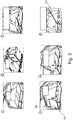
- FIG. 3 shows an overview of possible positions (1) - (6) and uses of the loading floor 1 from FIG. 1 in a trunk.
- Position 1 shows the flat fold.
- position 2 the front, nearest to the end of the vehicle loading floor element 4 is approximately vertically positioned and locked to divide the storage space. That is with a flexible and elastic connection ( Fig. 7 ) of the loading floor elements possible.
- all three elements 2, 3, 4 can be folded and stowed on each other (position (4)) to allow access completely.
- all elements can be fastened, for example via a releasable attachment to the back of the rear seat.
- front loading floor element 4 with or without the middle loading floor element 3, as a pivotable flap in position (6) for quick access to the storage space below.
- the loading floor elements 3 and 4 are placed or unfolded on the respective other loading floor elements 2 and 3, respectively, the loading floor elements can be locked to one another.
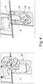
- FIG. 4 Figure 3 shows an alternative latch between cargo floor panels which lends itself well to the attachment of the three folded cargo floor panels to the rear of the rear seat back or to the locking of the cargo floor panel 3 to 4; see also FIG. 4 , Position (4).
- the lock comprises a arranged on the underside of the cargo floor element 4 receiving trough 22, in which a hook 23 can engage, which is attached via elastic clamping rubber 24 to the rear cargo floor element 2.
- the hook 23 may form a handle back 25 for an operator's finger.
- FIG. 5 a further variant is shown in which the loading floor element 4 is locked on the loading floor element 3.
- the loading floor element 4 has a handle 15, which engages in a depression 16 of the loading floor element 3.
- the handle 15 is arranged in a corresponding opening 17 in the loading floor element 4 and has a prestressed by a spring 20 lever tab 18 with a protruding locking hook 19 which engages lockingly in engagement with the recess 16.
- the spring 20 causes the automatic assumption of this position. This also facilitates the fixation of the loading floor package (position 4, cf. FIG. 3 ), since the first and second shop floor element are already connected to each other.
- FIG. 6 shows another alternative locking between loading floor elements, which is based on the use of electromagnets 26, which are for example embedded in the loading floor elements 4 (or also 3) and interact (activate) with corresponding metal inserts 27 in the loading floor element 3 (or else 2) when exposed to current. Alternatively, turning off the power may require activation.
- a switch 28 may be integrated in the corresponding load floor element (here 4).
- the alternative hinge-type connection 5 (cf. FIG. 7 ) is formed by at least one elastic element 9 and a flexible element 10. Most of the width of the cargo floor elements 2,3,4 several elastic elements 9 and a flexible elements 10 may be arranged.
- the elastic element 9 is arranged between the opposite end faces of the respective loading floor elements 2, 3 or 3, 4. So it causes a concern of the elements 2,3 and 3, 4 to each other.
- the elastic element 9 is fixed with one end in each case in a groove 11, 12 arranged in the respective front side.
- the flexible element 10 in each case connects an upper side 13 of a loading floor element to an underside 14 of the other load floor element of opposite front side areas of the respective load floor elements 2, 3 or 4, or vice versa. So it has on average about a Z-shape.
- the flexible element 10 is fixed in each case to an upper side 13 of a loading floor element and to an underside 14 of the other load floor element and passes through the front side gap loosely (without fixing).
- the cargo floor members 2,3 and 3,4 can not only assume a flat position (A), but also a raised position (B), in which the elastic member 9 is stretched and causes a restoring force, as well as one another folded position (C) in which the loading floor elements 2,3 and 3,4 lie on each other, so that the elastic element 9 is "overstretched".
- FIG. 8 should be an exemplary position (here position (2) off FIG. 3 ), in which the particular variant of the hinge-like connection FIG. 7 is used.
- the cargo floor element 4 is releasably locked to a side panel 30 of the trunk.
- the loading floor 1 lies with the loading floor elements 2, 3 on the spacers 6 on the primary loading floor 7.
- two separate loading areas A and B are created, e.g. can be used separately for dry and wet things.
- the locking of the loading floor element 4 is carried on the side panel 30 via an extendable and retractable H-shaped latch 31, wherein the edge of the loading floor element 4 is received between the webs of the "H" in the driven position of the bolt 31 ,
- the bolt 31 is designed to be extendable and retractable via a spring-loaded push-push mechanism of known type. It makes sense to lock on both sides of the vehicle.
Landscapes
- Engineering & Computer Science (AREA)
- Mechanical Engineering (AREA)
- Vehicle Step Arrangements And Article Storage (AREA)
- Seats For Vehicles (AREA)
Abstract
Description
- Die Erfindung betrifft einen Ladeboden für den Gepäckraum eines Kraftfahrzeuges nach dem Oberbegriff des Anspruchs 1.
- Es ist allgemein bekannt Gepäckräume oder Kofferräume von Kraftfahrzeugen, insbesondere PKW mit beweglichen Ladeböden zu versehen, um den zur Verfügung stehenden Stauraum gegenüber der zerklüfteten Karosserie eben auszugestalten, zu optimieren und gleichzeitig den Zugang zum meist darunterliegenden Reserverad etc. zu erlauben. Die Ladeböden werden dazu oft als mehrteilige Platten ausgeführt, wobei die Teile zueinander beweglich sind.
- In der
EP 2 292 468 A1 ist ein Ladeboden für den Gepäckraum eines Kraftfahrzeuges bekannt, wobei der flache Ladeboden drei gegeneinander schwenkbare, miteinander verbundene Ladeboden-Elemente aufweist. Die einzelnen Ladeboden-Elemente sind in Schienen an der Seitenwand des Gepäckraumes geführt. Mittels Sperreinrichtungen sind die Ladeboden-Elemente in den Schienen arretierbar, um bestimmte Anordnungen der Ladeboden-Elemente zueinander zu erhalten. - Aus der
DE 10 2004 051 622 A1 ist ein Ladeboden für den Gepäckraum eines Fahrzeuges, insbesondere ein mit einer Heckklappe versehenes Kraftfahrzeug bekannt. Der Ladeboden ist dreigeteilt in ein erstes, bewegbares Ladeboden-Element, ein zweites, hinteres Ladeboden-Element und ein drittes, vorderes Ladeboden-Element, wobei das zweite und dritte Ladeboden-Element nebeneinander über die Fläche des Laderaumbodens angeordnet sind, und das bewegbare Ladeboden-Element relativ zu den beiden anderen Laderaum-Elementen bewegbar gehalten ist, derart, dass es zu einem der anderen beiden Ladeboden-Elementen planar angrenzend positionierbar und aus dieser Position heraus zum Überschieben über das angrenzende Ladeboden-Element bewegbar ist. - Die
DE 10 2008 035 398 A1 offenbart einen Ladeboden in einem Kraftfahrzeug, der einen hinteren Ladebodenabschnitt, der um eine erste Schwenkachse verschwenkbar ist, und einen vorderen Ladebodenabschnitt, der um eine zweite Schwenkachse relativ zum ersten Ladebodenabschnitt verschwenkbar ist, sowie einen Griff zum Handhaben des Ladebodens umfasst. Zur Vereinfachung der Handhabe des Ladebodens ist der Griff in Form einer Handhabe zwischen dem vorderen und dem hinteren Ladebodenabschnitt ausgebildet, deren Längsachse im Wesentlichen parallel zu den Schwenkachsen ausgerichtet ist. - Aufgabe der Erfindung ist es demgegenüber, einen Ladeboden bereitzustellen, der die flexible Nutzung des zur Verfügung stehenden Stauraums verbessert und der eine einfache Handhabung des Ladebodens ermöglicht.
- Diese Aufgabe wird durch den in Anspruch 1 wiedergegebenen Ladeboden gelöst.
- Indem zwei Ladeboden-Elemente im zusammengefalteten Zustand mittels Arretierungsmittel gegeneinander arretierbar sind, lässt sich der dreiteilige Ladeboden sehr viel leichter handhaben und ist in der Anwendung flexibler. Dabei kann sowohl das dritte, vordere Ladeboden-Element mit dem zweiten, mittleren Ladeboden-Element und/oder das erste, hintere Ladeboden-Element mit dem zweiten, mittleren Ladeboden-Element mittels Arretierungsmittel arretierbar sein.
- Vorteilhaft ist es, wenn das erste und zweite Ladeboden-Element und das zweite und dritte Ladeboden-Element derart gegen einander bewegbar ausgestaltet sind, dass sie durch eine jeweils zwischen den Ladeboden-Elementen vorgesehene scharnierartige Verbindung gegeneinander verschwenkbar und auch aufeinander faltbar sind, und die scharnierartige Verbindung eine 180 Grad Schwenkverbindung ist, die zwischen dem ersten und zweiten Ladeboden-Element eine Verschwenkung in eine Richtung, vorzugsweise nach oben, und zwischen dem zweiten und dritten Ladeboden-Element eine Verschwenkung in die umgekehrte Richtung, vorzugsweise nach unten, erlaubt, so dass im Zusammenspiel mit vorderen und/oder hinteren Halterungen am Fahrzeug unterschiedliche Stellungen des Ladebodens einstellbar sind, es möglich ist, ein flexibles Nutzungskonzept des Kofferraums bereitzustellen.
- Es ist somit möglich, den Ladeboden in unterschiedlichen Stellungen durch Verschwenken und/oder Falten der einzelnen Ladeboden-Elemente zu einander einzustellen, um unterschiedliche Stauraumanforderungen zu erfüllen.
- So können die Ladeboden-Elemente nicht nur die übliche flache Stellung einnehmen, sondern aufeinander gefaltet werden und auch gegen einander verschwenkt werden. So ist die Verwendung des vorderen Ladebodenelements (mit oder ohne das mittlere Ladebodenelement) als verschwenkbare Klappe für einen schnellen Zugriff auf den Stauraum unterhalb möglich. Auch kann z.B. auch das vordere und mittlere bzw. hintere und mittlere Ladeboden-Element auf einander gefaltet werden, um einen Zugang zu weiterem Stauraum unterhalb des Ladebodens zu ermöglichen.
- Entsprechend können auch alle drei Teile aufeinander gefaltet und verstaut werden, um den Zugang vollständig zu erlauben. Dann wird das so erhaltene "Paket" vorzugsweise an der Rückseite der Rücksitze hochgeklappt angeordnet.
- Daher ist es von Vorteil, wenn die vorderen Halterungen derart seitlich am Fahrzeug angeordnet sind, dass das zweite, mittlere Ladeboden-Element und das dritte, vordere Ladeboden-Element gemeinsam klappenartig aufstellbar sind.
- Ferner ist es von Vorteil, wenn die hinteren Halterungen derart im Bereich der Rückseite der Rücksitze angeordnet sind, dass der komplett zusammengefaltete Ladeboden als Paket an die Rückseite der Rücksitze anlegbar ist.
- Sinnvollerweise ist im unteren Bereich am Fuß der Rückseite der Rücksitze eine Aufnahme für das erste, hinter Ladeboden-Element angeordnet, die z. B. schlitzartig ausgestaltet ist, um beim Hochklappen des Ladeboden-Pakets das Stirnende des ersten Ladeboden-Elements aufzunehmen. Somit kann ein einfacheres Hochklappen erzielt werden und diese Stellung gleichzeitig im Zusammenspiel mit einer optionalen Fixierung eingehalten werden.
- Mit anderen Worten, es ist bevorzugt, wenn zusätzlich im Bereich der Rückseite der Rücksitze eine lösbare flexible Fixierung angeordnet ist.
- Wenn die, insbesondere das zweite mittlere und erste vordere Ladeboden-Element, ladeboden-Elemente Arretierungsmittel umfassen, um aufeinander lösbar fixiert zu werden, können sie in der umgelegten Stellung (aufeinander gefaltet) gesichert werden.
- Die Arretierungsmittel können Elektromagneten und/oder federvorgespannte Hebel-Riegel-Anordnungen (ähnlich den Türverriegelungen) und/oder Haken-Spanngummi-Anordnungen umfassen.
- Wenn das erste vordere Ladeboden-Element (zusätzlich) seitlich abgeordnete Arretierungsmittel umfasst, kann es in einer aufgestellten Stellung an einer Fahrzeugseitenwand lösbar fixiert werden. Vorzugsweise sind die Arretierungsmittel an beiden Seiten vorgesehen. Diese können riegelartig ausgestaltet sein und greifen in der ausgeschobenen Stellung dann in Vertiefungen in der Seitenwand zur Arretierung ein.
- Wenn die scharnierartige Verbindung durch ein elastisches Element und ein flexibles Element ausgebildet ist, wobei das elastische Element ausgestaltet ist, um die Ladeboden-Elemente aufeinander zu ziehen, und das flexible Element ausgestaltet ist, um die Verschwenkbarkeit der Ladeboden-Elemente gegeneinander und auch die Faltbarkeit der Ladeboden-Elemente aufeinander zu erlauben, es möglich ist, den zur Verfügung stehenden Stauraum noch flexibler auszunutzen, da der Ladeboden in noch mehr unterschiedlichsten Konfigurationen und Stellungen einsetzbar ist.
- So kann z.B. das vordere (zum Ende des Fahrzeugs nächst gelegene) Ladeboden-Element etwa senkrecht aufgestellt und arretiert werden, um den Stauraum zweizuteilen.
- All diese Funktionen sind u. A. möglich aufgrund der speziellen scharnierartigen Verbindung zwischen den einzelnen Ladeboden-Elementen, d.h. zwischen dem ersten und zweiten und vorzugsweise zwischen dem zweiten und dritten.
- Die scharnierartige Verbindung umfasst ein elastisches Element und ein flexibles Element.
- Das elastische Element ist ausgestaltet, um die Ladeboden-Elemente aufeinander zu ziehen, d.h. es ist zwar dehnbar, aber erzeugt dabei eine rückstellende Kraft. Beispielsweise ist das elastische Element ein aus Kautschuk oder ähnliches gebildeter Streifen.
- Das flexible Element ist ausgestaltet, um die Verschwenkbarkeit der Ladeboden-Elemente gegeneinander und auch die Faltbarkeit der Ladeboden-Elemente aufeinander zu erlauben, d.h. es stellt die eigentliche Scharnierfähigkeit bereit. Beispielsweise ist das flexible Element ein Gewebeband.
- Vorzugsweise ist das elastische Element zwischen den gegenüberliegenden Stirnseiten der jeweiligen Ladeboden-Elemente angeordnet. So bewirkt es ein Anliegen der Elemente aneinander. Dabei kann das elastische Element mit einem Ende jeweils in einer in der jeweiligen Stirnseite angeordneten Nut fixiert sein.
- In einer bevorzugten Ausführungsform verbindet das flexible Element jeweils eine Oberseite eines Ladeboden-Elements mit einer Unterseite des anderen Ladeboden-Elements gegenüberliegender Stirnseitenbereiche der jeweiligen Ladeboden-Elemente, oder umgekehrt.
- Es versteht sich, dass auch jeweils mehr als eine scharnierartige Verbindung bzw. elastisches und flexibles Element zwischen den Ladeboden-Elementen vorgesehen sein kann.
- Denkbar ist auch, dass der erfindungsgemäße Ladeboden ein sekundärer Ladeboden ist, der über Abstandhalter zu einem unteren primären Ladeboden beabstandet angeordnet ist. Somit kann der Stauraum noch variabler ausgebnutzt werden und eine Nachrüstung ist möglich.
- Die Abstandhalter können seitlich angeordnete Schienen sein, die ggf. auch entfernbar bzw. nachrüstbar sind.
- Weitere Merkmale und Einzelheiten der Erfindung ergeben sich aus der nachfolgenden Beschreibung der Zeichnung. Es zeigen:
-
Fig. 1 eine schematische perspektivische Ansicht eines Ladebodens für den Kofferraum eines PKW; -
Fig. 2 eine schematische Ansicht auf den Ladeboden ausFigur 1 beim schrittweisen Zusammenfalten; -
Fig. 3 eine Übersicht über mögliche Stellungen und Verwendungen des Ladebodens ausFigur 1 in einem Kofferraum; -
Fig. 4 eine schematische perspektivische Ansicht auf alternative Arretierungsmittel zwischen Ladeboden-Elementen; -
Fig. 5 eine schematische Schnittansicht auf Arretierungsmittel zwischen Ladeboden-Elementen; -
Fig. 6 eine schematische Schnittansicht auf weitere alternative Arretierungsmittel zwischen Ladeboden-Elementen; und -
Fig. 7 eine schematische Ansicht auf eine alternative scharnierartige Verbindung in unterschiedlichen Stellungen; -
Fig. 8 eine schematische perspektivische Ansicht auf den Ladeboden ausFigur 7 in der aufgestellten Stellung des vorderen Ladebodens. - In den Figuren ist ein als Ganzes mit 1 bezeichneter Ladeboden gezeigt.
- Der Ladeboden 1 umfasst ein erstes, hinteres Ladeboden-Element 2, ein zweites, mittleres Ladeboden-Element 3 und ein drittes, vorderes Ladeboden-Element 4.
- Das erste und zweite Ladeboden-Element 2, 3 und das zweite und dritte Ladeboden-Element 3, 4 sind jeweils über eine scharnierartige Verbindung 5 derart gegen einander bewegbar ausgestaltet, dass sie gegeneinander verschwenkbar und aber auch aufeinander faltbar sind, wie sich dies aus
Figuren 2 und3 beispielsweise ergibt. - In der
Figur 1 ist der erfindungsgemäße Ladeboden 1 ein sekundärer Ladeboden, der über Abstandhalter 6 zu einem unteren primären Ladeboden 7 beabstandet angeordnet ist. Die Abstandhalter 6 sind seitlich angeordnete Schienen. - Die scharnierartige 180 Grad Verbindung 5 ist jeweils durch mindestens bekannte 180 Grad Scharniere ausgebildet. Meist werden über die Breite der Ladeboden-Elemente 2,3,4 mehrere Scharnierelemente angeordnet sein. Es besteht auch die Möglichkeit das die Funktion des Scharniers durch ein Gewebeband hergestellt wird. Somit können die aus
Figur 2 und3 ersichtlichen Stellungen und Anordnungen eingenommen werden. - In
Figur 2 wird der Ladeboden 1 beim Aufschwenken bzw. schrittweisen Zusammenfalten in Richtung der Pfeile gezeigt. - Im Schritt I wird zunächst das vordere Ladeboden-Element 4 klappenartig zusammen mit dem mittleren Ladeboden-Element 3 gegenüber dem hinteren Element 2 angehoben. So kann der Stauraum darunter erreicht werden. Zusätzlich ist an der seitlichen Kofferraumwandung jeweils eine Halterung (33 in
Figur 3 ) vorgesehen, um diese Stellung zumindest vorübergehend zu halten. - Dann erfolgt im Schritt II ein Abknicken der Ladeboden-Elemente 4 und 3 gegeneinander, so dass im Schritt III das mittlere Ladeboden-Element 3 auf dem hinteren Ladeboden-Element 2 aufliegt.
- Anschließend wird das vordere Ladeboden-Element 4 auf das mittlere Ladeboden-Element 3 abgelegt. Beim Ablegen bzw. aufeinander Falten können die Ladeboden-Elemente aneinander über Arretierungsmittel lösbar fixiert werden. Dies kann selbsttätig über Einrasten oder auch manuell erfolgen (vgl.
Figur 4 ,5 und6 ). - Eine sehr vorteilhafte Funktionalität ergibt sich aus Schritt IV, wenn die Arretierung nur zwischen dem dritten Ladeboden-Element 4 und dem zweiten Ladeboden-Element 3 erfolgt. Dann kann auf eine Arretierung zwischen dem ersten Ladeboden-Element 2 und dem zweiten Ladeboden-Element 3 verzichtet werden, wenn das ganze Paket angehoben werden soll. Durch das Scharnier 5 zwischen dem hinteren Ladeboden-Element 2 und dem mittleren Ladeboden-Element 3 werden, wenn das vordere Ladeboden-Element 4 angehoben wird, alle drei Ladeboden-Element (2, 3, 4) gemeinsam als Paket angehoben.
- Die so erzielte Paketanordnung (Schritt IV) der Ladeboden-Elemente kann dann gegen die Rückseite der Rücksitze aufgefaltet und dort arretiert bzw. fixiert werden, um den Ladeboden komplett aus dem Weg zu schaffen. Daher ist an der seitlichen Kofferraumwandung jeweils eine Halterung (34 in
Figur 3 ) vorgesehen, um diese Stellung zumindest vorübergehende zu halten. Alternativ kann auch eine Fixierung nach Art derFigur 4 eingesetzt werden. - Damit das Hochfalten besser gelingt, ist in den Abstandhaltern 6 im unteren Bereich der Rückseite der Rückenlehnen eine schlitzförmige Aufnahme 32 vorgesehen, in die das Stirnende des ersten Ladeboden-Elements beim Aufstellen des Pakets hineinrutscht. Die erleichtert zudem die Fixierung als Gegenlager.
-
Figur 3 zeigt eine Übersicht über mögliche Stellungen (1) - (6) und Verwendungen des Ladebodens 1 ausFigur 1 in einem Kofferraum. - Die Stellung 1 zeigt die flache Faltung. In Stellung 2 ist das vordere, zum Ende des Fahrzeugs nächst gelegene Ladeboden-Element 4 etwa senkrecht aufgestellt und arretiert, um den Stauraum zweizuteilen. Das ist mit einer flexiblen und elastischen Verbindung (
Fig. 7 ) der Ladebodenelemente möglich. - Auch möglich ist es, das vordere 4 und mittlere 3 (Stellung (3)) bzw. hintere 2 und mittlere 3 Ladeboden-Element (Stellung (5)) auf einander zu falten, um bei umgelegter Rückbank einen Zugang zu weiterem Stauraum unterhalb des Ladebodens 1 zu ermöglichen.
- Entsprechend können auch alle drei Elemente 2, 3, 4 aufeinander gefaltet und verstaut werden (Stellung (4)), um den Zugang vollständig zu erlauben. Dabei können alle Elemente z.B. über eine lösbare Befestigung an der Rückseite der Rücksitzbank festgemacht werden.
- Denkbar ist zudem die Verwendung des vorderen Ladeboden-Elements 4, mit oder ohne das mittlere Ladebodenelement 3, als verschwenkbare Klappe in Stellung (6) für einen schnellen Zugriff auf den Stauraum unterhalb.
- Wenn die Ladeboden-Elemente 3 bzw. 4 auf den jeweils anderen Ladeboden-Elementen 2 bzw. 3 abgelegt bzw. aufgefaltet sind, können die Ladeboden-Elemente aneinander arretiert werden.
-
Figur 4 zeigt eine alternative Arretierung zwischen Ladeboden-Elementen, die sich gut für die Befestigung der drei zusammengefalteten Ladeboden-Elemente an der Rückseite der Rücksitzlehne oder für die Arretierung des Ladeboden-Elements 3 zu 4 eignet; siehe auchFigur 4 , Stellung (4). - Die Arretierung umfasst ein an der Unterseite des Ladeboden-Elements 4 angeordnete Aufnahmemulde 22, in die ein Haken 23 eingreifen kann, der über elastische Spanngummis 24 an das hintere Ladeboden-Element 2 befestigt ist. Der Haken 23 kann einen Griffhinterschnitt 25 für Finger eines Bedieners ausbilden.
- In
Figur 5 ist eine weitere Variante gezeigt, in der das Ladeboden-Element 4 auf dem Ladeboden-Element 3 arretiert ist. Diese - Dazu weist das Ladeboden-Element 4 einen Griff 15 auf, der in eine Mulde 16 des Ladeboden-Elements 3 eingreift.
- Der Griff 15 ist in einem entsprechenden Durchbruch 17 in dem Ladeboden-Element 4 angeordnet und weist eine über eine Feder 20 vorgespannte Hebellasche 18 mit einem herausstehenden Arretierhaken 19 auf, der beim Eingriff in die Mulde 16 arretierend hintergreift. Die Feder 20 bewirkt die selbsttätige Einnahme dieser Stellung. Dies erleichtert auch die Fixierung des Ladebodenpakets (Stellung 4, vgl.
Figur 3 ), da das erste und zweite Ladenboden-Element bereits mit einander verbunden sind. -
Figur 6 zeigt eine weitere alternative Arretierung zwischen Ladeboden-Elementen, die auf dem Einsatz von Elektromagneten 26, beruht, die beispielsweise in die Ladeboden-Elemente 4 (oder auch 3) eingelassen sind und mit entsprechenden Metalleinsätzen 27 in dem Ladeboden-Element 3 (oder auch 2) beim Beaufschlagen mit Strom wechselwirken (aktivieren). Alternativ kann auch ein Abschalten von Strom eine Aktivierung bedingen. - Zur Regelung der Stromzufuhr kann in dem entsprechenden Ladebodenelement (hier 4) ein Schalter 28 integriert sein.
- Die alternative scharnierartige Verbindung 5 (vgl.
Figur 7 ) ist jeweils durch mindestens ein elastisches Element 9 und ein flexibles Element 10 ausgebildet. Meist werden über die Breite der Ladeboden-Elemente 2,3,4 mehrere elastische Elemente 9 und ein flexible Elemente 10 angeordnet sein. - Das elastische Element 9 ist zwischen den gegenüberliegenden Stirnseiten der jeweiligen Ladeboden-Elemente 2,3 bzw. 3, 4 angeordnet. So bewirkt es ein Anliegen der Elemente 2,3 bzw. 3, 4 aneinander. Dabei ist das elastische Element 9 mit einem Ende jeweils in einer in der jeweiligen Stirnseite angeordneten Nut 11, 12 fixiert.
- Das flexible Element 10 verbindet jeweils eine Oberseite 13 eines Ladeboden-Elements mit einer Unterseite 14 des anderen Ladeboden-Elements gegenüberliegender Stirnseitenbereiche der jeweiligen Ladeboden-Elemente 2,3 bzw. 3, 4, oder umgekehrt. Es weist also im Schnitt etwa eine Z-Form auf. Mit anderen Worten das flexible Element 10 ist jeweils einer Oberseite 13 eines Ladeboden-Elements und an einer Unterseite 14 des anderen Ladeboden-Elements fixiert und durchquert locker (ohne Fixierung) den Stirnseitenspalt.
- Somit können die Ladeboden-Elemente 2,3 bzw. 3,4 nicht nur eine flache Stellung (A) einnehmen, sondern auch eine aufgestellte Stellung (B), in der das elastische Element 9 gedehnt ist und eine rückstellende Kraft bewirkt, sowie eine aufeinander gefaltete Stellung (C), in der die Ladeboden-Elemente 2,3 bzw. 3,4 aufeinanderliegen, so dass das elastische Element 9 "überdehnt" ist.
- Anhand von
Figur 8 soll eine beispielhafte Stellung (hier Stellung (2) ausFigur 3 ) näher erläutert werden, in der die besondere Variante der scharnierartigen Verbindung ausFigur 7 eingesetzt wird. - Man erkennt die aufgeschwenkte Stellung (4) des Ladeboden-Elements 4 im Kofferraum hinter einer Rücksitzbank 29. Das Ladeboden-Elements 4 ist dabei an einer Seitenverkleidung 30 des Kofferraums lösbar arretiert.
Der Ladeboden 1 liegt mit den Ladeboden-Elementen 2, 3 auf den Abstandhaltern 6 auf dem primären Ladeboden 7 auf. - Durch das Aufschwenken entstehen zwei getrennte Ladebereiche A und B, die z.B. für trockene und nasse Sachen getrennt verwendet werden können.
- Die Arretierung des Ladeboden-Elements 4 ist an der Seitenverkleidung 30 erfolgt über einen ein- und ausfahrbaren H-förmigen Riegel 31, wobei der Rand des Ladeboden-Elements 4 zwischen den Stegen des "H" in der aus gefahrenen Stellung des Riegels 31 aufgenommen wird.
- Der Riegel 31 ist über einen durch eine Feder beaufschlagten Push-Push-Mechanismus bekannter Art ein- und ausfahrbar ausgestaltet. Sinnvollerweise erfolgt die Arretierung an beiden Fahrzeugseiten.
Claims (14)
- Ladeboden für den Gepäckraum eines Kraftfahrzeuges, insbesondere eines mit einer Heckklappe versehenes Personenkraftwagens, wobei der flache Ladeboden (1) in ein erstes, hinteres Ladeboden-Element (2), ein zweites, mittleres Ladeboden-Element (3) und ein drittes, vorderes Ladeboden-Element (4) dreigeteilt ist, wobei das erste und zweite Ladeboden-Element (2, 3) und das zweite und dritte Ladeboden-Element (3, 4) gegen verschwenkbar sind mittels einer jeweils zwischen den Ladeboden-Elementen (2, 3, 4) angeordneten scharnierartigen Verbindung (5),
dadurch gekennzeichnet, dass
das zwei Ladeboden-Elemente im zusammengefalteten Zustand mittels Arretierungsmittel gegeneinander arretierbar sind. - Ladeboden nach Anspruch 1, dadurch gekennzeichnet, dass das dritte, vordere Ladeboden-Element (4) auf dem zweiten, mittleren Ladeboden-Element (3) mittels Arretierungsmittel arretierbar ist.
- Ladeboden nach einem der vorhergehenden Ansprüche, dadurch gekennzeichnet, dass die scharnierartige Verbindung eine 180 Grad Schwenkverbindung (5) ist, die zwischen dem ersten und zweiten Ladeboden-Element (2, 3) eine Verschwenkung in eine Richtung, vorzugsweise nach oben, und zwischen dem zweiten und dritten Ladeboden-Element (3, 4) eine Verschwenkung in die umgekehrte Richtung, vorzugsweise nach unten, erlaubt.
- Ladeboden nach einem der vorherigen Ansprüche, dadurch gekennzeichnet, dass die Arretierungsmittel Elektromagneten und/oder federvorgespannte Hebel-Riegel-Anordnungen und/oder Haken-Spanngummi-Anordnungen umfassen.
- Ladeboden nach einem der vorhergehenden Ansprüche, dadurch gekennzeichnet, dass ein Ladeboden-Element seitlich abgeordnete Arretierungsmittel umfasst.
- Ladeboden nach einem der vorhergehenden Ansprüche, dadurch gekennzeichnet, dass das Arretierungsmittel ein Griff (15) des vorderen Ladebodens-Elements (4) ist, der in eine Mulde (16) des mittleren Ladeboden-Elements (3) eingreift.
- Ladeboden nach einem der vorhergehenden Ansprüche, dadurch gekennzeichnet, dass eine vordere Halterung (34) derart seitlich am Fahrzeug angeordnet ist, dass das zweite, mittlere Ladeboden-Element (3) und das dritte, vordere Ladeboden-Element (4) gemeinsam klappenartig aufstellbar sind.
- Ladeboden nach einem der vorhergehenden Ansprüche, dadurch gekennzeichnet, dass eine hintere Halterung (33) derart im Bereich der Rückseite der Rücksitze angeordnet ist, dass der komplett zusammengefaltete Ladeboden (1) als Paket an die Rückseite der Rücksitze anlegbar ist.
- Ladeboden nach Anspruch 8, dadurch gekennzeichnet, dass im unteren Bereich am Fuß der Rückseite der Rücksitze eine Aufnahme für das erste, hinter Ladeboden-Element (2) angeordnet ist.
- Ladeboden nach einem der vorhergehenden Ansprüche, dadurch gekennzeichnet, dass zusätzlich im Bereich der Rückseite der Rücksitze (29) eine lösbare flexible Fixierung angeordnet ist.
- Ladeboden nach einem der vorhergehenden Ansprüche, dadurch gekennzeichnet, dass die scharnierartige Verbindung durch ein elastisches Element (9) und ein flexibles Element (10) ausgebildet ist, wobei das elastische Element (9) ausgestaltet ist, um die Ladeboden-Elemente (2, 3) aufeinander zu ziehen, und das flexible Element (10) ausgestaltet ist, um die Verschwenkbarkeit der Ladeboden-Elemente (2, 3) gegeneinander und auch die Faltbarkeit der Ladeboden-Elemente (2, 3) aufeinander zu erlauben.
- Ladeboden nach Anspruch 9, dadurch gekennzeichnet, dass das elastische Element (9) zwischen den gegenüberliegenden Stirnseiten der jeweiligen Ladeboden-Elemente (2, 3) angeordnet ist.
- Ladeboden nach Anspruch 10, dadurch gekennzeichnet, dass das elastische Element mit einem Ende jeweils in einer in der jeweiligen Stirnseite angeordneten Nut fixiert ist.
- Ladeboden nach einem der vorhergehenden Ansprüche, dadurch gekennzeichnet, dass das flexible Element jeweils eine Oberseite eines Ladeboden-Elements mit einer Unterseite des anderen Ladeboden-Elements gegenüberliegender Stirnseitenbereiche der jeweiligen Ladeboden-Elemente, oder umgekehrt, verbindet.
Applications Claiming Priority (1)
| Application Number | Priority Date | Filing Date | Title |
|---|---|---|---|
| DE102017215224.9A DE102017215224A1 (de) | 2017-08-31 | 2017-08-31 | Ladeboden für den Gepäckraum eines Kraftfahrzeuges |
Publications (2)
| Publication Number | Publication Date |
|---|---|
| EP3450256A1 true EP3450256A1 (de) | 2019-03-06 |
| EP3450256B1 EP3450256B1 (de) | 2020-03-18 |
Family
ID=63452486
Family Applications (1)
| Application Number | Title | Priority Date | Filing Date |
|---|---|---|---|
| EP18191888.9A Active EP3450256B1 (de) | 2017-08-31 | 2018-08-31 | Ladeboden für den gepäckraum eines kraftfahrzeuges |
Country Status (2)
| Country | Link |
|---|---|
| EP (1) | EP3450256B1 (de) |
| DE (1) | DE102017215224A1 (de) |
Cited By (1)
| Publication number | Priority date | Publication date | Assignee | Title |
|---|---|---|---|---|
| GB2569149B (en) * | 2017-12-07 | 2020-11-18 | Jaguar Land Rover Ltd | Vehicle floor assembly |
Families Citing this family (2)
| Publication number | Priority date | Publication date | Assignee | Title |
|---|---|---|---|---|
| US12617327B2 (en) | 2021-03-16 | 2026-05-05 | Richard S. Maxwell | Configurable cargo support structure and method of use |
| US11851027B2 (en) | 2021-09-23 | 2023-12-26 | Hyundai Motor Company | Cargo storage assembly |
Citations (3)
| Publication number | Priority date | Publication date | Assignee | Title |
|---|---|---|---|---|
| US5570921A (en) * | 1994-06-20 | 1996-11-05 | Brooker; Gregory A. | Foldaway plastic corrugated motor vehicle carrying tote |
| DE19802077A1 (de) * | 1997-01-31 | 1998-08-06 | Volkswagen Ag | Fahrzeug mit einem Laderaum |
| EP2878489A1 (de) * | 2013-11-28 | 2015-06-03 | Volkswagen Aktiengesellschaft | Ladeboden für ein Fahrzeug |
Family Cites Families (4)
| Publication number | Priority date | Publication date | Assignee | Title |
|---|---|---|---|---|
| DE102004051622B4 (de) | 2004-10-22 | 2013-08-22 | Sortimo Speedwave Gmbh | Ladeboden für den Gepäckraum eines Fahrzeugs |
| DE102007042371A1 (de) * | 2007-09-06 | 2009-03-12 | GM Global Technology Operations, Inc., Detroit | Höhenverstellvorrichtung für den Ladeboden eines Kraftfahrzeugs |
| DE102008035398A1 (de) | 2008-07-29 | 2010-02-04 | GM Global Technology Operations, Inc., Detroit | Ladeboden in einem Kraftfahrzeug |
| CZ2009590A3 (cs) * | 2009-09-04 | 2011-03-16 | Škoda Auto a. s. | Vícedílná posuvná podlaha |
-
2017
- 2017-08-31 DE DE102017215224.9A patent/DE102017215224A1/de active Granted
-
2018
- 2018-08-31 EP EP18191888.9A patent/EP3450256B1/de active Active
Patent Citations (3)
| Publication number | Priority date | Publication date | Assignee | Title |
|---|---|---|---|---|
| US5570921A (en) * | 1994-06-20 | 1996-11-05 | Brooker; Gregory A. | Foldaway plastic corrugated motor vehicle carrying tote |
| DE19802077A1 (de) * | 1997-01-31 | 1998-08-06 | Volkswagen Ag | Fahrzeug mit einem Laderaum |
| EP2878489A1 (de) * | 2013-11-28 | 2015-06-03 | Volkswagen Aktiengesellschaft | Ladeboden für ein Fahrzeug |
Cited By (1)
| Publication number | Priority date | Publication date | Assignee | Title |
|---|---|---|---|---|
| GB2569149B (en) * | 2017-12-07 | 2020-11-18 | Jaguar Land Rover Ltd | Vehicle floor assembly |
Also Published As
| Publication number | Publication date |
|---|---|
| DE102017215224A1 (de) | 2019-02-28 |
| EP3450256B1 (de) | 2020-03-18 |
Similar Documents
| Publication | Publication Date | Title |
|---|---|---|
| DE60104511T2 (de) | Kraftfahrzeug mit verlängbaren Ladepritschen | |
| DE60128199T2 (de) | Lieferwagen | |
| EP2855208B1 (de) | Multifunktional verstellbarer ladeboden | |
| DE202017103329U1 (de) | Einziehbare Truck-Ladeflächenverlängerung mit entfernbarem Träger | |
| EP0689954A2 (de) | Sitzanordnung, insbesondere für den Lade- bzw. Fahrgastraum eines Kraftfahrzeuges | |
| DE10012590B4 (de) | Vor einem Laderaum eines Kraftfahrzeuges angeordnete Sitzanordnung | |
| DE3001430C2 (de) | Kofferraumabdeckung für Kraftfahrzeuge | |
| DE102013018037A1 (de) | Laderaumanordnung für ein Fahrzeug und Fahrzeug mit der Laderaumanordnung | |
| DE60036533T2 (de) | Abnehmbares verdeckmodul für den fahrgastraum eines kraftfahrzeuges und kraftfahrzeug ausgerüstet mit einem solchen modul | |
| EP1256488A1 (de) | Laderaumboden | |
| EP3450256B1 (de) | Ladeboden für den gepäckraum eines kraftfahrzeuges | |
| DE102021103413A1 (de) | Campingfahrzeug | |
| DE102017101513A1 (de) | Runge für einen Nutzfahrzeug- oder Anhängeraufbau | |
| DE102011108493B4 (de) | Dachträgeranordnung mit Verlagerung eines schwenkbaren Dachträgerquerholms | |
| DE102007063565A1 (de) | Kraftfahrzeugsitz | |
| DE102024107359A1 (de) | Multifunktions-frachtmaximierungsvorrichtung | |
| DE10239112A1 (de) | Sitz für Kraftfahrzeuge | |
| DE102012203906A1 (de) | Personenkraftwagen mit einem heckseitigen Laderaum sowie Laderaumanordnung hierfür | |
| DE102013105472B4 (de) | Laderaumabdeckung | |
| CH626795A5 (en) | Folding table on armrests of passenger seats | |
| DE2517077C3 (de) | Halterung für eine Abdeckplatte zwischen der Rücklehne einer hinteren Sitzbank und einer Heckklappe eines Fahrzeugs | |
| DE102004051622A1 (de) | Ladeboden für den Gepäckraum eines Fahrzeugs | |
| EP1107898A2 (de) | Seitenplanenaufhängung | |
| DE102006021720B4 (de) | Kraftfahrzeuginneneinrichtung mit einem Überbrückungsteil zwischen dem Fahrzeugsitz und dem Laderaumboden | |
| DE2927180A1 (de) | Ladeflaechenabdeckung fuer einen kombiwagen |
Legal Events
| Date | Code | Title | Description |
|---|---|---|---|
| PUAI | Public reference made under article 153(3) epc to a published international application that has entered the european phase |
Free format text: ORIGINAL CODE: 0009012 |
|
| STAA | Information on the status of an ep patent application or granted ep patent |
Free format text: STATUS: THE APPLICATION HAS BEEN PUBLISHED |
|
| AK | Designated contracting states |
Kind code of ref document: A1 Designated state(s): AL AT BE BG CH CY CZ DE DK EE ES FI FR GB GR HR HU IE IS IT LI LT LU LV MC MK MT NL NO PL PT RO RS SE SI SK SM TR |
|
| AX | Request for extension of the european patent |
Extension state: BA ME |
|
| STAA | Information on the status of an ep patent application or granted ep patent |
Free format text: STATUS: REQUEST FOR EXAMINATION WAS MADE |
|
| 17P | Request for examination filed |
Effective date: 20190906 |
|
| RBV | Designated contracting states (corrected) |
Designated state(s): AL AT BE BG CH CY CZ DE DK EE ES FI FR GB GR HR HU IE IS IT LI LT LU LV MC MK MT NL NO PL PT RO RS SE SI SK SM TR |
|
| GRAP | Despatch of communication of intention to grant a patent |
Free format text: ORIGINAL CODE: EPIDOSNIGR1 |
|
| STAA | Information on the status of an ep patent application or granted ep patent |
Free format text: STATUS: GRANT OF PATENT IS INTENDED |
|
| INTG | Intention to grant announced |
Effective date: 20200107 |
|
| GRAS | Grant fee paid |
Free format text: ORIGINAL CODE: EPIDOSNIGR3 |
|
| GRAA | (expected) grant |
Free format text: ORIGINAL CODE: 0009210 |
|
| STAA | Information on the status of an ep patent application or granted ep patent |
Free format text: STATUS: THE PATENT HAS BEEN GRANTED |
|
| AK | Designated contracting states |
Kind code of ref document: B1 Designated state(s): AL AT BE BG CH CY CZ DE DK EE ES FI FR GB GR HR HU IE IS IT LI LT LU LV MC MK MT NL NO PL PT RO RS SE SI SK SM TR |
|
| REG | Reference to a national code |
Ref country code: GB Ref legal event code: FG4D Free format text: NOT ENGLISH |
|
| REG | Reference to a national code |
Ref country code: DE Ref legal event code: R096 Ref document number: 502018000979 Country of ref document: DE |
|
| REG | Reference to a national code |
Ref country code: AT Ref legal event code: REF Ref document number: 1245550 Country of ref document: AT Kind code of ref document: T Effective date: 20200415 Ref country code: IE Ref legal event code: FG4D Free format text: LANGUAGE OF EP DOCUMENT: GERMAN |
|
| PG25 | Lapsed in a contracting state [announced via postgrant information from national office to epo] |
Ref country code: FI Free format text: LAPSE BECAUSE OF FAILURE TO SUBMIT A TRANSLATION OF THE DESCRIPTION OR TO PAY THE FEE WITHIN THE PRESCRIBED TIME-LIMIT Effective date: 20200318 Ref country code: RS Free format text: LAPSE BECAUSE OF FAILURE TO SUBMIT A TRANSLATION OF THE DESCRIPTION OR TO PAY THE FEE WITHIN THE PRESCRIBED TIME-LIMIT Effective date: 20200318 Ref country code: NO Free format text: LAPSE BECAUSE OF FAILURE TO SUBMIT A TRANSLATION OF THE DESCRIPTION OR TO PAY THE FEE WITHIN THE PRESCRIBED TIME-LIMIT Effective date: 20200618 |
|
| REG | Reference to a national code |
Ref country code: NL Ref legal event code: MP Effective date: 20200318 |
|
| PG25 | Lapsed in a contracting state [announced via postgrant information from national office to epo] |
Ref country code: HR Free format text: LAPSE BECAUSE OF FAILURE TO SUBMIT A TRANSLATION OF THE DESCRIPTION OR TO PAY THE FEE WITHIN THE PRESCRIBED TIME-LIMIT Effective date: 20200318 Ref country code: BG Free format text: LAPSE BECAUSE OF FAILURE TO SUBMIT A TRANSLATION OF THE DESCRIPTION OR TO PAY THE FEE WITHIN THE PRESCRIBED TIME-LIMIT Effective date: 20200618 Ref country code: GR Free format text: LAPSE BECAUSE OF FAILURE TO SUBMIT A TRANSLATION OF THE DESCRIPTION OR TO PAY THE FEE WITHIN THE PRESCRIBED TIME-LIMIT Effective date: 20200619 Ref country code: SE Free format text: LAPSE BECAUSE OF FAILURE TO SUBMIT A TRANSLATION OF THE DESCRIPTION OR TO PAY THE FEE WITHIN THE PRESCRIBED TIME-LIMIT Effective date: 20200318 Ref country code: LV Free format text: LAPSE BECAUSE OF FAILURE TO SUBMIT A TRANSLATION OF THE DESCRIPTION OR TO PAY THE FEE WITHIN THE PRESCRIBED TIME-LIMIT Effective date: 20200318 |
|
| REG | Reference to a national code |
Ref country code: LT Ref legal event code: MG4D |
|
| PG25 | Lapsed in a contracting state [announced via postgrant information from national office to epo] |
Ref country code: NL Free format text: LAPSE BECAUSE OF FAILURE TO SUBMIT A TRANSLATION OF THE DESCRIPTION OR TO PAY THE FEE WITHIN THE PRESCRIBED TIME-LIMIT Effective date: 20200318 |
|
| PG25 | Lapsed in a contracting state [announced via postgrant information from national office to epo] |
Ref country code: IS Free format text: LAPSE BECAUSE OF FAILURE TO SUBMIT A TRANSLATION OF THE DESCRIPTION OR TO PAY THE FEE WITHIN THE PRESCRIBED TIME-LIMIT Effective date: 20200718 Ref country code: SK Free format text: LAPSE BECAUSE OF FAILURE TO SUBMIT A TRANSLATION OF THE DESCRIPTION OR TO PAY THE FEE WITHIN THE PRESCRIBED TIME-LIMIT Effective date: 20200318 Ref country code: CZ Free format text: LAPSE BECAUSE OF FAILURE TO SUBMIT A TRANSLATION OF THE DESCRIPTION OR TO PAY THE FEE WITHIN THE PRESCRIBED TIME-LIMIT Effective date: 20200318 Ref country code: RO Free format text: LAPSE BECAUSE OF FAILURE TO SUBMIT A TRANSLATION OF THE DESCRIPTION OR TO PAY THE FEE WITHIN THE PRESCRIBED TIME-LIMIT Effective date: 20200318 Ref country code: PT Free format text: LAPSE BECAUSE OF FAILURE TO SUBMIT A TRANSLATION OF THE DESCRIPTION OR TO PAY THE FEE WITHIN THE PRESCRIBED TIME-LIMIT Effective date: 20200812 Ref country code: LT Free format text: LAPSE BECAUSE OF FAILURE TO SUBMIT A TRANSLATION OF THE DESCRIPTION OR TO PAY THE FEE WITHIN THE PRESCRIBED TIME-LIMIT Effective date: 20200318 Ref country code: SM Free format text: LAPSE BECAUSE OF FAILURE TO SUBMIT A TRANSLATION OF THE DESCRIPTION OR TO PAY THE FEE WITHIN THE PRESCRIBED TIME-LIMIT Effective date: 20200318 Ref country code: EE Free format text: LAPSE BECAUSE OF FAILURE TO SUBMIT A TRANSLATION OF THE DESCRIPTION OR TO PAY THE FEE WITHIN THE PRESCRIBED TIME-LIMIT Effective date: 20200318 |
|
| PGFP | Annual fee paid to national office [announced via postgrant information from national office to epo] |
Ref country code: FR Payment date: 20200716 Year of fee payment: 3 |
|
| REG | Reference to a national code |
Ref country code: DE Ref legal event code: R097 Ref document number: 502018000979 Country of ref document: DE |
|
| PLBE | No opposition filed within time limit |
Free format text: ORIGINAL CODE: 0009261 |
|
| STAA | Information on the status of an ep patent application or granted ep patent |
Free format text: STATUS: NO OPPOSITION FILED WITHIN TIME LIMIT |
|
| PG25 | Lapsed in a contracting state [announced via postgrant information from national office to epo] |
Ref country code: DK Free format text: LAPSE BECAUSE OF FAILURE TO SUBMIT A TRANSLATION OF THE DESCRIPTION OR TO PAY THE FEE WITHIN THE PRESCRIBED TIME-LIMIT Effective date: 20200318 Ref country code: ES Free format text: LAPSE BECAUSE OF FAILURE TO SUBMIT A TRANSLATION OF THE DESCRIPTION OR TO PAY THE FEE WITHIN THE PRESCRIBED TIME-LIMIT Effective date: 20200318 Ref country code: IT Free format text: LAPSE BECAUSE OF FAILURE TO SUBMIT A TRANSLATION OF THE DESCRIPTION OR TO PAY THE FEE WITHIN THE PRESCRIBED TIME-LIMIT Effective date: 20200318 |
|
| 26N | No opposition filed |
Effective date: 20201221 |
|
| PG25 | Lapsed in a contracting state [announced via postgrant information from national office to epo] |
Ref country code: PL Free format text: LAPSE BECAUSE OF FAILURE TO SUBMIT A TRANSLATION OF THE DESCRIPTION OR TO PAY THE FEE WITHIN THE PRESCRIBED TIME-LIMIT Effective date: 20200318 |
|
| PG25 | Lapsed in a contracting state [announced via postgrant information from national office to epo] |
Ref country code: MC Free format text: LAPSE BECAUSE OF FAILURE TO SUBMIT A TRANSLATION OF THE DESCRIPTION OR TO PAY THE FEE WITHIN THE PRESCRIBED TIME-LIMIT Effective date: 20200318 |
|
| PG25 | Lapsed in a contracting state [announced via postgrant information from national office to epo] |
Ref country code: LU Free format text: LAPSE BECAUSE OF NON-PAYMENT OF DUE FEES Effective date: 20200831 |
|
| REG | Reference to a national code |
Ref country code: BE Ref legal event code: MM Effective date: 20200831 |
|
| PG25 | Lapsed in a contracting state [announced via postgrant information from national office to epo] |
Ref country code: SI Free format text: LAPSE BECAUSE OF FAILURE TO SUBMIT A TRANSLATION OF THE DESCRIPTION OR TO PAY THE FEE WITHIN THE PRESCRIBED TIME-LIMIT Effective date: 20200318 |
|
| PG25 | Lapsed in a contracting state [announced via postgrant information from national office to epo] |
Ref country code: BE Free format text: LAPSE BECAUSE OF NON-PAYMENT OF DUE FEES Effective date: 20200831 Ref country code: IE Free format text: LAPSE BECAUSE OF NON-PAYMENT OF DUE FEES Effective date: 20200831 |
|
| REG | Reference to a national code |
Ref country code: CH Ref legal event code: PL |
|
| PG25 | Lapsed in a contracting state [announced via postgrant information from national office to epo] |
Ref country code: LI Free format text: LAPSE BECAUSE OF NON-PAYMENT OF DUE FEES Effective date: 20210831 Ref country code: CH Free format text: LAPSE BECAUSE OF NON-PAYMENT OF DUE FEES Effective date: 20210831 |
|
| PG25 | Lapsed in a contracting state [announced via postgrant information from national office to epo] |
Ref country code: TR Free format text: LAPSE BECAUSE OF FAILURE TO SUBMIT A TRANSLATION OF THE DESCRIPTION OR TO PAY THE FEE WITHIN THE PRESCRIBED TIME-LIMIT Effective date: 20200318 Ref country code: MT Free format text: LAPSE BECAUSE OF FAILURE TO SUBMIT A TRANSLATION OF THE DESCRIPTION OR TO PAY THE FEE WITHIN THE PRESCRIBED TIME-LIMIT Effective date: 20200318 Ref country code: CY Free format text: LAPSE BECAUSE OF FAILURE TO SUBMIT A TRANSLATION OF THE DESCRIPTION OR TO PAY THE FEE WITHIN THE PRESCRIBED TIME-LIMIT Effective date: 20200318 |
|
| PG25 | Lapsed in a contracting state [announced via postgrant information from national office to epo] |
Ref country code: MK Free format text: LAPSE BECAUSE OF FAILURE TO SUBMIT A TRANSLATION OF THE DESCRIPTION OR TO PAY THE FEE WITHIN THE PRESCRIBED TIME-LIMIT Effective date: 20200318 Ref country code: AL Free format text: LAPSE BECAUSE OF FAILURE TO SUBMIT A TRANSLATION OF THE DESCRIPTION OR TO PAY THE FEE WITHIN THE PRESCRIBED TIME-LIMIT Effective date: 20200318 |
|
| PG25 | Lapsed in a contracting state [announced via postgrant information from national office to epo] |
Ref country code: FR Free format text: LAPSE BECAUSE OF NON-PAYMENT OF DUE FEES Effective date: 20210831 |
|
| P01 | Opt-out of the competence of the unified patent court (upc) registered |
Effective date: 20230620 |
|
| REG | Reference to a national code |
Ref country code: AT Ref legal event code: MM01 Ref document number: 1245550 Country of ref document: AT Kind code of ref document: T Effective date: 20230831 |
|
| PG25 | Lapsed in a contracting state [announced via postgrant information from national office to epo] |
Ref country code: AT Free format text: LAPSE BECAUSE OF NON-PAYMENT OF DUE FEES Effective date: 20230831 |
|
| PG25 | Lapsed in a contracting state [announced via postgrant information from national office to epo] |
Ref country code: AT Free format text: LAPSE BECAUSE OF NON-PAYMENT OF DUE FEES Effective date: 20230831 |
|
| PGFP | Annual fee paid to national office [announced via postgrant information from national office to epo] |
Ref country code: DE Payment date: 20250709 Year of fee payment: 8 |
|
| PGFP | Annual fee paid to national office [announced via postgrant information from national office to epo] |
Ref country code: GB Payment date: 20250710 Year of fee payment: 8 |
|
| PGFP | Annual fee paid to national office [announced via postgrant information from national office to epo] |
Ref country code: AT Payment date: 20260410 Year of fee payment: 5 |