EP3449142B1 - Kupplung zum lösbaren verbinden von zwei wellen - Google Patents
Kupplung zum lösbaren verbinden von zwei wellen Download PDFInfo
- Publication number
- EP3449142B1 EP3449142B1 EP17716913.3A EP17716913A EP3449142B1 EP 3449142 B1 EP3449142 B1 EP 3449142B1 EP 17716913 A EP17716913 A EP 17716913A EP 3449142 B1 EP3449142 B1 EP 3449142B1
- Authority
- EP
- European Patent Office
- Prior art keywords
- coupling
- coupling half
- force transfer
- driver
- shaft
- Prior art date
- Legal status (The legal status is an assumption and is not a legal conclusion. Google has not performed a legal analysis and makes no representation as to the accuracy of the status listed.)
- Active
Links
Images



Classifications
-
- F—MECHANICAL ENGINEERING; LIGHTING; HEATING; WEAPONS; BLASTING
- F16—ENGINEERING ELEMENTS AND UNITS; GENERAL MEASURES FOR PRODUCING AND MAINTAINING EFFECTIVE FUNCTIONING OF MACHINES OR INSTALLATIONS; THERMAL INSULATION IN GENERAL
- F16D—COUPLINGS FOR TRANSMITTING ROTATION; CLUTCHES; BRAKES
- F16D1/00—Couplings for rigidly connecting two coaxial shafts or other movable machine elements
- F16D1/10—Quick-acting couplings in which the parts are connected by simply bringing them together axially
-
- F—MECHANICAL ENGINEERING; LIGHTING; HEATING; WEAPONS; BLASTING
- F16—ENGINEERING ELEMENTS AND UNITS; GENERAL MEASURES FOR PRODUCING AND MAINTAINING EFFECTIVE FUNCTIONING OF MACHINES OR INSTALLATIONS; THERMAL INSULATION IN GENERAL
- F16D—COUPLINGS FOR TRANSMITTING ROTATION; CLUTCHES; BRAKES
- F16D1/00—Couplings for rigidly connecting two coaxial shafts or other movable machine elements
- F16D1/02—Couplings for rigidly connecting two coaxial shafts or other movable machine elements for connecting two abutting shafts or the like
-
- F—MECHANICAL ENGINEERING; LIGHTING; HEATING; WEAPONS; BLASTING
- F16—ENGINEERING ELEMENTS AND UNITS; GENERAL MEASURES FOR PRODUCING AND MAINTAINING EFFECTIVE FUNCTIONING OF MACHINES OR INSTALLATIONS; THERMAL INSULATION IN GENERAL
- F16D—COUPLINGS FOR TRANSMITTING ROTATION; CLUTCHES; BRAKES
- F16D1/00—Couplings for rigidly connecting two coaxial shafts or other movable machine elements
- F16D1/10—Quick-acting couplings in which the parts are connected by simply bringing them together axially
- F16D1/108—Quick-acting couplings in which the parts are connected by simply bringing them together axially having retaining means rotating with the coupling and acting by interengaging parts, i.e. positive coupling
- F16D1/112—Quick-acting couplings in which the parts are connected by simply bringing them together axially having retaining means rotating with the coupling and acting by interengaging parts, i.e. positive coupling the interengaging parts comprising torque-transmitting surfaces, e.g. bayonet joints
-
- F—MECHANICAL ENGINEERING; LIGHTING; HEATING; WEAPONS; BLASTING
- F16—ENGINEERING ELEMENTS AND UNITS; GENERAL MEASURES FOR PRODUCING AND MAINTAINING EFFECTIVE FUNCTIONING OF MACHINES OR INSTALLATIONS; THERMAL INSULATION IN GENERAL
- F16D—COUPLINGS FOR TRANSMITTING ROTATION; CLUTCHES; BRAKES
- F16D1/00—Couplings for rigidly connecting two coaxial shafts or other movable machine elements
- F16D1/10—Quick-acting couplings in which the parts are connected by simply bringing them together axially
- F16D1/108—Quick-acting couplings in which the parts are connected by simply bringing them together axially having retaining means rotating with the coupling and acting by interengaging parts, i.e. positive coupling
- F16D1/116—Quick-acting couplings in which the parts are connected by simply bringing them together axially having retaining means rotating with the coupling and acting by interengaging parts, i.e. positive coupling the interengaging parts including a continuous or interrupted circumferential groove in the surface of one of the coupling parts
-
- F—MECHANICAL ENGINEERING; LIGHTING; HEATING; WEAPONS; BLASTING
- F04—POSITIVE - DISPLACEMENT MACHINES FOR LIQUIDS; PUMPS FOR LIQUIDS OR ELASTIC FLUIDS
- F04C—ROTARY-PISTON, OR OSCILLATING-PISTON, POSITIVE-DISPLACEMENT MACHINES FOR LIQUIDS; ROTARY-PISTON, OR OSCILLATING-PISTON, POSITIVE-DISPLACEMENT PUMPS
- F04C15/00—Component parts, details or accessories of machines, pumps or pumping installations, not provided for in groups F04C2/00 - F04C14/00
- F04C15/0057—Driving elements, brakes, couplings, transmission specially adapted for machines or pumps
-
- F—MECHANICAL ENGINEERING; LIGHTING; HEATING; WEAPONS; BLASTING
- F04—POSITIVE - DISPLACEMENT MACHINES FOR LIQUIDS; PUMPS FOR LIQUIDS OR ELASTIC FLUIDS
- F04C—ROTARY-PISTON, OR OSCILLATING-PISTON, POSITIVE-DISPLACEMENT MACHINES FOR LIQUIDS; ROTARY-PISTON, OR OSCILLATING-PISTON, POSITIVE-DISPLACEMENT PUMPS
- F04C2220/00—Application
- F04C2220/24—Application for metering throughflow
Definitions
- the present invention relates to a mechanical coupling for releasably connecting two shafts and for the positive transfer of energy between these two shafts.
- the invention relates to a releasable mechanical coupling for transmitting the drive power of a drive motor to a metering pump of a household appliance, for example a washing machine.
- a typical representative of such a clutch for example US-A-5,788,473 , consists of two coupling halves in the form of coupling disks, each with a crown toothing, for example a Hirth toothing.
- one of the two coupling halves is usually axially movable on its shaft over a distance corresponding at least to the tooth height, in order to be able to retreat when the tooth tips meet when joining.
- This retraction tightens a spring that allows the toothed halves to slide into one another when torque transmission begins.
- a second positive connection with axial displaceability is then necessary, which can be implemented, for example, as a spline connection.
- metering pumps for fluids, in particular for liquid detergents, are of interest in order to be used as a metering system.
- Dosing systems in various variants are known, such as volume pumps (gear pumps, peristaltic pumps, or piston pumps). So-called eccentric screw pumps are also known, which are common for many purposes.
- detachable couplings are also often used in such household appliances Commitment. Since the metering pumps are often formed within a removable storage container as part of the metering system, suitable detachable couplings must meet high requirements, particularly with regard to the limited installation space.
- the present invention is therefore based on the object of proposing a - in particular in the axial direction - compact and inexpensive coupling, which is suitable for releasable positive connection of two shafts.
- the object is achieved by means of a coupling for releasably connecting two shafts by axially moving the shafts relative to one another, with a first coupling half which can be connected in a rotationally fixed manner to a first shaft, and a second coupling half which is connected to a second shaft is rotatably connectable, the second coupling half having a driver, the first coupling half having a first power transmission element and a second power transmission element, which together in a direction perpendicular to the axis of the first shaft connectable to the first shaft, ie are radially displaceable, and in the coupled state of the coupling one of the force transmission elements is in engagement with the driver in order to transmit a torque between the two shafts.
- the coupling according to the first aspect of the invention is particularly suitable for coupling mechanical energy from one to one Domestic appliance drive motor to a dosing pump of a dosing system located in a storage container that can be removed from the domestic appliance.
- the coupling according to the first aspect of the invention is not limited to use in household appliances, washing machines and / or metering systems.
- first coupling half and second coupling half used here are not to be understood as meaning that the first coupling half is essentially symmetrical, i.e. is identical to the second coupling half.
- first coupling half and the second coupling halves have a fundamentally different, so to speak asymmetrical design, which in combination lead to the advantages of the coupling according to the invention.
- the radial distance between the two force transmission elements is greater than the maximum radial diameter of the driver.
- the clutch has a free travel, i.e. after the two coupling halves have been joined together or when the drive changes direction, it moves a little empty before the positive lock engages in the current direction.
- the drive motor has a limited torque.
- the drive motor can gain momentum through the free travel and, when the positive connection between the two coupling halves is inserted, can generate a short-term torque pulse that is greatly increased compared to the normal operating torque. This is particularly advantageous e.g. for drive motors in the form of single-phase synchronous motors. With these motors, the starting torque is usually lower than the operating torque and starting is often only possible due to momentum.
- the driver has an active surface, in particular a chamfer section, which, when the two coupling halves are axially coupled, can interact with one of the two force transmission elements in such a way that the force transmission elements act on the one force transmission element via the active surface, in particular the chamfer section Exerted force can be shifted radially.
- the coupling according to the invention is free of dead center, ie the joining movement cannot be disrupted by the positive locking mechanism.
- the first coupling half has a centering mandrel and the second coupling half has a centering bore, which are each axially aligned in the direction of the first and the second shaft, in order to center the two coupling halves with one another during axial coupling.
- This has the technical advantage, for example, that when the two coupling halves are joined, they are centered and aligned relative to one another, so that initial inaccuracies in the alignment can be corrected automatically.
- the first coupling half has a coupling pot within which the two power transmission elements can be displaced are arranged.
- the technical advantage is achieved that the axial overall length can be reduced further, since the guiding of the two power transmission elements is formed by the clutch cup of the first clutch half.
- the first power transmission element and the second power transmission element are arranged on a bolt, which is perpendicular to the axis of the first shaft, which can be connected to the first coupling half, on the first coupling half. is mounted radially displaceable.
- the coupling pot has an undercut in order to slidably support the bolt on the first coupling half. This achieves the technical advantage, for example, that the axial length can be further reduced.
- the force transmission elements each have two undercuts and the driver has two projections, a projection of the driver engaging in an undercut of a force transmission element for transmitting torque in the coupled state.
- the projections of the driver are formed by a dovetail-shaped undercut of the driver. This has the technical advantage, for example, that the torque transmission can be stabilized.
- the force transmission elements and the driver each comprise at least two straight end faces aligned in the circumferential direction, one end face of the driver on one for transmitting torque in the coupled state End face of a power transmission element comes to rest. This achieves the technical advantage, for example, that the torque transmission can be further stabilized.
- the force transmission elements and the driver are designed such that after the two coupling halves have been joined together and before the engagement between the driver and the one force transmission element has been reached, rotation of the second coupling half relative to the first coupling half is possible via a free path.
- the drive motor can gain momentum and, when the positive connection between the two coupling halves is inserted, can apply a short-term torque pulse that is greatly increased compared to the usual operating torque.
- This is particularly advantageous e.g. for drive motors in the form of single-phase synchronous motors. With these motors, the starting torque is usually lower than the operating torque and starting is often only possible due to momentum.
- the two force transmission elements can each have different mass distributions, so that when the first coupling half rotates, the two force transmission elements assume a position which is fixed relative to the first coupling half by the action of the centrifugal forces acting on the two force transmission elements. This achieves the technical advantage, for example, that gravity can prevent the bolt from slipping at low speeds.
- a pump system with a drive, a pump and a coupling according to the first aspect of the invention described above is provided, the drive being connected in a rotationally fixed manner to the first shaft of the first coupling half and the pump being connected in a rotationally fixed manner to the second shaft of the second coupling half is connected to drive the pump by the drive.
- the pump is designed as a metering pump.
- a domestic appliance in particular a washing machine, with a pump system as described above provided second aspect of the invention, which comprises a clutch according to the first aspect of the invention described above.
- Embodiments of the coupling according to the invention thus also meet the following requirements or have the following further advantages.
- Embodiments of the coupling according to the invention can be released, i.e. designed to be available.
- a household appliance in particular a washing machine, in which the coupling according to the invention is designed as part of a metering system which can be removed from the washing machine, it can thus be ensured that inserting the metering system into the washing machine can transmit the power in the coupling without further ado Measures enable or that pulling out the metering system interrupts this power transmission in the clutch without further measures.
- the joining direction is identical to the direction of the axis of rotation.
- the torque is transmitted in a form-fitting manner.
- the clutch preferably acts self-stabilizing, i.e. the acting torque preferably stabilizes the positive connection.
- a typical radial catch area would be a circle with a radius of approximately 2 mm, so that in embodiments of the coupling according to the invention it can be ensured that the axes of the two coupling halves are a maximum of 2 mm apart.
- the coupling according to the invention it can be ensured that there is tolerance compensation in the axial direction, i.e. that the coupling can transmit the torque safely even if the two coupling halves are not completely joined.
- a household appliance in particular a washing machine, in which the coupling according to the invention is designed as part of a metering system which can be removed from the washing machine, embodiments of the coupling according to the invention allow, for example, an axial deviation of up to ⁇ 3 mm from the setpoint.
- the diameter of the coupling half on the output side can be kept very small if the second coupling half is used for the output. This is advantageous, in particular in the preferred application of a household appliance, for example a washing machine, in which the coupling according to the invention is designed as part of a metering system.
- a method for operating a domestic appliance in particular a washing machine, which has a coupling according to the first aspect of the invention described above.
- the method comprises the step of briefly reversing the direction of rotation of the drive side of the clutch when the clutch is blocked on the output side.
- Figure 1 shows a first coupling half 100 of a coupling 300 according to an embodiment for releasably connecting two shafts.
- the clutch 300 for example in Figure 3 is shown, furthermore comprises a second coupling half 200, which, for example, in FIG Figure 2 is shown.
- embodiments of the coupling 300 are particularly well suited for use in a metering system of a household appliance, in particular a washing machine.
- Embodiments of the coupling 300 can, however, also be used in other technical devices in which an energy transfer between two shafts is required.
- the first coupling half 100 comprises an essentially pot-shaped base body 101, which is also referred to here as a coupling pot 101.
- the clutch pot 101 consists of a clutch actuator 101a and a substantially hollow cylindrical clutch jacket 101b and serves to receive the second clutch half 200, as described below in connection with FIGS Figures 2 and 3 is described in detail.
- the first coupling half 100 further comprises a centering mandrel 103, which is arranged in the middle of the clutch actuator 101a and extends along the longitudinal axis A of the coupling jacket 101b.
- the open end of the coupling pot 101 is designed as a peripheral chamfer 101c, which, in addition to the self-centering by the centering mandrel 103, serves to facilitate the insertion of the second coupling half 200 into the first coupling half 100.
- the first coupling half 100 is designed, for example, to be connected in a rotationally fixed manner to a first shaft 107, which is in turn connected to a drive motor, for example, by a corresponding configuration of the underside of the clutch actuator 101a.
- the longitudinal axes of the first shaft 107 and the centering mandrel 103 coincide and thus define the longitudinal axis A of the first coupling half 100.
- the centering mandrel 103 of the first coupling half 100 is aligned axially in the direction of the first shaft 107.
- the first coupling half 100 further comprises a bolt 105 which is mounted on the first coupling half 100 so as to be displaceable perpendicularly to the longitudinal axis A of the first shaft 107 and thus of the first coupling half 100, namely between a first end stop and a second end stop.
- a bolt 105 which is mounted on the first coupling half 100 so as to be displaceable perpendicularly to the longitudinal axis A of the first shaft 107 and thus of the first coupling half 100, namely between a first end stop and a second end stop.
- a first force transmission element 105a and a second force transmission element 105b are arranged on the bolt 105.
- the two force transmission elements 105a, 105b are arranged on the bolt 105 such that either end or the other force transmission element 105a, 105b projects into the interior of the clutch pot 101 in both end stops of the movement of the bolt 105.
- the first force transmission element 105a and the second force transmission element 105b are each formed by a dovetail-shaped undercut at suitable locations on the latch 105. Further details on the design and function of the two force transmission elements 105a, 105b are given below in particular in connection with the Figures 3 and 4 described.
- FIG 2 shows the second coupling half 200 which is formed together with the First coupling half 100 described above the in Figure 3 provide illustrated clutch 300 according to an embodiment.
- the second coupling half 200 can be connected in a rotationally fixed manner to a second shaft 207, which can be an output shaft, which can be connected, for example, to a metering pump of a metering system of a household appliance, in particular a washing machine.
- the second coupling half 200 can be formed in one piece with the second shaft 207. In other words: the second coupling half 200 can form one end of the second shaft 207.
- the second clutch half 200 comprises a driver 205, which is designed to engage one of the two force transmission elements 105a, 105b of the first clutch 100 in the coupled state of the clutch 300 in order to torque from the first shaft 107 to the second shaft 207 or vice versa to be transmitted as described in detail below.
- the driver 205 is configured at one end of the second shaft 207 to be directed radially (ie eccentrically) outward.
- the driver 205 can also be provided with a dovetail-shaped undercut which defines two projections 205a, 205b of the driver 205.
- one of the two projections 205a, 205b of the driver 205 can engage in one of the correspondingly dimensioned undercuts of the first or second force transmission element 105a, 105b of the first clutch half 100, as follows in connection with Figure 4 is described in detail.
- the second coupling half 200 further comprises an axial centering hole 203 which, together with the second shaft 207, defines the longitudinal axis A of the second coupling half 200.
- the axial centering bore 203 is dimensioned such that when the two coupling halves 100, 200 are fitted into one another, the centering mandrel 103 of the first coupling half 100 is accommodated and thus the second coupling half is centered on the centering mandrel 103 of the first coupling half 100.
- the driver 205 has an active surface in the form of a chamfer section 205c at the end of the second coupling half 200 facing the first coupling half 100.
- the active surface in the form of the Chamfer section 205c of the driver 205 can be ensured that the two coupling halves 100, 200 can be joined to one another in any angular orientation without accidentally encountering elements of the coupling halves 100, 200 forming a joining obstacle, namely by the latch 105 of the first coupling half 100 when Merging into each other by the driver 205, in particular the chamfer section 205c, if necessary, as follows in connection with the Figures 3 and 4 is described.
- Figure 3 shows the coupling 300 according to one embodiment at two different times when the second coupling half 200 is inserted into the first coupling half 100.
- the two views on the left of FIG Figure 3 the first and second coupling halves 100, 200 at a time during insertion, while the two views on the right of FIG Figure 3 show the first and second coupling halves 100, 200 at the end of the insertion process.
- the driver 205 does not meet part of the bolt 105 of the first coupling half 100 during insertion, the bolt 105 is not displaced when the second coupling half 200 is inserted.
- the view shown at the top left would be the case, for example, if the driver 205 of the second coupling half 200 were aligned perpendicular to the axis of the latch 105 when inserted, ie were aligned vertically upwards or downwards.
- Variations in the arrangement, position, size and design of the respective chamfer sections 105c, 105d and 205c can ensure that even if the driver 205 and the latch 105 meet only partially, the latch 105 will evade, so that there is no overall dead center and the coupling 300 can be joined to one another in any angular orientation of the coupling parts 100, 200.
- the driver 205 of the second clutch 200 runs over a clearance angle, which at the in Figure 4 shown example is approximately 120 ° to the opposite force transmission element 105b and hooks there in the undercut of the force transmission element 105b.
- the undercut stabilizes the position of the latch 105 under the effect of that exerted by the second coupling half 200 Torque.
- Figure 5 schematically illustrates the flow of power in the already in Figure 4 Torque transmission between the second clutch half 200 and the first clutch half 100 shown at the top right Figure 5
- a flow of force between the driver 205 and the force transmission element 105b there is also, among other things, a flow of force between the bolt 105 and the clutch pot 101, through which the torque exerted by the second shaft 207 onto the first shaft connected in a rotationally fixed manner to the clutch pot 101 107 is transmitted.
- the Figure 6 to 10 show perspective views of a further embodiment of the coupling 300 with a first coupling half 100 and a second coupling half 200 and their components.
- the illustrated embodiment of the clutch 300 is the clutch actuator 101a of the embodiment of FIG Figure 1 formed as a clutch disc 101a with a guide 101d in the form of an undercut for fixing the bolt 105. It also serves in the Figures 6 to 10 In the illustrated embodiment, the second shaft 207 for driving a worm gear 209.
- the latch 105 comprises, in addition to the first and the second force transmission elements 105a, 105b, an annular material section which connects the force transmission elements 105a, 105b to one another.
- the bolt 105 instead of under the shaft 207, are also guided around the shaft 207, which leads to a further space saving in the axial direction.
- the desire for a particularly small diameter of the coupling 300 on the output side can be met by using the second coupling half 200 with the driver 205 and the shaft 207 as the output-side coupling half and the drive via the first coupling half 100 is done.
- the power transmission elements 105a, 105a and / or the driver 205 can also have radially extending flanks.
- the flank angle can also be set negatively.
- the clutch 300 also has a certain protective function (overload clutch) in that the bolt 105 is pushed out of the way when the torque is too high, as a result of which the torque transmission is interrupted and possibly repeated.
- surfaces of the centering mandrel 103, the centering hole 203 and / or the driver 205 can be formed spherically, as a result of which alignment errors can be compensated for.
- the roles of the centering mandrel 103 of the first coupling half 100 and the centering hole 203 of the second coupling half can be interchanged.
- a bore can be formed in the bottom 101a of the coupling pot 101 for receiving a centering mandrel, which is formed at the end of the shaft 207. This embodiment allows, for example, a reduction in the diameter of the shaft 207.
- the clutch 300 according to the invention is very simple and inexpensive to manufacture. Switching off the dead center when joining the first and second coupling halves 100, 200 can only be accomplished with only one additional component become. In the clutch according to the invention there is freedom from dead center, ie the first and second clutch halves 100, 200 can be rotated relative to one another as desired. Because of the mechanism according to the invention for avoiding dead center, only slight additional joining forces are required, but no axial spring forces, which would require a spring, for example.
- the coupling 300 according to the invention permits strong axial tolerances, ie practically any overlap lengths are possible.
- the design of the bolt 105 as a radially movable element according to the invention allows a considerable structural depth saving compared to conventional couplings with axially movable elements.
- a short and direct route for the torque flow enables a compact design of the coupling 300 according to the invention with high torque transferability (in contrast, for example, to couplings with an axially displaceable element, in which the power flow still has to be transmitted via the axial displaceability, for example by means of a spline connection).
- the connection of the two coupling halves 100, 200 can be stabilized by the torque to be transmitted, in particular in the embodiment with dovetail undercuts. This leads to a high intrinsic safety of the connection of the two coupling halves 100, 200.
- Embodiments of the coupling 300 provide a clearance angle that enables pre-acceleration.
- this clearance angle is approximately 270 ° when the direction is reversed, which, depending on the application, can be varied almost arbitrarily in the context of the present invention by constructive adjustments.
- the coupling 300 according to the invention has no axial forces when joining at dead center and no potentially permanent axial forces. With the classic crown toothing, the clutch only engages when torque is applied and, under certain circumstances, may exert axial forces until then.
- the component generating the axial force is constantly under tension, which makes the use of plastics as a material for such couplings impossible.
- the clutch 300 according to the invention there is no tendency to slip due to the axially parallel transmission flanks.
- the bolt 105 and the clutch pot 101 can be formed from one piece and move together in a guide on the clutch actuator (for example over a distance of approximately 4 mm).
- the coupling pot 101 can be used as a (for example 4 mm long) Cuboid with attached half cylinders, ie the coupling pot 101 has no cylindrical cross section for this purpose.
- the bolt 105 of the first coupling half 100 can be designed such that one of the two end positions of the bolt 105 is stabilized by the centrifugal force.
- This is advantageous, for example, in embodiments of the coupling 300 with horizontally running axes, in which the first coupling half 100 with the bolt 105 forms the driving element of the coupling 300 and the first coupling half 100 is driven by the drive-side shaft 107 at a low speed.
- an effect may occur that is based on the fact that gravity dominates the centrifugal force, and that below in connection with the Figure 11 is described.
- Figure 11 12 shows views of a clutch 300 according to one embodiment at different times, which illustrate an effect that can occur when embodiments of the clutch 300, in which the first clutch half 100 forms the driving element, are subjected to very low rotational speeds of the drive shaft 107.
- the four views of Figure 11 show four different positions of the bolt 105 with a half rotation of the first coupling half 100 clockwise.
- the latch 105 is oriented vertically, the first force transmission element 105a being at the top and the second force transmission element 105b at the bottom, for example. Due to the gravity and the dead weight of the bolt 105, the second force transmission element 105b is located at the end stop of the guide formed in the first coupling half 100 for the radial displacement of the bolt 105.
- a possible end result of this sliding movement of the latch 105b is that in the bottom view of FIG Figure 11 Shown arrangement of the elements of the clutch 300, which, except for a reversal of the first and the second power transmission elements 105a, 105b in the top view of FIG Figure 11 arrangement shown corresponds. If the first coupling half 100 and thus the coupling cup from the bottom view of Figure 11 arrangement shown rotated clockwise, it can happen that the in Figure 11 The process shown is repeated without the driver 205 of the second clutch half 200 being engaged by one of the force transmission elements 105a, 105b of the first clutch half, ie the drive motor spins empty.
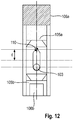
- Figure 12 shows an embodiment of the bolt 105 according to the invention as part of the first clutch half 100 and the clutch 300, with which the slip effect described above can be avoided even at low speeds.
- the bar 105 from Figure 12 defines an asymmetrical weight distribution towards one of the two force transmission elements 105a, 105b in both end positions.
- a thickening section 106a is formed at the end of the latch 105, on which the first force transmission element 105a is formed
- a recess section 106b is formed at the end of the latch 105, on which the second force transmission element 105b is formed.
- the thickening section 106a can also be formed as part of the first force transmission element 105a and the Cutout portion 106b may also be part of the second power transmission element 105b.
- the center of gravity 110 of the bolt 105 defined by the mass distribution is always relative to the axis of rotation, ie in particular in both End positions of the bolt 105 is located on one and the same side of the bolt 105 on which one of the two force transmission elements 105a, 105b is formed.
- the center of gravity 110 of the bolt 107 is always on the side of the first force transmission element 105a due to the thickening section 106a of the first force transmission element 105a and the recess section 106b of the second force transmission element 105b.
- d denotes the distance between the position of the center of gravity 110 with the asymmetrical mass distribution of the bolt 105 and the position of the center of gravity in the case of a bolt 105 with a symmetrical mass distribution.
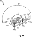
- the Figures 13 and 14 show an embodiment of the first coupling half 100 according to the invention with a bolt 105 with an asymmetrical mass distribution.
- the asymmetrical mass distribution of the bar 105 is achieved by the recess section 106b and openings at one end of the bar 105, on which the second force transmission element 105b is formed, and by a thickening section or a material thickening 106a at the other end of the bar 105, at which the first Power transmission element 105b is formed.
- configuration is the focus of the Bolt 105 relative to the axis defined by the centering mandrel 103 always on the side of the bolt 105 on which the thickening section 106a is formed.
- one or more of the following features can be implemented in an embodiment of the coupling 300 according to the invention in order to counteract the effect of the bolt 105 sliding off due to gravity.
- respective latching elements can be provided at the end positions or end stops of the guide of the latch 105, by means of which the latch 105 engages in both end positions.
- magnetic locking systems are particularly suitable for this.
- the bolt 105 can also be fixed by means of friction.
- a coulomb friction can be generated by a spring element which presses on the latch 105 transversely to the guide.
- the generation of viscous friction by grease lubrication of the bolt guide is particularly preferred. In this case, the pushing forces are essentially only speed-dependent.
- the clearance angle can also be reduced. With clearance angle values clearly below 180 °, the slipping described above no longer occurs, so that an additional fixation of the bolt 105 is not necessary.
Landscapes
- Engineering & Computer Science (AREA)
- General Engineering & Computer Science (AREA)
- Mechanical Engineering (AREA)
- Mechanical Operated Clutches (AREA)
- Quick-Acting Or Multi-Walled Pipe Joints (AREA)
Priority Applications (1)
| Application Number | Priority Date | Filing Date | Title |
|---|---|---|---|
| PL17716913T PL3449142T3 (pl) | 2016-04-28 | 2017-04-12 | Złącze do rozłącznego łączenia dwóch wałów |
Applications Claiming Priority (2)
| Application Number | Priority Date | Filing Date | Title |
|---|---|---|---|
| DE102016207246.3A DE102016207246B3 (de) | 2016-04-28 | 2016-04-28 | Kupplung zum lösbaren verbinden von zwei wellen |
| PCT/EP2017/058814 WO2017186499A1 (de) | 2016-04-28 | 2017-04-12 | Kupplung zum lösbaren verbinden von zwei wellen |
Publications (2)
| Publication Number | Publication Date |
|---|---|
| EP3449142A1 EP3449142A1 (de) | 2019-03-06 |
| EP3449142B1 true EP3449142B1 (de) | 2019-12-25 |
Family
ID=58537015
Family Applications (1)
| Application Number | Title | Priority Date | Filing Date |
|---|---|---|---|
| EP17716913.3A Active EP3449142B1 (de) | 2016-04-28 | 2017-04-12 | Kupplung zum lösbaren verbinden von zwei wellen |
Country Status (5)
| Country | Link |
|---|---|
| EP (1) | EP3449142B1 (pl) |
| CN (1) | CN109072984B (pl) |
| DE (1) | DE102016207246B3 (pl) |
| PL (1) | PL3449142T3 (pl) |
| WO (1) | WO2017186499A1 (pl) |
Family Cites Families (12)
| Publication number | Priority date | Publication date | Assignee | Title |
|---|---|---|---|---|
| DE907857C (de) * | 1951-11-06 | 1954-03-29 | Klaue Hermann | Schaltvorrichtung, insbesondere fuer Kraftwagengetriebe |
| US3280439A (en) * | 1964-04-16 | 1966-10-25 | Norco Inc | Mechanical coupling |
| US4172369A (en) * | 1978-03-13 | 1979-10-30 | Hayes Charles J | Flexible coupling |
| US4392759A (en) * | 1981-02-09 | 1983-07-12 | General Electric Company | Quick disconnect mechanism for shafts |
| DE3501262C1 (de) * | 1985-01-16 | 1986-07-17 | Jean Walterscheid Gmbh, 5204 Lohmar | In Offenstellung arretierbarer Ziehverschluss |
| FR2628488B1 (fr) * | 1988-03-14 | 1990-12-28 | Ecia Equip Composants Ind Auto | Attache rapide du type a baionnette perfectionnee |
| FR2673691A1 (fr) * | 1991-03-05 | 1992-09-11 | Europ Agence Spatiale | Dispositif d'accouplement mecanique separable. |
| DE4224736A1 (de) * | 1992-07-27 | 1994-02-03 | Luk Fahrzeug Hydraulik | Hydraulikmaschine |
| US5788473A (en) * | 1996-12-10 | 1998-08-04 | Ingersoll-Dresser Pump Company | Integral close coupling for a rotary gear pump |
| DE102004060222A1 (de) * | 2004-12-15 | 2006-06-29 | Netzsch-Mohnopumpen Gmbh | Exzenterschneckenpumpe in Kompaktbauweise |
| CN101858391A (zh) * | 2009-04-09 | 2010-10-13 | 鸿富锦精密工业(深圳)有限公司 | 连接装置 |
| DE102013215449A1 (de) * | 2013-08-06 | 2015-02-12 | Robert Bosch Gmbh | Kupplungseinrichtung für eine Dosierpumpe |
-
2016
- 2016-04-28 DE DE102016207246.3A patent/DE102016207246B3/de not_active Expired - Fee Related
-
2017
- 2017-04-12 EP EP17716913.3A patent/EP3449142B1/de active Active
- 2017-04-12 WO PCT/EP2017/058814 patent/WO2017186499A1/de not_active Ceased
- 2017-04-12 CN CN201780026195.9A patent/CN109072984B/zh active Active
- 2017-04-12 PL PL17716913T patent/PL3449142T3/pl unknown
Non-Patent Citations (1)
| Title |
|---|
| None * |
Also Published As
| Publication number | Publication date |
|---|---|
| CN109072984B (zh) | 2021-06-22 |
| CN109072984A (zh) | 2018-12-21 |
| DE102016207246B3 (de) | 2017-05-18 |
| WO2017186499A1 (de) | 2017-11-02 |
| PL3449142T3 (pl) | 2020-06-29 |
| EP3449142A1 (de) | 2019-03-06 |
Similar Documents
| Publication | Publication Date | Title |
|---|---|---|
| DE60207666T2 (de) | Riemenscheibe mit Einwegkupplung | |
| WO2003027538A1 (de) | Getriebe | |
| DE4409994A1 (de) | Verdrängerkolbenpumpe | |
| EP3472492A1 (de) | Planetengetriebe | |
| EP4659563A1 (de) | Werkzeugantriebseinheit für ein schneidmesser eines handgehaltenen arbeitsgeräts, sowie handgehaltenes arbeitsgerät mit der werkzeugantriebseinheit | |
| DE4122841C2 (de) | Motorstartergetriebe | |
| DE69626291T2 (de) | Verschlussvorrichtung für eine kupplungsverbindung | |
| WO1992009406A1 (de) | Handgeführtes kraftdrehwerkzeug | |
| DE2236832A1 (de) | Fliehkraftversteller zur aenderung des einspritzzeitpunktes bei kraftstoffeinspritzpumpen fuer dieselmotoren | |
| EP2769109B1 (de) | Verbindungseinrichtung und verfahren zu deren herstellung | |
| DE2116547A1 (de) | Drehzahlveränderliche Antriebsübertragungsvorrichtung | |
| DE102016207246B3 (de) | Kupplung zum lösbaren verbinden von zwei wellen | |
| DE3854500T2 (de) | Mechanische übertragung. | |
| WO2012139674A1 (de) | Getriebe | |
| EP3042104B1 (de) | Stufenloses getriebe | |
| EP3211230A1 (de) | Axialkolbenmaschine, insbesondere axialkolbenpumpe | |
| DE102016103268B4 (de) | Bodenverdichter | |
| DE4339029C2 (de) | Flüssigkeitsringmaschine | |
| DE3808769C2 (pl) | ||
| EP4474644A1 (de) | Peristaltikpumpe | |
| DE102004022362B4 (de) | Schaltbare mehrstufige Ölpumpe | |
| DE2208088A1 (de) | Keilriemen Übertragungsvorrichtung zur stufenlosen Änderung des Getriebe Verhältnisses | |
| WO2005018072A1 (de) | Gehäuseteil eines antriebs und gegenstück | |
| DE2017861A1 (de) | Einrichtung zur Verhinderung von totem Spiel bzw. Lose bei Getriebeanordnungen | |
| DE3312310C2 (pl) |
Legal Events
| Date | Code | Title | Description |
|---|---|---|---|
| STAA | Information on the status of an ep patent application or granted ep patent |
Free format text: STATUS: UNKNOWN |
|
| STAA | Information on the status of an ep patent application or granted ep patent |
Free format text: STATUS: THE INTERNATIONAL PUBLICATION HAS BEEN MADE |
|
| PUAI | Public reference made under article 153(3) epc to a published international application that has entered the european phase |
Free format text: ORIGINAL CODE: 0009012 |
|
| STAA | Information on the status of an ep patent application or granted ep patent |
Free format text: STATUS: REQUEST FOR EXAMINATION WAS MADE |
|
| 17P | Request for examination filed |
Effective date: 20181128 |
|
| AK | Designated contracting states |
Kind code of ref document: A1 Designated state(s): AL AT BE BG CH CY CZ DE DK EE ES FI FR GB GR HR HU IE IS IT LI LT LU LV MC MK MT NL NO PL PT RO RS SE SI SK SM TR |
|
| AX | Request for extension of the european patent |
Extension state: BA ME |
|
| DAV | Request for validation of the european patent (deleted) | ||
| DAX | Request for extension of the european patent (deleted) | ||
| GRAP | Despatch of communication of intention to grant a patent |
Free format text: ORIGINAL CODE: EPIDOSNIGR1 |
|
| STAA | Information on the status of an ep patent application or granted ep patent |
Free format text: STATUS: GRANT OF PATENT IS INTENDED |
|
| INTG | Intention to grant announced |
Effective date: 20190903 |
|
| GRAS | Grant fee paid |
Free format text: ORIGINAL CODE: EPIDOSNIGR3 |
|
| GRAA | (expected) grant |
Free format text: ORIGINAL CODE: 0009210 |
|
| STAA | Information on the status of an ep patent application or granted ep patent |
Free format text: STATUS: THE PATENT HAS BEEN GRANTED |
|
| AK | Designated contracting states |
Kind code of ref document: B1 Designated state(s): AL AT BE BG CH CY CZ DE DK EE ES FI FR GB GR HR HU IE IS IT LI LT LU LV MC MK MT NL NO PL PT RO RS SE SI SK SM TR |
|
| REG | Reference to a national code |
Ref country code: GB Ref legal event code: FG4D Free format text: NOT ENGLISH |
|
| REG | Reference to a national code |
Ref country code: CH Ref legal event code: EP |
|
| REG | Reference to a national code |
Ref country code: DE Ref legal event code: R096 Ref document number: 502017003295 Country of ref document: DE |
|
| REG | Reference to a national code |
Ref country code: AT Ref legal event code: REF Ref document number: 1217446 Country of ref document: AT Kind code of ref document: T Effective date: 20200115 |
|
| REG | Reference to a national code |
Ref country code: IE Ref legal event code: FG4D Free format text: LANGUAGE OF EP DOCUMENT: GERMAN |
|
| REG | Reference to a national code |
Ref country code: NL Ref legal event code: MP Effective date: 20191225 |
|
| PG25 | Lapsed in a contracting state [announced via postgrant information from national office to epo] |
Ref country code: BG Free format text: LAPSE BECAUSE OF FAILURE TO SUBMIT A TRANSLATION OF THE DESCRIPTION OR TO PAY THE FEE WITHIN THE PRESCRIBED TIME-LIMIT Effective date: 20200325 Ref country code: FI Free format text: LAPSE BECAUSE OF FAILURE TO SUBMIT A TRANSLATION OF THE DESCRIPTION OR TO PAY THE FEE WITHIN THE PRESCRIBED TIME-LIMIT Effective date: 20191225 Ref country code: GR Free format text: LAPSE BECAUSE OF FAILURE TO SUBMIT A TRANSLATION OF THE DESCRIPTION OR TO PAY THE FEE WITHIN THE PRESCRIBED TIME-LIMIT Effective date: 20200326 Ref country code: LT Free format text: LAPSE BECAUSE OF FAILURE TO SUBMIT A TRANSLATION OF THE DESCRIPTION OR TO PAY THE FEE WITHIN THE PRESCRIBED TIME-LIMIT Effective date: 20191225 Ref country code: NO Free format text: LAPSE BECAUSE OF FAILURE TO SUBMIT A TRANSLATION OF THE DESCRIPTION OR TO PAY THE FEE WITHIN THE PRESCRIBED TIME-LIMIT Effective date: 20200325 Ref country code: LV Free format text: LAPSE BECAUSE OF FAILURE TO SUBMIT A TRANSLATION OF THE DESCRIPTION OR TO PAY THE FEE WITHIN THE PRESCRIBED TIME-LIMIT Effective date: 20191225 Ref country code: SE Free format text: LAPSE BECAUSE OF FAILURE TO SUBMIT A TRANSLATION OF THE DESCRIPTION OR TO PAY THE FEE WITHIN THE PRESCRIBED TIME-LIMIT Effective date: 20191225 |
|
| REG | Reference to a national code |
Ref country code: LT Ref legal event code: MG4D |
|
| PG25 | Lapsed in a contracting state [announced via postgrant information from national office to epo] |
Ref country code: HR Free format text: LAPSE BECAUSE OF FAILURE TO SUBMIT A TRANSLATION OF THE DESCRIPTION OR TO PAY THE FEE WITHIN THE PRESCRIBED TIME-LIMIT Effective date: 20191225 Ref country code: RS Free format text: LAPSE BECAUSE OF FAILURE TO SUBMIT A TRANSLATION OF THE DESCRIPTION OR TO PAY THE FEE WITHIN THE PRESCRIBED TIME-LIMIT Effective date: 20191225 |
|
| PG25 | Lapsed in a contracting state [announced via postgrant information from national office to epo] |
Ref country code: AL Free format text: LAPSE BECAUSE OF FAILURE TO SUBMIT A TRANSLATION OF THE DESCRIPTION OR TO PAY THE FEE WITHIN THE PRESCRIBED TIME-LIMIT Effective date: 20191225 |
|
| PG25 | Lapsed in a contracting state [announced via postgrant information from national office to epo] |
Ref country code: NL Free format text: LAPSE BECAUSE OF FAILURE TO SUBMIT A TRANSLATION OF THE DESCRIPTION OR TO PAY THE FEE WITHIN THE PRESCRIBED TIME-LIMIT Effective date: 20191225 Ref country code: RO Free format text: LAPSE BECAUSE OF FAILURE TO SUBMIT A TRANSLATION OF THE DESCRIPTION OR TO PAY THE FEE WITHIN THE PRESCRIBED TIME-LIMIT Effective date: 20191225 Ref country code: PT Free format text: LAPSE BECAUSE OF FAILURE TO SUBMIT A TRANSLATION OF THE DESCRIPTION OR TO PAY THE FEE WITHIN THE PRESCRIBED TIME-LIMIT Effective date: 20200520 Ref country code: CZ Free format text: LAPSE BECAUSE OF FAILURE TO SUBMIT A TRANSLATION OF THE DESCRIPTION OR TO PAY THE FEE WITHIN THE PRESCRIBED TIME-LIMIT Effective date: 20191225 Ref country code: EE Free format text: LAPSE BECAUSE OF FAILURE TO SUBMIT A TRANSLATION OF THE DESCRIPTION OR TO PAY THE FEE WITHIN THE PRESCRIBED TIME-LIMIT Effective date: 20191225 |
|
| PG25 | Lapsed in a contracting state [announced via postgrant information from national office to epo] |
Ref country code: IS Free format text: LAPSE BECAUSE OF FAILURE TO SUBMIT A TRANSLATION OF THE DESCRIPTION OR TO PAY THE FEE WITHIN THE PRESCRIBED TIME-LIMIT Effective date: 20200425 Ref country code: SK Free format text: LAPSE BECAUSE OF FAILURE TO SUBMIT A TRANSLATION OF THE DESCRIPTION OR TO PAY THE FEE WITHIN THE PRESCRIBED TIME-LIMIT Effective date: 20191225 Ref country code: SM Free format text: LAPSE BECAUSE OF FAILURE TO SUBMIT A TRANSLATION OF THE DESCRIPTION OR TO PAY THE FEE WITHIN THE PRESCRIBED TIME-LIMIT Effective date: 20191225 |
|
| REG | Reference to a national code |
Ref country code: DE Ref legal event code: R097 Ref document number: 502017003295 Country of ref document: DE |
|
| PG25 | Lapsed in a contracting state [announced via postgrant information from national office to epo] |
Ref country code: ES Free format text: LAPSE BECAUSE OF FAILURE TO SUBMIT A TRANSLATION OF THE DESCRIPTION OR TO PAY THE FEE WITHIN THE PRESCRIBED TIME-LIMIT Effective date: 20191225 Ref country code: DK Free format text: LAPSE BECAUSE OF FAILURE TO SUBMIT A TRANSLATION OF THE DESCRIPTION OR TO PAY THE FEE WITHIN THE PRESCRIBED TIME-LIMIT Effective date: 20191225 |
|
| PLBE | No opposition filed within time limit |
Free format text: ORIGINAL CODE: 0009261 |
|
| STAA | Information on the status of an ep patent application or granted ep patent |
Free format text: STATUS: NO OPPOSITION FILED WITHIN TIME LIMIT |
|
| PG25 | Lapsed in a contracting state [announced via postgrant information from national office to epo] |
Ref country code: SI Free format text: LAPSE BECAUSE OF FAILURE TO SUBMIT A TRANSLATION OF THE DESCRIPTION OR TO PAY THE FEE WITHIN THE PRESCRIBED TIME-LIMIT Effective date: 20191225 Ref country code: MC Free format text: LAPSE BECAUSE OF FAILURE TO SUBMIT A TRANSLATION OF THE DESCRIPTION OR TO PAY THE FEE WITHIN THE PRESCRIBED TIME-LIMIT Effective date: 20191225 |
|
| REG | Reference to a national code |
Ref country code: CH Ref legal event code: PL |
|
| 26N | No opposition filed |
Effective date: 20200928 |
|
| PG25 | Lapsed in a contracting state [announced via postgrant information from national office to epo] |
Ref country code: LI Free format text: LAPSE BECAUSE OF NON-PAYMENT OF DUE FEES Effective date: 20200430 Ref country code: CH Free format text: LAPSE BECAUSE OF NON-PAYMENT OF DUE FEES Effective date: 20200430 Ref country code: LU Free format text: LAPSE BECAUSE OF NON-PAYMENT OF DUE FEES Effective date: 20200412 Ref country code: FR Free format text: LAPSE BECAUSE OF NON-PAYMENT OF DUE FEES Effective date: 20200430 Ref country code: IT Free format text: LAPSE BECAUSE OF FAILURE TO SUBMIT A TRANSLATION OF THE DESCRIPTION OR TO PAY THE FEE WITHIN THE PRESCRIBED TIME-LIMIT Effective date: 20191225 |
|
| REG | Reference to a national code |
Ref country code: BE Ref legal event code: MM Effective date: 20200430 |
|
| PG25 | Lapsed in a contracting state [announced via postgrant information from national office to epo] |
Ref country code: BE Free format text: LAPSE BECAUSE OF NON-PAYMENT OF DUE FEES Effective date: 20200430 |
|
| PG25 | Lapsed in a contracting state [announced via postgrant information from national office to epo] |
Ref country code: IE Free format text: LAPSE BECAUSE OF NON-PAYMENT OF DUE FEES Effective date: 20200412 |
|
| GBPC | Gb: european patent ceased through non-payment of renewal fee |
Effective date: 20210412 |
|
| PG25 | Lapsed in a contracting state [announced via postgrant information from national office to epo] |
Ref country code: GB Free format text: LAPSE BECAUSE OF NON-PAYMENT OF DUE FEES Effective date: 20210412 |
|
| PG25 | Lapsed in a contracting state [announced via postgrant information from national office to epo] |
Ref country code: TR Free format text: LAPSE BECAUSE OF FAILURE TO SUBMIT A TRANSLATION OF THE DESCRIPTION OR TO PAY THE FEE WITHIN THE PRESCRIBED TIME-LIMIT Effective date: 20191225 Ref country code: MT Free format text: LAPSE BECAUSE OF FAILURE TO SUBMIT A TRANSLATION OF THE DESCRIPTION OR TO PAY THE FEE WITHIN THE PRESCRIBED TIME-LIMIT Effective date: 20191225 Ref country code: CY Free format text: LAPSE BECAUSE OF FAILURE TO SUBMIT A TRANSLATION OF THE DESCRIPTION OR TO PAY THE FEE WITHIN THE PRESCRIBED TIME-LIMIT Effective date: 20191225 |
|
| PG25 | Lapsed in a contracting state [announced via postgrant information from national office to epo] |
Ref country code: MK Free format text: LAPSE BECAUSE OF FAILURE TO SUBMIT A TRANSLATION OF THE DESCRIPTION OR TO PAY THE FEE WITHIN THE PRESCRIBED TIME-LIMIT Effective date: 20191225 |
|
| REG | Reference to a national code |
Ref country code: DE Ref legal event code: R084 Ref document number: 502017003295 Country of ref document: DE |
|
| REG | Reference to a national code |
Ref country code: AT Ref legal event code: MM01 Ref document number: 1217446 Country of ref document: AT Kind code of ref document: T Effective date: 20220412 |
|
| PG25 | Lapsed in a contracting state [announced via postgrant information from national office to epo] |
Ref country code: AT Free format text: LAPSE BECAUSE OF NON-PAYMENT OF DUE FEES Effective date: 20220412 |
|
| PGFP | Annual fee paid to national office [announced via postgrant information from national office to epo] |
Ref country code: PL Payment date: 20240402 Year of fee payment: 8 |
|
| PGFP | Annual fee paid to national office [announced via postgrant information from national office to epo] |
Ref country code: DE Payment date: 20250430 Year of fee payment: 9 |