EP3448485B1 - Patientenschnittstelle - Google Patents
Patientenschnittstelle Download PDFInfo
- Publication number
- EP3448485B1 EP3448485B1 EP17788434.3A EP17788434A EP3448485B1 EP 3448485 B1 EP3448485 B1 EP 3448485B1 EP 17788434 A EP17788434 A EP 17788434A EP 3448485 B1 EP3448485 B1 EP 3448485B1
- Authority
- EP
- European Patent Office
- Prior art keywords
- patient
- seal
- forming structure
- patient interface
- plenum chamber
- Prior art date
- Legal status (The legal status is an assumption and is not a legal conclusion. Google has not performed a legal analysis and makes no representation as to the accuracy of the status listed.)
- Active
Links
- 239000003570 air Substances 0.000 claims description 133
- 238000007789 sealing Methods 0.000 claims description 71
- 239000000463 material Substances 0.000 claims description 67
- 230000003019 stabilising effect Effects 0.000 claims description 66
- 238000002560 therapeutic procedure Methods 0.000 claims description 47
- 230000029058 respiratory gaseous exchange Effects 0.000 claims description 46
- NOQGZXFMHARMLW-UHFFFAOYSA-N Daminozide Chemical compound CN(C)NC(=O)CCC(O)=O NOQGZXFMHARMLW-UHFFFAOYSA-N 0.000 claims description 41
- 230000000241 respiratory effect Effects 0.000 claims description 41
- 230000007958 sleep Effects 0.000 claims description 23
- 238000012384 transportation and delivery Methods 0.000 claims description 23
- 239000012080 ambient air Substances 0.000 claims description 20
- 230000033001 locomotion Effects 0.000 claims description 18
- 230000001225 therapeutic effect Effects 0.000 claims description 13
- 229920001296 polysiloxane Polymers 0.000 claims description 10
- 210000000103 occipital bone Anatomy 0.000 claims description 8
- 239000006260 foam Substances 0.000 claims description 7
- 210000003455 parietal bone Anatomy 0.000 claims description 7
- 239000013013 elastic material Substances 0.000 claims description 6
- 229920001084 poly(chloroprene) Polymers 0.000 claims description 4
- 239000000126 substance Substances 0.000 claims description 4
- 239000004753 textile Substances 0.000 claims description 4
- 238000005516 engineering process Methods 0.000 description 184
- 210000001331 nose Anatomy 0.000 description 59
- 210000003128 head Anatomy 0.000 description 51
- 210000000088 lip Anatomy 0.000 description 44
- 239000007789 gas Substances 0.000 description 43
- 210000004379 membrane Anatomy 0.000 description 43
- 239000012528 membrane Substances 0.000 description 43
- 238000009423 ventilation Methods 0.000 description 32
- 239000010410 layer Substances 0.000 description 30
- XLYOFNOQVPJJNP-UHFFFAOYSA-N water Substances O XLYOFNOQVPJJNP-UHFFFAOYSA-N 0.000 description 25
- 239000013598 vector Substances 0.000 description 24
- 238000011282 treatment Methods 0.000 description 23
- 210000000845 cartilage Anatomy 0.000 description 20
- 230000003434 inspiratory effect Effects 0.000 description 18
- 238000000034 method Methods 0.000 description 18
- 210000000214 mouth Anatomy 0.000 description 18
- CURLTUGMZLYLDI-UHFFFAOYSA-N Carbon dioxide Chemical compound O=C=O CURLTUGMZLYLDI-UHFFFAOYSA-N 0.000 description 16
- 230000036961 partial effect Effects 0.000 description 16
- 241000083547 Columella Species 0.000 description 14
- 238000010438 heat treatment Methods 0.000 description 14
- 210000004373 mandible Anatomy 0.000 description 13
- 210000003491 skin Anatomy 0.000 description 13
- 229910052760 oxygen Inorganic materials 0.000 description 12
- 208000023504 respiratory system disease Diseases 0.000 description 12
- 208000004756 Respiratory Insufficiency Diseases 0.000 description 11
- 229910002092 carbon dioxide Inorganic materials 0.000 description 11
- 208000037265 diseases, disorders, signs and symptoms Diseases 0.000 description 11
- 210000004072 lung Anatomy 0.000 description 11
- 210000002050 maxilla Anatomy 0.000 description 11
- 201000004193 respiratory failure Diseases 0.000 description 11
- 206010008501 Cheyne-Stokes respiration Diseases 0.000 description 10
- 210000000988 bone and bone Anatomy 0.000 description 10
- 208000035475 disorder Diseases 0.000 description 10
- 210000003928 nasal cavity Anatomy 0.000 description 10
- 229920002379 silicone rubber Polymers 0.000 description 10
- QVGXLLKOCUKJST-UHFFFAOYSA-N atomic oxygen Chemical compound [O] QVGXLLKOCUKJST-UHFFFAOYSA-N 0.000 description 9
- 230000006835 compression Effects 0.000 description 9
- 238000007906 compression Methods 0.000 description 9
- 210000001508 eye Anatomy 0.000 description 9
- 210000001061 forehead Anatomy 0.000 description 9
- 208000018360 neuromuscular disease Diseases 0.000 description 9
- 239000001301 oxygen Substances 0.000 description 9
- 210000003205 muscle Anatomy 0.000 description 8
- 230000009467 reduction Effects 0.000 description 8
- 210000003625 skull Anatomy 0.000 description 8
- 238000011144 upstream manufacturing Methods 0.000 description 8
- 206010021079 Hypopnoea Diseases 0.000 description 7
- 208000030984 MIRAGE syndrome Diseases 0.000 description 7
- 239000000853 adhesive Substances 0.000 description 7
- 230000001070 adhesive effect Effects 0.000 description 7
- 210000003484 anatomy Anatomy 0.000 description 7
- 230000008859 change Effects 0.000 description 7
- 238000004891 communication Methods 0.000 description 7
- 238000011513 continuous positive airway pressure therapy Methods 0.000 description 7
- 238000013461 design Methods 0.000 description 7
- 238000003745 diagnosis Methods 0.000 description 7
- 230000000694 effects Effects 0.000 description 7
- 230000001815 facial effect Effects 0.000 description 7
- 210000000537 nasal bone Anatomy 0.000 description 7
- 208000001797 obstructive sleep apnea Diseases 0.000 description 7
- TVLSRXXIMLFWEO-UHFFFAOYSA-N prochloraz Chemical compound C1=CN=CN1C(=O)N(CCC)CCOC1=C(Cl)C=C(Cl)C=C1Cl TVLSRXXIMLFWEO-UHFFFAOYSA-N 0.000 description 7
- 210000002345 respiratory system Anatomy 0.000 description 7
- 208000006545 Chronic Obstructive Pulmonary Disease Diseases 0.000 description 6
- 208000008784 apnea Diseases 0.000 description 6
- 238000005452 bending Methods 0.000 description 6
- 238000004519 manufacturing process Methods 0.000 description 6
- 210000003800 pharynx Anatomy 0.000 description 6
- 230000008569 process Effects 0.000 description 6
- 210000004872 soft tissue Anatomy 0.000 description 6
- 230000000087 stabilizing effect Effects 0.000 description 6
- 210000003437 trachea Anatomy 0.000 description 6
- 208000000059 Dyspnea Diseases 0.000 description 5
- 206010013975 Dyspnoeas Diseases 0.000 description 5
- 239000004944 Liquid Silicone Rubber Substances 0.000 description 5
- 206010067775 Upper airway obstruction Diseases 0.000 description 5
- 210000003123 bronchiole Anatomy 0.000 description 5
- 210000000867 larynx Anatomy 0.000 description 5
- 238000002644 respiratory therapy Methods 0.000 description 5
- 210000000621 bronchi Anatomy 0.000 description 4
- 210000003414 extremity Anatomy 0.000 description 4
- 239000004744 fabric Substances 0.000 description 4
- 239000012530 fluid Substances 0.000 description 4
- 210000002454 frontal bone Anatomy 0.000 description 4
- 230000006870 function Effects 0.000 description 4
- 208000000122 hyperventilation Diseases 0.000 description 4
- 210000002184 nasal cartilage Anatomy 0.000 description 4
- 230000002265 prevention Effects 0.000 description 4
- 239000002356 single layer Substances 0.000 description 4
- 208000024891 symptom Diseases 0.000 description 4
- 229920002725 thermoplastic elastomer Polymers 0.000 description 4
- 210000002105 tongue Anatomy 0.000 description 4
- 206010003497 Asphyxia Diseases 0.000 description 3
- 206010019233 Headaches Diseases 0.000 description 3
- 230000008901 benefit Effects 0.000 description 3
- 239000001569 carbon dioxide Substances 0.000 description 3
- 238000004140 cleaning Methods 0.000 description 3
- 230000006735 deficit Effects 0.000 description 3
- 230000001419 dependent effect Effects 0.000 description 3
- 238000006073 displacement reaction Methods 0.000 description 3
- 229920001971 elastomer Polymers 0.000 description 3
- 231100000869 headache Toxicity 0.000 description 3
- 230000036541 health Effects 0.000 description 3
- 210000003026 hypopharynx Anatomy 0.000 description 3
- 239000007788 liquid Substances 0.000 description 3
- 230000014759 maintenance of location Effects 0.000 description 3
- 230000013011 mating Effects 0.000 description 3
- 230000007246 mechanism Effects 0.000 description 3
- 210000000492 nasalseptum Anatomy 0.000 description 3
- 210000001989 nasopharynx Anatomy 0.000 description 3
- 229920000515 polycarbonate Polymers 0.000 description 3
- 239000004417 polycarbonate Substances 0.000 description 3
- 230000000750 progressive effect Effects 0.000 description 3
- 230000003252 repetitive effect Effects 0.000 description 3
- 210000001584 soft palate Anatomy 0.000 description 3
- 230000002269 spontaneous effect Effects 0.000 description 3
- 239000003351 stiffener Substances 0.000 description 3
- 230000000153 supplemental effect Effects 0.000 description 3
- 210000000115 thoracic cavity Anatomy 0.000 description 3
- 210000000779 thoracic wall Anatomy 0.000 description 3
- 239000012780 transparent material Substances 0.000 description 3
- 230000001960 triggered effect Effects 0.000 description 3
- 230000003519 ventilatory effect Effects 0.000 description 3
- 210000001260 vocal cord Anatomy 0.000 description 3
- 208000007590 Disorders of Excessive Somnolence Diseases 0.000 description 2
- 206010013801 Duchenne Muscular Dystrophy Diseases 0.000 description 2
- 208000008589 Obesity Diseases 0.000 description 2
- 206010041349 Somnolence Diseases 0.000 description 2
- 239000004411 aluminium Substances 0.000 description 2
- 229910052782 aluminium Inorganic materials 0.000 description 2
- XAGFODPZIPBFFR-UHFFFAOYSA-N aluminium Chemical compound [Al] XAGFODPZIPBFFR-UHFFFAOYSA-N 0.000 description 2
- 206010002026 amyotrophic lateral sclerosis Diseases 0.000 description 2
- 230000037007 arousal Effects 0.000 description 2
- 230000009286 beneficial effect Effects 0.000 description 2
- 239000000560 biocompatible material Substances 0.000 description 2
- IISBACLAFKSPIT-UHFFFAOYSA-N bisphenol A Chemical compound C=1C=C(O)C=CC=1C(C)(C)C1=CC=C(O)C=C1 IISBACLAFKSPIT-UHFFFAOYSA-N 0.000 description 2
- 239000008280 blood Substances 0.000 description 2
- 210000004369 blood Anatomy 0.000 description 2
- 210000000038 chest Anatomy 0.000 description 2
- 230000001684 chronic effect Effects 0.000 description 2
- 230000000295 complement effect Effects 0.000 description 2
- 239000004020 conductor Substances 0.000 description 2
- 238000013523 data management Methods 0.000 description 2
- 238000001514 detection method Methods 0.000 description 2
- 238000001035 drying Methods 0.000 description 2
- 230000009977 dual effect Effects 0.000 description 2
- 239000000806 elastomer Substances 0.000 description 2
- 210000002532 foramen magnum Anatomy 0.000 description 2
- 210000002216 heart Anatomy 0.000 description 2
- 238000007373 indentation Methods 0.000 description 2
- 230000000977 initiatory effect Effects 0.000 description 2
- 210000001847 jaw Anatomy 0.000 description 2
- 230000003340 mental effect Effects 0.000 description 2
- 238000004377 microelectronic Methods 0.000 description 2
- 238000012544 monitoring process Methods 0.000 description 2
- 235000020824 obesity Nutrition 0.000 description 2
- 210000003300 oropharynx Anatomy 0.000 description 2
- 238000006213 oxygenation reaction Methods 0.000 description 2
- 230000007170 pathology Effects 0.000 description 2
- 208000037821 progressive disease Diseases 0.000 description 2
- 230000002829 reductive effect Effects 0.000 description 2
- 230000004044 response Effects 0.000 description 2
- 239000004945 silicone rubber Substances 0.000 description 2
- 230000009182 swimming Effects 0.000 description 2
- 210000003582 temporal bone Anatomy 0.000 description 2
- 210000001738 temporomandibular joint Anatomy 0.000 description 2
- 238000010998 test method Methods 0.000 description 2
- 238000012360 testing method Methods 0.000 description 2
- 229920001169 thermoplastic Polymers 0.000 description 2
- 238000012546 transfer Methods 0.000 description 2
- 210000001944 turbinate Anatomy 0.000 description 2
- ORILYTVJVMAKLC-UHFFFAOYSA-N Adamantane Natural products C1C(C2)CC3CC1CC2C3 ORILYTVJVMAKLC-UHFFFAOYSA-N 0.000 description 1
- 241000024188 Andala Species 0.000 description 1
- 206010006458 Bronchitis chronic Diseases 0.000 description 1
- BVKZGUZCCUSVTD-UHFFFAOYSA-L Carbonate Chemical compound [O-]C([O-])=O BVKZGUZCCUSVTD-UHFFFAOYSA-L 0.000 description 1
- 208000024172 Cardiovascular disease Diseases 0.000 description 1
- 208000003417 Central Sleep Apnea Diseases 0.000 description 1
- 206010011224 Cough Diseases 0.000 description 1
- 208000019505 Deglutition disease Diseases 0.000 description 1
- 206010014561 Emphysema Diseases 0.000 description 1
- 230000005355 Hall effect Effects 0.000 description 1
- 241000282412 Homo Species 0.000 description 1
- 206010020591 Hypercapnia Diseases 0.000 description 1
- 206010021133 Hypoventilation Diseases 0.000 description 1
- 206010021143 Hypoxia Diseases 0.000 description 1
- 206010023506 Kyphoscoliosis Diseases 0.000 description 1
- 206010024971 Lower respiratory tract infections Diseases 0.000 description 1
- 208000019693 Lung disease Diseases 0.000 description 1
- 241000121185 Monodon monoceros Species 0.000 description 1
- 206010027940 Mood altered Diseases 0.000 description 1
- 208000001705 Mouth breathing Diseases 0.000 description 1
- 241000208125 Nicotiana Species 0.000 description 1
- 235000002637 Nicotiana tabacum Nutrition 0.000 description 1
- 206010073310 Occupational exposures Diseases 0.000 description 1
- 206010030124 Oedema peripheral Diseases 0.000 description 1
- 206010031123 Orthopnoea Diseases 0.000 description 1
- 206010033307 Overweight Diseases 0.000 description 1
- 239000004743 Polypropylene Substances 0.000 description 1
- 206010062519 Poor quality sleep Diseases 0.000 description 1
- 206010036790 Productive cough Diseases 0.000 description 1
- 206010070833 Respiratory muscle weakness Diseases 0.000 description 1
- 241001016288 Sesamoides Species 0.000 description 1
- 208000032140 Sleepiness Diseases 0.000 description 1
- 206010041235 Snoring Diseases 0.000 description 1
- 229910000831 Steel Inorganic materials 0.000 description 1
- 241000287181 Sturnus vulgaris Species 0.000 description 1
- 241000746998 Tragus Species 0.000 description 1
- 229920004482 WACKER® Polymers 0.000 description 1
- 208000027418 Wounds and injury Diseases 0.000 description 1
- 210000000683 abdominal cavity Anatomy 0.000 description 1
- 230000002159 abnormal effect Effects 0.000 description 1
- 230000005534 acoustic noise Effects 0.000 description 1
- 230000009471 action Effects 0.000 description 1
- 230000003044 adaptive effect Effects 0.000 description 1
- 210000000577 adipose tissue Anatomy 0.000 description 1
- 238000003915 air pollution Methods 0.000 description 1
- 229940124326 anaesthetic agent Drugs 0.000 description 1
- 230000003444 anaesthetic effect Effects 0.000 description 1
- 238000004458 analytical method Methods 0.000 description 1
- 230000000844 anti-bacterial effect Effects 0.000 description 1
- 230000004596 appetite loss Effects 0.000 description 1
- 230000006399 behavior Effects 0.000 description 1
- 229940106691 bisphenol a Drugs 0.000 description 1
- 230000006931 brain damage Effects 0.000 description 1
- 231100000874 brain damage Toxicity 0.000 description 1
- 208000029028 brain injury Diseases 0.000 description 1
- 206010006451 bronchitis Diseases 0.000 description 1
- 210000005252 bulbus oculi Anatomy 0.000 description 1
- 230000002612 cardiopulmonary effect Effects 0.000 description 1
- 208000007451 chronic bronchitis Diseases 0.000 description 1
- 208000013116 chronic cough Diseases 0.000 description 1
- 239000002131 composite material Substances 0.000 description 1
- 238000004590 computer program Methods 0.000 description 1
- 238000010276 construction Methods 0.000 description 1
- 230000008878 coupling Effects 0.000 description 1
- 238000010168 coupling process Methods 0.000 description 1
- 238000005859 coupling reaction Methods 0.000 description 1
- 230000006378 damage Effects 0.000 description 1
- 230000003247 decreasing effect Effects 0.000 description 1
- 230000007547 defect Effects 0.000 description 1
- 230000000994 depressogenic effect Effects 0.000 description 1
- 238000010586 diagram Methods 0.000 description 1
- 238000007599 discharging Methods 0.000 description 1
- 201000010099 disease Diseases 0.000 description 1
- 238000002224 dissection Methods 0.000 description 1
- 230000009189 diving Effects 0.000 description 1
- 230000005489 elastic deformation Effects 0.000 description 1
- 238000002565 electrocardiography Methods 0.000 description 1
- 238000000537 electroencephalography Methods 0.000 description 1
- 238000002567 electromyography Methods 0.000 description 1
- 210000002615 epidermis Anatomy 0.000 description 1
- 210000002409 epiglottis Anatomy 0.000 description 1
- 210000000887 face Anatomy 0.000 description 1
- 206010016256 fatigue Diseases 0.000 description 1
- 238000001914 filtration Methods 0.000 description 1
- 230000002068 genetic effect Effects 0.000 description 1
- 210000001983 hard palate Anatomy 0.000 description 1
- 201000000615 hard palate cancer Diseases 0.000 description 1
- 230000007954 hypoxia Effects 0.000 description 1
- 238000003780 insertion Methods 0.000 description 1
- 230000037431 insertion Effects 0.000 description 1
- 238000005304 joining Methods 0.000 description 1
- 230000000670 limiting effect Effects 0.000 description 1
- 230000007774 longterm Effects 0.000 description 1
- 235000021266 loss of appetite Nutrition 0.000 description 1
- 208000019017 loss of appetite Diseases 0.000 description 1
- 210000001699 lower leg Anatomy 0.000 description 1
- 208000023463 mandibuloacral dysplasia Diseases 0.000 description 1
- 238000005259 measurement Methods 0.000 description 1
- 230000010534 mechanism of action Effects 0.000 description 1
- 229910052751 metal Inorganic materials 0.000 description 1
- 239000002184 metal Substances 0.000 description 1
- 238000000120 microwave digestion Methods 0.000 description 1
- 239000000203 mixture Substances 0.000 description 1
- 230000007510 mood change Effects 0.000 description 1
- 208000001022 morbid obesity Diseases 0.000 description 1
- 230000003387 muscular Effects 0.000 description 1
- 201000006938 muscular dystrophy Diseases 0.000 description 1
- 230000003274 myotonic effect Effects 0.000 description 1
- 210000002850 nasal mucosa Anatomy 0.000 description 1
- 210000005036 nerve Anatomy 0.000 description 1
- 230000000414 obstructive effect Effects 0.000 description 1
- 231100000675 occupational exposure Toxicity 0.000 description 1
- 210000000056 organ Anatomy 0.000 description 1
- 208000012144 orthopnea Diseases 0.000 description 1
- 210000003254 palate Anatomy 0.000 description 1
- 230000001936 parietal effect Effects 0.000 description 1
- 239000004033 plastic Substances 0.000 description 1
- 229920003023 plastic Polymers 0.000 description 1
- -1 polypropylene Polymers 0.000 description 1
- 229920001155 polypropylene Polymers 0.000 description 1
- 230000003334 potential effect Effects 0.000 description 1
- 239000012858 resilient material Substances 0.000 description 1
- 210000003019 respiratory muscle Anatomy 0.000 description 1
- 230000036412 respiratory physiology Effects 0.000 description 1
- 230000000284 resting effect Effects 0.000 description 1
- 230000000452 restraining effect Effects 0.000 description 1
- 230000001020 rhythmical effect Effects 0.000 description 1
- 210000000614 rib Anatomy 0.000 description 1
- 238000005096 rolling process Methods 0.000 description 1
- 239000005060 rubber Substances 0.000 description 1
- 206010039722 scoliosis Diseases 0.000 description 1
- 230000035945 sensitivity Effects 0.000 description 1
- 208000013220 shortness of breath Diseases 0.000 description 1
- 229920000260 silastic Polymers 0.000 description 1
- 201000002859 sleep apnea Diseases 0.000 description 1
- 230000003860 sleep quality Effects 0.000 description 1
- 238000010321 sleep therapy Methods 0.000 description 1
- 230000037321 sleepiness Effects 0.000 description 1
- 230000000391 smoking effect Effects 0.000 description 1
- 208000024794 sputum Diseases 0.000 description 1
- 210000003802 sputum Anatomy 0.000 description 1
- 230000003068 static effect Effects 0.000 description 1
- 239000010959 steel Substances 0.000 description 1
- 238000003860 storage Methods 0.000 description 1
- 230000009747 swallowing Effects 0.000 description 1
- 210000004243 sweat Anatomy 0.000 description 1
- 230000002889 sympathetic effect Effects 0.000 description 1
- 208000011580 syndromic disease Diseases 0.000 description 1
- 229920003051 synthetic elastomer Polymers 0.000 description 1
- 239000005061 synthetic rubber Substances 0.000 description 1
- 230000002123 temporal effect Effects 0.000 description 1
- 239000004416 thermosoftening plastic Substances 0.000 description 1
- 210000001519 tissue Anatomy 0.000 description 1
- 238000004448 titration Methods 0.000 description 1
- 238000012549 training Methods 0.000 description 1
- 230000000007 visual effect Effects 0.000 description 1
- 230000002747 voluntary effect Effects 0.000 description 1
- 238000004018 waxing Methods 0.000 description 1
Images


Classifications
-
- A—HUMAN NECESSITIES
- A61—MEDICAL OR VETERINARY SCIENCE; HYGIENE
- A61M—DEVICES FOR INTRODUCING MEDIA INTO, OR ONTO, THE BODY; DEVICES FOR TRANSDUCING BODY MEDIA OR FOR TAKING MEDIA FROM THE BODY; DEVICES FOR PRODUCING OR ENDING SLEEP OR STUPOR
- A61M16/00—Devices for influencing the respiratory system of patients by gas treatment, e.g. mouth-to-mouth respiration; Tracheal tubes
- A61M16/08—Bellows; Connecting tubes ; Water traps; Patient circuits
- A61M16/0816—Joints or connectors
-
- A—HUMAN NECESSITIES
- A61—MEDICAL OR VETERINARY SCIENCE; HYGIENE
- A61M—DEVICES FOR INTRODUCING MEDIA INTO, OR ONTO, THE BODY; DEVICES FOR TRANSDUCING BODY MEDIA OR FOR TAKING MEDIA FROM THE BODY; DEVICES FOR PRODUCING OR ENDING SLEEP OR STUPOR
- A61M16/00—Devices for influencing the respiratory system of patients by gas treatment, e.g. mouth-to-mouth respiration; Tracheal tubes
- A61M16/0057—Pumps therefor
- A61M16/0066—Blowers or centrifugal pumps
-
- A—HUMAN NECESSITIES
- A61—MEDICAL OR VETERINARY SCIENCE; HYGIENE
- A61M—DEVICES FOR INTRODUCING MEDIA INTO, OR ONTO, THE BODY; DEVICES FOR TRANSDUCING BODY MEDIA OR FOR TAKING MEDIA FROM THE BODY; DEVICES FOR PRODUCING OR ENDING SLEEP OR STUPOR
- A61M16/00—Devices for influencing the respiratory system of patients by gas treatment, e.g. mouth-to-mouth respiration; Tracheal tubes
- A61M16/021—Devices for influencing the respiratory system of patients by gas treatment, e.g. mouth-to-mouth respiration; Tracheal tubes operated by electrical means
- A61M16/022—Control means therefor
- A61M16/024—Control means therefor including calculation means, e.g. using a processor
-
- A—HUMAN NECESSITIES
- A61—MEDICAL OR VETERINARY SCIENCE; HYGIENE
- A61M—DEVICES FOR INTRODUCING MEDIA INTO, OR ONTO, THE BODY; DEVICES FOR TRANSDUCING BODY MEDIA OR FOR TAKING MEDIA FROM THE BODY; DEVICES FOR PRODUCING OR ENDING SLEEP OR STUPOR
- A61M16/00—Devices for influencing the respiratory system of patients by gas treatment, e.g. mouth-to-mouth respiration; Tracheal tubes
- A61M16/06—Respiratory or anaesthetic masks
- A61M16/0605—Means for improving the adaptation of the mask to the patient
- A61M16/0616—Means for improving the adaptation of the mask to the patient with face sealing means comprising a flap or membrane projecting inwards, such that sealing increases with increasing inhalation gas pressure
- A61M16/0622—Means for improving the adaptation of the mask to the patient with face sealing means comprising a flap or membrane projecting inwards, such that sealing increases with increasing inhalation gas pressure having an underlying cushion
-
- A—HUMAN NECESSITIES
- A61—MEDICAL OR VETERINARY SCIENCE; HYGIENE
- A61M—DEVICES FOR INTRODUCING MEDIA INTO, OR ONTO, THE BODY; DEVICES FOR TRANSDUCING BODY MEDIA OR FOR TAKING MEDIA FROM THE BODY; DEVICES FOR PRODUCING OR ENDING SLEEP OR STUPOR
- A61M16/00—Devices for influencing the respiratory system of patients by gas treatment, e.g. mouth-to-mouth respiration; Tracheal tubes
- A61M16/06—Respiratory or anaesthetic masks
- A61M16/0666—Nasal cannulas or tubing
-
- A—HUMAN NECESSITIES
- A61—MEDICAL OR VETERINARY SCIENCE; HYGIENE
- A61M—DEVICES FOR INTRODUCING MEDIA INTO, OR ONTO, THE BODY; DEVICES FOR TRANSDUCING BODY MEDIA OR FOR TAKING MEDIA FROM THE BODY; DEVICES FOR PRODUCING OR ENDING SLEEP OR STUPOR
- A61M16/00—Devices for influencing the respiratory system of patients by gas treatment, e.g. mouth-to-mouth respiration; Tracheal tubes
- A61M16/06—Respiratory or anaesthetic masks
- A61M16/0683—Holding devices therefor
-
- A—HUMAN NECESSITIES
- A61—MEDICAL OR VETERINARY SCIENCE; HYGIENE
- A61M—DEVICES FOR INTRODUCING MEDIA INTO, OR ONTO, THE BODY; DEVICES FOR TRANSDUCING BODY MEDIA OR FOR TAKING MEDIA FROM THE BODY; DEVICES FOR PRODUCING OR ENDING SLEEP OR STUPOR
- A61M16/00—Devices for influencing the respiratory system of patients by gas treatment, e.g. mouth-to-mouth respiration; Tracheal tubes
- A61M16/08—Bellows; Connecting tubes ; Water traps; Patient circuits
- A61M16/0875—Connecting tubes
-
- A—HUMAN NECESSITIES
- A61—MEDICAL OR VETERINARY SCIENCE; HYGIENE
- A61M—DEVICES FOR INTRODUCING MEDIA INTO, OR ONTO, THE BODY; DEVICES FOR TRANSDUCING BODY MEDIA OR FOR TAKING MEDIA FROM THE BODY; DEVICES FOR PRODUCING OR ENDING SLEEP OR STUPOR
- A61M16/00—Devices for influencing the respiratory system of patients by gas treatment, e.g. mouth-to-mouth respiration; Tracheal tubes
- A61M16/10—Preparation of respiratory gases or vapours
- A61M16/105—Filters
-
- A—HUMAN NECESSITIES
- A61—MEDICAL OR VETERINARY SCIENCE; HYGIENE
- A61M—DEVICES FOR INTRODUCING MEDIA INTO, OR ONTO, THE BODY; DEVICES FOR TRANSDUCING BODY MEDIA OR FOR TAKING MEDIA FROM THE BODY; DEVICES FOR PRODUCING OR ENDING SLEEP OR STUPOR
- A61M16/00—Devices for influencing the respiratory system of patients by gas treatment, e.g. mouth-to-mouth respiration; Tracheal tubes
- A61M16/10—Preparation of respiratory gases or vapours
- A61M16/1075—Preparation of respiratory gases or vapours by influencing the temperature
- A61M16/109—Preparation of respiratory gases or vapours by influencing the temperature the humidifying liquid or the beneficial agent
-
- A—HUMAN NECESSITIES
- A61—MEDICAL OR VETERINARY SCIENCE; HYGIENE
- A61M—DEVICES FOR INTRODUCING MEDIA INTO, OR ONTO, THE BODY; DEVICES FOR TRANSDUCING BODY MEDIA OR FOR TAKING MEDIA FROM THE BODY; DEVICES FOR PRODUCING OR ENDING SLEEP OR STUPOR
- A61M16/00—Devices for influencing the respiratory system of patients by gas treatment, e.g. mouth-to-mouth respiration; Tracheal tubes
- A61M16/10—Preparation of respiratory gases or vapours
- A61M16/14—Preparation of respiratory gases or vapours by mixing different fluids, one of them being in a liquid phase
- A61M16/16—Devices to humidify the respiration air
-
- A—HUMAN NECESSITIES
- A61—MEDICAL OR VETERINARY SCIENCE; HYGIENE
- A61M—DEVICES FOR INTRODUCING MEDIA INTO, OR ONTO, THE BODY; DEVICES FOR TRANSDUCING BODY MEDIA OR FOR TAKING MEDIA FROM THE BODY; DEVICES FOR PRODUCING OR ENDING SLEEP OR STUPOR
- A61M16/00—Devices for influencing the respiratory system of patients by gas treatment, e.g. mouth-to-mouth respiration; Tracheal tubes
- A61M16/0057—Pumps therefor
- A61M16/0066—Blowers or centrifugal pumps
- A61M16/0069—Blowers or centrifugal pumps the speed thereof being controlled by respiratory parameters, e.g. by inhalation
-
- A—HUMAN NECESSITIES
- A61—MEDICAL OR VETERINARY SCIENCE; HYGIENE
- A61M—DEVICES FOR INTRODUCING MEDIA INTO, OR ONTO, THE BODY; DEVICES FOR TRANSDUCING BODY MEDIA OR FOR TAKING MEDIA FROM THE BODY; DEVICES FOR PRODUCING OR ENDING SLEEP OR STUPOR
- A61M16/00—Devices for influencing the respiratory system of patients by gas treatment, e.g. mouth-to-mouth respiration; Tracheal tubes
- A61M16/021—Devices for influencing the respiratory system of patients by gas treatment, e.g. mouth-to-mouth respiration; Tracheal tubes operated by electrical means
- A61M16/022—Control means therefor
-
- A—HUMAN NECESSITIES
- A61—MEDICAL OR VETERINARY SCIENCE; HYGIENE
- A61M—DEVICES FOR INTRODUCING MEDIA INTO, OR ONTO, THE BODY; DEVICES FOR TRANSDUCING BODY MEDIA OR FOR TAKING MEDIA FROM THE BODY; DEVICES FOR PRODUCING OR ENDING SLEEP OR STUPOR
- A61M16/00—Devices for influencing the respiratory system of patients by gas treatment, e.g. mouth-to-mouth respiration; Tracheal tubes
- A61M16/08—Bellows; Connecting tubes ; Water traps; Patient circuits
- A61M16/0816—Joints or connectors
- A61M16/0825—Joints or connectors with ball-sockets
-
- A—HUMAN NECESSITIES
- A61—MEDICAL OR VETERINARY SCIENCE; HYGIENE
- A61M—DEVICES FOR INTRODUCING MEDIA INTO, OR ONTO, THE BODY; DEVICES FOR TRANSDUCING BODY MEDIA OR FOR TAKING MEDIA FROM THE BODY; DEVICES FOR PRODUCING OR ENDING SLEEP OR STUPOR
- A61M16/00—Devices for influencing the respiratory system of patients by gas treatment, e.g. mouth-to-mouth respiration; Tracheal tubes
- A61M16/10—Preparation of respiratory gases or vapours
- A61M16/105—Filters
- A61M16/106—Filters in a path
- A61M16/107—Filters in a path in the inspiratory path
-
- A—HUMAN NECESSITIES
- A61—MEDICAL OR VETERINARY SCIENCE; HYGIENE
- A61M—DEVICES FOR INTRODUCING MEDIA INTO, OR ONTO, THE BODY; DEVICES FOR TRANSDUCING BODY MEDIA OR FOR TAKING MEDIA FROM THE BODY; DEVICES FOR PRODUCING OR ENDING SLEEP OR STUPOR
- A61M16/00—Devices for influencing the respiratory system of patients by gas treatment, e.g. mouth-to-mouth respiration; Tracheal tubes
- A61M16/10—Preparation of respiratory gases or vapours
- A61M16/12—Preparation of respiratory gases or vapours by mixing different gases
- A61M16/122—Preparation of respiratory gases or vapours by mixing different gases with dilution
- A61M16/125—Diluting primary gas with ambient air
-
- A—HUMAN NECESSITIES
- A61—MEDICAL OR VETERINARY SCIENCE; HYGIENE
- A61M—DEVICES FOR INTRODUCING MEDIA INTO, OR ONTO, THE BODY; DEVICES FOR TRANSDUCING BODY MEDIA OR FOR TAKING MEDIA FROM THE BODY; DEVICES FOR PRODUCING OR ENDING SLEEP OR STUPOR
- A61M16/00—Devices for influencing the respiratory system of patients by gas treatment, e.g. mouth-to-mouth respiration; Tracheal tubes
- A61M16/0003—Accessories therefor, e.g. sensors, vibrators, negative pressure
- A61M2016/0015—Accessories therefor, e.g. sensors, vibrators, negative pressure inhalation detectors
-
- A—HUMAN NECESSITIES
- A61—MEDICAL OR VETERINARY SCIENCE; HYGIENE
- A61M—DEVICES FOR INTRODUCING MEDIA INTO, OR ONTO, THE BODY; DEVICES FOR TRANSDUCING BODY MEDIA OR FOR TAKING MEDIA FROM THE BODY; DEVICES FOR PRODUCING OR ENDING SLEEP OR STUPOR
- A61M16/00—Devices for influencing the respiratory system of patients by gas treatment, e.g. mouth-to-mouth respiration; Tracheal tubes
- A61M16/0003—Accessories therefor, e.g. sensors, vibrators, negative pressure
- A61M2016/0027—Accessories therefor, e.g. sensors, vibrators, negative pressure pressure meter
-
- A—HUMAN NECESSITIES
- A61—MEDICAL OR VETERINARY SCIENCE; HYGIENE
- A61M—DEVICES FOR INTRODUCING MEDIA INTO, OR ONTO, THE BODY; DEVICES FOR TRANSDUCING BODY MEDIA OR FOR TAKING MEDIA FROM THE BODY; DEVICES FOR PRODUCING OR ENDING SLEEP OR STUPOR
- A61M16/00—Devices for influencing the respiratory system of patients by gas treatment, e.g. mouth-to-mouth respiration; Tracheal tubes
- A61M16/0003—Accessories therefor, e.g. sensors, vibrators, negative pressure
- A61M2016/003—Accessories therefor, e.g. sensors, vibrators, negative pressure with a flowmeter
- A61M2016/0033—Accessories therefor, e.g. sensors, vibrators, negative pressure with a flowmeter electrical
- A61M2016/0036—Accessories therefor, e.g. sensors, vibrators, negative pressure with a flowmeter electrical in the breathing tube and used in both inspiratory and expiratory phase
-
- A—HUMAN NECESSITIES
- A61—MEDICAL OR VETERINARY SCIENCE; HYGIENE
- A61M—DEVICES FOR INTRODUCING MEDIA INTO, OR ONTO, THE BODY; DEVICES FOR TRANSDUCING BODY MEDIA OR FOR TAKING MEDIA FROM THE BODY; DEVICES FOR PRODUCING OR ENDING SLEEP OR STUPOR
- A61M2202/00—Special media to be introduced, removed or treated
- A61M2202/02—Gases
- A61M2202/0208—Oxygen
-
- A—HUMAN NECESSITIES
- A61—MEDICAL OR VETERINARY SCIENCE; HYGIENE
- A61M—DEVICES FOR INTRODUCING MEDIA INTO, OR ONTO, THE BODY; DEVICES FOR TRANSDUCING BODY MEDIA OR FOR TAKING MEDIA FROM THE BODY; DEVICES FOR PRODUCING OR ENDING SLEEP OR STUPOR
- A61M2202/00—Special media to be introduced, removed or treated
- A61M2202/02—Gases
- A61M2202/0225—Carbon oxides, e.g. Carbon dioxide
-
- A—HUMAN NECESSITIES
- A61—MEDICAL OR VETERINARY SCIENCE; HYGIENE
- A61M—DEVICES FOR INTRODUCING MEDIA INTO, OR ONTO, THE BODY; DEVICES FOR TRANSDUCING BODY MEDIA OR FOR TAKING MEDIA FROM THE BODY; DEVICES FOR PRODUCING OR ENDING SLEEP OR STUPOR
- A61M2205/00—General characteristics of the apparatus
- A61M2205/33—Controlling, regulating or measuring
- A61M2205/3365—Rotational speed
-
- A—HUMAN NECESSITIES
- A61—MEDICAL OR VETERINARY SCIENCE; HYGIENE
- A61M—DEVICES FOR INTRODUCING MEDIA INTO, OR ONTO, THE BODY; DEVICES FOR TRANSDUCING BODY MEDIA OR FOR TAKING MEDIA FROM THE BODY; DEVICES FOR PRODUCING OR ENDING SLEEP OR STUPOR
- A61M2205/00—General characteristics of the apparatus
- A61M2205/33—Controlling, regulating or measuring
- A61M2205/3368—Temperature
-
- A—HUMAN NECESSITIES
- A61—MEDICAL OR VETERINARY SCIENCE; HYGIENE
- A61M—DEVICES FOR INTRODUCING MEDIA INTO, OR ONTO, THE BODY; DEVICES FOR TRANSDUCING BODY MEDIA OR FOR TAKING MEDIA FROM THE BODY; DEVICES FOR PRODUCING OR ENDING SLEEP OR STUPOR
- A61M2205/00—General characteristics of the apparatus
- A61M2205/50—General characteristics of the apparatus with microprocessors or computers
-
- A—HUMAN NECESSITIES
- A61—MEDICAL OR VETERINARY SCIENCE; HYGIENE
- A61M—DEVICES FOR INTRODUCING MEDIA INTO, OR ONTO, THE BODY; DEVICES FOR TRANSDUCING BODY MEDIA OR FOR TAKING MEDIA FROM THE BODY; DEVICES FOR PRODUCING OR ENDING SLEEP OR STUPOR
- A61M2210/00—Anatomical parts of the body
- A61M2210/06—Head
- A61M2210/0618—Nose
Definitions
- the present technology relates to one or more of the detection, diagnosis, treatment, prevention and amelioration of respiratory-related disorders.
- the present technology also relates to medical devices or apparatus, and their use.
- the respiratory system of the body facilitates gas exchange.
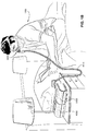
- the nose and mouth form the entrance to the airways of a patient.
- the airways include a series of branching tubes, which become narrower, shorter and more numerous as they penetrate deeper into the lung.
- the prime function of the lung is gas exchange, allowing oxygen to move from the inhaled air into the venous blood and carbon dioxide to move in the opposite direction.
- the trachea divides into right and left main bronchi, which further divide eventually into terminal bronchioles.
- the bronchi make up the conducting airways, and do not take part in gas exchange. Further divisions of the airways lead to the respiratory bronchioles, and eventually to the alveoli.
- the alveolated region of the lung is where the gas exchange takes place, and is referred to as the respiratory zone. See " Respiratory Physiology", by John B. West, Lippincott Williams & Wilkins, 9th edition published 2012 .
- a range of respiratory disorders exist. Certain disorders may be characterised by particular events, e.g. apneas, hypopneas, and hyperpneas.
- respiratory disorders include Obstructive Sleep Apnea (OSA), Cheyne-Stokes Respiration (CSR), respiratory insufficiency, Obesity Hyperventilation Syndrome (OHS), Chronic Obstructive Pulmonary Disease (COPD), Neuromuscular Disease (NMD) and Chest wall disorders.
- OSA Obstructive Sleep Apnea
- CSR Cheyne-Stokes Respiration
- OOS Obesity Hyperventilation Syndrome
- COPD Chronic Obstructive Pulmonary Disease
- NMD Neuromuscular Disease
- Chest wall disorders examples include Obstructive Sleep Apnea (OSA), Cheyne-Stokes Respiration (CSR), respiratory insufficiency, Obesity Hyperventilation Syndrome (OHS), Chronic Obstructive Pulmonary Disease (COPD), Neuromuscular Disease (NMD) and Chest wall disorders.
- Obstructive Sleep Apnea a form of Sleep Disordered Breathing (SDB), is characterised by events including occlusion or obstruction of the upper air passage during sleep. It results from a combination of an abnormally small upper airway and the normal loss of muscle tone in the region of the tongue, soft palate and posterior oropharyngeal wall during sleep.
- the condition causes the affected patient to stop breathing for periods typically of 30 to 120 seconds in duration, sometimes 200 to 300 times per night. It often causes excessive daytime somnolence, and it may cause cardiovascular disease and brain damage.
- the syndrome is a common disorder, particularly in middle aged overweight males, although a person affected may have no awareness of the problem. See US Patent No. 4,944,310 (Sullivan ).
- CSR Cheyne-Stokes Respiration
- CSR cycles rhythmic alternating periods of waxing and waning ventilation known as CSR cycles.
- CSR is characterised by repetitive de-oxygenation and re-oxygenation of the arterial blood. It is possible that CSR is harmful because of the repetitive hypoxia. In some patients CSR is associated with repetitive arousal from sleep, which causes severe sleep disruption, increased sympathetic activity, and increased afterload. See US Patent No. 6,532,959 (Berthon-Jones ).
- Respiratory failure is an umbrella term for respiratory disorders in which the lungs are unable to inspire sufficient oxygen or exhale sufficient CO 2 to meet the patient's needs. Respiratory failure may encompass some or all of the following disorders.
- a patient with respiratory insufficiency (a form of respiratory failure) may experience abnormal shortness of breath on exercise.
- Obesity Hyperventilation Syndrome is defined as the combination of severe obesity and awake chronic hypercapnia, in the absence of other known causes for hypoventilation. Symptoms include dyspnea, morning headache and excessive daytime sleepiness.
- COPD Chronic Obstructive Pulmonary Disease
- COPD encompasses any of a group of lower airway diseases that have certain characteristics in common. These include increased resistance to air movement, extended expiratory phase of respiration, and loss of the normal elasticity of the lung. Examples of COPD are emphysema and chronic bronchitis. COPD is caused by chronic tobacco smoking (primary risk factor), occupational exposures, air pollution and genetic factors. Symptoms include: dyspnea on exertion, chronic cough and sputum production.
- Neuromuscular Disease is a broad term that encompasses many diseases and ailments that impair the functioning of the muscles either directly via intrinsic muscle pathology, or indirectly via nerve pathology.
- Some NMD patients are characterised by progressive muscular impairment leading to loss of ambulation, being wheelchair-bound, swallowing difficulties, respiratory muscle weakness and, eventually, death from respiratory failure.
- Neuromuscular disorders can be divided into rapidly progressive and slowly progressive: (i) Rapidly progressive disorders: Characterised by muscle impairment that worsens over months and results in death within a few years (e.g.
- ALS Amyotrophic lateral sclerosis
- DMD Duchenne muscular dystrophy
- Variable or slowly progressive disorders Characterised by muscle impairment that worsens over years and only mildly reduces life expectancy (e.g. Limb girdle, Facioscapulohumeral and Myotonic muscular dystrophy).
- Symptoms of respiratory failure in NMD include: increasing generalised weakness, dysphagia, dyspnea on exertion and at rest, fatigue, sleepiness, morning headache, and difficulties with concentration and mood changes.
- Chest wall disorders are a group of thoracic deformities that result in inefficient coupling between the respiratory muscles and the thoracic cage.
- the disorders are usually characterised by a restrictive defect and share the potential of long term hypercapnic respiratory failure.
- Scoliosis and/or kyphoscoliosis may cause severe respiratory failure.
- Symptoms of respiratory failure include: dyspnea on exertion, peripheral oedema, orthopnea, repeated chest infections, morning headaches, fatigue, poor sleep quality and loss of appetite.
- a range of therapies have been used to treat or ameliorate such conditions. Furthermore, otherwise healthy individuals may take advantage of such therapies to prevent respiratory disorders from arising. However, these have a number of shortcomings.
- CPAP Continuous Positive Airway Pressure
- NMV Non-invasive ventilation
- IV Invasive ventilation
- Continuous Positive Airway Pressure (CPAP) therapy has been used to treat Obstructive Sleep Apnea (OSA).
- OSA Obstructive Sleep Apnea
- the mechanism of action is that continuous positive airway pressure acts as a pneumatic splint and may prevent upper airway occlusion, such as by pushing the soft palate and tongue forward and away from the posterior oropharyngeal wall.
- Treatment of OSA by CPAP therapy may be voluntary, and hence patients may elect not to comply with therapy if they find devices used to provide such therapy one or more of: uncomfortable, difficult to use, expensive and aesthetically unappealing.
- Non-invasive ventilation provides ventilatory support to a patient through the upper airways to assist the patient breathing and/or maintain adequate oxygen levels in the body by doing some or all of the work of breathing.
- the ventilatory support is provided via a non-invasive patient interface.
- NIV has been used to treat CSR and respiratory failure, in forms such as OHS, COPD, NMD and Chest Wall disorders. In some forms, the comfort and effectiveness of these therapies may be improved.
- IV Invasive ventilation
- These therapies may be provided by a treatment system or device. Such systems and devices may also be used to diagnose a condition without treating it.
- a treatment system may comprise a Respiratory Pressure Therapy Device (RPT device), an air circuit, a humidifier, a patient interface, and data management.
- RPT device Respiratory Pressure Therapy Device
- Another form of treatment system is a mandibular repositioning device.
- a patient interface may be used to interface respiratory equipment to its wearer, for example by providing a flow of air to an entrance to the airways.
- the flow of air may be provided via a mask to the nose and/or mouth, a tube to the mouth or a tracheostomy tube to the trachea of a patient.
- the patient interface may form a seal, e.g., with a region of the patient's face, to facilitate the delivery of gas at a pressure at sufficient variance with ambient pressure to effect therapy, e.g., at a positive pressure of about 10 cmH 2 O relative to ambient pressure.
- the patient interface may not include a seal sufficient to facilitate delivery to the airways of a supply of gas at a positive pressure of about 10 cmH 2 O.
- Certain other mask systems may be functionally unsuitable for the present field.
- purely ornamental masks may be unable to maintain a suitable pressure.
- Mask systems used for underwater swimming or diving may be configured to guard against ingress of water from an external higher pressure, but not to maintain air internally at a higher pressure than ambient.
- Certain masks may be clinically unfavourable for the present technology e.g. if they block airflow via the nose and only allow it via the mouth.
- Certain masks may be uncomfortable or impractical for the present technology if they require a patient to insert a portion of a mask structure in their mouth to create and maintain a seal via their lips.
- Certain masks may be impractical for use while sleeping, e.g. for sleeping while lying on one's side in bed with a head on a pillow.
- the design of a patient interface presents a number of challenges.
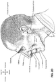
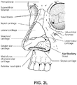
- the face has a complex three-dimensional shape.
- the size and shape of noses and heads varies considerably between individuals. Since the head includes bone, cartilage and soft tissue, different regions of the face respond differently to mechanical forces.
- the jaw or mandible may move relative to other bones of the skull. The whole head may move during the course of a period of respiratory therapy.
- masks suffer from being one or more of obtrusive, aesthetically undesirable, costly, poorly fitting, difficult to use, and uncomfortable especially when worn for long periods of time or when a patient is unfamiliar with a system. Wrongly sized masks can give rise to reduced compliance, reduced comfort and poorer patient outcomes.
- Masks designed solely for aviators, masks designed as part of personal protection equipment (e.g. filter masks), SCUBA masks, or for the administration of anaesthetics may be tolerable for their original application, but nevertheless such masks may be undesirably uncomfortable to be worn for extended periods of time, e.g., several hours. This discomfort may lead to a reduction in patient compliance with therapy. This is even more so if the mask is to be worn during sleep.
- CPAP therapy is highly effective to treat certain respiratory disorders, provided patients comply with therapy. If a mask is uncomfortable, or difficult to use a patient may not comply with therapy. Since it is often recommended that a patient regularly wash their mask, if a mask is difficult to clean (e.g., difficult to assemble or disassemble), patients may not clean their mask and this may impact on patient compliance.
- a mask for other applications may not be suitable for use in treating sleep disordered breathing
- a mask designed for use in treating sleep disordered breathing may be suitable for other applications.
- patient interfaces for delivery of CPAP during sleep form a distinct field.
- Patient interfaces may include a seal-forming structure. Since it is in direct contact with the patient's face, the shape and configuration of the seal-forming structure can have a direct impact the effectiveness and comfort of the patient interface.
- a patient interface may be partly characterised according to the design intent of where the seal-forming structure is to engage with the face in use.
- a seal-forming structure may comprise a first sub-portion to form a seal around the left naris and a second sub-portion to form a seal around the right naris.
- a seal-forming structure may comprise a single element that surrounds both nares in use. Such single element may be designed to for example overlay an upper lip region and a nasal bridge region of a face.
- a seal-forming structure may comprise an element that surrounds a mouth region in use, e.g. by forming a seal on a lower lip region of a face.
- a seal-forming structure may comprise a single element that surrounds both nares and a mouth region in use.
- These different types of patient interfaces may be known by a variety of names by their manufacturer including nasal masks, full-face masks, nasal pillows, nasal puffs and oro-nasal masks.
- a seal-forming structure that may be effective in one region of a patient's face may be inappropriate in another region, e.g. because of the different shape, structure, variability and sensitivity regions of the patient's face.
- a seal on swimming goggles that overlays a patient's forehead may not be appropriate to use on a patient's nose.
- Certain seal-forming structures may be designed for mass manufacture such that one design fit and be comfortable and effective for a wide range of different face shapes and sizes. To the extent to which there is a mismatch between the shape of the patient's face, and the seal-forming structure of the mass-manufactured patient interface, one or both must adapt in order for a seal to form.
- seal-forming structure extends around the periphery of the patient interface, and is intended to seal against the patient's face when force is applied to the patient interface with the seal-forming structure in confronting engagement with the patient's face.
- the seal-forming structure may include an air or fluid filled cushion, or a moulded or formed surface of a resilient seal element made of an elastomer such as a rubber.
- seal-forming structure incorporates a flap seal of thin material positioned about the periphery of the mask so as to provide a self-sealing action against the face of the patient when positive pressure is applied within the mask.
- flap seal of thin material positioned about the periphery of the mask so as to provide a self-sealing action against the face of the patient when positive pressure is applied within the mask.
- additional force may be required to achieve a seal, or the mask may leak.
- shape of the seal-forming structure does not match that of the patient, it may crease or buckle in use, giving rise to leaks.
- seal-forming structure may comprise a friction-fit element, e.g. for insertion into a naris, however some patients find these uncomfortable.
- seal-forming structure may use adhesive to achieve a seal. Some patients may find it inconvenient to constantly apply and remove an adhesive to their face.
- nasal pillow is found in the Adam Circuit manufactured by Puritan Bennett.
- Another nasal pillow, or nasal puff is the subject of US Patent 4,782,832 (Trimble et al .), assigned to Puritan-Bennett Corporation.
- ResMed Limited has manufactured the following products that incorporate nasal pillows: SWIFTTM nasal pillows mask, SWIFTTM II nasal pillows mask, SWIFTTM LT nasal pillows mask, SWIFTTM FX nasal pillows mask and MIRAGE LIBERTYTM full-face mask.
- the following patent applications, assigned to ResMed Limited, describe examples of nasal pillows masks: International Patent Application WO2004/073,778 (describing amongst other things aspects of the ResMed Limited SWIFTTM nasal pillows), US Patent Application 2009/0044808 (describing amongst other things aspects of the ResMed Limited SWIFTTM LT nasal pillows); International Patent Applications WO 2005/063,328 and WO 2006/130,903 (describing amongst other things aspects of the ResMed Limited MIRAGE LIBERTYTM full-face mask); International Patent Application WO 2009/052,560 (describing amongst other things aspects of the ResMed Limited SWIFTTM FX nasal pillows).
- a seal-forming structure of a patient interface used for positive air pressure therapy is subject to the corresponding force of the air pressure to disrupt a seal.
- a variety of techniques have been used to position the seal-forming structure, and to maintain it in sealing relation with the appropriate portion of the face.
- Another technique is the use of one or more straps and/or stabilising harnesses. Many such harnesses suffer from being one or more of ill-fitting, bulky, uncomfortable and awkward to use.
- a respiratory pressure therapy (RPT) device may be used to deliver one or more of a number of therapies described above, such as by generating a flow of air for delivery to an entrance to the airways.
- the flow of air may be pressurised.
- RPT devices include a CPAP device and a ventilator.
- Air pressure generators are known in a range of applications, e.g. industrial-scale ventilation systems. However, air pressure generators for medical applications have particular requirements not fulfilled by more generalised air pressure generators, such as the reliability, size and weight requirements of medical devices. In addition, even devices designed for medical treatment may suffer from shortcomings, pertaining to one or more of: comfort, noise, ease of use, efficacy, size, weight, manufacturability, cost, and reliability.
- RPT Device name A-weighted sound pressure level dB(A) Year (approx.) C-Series TangoTM 31.9 2007 C-Series TangoTM with Humidifier 33.1 2007 S8 EscapeTM II 30.5 2005 S8 EscapeTM II with H4iTM Humidifier 31.1 2005 S9 AutoSetTM 26.5 2010 S9 AutoSetTM with H5i Humidifier 28.6 2010
- RPT device used for treating sleep disordered breathing is the S9 Sleep Therapy System, manufactured by ResMed Limited.
- RPT device is a ventilator.
- Ventilators such as the ResMed StellarTM Series of Adult and Paediatric Ventilators may provide support for invasive and non-invasive non-dependent ventilation for a range of patients for treating a number of conditions such as but not limited to NMD, OHS and COPD.
- the ResMed EloTM 150 ventilator and ResMed VS IIITM ventilator may provide support for invasive and non-invasive dependent ventilation suitable for adult or paediatric patients for treating a number of conditions. These ventilators provide volumetric and barometric ventilation modes with a single or double limb circuit.
- RPT devices typically comprise a pressure generator, such as a motor-driven blower or a compressed gas reservoir, and are configured to supply a flow of air to the airway of a patient. In some cases, the flow of air may be supplied to the airway of the patient at positive pressure.
- the outlet of the RPT device is connected via an air circuit to a patient interface such as those described above.
- the designer of a device may be presented with an infinite number of choices to make. Design criteria often conflict, meaning that certain design choices are far from routine or inevitable. Furthermore, the comfort and efficacy of certain aspects may be highly sensitive to small, subtle changes in one or more parameters.
- a range of artificial humidification devices and systems are known, however they may not fulfil the specialised requirements of a medical humidifier.
- Medical humidifiers are used to increase humidity and/or temperature of the flow of air in relation to ambient air when required, typically where the patient may be asleep or resting (e.g. at a hospital).
- a medical humidifier for bedside placement may be small.
- a medical humidifier may be configured to only humidify and/or heat the flow of air delivered to the patient without humidifying and/or heating the patient's surroundings.
- Room-based systems e.g. a sauna, an air conditioner, or an evaporative cooler
- medical humidifiers may have more stringent safety constraints than industrial humidifiers
- a compliance rule for CPAP therapy is that a patient, in order to be deemed compliant, is required to use the RPT device for at least four hours a night for at least 21 of 30 consecutive days.
- a provider of the RPT device such as a health care provider, may manually obtain data describing the patient's therapy using the RPT device, calculate the usage over a predetermined time period, and compare with the compliance rule. Once the health care provider has determined that the patient has used their RPT device according to the compliance rule, the health care provider may notify a third party that the patient is compliant.
- a mandibular repositioning device (MRD) or mandibular advancement device (MAD) is one of the treatment options for sleep apnea and snoring. It is an adjustable oral appliance available from a dentist or other supplier that holds the lower jaw (mandible) in a forward position during sleep.
- the MRD is a removable device that a patient inserts into their mouth prior to going to sleep and removes following sleep. Thus, the MRD is not designed to be worn all of the time.
- the MRD may be custom made or produced in a standard form and includes a bite impression portion designed to allow fitting to a patient's teeth. This mechanical protrusion of the lower jaw expands the space behind the tongue, puts tension on the pharyngeal walls to reduce collapse of the airway and diminishes palate vibration.
- a mandibular advancement device may comprise an upper splint that is intended to engage with or fit over teeth on the upper jaw or maxilla and a lower splint that is intended to engage with or fit over teeth on the upper jaw or mandible.
- the upper and lower splints are connected together laterally via a pair of connecting rods.
- the pair of connecting rods are fixed symmetrically on the upper splint and on the lower splint.
- the length of the connecting rods is selected such that when the MRD is placed in a patient's mouth the mandible is held in an advanced position.
- the length of the connecting rods may be adjusted to change the level of protrusion of the mandible.
- a dentist may determine a level of protrusion for the mandible that will determine the length of the connecting rods.
- MRDs are structured to push the mandible forward relative to the maxilla while other MADs, such as the ResMed Narval CCTM MRD are designed to retain the mandible in a forward position.
- This device also reduces or minimises dental and temporo-mandibular joint (TMJ) side effects. Thus, it is configured to minimises or prevent any movement of one or more of the teeth.
- TMJ temporo-mandibular joint
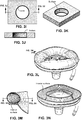
- Some forms of treatment systems may include a vent to allow the washout of exhaled carbon dioxide.
- the vent may allow a flow of gas from an interior space of a patient interface, e.g., the plenum chamber, to an exterior of the patient interface, e.g., to ambient.
- the vent may comprise an orifice and gas may flow through the orifice in use of the mask. Many such vents are noisy. Others may become blocked in use and thus provide insufficient washout. Some vents may be disruptive of the sleep of a bed partner 1100 of the patient 1000, e.g. through noise or focussed airflow.
- ResMed Limited has developed a number of improved mask vent technologies. See International Patent Application Publication No. WO 1998/034,665 ; International Patent Application Publication No. WO 2000/078,381 ; US Patent No. 6,581,594 ; US Patent Application Publication No. US 2009/0050156 ; US Patent Application Publication No. 2009/0044808 .
- Object A-weighted sound pressure dB(A) Notes Vacuum cleaner: Nilfisk Walter Broadly Litter Hog: B+ Grade 68 ISO 3744 at 1m distance Conversational speech 60 1m distance Average home 50 Quiet library 40 Quiet bedroom at night 30 Background in TV studio 20
- PSG Polysomnography
- EEG electroencephalography
- ECG electrocardiography
- EOG electrooculograpy
- EMG electromyography
- PSG for sleep disordered breathing has involved two nights of observation of a patient in a clinic, one night of pure diagnosis and a second night of titration of treatment parameters by a clinician. PSG is therefore expensive and inconvenient. In particular it is unsuitable for home sleep testing.
- Clinical experts may be able to diagnose or monitor patients adequately based on visual observation of PSG signals. However, there are circumstances where a clinical expert may not be available, or a clinical expert may not be affordable. Different clinical experts may disagree on a patient's condition. In addition, a given clinical expert may apply a different standard at different times.
- US 2015/0352306 A1 relates to a patient interface for delivery of a supply of pressurised air or breathable gas to an entrance of a patient's airways comprising: a cushion member that includes a retaining structure and a seal-forming structure permanently connected to the retaining structure; a frame member attachable to the retaining structure; and a positioning and stabilising structure attachable to the frame member.
- WO 2011/022779 A1 relates to a PAP system including a patient interface including sealing arrangement adapted to form a seal with the patient's nose and/ or mouth and headgear to support the sealing arrangement in position on the patient's head.
- the present technology is directed towards providing medical devices used in the diagnosis, amelioration, treatment, or prevention of respiratory disorders having one or more of improved comfort, cost, efficacy, ease of use and manufacturability.
- a first aspect of the present technology relates to apparatus used in the diagnosis, amelioration, treatment or prevention of a respiratory disorder.
- Another aspect of the present technology relates to methods used in the diagnosis, amelioration, treatment or prevention of a respiratory disorder.
- An aspect of certain forms of the present technology is to provide methods and/or apparatus that improve the compliance of patients with respiratory therapy.
- An aspect of the present technology is directed to a seal-forming structure for a patient interface that is configured to form a seal with the patient's nares and the seal-forming structure comprises a support structure forming a continuous loop with an interior surface of the seal-forming structure, the loop structure supporting a superior portion of a patient contacting surface of the seal-forming structure, and the superior portion of the patient contacting surface having a single layer that is not supported by an undercushion.
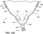
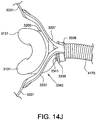
- An aspect of the present technology is directed to a patient interface that comprises: a plenum chamber pressurisable to a therapeutic pressure of at least 6 cmH 2 O above ambient air pressure, said plenum chamber including a plenum chamber inlet port sized and structured to receive a flow of air at the therapeutic pressure for breathing by a patient, a seal-forming structure constructed and arranged to form a seal with a region of the patient's face surrounding an entrance to the patient's airways, the seal-forming structure constructed and arranged to maintain said therapeutic pressure in the plenum chamber throughout the patient's respiratory cycle in use; a positioning and stabilising structure to provide a force to hold the seal-forming structure in a therapeutically effective position on the patient's head, the positioning and stabilising structure comprising a tie, the tie being constructed and arranged so that at least a portion overlies a region of the patient's head superior to an otobasion superior of the patient's head in use; and a vent structure to allow a continuous flow of gases exhaled by the
- the seal-forming structure may comprise an anterior opening formed in a non-patient contacting surface and an anterior tie that spans the anterior opening, and a first end of the support structure may be connected to the anterior tie
- the seal-forming structure may comprise an edge bounding the posterior opening in the patient contacting surface, and a second end of the support structure may be connected to the patient contacting surface at a superior region of the edge
- the seal-forming structure may comprise an undercushion that supports the patient contacting surface
- an inferior portion of the seal-forming structure may include the undercushion and a superior portion of the seal-forming structure may not include the undercushion
- the undercushion may be structured to only support the patient contacting surface against the patient's lip superior.
- An aspect of the present technology is directed to a seal-forming structure for a patient interface, the seal-forming structure constructed and arranged to form a seal with a region of the patient's face surrounding an entrance to the patient's airways, the seal-forming structure constructed and arranged to maintain a therapeutic pressure of at least 6 cmH2O above ambient air pressure in a plenum chamber throughout the patient's respiratory cycle in use.
- the seal-forming structure comprises: a patient-contacting surface configured to engage the patient's facial skin to form a seal; a posterior opening formed in the patient-contacting surface, the posterior opening configured to provide the flow of air at said therapeutic pressure to the patient's nares; and a support structure extending from the patient contacting surface to an interior surface of the seal-forming structure, the support structure and the interior surface forming a continuous loop, wherein the patient interface is configured to allow the patient to breath from ambient through their mouth in the absence of a flow of pressurised air through the plenum chamber inlet port, or the patient interface is configured to leave the patient's mouth uncovered.
- the seal-forming structure may comprise an anterior opening formed in a non-patient contacting surface and an anterior tie that spans the anterior opening, and a first end of the support structure may be connected to the anterior tie
- the seal-forming structure may comprise an edge bounding the posterior opening in the patient contacting surface, and a second end of the support structure may be connected to the patient contacting surface at a superior region of the edge
- the seal-forming structure may comprise an undercushion that supports the patient contacting surface
- an inferior portion of the seal-forming structure may include the undercushion and a superior portion of the seal-forming structure may not include the undercushion
- the undercushion may be structured to only support the patient contacting surface against the patient's lip superior.
- Another aspect of the present technology is directed to a patient interface for sealed delivery of a flow of air at a continuously positive pressure with respect to ambient air pressure to an entrance to the patient's airways including at least an entrance of a patient's nares, wherein the patient interface is configured to maintain a therapy pressure in a range of about 4 cmH2O to about 30 cmH2O above ambient air pressure in use, throughout the patient's respiratory cycle, while the patient is sleeping, to ameliorate sleep disordered breathing.
- the patient interface may comprise: a seal forming structure to form a seal with the entrance to the patient's airways including at least the entrance of the patient's nares; a plenum chamber pressurised at a pressure above ambient pressure in use, the seal forming structure attached to the plenum chamber; and a positioning and stabilising structure to maintain the seal forming structure in sealing contact with an area surrounding the entrance to the patient's airways while maintaining a therapeutic pressure at the entrance to the patient's airways, wherein the positioning and stabilising structure is connected to the plenum chamber such that forces imposed on the positioning and stabilising structure by movement of the patient's head are decoupled from the plenum chamber and the seal forming structure.
- the positioning and stabilising structure may comprise a rigidiser arm assembly, the rigidiser arm assembly being flexibly attached to the plenum chamber, (b) the rigidiser arm assembly may be flexibly attached to the plenum chamber such that in use the rigidiser arm assembly is movable substantially independently relative to the plenum chamber and the seal forming structure, (c) the rigidiser arm assembly may be flexibly attached to the plenum chamber such that movement of the positioning and stabilising structure in use does not disrupt the sealing contact of the seal forming structure with the area surrounding the entrance to the patient's airways, (d) the rigidiser arm assembly may be flexibly attached to a medial, anterior surface of the plenum chamber, (e) the rigidiser arm assembly may be flexibly attached to the plenum chamber with an elastic material, (f) the positioning and stabilising structure may comprise a plurality of straps to secure the patient interface on the patient's head in use by attachment to the rigidiser arm assembly, (g) the plurality of straps may be only connected to the rigid
- Another aspect of the present technology may be directed to a patient interface for sealed delivery of a flow of air at a continuously positive pressure with respect to ambient air pressure to an entrance to the patient's airways including at least an entrance of a patient's nares, wherein the patient interface is configured to maintain a therapy pressure in a range of about 4 cmH2O to about 30 cmH2O above ambient air pressure in use, throughout the patient's respiratory cycle, while the patient is sleeping, to ameliorate sleep disordered breathing.
- the patient interface may comprise: a seal forming structure to form a seal with the entrance to the patient's airways including at least the entrance of the patient's nares; a plenum chamber pressurised at a pressure above ambient pressure in use, the seal forming structure attached to the plenum chamber; and a positioning and stabilising structure to maintain the seal forming structure in sealing contact with an area surrounding the entrance to the patient's airways while maintaining a therapeutic pressure at the entrance to the patient's airways, wherein the positioning and stabilising structure comprises a rigidiser arm assembly that is flexibly connected to the plenum chamber by at least one flexible decoupling structure such that forces imposed on the positioning and stabilising structure by movement of the patient's head are decoupled from the plenum chamber and the seal forming structure.
- the plenum chamber may comprise a plenum chamber connector and the rigidiser arm assembly may comprise a rigidiser arm connection ring, and the plenum chamber connector and the rigidiser arm connection ring may be flexibly connected by the at least one flexible decoupling structure, wherein the plenum chamber connector is fixed to a medial, anterior surface of the plenum chamber,
- the rigidiser arm assembly may comprise two rigider arms, each of the rigidiser arms configured to pass along one of the patient's cheeks in use, and the rigidiser arm assembly may comprise two rigidiser arm connectors, each of the rigidiser arm connectors connecting a corresponding rigidiser arm to the rigidiser arm connection ring,
- the rigidiser arm connection ring and the two rigidiser arm connectors may be formed from one homogeneous piece of a first material,
- each of the rigidiser arms may be formed from a second material that is different from the first material,
- the first material may be more rigid than the second material
- each of the rigidiser arms may be
- Another aspect of the present technology is directed to a seal-forming structure for a patient interface configured to provide sealed delivery of a flow of air at a continuously positive pressure with respect to ambient air pressure to an entrance to the patient's airways including at least an entrance of a patient's nares, wherein the patient interface is configured to maintain a therapy pressure in a range of about 4 cmH2O to about 30 cmH2O above ambient air pressure in use, throughout the patient's respiratory cycle, while the patient is sleeping, to ameliorate sleep disordered breathing.
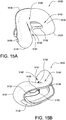
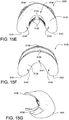
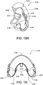
- the seal-forming structure may comprise: an outer membrane configured to form a seal with the inferior periphery of the patient's nose, the outer membrane having an inferior portion to form a seal with the patient's lip superior, and the outer membrane having two alar sealing portions, each alar sealing portion being shaped and dimensioned to seal between corresponding ones of the patient's nasal ala and nasolabial sulcus; at least one opening formed through the outer membrane to provide sealed delivery of the flow of air at the continuously positive pressure with respect to ambient air pressure to one or both of the patient's nares; an undercushion to support the inferior portion against the patient's lip superior and having alar sealing portion supports that correspond to each of the alar sealing portions to support the alar sealing portions between corresponding ones of the patient's nasal ala and nasolabial sulcus.
- the undercushion layer may extend partially around the periphery of the outer membrane, (b) the undercushion layer may terminate at each lateral side at the alar sealing portion supports, (c) the seal-forming structure may comprise a superior portion to form a seal proximal to the tip of the patient's nose, the superior portion not being supported by the undercushion layer, (d) in use the seal-forming structure may not extend beyond the patient's septal cartilage, (e) in use the seal-forming structure may not extend beyond the patient's alar cartilage, (f) the seal-forming structure may comprise a lateral portion on each lateral side of the seal-forming structure to form a seal with a corresponding ala of the patient's nose, (g) the outer membrane may comprise a thickened region at each lateral portion that is thicker than the remainder of the outer membrane, (h) the seal-forming structure may comprise one opening formed through the outer membrane to provide sealed delivery of the flow of air at the continuously positive pressure with respect to ambient air pressure
- Another aspect of the present technology is directed to a patient interface for sealed delivery of a flow of air at a continuously positive pressure with respect to ambient air pressure to an entrance to the patient's airways including at least an entrance of a patient's nares, wherein the patient interface is configured to maintain a therapy pressure in a range of about 4 cmH2O to about 30 cmH2O above ambient air pressure in use, throughout the patient's respiratory cycle, while the patient is sleeping, to ameliorate sleep disordered breathing.
- the patient interface may comprise: a plenum chamber pressurised at a pressure above ambient pressure in use; the seal forming structure including one or more of the features described in the two preceding paragraphs, the seal forming structure having a plenum chamber connection portion attached to the plenum chamber; and a positioning and stabilising structure to maintain the seal forming structure in sealing contact with an area surrounding the entrance to the patient's airways while maintaining a therapeutic pressure at the entrance to the patient's airways.
- Another aspect of one form of the present technology is a patient interface that is moulded or otherwise constructed with a perimeter shape which is complementary to that of an intended wearer.
- An aspect of one form of the present technology is a method of manufacturing apparatus.
- An aspect of certain forms of the present technology is a medical device that is easy to use, e.g. by a person who does not have medical training, by a person who has limited dexterity, vision or by a person with limited experience in using this type of medical device.
- An aspect of one form of the present technology is a patient interface that may be washed in a home of a patient, e.g., in soapy water, without requiring specialised cleaning equipment.
- An aspect of one form of the present technology is a humidifier tank that may be washed in a home of a patient, e.g., in soapy water, without requiring specialised cleaning equipment.
- portions of the aspects may form sub-aspects of the present technology.
- various ones of the sub-aspects and/or aspects may be combined in various manners and also constitute additional aspects or sub-aspects of the present technology.
- the present technology comprises a method for treating a respiratory disorder comprising the step of applying positive pressure to the entrance of the airways of a patient 1000.
- a supply of air at positive pressure is provided to the nasal passages of the patient via one or both nares.
- mouth breathing is limited, restricted or prevented.
- the present technology comprises an apparatus or device for treating a respiratory disorder.
- the apparatus or device may comprise an RPT device 4000 for supplying pressurised air to the patient 1000 via an air circuit 4170 to a patient interface 3000.
- a non-invasive patient interface 3000 in accordance with one aspect of the present technology comprises the following functional aspects: a seal-forming structure 3100, a plenum chamber 3200, a positioning and stabilising structure 3300, a vent 3400, one form of connection port 3600 for connection to air circuit 4170, and a forehead support 3700.
- a functional aspect may be provided by one or more physical components.
- one physical component may provide one or more functional aspects.
- the seal-forming structure 3100 is arranged to surround an entrance to the airways of the patient so as to facilitate the supply of air at positive pressure to the airways.
- a patient interface is unable to comfortably deliver a minimum level of positive pressure to the airways, the patient interface may be unsuitable for respiratory pressure therapy.
- the patient interface 3000 in accordance with one form of the present technology is constructed and arranged to be able to provide a supply of air at a positive pressure of at least 6 cmH 2 O with respect to ambient.
- the patient interface 3000 in accordance with one form of the present technology is constructed and arranged to be able to provide a supply of air at a positive pressure of at least 10 cmH 2 O with respect to ambient.
- the patient interface 3000 in accordance with one form of the present technology is constructed and arranged to be able to provide a supply of air at a positive pressure of at least 20 cmH 2 O with respect to ambient.
- a seal-forming structure 3100 provides a target seal-forming region, and may additionally provide a cushioning function.
- the target seal-forming region is a region on the seal-forming structure 3100 where sealing may occur.
- the region where sealing actually occurs- the actual sealing surface- may change within a given treatment session, from day to day, and from patient to patient, depending on a range of factors including for example, where the patient interface was placed on the face, tension in the positioning and stabilising structure and the shape of a patient's face.
- the target seal-forming region is located on an outside surface of the seal-forming structure 3100.
- the seal-forming structure 3100 is constructed from a biocompatible material, e.g. silicone rubber.
- a seal-forming structure 3100 in accordance with the present technology may be constructed from a soft, flexible, resilient material such as silicone.
- a system comprising more than one a seal-forming structure 3100, each being configured to correspond to a different size and/or shape range.
- the system may comprise one form of a seal-forming structure 3100 suitable for a large sized head, but not a small sized head and another suitable for a small sized head, but not a large sized head.
- the seal-forming structure includes a sealing flange utilizing a pressure assisted sealing mechanism.
- the sealing flange can readily respond to a system positive pressure in the interior of the plenum chamber 3200 acting on its underside to urge it into tight sealing engagement with the face.
- the pressure assisted mechanism may act in conjunction with elastic tension in the positioning and stabilising structure.
- the seal-forming structure 3100 comprises a sealing flange and a support flange.
- the sealing flange comprises a relatively thin member with a thickness of less than about 1mm, for example about 0.25mm to about 0.45mm, which extends around the perimeter of the plenum chamber 3200.
- Support flange may be relatively thicker than the sealing flange.
- the support flange is disposed between the sealing flange and the marginal edge of the plenum chamber 3200, and extends at least part of the way around the perimeter.
- the support flange is or includes a springlike element and functions to support the sealing flange from buckling in use.
- the seal-forming structure may comprise a compression sealing portion or a gasket sealing portion.
- the compression sealing portion, or the gasket sealing portion is constructed and arranged to be in compression, e.g. as a result of elastic tension in the positioning and stabilising structure.
- the seal-forming structure comprises a tension portion.
- the tension portion is held in tension, e.g. by adjacent regions of the sealing flange.
- the seal-forming structure comprises a region having a tacky or adhesive surface.
- a seal-forming structure may comprise one or more of a pressure-assisted sealing flange, a compression sealing portion, a gasket sealing portion, a tension portion, and a portion having a tacky or adhesive surface.
- the non-invasive patient interface 3000 comprises a seal-forming structure that forms a seal in use on a nose bridge region or on a nose-ridge region of the patient's face.
- the seal-forming structure includes a saddle-shaped region constructed to form a seal in use on a nose bridge region or on a nose-ridge region of the patient's face.
- the non-invasive patient interface 3000 comprises a seal-forming structure that forms a seal in use on an upper lip region (that is, the lip superior) of the patient's face.
- the seal-forming structure includes a saddle-shaped region constructed to form a seal in use on an upper lip region of the patient's face.
- the non-invasive patient interface 3000 comprises a seal-forming structure that forms a seal in use on a chin-region of the patient's face.
- the seal-forming structure includes a saddle-shaped region constructed to form a seal in use on a chin-region of the patient's face.
- the seal-forming structure that forms a seal in use on a forehead region of the patient's face may cover the eyes in use.
- the seal-forming structure of the non-invasive patient interface 3000 comprises a pair of nasal puffs, or nasal pillows, each nasal puff or nasal pillow being constructed and arranged to form a seal with a respective naris of the nose of a patient.
- Nasal pillows in accordance with an aspect of the present technology include: a frusto-cone, at least a portion of which forms a seal on an underside of the patient's nose, a stalk, a flexible region on the underside of the frusto-cone and connecting the frusto-cone to the stalk.
- the structure to which the nasal pillow of the present technology is connected includes a flexible region adjacent the base of the stalk.
- the flexible regions can act in concert to facilitate a universal joint structure that is accommodating of relative movement both displacement and angular of the frusto-cone and the structure to which the nasal pillow is connected.
- the frusto-cone may be axially displaced towards the structure to which the stalk is connected.
- FIGS. 7A to 7M depict a seal-forming structure 3100 according to an example of the present technology.
- Figs. 12A to 12E depict a patient interface 3000 with the seal-forming structure 3100 of this example of the present technology worn by a patient.
- the seal-forming structure 3100 may be characterized as a nasal cradle cushion.
- the seal-forming structure 3100 may be structured to seal with the patient's face around the patient's nares to provide the pressurized, breathable air to the patient's nasal airways while not covering the patient's mouth.
- An inferior portion of the seal-forming structure 3100 may engage the patient's lip superior to form a seal, and the seal-forming structure 3100 may not extend beyond the lip superior, i.e., to the patient's upper vermilion.
- a superior portion of the seal-forming structure 3100 may be structured to engage the patient's nose inferior to the patient's nasal bone to form a seal.
- a superior portion of the seal-forming structure 3100 may be structured to engage the patient's nose inferior to the patient's pronasale to form a seal.
- Lateral portions of the seal-forming structure 3100 may be structured to engage the patient's nasal alar and the patient's face between the patient's nasal alar and the patient's cheeks to form a seal, as can be seen in Figs. 12D and 12E .
- the lateral portions of the seal-forming structure 3100 may be structured to extend beyond the alar crest point to engage the patient's face and form a seal.
- the seal-forming structure 3100 may include attributes of nasal cradle cushions disclosed in International Application Publication Nos. WO 2014/110626, filed January 16, 2014 , and WO 2015/070289, filed November 14, 2014 , each of which is incorporated herein by reference in its entirety.
- the seal-forming structure 3100 includes a connection region 3102 at an anterior side thereof.
- the connection region 3102 is structured to connect the seal-forming structure 3100 to the plenum chamber 3200.
- the connection region 3102 provides an interface for engagement with the plenum chamber 3200.
- the connection at the connection region 3102 may be substantially airtight to allow the desired pressure level to be maintained in the plenum chamber 3200 during use.
- the connection region 3102 may connect with the plenum chamber 3200 via a mechanical connection such as a friction fit, a snap fit, or a mechanical interlock of corresponding overhanging portions.
- the connection region 3102 may provide a removable connection to the plenum chamber 3200.
- the removable connection allows the seal-forming structure 3100 to be removed for cleaning or replacement.
- the connection between the seal-forming structure 3100 and the plenum chamber 3200 may be permanent, e.g., via an adhesive or overmoulding, such that separating the seal-forming structure 3100 and the plenum chamber 3200 would damage one or both components.
- the seal-forming structure 3100 and the plenum chamber 3200 may be replaceable as a combined unit.
- the seal-forming structure 3100 and the plenum chamber 3200 may be formed from one homogeneous piece of material, which may be elastomeric or which may be silicone.
- the connection region 3102 of this example surrounds an anterior opening 3104 or hole.
- the anterior opening 3104 may be in fluid communication with the plenum chamber 3200 to receive the flow of pressurized, breathable gas, and exhaled gas from the patient may pass through the anterior opening 3104 to the plenum chamber 3200 to be exhausted by the vent 3400.
- the anterior opening 3104 in this example is also divided by an anterior tie 3108 that spans the anterior opening 3104 in a superior-inferior direction between an inferior portion of the connection region 3102 and a superior portion of the connection region 3102.
- the anterior tie 3108 may span the minor axis of the anterior opening 3104.
- the seal-forming structure 3100 of this example also includes a non-patient contacting surface 3116 surrounding the connection region 3102.
- the non-patient contacting surface 3116 faces away from the patient's face and does not contact the patient's face in use.
- the non-patient contacting surface 3116 may also at least partly contact the plenum chamber 3200.
- the seal-forming structure 3100 of this example also includes a patient-contacting surface 3114.
- the patient-contacting surface 3114 faces the patient's face in use.
- the patient-contacting surface 3114 may at least partially seal against the patient's facial skin in use.
- the patient-contacting surface 3114 is arranged such that the patient's facial skin contacts the patient-contacting surface 3114 in use.
- the patient's facial skin may contact only parts of the patient-contacting surface 3114 or the patient's facial skin may contact all of the patient-contacting surface 3114 in use.
- the patient-contacting surface 3114 may be adjacent to the non-patient contacting surface 3116.
- the patient-contacting surface 3114 may also be contiguous with the non-patient contacting surface 3116.
- the patient-contacting surface 3114 and the non-patient contacting surface 3116 may be at least one of frosted, opaque, smooth, and glossy.
- the patient-contacting surface 3114 and the non-patient contacting surface 3116 may have different surface textures, e.g., frosted, opaque, smooth, and/or glossy.
- the seal-forming structure 3100 of this example also includes a chamber 3120 bounded at least partially by an interior surface 3112 of the seal-forming structure 3100.
- the chamber 3120 may be pressurized up to 30 cmH 2 O by the pressurized, breathable gas received from the plenum chamber 3200 during use.
- a posterior opening 3106 or hole is formed in the patient-contacting surface 3114.
- Pressurized, breathable gas in the chamber 3120 of the seal-forming structure 3100 is communicated to the patient's nares through the posterior opening 3106.
- Gas exhaled from the patient's nares is communicated through the posterior opening 3106 to the chamber 3120 to be exhausted via the vent 3400.
- the posterior opening 3106 may be a single opening formed in the patient-contacting surface 3114 or the posterior opening 3106 may be divided into two separate openings that each communicates with a corresponding naris of the patient.
- the posterior opening 3106 may be bounded by an edge 3118 of the patient-contacting surface 3114.
- the seal-forming structure 3100 of this example also includes a support structure 3110 that can be seen in FIGS. 7C , 7J , and 7M .
- the support structure 3110 is connected to the anterior tie 3108 at one end, and the connection is with the surface of the anterior tie 3108 that faces the interior of the chamber 3120 or the connection faces in a posterior direction relative to the seal-forming structure 3100.
- the other end of the support structure 3110 is connected to the patient-contacting surface 3114 at the edge 3118.
- the patient-contacting surface 3114 of the seal-forming structure 3100 may be a single layer that engages the patient's nose proximate to the pronasale.
- the single layer of the seal-forming structure 3100 in this region may be more flexible as compared to a dual-wall arrangement, i.e., an arrangement with an undercushion, which may provide a more comfortable and effective seal for a wider range of nose shapes.
- Such a single layer arrangement may be more prone to blowout, e.g., where the pressurized, breathable gas causes the patient-contacting surface 3114 of the seal-forming structure 3100 to disengage from the patient's nose.
- the support structure 3110 counteracts this effect by tying the edge 3118 of the patient-contacting surface 3114 to another portion of the seal-forming structure 3100.
- the support structure 3110 may provide support to the superior portion of the patient-contacting surface 3114 of the seal-forming structure 3100 to prevent blowout by restraining deflection of the edge 3118 and the surrounding patient-contacting surface 3114.
- Blowout may be understood to refer to the deformation of the seal forming structure 3100 that is caused, at least in part, by the pressure differential resulting from the application of pressure during therapy such that the patient-contacting surface 3114 is displaced from sealing contact with the patient's face, e.g., around the underside of the patient's nose.
- the patient may pull the patient interface 3000 away from the face during therapy ( i.e., while pressure is being applied) and when the patient interface 3000 is displaced from the patient's face by the patient, the force of the therapy pressure may cause the seal forming structure 3100 to deform.
- the patient-contacting surface 3114 of the seal forming structure 3100 may be displaced due to deformation such that an ineffective seal is formed and pressurized gas leaks from the seal forming structure 3100.
- the internal pressurisation of the plenum chamber 3200 it is possible for the internal pressurisation of the plenum chamber 3200 to be disturbed and cause a pressure gradient proximal to the edge 3118.
- the pressure gradient may provide a force, which may ultimately lead to blow out of the patient-contacting surface 3114.
- Displacement of the patient-contacting surface 3114 during blow out may move the edge 3118 into a position that interrupts the seal by forming leak paths when the seal-forming structure 3100 is again repositioned onto the face.
- blowout of the seal forming structure 3100 occurs at regions proximal to the patient's eyes (e.g., when the patient-contacting surface 3114 proximal to the nasal alar is displaced)
- the pressurized gas may flow towards the patient's eyes, which may be particularly disruptive and bothersome to the patient. Accordingly, it is advantageous to reduce blowout so that adequate sealing is maintained to ensure that the patient receives gas at the intended pressure and so that the patient is not disturbed.
- blow out may subject the seal forming structure 3100 to may be in an outward direction, e.g., away from the patient's face. Indeed, in extreme conditions under high internal pressurisation, blow out may include the seal forming structure 3100 folding backwards upon itself. For example, without the support structure 3110, the patient-contacting surface 3114 might deflect such that the edge 3118 contacts the patient-contacting surface 3114.
- the nose shape can be highly variable in profile between users. Moreover, to seal in this region the inner edge of the patient-contacting surface 3114 may bend inwards (e.g., into the plenum chamber and orthogonal to the Frankfort horizontal) and deform to follow the profile of the sides of the nose. As such, this area may be particularly prone to seal interruptions following blow out. That is, if the patient-contacting surface 3114 is outwardly displaced (e.g., away from the patient's face) during blow out, it is often difficult to return the edge 3118 to a sealing position due to resistance from the force of the pressurized gas.
- Blowout may also occur in other areas such as the cheek region or at the upper or lower lip regions which are less prone to seal interruption, but these regions have a generally flatter profile substantially along the coronal plane.
- the edge 3118 may not move significantly from a position that is required to seal along this plane and often the sealing force provided by the positioning and stabilising structure 3300 is sufficient to reposition the edge 3118 to an orientation required to regain seal.
- dual wall seal forming structures 3100 may be susceptible to blowout
- single wall seal forming structures 3100 such as those disclosed in examples of the present technology, may be particularly susceptible to blowout.
- the absence of an additional undercushion structure supporting the patient-contacting surface 3114 may be understood to allow the patient-contacting surface 3114 to deform and deflect more easily.
- the undercushion in a dual wall cushion may help to reposition the outer, sealing wall against the patient's face when the patient interface 3000 is repositioned, but this assistance may be absent in a single wall cushion.
- the support structure 3110 may also partially contact the patient's columella to prevent the patient's nose from protruding into the chamber 3120 of the seal-forming structure 3100.
- the support structure 3110 may also support the patient-contacting surface 3114 and urge the patient-contacting surface 3114 into engagement with the patient's nose proximate to the pronasale to ensure effective sealing.
- FIG. 7J for example, also shows that the support structure 3110 does not span the posterior opening 3106 and does not extend between a superior portion and an inferior portion of the edge 3118.
- the support structure 3110 may, along with the interior surface 3112 and the anterior tie 3108 of the seal-forming structure 3100, form a continuous loop, as can be seen in FIG. 7G .
- the support structure 3110 may be connected to the interior surface 3112 of the seal-forming structure 3100 and not to the anterior tie 3108.
- the anterior tie 3108 may be omitted.
- FIG. 7G also shows that the support structure 3110 is curved slightly inward into the chamber 3120 in an undeformed state. This curvature may allow the support structure 3110 to better accommodate the patient's nose, including the pronasale. Alternatively, the support structure 3110 may be straight in an undeformed state of another example. Additionally, FIG. 7G shows that the patient-contacting surface 3114 is contiguous with an external or posterior surface of the support structure 3110. In an alternative example, the support structure 3110 may be connected to the interior surface 3112 of the seal-forming structure 3100 opposite the patient-contacting surface 3114 such that the edge 3118 separates the patient-contacting surface 3114 and the support structure 3110.
- the seal-forming structure 3100 may include attributes of the tie 3110 disclosed by International Application Publication No. WO 2016/149769, filed March 24, 2016 , which is incorporated herein by reference in its entirety.
- the seal-forming structure 3100 may also include an undercushion 3122 that supports a portion of the patient-contacting surface 3114, as can be seen in FIGS. 7G to 7M .
- the undercushion 3122 may only support an inferior portion of the undercushion 3122.
- the undercushion 3122 may be provided to only the lower half of the seal-forming structure 3100.
- the undercushion 3122 of these examples may be configured to support the patient-contacting surface 3114 against the patient's lip superior to ensure an effective seal.
- a similar undercushion layer 3135 is disclosed by the examples depicted in Figs. 15A to 15K .
- the seal-forming structure 3130 may include an outer membrane 3139 to seal against the patient's face and around the entrance(s) to the patient's airways, such as the nares, as shown in Figs. 15A to 15C , 15E, and 15F .
- the outer membrane 3139 may form a seal around the inferior periphery of the patient's nose.
- the seal-forming structures 3130 depicted in FIGS. 13A-13I , 14A-14J , and 15A-15K each have a pair of openings 3132, each of which provides the flow of pressurized gas to a corresponding naris of the patient's nose.
- These examples also include a columella engagement portion 3133 between the openings 3132 that engages the patient's columella.
- the columella engagement portion 3133 may prevent the patient's nose from extending through the openings 3132 and into the interior region of the seal-forming structure 3130.
- the outer membrane 3139 may also include several regions that seal against different respective regions of the patient's face. Such examples are depicted in FIGS. 15A-15K .
- the outer membrane 3139 of the exemplary seal-forming structure 3130 may include a superior portion 3140 that forms a seal at the pronasale region, i.e., the tip, of the patient's nose, as shown in Figs. 13A to 13C , 14A , 14B , and 14E .
- the outer membrane 3139 may be shaped and dimensioned such that in use the superior portion 3140 does not extend beyond the patient's septal cartilage or the patient's alar cartilage, which are depicted in FIGS. 2H, 2I , and 2L .
- the superior portion 3140 may not engage the patient's nose in use beyond the pronasale.
- the seal-forming structure 3130 may also include an inferior portion 3141 that forms a seal with the patient's lip superior, i.e., the upper lip.
- the inferior portion 3141 may be curved to correspond to the curvature of the patient's lip superior.
- the seal-forming structure 3130 may also include lateral portions 3142 to seal around and under the alae of the patient's nose.
- the seal-forming structure 3130 may also include alar sealing portions 3131 between the inferior portion 3141 and each lateral portion 3142 that form a seal against the patient's face between the ala and corresponding nasolabial sulcus on each side of the patient's nose, as shown in Figs. 13A to 13C .
- the outer membrane 3139 of the seal-forming structure 3130 may also include thickened regions 3134 at each lateral portion 3142.
- FIGS. 14H and 14I depict the outline of the thickened regions 3134, but it should be understood that the additional thickness of the outer membrane 3139 at the thickened regions 3134 may extend inwardly from an interior surface of outer membrane 3139 such that the patient-contacting surface of the outer membrane 3139 is smooth.
- FIGS. 15D and 15I depict such examples.
- the thickened regions 3134 may prevent buckling of the outer membrane 3139 of the seal-forming structure 3130 in use by providing additional structural strength, while allowing the remaining regions of the outer membrane 3139 to be relatively thin and, thus, more conformable to the contours of the patient's face.
- the seal-forming structure 3130 may also include an undercushion layer 3135 to support the outer membrane 3139 against the patient's face in use to ensure adequate pneumatic sealing.
- the undercushion layer 3135 may extend only around the inferior half of the outer membrane 3139. Accordingly, the undercushion layer 3135 may provide support for only the inferior portion 3141 of the outer membrane 3139 against the patient's lip superior.
- the undercushion layer 3135 may also include alar sealing portion supports 3137 that extend into and support the respective alar sealing portions 3131 of the outer membrane 3139. The alar sealing portion supports 3137 may prevent creases in the outer membrane 3139.
- the alar sealing portion supports 3137 may also help support the alar sealing portions 3131 when engaged with the patient's face between the alae and the nasolabial sulci - the complex geometry of this region of the face may require additional support to ensure that an adequate seal is maintained.
- the outer membrane 3139 of the seal forming structure 3130 and the undercushion layer 3135 may be formed from one homogeneous piece of material, which may be silicone according to example of the present technology.
- the undercushion layer 3135 may prevent buckling of the outer membrane 3139, which may be thinner and therefore more susceptible to buckling when urged against the patient's face.
- the undercushion layer 3135 may provide support for the seal-forming structure 3130 by resisting the tension forces generated by the positioning and stabilising structure 3330.
- the undercushion layer 3135 may provide vertical support of the seal-forming structure 3130 by preventing the seal-forming structure 3130 from moving in a superior direction relative to the patient's nose due to forces from the positioning and stabilizing structure 3130 that are directed at least partially in a superior direction relative to the patient's nose.
- the undercushion layer 3135 may provide support for the seal-forming structure 3130 in lateral directions by resisting forces of the positioning and stabilising structure 3330 that push the seal-forming structure 3130 onto the patient's face in use.
- Such enhancements to lateral stability of the seal-forming structure 3130 may be particularly enhanced when the flow of air from the RPT device 4000 is turned off during fitting of the patient interface 3000.
- the undercushion layer 3135 may provide stability by resisting movement of the seal-forming structure 3130 when engaged with the patient's face in use and/or may aid in locating the seal-forming structure 3130 by aligning it with the patient's nose in use.
- the undercushion layer 3135 may aid in locating the seal-forming structure 3130 in lateral directions by encouraging the seal-forming structure 3130 to engage the patient's face at an optimally centered position relative to the patient's nose and may also resist lateral movement of the seal-forming structure 3130 when subjected to external forces by the patient or surroundings (e.g., a pillow or tube drag).
- the undercushion layer 3135 may also aid in locating the seal-forming structure 3130 in a superior direction relative to the patient's nose by encouraging the seal-forming structure 3130 to engage the patient's face at an optimally centered position relative to the patient's nose and may also resist movement in a superior direction when subjected to external forces by the patient or surroundings (e.g., a pillow or tube drag).
- the outer membrane 3139 of the seal-forming structure 3130 may be shaped and dimensioned at the corner regions of the outer membrane, i.e., the regions between the superior portion 3140 and the lateral portions 3142 to accommodate patients with certain anthropometry that have a large portion of their nasal vestibule (nostril opening) exposed at the side/laterally. Typically such patients have a high alar rim or a hanging columella and as such it may be beneficial to extend the superior portion 3140 and the lateral portions 3142 to accommodate such patients. Structuring the superior portion 3140 and the lateral portions 3142 in this way may also prevent crushing of the outer membrane 3139 or unintended deformation of the outer membrane 3139 when pressurized gas is not being supplied ( e.g. , when the user has just donned the mask) to improve usability when donning, or when there is low pressure therapy (less than 4cm H2O).
- the seal-form structure 3130 may also include a recess or recessed portion 3136 at its anterior side.
- the recess 3136 provides space for the rigidiser arm connectors 3337 that are described in detail below to move when forces are imparted on the rigidiser arms 3331 by the patient in use.
- the exemplary positioning and stabilising structure 3330 may include a rigidiser arm assembly that may move laterally. Accordingly, the recess 3136 may provide a clearance in the seal-forming structure 3130 for the rigidiser arm connectors 3337. Also, the recess 3136 may maximise the cushioning properties of the undercushion layer 3135 around the patient's top lip.
- the seal-forming structure 3130 may also include a plenum chamber connection portion 3138 at which the seal-forming structure 3130 attaches to the plenum chamber 3200.
- This connection may be permanent, e.g., due to a mechanical interlock or chemical bond, or the connection may be releasable to allow the patient to separate the seal-forming structure 3130 from the plenum chamber 3200.
- the connection at the plenum chamber connection portion 3138 may be substantially airtight to allow the desired pressure level to be maintained in the plenum chamber 3200 during use.
- the plenum chamber connection portion 3138 may surround the entire anterior periphery of the seal-forming structure 3130 for attachment to the plenum chamber 3200.
- FIG. 15K also shows how the undercushion layer 3135 may be profiled to conform to the patient's upper lip, while minimizing leak through the seal formed by the outer membrane 3139.
- the undercushion layer 3135 includes outwardly curved portions 3145 that are curved to generally follow the contours of the patient's upper lip, since the undercushion layer 3135 will support the outer membrane 3139 against the patient's upper lip.
- Inwardly curved portions 3144 are also shown between the outwardly curved portions 3145 on the undercushion layer 3135.
- inwardly curved portions 3144 help the undercushion layer 3135 support the outer membrane 3139 against the patient's upper lip to prevent leak by being curved inwardly such that a given displacement of the undercushion layer 3135 at the inwardly curved portions 3144 does not displace the undercushion layer 3135 so far that air leaks past the outer membrane 3139.
- the inwardly curved portions 3144 are located to prevent leak in leak-prone areas, which are typically along the lip superior and below the nostrils and ala.
- the plenum chamber 3200 has a perimeter that is shaped to be complementary to the surface contour of the face of an average person in the region where a seal will form in use. In use, a marginal edge of the plenum chamber 3200 is positioned in close proximity to an adjacent surface of the face. Actual contact with the face is provided by the seal-forming structure 3100.
- the seal-forming structure 3100 may extend in use about the entire perimeter of the plenum chamber 3200. In some forms, the plenum chamber 3200 and the seal-forming structure 3100 are formed from a single homogeneous piece of material.
- the plenum chamber 3200 does not cover the eyes of the patient in use. In other words, the eyes are outside the pressurised volume defined by the plenum chamber. Such forms tend to be less obtrusive and / or more comfortable for the wearer, which can improve compliance with therapy.
- the plenum chamber 3200 is constructed from a transparent material, e.g. a transparent polycarbonate.
- a transparent material can reduce the obtrusiveness of the patient interface, and help improve compliance with therapy.
- the use of a transparent material can aid a clinician to observe how the patient interface is located and functioning.
- the plenum chamber 3200 is constructed from a translucent material.
- a translucent material can reduce the obtrusiveness of the patient interface, and help improve compliance with therapy.
- the seal-forming structure 3100 of the patient interface 3000 of the present technology may be held in sealing position in use by the positioning and stabilising structure 3300.
- the positioning and stabilising structure 3300 provides a retention force at least sufficient to overcome the effect of the positive pressure in the plenum chamber 3200 to lift off the face.
- the positioning and stabilising structure 3300 provides a retention force to overcome the effect of the gravitational force on the patient interface 3000.
- the positioning and stabilising structure 3300 provides a retention force as a safety margin to overcome the potential effect of disrupting forces on the patient interface 3000, such as from tube drag, or accidental interference with the patient interface.
- a positioning and stabilising structure 3300 is provided that is configured in a manner consistent with being worn by a patient while sleeping.
- the positioning and stabilising structure 3300 has a low profile, or cross-sectional thickness, to reduce the perceived or actual bulk of the apparatus.
- the positioning and stabilising structure 3300 comprises at least one strap having a rectangular cross-section.
- the positioning and stabilising structure 3300 comprises at least one flat strap.
- a positioning and stabilising structure 3300 is provided that is configured so as not to be too large and bulky to prevent the patient from lying in a supine sleeping position with a back region of the patient's head on a pillow.
- a positioning and stabilising structure 3300 is provided that is configured so as not to be too large and bulky to prevent the patient from lying in a side sleeping position with a side region of the patient's head on a pillow.
- a positioning and stabilising structure 3300 is provided with a decoupling portion located between an anterior portion of the positioning and stabilising structure 3300, and a posterior portion of the positioning and stabilising structure 3300.
- the decoupling portion does not resist compression and may be, e.g. a flexible or floppy strap.
- the decoupling portion is constructed and arranged so that when the patient lies with their head on a pillow, the presence of the decoupling portion prevents a force on the posterior portion from being transmitted along the positioning and stabilising structure 3300 and disrupting the seal.
- a positioning and stabilising structure 3300 comprises a strap constructed from a laminate of a fabric patient-contacting layer, a foam inner layer and a fabric outer layer.
- the foam is porous to allow moisture, (e.g., sweat), to pass through the strap.
- the fabric outer layer comprises loop material to engage with a hook material portion.
- a positioning and stabilising structure 3300 comprises a strap that is extensible, e.g. resiliently extensible.
- the strap may be configured in use to be in tension, and to direct a force to draw a seal-forming structure into sealing contact with a portion of a patient's face.
- the strap may be configured as a tie.
- the positioning and stabilising structure comprises a first tie, the first tie being constructed and arranged so that in use at least a portion of an inferior edge thereof passes superior to an otobasion superior of the patient's head and overlays a portion of the parietal bone without overlaying the occipital bone.
- the positioning and stabilising structure includes a second tie, the second tie being constructed and arranged so that in use at least a portion of a superior edge thereof passes inferior to an otobasion inferior of the patient's head and overlays or lies inferior to the occipital bone of the patient's head.
- the positioning and stabilising structure includes a third tie that is constructed and arranged to interconnect the first tie and the second tie to reduce a tendency of the first tie and the second tie to move apart from one another.
- a positioning and stabilising structure 3300 comprises a strap that is bendable and e.g. non-rigid.
- An advantage of this aspect is that the strap is more comfortable for a patient to lie upon while the patient is sleeping.
- a positioning and stabilising structure 3300 comprises a strap constructed to be breathable to allow moisture vapour to be transmitted through the strap,
- a system comprising more than one positioning and stabilizing structure 3300, each being configured to provide a retaining force to correspond to a different size and/or shape range.
- the system may comprise one form of positioning and stabilizing structure 3300 suitable for a large sized head, but not a small sized head, and another. suitable for a small sized head, but not a large sized head.
- the positioning and stabilizing structure 3330 may decouple forces generated when the patient lies on their cheek or the side of their head to prevent dislodging of the seal-forming structure 3130 from sealing against the areas surrounding the entrance(s) of the patient's airways.
- the seal-forming structure 3130 of the present technology examples of which are described above, may have less sealing surface area than other types of seal-forming structures and may also not have the ability of nasal pillows to physically "key" into a patient's nares to maintain the sealing position.
- the seal-forming structure 3130 of the present technology may be more susceptible to seal disruption from forces experienced during therapy (e.g., tube torque, the patient sleeping on their cheek or side of their head, etc.) than other types of seal-forming structures.
- the positioning and stabilizing structure 3330 of the present technology may decouple forces generated when the patient lies on their cheek or the side of their head to prevent lateral movement of the seal-forming structure 3130.
- the decoupled positioning and stabilising structure 3330 may address the issue of side stability of the seal-forming structure 3130 by being decoupled from both the plenum chamber 3200 and the seal-forming structure 3130. It has been observed that the patient's skin moves relatively to the seal-forming structure 3130 in use. In other words, the skin is static but the skull moves. Accordingly, if the skull moves, the nose moves too, which may be understood to be the root cause of destabilisation of the seal-forming structure 3130.
- the positioning and stabilising structure 3330 may include rigidiser arms 3331 that may be made from a thermoplastic elastomer, such as Hytrel®.
- the plenum chamber 3200 and the seal-forming structure 3130 may pivot in the middle or medial region relative to the positioning and stabilising structure 3330 to decouple forces caused by the patient rolling onto the side of their cheek or the side of their head.
- the superior portion 3140 and the lateral portions 3142 of the seal-forming structure 3130 may stay with the nose during such motion, but the forces imparted onto the positioning and stabilising structure 3330 by the patient's movement may be isolated or decoupled.
- the positioning and stabilising structure 3330 may be connected to the plenum chamber 3200 such that forces imposed on the positioning and stabilising structure 3330 by movement of the patient's head are decoupled from the plenum chamber 3200 and the seal forming structure 3130.
- the positioning and stabilising structure 3330 may include a rigidiser arm assembly 3342 that is flexibly attached to the plenum chamber.
- the rigidiser arm assembly 3342 may be flexibly attached to the plenum chamber such that in use the rigidiser arm assembly 3342 is movable substantially independently relative to the plenum chamber 3200 and the seal forming structure 3130. This may be accomplished by flexibly attaching the rigidiser arm assembly 3342 to the plenum chamber 3200 such that movement of the positioning and stabilising structure 3330 in use does not disrupt the sealing contact of the seal forming structure 3130 with the area surrounding the entrance to the patient's airways.
- the rigidiser arm assembly 3342 may be flexibly attached to a medial, anterior surface of the plenum chamber 3200.
- the rigidiser arm assembly 3342 may also be flexibly attached to the plenum chamber 3200 with an elastic material.
- the rigidiser arm assembly 3342 may be flexibly connected to the plenum chamber 3200 by at least one flexible decoupling structure 3340 such that forces imposed on the positioning and stabilising structure 3330, e.g., the rigidiser arms 3331, by movement of the patient's head are decoupled from the plenum chamber 3200 and the seal forming structure 3130.
- the plenum chamber 3200 may include a plenum chamber connector 3341 and the rigidiser arm assembly 3342 may include a rigidiser arm connection ring 3338 that are flexibly connected by the at least one flexible decoupling structure 3340.
- the at least one flexible decoupling structure 3340 may be made from an elastic material.
- the plenum chamber connector 3341 may be fixed to a medial, anterior surface of the plenum chamber 3200.
- the rigidiser arm assembly 3342 may include two rigidiser arm connectors 3337 connecting a corresponding rigidiser arm 3331 to the rigidiser arm connection ring 3338.
- the rigidiser arm connection ring 3338 and the two rigidiser arm connectors 3337 may be formed from one homogeneous piece of a first material, such as silicone.
- the rigidiser arm connection ring 3338 may be joined to a decoupler connection ring 3339 that is joined to the at least one flexible decoupling structure 3340, which is in turn attached to the plenum chamber connector 3341.
- each of the rigidiser arms 3331 may be formed from a second material, such as a thermoplastic elastomer, that is different from the first material.
- the first material may be more rigid than the second material.
- Each of the rigidiser arms 3331 may be connected to a corresponding one of the rigidiser arm connectors 3337 with a chemical bond or a mechanical interlock.
- the rigidiser arms 3331, the rigidiser arm connectors 3337, and the rigidiser arm connection ring 3338 may be formed from one homogeneous piece of material, such as silicone or thermoplastic elastomer.
- the rigidiser arm connection ring 3338, the decoupler connection ring 3339, and the plenum chamber connector 3341 are all shaped with a passage or in an open construction to allow the air circuit 4170 to pass through to the connection port 3600 (not visible) and connect to the plenum chamber 3200 to provide the pressurized gas to the patient.
- this exemplary patient interface 3000 may allow forces imparted on the rigidiser arms 3331 of the positioning and stabilising structure 3330 by the patient laying on the side of their head or cheek to be isolated or decoupled from the plenum chamber 3200 and the seal-forming structure 3130, because the only connection from the rigidiser arm assembly 3342 to the plenum chamber 3200 and the seal-forming structure 3130 is through the flexible decoupling structures 3340. Accordingly, when the seal-forming structure 3130 is engaged with the patient's face during therapy, such forces imparted on the rigidiser arms 3331 that may cause movement in the rigidiser arm assembly 3342 are isolated or decoupled by elastic deformation of the flexible decoupling structures 3340 in the form of compression or extension, as can be seen in Fig. 14K .
- FIG. 14I there are two flexible decoupling structures 3340 at a superior side, as shown in FIG. 14I , providing the connection, as well as two flexible decoupling structures 3340 provided on the opposite, inferior side that are not visible in FIG. 14J due to the rigidiser arm connectors 3337.
- the flexible decoupling structures 3340 may also provide for flexibility of the connection when the rigidiser arm assembly 3342 is moved in the superior and inferior directions relative to the plenum chamber 3200 and the seal-forming structure 3130. This may be accomplished by joining the decoupler connection ring 3339 and the plenum chamber connector 3341 at the lateral sides, i.e., at the three o'clock and the nine o'clock positions as viewed from an anterior perspective.
- the positioning and stabilising structure 3330 may also include a plurality of straps, which may include side straps 3332, a crown strap 3333 to engage the patient's head proximal to the parietal bone, and a rear strap 3335 to engage the patient's head proximal to the occipital bone, to secure the patient interface on the patient's head in use by attachment to the rigidiser arm assembly 3342.
- the plurality of straps may only be connected to the rigidiser arm assembly 3342 to retain the seal-forming structure 3130 in sealing engagement with the area surrounding the entrances to the patient's airways.
- the rigidiser arm assembly 3342 may include two rigider arms 3331 that are configured to pass along the patient's cheeks in use. Each of the rigidiser arms 3331 may also have an opening 3334 such that each of the side straps 3332 connect to the corresponding rigidiser arm 3331 at the opening 3334. Each of the side straps 3332 may include one of a hook material and a loop material and each of the side straps 3332 may include a connector 3336 of the other of the hook material and the loop material to secure the side straps 3332 to the rigidiser arms 3331 through each opening 3334. Furthermore, the positioning and stabilising structure 3330 may be shaped and dimensioned such that each of the side straps 3332 pass below the patient's eye and above the patient's ear in use.
- the plurality of straps of the positioning and stabilising structure 3330 may be made from different materials and/or may a have different elasticity. These different materials may include textile, foam, and breathable neoprene. It has also been observed that the force vector of the side straps 3332 is predominantly influenced by the rear strap 3335 and less so by the crown strap 3333. Accordingly, in one example the rear strap 3335 may be more elastic than the crown strap 3333.
- the crown strap 3333 being relatively inelastic may be length-adjustable to allow it to accommodate different shapes and sizes of a patient's head and the rear strap 3335 may not be length adjustable, because it is elastic.
- the rigidiser arms 3331 may also be shaped to conform to the shape of the patient's cheeks so as not to protrude out from the face in use. This arrangement may provide a more streamlined appearance that is more visually appealing. This arrangement may also allow forces to only act against the rigidiser arm 3331 when pressure is applied by the patient's cheek lying/pushing against the bed pillow.
- the patient interface 3000 includes a vent 3400 constructed and arranged to allow for the washout of exhaled gases, e.g. carbon dioxide.
- exhaled gases e.g. carbon dioxide.
- the vent 3400 is configured to allow a continuous vent flow from an interior of the plenum chamber 3200 to ambient whilst the pressure within the plenum chamber is positive with respect to ambient.
- the vent 3400 is configured such that the vent flow rate has a magnitude sufficient to reduce rebreathing of exhaled CO2 by the patient while maintaining the therapeutic pressure in the plenum chamber in use.
- vent 3400 in accordance with the present technology comprises a plurality of holes, for example, about 20 to about 80 holes, or about 40 to about 60 holes, or about 45 to about 55 holes.
- the vent 3400 may be located in the plenum chamber 3200.
- the vent 3400 is located in a decoupling structure, e.g., a swivel.
- an exemplary vent 3400 e.g., for CO2 washout, is depicted on the plenum chamber 3200.
- a vent 3400 may be provided on the seal-forming structure 3100 in another example.
- the elbow connector 3305 may include a vent 3400 in another example.
- a vent 3400 (e.g., for discharging CO 2 from the patient to atmosphere and/or as a bleed off for pressurized gas provided by the source of pressure (e.g., blower/PAP device)) may also be provided to one or both of the flexible portions 3304 in another example. Gas discharged through these holes may provide ventilation for the patient.
- a vent 3400 may also be provided to one or both of the conduits 3301 in another example, and gas discharged through these holes may provide ventilation for the patient.
- the patient interface 3000 includes at least one decoupling structure 3500, for example, a swivel or a ball and socket.
- the decoupling structures 3500 may be in the form of an elbow.
- the decoupling structures 3500 may include a swivel that connects to the air circuit 4170 and a patient interface connector 3502 that connects to the patient interface 3000.
- the patient interface connector 3502 may permit the decoupling structure 3500 to rotate relative to the patient interface 3000.
- the decoupling structures 3500 may also include vent holes 3401. For example, FIGS.
- vent holes 3401 show two variations in number and arrangement of the vent holes 3401 on the decoupling structure 3500.
- These vent holes 3401 may allow for pressurized gas delivered to the patient interface 3000 to be bled off. It is also possible for exhaled CO 2 from the patient to escape to atmosphere via the vent holes 3401 in the decoupling structure 3500.
- the vent holes can be provided in an added component, e.g., an adapter in the form of a relatively short flexible or rigid conduit (2-10 cm) with holes attached to the patient interface 3000, e.g., connected to the decoupling structure 3500.
- the short conduit can be sold with a patient interface and include an appropriate number of holes to allow bleed off of the pressurized gas to tune the therapeutic pressure to an appropriate level for the given patient interface 3000.
- the CO 2 vent and the bleed off vent may have the same or different capacities, e.g., the bleed off vent may provide a higher or lower flow rate than the CO 2 vent.
- Connection port 3600 allows for connection to the air circuit 4170.
- the patient interface 3000 includes a forehead support 3700.
- the patient interface 3000 includes an anti-asphyxia valve.
- a patient interface 3000 includes one or more ports that allow access to the volume within the plenum chamber 3200. In one form this allows a clinician to supply supplemental oxygen. In one form, this allows for the direct measurement of a property of gases within the plenum chamber 3200, such as the pressure.
- FIGS. 10 and 11 depict a patient interface 3000 according to an example of the present technology.
- the patient interface 3000 includes the seal-forming structure 3100 according to the examples described in section 5.3.1.7above.
- the seal-forming structure 3100 may be connected to the plenum chamber 3200 as described above as well.
- the plenum chamber 3200 may be provided with one or more vents 3400.
- the patient interface 3000 may include a positioning and stabilising structure 3300 that includes conduits 3301.
- the conduits 3301 serve two purposes: 1) to position and stabilize the patient interface 3000 on the patient's head in a therapeutically effective position during use and 2) to provide the pressurized, breathable gas to the plenum chamber 3200.
- the conduits 3301 may be constructed of a flexible, biocompatible material and may also form a hollow structure.
- the conduits 3301 may be connected to the plenum chamber 3200 with clips 3303 to provide a pneumatic connection therebetween.
- the conduits 3301 may also include strap connectors 3302 to connect to a strap (not shown) that passes behind the patient's head in use.
- the conduits 3301 may also include flexible portions 3304 that provide flexibility to the conduits 3301 to accommodate different sizes and shapes of patient heads.
- the patient interface 3000 includes an elbow connector 3305 to connect the decoupling structure 3500.
- the elbow connector 3305 may be hollow to allow gas from the conduit 4170 to pass through the decoupling structure 3500, through the elbow connector 3305, and into the conduits 3301.
- Figs. 12A to 12E show this patient interface 3000 on a patient.
- a strap 3306 may be joined to the strap connectors 3302 to secure the patient interface 3000 in a desired sealing position for therapy.
- exemplary patient interfaces 3000 attributes of which may be applied to the present technology, is provided by International Application No. PCT/AU2017/050050 .
- An RPT device 4000 in accordance with one aspect of the present technology comprises mechanical, pneumatic, and/or electrical components and is configured to execute one or more algorithms.
- the RPT device 4000 may be configured to generate a flow of air for delivery to a patient's airways, such as to treat one or more of the respiratory conditions described elsewhere in the present document.
- the RPT device 4000 is constructed and arranged to be capable of delivering a flow of air in a range of -20 L/min to +150 L/min while maintaining a positive pressure of at least 6 cmH 2 O, or at least 10cmH 2 O, or at least 20 cmH 2 O.
- the RPT device may have an external housing 4010, formed in two parts, an upper portion 4012 and a lower portion 4014. Furthermore, the external housing 4010 may include one or more panel(s) 4015.
- the RPT device 4000 comprises a chassis 4016 that supports one or more internal components of the RPT device 4000.
- the RPT device 4000 may include a handle 4018.
- the pneumatic path of the RPT device 4000 may comprise one or more air path items, e.g., an inlet air filter 4112, an inlet muffler 4122, a pressure generator 4140 capable of supplying air at positive pressure (e.g., a blower 4142), an outlet muffler 4124 and one or more transducers 4270, such as pressure sensors and flow rate sensors.
- air path items e.g., an inlet air filter 4112, an inlet muffler 4122, a pressure generator 4140 capable of supplying air at positive pressure (e.g., a blower 4142), an outlet muffler 4124 and one or more transducers 4270, such as pressure sensors and flow rate sensors.
- One or more of the air path items may be located within a removable unitary structure which will be referred to as a pneumatic block 4020.
- the pneumatic block 4020 may be located within the external housing 4010. In one form a pneumatic block 4020 is supported by, or formed as part of the chassis 4016.
- the RPT device 4000 may have an electrical power supply 4210, one or more input devices 4220, a central controller, a therapy device controller, a pressure generator 4140, one or more protection circuits, memory, transducers 4270, data communication interface, and one or more output devices. Electrical components 4200 may be mounted on a single Printed Circuit Board Assembly (PCBA) 4202. In an alternative form, the RPT device 4000 may include more than one PCBA 4202.
- PCBA Printed Circuit Board Assembly
- An RPT device may comprise one or more of the following components in an integral unit. In an alternative form, one or more of the following components may be located as respective separate units.
- An RPT device in accordance with one form of the present technology may include an air filter 4110, or a plurality of air filters 4110.
- an inlet air filter 4112 is located at the beginning of the pneumatic path upstream of a pressure generator 4140.
- an outlet air filter 4114 for example an antibacterial filter, is located between an outlet of the pneumatic block 4020 and a patient interface 3000.
- An RPT device in accordance with one form of the present technology may include a muffler 4120, or a plurality of mufflers 4120.
- an inlet muffler 4122 is located in the pneumatic path upstream of a pressure generator 4140.
- an outlet muffler 4124 is located in the pneumatic path between the pressure generator 4140 and a patient interface 3000.
- a pressure generator 4140 for producing a flow, or a supply, of air at positive pressure is a controllable blower 4142.
- the blower 4142 may include a brushless DC motor 4144 with one or more impellers housed in a volute.
- the blower may be capable of delivering a supply of air, for example at a rate of up to about 120 litres/minute, at a positive pressure in a range from about 4 cmH 2 O to about 20 cmH 2 O, or in other forms up to about 30 cmH 2 O.
- the blower may be as described in any one of the following patents or patent applications : U.S. Patent No. 7,866,944 ; U.S. Patent No. 8,638,014 ; U.S. Patent No. 8,636,479 ; and PCT Patent Application Publication No. WO 2013/020167 .
- the pressure generator 4140 is under the control of the therapy device controller.
- a pressure generator 4140 may be a piston-driven pump, a pressure regulator connected to a high pressure source (e.g. compressed air reservoir), or a bellows.
- Transducers may be internal of the RPT device, or external of the RPT device. External transducers may be located for example on or form part of the air circuit, e.g., the patient interface. External transducers may be in the form of noncontact sensors such as a Doppler radar movement sensor that transmit or transfer data to the RPT device.
- one or more transducers 4270 are located upstream and/or downstream of the pressure generator 4140.
- the one or more transducers 4270 may be constructed and arranged to generate signals representing properties of the flow of air such as a flow rate, a pressure or a temperature at that point in the pneumatic path.
- one or more transducers 4270 may be located proximate to the patient interface 3000.
- a signal from a transducer 4270 may be filtered, such as by low-pass, high-pass or band-pass filtering.
- a flow rate sensor in accordance with the present technology may be based on a differential pressure transducer, for example, an SDP600 Series differential pressure transducer from SENSIRION.
- a signal representing a flow rate from the flow rate sensor is received by the central controller.
- a pressure sensor in accordance with the present technology is located in fluid communication with the pneumatic path.
- An example of a suitable pressure sensor is a transducer from the HONEYWELL ASDX series.
- An alternative suitable pressure sensor is a transducer from the NPA Series from GENERAL ELECTRIC.
- a signal from the pressure sensor is received by the central controller.
- a motor speed transducer is used to determine a rotational velocity of the motor 4144 and/or the blower 4142.
- a motor speed signal from the motor speed transducer may be provided to the therapy device controller.
- the motor speed transducer may, for example, be a speed sensor, such as a Hall effect sensor.
- an anti-spill back valve 4160 is located between the humidifier 5000 and the pneumatic block 4020.
- the anti-spill back valve is constructed and arranged to reduce the risk that water will flow upstream from the humidifier 5000, for example to the motor 4144.
- a power supply 4210 may be located internal or external of the external housing 4010 of the RPT device 4000.
- power supply 4210 provides electrical power to the RPT device 4000 only. In another form of the present technology, power supply 4210 provides electrical power to both RPT device 4000 and humidifier 5000.
- an RPT device 4000 includes one or more input devices 4220 in the form of buttons, switches or dials to allow a person to interact with the device.
- the buttons, switches or dials may be physical devices, or software devices accessible via a touch screen.
- the buttons, switches or dials may, in one form, be physically connected to the external housing 4010, or may, in another form, be in wireless communication with a receiver that is in electrical connection to the central controller.
- the input device 4220 may be constructed and arranged to allow a person to select a value and/or a menu option.
- the central controller is one or a plurality of processors suitable to control an RPT device 4000.
- Suitable processors may include an x86 INTEL processor, a processor based on ARM® Cortex®-M processor from ARM Holdings such as an STM32 series microcontroller from ST MICROELECTRONIC.
- a 32-bit RISC CPU such as an STR9 series microcontroller from ST MICROELECTRONICS or a 16-bit RISC CPU such as a processor from the MSP430 family of microcontrollers, manufactured by TEXAS INSTRUMENTS may also be suitable.
- the central controller is a dedicated electronic circuit.
- the central controller is an application-specific integrated circuit. In another form, the central controller comprises discrete electronic components.
- the central controller may be configured to receive input signal(s) from one or more transducers 4270, one or more input devices 4220, and the humidifier 5000.
- the central controller may be configured to provide output signal(s) to one or more of an output device, a therapy device controller, a data communication interface, and the humidifier 5000.
- the central controller is configured to implement the one or more methodologies described herein, such as the one or more algorithms expressed as computer programs stored in a non-transitory computer readable storage medium, such as memory.
- the central controller may be integrated with an RPT device 4000.
- some methodologies may be performed by a remotely located device.
- the remotely located device may determine control settings for a ventilator or detect respiratory related events by analysis of stored data such as from any of the sensors described herein.
- An air circuit 4170 in accordance with an aspect of the present technology is a conduit or a tube constructed and arranged to allow, in use, a flow of air to travel between two components such as RPT device 4000 and the patient interface 3000.
- the air circuit 4170 may be in fluid connection with the outlet of the pneumatic block 4020 and the patient interface.
- the air circuit may be referred to as an air delivery tube. In some cases there may be separate limbs of the circuit for inhalation and exhalation. In other cases a single limb is used.
- the air circuit 4170 may comprise one or more heating elements configured to heat air in the air circuit, for example to maintain or raise the temperature of the air.
- the heating element may be in a form of a heated wire circuit, and may comprise one or more transducers, such as temperature sensors.
- the heated wire circuit may be helically wound around the axis of the air circuit 4170.
- the heating element may be in communication with a controller such as a central controller.
- a controller such as a central controller.
- supplemental oxygen 4180 is delivered to one or more points in the pneumatic path, such as upstream of the pneumatic block 4020, to the air circuit 4170 and/or to the patient interface 3000.
- a humidifier 5000 (e.g. as shown in Fig. 5A ) to change the absolute humidity of air or gas for delivery to a patient relative to ambient air.
- the humidifier 5000 is used to increase the absolute humidity and increase the temperature of the flow of air (relative to ambient air) before delivery to the patient's airways.
- the humidifier 5000 may comprise a humidifier reservoir 5110, a humidifier inlet 5002 to receive a flow of air, and a humidifier outlet 5004 to deliver a humidified flow of air.
- a humidifier reservoir 5110 may be the humidifier inlet 5002 and the humidifier outlet 5004 respectively.
- the humidifier 5000 may further comprise a humidifier base 5006, which may be adapted to receive the humidifier reservoir 5110 and comprise a heating element 5240.
- the humidifier 5000 may comprise a water reservoir 5110 configured to hold, or retain, a volume of liquid (e.g. water) to be evaporated for humidification of the flow of air.
- the water reservoir 5110 may be configured to hold a predetermined maximum volume of water in order to provide adequate humidification for at least the duration of a respiratory therapy session, such as one evening of sleep.
- the reservoir 5110 is configured to hold several hundred millilitres of water, e.g. 300 millilitres (ml), 325 ml, 350 ml or 400 ml.
- the humidifier 5000 may be configured to receive a supply of water from an external water source such as a building's water supply system.
- the water reservoir 5110 is configured to add humidity to a flow of air from the RPT device 4000 as the flow of air travels therethrough.
- the water reservoir 5110 may be configured to encourage the flow of air to travel in a tortuous path through the reservoir 5110 while in contact with the volume of water therein.
- the reservoir 5110 may be removable from the humidifier 5000, for example in a lateral direction as shown in Fig. 5A and Fig. 5B .
- the reservoir 5110 may also be configured to discourage egress of liquid therefrom, such as when the reservoir 5110 is displaced and/or rotated from its normal, working orientation, such as through any apertures and/or in between its subcomponents. As the flow of air to be humidified by the humidifier 5000 is typically pressurised, the reservoir 5110 may also be configured to prevent losses in pneumatic pressure through leak and/or flow impedance.
- the reservoir 5110 comprises a conductive portion 5120 configured to allow efficient transfer of heat from the heating element 5240 to the volume of liquid in the reservoir 5110.
- the conductive portion 5120 may be arranged as a plate, although other shapes may also be suitable. All or a part of the conductive portion 5120 may be made of a thermally conductive material such as aluminium (e.g. approximately 2 mm thick, such as 1 mm, 1.5 mm, 2.5 mm or 3 mm), another heat conducting metal or some plastics. In some cases, suitable heat conductivity may be achieved with less conductive materials of suitable geometry.
- the humidifier 5000 may comprise a humidifier reservoir dock 5130 (as shown in Fig. 5B ) configured to receive the humidifier reservoir 5110.
- the humidifier reservoir dock 5130 may comprise a locking feature such as a locking lever 5135 configured to retain the reservoir 5110 in the humidifier reservoir dock 5130.
- the humidifier reservoir 5110 may comprise a water level indicator 5150 as shown in Fig. 5A-5B .
- the water level indicator 5150 may provide one or more indications to a user such as the patient 1000 or a care giver regarding a quantity of the volume of water in the humidifier reservoir 5110.
- the one or more indications provided by the water level indicator 5150 may include an indication of a maximum, predetermined volume of water, any portions thereof, such as 25%, 50% or 75% or volumes such as 200 ml, 300 ml or 400ml.
- a heating element 5240 may be provided to the humidifier 5000 in some cases to provide a heat input to one or more of the volume of water in the humidifier reservoir 5110 and/or to the flow of air.
- the heating element 5240 may comprise a heat generating component such as an electrically resistive heating track.
- One suitable example of a heating element 5240 is a layered heating element such as one described in the PCT Patent Application Publication No. WO 2012/171072 .
- the heating element 5240 may be provided in the humidifier base 5006 where heat may be provided to the humidifier reservoir 5110 primarily by conduction as shown in Fig. 5B .
- Fig. 6 shows a model typical breath waveform of a person while sleeping.
- the horizontal axis is time, and the vertical axis is respiratory flow rate.
- a typical breath may have the following approximate values: tidal volume, Vt, 0.5L, inhalation time, Ti, 1.6s, peak inspiratory flow rate, Qpeak, 0.4 L/s, exhalation time, Te, 2.4s, peak expiratory flow rate, Qpeak, -0.5 L/s.
- the total duration of the breath, Ttot is about 4s.
- the person typically breathes at a rate of about 15 breaths per minute (BPM), with Ventilation, Vent, about 7.5 L/min.
- a typical duty cycle, the ratio of Ti to Ttot is about 40%.
- Air In certain forms of the present technology, air may be taken to mean atmospheric air, and in other forms of the present technology air may be taken to mean some other combination of breathable gases, e.g. atmospheric air enriched with oxygen.
- ambient In certain forms of the present technology, the term ambient will be taken to mean (i) external of the treatment system or patient, and (ii) immediately surrounding the treatment system or patient.
- ambient humidity with respect to a humidifier may be the humidity of air immediately surrounding the humidifier, e.g. the humidity in the room where a patient is sleeping. Such ambient humidity may be different to the humidity outside the room where a patient is sleeping.
- ambient pressure may be the pressure immediately surrounding or external to the body.
- ambient noise may be considered to be the background noise level in the room where a patient is located, other than for example, noise generated by an RPT device or emanating from a mask or patient interface.
- Ambient noise may be generated by sources outside the room.
- APAP therapy in which the treatment pressure is automatically adjustable, e.g. from breath to breath, between minimum and maximum limits, depending on the presence or absence of indications of SDB events.
- Continuous Positive Airway Pressure (CPAP) therapy Respiratory pressure therapy in which the treatment pressure is approximately constant through a respiratory cycle of a patient.
- the pressure at the entrance to the airways will be slightly higher during exhalation, and slightly lower during inhalation.
- the pressure will vary between different respiratory cycles of the patient, for example, being increased in response to detection of indications of partial upper airway obstruction, and decreased in the absence of indications of partial upper airway obstruction.
- Flow rate The volume (or mass) of air delivered per unit time. Flow rate may refer to an instantaneous quantity. In some cases, a reference to flow rate will be a reference to a scalar quantity, namely a quantity having magnitude only. In other cases, a reference to flow rate will be a reference to a vector quantity, namely a quantity having both magnitude and direction. Flow rate may be given the symbol Q. 'Flow rate' is sometimes shortened to simply 'flow' or 'airflow'.
- a flow rate may be nominally positive for the inspiratory portion of a breathing cycle of a patient, and hence negative for the expiratory portion of the breathing cycle of a patient.
- Total flow rate, Qt is the flow rate of air leaving the RPT device.
- Vent flow rate, Qv is the flow rate of air leaving a vent to allow washout of exhaled gases.
- Leak flow rate, Ql is the flow rate of leak from a patient interface system or elsewhere.
- Respiratory flow rate, Qr is the flow rate of air that is received into the patient's respiratory system.
- Humidifier The word humidifier will be taken to mean a humidifying apparatus constructed and arranged, or configured with a physical structure to be capable of providing a therapeutically beneficial amount of water (H 2 O) vapour to a flow of air to ameliorate a medical respiratory condition of a patient.
- H 2 O water
- Leak The word leak will be taken to be an unintended flow of air. In one example, leak may occur as the result of an incomplete seal between a mask and a patient's face. In another example leak may occur in a swivel elbow to the ambient.
- Conducted noise in the present document refers to noise which is carried to the patient by the pneumatic path, such as the air circuit and the patient interface as well as the air therein.
- conducted noise may be quantified by measuring sound pressure levels at the end of an air circuit.
- Radiated noise in the present document refers to noise which is carried to the patient by the ambient air.
- radiated noise may be quantified by measuring sound power/pressure levels of the object in question according to ISO 3744.
- Vent noise in the present document refers to noise which is generated by the flow of air through any vents such as vent holes of the patient interface.
- Patient A person, whether or not they are suffering from a respiratory condition.
- Pressure Force per unit area. Pressure may be expressed in a range of units, including cmH 2 O, g-f/cm 2 and hectopascal. 1 cmH 2 O is equal to 1 g-f/cm 2 and is approximately 0.98 hectopascal. In this specification, unless otherwise stated, pressure is given in units of cmH 2 O.
- the pressure in the patient interface is given the symbol Pm, while the treatment pressure, which represents a target value to be achieved by the mask pressure Pm at the current instant of time, is given the symbol Pt.
- Respiratory Pressure Therapy The application of a supply of air to an entrance to the airways at a treatment pressure that is typically positive with respect to atmosphere.
- Ventilator A mechanical device that provides pressure support to a patient to perform some or all of the work of breathing.
- Silicone or Silicone Elastomer A synthetic rubber.
- a reference to silicone is a reference to liquid silicone rubber (LSR) or a compression moulded silicone rubber (CMSR).
- LSR liquid silicone rubber
- CMSR compression moulded silicone rubber
- SILASTIC included in the range of products sold under this trademark
- Another manufacturer of LSR is Wacker.
- an exemplary form of LSR has a Shore A (or Type A) indentation hardness in the range of about 35 to about 45 as measured using ASTM D2240. (Year? Required?)
- Polycarbonate a thermoplastic polymer of Bisphenol-A Carbonate.
- Resilience Ability of a material to absorb energy when deformed elastically and to release the energy upon unloading.
- Resilient Will release substantially all of the energy when unloaded. Includes e.g. certain silicones, and thermoplastic elastomers.
- Hardness The ability of a material per se to resist deformation (e.g. described by a Young's Modulus, or an indentation hardness scale measured on a standardised sample size).
- Stiffness (or rigidity) of a structure or component The ability of the structure or component to resist deformation in response to an applied load.
- the load may be a force or a moment, e.g. compression, tension, bending or torsion.
- the structure or component may offer different resistances in different directions.
- Floppy structure or component A structure or component that will change shape, e.g. bend, when caused to support its own weight, within a relatively short period of time such as 1 second.
- Rigid structure or component A structure or component that will not substantially change shape when subject to the loads typically encountered in use.
- An example of such a use may be setting up and maintaining a patient interface in sealing relationship with an entrance to a patient's airways, e.g. at a load of approximately 20 to 30 cmH 2 O pressure.
- an I-beam may comprise a different bending stiffness (resistance to a bending load) in a first direction in comparison to a second, orthogonal direction.
- a structure or component may be floppy in a first direction and rigid in a second direction.
- an apnea is said to have occurred when flow falls below a predetermined threshold for a duration, e.g. 10 seconds.
- An obstructive apnea will be said to have occurred when, despite patient effort, some obstruction of the airway does not allow air to flow.
- a central apnea will be said to have occurred when an apnea is detected that is due to a reduction in breathing effort, or the absence of breathing effort, despite the airway being patent.
- a mixed apnea occurs when a reduction or absence of breathing effort coincides with an obstructed airway.
- Breathing rate The rate of spontaneous respiration of a patient, usually measured in breaths per minute.
- Duty cycle The ratio of inhalation time, Ti to total breath time, Ttot.
- Effort The work done by a spontaneously breathing person attempting to breathe.
- Expiratory portion of a breathing cycle The period from the start of expiratory flow to the start of inspiratory flow.
- Flow limitation will be taken to be the state of affairs in a patient's respiration where an increase in effort by the patient does not give rise to a corresponding increase in flow. Where flow limitation occurs during an inspiratory portion of the breathing cycle it may be described as inspiratory flow limitation. Where flow limitation occurs during an expiratory portion of the breathing cycle it may be described as expiratory flow limitation.
- hypopnea is taken to be a reduction in flow, but not a cessation of flow.
- a hypopnea may be said to have occurred when there is a reduction in flow below a threshold rate for a duration.
- a central hypopnea will be said to have occurred when a hypopnea is detected that is due to a reduction in breathing effort.
- hypopneas either of the following may be regarded as being hypopneas:
- Hyperpnea An increase in flow to a level higher than normal.
- Inspiratory portion of a breathing cycle The period from the start of inspiratory flow to the start of expiratory flow will be taken to be the inspiratory portion of a breathing cycle.
- Patency The degree of the airway being open, or the extent to which the airway is open. A patent airway is open. Airway patency may be quantified, for example with a value of one (1) being patent, and a value of zero (0), being closed (obstructed).
- PEEP Positive End-Expiratory Pressure
- Peak flow rate (Qpeak) The maximum value of flow rate during the inspiratory portion of the respiratory flow waveform.
- Vt Tidal volume
- Ttot Total Time
- Typical recent ventilation The value of ventilation around which recent values of ventilation Vent over some predetermined timescale tend to cluster, that is, a measure of the central tendency of the recent values of ventilation.
- Upper airway obstruction includes both partial and total upper airway obstruction. This may be associated with a state of flow limitation, in which the flow rate increases only slightly or may even decrease as the pressure difference across the upper airway increases (Starling resistor behaviour).
- Ventilation A measure of a rate of gas being exchanged by the patient's respiratory system. Measures of ventilation may include one or both of inspiratory and expiratory flow, per unit time. When expressed as a volume per minute, this quantity is often referred to as "minute ventilation”. Minute ventilation is sometimes given simply as a volume, understood to be the volume per minute.
- Adaptive Servo-Ventilator A servo-ventilator that has a changeable, rather than fixed target ventilation.
- the changeable target ventilation may be learned from some characteristic of the patient, for example, a respiratory characteristic of the patient.
- a parameter of a ventilator that establishes the minimum breathing rate (typically in number of breaths per minute) that the ventilator will deliver to the patient, if not triggered by spontaneous respiratory effort.
- Expiratory positive airway pressure a base pressure, to which a pressure varying within the breath is added to produce the desired mask pressure which the ventilator will attempt to achieve at a given time.
- Inspiratory positive airway pressure (IPAP): Maximum desired mask pressure which the ventilator will attempt to achieve during the inspiratory portion of the breath.
- pressure support means the difference which the ventilator aims to achieve, rather than what it actually achieves.
- Servo-ventilator A ventilator that measures patient ventilation, has a target ventilation, and which adjusts the level of pressure support to bring the patient ventilation towards the target ventilation.
- Spontaneous / Timed A mode of a ventilator or other device that attempts to detect the initiation of a breath of a spontaneously breathing patient. If however, the device is unable to detect a breath within a predetermined period of time, the device will automatically initiate delivery of the breath.
- Triggered When a ventilator delivers a breath of air to a spontaneously breathing patient, it is said to be triggered to do so at the initiation of the respiratory portion of the breathing cycle by the patient's efforts.
- the typical recent ventilation Vtyp is the value around which recent measures of ventilation over some predetermined timescale tend to cluster.
- a measure of the central tendency of the measures of ventilation over recent history may be a suitable value of a typical recent ventilation.
- Ala the external outer wall or "wing" of each nostril (plural: alar)
- Alare The most lateral point on the nasal ala.
- Alar curvature (or alar crest) point The most posterior point in the curved base line of each ala, found in the crease formed by the union of the ala with the cheek.
- Auricle The whole external visible part of the ear.
- (nose) Bony framework The bony framework of the nose comprises the nasal bones, the frontal process of the maxillae and the nasal part of the frontal bone.
- (nose) Cartilaginous framework The cartilaginous framework of the nose comprises the septal, lateral, major and minor cartilages.
- Columella the strip of skin that separates the nares and which runs from the pronasale to the upper lip.
- Columella angle The angle between the line drawn through the midpoint of the nostril aperture and a line drawn perpendicular to the Frankfort horizontal while intersecting subnasale.
- Frankfort horizontal plane A line extending from the most inferior point of the orbital margin to the left tragion.
- the tragion is the deepest point in the notch superior to the tragus of the auricle.
- Glabella Located on the soft tissue, the most prominent point in the midsagittal plane of the forehead.
- Lateral nasal cartilage A generally triangular plate of cartilage. Its superior margin is attached to the nasal bone and frontal process of the maxilla, and its inferior margin is connected to the greater alar cartilage.
- Greater alar cartilage A plate of cartilage lying below the lateral nasal cartilage. It is curved around the anterior part of the naris. Its posterior end is connected to the frontal process of the maxilla by a tough fibrous membrane containing three or four minor cartilages of the ala.
- Nares Nostrils: Approximately ellipsoidal apertures forming the entrance to the nasal cavity.
- the singular form of nares is naris (nostril). The nares are separated by the nasal septum.
- Naso-labial sulcus or Naso-labial fold The skin fold or groove that runs from each side of the nose to the corners of the mouth, separating the cheeks from the upper lip.
- Naso-labial angle The angle between the columella and the upper lip, while intersecting subnasale.
- Otobasion inferior The lowest point of attachment of the auricle to the skin of the face.
- Otobasion superior The highest point of attachment of the auricle to the skin of the face.
- Pronasale the most protruded point or tip of the nose, which can be identified in lateral view of the rest of the portion of the head.
- Philtrum the midline groove that runs from lower border of the nasal septum to the top of the lip in the upper lip region.
- Pogonion Located on the soft tissue, the most anterior midpoint of the chin.
- nasal Ridge The nasal ridge is the midline prominence of the nose, extending from the Sellion to the Pronasale.
- Midsagittal plane A vertical plane that passes from anterior (front) to posterior (rear) dividing the body into right and left halves.
- Septal cartilage (nasal): The nasal septal cartilage forms part of the septum and divides the front part of the nasal cavity.
- Subalare The point at the lower margin of the alar base, where the alar base joins with the skin of the superior (upper) lip.
- Subnasal point Located on the soft tissue, the point at which the columella merges with the upper lip in the midsagittal plane.
- Frontal bone The frontal bone includes a large vertical portion, the squama frontalis, corresponding to the region known as the forehead.
- Mandible forms the lower jaw.
- the mental protuberance is the bony protuberance of the jaw that forms the chin.
- Maxilla The maxilla forms the upper jaw and is located above the mandible and below the orbits. The frontal process of the maxilla projects upwards by the side of the nose, and forms part of its lateral boundary.
- Nasal bones The nasal bones are two small oblong bones, varying in size and form in different individuals; they are placed side by side at the middle and upper part of the face, and form, by their junction, the "bridge" of the nose.
- Nasion The intersection of the frontal bone and the two nasal bones, a depressed area directly between the eyes and superior to the bridge of the nose.
- Occipital bone The occipital bone is situated at the back and lower part of the cranium. It includes an oval aperture, the foramen magnum, through which the cranial cavity communicates with the vertebral canal.
- the curved plate behind the foramen magnum is the squama occipitalis.
- Orbit The bony cavity in the skull to contain the eyeball.
- the parietal bones are the bones that, when joined together, form the roof and sides of the cranium.
- Temporal bones The temporal bones are situated on the bases and sides of the skull, and support that part of the face known as the temple.
- Zygomatic bones The face includes two zygomatic bones, located in the upper and lateral parts of the face and forming the prominence of the cheek.
- Diaphragm A sheet of muscle that extends across the bottom of the rib cage. The diaphragm separates the thoracic cavity, containing the heart, lungs and ribs, from the abdominal cavity. As the diaphragm contracts the volume of the thoracic cavity increases and air is drawn into the lungs.
- Larynx The larynx, or voice box houses the vocal folds and connects the inferior part of the pharynx (hypopharynx) with the trachea.
- Lungs The organs of respiration in humans.
- the conducting zone of the lungs contains the trachea, the bronchi, the bronchioles, and the terminal bronchioles.
- the respiratory zone contains the respiratory bronchioles, the alveolar ducts, and the alveoli.
- Nasal cavity The nasal cavity (or nasal fossa) is a large air filled space above and behind the nose in the middle of the face.
- the nasal cavity is divided in two by a vertical fin called the nasal septum.
- On the sides of the nasal cavity are three horizontal outgrowths called nasal conchae (singular "concha") or turbinates.
- nasal conchae singular "concha”
- turbinates To the front of the nasal cavity is the nose, while the back blends, via the choanae, into the nasopharynx.
- Pharynx The part of the throat situated immediately inferior to (below) the nasal cavity, and superior to the oesophagus and larynx.
- the pharynx is conventionally divided into three sections: the nasopharynx (epipharynx) (the nasal part of the pharynx), the oropharynx (mesopharynx) (the oral part of the pharynx), and the laryngopharynx (hypopharynx).
- Anti-asphyxia valve The component or sub-assembly of a mask system that, by opening to atmosphere in a failsafe manner, reduces the risk of excessive CO 2 rebreathing by a patient.
- an elbow is an example of a structure that directs an axis of flow of air travelling therethrough to change direction through an angle.
- the angle may be approximately 90 degrees.
- the angle may be more, or less than 90 degrees.
- the elbow may have an approximately circular cross-section.
- the elbow may have an oval or a rectangular cross-section.
- an elbow may be rotatable with respect to a mating component, e.g. about 360 degrees.
- an elbow may be removable from a mating component, e.g. via a snap connection.
- an elbow may be assembled to a mating component via a one-time snap during manufacture, but not removable by a patient.
- Frame will be taken to mean a mask structure that bears the load of tension between two or more points of connection with a headgear.
- a mask frame may be a non-airtight load bearing structure in the mask. However, some forms of mask frame may also be air-tight.
- Headgear will be taken to mean a form of positioning and stabilizing structure designed for use on a head.
- the headgear may comprise a collection of one or more struts, ties and stiffeners configured to locate and retain a patient interface in position on a patient's face for delivery of respiratory therapy.
- Some ties are formed of a soft, flexible, elastic material such as a laminated composite of foam and fabric.
- Membrane will be taken to mean a typically thin element that has, preferably, substantially no resistance to bending, but has resistance to being stretched.
- Plenum chamber a mask plenum chamber will be taken to mean a portion of a patient interface having walls at least partially enclosing a volume of space, the volume having air therein pressurised above atmospheric pressure in use.
- a shell may form part of the walls of a mask plenum chamber.
- Seal May be a noun form ("a seal”) which refers to a structure, or a verb form ("to seal”) which refers to the effect.
- a seal noun form
- to seal to seal
- Two elements may be constructed and/or arranged to 'seal' or to effect 'sealing' therebetween without requiring a separate 'seal' element per se.
- a shell will be taken to mean a curved, relatively thin structure having bending, tensile and compressive stiffness.
- a curved structural wall of a mask may be a shell.
- a shell may be faceted.
- a shell may be airtight.
- a shell may not be airtight.
- a stiffener will be taken to mean a structural component designed to increase the bending resistance of another component in at least one direction.
- a strut will be taken to be a structural component designed to increase the compression resistance of another component in at least one direction.
- Swivel A subassembly of components configured to rotate about a common axis, preferably independently, preferably under low torque.
- the swivel may be constructed to rotate through an angle of at least 360 degrees.
- the swivel may be constructed to rotate through an angle less than 360 degrees.
- the sub-assembly of components preferably comprises a matched pair of cylindrical conduits. There may be little or no leak flow of air from the swivel in use.
- Tie A structure designed to resist tension.
- Vent (noun): A structure that allows a flow of air from an interior of the mask, or conduit, to ambient air for clinically effective washout of exhaled gases.
- a clinically effective washout may involve a flow rate of about 10 litres per minute to about 100 litres per minute, depending on the mask design and treatment pressure.
- Products in accordance with the present technology may comprise one or more three-dimensional mechanical structures, for example a mask cushion or an impeller.
- the three-dimensional structures may be bounded by two-dimensional surfaces. These surfaces may be distinguished using a label to describe an associated surface orientation, location, function, or some other characteristic.
- a structure may comprise one or more of an anterior surface, a posterior surface, an interior surface and an exterior surface.
- a seal-forming structure may comprise a face-contacting (e.g. outer) surface, and a separate non-face-contacting (e.g. underside or inner) surface.
- a structure may comprise a first surface and a second surface.
- Fig. 3B to Fig. 3F illustrate examples of cross-sections at point p on a surface, and the resulting plane curves.
- Figs. 3B to 3F also illustrate an outward normal vector at p.
- the outward normal vector at p points away from the surface.
- the curvature of a plane curve at p may be described as having a sign (e.g. positive, negative) and a magnitude (e.g. 1/radius of a circle that just touches the curve at p ).
- Negative curvature If the curve at p turns away from the outward normal, the curvature in that direction at that point will be taken to be negative (if the imaginary small person leaves the point p they must walk downhill). See Fig. 3E (relatively small negative curvature compared to Fig. 3F) and Fig. 3F (relatively large negative curvature compared to Fig. 3E ). Such curves are often referred to as convex.
- a description of the shape at a given point on a two-dimensional surface in accordance with the present technology may include multiple normal cross-sections.
- the multiple cross-sections may cut the surface in a plane that includes the outward normal (a "normal plane"), and each cross-section may be taken in a different direction.
- Each cross-section results in a plane curve with a corresponding curvature.
- the different curvatures at that point may have the same sign, or a different sign.
- Each of the curvatures at that point has a magnitude, e.g. relatively small.
- the plane curves in Figs. 3B to 3F could be examples of such multiple cross-sections at a particular point.
- Principal curvatures and directions The directions of the normal planes where the curvature of the curve takes its maximum and minimum values are called the principal directions.
- the maximum curvature occurs in Fig. 3B
- the minimum occurs in Fig. 3F
- Fig. 3B and Fig. 3F are cross sections in the principal directions.
- the principal curvatures at p are the curvatures in the principal directions.
- Region of a surface A connected set of points on a surface.
- the set of points in a region may have similar characteristics, e.g. curvatures or signs.
- Saddle region A region where at each point, the principal curvatures have opposite signs, that is, one is positive, and the other is negative (depending on the direction to which the imaginary person turns, they may walk uphill or downhill).
- Dome region A region where at each point the principal curvatures have the same sign, e.g. both positive (a "concave dome”) or both negative (a “convex dome”).
- Cylindrical region A region where one principal curvature is zero (or, for example, zero within manufacturing tolerances) and the other principal curvature is non-zero.
- Planar region A region of a surface where both of the principal curvatures are zero (or, for example, zero within manufacturing tolerances).
- Edge of a surface A boundary or limit of a surface or region.
- 'path' will be taken to mean a path in the mathematical - topological sense, e.g. a continuous space curve from f (0) to f (1) on a surface.
- a 'path' may be described as a route or course, including e.g. a set of points on a surface. (The path for the imaginary person is where they walk on the surface, and is analogous to a garden path).
- Path length In certain forms of the present technology, 'path length' will be taken to mean the distance along the surface from f (0) to f (1), that is, the distance along the path on the surface. There may be more than one path between two points on a surface and such paths may have different path lengths. (The path length for the imaginary person would be the distance they have to walk on the surface along the path).
- the straight-line distance is the distance between two points on a surface, but without regard to the surface. On planar regions, there would be a path on the surface having the same path length as the straight-line distance between two points on the surface. On non-planar surfaces, there may be no paths having the same path length as the straight-line distance between two points. (For the imaginary person, the straight-line distance would correspond to the distance 'as the crow flies'.)
- a space curve does not necessarily lie in any particular plane.
- a space curve may be closed, that is, having no endpoints.
- a space curve may be considered to be a one-dimensional piece of three-dimensional space.
- An imaginary person walking on a strand of the DNA helix walks along a space curve.
- a typical human left ear comprises a helix, which is a left-hand helix, see Fig. 3Q .
- a typical human right ear comprises a helix, which is a right-hand helix, see Fig. 3R.
- Fig. 3S shows a right-hand helix.
- the edge of a structure e.g. the edge of a membrane or impeller, may follow a space curve.
- a space curve may be described by a curvature and a torsion at each point on the space curve.
- Torsion is a measure of how the curve turns out of a plane. Torsion has a sign and a magnitude.
- the torsion at a point on a space curve may be characterised with reference to the tangent, normal and binormal vectors at that point.
- Tangent unit vector (or unit tangent vector): For each point on a curve, a vector at the point specifies a direction from that point, as well as a magnitude. A tangent unit vector is a unit vector pointing in the same direction as the curve at that point. If an imaginary person were flying along the curve and fell off her vehicle at a particular point, the direction of the tangent vector is the direction she would be travelling.
- Unit normal vector As the imaginary person moves along the curve, this tangent vector itself changes.
- the unit vector pointing in the same direction that the tangent vector is changing is called the unit principal normal vector. It is perpendicular to the tangent vector.
- Binormal unit vector The binormal unit vector is perpendicular to both the tangent vector and the principal normal vector. Its direction may be determined by a right-hand rule (see e.g. Fig. 3P ), or alternatively by a left-hand rule ( Fig. 3O ).
- Osculating plane The plane containing the unit tangent vector and the unit principal normal vector. See Figures 3O and 3P .
- Torsion of a space curve is the magnitude of the rate of change of the binormal unit vector at that point. It measures how much the curve deviates from the osculating plane.
- a space curve which lies in a plane has zero torsion.
- a space curve which deviates a relatively small amount from the osculating plane will have a relatively small magnitude of torsion (e.g. a gently sloping helical path).
- a space curve which deviates a relatively large amount from the osculating plane will have a relatively large magnitude of torsion (e.g. a steeply sloping helical path).
- T2>T1 the magnitude of the torsion near the top coils of the helix of Fig. 3S is greater than the magnitude of the torsion of the bottom coils of the helix of Fig. 3S
- a space curve turning towards the direction of the right-hand binormal may be considered as having a right-hand positive torsion (e.g. a right-hand helix as shown in Fig. 3S ).
- a space curve turning away from the direction of the right-hand binormal may be considered as having a right-hand negative torsion (e.g. a left-hand helix).
- a space curve turning towards the direction of the left-hand binormal may be considered as having a left-hand positive torsion (e.g. a left-hand helix).
- left-hand positive is equivalent to right-hand negative. See Fig. 3T .
- a surface may have a one-dimensional hole, e.g. a hole bounded by a plane curve or by a space curve.
- Thin structures e.g. a membrane
- Thin structures with a hole, may be described as having a one-dimensional hole. See for example the one dimensional hole in the surface of structure shown in Fig. 3I , bounded by a plane curve.
- a structure may have a two-dimensional hole, e.g. a hole bounded by a surface.
- a hole bounded by a surface For example, an inflatable tyre has a two dimensional hole bounded by the interior surface of the tyre.
- a bladder with a cavity for air or gel could have a two-dimensional hole. See for example the cushion of Fig. 3L and the example cross-sections therethrough in Fig. 3M and Fig. 3N , with the interior surface bounding a two dimensional hole indicated.
- a conduit may comprise a one-dimension hole (e.g. at its entrance or at its exit), and a two-dimension hole bounded by the inside surface of the conduit. See also the two dimensional hole through the structure shown in Fig. 3K , bounded by a surface as shown.
- any and all components herein described are understood to be capable of being manufactured and, as such, may be manufactured together or separately.
Claims (15)
- Patientenschnittstelle (3000) zur abgedichteten Abgabe eines Luftstroms mit einem kontinuierlichen Überdruck in Bezug auf den Umgebungsluftdruck zu einem Eingang der Atemwege des Patienten, der mindestens einen Eingang der Nasenlöcher eines Patienten umfasst, wobei die Patientenschnittstelle (3000) im Gebrauch zum Aufrechterhalten eines Behandlungsdrucks in einem Bereich von etwa 4 cmH2O bis etwa 30 cmH2O über dem Umgebungsluftdruck während des Atemzyklus des schlafenden Patienten ausgebildet ist, um Atemstörungen im Schlaf zu lindern, wobei die Patientenschnittstelle aufweist:eine dichtungsbildende Struktur (3100), die zum Bilden einer Abdichtung mit einem Eingang zu den Atemwegen des Patienten, darunter mindestens den Eingang der Nasenlöcher des Patienten, ausgebildet ist;eine Luftkammer (3200), die ausgebildet ist, im Gebrauch mit einen Druck über dem Umgebungsdruck beaufschlagt zu werden, wobei die dichtungsbildende Struktur (3100) an der Luftkammer (3200) angebracht ist; undeine Anordnungs- und Stabilisierungsstruktur (3300), die zum Halten der dichtungsbildenden Struktur (3100) in dichtem Kontakt mit einem Bereich um den Eingang zu den Atemwegen des Patienten unter Aufrechterhaltung eines Behandlungsdrucks am Eingang zu den Atemwegen des Patienten ausgebildet ist,wobei die Anordnungs- und Stabilisierungsstruktur (3300) eine Versteifungsarmanordnung (3342) aufweist, die so durch mindestens eine flexible Entkopplungsstruktur (3340) flexibel mit der Luftkammer (3200) verbunden ist, dass Kräfte, die durch Bewegungen des Kopfes des Patienten auf die Anordnungs- und Stabilisierungsstruktur (3300) einwirken, von der Luftkammer (3200) und der dichtungsbildenden Struktur (3100) abgekoppelt werden,wobei die Luftkammer (3200) ferner einen Luftkammerverbinder (3341) aufweist und die Versteifungsarmanordnung (3342) einen Versteifungsarm-Verbindungsring (3338) aufweist, undwobei der Luftkammerverbinder (3341) und der Versteifungsarm-Verbindungsring (3338) durch die mindestens eine flexible Entkopplungsstruktur (3340) miteinander flexibel verbunden sind.
- Patientenschnittstelle nach Anspruch 1, wobei der Luftkammerverbinder (3341) an einer mittleren Vorderfläche der Luftkammer (3200) befestigt ist.
- Patientenschnittstelle nach Anspruch 1 oder 2, wobei die Versteifungsarmanordnung (3342) ferner zwei Versteifungsarme (3331) aufweist, wobei jeder der Versteifungsarme (3331) im Gebrauch zum Vorbeiführen entlang einer der Wangen des Patienten ausgebildet ist, und
wobei die Versteifungsarmanordnung (3342) ferner zwei Versteifungsarm-Verbinder (3337) aufweist, wobei jeder der Versteifungsarm-Verbinder (3337) einen jeweiligen Versteifungsarm (3331) mit dem Versteifungsarm-Verbindungsring (3338) verbindet. - Patientenschnittstelle nach Anspruch 3, wobei der Versteifungsarm-Verbindungsring (3338) und die zwei Versteifungsarm-Verbinder (3337) aus einem homogenen Stück eines ersten Materials gebildet sind, wobei jeder der Versteifungsarme (3331) aus einem zweiten Material gebildet ist, das sich von dem ersten Material unterscheidet, und
wobei das erste Material steifer als das zweite Material ist. - Patientenschnittstelle nach Anspruch 3 oder 4, wobei jeder der Versteifungsarme (3331) durch eine chemische Bindung oder eine mechanische Verriegelung mit einem jeweiligen einen der Versteifungsarm-Verbinder (3337) verbunden ist.
- Patientenschnittstelle nach einem der Ansprüche 1 bis 5, wobei die mindestens eine flexible Entkopplungsstruktur (3340) ein elastisches Material aufweist.
- Patientenschnittstelle nach einem der Ansprüche 1 bis 6, wobei die Anordnungs- und Stabilisierungsstruktur (3300) mehrere Bänder aufweist, die durch Anbringen an der Versteifungsarmanordnung (3342) zum Befestigen der Patientenschnittstelle (3000) im Gebrauch am Kopf des Patienten ausgebildet sind, und
wobei die mehreren Bänder nur mit der Versteifungsarmanordnung (3342) verbunden sind. - Patientenschnittstelle nach Anspruch 7, wobei jeder der Versteifungsarme (3331) eine Öffnung (3334) aufweist und
wobei die mehreren Bänder zwei Seitenbänder (3332) umfassen, wobei jedes der Seitenbänder (3332) zum Verbinden mit einem der Versteifungsarme (3331) an der Öffnung (3334) ausgebildet ist und jedes der Seitenbänder (3332) im Gebrauch zum Vorbeiführen unter dem Auge des Patienten und über dem Ohr des Patienten ausgebildet ist. - Patientenschnittstelle nach Anspruch 8, wobei jedes der Seitenbänder (3332) jeweils entweder ein Hakenmaterial oder ein Schlaufenmaterial umfasst und jedes der Seitenbänder (3332) einen Verbinder (3336) aus dem dazu komplementären Haken- bzw. Schlaufenmaterial umfasst, um die Seitenbänder (3332) durch jede Öffnung (3334) an den Versteifungsarmen (3331) zu befestigen.
- Patientenschnittstelle nach einem der Ansprüche 7 bis 9, wobei ein erstes Band der mehreren Bänder ein erstes Material mit einer ersten Elastizität und ein zweites Band der mehreren Bänder ein zweites Material mit einer zweiten, von der ersten Elastizität verschiedenen Elastizität aufweist und
wobei das erste Material und das zweite Material jeweils entweder Gewebe oder Schaumstoff oder atmungsaktives Neopren ist. - Patientenschnittstelle nach einem der Ansprüche 7 bis 10, wobei die mehreren Bänder ein Scheitelband (3333), das zur Anlage am Kopf des Patienten proximal zum Scheitelbein ausgebildet ist, und ein hinteres Band (3335) aufweist, das zur Anlage am Kopf des Patienten proximal zum Hinterhauptbein ausgebildet ist, und
wobei das hintere Band (3335) elastischer als das Scheitelband (3333) ist. - Patientenschnittstelle nach einem der Ansprüche 1 bis 11, wobei die dichtungsbildende Struktur (3100) eine Öffnung (3132) aufweist, die ausgebildet ist, das unter Druck stehende Gas an beide Nasenlöcher des Patienten abzugeben, oder die dichtungsbildende Struktur (3100) zwei Öffnungen (3132) aufweist, so dass jede der zwei Öffnungen (3132) das unter Druck stehende Gas an jeweils eines der Nasenlöcher des Patienten abgibt.
- Patientenschnittstelle nach einem der Ansprüche 1 bis 12, wobei die dichtungsbildende Struktur (3100) zwei Nasenflügeldichtungsteile (3131) umfasst, wobei jedes Nasenflügeldichtungsteil (3131) zum Abdichten zwischen jeweils einem der Nasenflügel und des Sulcus nasolabialis des Patienten geformt und bemessen ist.
- Patientenschnittstelle nach Anspruch 13, wobei die dichtungsbildende Struktur (3100) ein Unterpolster (3135) umfasst, das nur zum Abstützen eines unteren Teils der dichtungsbildenden Struktur (3100) an der Oberlippe des Patienten und der Nasenflügeldichtungsteile (3131) an den jeweiligen einen der Nasenflügel und des Sulcus nasolabialis des Patienten geformt und bemessen ist, und wobei die dichtungsbildende Struktur (3100) und das Unterpolster (3135) aus einem homogenen Stück Material gebildet sind.
- Patientenschnittstelle nach Anspruch 14, wobei die dichtungsbildende Struktur (3100) und das Unterpolster (3135) aus Silicon gebildet sind.
Priority Applications (1)
| Application Number | Priority Date | Filing Date | Title |
|---|---|---|---|
| EP21182213.5A EP3936179A1 (de) | 2016-04-28 | 2017-04-28 | Patientenschnittstelle |
Applications Claiming Priority (3)
| Application Number | Priority Date | Filing Date | Title |
|---|---|---|---|
| US201662328988P | 2016-04-28 | 2016-04-28 | |
| US201762480059P | 2017-03-31 | 2017-03-31 | |
| PCT/AU2017/050390 WO2017185140A1 (en) | 2016-04-28 | 2017-04-28 | Patient interface |
Related Child Applications (1)
| Application Number | Title | Priority Date | Filing Date |
|---|---|---|---|
| EP21182213.5A Division EP3936179A1 (de) | 2016-04-28 | 2017-04-28 | Patientenschnittstelle |
Publications (3)
| Publication Number | Publication Date |
|---|---|
| EP3448485A1 EP3448485A1 (de) | 2019-03-06 |
| EP3448485A4 EP3448485A4 (de) | 2019-08-07 |
| EP3448485B1 true EP3448485B1 (de) | 2021-06-30 |
Family
ID=60161719
Family Applications (2)
| Application Number | Title | Priority Date | Filing Date |
|---|---|---|---|
| EP21182213.5A Pending EP3936179A1 (de) | 2016-04-28 | 2017-04-28 | Patientenschnittstelle |
| EP17788434.3A Active EP3448485B1 (de) | 2016-04-28 | 2017-04-28 | Patientenschnittstelle |
Family Applications Before (1)
| Application Number | Title | Priority Date | Filing Date |
|---|---|---|---|
| EP21182213.5A Pending EP3936179A1 (de) | 2016-04-28 | 2017-04-28 | Patientenschnittstelle |
Country Status (5)
| Country | Link |
|---|---|
| US (2) | US11357943B2 (de) |
| EP (2) | EP3936179A1 (de) |
| JP (2) | JP6957510B2 (de) |
| CN (2) | CN109414557B (de) |
| WO (1) | WO2017185140A1 (de) |
Families Citing this family (28)
| Publication number | Priority date | Publication date | Assignee | Title |
|---|---|---|---|---|
| USD751188S1 (en) * | 2013-03-27 | 2016-03-08 | ResMes Limited | Patient interface |
| CN113384792A (zh) * | 2013-07-29 | 2021-09-14 | 瑞思迈私人有限公司 | 用于患者接口的热湿交换器 |
| JP6745219B2 (ja) | 2013-08-05 | 2020-08-26 | フィッシャー アンド ペイケル ヘルスケア リミテッド | 患者インタフェース用シール、インタフェースアセンブリおよびその態様 |
| SG11201608616VA (en) | 2014-06-17 | 2017-01-27 | Fisher & Paykel Healthcare Ltd | Patient interfaces |
| SG10201909092SA (en) | 2015-03-31 | 2019-11-28 | Fisher & Paykel Healthcare Ltd | A user interface and system for supplying gases to an airway |
| JP6874010B2 (ja) | 2016-01-21 | 2021-05-19 | レスメド・プロプライエタリー・リミテッド | 患者インターフェースのための調節可能なヘッドギアチュービング |
| EP3936179A1 (de) * | 2016-04-28 | 2022-01-12 | ResMed Pty Ltd | Patientenschnittstelle |
| GB2565936B (en) * | 2016-06-13 | 2022-04-06 | Fisher & Paykel Healthcare Ltd | Nasal seal and respiratory interface |
| CN114569856A (zh) | 2016-08-11 | 2022-06-03 | 费雪派克医疗保健有限公司 | 可塌缩导管、患者接口和头戴具连接器 |
| CN115252998A (zh) * | 2017-03-31 | 2022-11-01 | 瑞思迈私人有限公司 | 患者接口 |
| CN112041013A (zh) * | 2018-03-28 | 2020-12-04 | 瑞思迈私人有限公司 | 患者接口 |
| USD884153S1 (en) | 2018-04-04 | 2020-05-12 | Fisher & Paykel Healthcare Limited | Frame for a mask assembly |
| USD942614S1 (en) | 2018-07-10 | 2022-02-01 | ResMed Pty Ltd | Combined cushion and frame module for patient interface |
| USD924388S1 (en) | 2018-07-10 | 2021-07-06 | ResMed Pty Ltd | Patient interface |
| MX2021002031A (es) | 2018-08-20 | 2021-03-25 | ResMed Pty Ltd | Casco para una interfaz de paciente. |
| NZ772916A (en) * | 2018-08-20 | 2022-11-25 | ResMed Pty Ltd | Patient interface |
| USD942615S1 (en) | 2018-09-12 | 2022-02-01 | ResMed Pty Ltd | Patient interface |
| US11278694B2 (en) | 2018-10-16 | 2022-03-22 | ResMed Pty Ltd | Patient interface |
| US20200246572A1 (en) | 2018-10-16 | 2020-08-06 | ResMed Pty Ltd | Textile seal-forming structure with multiple curvatures |
| EP3990078A4 (de) * | 2019-06-28 | 2022-08-31 | ResMed Pty Ltd | Verstellbare kopfbedeckung, die sich leicht auf- und absetzen lässt |
| CN110393849B (zh) * | 2019-08-12 | 2022-03-25 | 睿普生(北京)医学科技有限公司 | 一种微量持续给水的口唇保湿器械 |
| JP2022551050A (ja) | 2019-09-10 | 2022-12-07 | レスメド・プロプライエタリー・リミテッド | 患者インターフェース |
| US11844887B2 (en) | 2019-10-16 | 2023-12-19 | ResMed Pty Ltd | Textile seal-forming structure with multiple curvatures |
| EP4084847A4 (de) * | 2019-12-31 | 2024-03-06 | ResMed Asia Pte Ltd | Patientenschnittstelle, die aus einer textilen konstruktion besteht und einen versteiften teil einschliesst, um eine anpassung bereitzustellen |
| EP4121152A4 (de) * | 2020-03-20 | 2023-11-15 | ResMed Pty Ltd | Patientenschnittstelle mit einem okzipitalen anker |
| WO2021205205A1 (en) * | 2020-04-07 | 2021-10-14 | ResMed Asia Pte Ltd | Textile seal with silicone layer |
| AU2021289611A1 (en) * | 2020-06-09 | 2023-01-19 | ResMed Pty Ltd | Patient interface |
| EP4196198A4 (de) * | 2020-09-22 | 2024-01-10 | ResMed Pty Ltd | Patientenschnittstelle mit ausblasverhinderung für einen dichtungsbildenden teil |
Family Cites Families (64)
| Publication number | Priority date | Publication date | Assignee | Title |
|---|---|---|---|---|
| WO1982003548A1 (en) | 1981-04-24 | 1982-10-28 | Sullivan Colin Edward | Device for treating snoring sickness |
| US4782832A (en) | 1987-07-30 | 1988-11-08 | Puritan-Bennett Corporation | Nasal puff with adjustable sealing means |
| US5687715A (en) | 1991-10-29 | 1997-11-18 | Airways Ltd Inc | Nasal positive airway pressure apparatus and method |
| US5724965A (en) | 1995-06-06 | 1998-03-10 | Respironics Inc. | Nasal mask |
| AUPO126596A0 (en) | 1996-07-26 | 1996-08-22 | Resmed Limited | A nasal mask and mask cushion therefor |
| AUPO504597A0 (en) | 1997-02-10 | 1997-03-06 | Resmed Limited | A mask and a vent assembly therefor |
| AUPP366398A0 (en) | 1998-05-22 | 1998-06-18 | Resmed Limited | Ventilatory assistance for treatment of cardiac failure and cheyne-stokes breathing |
| AUPQ102999A0 (en) | 1999-06-18 | 1999-07-08 | Resmed Limited | A connector for a respiratory mask and a respiratory mask |
| US6581594B1 (en) | 2000-05-15 | 2003-06-24 | Resmed Limited | Respiratory mask having gas washout vent and gas washout vent for respiratory mask |
| NZ562413A (en) | 2003-02-21 | 2009-02-28 | Resmed Ltd | Headgear assembly for nasal pillows mask |
| CN1901961B (zh) | 2003-12-31 | 2010-12-22 | 雷斯梅德有限公司 | 小型口鼻病人接口 |
| US7856982B2 (en) | 2004-03-11 | 2010-12-28 | Ric Investments, Llc | Patient interface device |
| DE602005023443D1 (de) * | 2004-06-03 | 2010-10-21 | Compumedics Ltd | Anpassbare atemmaske |
| EP1841481B1 (de) | 2005-01-12 | 2015-12-02 | ResMed Limited | Polster für eine patientenschnittstelle |
| NZ591018A (en) | 2005-06-06 | 2013-01-25 | Resmed Ltd | Mask system for CPAP using nasal prongs having self adjustable properties in use |
| WO2007022562A1 (en) * | 2005-08-22 | 2007-03-01 | Compumedics Limited | Mask assembly |
| EP2325493B1 (de) | 2006-05-24 | 2020-03-11 | ResMed Motor Technologies Inc. | Kompaktes, geräuscharmes effizientes Gebläse für CPAP-Geräte |
| US7500480B2 (en) | 2006-06-16 | 2009-03-10 | Koninklijke Philips Electronics N.V. | Chin pivot patient interface device |
| EP2428241B1 (de) | 2006-07-28 | 2016-07-06 | ResMed Limited | Atemtherapieinterface |
| JP2009544372A (ja) | 2006-07-28 | 2009-12-17 | レスメド・リミテッド | 呼吸療法の提供 |
| NZ603342A (en) | 2006-10-24 | 2014-08-29 | Resmed Motor Technologies Inc | Vibration isolation system for a respiratory treatment device |
| NZ615330A (en) | 2006-12-15 | 2015-03-27 | Resmed Ltd | Delivery of respiratory therapy |
| EP2481434B1 (de) | 2006-12-15 | 2016-04-13 | ResMed Ltd. | Verabreichung einer Atemtherapie |
| AU2008202487B2 (en) | 2007-06-05 | 2013-07-04 | Resmed Motor Technologies Inc. | Blower with Bearing Tube |
| NZ570059A (en) | 2007-07-30 | 2010-08-27 | Resmed Ltd | Nostril prong elastic support for gas breathing mask |
| EP3858411A1 (de) | 2007-08-24 | 2021-08-04 | ResMed Pty Ltd | Maskenluftdurchlass |
| US8561613B2 (en) * | 2007-10-31 | 2013-10-22 | Resmed Limited | Respiratory mask assembly for stabilizing patient interface |
| US8950403B2 (en) * | 2008-03-04 | 2015-02-10 | Resmed Limited | Mask system and method for constructing the same |
| EP3974015A1 (de) | 2008-05-12 | 2022-03-30 | Fisher & Paykel Healthcare Limited | Schnittstelle |
| US10792451B2 (en) | 2008-05-12 | 2020-10-06 | Fisher & Paykel Healthcare Limited | Patient interface and aspects thereof |
| NZ589634A (en) | 2008-06-04 | 2012-09-28 | Resmed Ltd | A mask to apply positive airway pressure (PAP) for the treatment of a sleep disorder that attaches to the face |
| US9072855B2 (en) * | 2008-06-12 | 2015-07-07 | Fisher & Paykel Healthcare Limited | Breathing assistance apparatus |
| DE112010001994T5 (de) | 2009-05-12 | 2012-10-25 | Fisher & Paykel Healthcare Ltd. | Patientenschnittstelle und ihre Aspekte |
| NZ597254A (en) | 2009-05-29 | 2013-12-20 | Resmed Ltd | Nasal mask system |
| NZ774985A (en) | 2009-06-02 | 2022-10-28 | ResMed Pty Ltd | Unobtrusive nasal mask |
| AU2010206053B2 (en) | 2009-07-31 | 2014-08-07 | ResMed Pty Ltd | Wire Heated Tube with Temperature Control System, Tube Type Detection, and Active Over Temperature Protection for Humidifier for Respiratory Apparatus |
| EP3388101A1 (de) * | 2009-08-28 | 2018-10-17 | Resmed Limited | Pap-system |
| DE112010004380T5 (de) | 2009-11-12 | 2013-02-07 | Fisher & Paykel Healthcare Ltd. | Patientenschnittstelle und ihre Aspekte |
| EP2501425B1 (de) | 2009-11-20 | 2022-04-13 | ResMed Pty Ltd | Maskensystem |
| CN105396207B (zh) | 2010-09-30 | 2020-01-10 | 瑞思迈私人有限公司 | 面罩系统 |
| CA2815585A1 (en) | 2010-10-25 | 2012-05-03 | Insleep Technologies, Llc | Butterfly nasal mask |
| CN103747828B (zh) | 2011-06-16 | 2017-07-28 | 瑞思迈有限公司 | 加湿器和层式加热元件 |
| JP6639086B2 (ja) | 2011-08-05 | 2020-02-05 | レスメド・モーター・テクノロジーズ・インコーポレーテッド | ブロワ |
| AU2012339622B2 (en) | 2011-11-15 | 2015-04-30 | ResMed Pty Ltd | Nasal mask system |
| NZ630695A (en) | 2012-05-18 | 2017-06-30 | Resmed Ltd | Nasal mask system |
| WO2014013371A1 (en) | 2012-07-16 | 2014-01-23 | Koninklijke Philips N.V. | Cradle cushion having side stabilizers |
| BR112015001899A2 (pt) * | 2012-07-27 | 2017-07-04 | Resmed Ltd | interface de paciente e método para produzir a mesma. |
| CA3142517A1 (en) * | 2012-08-08 | 2014-02-13 | Fisher & Paykel Healthcare Limited | Headgear for patient interface |
| WO2014035261A1 (en) * | 2012-08-29 | 2014-03-06 | Fisher & Paykel Healthcare Limited | Nasal interfaces for respiratory therapy |
| JP6716252B2 (ja) * | 2012-11-16 | 2020-07-01 | フィッシャー アンド ペイケル ヘルスケア リミテッド | 鼻シールおよび呼吸用インターフェース |
| NZ744244A (en) * | 2013-01-16 | 2020-01-31 | ResMed Pty Ltd | Patient interface and method for making same |
| AU2014207243B2 (en) * | 2013-01-18 | 2017-02-23 | ResMed Pty Ltd | Patient interface and method for making same |
| AU2014251483B2 (en) * | 2013-04-11 | 2019-06-20 | Fisher & Paykel Healthcare Limited | Flexible mask coupling |
| WO2015006826A1 (en) | 2013-07-17 | 2015-01-22 | Resmed Limited | A patient interface system for treatment of respiratory disorders |
| EP3708211B1 (de) | 2013-11-15 | 2024-01-17 | ResMed Pty Ltd | Nasenauflagemaske |
| EP3164185B1 (de) | 2014-07-02 | 2021-03-17 | ResMed Pty Ltd | Angepasste patientenschnittstelle und verfahren zur herstellung davon |
| WO2016043602A1 (en) | 2014-09-16 | 2016-03-24 | Fisher & Paykel Healthcare Limited | Headgear for a respiratory mask |
| CN113274610A (zh) | 2014-11-07 | 2021-08-20 | 费雪派克医疗保健有限公司 | 呼吸设备 |
| US10898668B2 (en) | 2015-03-04 | 2021-01-26 | ResMed Pty Ltd | Plastic to textile coupling for a patient interface and methods of manufacturing same |
| WO2016149769A2 (en) | 2015-03-25 | 2016-09-29 | Resmed Limited | Patient interface with blowout prevention for seal-forming portion |
| EP4035718A1 (de) | 2015-09-11 | 2022-08-03 | Fisher & Paykel Healthcare Limited | Nasenabdichtung und atemmaskenschnittstelle |
| WO2017124152A1 (en) | 2016-01-21 | 2017-07-27 | Resmed Limited | Adjustable headgear tubing for a patient interface |
| SG11201807938YA (en) | 2016-03-15 | 2018-10-30 | Fisher & Paykel Healthcare Ltd | Respiratory mask system |
| EP3936179A1 (de) * | 2016-04-28 | 2022-01-12 | ResMed Pty Ltd | Patientenschnittstelle |
-
2017
- 2017-04-28 EP EP21182213.5A patent/EP3936179A1/de active Pending
- 2017-04-28 CN CN201780036876.3A patent/CN109414557B/zh active Active
- 2017-04-28 JP JP2018556438A patent/JP6957510B2/ja active Active
- 2017-04-28 WO PCT/AU2017/050390 patent/WO2017185140A1/en unknown
- 2017-04-28 CN CN202210963927.XA patent/CN115252999A/zh active Pending
- 2017-04-28 US US16/096,828 patent/US11357943B2/en active Active
- 2017-04-28 EP EP17788434.3A patent/EP3448485B1/de active Active
-
2021
- 2021-10-05 JP JP2021164058A patent/JP7368432B2/ja active Active
-
2022
- 2022-05-09 US US17/739,244 patent/US20220257891A1/en active Pending
Also Published As
| Publication number | Publication date |
|---|---|
| WO2017185140A1 (en) | 2017-11-02 |
| CN109414557B (zh) | 2022-08-30 |
| EP3448485A1 (de) | 2019-03-06 |
| JP6957510B2 (ja) | 2021-11-02 |
| JP2019514542A (ja) | 2019-06-06 |
| CN115252999A (zh) | 2022-11-01 |
| US11357943B2 (en) | 2022-06-14 |
| CN109414557A (zh) | 2019-03-01 |
| NZ747732A (en) | 2021-06-25 |
| EP3448485A4 (de) | 2019-08-07 |
| US20190125996A1 (en) | 2019-05-02 |
| JP2022001288A (ja) | 2022-01-06 |
| EP3936179A1 (de) | 2022-01-12 |
| US20220257891A1 (en) | 2022-08-18 |
| JP7368432B2 (ja) | 2023-10-24 |
Similar Documents
| Publication | Publication Date | Title |
|---|---|---|
| US20220257891A1 (en) | Patient interface | |
| US20230338686A1 (en) | Patient interface with blowout prevention for seal-forming portion | |
| US11628266B2 (en) | Patient interface | |
| EP3727543B1 (de) | Stecker einer leitungskopfbedeckung für patientenschnittstelle | |
| EP3352827B1 (de) | Patientenschnittstelle mit einer dichtungsbildenden struktur mit unterschiedlicher dicke | |
| EP3352828B1 (de) | Patientenschnittstelle mit einer dichtungsbildenden struktur mit unterschiedlicher dicke | |
| US20200384230A1 (en) | Patient interface with a seal-forming structure having varying thickness | |
| EP3840809A1 (de) | Patientenschnittstelle | |
| EP3976151B1 (de) | Patientenschnittstelle mit einem wärme- und feuchtigkeitsaustauscher | |
| US20200376221A1 (en) | Patient interface | |
| US20230039856A1 (en) | Patient interface with foam cushion | |
| US20230285703A1 (en) | A patient interface and a positioning and stabilising structure | |
| EP4154933A1 (de) | Patientenschnittstelle zur förderung von natürlicher atmung | |
| CA3219811A1 (en) | A patient interface with a heat and moisture exchanger | |
| NZ747732B2 (en) | Patient interface | |
| NZ757562B2 (en) | Patient interface | |
| NZ787138A (en) | Patient interface | |
| NZ785376A (en) | Patient interface |
Legal Events
| Date | Code | Title | Description |
|---|---|---|---|
| STAA | Information on the status of an ep patent application or granted ep patent |
Free format text: STATUS: THE INTERNATIONAL PUBLICATION HAS BEEN MADE |
|
| PUAI | Public reference made under article 153(3) epc to a published international application that has entered the european phase |
Free format text: ORIGINAL CODE: 0009012 |
|
| STAA | Information on the status of an ep patent application or granted ep patent |
Free format text: STATUS: REQUEST FOR EXAMINATION WAS MADE |
|
| 17P | Request for examination filed |
Effective date: 20181126 |
|
| AK | Designated contracting states |
Kind code of ref document: A1 Designated state(s): AL AT BE BG CH CY CZ DE DK EE ES FI FR GB GR HR HU IE IS IT LI LT LU LV MC MK MT NL NO PL PT RO RS SE SI SK SM TR |
|
| AX | Request for extension of the european patent |
Extension state: BA ME |
|
| STAA | Information on the status of an ep patent application or granted ep patent |
Free format text: STATUS: REQUEST FOR EXAMINATION WAS MADE |
|
| RAP1 | Party data changed (applicant data changed or rights of an application transferred) |
Owner name: RESMED PTY LTD |
|
| A4 | Supplementary search report drawn up and despatched |
Effective date: 20190704 |
|
| DAV | Request for validation of the european patent (deleted) | ||
| DAX | Request for extension of the european patent (deleted) | ||
| RIC1 | Information provided on ipc code assigned before grant |
Ipc: A61M 16/06 20060101AFI20190628BHEP Ipc: A61M 16/10 20060101ALI20190628BHEP Ipc: A61M 16/00 20060101ALI20190628BHEP Ipc: A61M 16/16 20060101ALI20190628BHEP Ipc: A61M 16/08 20060101ALI20190628BHEP |
|
| GRAP | Despatch of communication of intention to grant a patent |
Free format text: ORIGINAL CODE: EPIDOSNIGR1 |
|
| STAA | Information on the status of an ep patent application or granted ep patent |
Free format text: STATUS: GRANT OF PATENT IS INTENDED |
|
| INTG | Intention to grant announced |
Effective date: 20210215 |
|
| GRAS | Grant fee paid |
Free format text: ORIGINAL CODE: EPIDOSNIGR3 |
|
| GRAA | (expected) grant |
Free format text: ORIGINAL CODE: 0009210 |
|
| STAA | Information on the status of an ep patent application or granted ep patent |
Free format text: STATUS: THE PATENT HAS BEEN GRANTED |
|
| AK | Designated contracting states |
Kind code of ref document: B1 Designated state(s): AL AT BE BG CH CY CZ DE DK EE ES FI FR GB GR HR HU IE IS IT LI LT LU LV MC MK MT NL NO PL PT RO RS SE SI SK SM TR |
|
| REG | Reference to a national code |
Ref country code: CH Ref legal event code: EP |
|
| REG | Reference to a national code |
Ref country code: AT Ref legal event code: REF Ref document number: 1405764 Country of ref document: AT Kind code of ref document: T Effective date: 20210715 |
|
| REG | Reference to a national code |
Ref country code: DE Ref legal event code: R096 Ref document number: 602017041299 Country of ref document: DE |
|
| REG | Reference to a national code |
Ref country code: IE Ref legal event code: FG4D |
|
| REG | Reference to a national code |
Ref country code: LT Ref legal event code: MG9D |
|
| PG25 | Lapsed in a contracting state [announced via postgrant information from national office to epo] |
Ref country code: FI Free format text: LAPSE BECAUSE OF FAILURE TO SUBMIT A TRANSLATION OF THE DESCRIPTION OR TO PAY THE FEE WITHIN THE PRESCRIBED TIME-LIMIT Effective date: 20210630 Ref country code: HR Free format text: LAPSE BECAUSE OF FAILURE TO SUBMIT A TRANSLATION OF THE DESCRIPTION OR TO PAY THE FEE WITHIN THE PRESCRIBED TIME-LIMIT Effective date: 20210630 Ref country code: BG Free format text: LAPSE BECAUSE OF FAILURE TO SUBMIT A TRANSLATION OF THE DESCRIPTION OR TO PAY THE FEE WITHIN THE PRESCRIBED TIME-LIMIT Effective date: 20210930 |
|
| REG | Reference to a national code |
Ref country code: NL Ref legal event code: MP Effective date: 20210630 |
|
| REG | Reference to a national code |
Ref country code: AT Ref legal event code: MK05 Ref document number: 1405764 Country of ref document: AT Kind code of ref document: T Effective date: 20210630 |
|
| PG25 | Lapsed in a contracting state [announced via postgrant information from national office to epo] |
Ref country code: GR Free format text: LAPSE BECAUSE OF FAILURE TO SUBMIT A TRANSLATION OF THE DESCRIPTION OR TO PAY THE FEE WITHIN THE PRESCRIBED TIME-LIMIT Effective date: 20211001 Ref country code: LV Free format text: LAPSE BECAUSE OF FAILURE TO SUBMIT A TRANSLATION OF THE DESCRIPTION OR TO PAY THE FEE WITHIN THE PRESCRIBED TIME-LIMIT Effective date: 20210630 Ref country code: NO Free format text: LAPSE BECAUSE OF FAILURE TO SUBMIT A TRANSLATION OF THE DESCRIPTION OR TO PAY THE FEE WITHIN THE PRESCRIBED TIME-LIMIT Effective date: 20210930 Ref country code: RS Free format text: LAPSE BECAUSE OF FAILURE TO SUBMIT A TRANSLATION OF THE DESCRIPTION OR TO PAY THE FEE WITHIN THE PRESCRIBED TIME-LIMIT Effective date: 20210630 Ref country code: SE Free format text: LAPSE BECAUSE OF FAILURE TO SUBMIT A TRANSLATION OF THE DESCRIPTION OR TO PAY THE FEE WITHIN THE PRESCRIBED TIME-LIMIT Effective date: 20210630 |
|
| PG25 | Lapsed in a contracting state [announced via postgrant information from national office to epo] |
Ref country code: SK Free format text: LAPSE BECAUSE OF FAILURE TO SUBMIT A TRANSLATION OF THE DESCRIPTION OR TO PAY THE FEE WITHIN THE PRESCRIBED TIME-LIMIT Effective date: 20210630 Ref country code: SM Free format text: LAPSE BECAUSE OF FAILURE TO SUBMIT A TRANSLATION OF THE DESCRIPTION OR TO PAY THE FEE WITHIN THE PRESCRIBED TIME-LIMIT Effective date: 20210630 Ref country code: EE Free format text: LAPSE BECAUSE OF FAILURE TO SUBMIT A TRANSLATION OF THE DESCRIPTION OR TO PAY THE FEE WITHIN THE PRESCRIBED TIME-LIMIT Effective date: 20210630 Ref country code: CZ Free format text: LAPSE BECAUSE OF FAILURE TO SUBMIT A TRANSLATION OF THE DESCRIPTION OR TO PAY THE FEE WITHIN THE PRESCRIBED TIME-LIMIT Effective date: 20210630 Ref country code: AT Free format text: LAPSE BECAUSE OF FAILURE TO SUBMIT A TRANSLATION OF THE DESCRIPTION OR TO PAY THE FEE WITHIN THE PRESCRIBED TIME-LIMIT Effective date: 20210630 Ref country code: RO Free format text: LAPSE BECAUSE OF FAILURE TO SUBMIT A TRANSLATION OF THE DESCRIPTION OR TO PAY THE FEE WITHIN THE PRESCRIBED TIME-LIMIT Effective date: 20210630 Ref country code: PT Free format text: LAPSE BECAUSE OF FAILURE TO SUBMIT A TRANSLATION OF THE DESCRIPTION OR TO PAY THE FEE WITHIN THE PRESCRIBED TIME-LIMIT Effective date: 20211102 Ref country code: NL Free format text: LAPSE BECAUSE OF FAILURE TO SUBMIT A TRANSLATION OF THE DESCRIPTION OR TO PAY THE FEE WITHIN THE PRESCRIBED TIME-LIMIT Effective date: 20210630 Ref country code: ES Free format text: LAPSE BECAUSE OF FAILURE TO SUBMIT A TRANSLATION OF THE DESCRIPTION OR TO PAY THE FEE WITHIN THE PRESCRIBED TIME-LIMIT Effective date: 20210630 |
|
| PG25 | Lapsed in a contracting state [announced via postgrant information from national office to epo] |
Ref country code: PL Free format text: LAPSE BECAUSE OF FAILURE TO SUBMIT A TRANSLATION OF THE DESCRIPTION OR TO PAY THE FEE WITHIN THE PRESCRIBED TIME-LIMIT Effective date: 20210630 |
|
| REG | Reference to a national code |
Ref country code: DE Ref legal event code: R097 Ref document number: 602017041299 Country of ref document: DE |
|
| PG25 | Lapsed in a contracting state [announced via postgrant information from national office to epo] |
Ref country code: DK Free format text: LAPSE BECAUSE OF FAILURE TO SUBMIT A TRANSLATION OF THE DESCRIPTION OR TO PAY THE FEE WITHIN THE PRESCRIBED TIME-LIMIT Effective date: 20210630 |
|
| PLBE | No opposition filed within time limit |
Free format text: ORIGINAL CODE: 0009261 |
|
| STAA | Information on the status of an ep patent application or granted ep patent |
Free format text: STATUS: NO OPPOSITION FILED WITHIN TIME LIMIT |
|
| PG25 | Lapsed in a contracting state [announced via postgrant information from national office to epo] |
Ref country code: AL Free format text: LAPSE BECAUSE OF FAILURE TO SUBMIT A TRANSLATION OF THE DESCRIPTION OR TO PAY THE FEE WITHIN THE PRESCRIBED TIME-LIMIT Effective date: 20210630 |
|
| 26N | No opposition filed |
Effective date: 20220331 |
|
| PG25 | Lapsed in a contracting state [announced via postgrant information from national office to epo] |
Ref country code: IT Free format text: LAPSE BECAUSE OF FAILURE TO SUBMIT A TRANSLATION OF THE DESCRIPTION OR TO PAY THE FEE WITHIN THE PRESCRIBED TIME-LIMIT Effective date: 20210630 |
|
| REG | Reference to a national code |
Ref country code: CH Ref legal event code: PL |
|
| GBPC | Gb: european patent ceased through non-payment of renewal fee |
Effective date: 20220428 |
|
| REG | Reference to a national code |
Ref country code: BE Ref legal event code: MM Effective date: 20220430 |
|
| PG25 | Lapsed in a contracting state [announced via postgrant information from national office to epo] |
Ref country code: MC Free format text: LAPSE BECAUSE OF FAILURE TO SUBMIT A TRANSLATION OF THE DESCRIPTION OR TO PAY THE FEE WITHIN THE PRESCRIBED TIME-LIMIT Effective date: 20210630 Ref country code: LU Free format text: LAPSE BECAUSE OF NON-PAYMENT OF DUE FEES Effective date: 20220428 Ref country code: LI Free format text: LAPSE BECAUSE OF NON-PAYMENT OF DUE FEES Effective date: 20220430 Ref country code: GB Free format text: LAPSE BECAUSE OF NON-PAYMENT OF DUE FEES Effective date: 20220428 Ref country code: CH Free format text: LAPSE BECAUSE OF NON-PAYMENT OF DUE FEES Effective date: 20220430 |
|
| PG25 | Lapsed in a contracting state [announced via postgrant information from national office to epo] |
Ref country code: BE Free format text: LAPSE BECAUSE OF NON-PAYMENT OF DUE FEES Effective date: 20220430 |
|
| PG25 | Lapsed in a contracting state [announced via postgrant information from national office to epo] |
Ref country code: LT Free format text: LAPSE BECAUSE OF FAILURE TO SUBMIT A TRANSLATION OF THE DESCRIPTION OR TO PAY THE FEE WITHIN THE PRESCRIBED TIME-LIMIT Effective date: 20210630 Ref country code: IE Free format text: LAPSE BECAUSE OF NON-PAYMENT OF DUE FEES Effective date: 20220428 |
|
| PGFP | Annual fee paid to national office [announced via postgrant information from national office to epo] |
Ref country code: FR Payment date: 20230321 Year of fee payment: 7 |
|
| PGFP | Annual fee paid to national office [announced via postgrant information from national office to epo] |
Ref country code: DE Payment date: 20230321 Year of fee payment: 7 |
|
| PG25 | Lapsed in a contracting state [announced via postgrant information from national office to epo] |
Ref country code: HU Free format text: LAPSE BECAUSE OF FAILURE TO SUBMIT A TRANSLATION OF THE DESCRIPTION OR TO PAY THE FEE WITHIN THE PRESCRIBED TIME-LIMIT; INVALID AB INITIO Effective date: 20170428 |