EP3976151B1 - Patientenschnittstelle mit einem wärme- und feuchtigkeitsaustauscher - Google Patents
Patientenschnittstelle mit einem wärme- und feuchtigkeitsaustauscher Download PDFInfo
- Publication number
- EP3976151B1 EP3976151B1 EP20812570.8A EP20812570A EP3976151B1 EP 3976151 B1 EP3976151 B1 EP 3976151B1 EP 20812570 A EP20812570 A EP 20812570A EP 3976151 B1 EP3976151 B1 EP 3976151B1
- Authority
- EP
- European Patent Office
- Prior art keywords
- patient
- plenum chamber
- air
- seal
- patient interface
- Prior art date
- Legal status (The legal status is an assumption and is not a legal conclusion. Google has not performed a legal analysis and makes no representation as to the accuracy of the status listed.)
- Active
Links
- 239000003570 air Substances 0.000 claims description 243
- 239000000463 material Substances 0.000 claims description 201
- 238000002560 therapeutic procedure Methods 0.000 claims description 66
- 230000003019 stabilising effect Effects 0.000 claims description 63
- 230000000241 respiratory effect Effects 0.000 claims description 54
- 230000029058 respiratory gaseous exchange Effects 0.000 claims description 53
- 239000007789 gas Substances 0.000 claims description 52
- 230000001225 therapeutic effect Effects 0.000 claims description 50
- XLYOFNOQVPJJNP-UHFFFAOYSA-N water Substances O XLYOFNOQVPJJNP-UHFFFAOYSA-N 0.000 claims description 47
- 239000011800 void material Substances 0.000 claims description 21
- 239000012080 ambient air Substances 0.000 claims description 15
- 239000006260 foam Substances 0.000 claims description 14
- 150000003839 salts Chemical class 0.000 claims description 6
- 238000005516 engineering process Methods 0.000 description 177
- 210000001331 nose Anatomy 0.000 description 45
- 210000003128 head Anatomy 0.000 description 44
- 210000000214 mouth Anatomy 0.000 description 37
- 229910052760 oxygen Inorganic materials 0.000 description 33
- 210000000088 lip Anatomy 0.000 description 32
- 238000007789 sealing Methods 0.000 description 32
- QVGXLLKOCUKJST-UHFFFAOYSA-N atomic oxygen Chemical compound [O] QVGXLLKOCUKJST-UHFFFAOYSA-N 0.000 description 30
- 239000001301 oxygen Substances 0.000 description 30
- 238000004891 communication Methods 0.000 description 27
- 238000009423 ventilation Methods 0.000 description 27
- 238000000034 method Methods 0.000 description 24
- 239000013598 vector Substances 0.000 description 23
- 230000003434 inspiratory effect Effects 0.000 description 22
- 238000002644 respiratory therapy Methods 0.000 description 22
- 238000011282 treatment Methods 0.000 description 22
- 230000007958 sleep Effects 0.000 description 20
- 238000012384 transportation and delivery Methods 0.000 description 19
- CURLTUGMZLYLDI-UHFFFAOYSA-N Carbon dioxide Chemical compound O=C=O CURLTUGMZLYLDI-UHFFFAOYSA-N 0.000 description 18
- 238000010438 heat treatment Methods 0.000 description 18
- 210000000845 cartilage Anatomy 0.000 description 16
- 208000004756 Respiratory Insufficiency Diseases 0.000 description 13
- 238000003745 diagnosis Methods 0.000 description 13
- 210000004373 mandible Anatomy 0.000 description 13
- 201000004193 respiratory failure Diseases 0.000 description 13
- 208000023504 respiratory system disease Diseases 0.000 description 13
- NOQGZXFMHARMLW-UHFFFAOYSA-N Daminozide Chemical compound CN(C)NC(=O)CCC(O)=O NOQGZXFMHARMLW-UHFFFAOYSA-N 0.000 description 12
- 208000037265 diseases, disorders, signs and symptoms Diseases 0.000 description 12
- 206010008501 Cheyne-Stokes respiration Diseases 0.000 description 11
- 229910002092 carbon dioxide Inorganic materials 0.000 description 11
- 210000001061 forehead Anatomy 0.000 description 11
- 210000004072 lung Anatomy 0.000 description 11
- 210000002050 maxilla Anatomy 0.000 description 11
- 238000012216 screening Methods 0.000 description 11
- 210000000988 bone and bone Anatomy 0.000 description 10
- 208000035475 disorder Diseases 0.000 description 10
- 238000012544 monitoring process Methods 0.000 description 10
- 210000003928 nasal cavity Anatomy 0.000 description 10
- 229920001296 polysiloxane Polymers 0.000 description 10
- 238000004519 manufacturing process Methods 0.000 description 9
- 208000018360 neuromuscular disease Diseases 0.000 description 9
- 230000009467 reduction Effects 0.000 description 9
- 229920002379 silicone rubber Polymers 0.000 description 9
- 230000008901 benefit Effects 0.000 description 8
- 230000006835 compression Effects 0.000 description 8
- 238000007906 compression Methods 0.000 description 8
- 230000000694 effects Effects 0.000 description 8
- 210000003205 muscle Anatomy 0.000 description 8
- 208000001797 obstructive sleep apnea Diseases 0.000 description 8
- 210000003491 skin Anatomy 0.000 description 8
- 238000011144 upstream manufacturing Methods 0.000 description 8
- 208000006545 Chronic Obstructive Pulmonary Disease Diseases 0.000 description 7
- 206010021079 Hypopnoea Diseases 0.000 description 7
- 239000000853 adhesive Substances 0.000 description 7
- 230000001070 adhesive effect Effects 0.000 description 7
- 210000003484 anatomy Anatomy 0.000 description 7
- 239000001569 carbon dioxide Substances 0.000 description 7
- 230000008859 change Effects 0.000 description 7
- 238000004140 cleaning Methods 0.000 description 7
- 238000011513 continuous positive airway pressure therapy Methods 0.000 description 7
- 238000013461 design Methods 0.000 description 7
- 230000006870 function Effects 0.000 description 7
- 230000008569 process Effects 0.000 description 7
- 210000002345 respiratory system Anatomy 0.000 description 7
- 241000083547 Columella Species 0.000 description 6
- 208000008784 apnea Diseases 0.000 description 6
- 238000005452 bending Methods 0.000 description 6
- 229920001971 elastomer Polymers 0.000 description 6
- 210000003414 extremity Anatomy 0.000 description 6
- 210000001508 eye Anatomy 0.000 description 6
- 210000004379 membrane Anatomy 0.000 description 6
- 239000012528 membrane Substances 0.000 description 6
- 210000000537 nasal bone Anatomy 0.000 description 6
- 210000003800 pharynx Anatomy 0.000 description 6
- 210000003625 skull Anatomy 0.000 description 6
- 210000004872 soft tissue Anatomy 0.000 description 6
- 210000003437 trachea Anatomy 0.000 description 6
- 208000000059 Dyspnea Diseases 0.000 description 5
- 206010013975 Dyspnoeas Diseases 0.000 description 5
- 239000004944 Liquid Silicone Rubber Substances 0.000 description 5
- 206010067775 Upper airway obstruction Diseases 0.000 description 5
- 210000003123 bronchiole Anatomy 0.000 description 5
- 239000000806 elastomer Substances 0.000 description 5
- 239000012530 fluid Substances 0.000 description 5
- 210000000867 larynx Anatomy 0.000 description 5
- 229920000515 polycarbonate Polymers 0.000 description 5
- 239000004417 polycarbonate Substances 0.000 description 5
- 239000012858 resilient material Substances 0.000 description 5
- 208000024891 symptom Diseases 0.000 description 5
- 206010003497 Asphyxia Diseases 0.000 description 4
- 208000030984 MIRAGE syndrome Diseases 0.000 description 4
- 210000000621 bronchi Anatomy 0.000 description 4
- 239000004744 fabric Substances 0.000 description 4
- 210000002454 frontal bone Anatomy 0.000 description 4
- 208000000122 hyperventilation Diseases 0.000 description 4
- 210000002184 nasal cartilage Anatomy 0.000 description 4
- 210000000103 occipital bone Anatomy 0.000 description 4
- 230000002265 prevention Effects 0.000 description 4
- TVLSRXXIMLFWEO-UHFFFAOYSA-N prochloraz Chemical compound C1=CN=CN1C(=O)N(CCC)CCOC1=C(Cl)C=C(Cl)C=C1Cl TVLSRXXIMLFWEO-UHFFFAOYSA-N 0.000 description 4
- 230000002269 spontaneous effect Effects 0.000 description 4
- 210000002105 tongue Anatomy 0.000 description 4
- 206010019233 Headaches Diseases 0.000 description 3
- 230000006735 deficit Effects 0.000 description 3
- 230000001419 dependent effect Effects 0.000 description 3
- 231100000869 headache Toxicity 0.000 description 3
- 230000036541 health Effects 0.000 description 3
- 210000003026 hypopharynx Anatomy 0.000 description 3
- 239000007788 liquid Substances 0.000 description 3
- 230000007774 longterm Effects 0.000 description 3
- 230000014759 maintenance of location Effects 0.000 description 3
- 230000013011 mating Effects 0.000 description 3
- 230000007246 mechanism Effects 0.000 description 3
- 210000000492 nasalseptum Anatomy 0.000 description 3
- 210000001989 nasopharynx Anatomy 0.000 description 3
- 238000002640 oxygen therapy Methods 0.000 description 3
- 210000003455 parietal bone Anatomy 0.000 description 3
- 230000036961 partial effect Effects 0.000 description 3
- 239000000047 product Substances 0.000 description 3
- 230000000750 progressive effect Effects 0.000 description 3
- 230000002829 reductive effect Effects 0.000 description 3
- 230000003252 repetitive effect Effects 0.000 description 3
- 230000004044 response Effects 0.000 description 3
- 210000001584 soft palate Anatomy 0.000 description 3
- 230000000087 stabilizing effect Effects 0.000 description 3
- 239000003351 stiffener Substances 0.000 description 3
- 210000000115 thoracic cavity Anatomy 0.000 description 3
- 210000000779 thoracic wall Anatomy 0.000 description 3
- 239000012780 transparent material Substances 0.000 description 3
- 230000001960 triggered effect Effects 0.000 description 3
- 230000003519 ventilatory effect Effects 0.000 description 3
- 230000000007 visual effect Effects 0.000 description 3
- 210000001260 vocal cord Anatomy 0.000 description 3
- 208000007590 Disorders of Excessive Somnolence Diseases 0.000 description 2
- 206010013801 Duchenne Muscular Dystrophy Diseases 0.000 description 2
- 208000008589 Obesity Diseases 0.000 description 2
- 206010041349 Somnolence Diseases 0.000 description 2
- 239000004411 aluminium Substances 0.000 description 2
- 229910052782 aluminium Inorganic materials 0.000 description 2
- XAGFODPZIPBFFR-UHFFFAOYSA-N aluminium Chemical compound [Al] XAGFODPZIPBFFR-UHFFFAOYSA-N 0.000 description 2
- 206010002026 amyotrophic lateral sclerosis Diseases 0.000 description 2
- 230000037007 arousal Effects 0.000 description 2
- IISBACLAFKSPIT-UHFFFAOYSA-N bisphenol A Chemical compound C=1C=C(O)C=CC=1C(C)(C)C1=CC=C(O)C=C1 IISBACLAFKSPIT-UHFFFAOYSA-N 0.000 description 2
- 239000008280 blood Substances 0.000 description 2
- 210000004369 blood Anatomy 0.000 description 2
- 210000000038 chest Anatomy 0.000 description 2
- 230000001684 chronic effect Effects 0.000 description 2
- 230000000295 complement effect Effects 0.000 description 2
- 238000004590 computer program Methods 0.000 description 2
- 230000001143 conditioned effect Effects 0.000 description 2
- 239000004020 conductor Substances 0.000 description 2
- 238000013523 data management Methods 0.000 description 2
- 238000010586 diagram Methods 0.000 description 2
- 201000010099 disease Diseases 0.000 description 2
- 238000001035 drying Methods 0.000 description 2
- 230000001815 facial effect Effects 0.000 description 2
- 210000002532 foramen magnum Anatomy 0.000 description 2
- 230000012447 hatching Effects 0.000 description 2
- 210000002216 heart Anatomy 0.000 description 2
- 238000007373 indentation Methods 0.000 description 2
- 230000000977 initiatory effect Effects 0.000 description 2
- 210000001847 jaw Anatomy 0.000 description 2
- 238000007726 management method Methods 0.000 description 2
- 230000010534 mechanism of action Effects 0.000 description 2
- 230000003340 mental effect Effects 0.000 description 2
- 238000004377 microelectronic Methods 0.000 description 2
- 235000020824 obesity Nutrition 0.000 description 2
- 210000003300 oropharynx Anatomy 0.000 description 2
- 238000006213 oxygenation reaction Methods 0.000 description 2
- 230000007170 pathology Effects 0.000 description 2
- 208000037821 progressive disease Diseases 0.000 description 2
- 239000004945 silicone rubber Substances 0.000 description 2
- 238000003860 storage Methods 0.000 description 2
- 230000009182 swimming Effects 0.000 description 2
- 210000003582 temporal bone Anatomy 0.000 description 2
- 210000001738 temporomandibular joint Anatomy 0.000 description 2
- 238000010998 test method Methods 0.000 description 2
- 238000012360 testing method Methods 0.000 description 2
- 229920001169 thermoplastic Polymers 0.000 description 2
- 238000012546 transfer Methods 0.000 description 2
- 210000001944 turbinate Anatomy 0.000 description 2
- 238000005406 washing Methods 0.000 description 2
- ORILYTVJVMAKLC-UHFFFAOYSA-N Adamantane Natural products C1C(C2)CC3CC1CC2C3 ORILYTVJVMAKLC-UHFFFAOYSA-N 0.000 description 1
- 206010006458 Bronchitis chronic Diseases 0.000 description 1
- BVKZGUZCCUSVTD-UHFFFAOYSA-L Carbonate Chemical compound [O-]C([O-])=O BVKZGUZCCUSVTD-UHFFFAOYSA-L 0.000 description 1
- 208000024172 Cardiovascular disease Diseases 0.000 description 1
- 208000003417 Central Sleep Apnea Diseases 0.000 description 1
- 206010011224 Cough Diseases 0.000 description 1
- 208000019505 Deglutition disease Diseases 0.000 description 1
- MYMOFIZGZYHOMD-UHFFFAOYSA-N Dioxygen Chemical compound O=O MYMOFIZGZYHOMD-UHFFFAOYSA-N 0.000 description 1
- 206010014561 Emphysema Diseases 0.000 description 1
- 230000005355 Hall effect Effects 0.000 description 1
- 241000282412 Homo Species 0.000 description 1
- 206010020591 Hypercapnia Diseases 0.000 description 1
- 206010021133 Hypoventilation Diseases 0.000 description 1
- 206010021143 Hypoxia Diseases 0.000 description 1
- 206010023506 Kyphoscoliosis Diseases 0.000 description 1
- 206010024971 Lower respiratory tract infections Diseases 0.000 description 1
- 208000019693 Lung disease Diseases 0.000 description 1
- 241000121185 Monodon monoceros Species 0.000 description 1
- 206010027940 Mood altered Diseases 0.000 description 1
- 208000001705 Mouth breathing Diseases 0.000 description 1
- 241000208125 Nicotiana Species 0.000 description 1
- 235000002637 Nicotiana tabacum Nutrition 0.000 description 1
- 206010073310 Occupational exposures Diseases 0.000 description 1
- 206010030124 Oedema peripheral Diseases 0.000 description 1
- 206010031123 Orthopnoea Diseases 0.000 description 1
- 206010033307 Overweight Diseases 0.000 description 1
- 239000004743 Polypropylene Substances 0.000 description 1
- 206010062519 Poor quality sleep Diseases 0.000 description 1
- 206010036790 Productive cough Diseases 0.000 description 1
- 206010070833 Respiratory muscle weakness Diseases 0.000 description 1
- 241001016288 Sesamoides Species 0.000 description 1
- 208000032140 Sleepiness Diseases 0.000 description 1
- 206010041235 Snoring Diseases 0.000 description 1
- 229910000831 Steel Inorganic materials 0.000 description 1
- 241000287181 Sturnus vulgaris Species 0.000 description 1
- 241000746998 Tragus Species 0.000 description 1
- 229920004482 WACKER® Polymers 0.000 description 1
- 208000027418 Wounds and injury Diseases 0.000 description 1
- 210000000683 abdominal cavity Anatomy 0.000 description 1
- 230000002159 abnormal effect Effects 0.000 description 1
- 230000005534 acoustic noise Effects 0.000 description 1
- 230000009471 action Effects 0.000 description 1
- 230000003044 adaptive effect Effects 0.000 description 1
- 210000000577 adipose tissue Anatomy 0.000 description 1
- 238000003915 air pollution Methods 0.000 description 1
- 229940124326 anaesthetic agent Drugs 0.000 description 1
- 230000003444 anaesthetic effect Effects 0.000 description 1
- 238000004458 analytical method Methods 0.000 description 1
- 230000000844 anti-bacterial effect Effects 0.000 description 1
- 230000004596 appetite loss Effects 0.000 description 1
- 230000006399 behavior Effects 0.000 description 1
- 230000009286 beneficial effect Effects 0.000 description 1
- 239000000560 biocompatible material Substances 0.000 description 1
- 229940106691 bisphenol a Drugs 0.000 description 1
- 230000006931 brain damage Effects 0.000 description 1
- 231100000874 brain damage Toxicity 0.000 description 1
- 208000029028 brain injury Diseases 0.000 description 1
- 206010006451 bronchitis Diseases 0.000 description 1
- 210000005252 bulbus oculi Anatomy 0.000 description 1
- 230000002612 cardiopulmonary effect Effects 0.000 description 1
- 208000007451 chronic bronchitis Diseases 0.000 description 1
- 208000013116 chronic cough Diseases 0.000 description 1
- 239000002131 composite material Substances 0.000 description 1
- 230000008878 coupling Effects 0.000 description 1
- 238000010168 coupling process Methods 0.000 description 1
- 238000005859 coupling reaction Methods 0.000 description 1
- 238000005520 cutting process Methods 0.000 description 1
- 230000003247 decreasing effect Effects 0.000 description 1
- 230000007547 defect Effects 0.000 description 1
- 230000000881 depressing effect Effects 0.000 description 1
- 230000000994 depressogenic effect Effects 0.000 description 1
- 238000003795 desorption Methods 0.000 description 1
- 238000001514 detection method Methods 0.000 description 1
- 230000002542 deteriorative effect Effects 0.000 description 1
- 238000006073 displacement reaction Methods 0.000 description 1
- 238000002224 dissection Methods 0.000 description 1
- 238000009826 distribution Methods 0.000 description 1
- 230000009189 diving Effects 0.000 description 1
- 239000013013 elastic material Substances 0.000 description 1
- 238000002565 electrocardiography Methods 0.000 description 1
- 238000000537 electroencephalography Methods 0.000 description 1
- 238000002567 electromyography Methods 0.000 description 1
- 210000002615 epidermis Anatomy 0.000 description 1
- 210000002409 epiglottis Anatomy 0.000 description 1
- 206010016256 fatigue Diseases 0.000 description 1
- 238000001914 filtration Methods 0.000 description 1
- 238000011010 flushing procedure Methods 0.000 description 1
- 230000002068 genetic effect Effects 0.000 description 1
- 210000001983 hard palate Anatomy 0.000 description 1
- 201000000615 hard palate cancer Diseases 0.000 description 1
- 230000007954 hypoxia Effects 0.000 description 1
- 230000006872 improvement Effects 0.000 description 1
- 238000002347 injection Methods 0.000 description 1
- 239000007924 injection Substances 0.000 description 1
- 238000003780 insertion Methods 0.000 description 1
- 230000037431 insertion Effects 0.000 description 1
- 238000011835 investigation Methods 0.000 description 1
- 238000002955 isolation Methods 0.000 description 1
- 230000000670 limiting effect Effects 0.000 description 1
- 239000004973 liquid crystal related substance Substances 0.000 description 1
- 235000021266 loss of appetite Nutrition 0.000 description 1
- 208000019017 loss of appetite Diseases 0.000 description 1
- 210000001699 lower leg Anatomy 0.000 description 1
- 208000023463 mandibuloacral dysplasia Diseases 0.000 description 1
- 238000005259 measurement Methods 0.000 description 1
- 229910052751 metal Inorganic materials 0.000 description 1
- 239000002184 metal Substances 0.000 description 1
- 238000000120 microwave digestion Methods 0.000 description 1
- 239000000203 mixture Substances 0.000 description 1
- 238000012986 modification Methods 0.000 description 1
- 230000004048 modification Effects 0.000 description 1
- 239000002991 molded plastic Substances 0.000 description 1
- 230000007510 mood change Effects 0.000 description 1
- 208000001022 morbid obesity Diseases 0.000 description 1
- 230000003387 muscular Effects 0.000 description 1
- 201000006938 muscular dystrophy Diseases 0.000 description 1
- 230000003274 myotonic effect Effects 0.000 description 1
- 210000002850 nasal mucosa Anatomy 0.000 description 1
- 210000005036 nerve Anatomy 0.000 description 1
- 230000000414 obstructive effect Effects 0.000 description 1
- 231100000675 occupational exposure Toxicity 0.000 description 1
- 239000013307 optical fiber Substances 0.000 description 1
- 210000000056 organ Anatomy 0.000 description 1
- 208000012144 orthopnea Diseases 0.000 description 1
- 210000003254 palate Anatomy 0.000 description 1
- 230000001936 parietal effect Effects 0.000 description 1
- 230000000737 periodic effect Effects 0.000 description 1
- 239000004033 plastic Substances 0.000 description 1
- 229920003023 plastic Polymers 0.000 description 1
- -1 polypropylene Polymers 0.000 description 1
- 229920001155 polypropylene Polymers 0.000 description 1
- 230000003334 potential effect Effects 0.000 description 1
- 210000003019 respiratory muscle Anatomy 0.000 description 1
- 230000036412 respiratory physiology Effects 0.000 description 1
- 230000000284 resting effect Effects 0.000 description 1
- 230000001020 rhythmical effect Effects 0.000 description 1
- 210000000614 rib Anatomy 0.000 description 1
- 239000005060 rubber Substances 0.000 description 1
- 206010039722 scoliosis Diseases 0.000 description 1
- 230000028327 secretion Effects 0.000 description 1
- 230000035945 sensitivity Effects 0.000 description 1
- 208000013220 shortness of breath Diseases 0.000 description 1
- 229920000260 silastic Polymers 0.000 description 1
- 201000002859 sleep apnea Diseases 0.000 description 1
- 230000003860 sleep quality Effects 0.000 description 1
- 238000010321 sleep therapy Methods 0.000 description 1
- 230000037321 sleepiness Effects 0.000 description 1
- 230000000391 smoking effect Effects 0.000 description 1
- 238000001179 sorption measurement Methods 0.000 description 1
- 208000024794 sputum Diseases 0.000 description 1
- 210000003802 sputum Anatomy 0.000 description 1
- 230000003068 static effect Effects 0.000 description 1
- 239000010959 steel Substances 0.000 description 1
- 239000013589 supplement Substances 0.000 description 1
- 230000000153 supplemental effect Effects 0.000 description 1
- 230000003319 supportive effect Effects 0.000 description 1
- 230000009747 swallowing Effects 0.000 description 1
- 210000004243 sweat Anatomy 0.000 description 1
- 230000002889 sympathetic effect Effects 0.000 description 1
- 208000011580 syndromic disease Diseases 0.000 description 1
- 229920003051 synthetic elastomer Polymers 0.000 description 1
- 239000005061 synthetic rubber Substances 0.000 description 1
- 230000002123 temporal effect Effects 0.000 description 1
- 239000004753 textile Substances 0.000 description 1
- 229920002725 thermoplastic elastomer Polymers 0.000 description 1
- 239000004416 thermosoftening plastic Substances 0.000 description 1
- 210000001519 tissue Anatomy 0.000 description 1
- 238000004448 titration Methods 0.000 description 1
- 238000012549 training Methods 0.000 description 1
- 230000007704 transition Effects 0.000 description 1
- 238000013022 venting Methods 0.000 description 1
- 230000002747 voluntary effect Effects 0.000 description 1
- 238000004018 waxing Methods 0.000 description 1
- 230000003313 weakening effect Effects 0.000 description 1
- 238000005303 weighing Methods 0.000 description 1
Images


Classifications
-
- A—HUMAN NECESSITIES
- A61—MEDICAL OR VETERINARY SCIENCE; HYGIENE
- A61M—DEVICES FOR INTRODUCING MEDIA INTO, OR ONTO, THE BODY; DEVICES FOR TRANSDUCING BODY MEDIA OR FOR TAKING MEDIA FROM THE BODY; DEVICES FOR PRODUCING OR ENDING SLEEP OR STUPOR
- A61M16/00—Devices for influencing the respiratory system of patients by gas treatment, e.g. mouth-to-mouth respiration; Tracheal tubes
- A61M16/10—Preparation of respiratory gases or vapours
- A61M16/1045—Devices for humidifying or heating the inspired gas by using recovered moisture or heat from the expired gas
-
- A—HUMAN NECESSITIES
- A61—MEDICAL OR VETERINARY SCIENCE; HYGIENE
- A61M—DEVICES FOR INTRODUCING MEDIA INTO, OR ONTO, THE BODY; DEVICES FOR TRANSDUCING BODY MEDIA OR FOR TAKING MEDIA FROM THE BODY; DEVICES FOR PRODUCING OR ENDING SLEEP OR STUPOR
- A61M16/00—Devices for influencing the respiratory system of patients by gas treatment, e.g. mouth-to-mouth respiration; Tracheal tubes
- A61M16/06—Respiratory or anaesthetic masks
- A61M16/0683—Holding devices therefor
-
- A—HUMAN NECESSITIES
- A61—MEDICAL OR VETERINARY SCIENCE; HYGIENE
- A61M—DEVICES FOR INTRODUCING MEDIA INTO, OR ONTO, THE BODY; DEVICES FOR TRANSDUCING BODY MEDIA OR FOR TAKING MEDIA FROM THE BODY; DEVICES FOR PRODUCING OR ENDING SLEEP OR STUPOR
- A61M16/00—Devices for influencing the respiratory system of patients by gas treatment, e.g. mouth-to-mouth respiration; Tracheal tubes
- A61M16/06—Respiratory or anaesthetic masks
- A61M16/0666—Nasal cannulas or tubing
-
- A—HUMAN NECESSITIES
- A61—MEDICAL OR VETERINARY SCIENCE; HYGIENE
- A61M—DEVICES FOR INTRODUCING MEDIA INTO, OR ONTO, THE BODY; DEVICES FOR TRANSDUCING BODY MEDIA OR FOR TAKING MEDIA FROM THE BODY; DEVICES FOR PRODUCING OR ENDING SLEEP OR STUPOR
- A61M16/00—Devices for influencing the respiratory system of patients by gas treatment, e.g. mouth-to-mouth respiration; Tracheal tubes
- A61M16/08—Bellows; Connecting tubes ; Water traps; Patient circuits
- A61M16/0808—Condensation traps
-
- A—HUMAN NECESSITIES
- A61—MEDICAL OR VETERINARY SCIENCE; HYGIENE
- A61M—DEVICES FOR INTRODUCING MEDIA INTO, OR ONTO, THE BODY; DEVICES FOR TRANSDUCING BODY MEDIA OR FOR TAKING MEDIA FROM THE BODY; DEVICES FOR PRODUCING OR ENDING SLEEP OR STUPOR
- A61M16/00—Devices for influencing the respiratory system of patients by gas treatment, e.g. mouth-to-mouth respiration; Tracheal tubes
- A61M16/0057—Pumps therefor
- A61M16/0066—Blowers or centrifugal pumps
-
- A—HUMAN NECESSITIES
- A61—MEDICAL OR VETERINARY SCIENCE; HYGIENE
- A61M—DEVICES FOR INTRODUCING MEDIA INTO, OR ONTO, THE BODY; DEVICES FOR TRANSDUCING BODY MEDIA OR FOR TAKING MEDIA FROM THE BODY; DEVICES FOR PRODUCING OR ENDING SLEEP OR STUPOR
- A61M16/00—Devices for influencing the respiratory system of patients by gas treatment, e.g. mouth-to-mouth respiration; Tracheal tubes
- A61M16/021—Devices for influencing the respiratory system of patients by gas treatment, e.g. mouth-to-mouth respiration; Tracheal tubes operated by electrical means
- A61M16/022—Control means therefor
-
- A—HUMAN NECESSITIES
- A61—MEDICAL OR VETERINARY SCIENCE; HYGIENE
- A61M—DEVICES FOR INTRODUCING MEDIA INTO, OR ONTO, THE BODY; DEVICES FOR TRANSDUCING BODY MEDIA OR FOR TAKING MEDIA FROM THE BODY; DEVICES FOR PRODUCING OR ENDING SLEEP OR STUPOR
- A61M16/00—Devices for influencing the respiratory system of patients by gas treatment, e.g. mouth-to-mouth respiration; Tracheal tubes
- A61M16/06—Respiratory or anaesthetic masks
-
- A—HUMAN NECESSITIES
- A61—MEDICAL OR VETERINARY SCIENCE; HYGIENE
- A61M—DEVICES FOR INTRODUCING MEDIA INTO, OR ONTO, THE BODY; DEVICES FOR TRANSDUCING BODY MEDIA OR FOR TAKING MEDIA FROM THE BODY; DEVICES FOR PRODUCING OR ENDING SLEEP OR STUPOR
- A61M16/00—Devices for influencing the respiratory system of patients by gas treatment, e.g. mouth-to-mouth respiration; Tracheal tubes
- A61M16/08—Bellows; Connecting tubes ; Water traps; Patient circuits
- A61M16/0816—Joints or connectors
-
- A—HUMAN NECESSITIES
- A61—MEDICAL OR VETERINARY SCIENCE; HYGIENE
- A61M—DEVICES FOR INTRODUCING MEDIA INTO, OR ONTO, THE BODY; DEVICES FOR TRANSDUCING BODY MEDIA OR FOR TAKING MEDIA FROM THE BODY; DEVICES FOR PRODUCING OR ENDING SLEEP OR STUPOR
- A61M16/00—Devices for influencing the respiratory system of patients by gas treatment, e.g. mouth-to-mouth respiration; Tracheal tubes
- A61M16/08—Bellows; Connecting tubes ; Water traps; Patient circuits
- A61M16/0875—Connecting tubes
-
- A—HUMAN NECESSITIES
- A61—MEDICAL OR VETERINARY SCIENCE; HYGIENE
- A61M—DEVICES FOR INTRODUCING MEDIA INTO, OR ONTO, THE BODY; DEVICES FOR TRANSDUCING BODY MEDIA OR FOR TAKING MEDIA FROM THE BODY; DEVICES FOR PRODUCING OR ENDING SLEEP OR STUPOR
- A61M16/00—Devices for influencing the respiratory system of patients by gas treatment, e.g. mouth-to-mouth respiration; Tracheal tubes
- A61M16/10—Preparation of respiratory gases or vapours
- A61M16/1005—Preparation of respiratory gases or vapours with O2 features or with parameter measurement
-
- A—HUMAN NECESSITIES
- A61—MEDICAL OR VETERINARY SCIENCE; HYGIENE
- A61M—DEVICES FOR INTRODUCING MEDIA INTO, OR ONTO, THE BODY; DEVICES FOR TRANSDUCING BODY MEDIA OR FOR TAKING MEDIA FROM THE BODY; DEVICES FOR PRODUCING OR ENDING SLEEP OR STUPOR
- A61M16/00—Devices for influencing the respiratory system of patients by gas treatment, e.g. mouth-to-mouth respiration; Tracheal tubes
- A61M16/10—Preparation of respiratory gases or vapours
- A61M16/105—Filters
- A61M16/106—Filters in a path
- A61M16/107—Filters in a path in the inspiratory path
-
- A—HUMAN NECESSITIES
- A61—MEDICAL OR VETERINARY SCIENCE; HYGIENE
- A61M—DEVICES FOR INTRODUCING MEDIA INTO, OR ONTO, THE BODY; DEVICES FOR TRANSDUCING BODY MEDIA OR FOR TAKING MEDIA FROM THE BODY; DEVICES FOR PRODUCING OR ENDING SLEEP OR STUPOR
- A61M16/00—Devices for influencing the respiratory system of patients by gas treatment, e.g. mouth-to-mouth respiration; Tracheal tubes
- A61M16/10—Preparation of respiratory gases or vapours
- A61M16/1075—Preparation of respiratory gases or vapours by influencing the temperature
- A61M16/109—Preparation of respiratory gases or vapours by influencing the temperature the humidifying liquid or the beneficial agent
-
- A—HUMAN NECESSITIES
- A61—MEDICAL OR VETERINARY SCIENCE; HYGIENE
- A61M—DEVICES FOR INTRODUCING MEDIA INTO, OR ONTO, THE BODY; DEVICES FOR TRANSDUCING BODY MEDIA OR FOR TAKING MEDIA FROM THE BODY; DEVICES FOR PRODUCING OR ENDING SLEEP OR STUPOR
- A61M16/00—Devices for influencing the respiratory system of patients by gas treatment, e.g. mouth-to-mouth respiration; Tracheal tubes
- A61M16/10—Preparation of respiratory gases or vapours
- A61M16/12—Preparation of respiratory gases or vapours by mixing different gases
- A61M16/122—Preparation of respiratory gases or vapours by mixing different gases with dilution
- A61M16/125—Diluting primary gas with ambient air
-
- A—HUMAN NECESSITIES
- A61—MEDICAL OR VETERINARY SCIENCE; HYGIENE
- A61M—DEVICES FOR INTRODUCING MEDIA INTO, OR ONTO, THE BODY; DEVICES FOR TRANSDUCING BODY MEDIA OR FOR TAKING MEDIA FROM THE BODY; DEVICES FOR PRODUCING OR ENDING SLEEP OR STUPOR
- A61M16/00—Devices for influencing the respiratory system of patients by gas treatment, e.g. mouth-to-mouth respiration; Tracheal tubes
- A61M16/10—Preparation of respiratory gases or vapours
- A61M16/14—Preparation of respiratory gases or vapours by mixing different fluids, one of them being in a liquid phase
- A61M16/16—Devices to humidify the respiration air
- A61M16/161—Devices to humidify the respiration air with means for measuring the humidity
-
- A—HUMAN NECESSITIES
- A61—MEDICAL OR VETERINARY SCIENCE; HYGIENE
- A61M—DEVICES FOR INTRODUCING MEDIA INTO, OR ONTO, THE BODY; DEVICES FOR TRANSDUCING BODY MEDIA OR FOR TAKING MEDIA FROM THE BODY; DEVICES FOR PRODUCING OR ENDING SLEEP OR STUPOR
- A61M16/00—Devices for influencing the respiratory system of patients by gas treatment, e.g. mouth-to-mouth respiration; Tracheal tubes
- A61M16/20—Valves specially adapted to medical respiratory devices
- A61M16/208—Non-controlled one-way valves, e.g. exhalation, check, pop-off non-rebreathing valves
-
- A—HUMAN NECESSITIES
- A61—MEDICAL OR VETERINARY SCIENCE; HYGIENE
- A61M—DEVICES FOR INTRODUCING MEDIA INTO, OR ONTO, THE BODY; DEVICES FOR TRANSDUCING BODY MEDIA OR FOR TAKING MEDIA FROM THE BODY; DEVICES FOR PRODUCING OR ENDING SLEEP OR STUPOR
- A61M16/00—Devices for influencing the respiratory system of patients by gas treatment, e.g. mouth-to-mouth respiration; Tracheal tubes
- A61M16/0003—Accessories therefor, e.g. sensors, vibrators, negative pressure
- A61M2016/0027—Accessories therefor, e.g. sensors, vibrators, negative pressure pressure meter
-
- A—HUMAN NECESSITIES
- A61—MEDICAL OR VETERINARY SCIENCE; HYGIENE
- A61M—DEVICES FOR INTRODUCING MEDIA INTO, OR ONTO, THE BODY; DEVICES FOR TRANSDUCING BODY MEDIA OR FOR TAKING MEDIA FROM THE BODY; DEVICES FOR PRODUCING OR ENDING SLEEP OR STUPOR
- A61M16/00—Devices for influencing the respiratory system of patients by gas treatment, e.g. mouth-to-mouth respiration; Tracheal tubes
- A61M16/0003—Accessories therefor, e.g. sensors, vibrators, negative pressure
- A61M2016/003—Accessories therefor, e.g. sensors, vibrators, negative pressure with a flowmeter
- A61M2016/0033—Accessories therefor, e.g. sensors, vibrators, negative pressure with a flowmeter electrical
- A61M2016/0039—Accessories therefor, e.g. sensors, vibrators, negative pressure with a flowmeter electrical in the inspiratory circuit
-
- A—HUMAN NECESSITIES
- A61—MEDICAL OR VETERINARY SCIENCE; HYGIENE
- A61M—DEVICES FOR INTRODUCING MEDIA INTO, OR ONTO, THE BODY; DEVICES FOR TRANSDUCING BODY MEDIA OR FOR TAKING MEDIA FROM THE BODY; DEVICES FOR PRODUCING OR ENDING SLEEP OR STUPOR
- A61M2202/00—Special media to be introduced, removed or treated
- A61M2202/02—Gases
- A61M2202/0225—Carbon oxides, e.g. Carbon dioxide
-
- A—HUMAN NECESSITIES
- A61—MEDICAL OR VETERINARY SCIENCE; HYGIENE
- A61M—DEVICES FOR INTRODUCING MEDIA INTO, OR ONTO, THE BODY; DEVICES FOR TRANSDUCING BODY MEDIA OR FOR TAKING MEDIA FROM THE BODY; DEVICES FOR PRODUCING OR ENDING SLEEP OR STUPOR
- A61M2205/00—General characteristics of the apparatus
- A61M2205/02—General characteristics of the apparatus characterised by a particular materials
-
- A—HUMAN NECESSITIES
- A61—MEDICAL OR VETERINARY SCIENCE; HYGIENE
- A61M—DEVICES FOR INTRODUCING MEDIA INTO, OR ONTO, THE BODY; DEVICES FOR TRANSDUCING BODY MEDIA OR FOR TAKING MEDIA FROM THE BODY; DEVICES FOR PRODUCING OR ENDING SLEEP OR STUPOR
- A61M2205/00—General characteristics of the apparatus
- A61M2205/33—Controlling, regulating or measuring
- A61M2205/3331—Pressure; Flow
- A61M2205/3334—Measuring or controlling the flow rate
-
- A—HUMAN NECESSITIES
- A61—MEDICAL OR VETERINARY SCIENCE; HYGIENE
- A61M—DEVICES FOR INTRODUCING MEDIA INTO, OR ONTO, THE BODY; DEVICES FOR TRANSDUCING BODY MEDIA OR FOR TAKING MEDIA FROM THE BODY; DEVICES FOR PRODUCING OR ENDING SLEEP OR STUPOR
- A61M2205/00—General characteristics of the apparatus
- A61M2205/33—Controlling, regulating or measuring
- A61M2205/3331—Pressure; Flow
- A61M2205/3344—Measuring or controlling pressure at the body treatment site
-
- A—HUMAN NECESSITIES
- A61—MEDICAL OR VETERINARY SCIENCE; HYGIENE
- A61M—DEVICES FOR INTRODUCING MEDIA INTO, OR ONTO, THE BODY; DEVICES FOR TRANSDUCING BODY MEDIA OR FOR TAKING MEDIA FROM THE BODY; DEVICES FOR PRODUCING OR ENDING SLEEP OR STUPOR
- A61M2205/00—General characteristics of the apparatus
- A61M2205/33—Controlling, regulating or measuring
- A61M2205/3365—Rotational speed
-
- A—HUMAN NECESSITIES
- A61—MEDICAL OR VETERINARY SCIENCE; HYGIENE
- A61M—DEVICES FOR INTRODUCING MEDIA INTO, OR ONTO, THE BODY; DEVICES FOR TRANSDUCING BODY MEDIA OR FOR TAKING MEDIA FROM THE BODY; DEVICES FOR PRODUCING OR ENDING SLEEP OR STUPOR
- A61M2205/00—General characteristics of the apparatus
- A61M2205/33—Controlling, regulating or measuring
- A61M2205/3368—Temperature
-
- A—HUMAN NECESSITIES
- A61—MEDICAL OR VETERINARY SCIENCE; HYGIENE
- A61M—DEVICES FOR INTRODUCING MEDIA INTO, OR ONTO, THE BODY; DEVICES FOR TRANSDUCING BODY MEDIA OR FOR TAKING MEDIA FROM THE BODY; DEVICES FOR PRODUCING OR ENDING SLEEP OR STUPOR
- A61M2205/00—General characteristics of the apparatus
- A61M2205/35—Communication
- A61M2205/3546—Range
- A61M2205/3553—Range remote, e.g. between patient's home and doctor's office
-
- A—HUMAN NECESSITIES
- A61—MEDICAL OR VETERINARY SCIENCE; HYGIENE
- A61M—DEVICES FOR INTRODUCING MEDIA INTO, OR ONTO, THE BODY; DEVICES FOR TRANSDUCING BODY MEDIA OR FOR TAKING MEDIA FROM THE BODY; DEVICES FOR PRODUCING OR ENDING SLEEP OR STUPOR
- A61M2205/00—General characteristics of the apparatus
- A61M2205/35—Communication
- A61M2205/3546—Range
- A61M2205/3561—Range local, e.g. within room or hospital
-
- A—HUMAN NECESSITIES
- A61—MEDICAL OR VETERINARY SCIENCE; HYGIENE
- A61M—DEVICES FOR INTRODUCING MEDIA INTO, OR ONTO, THE BODY; DEVICES FOR TRANSDUCING BODY MEDIA OR FOR TAKING MEDIA FROM THE BODY; DEVICES FOR PRODUCING OR ENDING SLEEP OR STUPOR
- A61M2205/00—General characteristics of the apparatus
- A61M2205/36—General characteristics of the apparatus related to heating or cooling
- A61M2205/3653—General characteristics of the apparatus related to heating or cooling by Joule effect, i.e. electric resistance
-
- A—HUMAN NECESSITIES
- A61—MEDICAL OR VETERINARY SCIENCE; HYGIENE
- A61M—DEVICES FOR INTRODUCING MEDIA INTO, OR ONTO, THE BODY; DEVICES FOR TRANSDUCING BODY MEDIA OR FOR TAKING MEDIA FROM THE BODY; DEVICES FOR PRODUCING OR ENDING SLEEP OR STUPOR
- A61M2205/00—General characteristics of the apparatus
- A61M2205/75—General characteristics of the apparatus with filters
- A61M2205/7518—General characteristics of the apparatus with filters bacterial
-
- A—HUMAN NECESSITIES
- A61—MEDICAL OR VETERINARY SCIENCE; HYGIENE
- A61M—DEVICES FOR INTRODUCING MEDIA INTO, OR ONTO, THE BODY; DEVICES FOR TRANSDUCING BODY MEDIA OR FOR TAKING MEDIA FROM THE BODY; DEVICES FOR PRODUCING OR ENDING SLEEP OR STUPOR
- A61M2210/00—Anatomical parts of the body
- A61M2210/06—Head
- A61M2210/0618—Nose
Definitions
- the present technology relates to one or more of the screening, diagnosis, monitoring, treatment, prevention and amelioration of respiratory-related disorders.
- the present technology also relates to medical devices or apparatus, and their use.
- US 2016/095996 A1 discloses a nasal interface base for use in connection with a CPAP system.
- the CPAP system including a pressurized air supply unit, a nasal interface, and first and second air supply hoses adapted to supply pressurized air supplied by the pressurized air supply unit to the interface, the interface including a base member and a resilient nasal pillow, the pillow including a lower border adapted to releasably mate with the base.
- the base defines a connection structure for releasably connecting the lower border of the pillow to the base, and the base defined left and right airflow inlets leading to respective left and right airflow channels.
- the channels fluidly communicate with the respective first and second air supply hoses and with a hollow interior of the base.
- the left and right channels each being positioned within the base to receive a flow of pressurized air from respective first and second hoses, and to redirect the flow from a first direction parallel to respective sidewalls of the first and second hoses to a second direction which is not parallel to the first direction.
- US 2014/182583 A1 discloses a system for humidifying ventilation gas, the system comprising: a ventilator; a patient circuit in fluid communication with the ventilator at a proximal end and fluidly connected to a patient airway at a distal end, wherein the patient circuit has an inner diameter of approximately 2-14 mm; a fluid reservoir; a humidification device; and a channel between the humidification device and a distal end of the patient circuit.
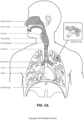
- the respiratory system of the body facilitates gas exchange.
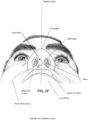
- the nose and mouth form the entrance to the airways of a patient.
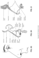
- the airways include a series of branching tubes, which become narrower, shorter and more numerous as they penetrate deeper into the lung.
- the prime function of the lung is gas exchange, allowing oxygen to move from the inhaled air into the venous blood and carbon dioxide to move in the opposite direction.
- the trachea divides into right and left main bronchi, which further divide eventually into terminal bronchioles.
- the bronchi make up the conducting airways, and do not take part in gas exchange. Further divisions of the airways lead to the respiratory bronchioles, and eventually to the alveoli.
- the alveolated region of the lung is where the gas exchange takes place, and is referred to as the respiratory zone. See " Respiratory Physiology", by John B. West, Lippincott Williams & Wilkins, 9th edition published 2012 .
- a range of respiratory disorders exist. Certain disorders may be characterised by particular events, e.g. apneas, hypopneas, and hyperpneas.
- respiratory disorders include Obstructive Sleep Apnea (OSA), Cheyne-Stokes Respiration (CSR), respiratory insufficiency, Obesity Hyperventilation Syndrome (OHS), Chronic Obstructive Pulmonary Disease (COPD), Neuromuscular Disease (NMD) and Chest wall disorders.
- OSA Obstructive Sleep Apnea
- CSR Cheyne-Stokes Respiration
- OOS Obesity Hyperventilation Syndrome
- COPD Chronic Obstructive Pulmonary Disease
- NMD Neuromuscular Disease
- Chest wall disorders examples include Obstructive Sleep Apnea (OSA), Cheyne-Stokes Respiration (CSR), respiratory insufficiency, Obesity Hyperventilation Syndrome (OHS), Chronic Obstructive Pulmonary Disease (COPD), Neuromuscular Disease (NMD) and Chest wall disorders.
- Obstructive Sleep Apnea a form of Sleep Disordered Breathing (SDB), is characterised by events including occlusion or obstruction of the upper air passage during sleep. It results from a combination of an abnormally small upper airway and the normal loss of muscle tone in the region of the tongue, soft palate and posterior oropharyngeal wall during sleep.
- the condition causes the affected patient to stop breathing for periods typically of 30 to 120 seconds in duration, sometimes 200 to 300 times per night. It often causes excessive daytime somnolence, and it may cause cardiovascular disease and brain damage.
- the syndrome is a common disorder, particularly in middle aged overweight males, although a person affected may have no awareness of the problem. See US Patent No. 4,944,310 (Sullivan ).
- CSR Cheyne-Stokes Respiration
- CSR cycles rhythmic alternating periods of waxing and waning ventilation known as CSR cycles.
- CSR is characterised by repetitive de-oxygenation and re-oxygenation of the arterial blood. It is possible that CSR is harmful because of the repetitive hypoxia. In some patients CSR is associated with repetitive arousal from sleep, which causes severe sleep disruption, increased sympathetic activity, and increased afterload. See US Patent No. 6,532,959 (Berthon-Jones ).
- Respiratory failure is an umbrella term for respiratory disorders in which the lungs are unable to inspire sufficient oxygen or exhale sufficient CO 2 to meet the patient's needs. Respiratory failure may encompass some or all of the following disorders.
- a patient with respiratory insufficiency (a form of respiratory failure) may experience abnormal shortness of breath on exercise.
- Obesity Hyperventilation Syndrome is defined as the combination of severe obesity and awake chronic hypercapnia, in the absence of other known causes for hypoventilation. Symptoms include dyspnea, morning headache and excessive daytime sleepiness.
- COPD Chronic Obstructive Pulmonary Disease
- COPD encompasses any of a group of lower airway diseases that have certain characteristics in common. These include increased resistance to air movement, extended expiratory phase of respiration, and loss of the normal elasticity of the lung. Examples of COPD are emphysema and chronic bronchitis. COPD is caused by chronic tobacco smoking (primary risk factor), occupational exposures, air pollution and genetic factors. Symptoms include: dyspnea on exertion, chronic cough and sputum production.
- Neuromuscular Disease is a broad term that encompasses many diseases and ailments that impair the functioning of the muscles either directly via intrinsic muscle pathology, or indirectly via nerve pathology.
- Some NMD patients are characterised by progressive muscular impairment leading to loss of ambulation, being wheelchair-bound, swallowing difficulties, respiratory muscle weakness and, eventually, death from respiratory failure.
- Neuromuscular disorders can be divided into rapidly progressive and slowly progressive: (i) Rapidly progressive disorders: Characterised by muscle impairment that worsens over months and results in death within a few years (e.g.
- ALS Amyotrophic lateral sclerosis
- DMD Duchenne muscular dystrophy
- Variable or slowly progressive disorders Characterised by muscle impairment that worsens over years and only mildly reduces life expectancy (e.g. Limb girdle, Facioscapulohumeral and Myotonic muscular dystrophy).
- Symptoms of respiratory failure in NMD include: increasing generalised weakness, dysphagia, dyspnea on exertion and at rest, fatigue, sleepiness, morning headache, and difficulties with concentration and mood changes.
- Chest wall disorders are a group of thoracic deformities that result in inefficient coupling between the respiratory muscles and the thoracic cage.
- the disorders are usually characterised by a restrictive defect and share the potential of long term hypercapnic respiratory failure.
- Scoliosis and/or kyphoscoliosis may cause severe respiratory failure.
- Symptoms of respiratory failure include: dyspnea on exertion, peripheral oedema, orthopnea, repeated chest infections, morning headaches, fatigue, poor sleep quality and loss of appetite.
- a range of therapies have been used to treat or ameliorate such conditions. Furthermore, otherwise healthy individuals may take advantage of such therapies to prevent respiratory disorders from arising. However, these have a number of shortcomings.
- CPAP Continuous Positive Airway Pressure
- NMV Non-invasive ventilation
- IV Invasive ventilation
- HFT High Flow Therapy
- Respiratory pressure therapy is the application of a supply of air to an entrance to the airways at a controlled target pressure that is nominally positive with respect to atmosphere throughout the patient's breathing cycle (in contrast to negative pressure therapies such as the tank ventilator or cuirass).
- Continuous Positive Airway Pressure (CPAP) therapy has been used to treat Obstructive Sleep Apnea (OSA).
- OSA Obstructive Sleep Apnea
- the mechanism of action is that continuous positive airway pressure acts as a pneumatic splint and may prevent upper airway occlusion, such as by pushing the soft palate and tongue forward and away from the posterior oropharyngeal wall.
- Treatment of OSA by CPAP therapy may be voluntary, and hence patients may elect not to comply with therapy if they find devices used to provide such therapy one or more of: uncomfortable, difficult to use, expensive and aesthetically unappealing.
- Non-invasive ventilation provides ventilatory support to a patient through the upper airways to assist the patient breathing and/or maintain adequate oxygen levels in the body by doing some or all of the work of breathing.
- the ventilatory support is provided via a non-invasive patient interface.
- NIV has been used to treat CSR and respiratory failure, in forms such as OHS, COPD, NMD and Chest Wall disorders. In some forms, the comfort and effectiveness of these therapies may be improved.
- IV Invasive ventilation
- HFT High Flow therapy
- HFT has been used to treat OSA, CSR, respiratory failure, COPD, and other respiratory disorders.
- One mechanism of action is that the high flow rate of air at the airway entrance improves ventilation efficiency by flushing, or washing out, expired CO 2 from the patient's anatomical deadspace.
- HFT is thus sometimes referred to as a deadspace therapy (DST).
- Other benefits may include the elevated warmth and humidification (possibly of benefit in secretion management) and the potential for modest elevation of airway pressures.
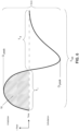
- the treatment flow rate may follow a profile that varies over the respiratory cycle.
- LTOT long-term oxygen therapy
- supplemental oxygen therapy Doctors may prescribe a continuous flow of oxygen enriched gas at a specified oxygen concentration (from 21%, the oxygen fraction in ambient air, to 100%) at a specified flow rate (e.g., 1 litre per minute (LPM), 2 LPM, 3 LPM, etc.) to be delivered to the patient's airway.
- LPM 1 litre per minute
- oxygen therapy may be combined with a respiratory pressure therapy or HFT by adding supplementary oxygen to the pressurised flow of air.
- RPT oxygen is added to respiratory pressure therapy
- HFT oxygen is added to HFT
- HFT with supplementary oxygen oxygen is added to HFT
- These respiratory therapies may be provided by a respiratory therapy system or device. Such systems and devices may also be used to screen, diagnose, or monitor a condition without treating it.
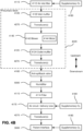
- a respiratory therapy system may comprise a Respiratory Pressure Therapy Device (RPT device), an air circuit, a humidifier, a patient interface, an oxygen source, and data management.
- RPT device Respiratory Pressure Therapy Device
- Another form of therapy system is a mandibular repositioning device.
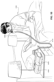
- a patient interface may be used to interface respiratory equipment to its wearer, for example by providing a flow of air to an entrance to the airways.
- the flow of air may be provided via a mask to the nose and/or mouth, a tube to the mouth or a tracheostomy tube to the trachea of a patient.
- the patient interface may form a seal, e.g., with a region of the patient's face, to facilitate the delivery of gas at a pressure at sufficient variance with ambient pressure to effect therapy, e.g., at a positive pressure of about 10 cmH 2 O relative to ambient pressure.
- the patient interface may not include a seal sufficient to facilitate delivery to the airways of a supply of gas at a positive pressure of about 10 cmH 2 O.
- the patient interface is configured to insufflate the nares but specifically to avoid a complete seal.
- a nasal cannula is a nasal cannula.
- Certain other mask systems may be functionally unsuitable for the present field.
- purely ornamental masks may be unable to maintain a suitable pressure.
- Mask systems used for underwater swimming or diving may be configured to guard against ingress of water from an external higher pressure, but not to maintain air internally at a higher pressure than ambient.
- Certain masks may be clinically unfavourable for the present technology e.g. if they block airflow via the nose and only allow it via the mouth.
- Certain masks may be uncomfortable or impractical for the present technology if they require a patient to insert a portion of a mask structure in their mouth to create and maintain a seal via their lips.
- Certain masks may be impractical for use while sleeping, e.g. for sleeping while lying on one's side in bed with a head on a pillow.
- the design of a patient interface presents a number of challenges.
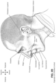
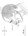
- the face has a complex three-dimensional shape.
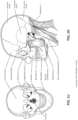
- the size and shape of noses and heads varies considerably between individuals. Since the head includes bone, cartilage and soft tissue, different regions of the face respond differently to mechanical forces.
- the jaw or mandible may move relative to other bones of the skull. The whole head may move during the course of a period of respiratory therapy.
- masks suffer from being one or more of obtrusive, aesthetically undesirable, costly, poorly fitting, difficult to use, and uncomfortable especially when worn for long periods of time or when a patient is unfamiliar with a system. Wrongly sized masks can give rise to reduced compliance, reduced comfort and poorer patient outcomes.
- Masks designed solely for aviators, masks designed as part of personal protection equipment (e.g. filter masks), SCUBA masks, or for the administration of anaesthetics may be tolerable for their original application, but nevertheless such masks may be undesirably uncomfortable to be worn for extended periods of time, e.g., several hours. This discomfort may lead to a reduction in patient compliance with therapy. This is even more so if the mask is to be worn during sleep.
- CPAP therapy is highly effective to treat certain respiratory disorders, provided patients comply with therapy. If a mask is uncomfortable, or difficult to use a patient may not comply with therapy. Since it is often recommended that a patient regularly wash their mask, if a mask is difficult to clean (e.g., difficult to assemble or disassemble), patients may not clean their mask and this may impact on patient compliance.
- a mask for other applications may not be suitable for use in treating sleep disordered breathing
- a mask designed for use in treating sleep disordered breathing may be suitable for other applications.
- patient interfaces for delivery of CPAP during sleep form a distinct field.
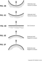
- Patient interfaces may include a seal-forming structure. Since it is in direct contact with the patient's face, the shape and configuration of the seal-forming structure can have a direct impact the effectiveness and comfort of the patient interface.
- a patient interface may be partly characterised according to the design intent of where the seal-forming structure is to engage with the face in use.
- a seal-forming structure may comprise a first sub-portion to form a seal around the left naris and a second sub-portion to form a seal around the right naris.
- a seal-forming structure may comprise a single element that surrounds both nares in use. Such single element may be designed to for example overlay an upper lip region and a nasal bridge region of a face.
- a seal-forming structure may comprise an element that surrounds a mouth region in use, e.g. by forming a seal on a lower lip region of a face.
- a seal-forming structure may comprise a single element that surrounds both nares and a mouth region in use.
- These different types of patient interfaces may be known by a variety of names by their manufacturer including nasal masks, full-face masks, nasal pillows, nasal puffs and oro-nasal masks.
- a seal-forming structure that may be effective in one region of a patient's face may be inappropriate in another region, e.g. because of the different shape, structure, variability and sensitivity regions of the patient's face.
- a seal on swimming goggles that overlays a patient's forehead may not be appropriate to use on a patient's nose.
- Certain seal-forming structures may be designed for mass manufacture such that one design fit and be comfortable and effective for a wide range of different face shapes and sizes. To the extent to which there is a mismatch between the shape of the patient's face, and the seal-forming structure of the mass-manufactured patient interface, one or both must adapt in order for a seal to form.
- seal-forming structure extends around the periphery of the patient interface, and is intended to seal against the patient's face when force is applied to the patient interface with the seal-forming structure in confronting engagement with the patient's face.
- the seal-forming structure may include an air or fluid filled cushion, or a moulded or formed surface of a resilient seal element made of an elastomer such as a rubber.
- seal-forming structure incorporates a flap seal of thin material positioned about the periphery of the mask so as to provide a self-sealing action against the face of the patient when positive pressure is applied within the mask.
- flap seal of thin material positioned about the periphery of the mask so as to provide a self-sealing action against the face of the patient when positive pressure is applied within the mask.
- additional force may be required to achieve a seal, or the mask may leak.
- shape of the seal-forming structure does not match that of the patient, it may crease or buckle in use, giving rise to leaks.
- seal-forming structure may comprise a friction-fit element, e.g. for insertion into a naris, however some patients find these uncomfortable.
- seal-forming structure may use adhesive to achieve a seal. Some patients may find it inconvenient to constantly apply and remove an adhesive to their face.
- nasal pillow is found in the Adam Circuit manufactured by Puritan Bennett.
- Another nasal pillow, or nasal puff is the subject of US Patent 4,782,832 (Trimble et al. ), assigned to Puritan-Bennett Corporation.
- ResMed Limited has manufactured the following products that incorporate nasal pillows: SWIFT TM nasal pillows mask, SWIFT TM II nasal pillows mask, SWIFT TM LT nasal pillows mask, SWIFT TM FX nasal pillows mask and MIRAGE LIBERTY TM full-face mask.
- a seal-forming structure of a patient interface used for positive air pressure therapy is subject to the corresponding force of the air pressure to disrupt a seal.
- a variety of techniques have been used to position the seal-forming structure, and to maintain it in sealing relation with the appropriate portion of the face.
- Another technique is the use of one or more straps and/or stabilising harnesses. Many such harnesses suffer from being one or more of ill-fitting, bulky, uncomfortable and awkward to use.
- a respiratory pressure therapy (RPT) device may be used individually or as part of a system to deliver one or more of a number of therapies described above, such as by operating the device to generate a flow of air for delivery to an interface to the airways.
- the flow of air may be pressure-controlled (for respiratory pressure therapies) or flow-controlled (for flow therapies such as HFT).
- RPT devices may also act as flow therapy devices. Examples of RPT devices include a CPAP device and a ventilator.
- Air pressure generators are known in a range of applications, e.g. industrial-scale ventilation systems. However, air pressure generators for medical applications have particular requirements not fulfilled by more generalised air pressure generators, such as the reliability, size and weight requirements of medical devices. In addition, even devices designed for medical treatment may suffer from shortcomings, pertaining to one or more of: comfort, noise, ease of use, efficacy, size, weight, manufacturability, cost, and reliability.
- RPT device used for treating sleep disordered breathing is the S9 Sleep Therapy System, manufactured by ResMed Limited.
- RPT device is a ventilator.
- Ventilators such as the ResMed Stellar TM Series of Adult and Paediatric Ventilators may provide support for invasive and non-invasive non-dependent ventilation for a range of patients for treating a number of conditions such as but not limited to NMD, OHS and COPD.
- the ResMed Elo TM 150 ventilator and ResMed VS III TM ventilator may provide support for invasive and non-invasive dependent ventilation suitable for adult or paediatric patients for treating a number of conditions. These ventilators provide volumetric and barometric ventilation modes with a single or double limb circuit.
- RPT devices typically comprise a pressure generator, such as a motor-driven blower or a compressed gas reservoir, and are configured to supply a flow of air to the airway of a patient. In some cases, the flow of air may be supplied to the airway of the patient at positive pressure.
- the outlet of the RPT device is connected via an air circuit to a patient interface such as those described above.
- the designer of a device may be presented with an infinite number of choices to make. Design criteria often conflict, meaning that certain design choices are far from routine or inevitable. Furthermore, the comfort and efficacy of certain aspects may be highly sensitive to small, subtle changes in one or more parameters.
- An air circuit is a conduit or a tube constructed and arranged to allow, in use, a flow of air to travel between two components of a respiratory therapy system such as the RPT device and the patient interface.
- a respiratory therapy system such as the RPT device and the patient interface.
- a single limb air circuit is used for both inhalation and exhalation.
- a range of artificial humidification devices and systems are known, however they may not fulfil the specialised requirements of a medical humidifier.
- Medical humidifiers are used to increase humidity and/or temperature of the flow of air in relation to ambient air when required, typically where the patient may be asleep or resting (e.g. at a hospital).
- a medical humidifier for bedside placement may be small.
- a medical humidifier may be configured to only humidify and/or heat the flow of air delivered to the patient without humidifying and/or heating the patient's surroundings.
- Room-based systems e.g. a sauna, an air conditioner, or an evaporative cooler
- medical humidifiers may have more stringent safety constraints than industrial humidifiers
- Oxygen concentrators have been in use for about 50 years to supply oxygen for respiratory therapy. Traditional oxygen concentrators have been bulky and heavy making ordinary ambulatory activities with them difficult and impractical. Recently, companies that manufacture large stationary oxygen concentrators began developing portable oxygen concentrators (POCs). The advantage of POCs is that they can produce a theoretically endless supply of oxygen. In order to make these devices small for mobility, the various systems necessary for the production of oxygen enriched gas are condensed. POCs seek to utilize their produced oxygen as efficiently as possible, in order to minimise weight, size, and power consumption. This may be achieved by delivering the oxygen as series of pulses or "boli", each bolus timed to coincide with the start of inspiration. This therapy mode is known as pulsed or demand (oxygen) delivery (POD), in contrast with traditional continuous flow delivery more suited to stationary oxygen concentrators.
- POD pulsed or demand (oxygen) delivery
- a compliance rule for CPAP therapy is that a patient, in order to be deemed compliant, is required to use the RPT device for at least four hours a night for at least 21 of 30 consecutive days.
- a provider of the RPT device such as a health care provider, may manually obtain data describing the patient's therapy using the RPT device, calculate the usage over a predetermined time period, and compare with the compliance rule. Once the health care provider has determined that the patient has used their RPT device according to the compliance rule, the health care provider may notify a third party that the patient is compliant.
- a mandibular repositioning device (MRD) or mandibular advancement device (MAD) is one of the treatment options for sleep apnea and snoring. It is an adjustable oral appliance available from a dentist or other supplier that holds the lower jaw (mandible) in a forward position during sleep.
- the MRD is a removable device that a patient inserts into their mouth prior to going to sleep and removes following sleep. Thus, the MRD is not designed to be worn all of the time.
- the MRD may be custom made or produced in a standard form and includes a bite impression portion designed to allow fitting to a patient's teeth. This mechanical protrusion of the lower jaw expands the space behind the tongue, puts tension on the pharyngeal walls to reduce collapse of the airway and diminishes palate vibration.
- a mandibular advancement device may comprise an upper splint that is intended to engage with or fit over teeth on the upper jaw or maxilla and a lower splint that is intended to engage with or fit over teeth on the upper jaw or mandible.
- the upper and lower splints are connected together laterally via a pair of connecting rods.
- the pair of connecting rods are fixed symmetrically on the upper splint and on the lower splint.
- the length of the connecting rods is selected such that when the MRD is placed in a patient's mouth the mandible is held in an advanced position.
- the length of the connecting rods may be adjusted to change the level of protrusion of the mandible.
- a dentist may determine a level of protrusion for the mandible that will determine the length of the connecting rods.
- MRDs are structured to push the mandible forward relative to the maxilla while other MADs, such as the ResMed Narval CC TM MRD are designed to retain the mandible in a forward position.
- This device also reduces or minimises dental and temporo-mandibular joint (TMJ) side effects. Thus, it is configured to minimises or prevent any movement of one or more of the teeth.
- Some forms of treatment systems may include a vent to allow the washout of exhaled carbon dioxide.
- the vent may allow a flow of gas from an interior space of a patient interface, e.g., the plenum chamber, to an exterior of the patient interface, e.g., to ambient.
- the vent may comprise an orifice and gas may flow through the orifice in use of the mask. Many such vents are noisy. Others may become blocked in use and thus provide insufficient washout. Some vents may be disruptive of the sleep of a bed partner 1100 of the patient 1000, e.g. through noise or focussed airflow.
- ResMed Limited has developed a number of improved mask vent technologies. See International Patent Application Publication No. WO 1998/034665 ; International Patent Application Publication No. WO 2000/078381 ; US Patent No. 6,581,594 ; US Patent Application Publication No. US 2009/0050156 ; US Patent Application Publication No. 2009/0044808 .
- Object A-weighted sound pressure dB(A) Notes Vacuum cleaner: Nilfisk 68 ISO 3744 at 1m distance Walter Broadly Litter Hog: B+ Grade Conversational speech 60 1m distance Average home 50 Quiet library 40 Quiet bedroom at night 30 Background in TV studio 20
- PSG Polysomnography
- EEG electroencephalography
- ECG electrocardiography
- EOG electrooculograpy
- EMG electromyography
- PSG for sleep disordered breathing has involved two nights of observation of a patient in a clinic, one night of pure diagnosis and a second night of titration of treatment parameters by a clinician.
- PSG is therefore expensive and inconvenient. In particular it is unsuitable for home screening / diagnosis / monitoring of sleep disordered breathing.
- Screening and diagnosis generally describe the identification of a condition from its signs and symptoms. Screening typically gives a true / false result indicating whether or not a patient's SDB is severe enough to warrant further investigation, while diagnosis may result in clinically actionable information. Screening and diagnosis tend to be one-off processes, whereas monitoring the progress of a condition can continue indefinitely. Some screening / diagnosis systems are suitable only for screening / diagnosis, whereas some may also be used for monitoring.
- Clinical experts may be able to screen, diagnose, or monitor patients adequately based on visual observation of PSG signals. However, there are circumstances where a clinical expert may not be available, or a clinical expert may not be affordable. Different clinical experts may disagree on a patient's condition. In addition, a given clinical expert may apply a different standard at different times.
- the invention is defined in the appended independent claim 1. Preferred embodiments are matter of the dependent claims.
- the present technology is directed towards providing medical devices used in the screening, diagnosis, monitoring, amelioration, treatment, or prevention of respiratory disorders having one or more of improved comfort, cost, efficacy, ease of use and manufacturability.
- a first aspect of the present technology relates to apparatus used in the screening, diagnosis, monitoring, amelioration, treatment or prevention of a respiratory disorder.
- Another aspect of the present technology relates to methods used in the screening, diagnosis, monitoring, amelioration, treatment or prevention of a respiratory disorder.
- An aspect of certain forms of the present technology is to provide methods and/or apparatus that improve the compliance of patients with respiratory therapy.
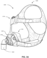
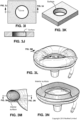
- a patient interface comprising: a plenum chamber; a seal-forming structure; and a positioning and stabilising structure.
- a vent structure may also be included.
- a patient interface comprising: a plenum chamber pressurisable to a therapeutic pressure of at least 4 cmH 2 O above ambient air pressure; a seal-forming structure constructed and arranged to seal with a region of the patient's face surrounding an entrance to the patient's airways; a positioning and stabilising structure to provide a force to hold the seal-forming structure in a therapeutically effective position on the patient's head; and a vent structure to allow a continuous flow of gases exhaled by the patient from an interior of the plenum chamber to ambient.
- the patient interface may also be configured to allow the patient to breath from ambient through their mouth in the absence of a flow of pressurised air through the plenum chamber inlet port, or the patient interface is configured to leave the patient's mouth uncovered.
- a patient interface comprising: a plenum chamber pressurisable to a therapeutic pressure of at least 4 cmH 2 O above ambient air pressure, said plenum chamber including a plenum chamber inlet port sized and structured to receive a flow of air at the therapeutic pressure for breathing by a patient; a seal-forming structure constructed and arranged to seal with a region of the patient's face surrounding an entrance to the patient's airways, said seal-forming structure having a hole therein such that the flow of air at said therapeutic pressure is delivered to at least the patient's nares, the seal-forming structure constructed and arranged to maintain said therapeutic pressure in the plenum chamber throughout the patient's respiratory cycle in use; a positioning and stabilising structure to provide a force to hold the seal-forming structure in a therapeutically effective position on the patient's head, the positioning and stabilising structure comprising a tie, the tie being constructed and arranged so that at least a portion overlies a region of the patient's head superior to an otobasion superior of the patient's
- a patient interface comprising: a plenum chamber pressurisable to a therapeutic pressure; a seal-forming structure constructed and arranged to seal with a region of the patient's face; a positioning and stabilising structure configured to provide a force to hold the seal-forming structure in a therapeutically effective position on the patient's head; a vent structure configured to allow a continuous flow of gases exhaled by the patient from an interior of the plenum chamber to ambient; and a material configured to adsorb water vapour from gases exhaled by the patient and desorb water vapour into the flow of air at the therapeutic pressure.
- the patient interface may be configured to leave the patient's mouth uncovered, or if the seal-forming structure is configured to seal around the patient's nose and mouth, the patient interface is configured to allow the patient to breath from ambient in the absence of a flow of pressurised air.
- a patient interface comprising: a plenum chamber pressurisable to a therapeutic pressure of at least 4 cmH2O above ambient air pressure by a flow of air at the therapeutic pressure for breathing by a patient; a seal-forming structure constructed and arranged to seal with a region of the patient's face at least partly surrounding an entrance to the patient's airways, said seal-forming structure having a hole therein such that the flow of air at said therapeutic pressure is delivered to at least the patient's nares, the seal-forming structure constructed and arranged to maintain said therapeutic pressure in the plenum chamber throughout the patient's respiratory cycle in use; a positioning and stabilising structure configured to provide a force to hold the seal-forming structure in a therapeutically effective position on the patient's head; a vent structure configured to allow a continuous flow of gases exhaled by the patient from an interior of the plenum chamber to ambient, said vent structure being sized and shaped to maintain the therapeutic pressure in the plenum chamber in use; and a material configured to
- a patient interface comprising: a plenum chamber pressurisable to a therapeutic pressure of at least 4 cmH2O above ambient air pressure by a flow of air at the therapeutic pressure for breathing by a patient, the plenum chamber further comprising two plenum chamber connectors positioned on corresponding lateral sides of the plenum chamber and configured to receive the flow of air at the therapeutic pressure; a seal-forming structure connected to the plenum chamber, the seal-forming structure being constructed and arranged to seal with a region of the patient's face at least partly surrounding an entrance to the patient's airways, said seal-forming structure having a hole therein such that the flow of air at said therapeutic pressure is delivered to at least the patient's nares, the seal-forming structure constructed and arranged to maintain said therapeutic pressure in the plenum chamber throughout the patient's respiratory cycle in use; a positioning and stabilising structure configured to provide a force to hold the seal-forming structure in a therapeutically effective position on the patient's head, the positioning and stabilising
- the material may comprise foam or paper
- the material may comprise a salt applied to a surface of the material
- the material may be removable from the plenum chamber
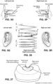
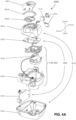
- the plenum chamber may comprise a main frame and a removable frame that is removable from the main frame
- the material may be attached to the removable frame such that the removable frame and the material are removable from the main frame together
- the removable frame may comprise vent holes
- the vent holes may include two groups of vent holes, each of the groups of vent holes being positioned proximal to a corresponding lateral side of the removable frame
- the main frame may comprise the plenum chamber connectors, each of the plenum chamber connectors being positioned on a corresponding lateral side of the main frame
- the main frame may comprise vent holes
- the vent holes may include two groups of vent holes, each of the groups of vent holes being positioned proximal to a corresponding lateral
- a patient interface comprising: a plenum chamber pressurisable to a therapeutic pressure; a seal-forming structure connected to the plenum chamber, the seal-forming structure being constructed and arranged to seal with a region of the patient's face; a positioning and stabilising structure configured to provide a force to hold the seal-forming structure in a therapeutically effective position on the patient's head; a vent structure configured to allow a continuous flow of gases exhaled by the patient from an interior of the plenum chamber to ambient; and a material configured to adsorb water vapour from gases exhaled by the patient and desorb water vapour into the flow of air at the therapeutic pressure, the material being attached to the plenum chamber such that the plenum chamber holds the material in a predetermined shape.
- a patient interface comprising: a plenum chamber pressurisable to a therapeutic pressure of at least 4 cmH2O above ambient air pressure by a flow of air at the therapeutic pressure for breathing by a patient; a seal-forming structure connected to the plenum chamber, the seal-forming structure being constructed and arranged to seal with a region of the patient's face at least partly surrounding an entrance to the patient's airways, said seal-forming structure having a hole therein such that the flow of air at said therapeutic pressure is delivered to at least the patient's nares, the seal-forming structure being constructed and arranged to maintain said therapeutic pressure in the plenum chamber throughout the patient's respiratory cycle in use; a positioning and stabilising structure configured to provide a force to hold the seal-forming structure in a therapeutically effective position on the patient's head; a vent structure configured to allow a continuous flow of gases exhaled by the patient from an interior of the plenum chamber to ambient, said vent structure being sized and shaped to maintain the therapeutic pressure
- the material may comprise foam or paper
- the material may comprise a salt applied to a surface of the material
- the material may be removable from the plenum chamber
- the plenum chamber may comprise a main frame and a removable frame that is removable from the main frame
- the material may be attached to the removable frame such that the removable frame and the material are removable from the main frame together
- the removable frame may comprise vent holes
- the vent holes may include two groups of vent holes, each of the groups of vent holes being positioned proximal to a corresponding lateral side of the removable frame
- the main frame may comprise the plenum chamber connectors, each of the plenum chamber connectors being positioned on a corresponding lateral side of the main frame
- the main frame may comprise vent holes
- the vent holes may include two groups of vent holes, each of the groups of vent holes being positioned proximal to a corresponding lateral
- a respiratory pressure therapy (RPT) system may include the patient interface of any one of the preceding aspects; a respiratory pressure therapy (RPT) device configured to generate the flow of air at the therapeutic pressure; and an air circuit configured to connect the RPT device and the patient interface to direct the flow of air at the therapeutic pressure from the RPT device to the patient interface, wherein the RPT system does not include a humidifier.
- RPT respiratory pressure therapy
- Another aspect of one form of the present technology is a patient interface that is moulded or otherwise constructed with a perimeter shape which is complementary to that of an intended wearer.
- An aspect of one form of the present technology is a method of manufacturing apparatus.
- An aspect of certain forms of the present technology is a medical device that is easy to use, e.g. by a person who does not have medical training, by a person who has limited dexterity, vision or by a person with limited experience in using this type of medical device.
- An aspect of one form of the present technology is a portable RPT device that may be carried by a person, e.g., around the home of the person.
- An aspect of one form of the present technology is a patient interface that may be washed in a home of a patient, e.g., in soapy water, without requiring specialised cleaning equipment.
- An aspect of one form of the present technology is a humidifier tank that may be washed in a home of a patient, e.g., in soapy water, without requiring specialised cleaning equipment.
- the methods, systems, devices and apparatus described may be implemented so as to improve the functionality of a processor, such as a processor of a specific purpose computer, respiratory monitor and/or a respiratory therapy apparatus. Moreover, the described methods, systems, devices and apparatus can provide improvements in the technological field of automated management, monitoring and/or treatment of respiratory conditions, including, for example, sleep disordered breathing.
- portions of the aspects may form sub-aspects of the present technology.
- various ones of the sub-aspects and/or aspects may be combined in various manners and also constitute additional aspects or sub-aspects of the present technology.
- Fig. 6 shows a model typical breath waveform of a person while sleeping.
- the present technology comprises a method for treating a respiratory disorder comprising applying positive pressure to the entrance of the airways of a patient 1000.
- a supply of air at positive pressure is provided to the nasal passages of the patient via one or both nares.
- mouth breathing is limited, restricted or prevented.
- the present technology comprises a respiratory therapy system for treating a respiratory disorder.
- the a respiratory therapy system may comprise an RPT device 4000 for supplying a flow of air to the patient 1000 via an air circuit 4170 and a patient interface 3000 or 3800.
- a non-invasive patient interface 3000 in accordance with one aspect of the present technology comprises the following functional aspects: a seal-forming structure 3100, a plenum chamber 3200, a positioning and stabilising structure 3300, a vent 3400, one form of connection port 3600 for connection to air circuit 4170, and a forehead support 3700.
- a functional aspect may be provided by one or more physical components.
- one physical component may provide one or more functional aspects.
- the seal-forming structure 3100 is arranged to surround an entrance to the airways of the patient so as to maintain positive pressure at the entrance(s) to the airways of the patient 1000.
- the sealed patient interface 3000 is therefore suitable for delivery of positive pressure therapy.
- An unsealed patient interface 3800 in the form of a nasal cannula, includes nasal prongs 3810a, 3810b which can deliver air to respective nares of the patient 1000 via respective orifices in their tips. Such nasal prongs do not generally form a seal with the inner or outer skin surface of the nares.
- the air to the nasal prongs may be delivered by one or more air supply lumens 3820a, 3820b that are coupled with the nasal cannula 3800.
- the lumens 3820a, 3820b lead from the nasal cannula 3800 to a respiratory therapy device via an air circuit.
- the unsealed patient interface 3800 is particularly suitable for delivery of flow therapies, in which the RPT device generates the flow of air at controlled flow rates rather than controlled pressures.
- the "vent" at the unsealed patient interface 3800, through which excess airflow escapes to ambient, is the passage between the end of the prongs 3810a and 3810b of the cannula 3800 via the patient's nares to atmosphere.
- a patient interface is unable to comfortably deliver a minimum level of positive pressure to the airways, the patient interface may be unsuitable for respiratory pressure therapy.
- the patient interface 3000 in accordance with one form of the present technology is constructed and arranged to be able to provide a supply of air at a positive pressure of at least 6 cmH 2 O with respect to ambient.
- the patient interface 3000 in accordance with one form of the present technology is constructed and arranged to be able to provide a supply of air at a positive pressure of at least 10 cmH 2 O with respect to ambient.
- the patient interface 3000 in accordance with one form of the present technology is constructed and arranged to be able to provide a supply of air at a positive pressure of at least 20 cmH 2 O with respect to ambient.
- a seal-forming structure 3100 provides a target seal-forming region, and may additionally provide a cushioning function.
- the target seal-forming region is a region on the seal-forming structure 3100 where sealing may occur.
- the region where sealing actually occurs- the actual sealing surface- may change within a given treatment session, from day to day, and from patient to patient, depending on a range of factors including for example, where the patient interface was placed on the face, tension in the positioning and stabilising structure and the shape of a patient's face.
- the target seal-forming region is located on an outside surface of the seal-forming structure 3100.
- the seal-forming structure 3100 is constructed from a biocompatible material, e.g. silicone rubber.
- a seal-forming structure 3100 in accordance with the present technology may be constructed from a soft, flexible, resilient material such as silicone.
- a system comprising more than one a seal-forming structure 3100, each being configured to correspond to a different size and/or shape range.
- the system may comprise one form of a seal-forming structure 3100 suitable for a large sized head, but not a small sized head and another suitable for a small sized head, but not a large sized head.
- the seal-forming structure includes a sealing flange utilizing a pressure assisted sealing mechanism.
- the sealing flange can readily respond to a system positive pressure in the interior of the plenum chamber 3200 acting on its underside to urge it into tight sealing engagement with the face.
- the pressure assisted mechanism may act in conjunction with elastic tension in the positioning and stabilising structure.
- the seal-forming structure 3100 comprises a sealing flange and a support flange.
- the sealing flange comprises a relatively thin member with a thickness of less than about 1mm, for example about 0.25mm to about 0.45mm, which extends around the perimeter of the plenum chamber 3200.
- Support flange may be relatively thicker than the sealing flange.
- the support flange is disposed between the sealing flange and the marginal edge of the plenum chamber 3200, and extends at least part of the way around the perimeter.
- the support flange is or includes a springlike element and functions to support the sealing flange from buckling in use.
- the seal-forming structure may comprise a compression sealing portion or a gasket sealing portion.
- the compression sealing portion, or the gasket sealing portion is constructed and arranged to be in compression, e.g. as a result of elastic tension in the positioning and stabilising structure.
- the seal-forming structure comprises a tension portion.
- the tension portion is held in tension, e.g. by adjacent regions of the sealing flange.
- a seal-forming structure may comprise one or more of a pressure-assisted sealing flange, a compression sealing portion, a gasket sealing portion, a tension portion, and a portion having a tacky or adhesive surface.
- the non-invasive patient interface 3000 comprises a seal-forming structure that forms a seal in use on a nose bridge region or on a nose-ridge region of the patient's face.
- the seal-forming structure includes a saddle-shaped region constructed to form a seal in use on a nose bridge region or on a nose-ridge region of the patient's face.
- the non-invasive patient interface 3000 comprises a seal-forming structure that forms a seal in use on an upper lip region (that is, the lip superior) of the patient's face.
- the seal-forming structure includes a saddle-shaped region constructed to form a seal in use on an upper lip region of the patient's face.
- the non-invasive patient interface 3000 comprises a seal-forming structure that forms a seal in use on a chin-region of the patient's face.
- the seal-forming structure includes a saddle-shaped region constructed to form a seal in use on a chin-region of the patient's face.
- the seal-forming structure that forms a seal in use on a forehead region of the patient's face may cover the eyes in use.
- the seal-forming structure of the non-invasive patient interface 3000 comprises a pair of nasal puffs, or nasal pillows, each nasal puff or nasal pillow being constructed and arranged to form a seal with a respective naris of the nose of a patient.
- Nasal pillows in accordance with an aspect of the present technology include: a frusto-cone, at least a portion of which forms a seal on an underside of the patient's nose, a stalk, a flexible region on the underside of the frusto-cone and connecting the frusto-cone to the stalk.
- the structure to which the nasal pillow of the present technology is connected includes a flexible region adjacent the base of the stalk.
- the flexible regions can act in concert to facilitate a universal joint structure that is accommodating of relative movement both displacement and angular of the frusto-cone and the structure to which the nasal pillow is connected.
- the frusto-cone may be axially displaced towards the structure to which the stalk is connected.
- Figs. 7-15 show a seal-forming structure 3100 according to an example of the present technology.
- the examples of seal-forming structure 3100 may be considered nasal cradle cushions and are intended to provide a flow of pressurised gas to the patient's nares by sealing against at least the underside of the patient's nose.
- the exemplary seal-forming structures 3100 will engage the patient's face below the bridge of the nose and some examples, depending on the size and shape of the patient's nose, may engage the patient's nose below the pronasale.
- the exemplary seal-forming structures 3100 will also engage the patient's face at least above the upper vermillion.
- the exemplary seal-forming structures 3100 may seal against the patient's lip superior in use.
- the patient's mouth may remain uncovered by the seal-forming structure 3100 of the depicted examples such that the patient may breathe freely, i.e., directly to atmosphere, without interference from the seal-forming structure 3100.
- Examples of a nasal cradle cushion may include a superior saddle or concave region that has positive curvature across the cushion.
- a nasal cradle cushion may be understood to have a single target seal forming region or surface, whereas a pillows cushion may have two target seal forming regions (one for each naris).
- Cradle cushions may also have a posterior wall that contacts the patient's lip superior and an upper, central, surface contacts the underside of the patient's nose. These two surfaces on the patient's face may form a nasolabial angle between them (see Fig. 2E ).
- a cradle cushion may be shaped to have a nasolabial angle within the range of 90 degrees to 120 degrees.
- the exemplary seal-forming structures 3100 may also be shaped and dimensioned such that no portion of the seal-forming structure 3100 enters into the patient's nares during use.
- the plenum chamber 3200 has a perimeter that is shaped to be complementary to the surface contour of the face of an average person in the region where a seal will form in use. In use, a marginal edge of the plenum chamber 3200 is positioned in close proximity to an adjacent surface of the face. Actual contact with the face is provided by the seal-forming structure 3100.
- the seal-forming structure 3100 may extend in use about the entire perimeter of the plenum chamber 3200. In some forms, the plenum chamber 3200 and the seal-forming structure 3100 are formed from a single homogeneous piece of material.
- the plenum chamber 3200 does not cover the eyes of the patient in use. In other words, the eyes are outside the pressurised volume defined by the plenum chamber. Such forms tend to be less obtrusive and / or more comfortable for the wearer, which can improve compliance with therapy.
- the plenum chamber 3200 is constructed from a transparent material, e.g. a transparent polycarbonate.
- a transparent material can reduce the obtrusiveness of the patient interface, and help improve compliance with therapy.
- the use of a transparent material can aid a clinician to observe how the patient interface is located and functioning.
- the plenum chamber 3200 is constructed from a translucent material.
- a translucent material can reduce the obtrusiveness of the patient interface, and help improve compliance with therapy.
- Each plenum chamber connector 3214 in these examples may include a notch 3216 that is connected to a clip projection of a clip with a snap-fit. Each plenum chamber connector 3214 may be split to form a slot 3220 to allow deformation within the clip during connection. Each clip may be joined to a clip overmold, which is an intermediate component between the end 3314 of the positioning and stabilising structure 3300. Surrounding the ends 3314 of the positioning and stabilising structure 3300 may be a lip that seals with the plenum chamber connector 3214.
- the lip may surround the entire opening at the end 3314 of the positioning and stabilising structure 3300 to ensure a complete and gas tight seal against the plenum chamber connector 3214 so that the entire flow of pressurised gas passing through the positioning and stabilising structure 3300 reaches the patient via the plenum chamber 3200 and the seal-forming structure 3100.
- the plenum chamber connector 3214 may also include a chamfered edge 3218 that provides a smooth transition into the end 3314 of the positioning and stabilising structure 3300.
- the seal-forming structure 3100 may be constructed from a relatively resilient material, such as an elastomer like silicone as described above, while the plenum chamber 3200 may be constructed from a relatively rigid material, such as polycarbonate.
- the seal-forming structure 3100 may be molded onto the plenum chamber 3200, and this molded connection may be permanent.
- the seal-forming structure 3100 and the plenum chamber 3200 may be formed separately so as to be removably attachable to one another, e.g., by the patient for cleaning or replacement of the seal-forming structure 3100.
- the seal-forming structure 3100 and the plenum chamber 3200 may each be constructed from a relatively resilient material, such as an elastomer like silicone, and in further examples both components may be molded to form a single, homogeneous piece of the relatively resilient material.
- Figs. 16-23 show examples of a seal-forming structure 3100 and a plenum chamber 3200, as well as a heat and moisture exchanger (HME), according to the present technology illustrating also aspects of the present invention.
- the HME may be in the form of an HME material 3900.
- the HME material 3900 may be positioned within the plenum chamber 3200 as can be seen in the cross-sectional views.
- the plenum chamber 3200 may be a two-part structure that includes a main frame 3202 and a removable frame 3204 that is removable from the main frame 3202.
- the HME material 3900 may be attached to the removable frame 3204 so that the HME material 3900 can be removed from the plenum chamber 3200 with the removable frame 3204, as will be described further below.
- Fig. 24 shows the removable frame 3204 removed from the main frame 3202 while the HME material 3900 remains to depict the position of the HME material 3900 within the plenum chamber 3200.
- Fig. 25 shows the removable frame 3204 and the HME material 3900 removed from the main frame 3202 to depict the interior of the seal-forming structure 3100 and the plenum chamber 3200.
- Figs. 22 and 26-31 also illustrate aspects of the present invention and show a first variation of the HME material 3900.
- Figs. 23 and 32-38 show a second variation of the HME material 3900.
- the first variation of the HME material 3900 is relatively thinner, i.e., the dimension between an anterior surface 3906 and a posterior surface 3904 of the HME material 3900, than the second variation.
- the cross-sectional views of Figs. 22 and 23 show that each variation of the HME material 3900 has a constant thickness, i.e., the dimension between the anterior surface 3906 and the posterior surface 3904, from lateral surface 3912 to lateral surface 3914.
- the thickness dimension can vary at different points along the HME material 3900 between lateral surfaces 3912, 3914 as needed to fit within the plenum chamber 3200.
- the height i.e., the dimension between a superior surface 3908 and an inferior surface 3910, is lowest at the medial or central portion 3916 of the HME material 3900 and increases in each lateral direction towards a respective one of the lateral surfaces 3912, 3914.
- a wall 3226 of the removable frame 3204 can be seen with a height that is lowest at a medial portion 3203 and that increase toward respective lateral portions 3205.
- the main frame anterior hole 3206 where the removable frame 3204 removably attaches to the main frame 3202, may also be shaped and dimensioned to correspond to the wall 3226 of the removable frame.
- the HME material 3900 may have a height at various points along its length such that it can fit through the main frame anterior hole 3206 when the removable frame 3204 removably attaches to the main frame 3202.
- the HME material 3900 may also be a material resilient such that the HME material 3900 can deform, as needed, when inserted into the main frame 3202.
- the height dimension of the wall 3226 of the removable frame 3204 and the HME material 3900 can vary at different points between lateral portions 3205 and lateral surfaces 3912, 3914, respectively, as needed to fit within the plenum chamber 3200.
- the HME material 3900 may have a constant height between lateral surfaces 3912, 3914.
- the first variation of the HME material 3900 includes a notched portion 3902 at each lateral side of the posterior surface 3904, while the second variation of the HME material 3900 does not have notched portions 3902.
- the relatively thinner HME material 3900 could have no notched portions 3902 and the relatively thicker HME material 3900 could have notched portions 3902.
- the notched portions 3902 may be included to provide more clearance for the seal-forming structure 3100 and the plenum chamber 3200 when the HME material 3900 is installed in the plenum chamber 3200.
- a relatively thinner material, as in the first variation may provide more clearance from the seal-forming structure 3100 and the patient's face.
- Figs. 39-42 show the removable frame 3204 in isolation.
- the vents 3400 are shown, which may be formed by two groups of vent holes, each positioned proximal to a corresponding lateral end of the removable frame 3204.
- the removable frame 3204 may also include supports 3210, and the HME material 3900 may be attached to these supports 3210.
- U.S. Publication No. 2016/0175552 A1 discloses positioning an HME within a nasal mask, such as the RESMEDO AirFit TM N20, or a full-face mask, such as the RESMED ® AirFit TM F20. Due to the configuration of these patient interfaces, there may be adequate space within such patient interfaces for an HME of sufficient size to provide a desired level of performance (i.e., heat and moisture exchange).
- more compact patient interfaces such as nasal cradle masks, like the RESMED ® AirFit TM N30i, nasal pillows masks, like the RESMED ® AirFit TM P30i or the RESMEDO AirFit TM P10, and ultra-compact full-face masks, like the RESMEDO AirFit TM F30, may have less volume in the plenum chamber 3200 and as such the size, shape, position, and orientation of the HME may be chosen to provide a desired level of performance (i.e., heat and moisture exchange) in a sufficiently compact form-factor.
- a desired level of performance i.e., heat and moisture exchange
- HME material 3900 and associated features are described in the context of a nasal cradle seal-forming structure 3100, it should be understood that the concepts described below may be similarly applicable to nasal pillows patient interfaces and to ultra-compact full-face patient interfaces, e.g., as described below in section 5.3.11. Additionally, while the HME material 3900 and associated features are described in the context of a positioning and stabilising structure 3300 that includes conduits to provide air to the patient's airways, these HME concepts may be similarly applicable to patient interfaces without such conduits and that use a tube connected to the plenum chamber 3200 separately from the positioning and stabilising structure 3300.
- the HME may be at least one of sized, shaped, positioned, and oriented within the plenum chamber 3200 to avoid contact with the patient's face, e.g., the nose and/or lips, when the patient interface 3000 is worn by the patient.
- the HME may be constructed and arranged to avoid contact with the patient's face during use, it may be advantageous to include a large enough HME material 3900 to provide a desired level of performance (i.e., heat and moisture exchange). If the HME material 3900 is too small, then it may not be capable of adsorbing a sufficient quantity of moisture and heat from exhaled air to heat and humidify incoming air.
- the salt content may be more determinative of HME performance, i.e., the ability to adsorb and desorb moisture to and from the air in the plenum chamber 3200, than the size, e.g., volume, of the HME material 3900 itself.
- Powered humidification i.e., a water tub that may be heated to vaporize water into the incoming flow of pressurized air after the blower 4142 and before reaching the patient via the air circuit 4170 as described in Figs. 5A and 5B , may be capable of providing approximately 22 mg/L of water vapor per unit volume of air.
- the HME material 3900 of the present technology may be configured to provide at least 7 mg/L water vapor per unit volume of air, or at least 14 mg/L of water vapor per unit volume of air, or at least 25 mg/L of water vapor per unit volume of air.
- it may also be advantageous to ensure that a balance is struck with impedance because adding the HME material 3900 to the interior of the plenum chamber 3200 may restrict incoming and outgoing airflow. For example, a large portion of HME material 3900 may increase performance, but may also increase impedance.
- the HME material 3900 includes a posterior surface 3904, i.e., the surface that faces the patient's face during use, that is concave or shaped so as to be curved positively so that the posterior surface 3904 is spaced away from the patient's face in use, even when the seal-forming structure 3100 is compressed by tension from the positioning and stabilising structure 3300.
- This shape may provide an increased surface area for the posterior surface 3904 which may enhance performance by providing more surface area to interact with the patient's exhaled air to adsorb moisture and desorb moisture to the incoming flow of air.
- This shape may also provide additional clearance for the patient's facial features, i.e., nose and/or lips.
- HME material 3900 constructed from foam or paper may be shaped with this curvature of the posterior surface 3904.
- the anterior surface 3906 of the HME material 3900 may also be curved negatively, i.e., convex, at a magnitude that allows the HME material 3900 to have a desired thickness, whether constant or varied, as discussed above.
- the HME material 3900 may follow the general contour of the cradle-type seal-forming structure 3100, e.g., as shown in Figs. 22 and 23 , which may also avoid contact with the seal-forming structure 3100 as well. It should be understood that some degree of contact between the HME material 3900 and the seal-forming structure 3100 may be permissible when the seal-forming structure 3100 is compressed against the patient's face during use, e.g., so long as the HME material 3900 is sufficiently deformable so as not to cause discomfort for the patient and so long as the HME material 3900 is blocked from contacting the patient's skin by the seal-forming structure 3100.
- the thinner HME material 3900 of the first variation shown in Fig. 22 compared with the thicker HME material 3900 of the second variation shown in Fig. 23 shows that the HME material 3900 may extend into the volume bounded by the seal-forming structure 3100, as in the second variation, or it may not, as in the first variation.
- the curved shape of the HME material 3900 may be achieved by cutting the HME material 3900 into the curved shape from a bulk quantity of foam (e.g., open cell foam) or paper (e.g., corrugated layers of paper), or by deforming the HME material 3900 into a curved shape and retaining that shape by attaching the HME material 3900 to a relatively rigid structure, such as the removable frame 3204.
- the removable frame 3204 may be constructed from the same material as the main frame 3202, e.g., when the plenum chamber 3200 is constructed from polycarbonate or a similarly rigid material.
- the removable frame 3204 may be constructed from a material that is different from that of the main frame 3202, e.g., where the main frame 3202 is constructed in one homogeneous piece of relatively resilient material such as an elastomer like silicone.
- the removable frame 3204 may be constructed from a material that is sufficiently flexible to permit removable attachment to the main frame 3202, while being sufficiently supportive so as to maintain the shape and position of the HME material 3900 within the plenum chamber 3200.
- the HME material 3900 may be attached to the removable frame 3204 at supports 3210 that extend from the wall 3226.
- the removable frame 3204 including the wall 3226 and the supports 3210, may also have a concave or positively curved shape on the side that faces the patient during use to correspond to and/or impart the desired curvature onto the HME material 3900.
- the supports 3210 may extend laterally across the removable frame 3204, along the wall 3226, and between lateral portions 3205 such that when the HME material 3900 is attached to the supports 3210 a void 3212 is formed by the wall 3226, the supports 3210, and the anterior surface 3906 of the HME material 3900.
- the void 3212 may be a passageway for incoming air from the conduits via the plenum chamber connectors 3214 to reach the anterior surface 3906 of the HME material 3900 before traveling to the patient's airways.
- the void 3212 may also be a passageway for air to exit to ambient via the vents 3400 after passing through the HME material 3900.
- the supports 3210 are shown not extending to the full width of the wall 3226 such that the lateral portions 3205 extend beyond the supports 3210 in lateral directions. Also, the supports 3210 are shown being approximately the same width, but each support 3210 may have a different width. There may also be more than two supports 3210, as necessary to support the HME material 3900
- the removable frame 3204 When the removable frame 3204 is attached to the HME material 3900, e.g., with an adhesive, these components may be removed from the main frame 3202 and the rest of the patient interface 3000 for replacement of the removable frame 3204 and the HME material 3900 and/or cleaning of the patient interface 3000. If the HME material 3900 has a salt applied to enhance its capacity to adsorb moisture, washing the HME material 3900 may wash away the salt. However, periodic cleaning of the seal-forming structure 3100 that contacts the patient's skin is also recommended. Thus, removing the HME material 3900, e.g., along with the removable frame 3204, may allow for cleaning of the seal-forming structure 3100 without deteriorating performance of the HME material 3900.
- the HME material 3900 may be replaced as a single unit with the removable frame 3204 after a prescribed interval because performance of the HME material 3900 may degrade after a period of time and the HME material 3900 may become soiled. Thus, rather than cleaning the HME material 3900, it may be preferable and more cost-effective for the patient to replace it.
- the removable frame 3204 may be attached to the main frame 3202 within a main frame anterior hole 3206.
- the removable frame 3204 may include a inner connecting surface 3222 that contacts the main frame 3202 at the perimeter of the main frame anterior hole 3206.
- the removable frame 3204 may be removably connected to the main frame 3202 with a friction fit or a snap fit. Close tolerances between the main frame 3202 and the removable frame 3204 may minimize leak between these components.
- a lip seal, e.g., formed from silicone, may be overmolded to one or more of the removable frame 3204 and the main frame 3202 to seal between these components and minimize leak.
- the removable frame 3204 may also include an outer grip surface 3224 so that the patient can grasp the removable frame 3204 to install and remove the removable frame 3204 from the main frame 3202.
- the removable frame 3204 may include clips or pull/push tabs to provide a more positive or user-friendly experience in assembly and removal, e.g., in the form of audible and/or tactile feedback when the components are engaged or
- An alternative to the curved shape of the HME material 3900 may be a rectangular HME material 3900 that spans the plenum chamber 3200, e.g., from one plenum chamber connector 3214 to the other plenum chamber connector 3214.
- This straight path is shorter than a curved path spanning the same two points, thereby providing a relatively shorter distance to fit the HME material 3900 and, accordingly, there may be a smaller surface area for heat and moisture exchange, as well as increased risk of contact with the patient's nose and/or mouth, thereby causing comfort issues.
- the HME material 3900 may separate the interior of the plenum chamber 3200 from the patient to form the void 3212, and as can be seen in Figs. 22 and 23 the anterior surface 3906 of the HME material 3900 is positioned so as to be at least partially facing the conduit connectors 3214 to allow incoming airflow to impinge upon the anterior surface 3906 of the HME material 3900.
- the main frame 3202 of the plenum chamber 3200 may include a main frame posterior hole 3208 into which the HME material 3900 may extend.
- the HME material 3900 may occupy all or substantially all of the main frame posterior hole 3208 such that all or substantially all of the exhaled air from the patient, which contains heat and moisture, will contact the HME material 3900 at its posterior surface 3904 before passing through the HME material 3900. All or substantially all of the pressurized air entering the plenum chamber 3200 via the plenum chamber connectors 3214 may similarly be forced to pass through the HME material 3900, with the exception of some amount of air that passes through the vents 3400 directly to atmosphere, to take up heat and moisture before passing through the seal-forming structure 3100 for breathing by the patient.
- HME material 3900 There may be no gaps or channels around the HME material 3900 so that the humid/heated air from the patient does not to bypass the HME material 3900 before exiting to ambient via the vents 3400.
- Foam may be used for the HME material 3900 and may be relatively easier to deform into the curved shape than a corrugated paper structure, which may be relatively more rigid.
- the increased flexibility of foam, as compared to a corrugated paper structure, may also perform better at enclosing the spaces around the perimeter of the main frame posterior hole 3208 so that air cannot flow around the HME material 3900.
- an open-cell foam may allow air to flow in any direction through the foam's cells, while a corrugated paper structure may only permit flow through the corrugations.
- vents 3400 may also impact HME performance. There is a risk of incoming airflow, that is relatively dry and cool, taking up moisture and heat from the HME material 3900 and exiting to ambient via the vents 3400 with the heat and moisture instead of being inhaled by the patient.
- vents 3400 positioned medially may permit such an undesirable effect because air may enter the plenum chamber 3200 from the plenum chamber connectors 3214, then pass over the anterior surface 3906 of the HME material 3900, and then pass through the vents 3400 to ambient. Thus, the heated and humidified air may never reach the patient.
- the incoming airflow is permitted to have less contact with the anterior surface 3906 of the HME material 3900 before reaching the vents 3400, which in turn mitigates the amount of heat and humidity extracted from the HME material 3900 and taken directly to ambient without reaching the patient's airways.
- the portion thereof that escapes directly to ambient is less able to receive heat and moisture from the HME material 3900 and take the heat and moisture directly to ambient.
- vents 3400 may also be proximal to the plenum chamber connectors 3214, which function as the inlet ports for the incoming flow of air.
- anterior surface 3906 of the HME material 3900 is positioned so as to be at least partially facing the vents 3400 to allow outgoing airflow passing through the HME material 3900 to reach the vents 3400 and then atmosphere.
- vents 3400 may be positioned further laterally outward and on the main frame 3202, e.g., proximal to the plenum chamber connectors 3214.
- the main frame 3202 may include vents 3400 in addition to the removable frame 3204.
- Figs. 43-45 depict the flow of air through the patient interface 3000 according to an example of the present technology during three different stages of breathing, which shows how positioning the vents 3400 laterally outward minimizes airflow over the HME material 3900.
- the regions with the heaviest hatching show relatively high air velocity.
- the regions with the lightest hatching show air velocity that is relatively low.
- Fig. 43 which is during breath pause, the lightest hatchedregions around the HME material 3900 and in the void 3212 adjacent the HME material 3900 indicate relatively little airflow around the HME material 3900. Thus, moisture lost from the HME material 3900 to directly to ambient may be reduced or minimized.
- a relatively large amount of the incoming airflow from the lateral ends 3314 of the conduits may pass directly to ambient via the vents 3400, as indicated by the regions of higher air velocity at the vents 3400.
- Fig. 44 shows the inhalation phase.
- a relatively lightly hatched region adjacent the anterior surface 3906 of the HME material 3900 indicates an even distribution of air flow velocity across the anterior surface 3906, which in turn provides consistent desorption of moisture from the HME material 3900 to the incoming flow of air for inhalation by the patient.
- Fig. 45 shows the exhalation phase. This image indicates that the location of vents 3400 may maximize the contact area for exhaled air to pass through the HME material 3900 for adsorption of moisture before passing to ambient through the vents 3400.
- the vents 3400 By positioning the vents 3400 laterally outwards, as compared with vents 3400 positioned medially, testing showed that performance can be improved by a factor of approximately 2.
- the HME material 3900 was able to provide approximately 6-7mg/L of water vapor per unit volume of air when the vents 3400 were positioned medially.
- performance of the HME material 3900 was improved to approximately 14-15mg/L of water vapor per unit volume of air.
- vent flow remains sufficient despite the increased impedance of the HME material 3900, as compared to a similar patient interface 3000 without the HME material 3900 positioned therein, such that the number of vent holes and/or the vent hole size does not need to be increased.
- a patient interface 3000 that includes the HME material 3900 may be included in a system that does not include a humidifier, e.g., as described in section 5.6 below, because the HME material 3900 operates to heat and/or humidify the flow of air directed to the patient.
- a humidifier e.g., as described in section 5.6 below
- the seal-forming structure 3100 of the patient interface 3000 of the present technology may be held in sealing position in use by the positioning and stabilising structure 3300.
- the positioning and stabilising structure 3300 provides a retention force at least sufficient to overcome the effect of the positive pressure in the plenum chamber 3200 to lift off the face.
- the positioning and stabilising structure 3300 provides a retention force to overcome the effect of the gravitational force on the patient interface 3000.
- the positioning and stabilising structure 3300 provides a retention force as a safety margin to overcome the potential effect of disrupting forces on the patient interface 3000, such as from tube drag, or accidental interference with the patient interface.
- a positioning and stabilising structure 3300 is provided that is configured in a manner consistent with being worn by a patient while sleeping.
- the positioning and stabilising structure 3300 has a low profile, or cross-sectional thickness, to reduce the perceived or actual bulk of the apparatus.
- the positioning and stabilising structure 3300 comprises at least one strap having a rectangular cross-section.
- the positioning and stabilising structure 3300 comprises at least one flat strap.
- a positioning and stabilising structure 3300 is provided that is configured so as not to be too large and bulky to prevent the patient from lying in a supine sleeping position with a back region of the patient's head on a pillow.
- a positioning and stabilising structure 3300 is provided that is configured so as not to be too large and bulky to prevent the patient from lying in a side sleeping position with a side region of the patient's head on a pillow.
- a positioning and stabilising structure 3300 is provided with a decoupling portion located between an anterior portion of the positioning and stabilising structure 3300, and a posterior portion of the positioning and stabilising structure 3300.
- the decoupling portion does not resist compression and may be, e.g. a flexible or floppy strap.
- the decoupling portion is constructed and arranged so that when the patient lies with their head on a pillow, the presence of the decoupling portion prevents a force on the posterior portion from being transmitted along the positioning and stabilising structure 3300 and disrupting the seal.
- a positioning and stabilising structure 3300 comprises a strap constructed from a laminate of a fabric patient-contacting layer, a foam inner layer and a fabric outer layer.
- the foam is porous to allow moisture, (e.g., sweat), to pass through the strap.
- the fabric outer layer comprises loop material to engage with a hook material portion.
- a positioning and stabilising structure 3300 comprises a strap that is extensible, e.g. resiliently extensible.
- the strap may be configured in use to be in tension, and to direct a force to draw a seal-forming structure into sealing contact with a portion of a patient's face.
- the strap may be configured as a tie.
- the positioning and stabilising structure comprises a first tie, the first tie being constructed and arranged so that in use at least a portion of an inferior edge thereof passes superior to an otobasion superior of the patient's head and overlays a portion of a parietal bone without overlaying the occipital bone.
- the positioning and stabilising structure includes a second tie, the second tie being constructed and arranged so that in use at least a portion of a superior edge thereof passes inferior to an otobasion inferior of the patient's head and overlays or lies inferior to the occipital bone of the patient's head.
- the positioning and stabilising structure includes a third tie that is constructed and arranged to interconnect the first tie and the second tie to reduce a tendency of the first tie and the second tie to move apart from one another.
- a positioning and stabilising structure 3300 comprises a strap that is bendable and e.g. non-rigid.
- An advantage of this aspect is that the strap is more comfortable for a patient to lie upon while the patient is sleeping.
- a positioning and stabilising structure 3300 comprises a strap constructed to be breathable to allow moisture vapour to be transmitted through the strap,
- a system comprising more than one positioning and stabilizing structure 3300, each being configured to provide a retaining force to correspond to a different size and/or shape range.
- the system may comprise one form of positioning and stabilizing structure 3300 suitable for a large sized head, but not a small sized head, and another. suitable for a small sized head, but not a large sized head.
- the decoupling structure 3500 may be rotatable within the hub 3306 and when the patient is wearing the patient interface 3000, e.g., during therapy, the location of the hub 3306 and the decoupling structure 3500 superior to the patient's head allows the patient to move more freely without becoming entangled with the air circuit 4170.
- the positioning and stabilising structure 3300 may be constructed of silicone.
- the lateral portions 3302, the superior portions 3304, the hub 3306, and the lateral ends 3314 may able constructed or molded from a single piece of silicone.
- the superior portions 3304 of the positioning and stabilising structure 3300 have ridges and valleys (or concertina sections) that allow the superior portions 3304 to conform to the shape of the corresponding portion of the patient's head in use.
- the ridges and valleys of the superior portions 3304 allow the superior portions 3304 to be extended and contracted along the longitudinal axis to accommodate larger or smaller heads.
- the ridges and valleys of the superior portions 3304 allow the superior portions 3304 to be flexed to different radii of curvature to accommodate patient heads of different shapes and sizes.
- the lateral portions 3302 portions of the positioning and stabilising structure 3300 may not be formed with the ridges and valleys of the superior portions 3304. Therefore, the lateral portions 3302 may be less extensible and flexible than the superior portions 3304, which may be advantageous because there is less variability in the shape and size of the lateral sides of a patient's head.
- the ends 3314 may connect to respective plenum chamber connectors 3214.
- the plenum chamber connectors 3214 receive the flow of pressurised gas from the positioning and stabilising structure 3300, which passes through the plenum chamber 3200, through the seal-forming structure 3100, and on to the patient's airways.
- the ends 3314 may include clip overmolds and clips that facilitate connection of the ends 3314 to plenum chamber connectors 3214.
- the lateral portions 3302 may also each include a tab 3308 that receives a posterior strap end portion 3311 of a posterior strap 3310.
- the posterior strap 3310 may be length-adjustable, e.g., with a hook and loop material arrangement whereby one of the posterior strap end portion 3311 and the remainder of the posterior strap 3310 includes hook material on its exterior while the other includes loop material on its exterior.
- the length adjustability of the posterior strap 3310 allows tension on the lateral portions 3302 to be increased to pull the seal-forming structure 3100 into sealing engagement with the patient's face at a desired amount of pressure ( i.e., sufficiently tight to avoid leaks while not so tight as to cause discomfort).
- the lateral portions 3302 may also be provided with sleeves 3312 that cushion the patient's face against the lateral portions 3302.
- the sleeves 3312 may be constructed of a breathable textile material that has a soft feel.
- the patient interface 3000 includes a vent 3400 constructed and arranged to allow for the washout of exhaled gases, e.g. carbon dioxide.
- exhaled gases e.g. carbon dioxide.
- the vent 3400 is configured to allow a continuous vent flow from an interior of the plenum chamber 3200 to ambient whilst the pressure within the plenum chamber is positive with respect to ambient.
- the vent 3400 is configured such that the vent flow rate has a magnitude sufficient to reduce rebreathing of exhaled CO 2 by the patient while maintaining the therapeutic pressure in the plenum chamber in use.
- vent 3400 in accordance with the present technology comprises a plurality of holes, for example, about 20 to about 80 holes, or about 40 to about 60 holes, or about 45 to about 55 holes.
- the vent 3400 may be located in the plenum chamber 3200.
- the plenum chamber vent 3400 may comprise a plurality of holes, as described above.
- the holes of the plenum chamber vent 3400 may be divided into two groups spaced apart laterally.
- the axis of the flow path through each of the holes of the plenum chamber vent 3400 may be parallel such that cross-flow is avoided to prevent generation of additional noise.
- the vent holes may be circular.
- the holes of the plenum chamber vent 3400 may decrease in radius from the interior of the plenum chamber 3200 to the exterior.
- Each vent hole is provided with a draft angle.
- Each hole has a smaller diameter at its anterior end than at its posterior end.
- the draft angle means that the holes do not have a small cross section across the entire chassis thickness, which helps to provide effective carbon dioxide wash out at high levels of humidification.
- a larger draft angle may result in a plenum chamber 3200 that is easier to manufacture, especially when the plenum chamber 3200 is formed from an injection moulded plastics material.
- the draft angle enables relatively thick vent pins to be used in the mould and easier ejection.
- the holes of the plenum chamber vent 3400 may be provided in two sets towards the middle of the plenum chamber 3200 and the sets may be symmetrical across the centreline of the plenum chamber 3200. Providing a pattern of multiple vent holes may reduce noise and diffuse the flow concentration.
- the holes of the plenum chamber vent 3400 may be placed at an optimum distance away from the centreline of the plenum chamber 3200. Placing the holes of the plenum chamber vent 3400 towards the centreline may advantageously reduce the chance that the vent holes are blocked when the patient is sleeping on their side. However, placing the vent holes too close to the middle of the plenum chamber 3200 may result in excessive weakening of the plenum chamber 3200 at the centre, especially since the cross-section of the plenum chamber 3200 in the depicted examples is smallest at the centre due to the overall shape of the plenum chamber 3200. The location of the holes of the plenum chamber vent 3400 may avoid hole blockage during side sleep while leaving the middle section of the chassis sufficiently strong.
- the size of each vent hole and the number of vent holes may be optimised to achieve a balance between noise reduction while achieving the necessary carbon dioxide washout, even at extreme humidification.
- the vent holes of the plenum chamber vent 3400 may not provide the total amount of venting for the system.
- the decoupling structure 3500 may include a decoupling structure vent 3402.
- the decoupling structure vent 3402 may include one hole or a plurality of holes through the decoupling structure 3500.
- the decoupling structure vent 3402 may function to bleed off excess pressure generated by the RPT device 4000 before reaching the patient, while the plenum chamber vent 3400 may function to washout carbon dioxide exhaled by the patient during therapy.
- the patient interface 3000 includes at least one decoupling structure, for example, a swivel or a ball and socket.
- the hub 3306 is connected to a decoupling structure 3500, which is a rotatable elbow in these examples.
- the decoupling structure 3500 may be rotatable 360° within the hub 3306 in use.
- the decoupling structure 3500 may be removable from the hub 3306 by manually depressing buttons 3504 to release catches (not shown) from within the hub 3306.
- the decoupling structure 3500 may also include a swivel 3502 that allows for rotatable connection to an air circuit 4170.
- the rotatability of the decoupling structure 3500, the decoupling structure 3500 being in the form of an elbow, and the rotatability of the swivel 3502 on the decoupling structure 3500 may all increased the degrees of freedom, which in turn reduce tube drag and torque on the patient interface 3000 caused by the connection to the air circuit 4170.
- Connection port 3600 allows for connection to the air circuit 4170.
- the patient interface 3000 includes a forehead support 3700. In other forms, the patient interface 3000 does not include a forehead support.
- the patient interface 3000 includes an anti-asphyxia valve.
- a patient interface 3000 includes one or more ports that allow access to the volume within the plenum chamber 3200. In one form this allows a clinician to supply supplementary oxygen. In one form, this allows for the direct measurement of a property of gases within the plenum chamber 3200, such as the pressure.
- Fig. 46 depicts an example of a tube-up, nasal pillows patient interface. Similar to the example shown in Figs. 7-15 , the tube-up aspect may be understood to describe conduits of the positioning and stabilising structure 3300 that pass along corresponding lateral sides of the patient's head between the corresponding eye and ear to be connected to the air circuit.
- the nasal pillows aspect may be understood to describe the sealing and face contacting arrangement in which the seal-forming structure 3100 is shaped and dimensioned to contact and seal against the patient's face around the inferior periphery of each of the patient's nares. The seal-forming structure 3100 may leave the mouth uncovered while contacting the ala and the columella, and possibly the patient's upper lip.
- the HME features described above in section 5.3.3 may be incorporated into a patient interface 3000 of this configuration.
- Fig. 47 shows a patient interface 3000 that may be understood to be an ultra-compact full-face arrangement.
- the sealing arrangement of the seal-forming structure 3100 may be understood to be an ultra-compact full-face or oro-nasal arrangement.
- Full-face may be understood to mean that the patient's nose and mouth are sealed from atmosphere by the seal-forming structure 3100.
- Ultra-compact may be understood to mean that the seal-forming structure 3100 does not engage the patient's face above the bridge of the nose or above the pronasale. In an ultra-compact full-face arrangement, at least a portion of the patient's pronasale may remain uncovered.
- the seal-forming structure 3100 may have an opening that corresponds to the patient's mouth.
- the seal-forming structure 3100 may have another opening that corresponds to the patient's nose, and that opening may be further divided into separate openings for each naris. Also, this example of patient interface 3000 may not include a forehead support.
- the positioning and stabilising structure 3300 in this example comprises a pair of headgear tubes 3340, i.e., conduits.
- This arrangement may also be understood to be a tube-up system in that the headgear tubes 3340 are in pneumatic communication with the air circuit 4170 above or superior to the patient's head so that the air circuit 4170 avoids overlaying the patient's face during use, which may be bothersome.
- the pair of headgear tubes 3340 are connected to each other at their superior ends and are each configured to lie against superior and lateral surfaces of the patient's head in use. Each of the headgear tubes 3340 may be configured to lie between a corresponding eye and ear of the patient in use.
- the inferior end of each headgear tube 3340 is configured to fluidly connect to the plenum chamber 3200.
- the inferior end of each headgear tube 3340 connects to a headgear tube connector 3344, i.e., conduit connector, configured to connect to the shell or main frame 3202 of the plenum chamber 3200.
- the positioning and stabilising structure 3300 comprises a conduit headgear inlet 3390 at the junction of the two headgear tubes 3340.
- the conduit headgear inlet 3390 is configured to receive a pressurised flow of gas, for example via an elbow comprising a connection port 3600, and allow the flow of gas into the headgear tubes 3340.
- the headgear tubes 3340 supply the pressurised flow of gas to the plenum chamber 3200.
- the positioning and stabilising structure 3300 may comprise one or more straps in addition to the headgear tubes 3340.
- the positioning and stabilising structure 3300 comprises a pair of upper straps 3322 and a pair of lower straps 3320.
- the posterior ends of the upper straps 3322 and lower straps 3320 are joined together.
- the junction between the upper straps 3322 and lower strap 3320 is configured to lie against a posterior surface of the patient's head in use, providing an anchor for the upper strap 3322 and lower straps 3320.
- Anterior ends of the upper straps 3322 connect to the headgear tubes 3340.
- each headgear tube 3340 comprises a tab 3342 having an opening through which a respective upper strap 3322 can be passed through and then looped back and secured onto itself to secure the upper headgear strap 3322 to the headgear tube 3340.
- the positioning and stabilising structure 3300 also comprises a lower strap clip 3326 provided to the anterior end of each of the lower straps 3320.
- Each of the lower strap clips 3326 is configured to connect to a lower connection point 3325 on the plenum chamber 3200.
- the lower strap clips 3326 are secured magnetically to the lower connection points 3325. In some examples, there is also a mechanical engagement between the lower strap clips 3326 and the lower connection points 3325.
- the headgear tube connectors 3344 may be configured to allow the patient to breathe ambient air in the absence of pressure within the plenum chamber 3200.
- Each headgear tube connector 3344 may comprise an anti-asphyxia valve (AAV).
- the AAV in each headgear tube connector 3344 may be configured to open in the absence of pressure within the plenum chamber 3200 in order to allow a flow of air between the interior of the plenum chamber 3200 and ambient.
- Each AAV may be biased into a configuration which blocks the flow of air from the interior of the plenum chamber 3200 into a respective headgear tube 3340 but allows for the exchange of air between the plenum chamber 3200 and ambient.
- the AAV in each headgear tube connector 3344 may prevent the exchange of air between the interior of the plenum chamber 3200 and ambient but allow for a flow of air from the respective headgear tube 3340 into the plenum chamber 3200 for breathing by the patient.
- the HME features described above in section 5.3.3 may be incorporated into a patient interface 3000 of this configuration.
- An RPT device 4000 in accordance with one aspect of the present technology comprises mechanical, pneumatic, and/or electrical components and is configured to execute one or more algorithms 4300, such as any of the methods, in whole or in part, described herein.
- the RPT device 4000 may be configured to generate a flow of air for delivery to a patient's airways, such as to treat one or more of the respiratory conditions described elsewhere in the present document.
- the RPT device 4000 is constructed and arranged to be capable of delivering a flow of air in a range of -20 L/min to +150 L/min while maintaining a positive pressure of at least 6 cmH 2 O, or at least 10cmH 2 O, or at least 20 cmH 2 O.
- the RPT device may have an external housing 4010, formed in two parts, an upper portion 4012 and a lower portion 4014. Furthermore, the external housing 4010 may include one or more panel(s) 4015.
- the RPT device 4000 comprises a chassis 4016 that supports one or more internal components of the RPT device 4000.
- the RPT device 4000 may include a handle 4018.
- the pneumatic path of the RPT device 4000 may comprise one or more air path items, e.g., an inlet air filter 4112, an inlet muffler 4122, a pressure generator 4140 capable of supplying air at positive pressure (e.g., a blower 4142), an outlet muffler 4124 and one or more transducers 4270, such as pressure sensors 4272 and flow rate sensors 4274.
- air path items e.g., an inlet air filter 4112, an inlet muffler 4122, a pressure generator 4140 capable of supplying air at positive pressure (e.g., a blower 4142), an outlet muffler 4124 and one or more transducers 4270, such as pressure sensors 4272 and flow rate sensors 4274.
- One or more of the air path items may be located within a removable unitary structure which will be referred to as a pneumatic block 4020.
- the pneumatic block 4020 may be located within the external housing 4010. In one form a pneumatic block 4020 is supported by, or formed as part of the chassis 4016.
- the RPT device 4000 may have an electrical power supply 4210, one or more input devices 4220, a central controller 4230, a therapy device controller 4240, a pressure generator 4140, one or more protection circuits 4250, memory 4260, transducers 4270, data communication interface 4280 and one or more output devices 4290. Electrical components 4200 may be mounted on a single Printed Circuit Board Assembly (PCBA) 4202. In an alternative form, the RPT device 4000 may include more than one PCBA 4202.
- PCBA Printed Circuit Board Assembly
- An RPT device may comprise one or more of the following components in an integral unit. In an alternative form, one or more of the following components may be located as respective separate units.
- An RPT device in accordance with one form of the present technology may include an air filter 4110, or a plurality of air filters 4110.
- an inlet air filter 4112 is located at the beginning of the pneumatic path upstream of a pressure generator 4140.
- an outlet air filter 4114 for example an antibacterial filter, is located between an outlet of the pneumatic block 4020 and a patient interface 3000 or 3800.
- An RPT device in accordance with one form of the present technology may include a muffler 4120, or a plurality of mufflers 4120.
- an inlet muffler 4122 is located in the pneumatic path upstream of a pressure generator 4140.
- an outlet muffler 4124 is located in the pneumatic path between the pressure generator 4140 and a patient interface 3000 or 3800.
- a pressure generator 4140 for producing a flow, or a supply, of air at positive pressure is a controllable blower 4142.
- the blower 4142 may include a brushless DC motor 4144 with one or more impellers.
- the impellers may be located in a volute.
- the blower may be capable of delivering a supply of air, for example at a rate of up to about 120 litres/minute, at a positive pressure in a range from about 4 cmH 2 O to about 20 cmH 2 O, or in other forms up to about 30 cmH 2 O when delivering respiratory pressure therapy.
- the blower may be as described in any one of the following patents or patent applications the contents of which are incorporated herein by reference in their entirety: U.S. Patent No. 7,866,944 ; U.S. Patent No. 8,638,014 ; U.S. Patent No. 8,636,479 ; and PCT Patent Application Publication No. WO 2013/020167 .
- the pressure generator 4140 is under the control of the therapy device controller 4240.
- a pressure generator 4140 may be a piston-driven pump, a pressure regulator connected to a high pressure source (e.g. compressed air reservoir), or a bellows.
- Transducers may be internal of the RPT device, or external of the RPT device. External transducers may be located for example on or form part of the air circuit, e.g., the patient interface. External transducers may be in the form of noncontact sensors such as a Doppler radar movement sensor that transmit or transfer data to the RPT device.
- one or more transducers 4270 are located upstream and/or downstream of the pressure generator 4140.
- the one or more transducers 4270 may be constructed and arranged to generate signals representing properties of the flow of air such as a flow rate, a pressure or a temperature at that point in the pneumatic path.
- one or more transducers 4270 may be located proximate to the patient interface 3000 or 3800.
- a signal from a transducer 4270 may be filtered, such as by low-pass, high-pass or band-pass filtering.
- a flow rate sensor 4274 in accordance with the present technology may be based on a differential pressure transducer, for example, an SDP600 Series differential pressure transducer from SENSIRION.
- a signal generated by the flow rate sensor 4274 and representing a flow rate is received by the central controller 4230.
- a pressure sensor 4272 in accordance with the present technology is located in fluid communication with the pneumatic path.
- An example of a suitable pressure sensor is a transducer from the HONEYWELL ASDX series.
- An alternative suitable pressure sensor is a transducer from the NPA Series from GENERAL ELECTRIC.
- a signal generated by the pressure sensor 4272 is received by the central controller 4230.
- a motor speed transducer 4276 is used to determine a rotational velocity of the motor 4144 and/or the blower 4142.
- a motor speed signal from the motor speed transducer 4276 may be provided to the therapy device controller 4240.
- the motor speed transducer 4276 may, for example, be a speed sensor, such as a Hall effect sensor.
- an anti-spill back valve 4160 is located between the humidifier 5000 and the pneumatic block 4020.
- the anti-spill back valve is constructed and arranged to reduce the risk that water will flow upstream from the humidifier 5000, for example to the motor 4144.
- a power supply 4210 may be located internal or external of the external housing 4010 of the RPT device 4000.
- power supply 4210 provides electrical power to the RPT device 4000 only. In another form of the present technology, power supply 4210 provides electrical power to both RPT device 4000 and humidifier 5000.
- an RPT device 4000 includes one or more input devices 4220 in the form of buttons, switches or dials to allow a person to interact with the device.
- the buttons, switches or dials may be physical devices, or software devices accessible via a touch screen.
- the buttons, switches or dials may, in one form, be physically connected to the external housing 4010, or may, in another form, be in wireless communication with a receiver that is in electrical connection to the central controller 4230.
- the input device 4220 may be constructed and arranged to allow a person to select a value and/or a menu option.
- the central controller 4230 is one or a plurality of processors suitable to control an RPT device 4000.
- Suitable processors may include an x86 INTEL processor, a processor based on ARM ® Cortex ® -M processor from ARM Holdings such as an STM32 series microcontroller from ST MICROELECTRONIC.
- a 32-bit RISC CPU such as an STR9 series microcontroller from ST MICROELECTRONICS or a 16-bit RISC CPU such as a processor from the MSP430 family of microcontrollers, manufactured by TEXAS INSTRUMENTS may also be suitable.
- the central controller 4230 is a dedicated electronic circuit.
- the central controller 4230 is an application-specific integrated circuit. In another form, the central controller 4230 comprises discrete electronic components.
- the central controller 4230 may be configured to receive input signal(s) from one or more transducers 4270, one or more input devices 4220, and the humidifier 5000.
- the central controller 4230 may be configured to provide output signal(s) to one or more of an output device 4290, a therapy device controller 4240, a data communication interface 4280, and the humidifier 5000.
- the central controller 4230 is configured to implement the one or more methodologies described herein, such as the one or more algorithms 4300 expressed as computer programs stored in a non-transitory computer readable storage medium, such as memory 4260.
- the central controller 4230 may be integrated with an RPT device 4000.
- some methodologies may be performed by a remotely located device.
- the remotely located device may determine control settings for a ventilator or detect respiratory related events by analysis of stored data such as from any of the sensors described herein.
- the RPT device 4000 may include a clock 4232 that is connected to the central controller 4230.
- therapy device controller 4240 is a therapy control module 4330 that forms part of the algorithms 4300 executed by the central controller 4230.
- therapy device controller 4240 is a dedicated motor control integrated circuit.
- a MC33035 brushless DC motor controller manufactured by ONSEMI is used.
- the one or more protection circuits 4250 in accordance with the present technology may comprise an electrical protection circuit, a temperature and/or pressure safety circuit.
- the RPT device 4000 includes memory 4260, e.g., non-volatile memory.
- memory 4260 may include battery powered static RAM.
- memory 4260 may include volatile RAM.
- Memory 4260 may be located on the PCBA 4202. Memory 4260 may be in the form of EEPROM, or NAND flash.
- RPT device 4000 includes a removable form of memory 4260, for example a memory card made in accordance with the Secure Digital (SD) standard.
- SD Secure Digital
- the memory 4260 acts as a non-transitory computer readable storage medium on which is stored computer program instructions expressing the one or more methodologies described herein, such as the one or more algorithms 4300.
- a data communication interface 4280 is provided, and is connected to the central controller 4230.
- Data communication interface 4280 may be connectable to a remote external communication network 4282 and/or a local external communication network 4284.
- the remote external communication network 4282 may be connectable to a remote external device 4286.
- the local external communication network 4284 may be connectable to a local external device 4288.
- data communication interface 4280 is part of the central controller 4230. In another form, data communication interface 4280 is separate from the central controller 4230, and may comprise an integrated circuit or a processor.
- remote external communication network 4282 is the Internet.
- the data communication interface 4280 may use wired communication (e.g. via Ethernet, or optical fibre) or a wireless protocol (e.g. CDMA, GSM, LTE) to connect to the Internet.
- wired communication e.g. via Ethernet, or optical fibre
- a wireless protocol e.g. CDMA, GSM, LTE
- local external communication network 4284 utilises one or more communication standards, such as Bluetooth, or a consumer infrared protocol.
- remote external device 4286 is one or more computers, for example a cluster of networked computers.
- remote external device 4286 may be virtual computers, rather than physical computers. In either case, such a remote external device 4286 may be accessible to an appropriately authorised person such as a clinician.
- the local external device 4288 may be a personal computer, mobile phone, tablet or remote control.
- An output device 4290 in accordance with the present technology may take the form of one or more of a visual, audio and haptic unit.
- a visual display may be a Liquid Crystal Display (LCD) or Light Emitting Diode (LED) display.
- a display driver 4292 receives as an input the characters, symbols, or images intended for display on the display 4294, and converts them to commands that cause the display 4294 to display those characters, symbols, or images.
- a display 4294 is configured to visually display characters, symbols, or images in response to commands received from the display driver 4292.
- the display 4294 may be an eight-segment display, in which case the display driver 4292 converts each character or symbol, such as the figure "0", to eight logical signals indicating whether the eight respective segments are to be activated to display a particular character or symbol.
- An air circuit 4170 in accordance with an aspect of the present technology is a conduit or a tube constructed and arranged to allow, in use, a flow of air to travel between two components such as RPT device 4000 and the patient interface 3000 or 3800.
- the air circuit 4170 may be in fluid connection with the outlet of the pneumatic block 4020 and the patient interface.
- the air circuit may be referred to as an air delivery tube. In some cases there may be separate limbs of the circuit for inhalation and exhalation. In other cases a single limb is used.
- the air circuit 4170 may comprise one or more heating elements configured to heat air in the air circuit, for example to maintain or raise the temperature of the air.
- the heating element may be in a form of a heated wire circuit, and may comprise one or more transducers, such as temperature sensors.
- the heated wire circuit may be helically wound around the axis of the air circuit 4170.
- the heating element may be in communication with a controller such as a central controller 4230.
- a controller such as a central controller 4230.
- supplementary gas e.g. oxygen
- supplementary gas e.g. oxygen 4180 is delivered to one or more points in the pneumatic path, such as upstream of the pneumatic block 4020, to the air circuit 4170, and/or to the patient interface 3000 or 3800.
- a humidifier 5000 (e.g. as shown in Fig. 5A ) to change the absolute humidity of air or gas for delivery to a patient relative to ambient air.
- the humidifier 5000 is used to increase the absolute humidity and increase the temperature of the flow of air (relative to ambient air) before delivery to the patient's airways.
- the humidifier 5000 may comprise a humidifier reservoir 5110, a humidifier inlet 5002 to receive a flow of air, and a humidifier outlet 5004 to deliver a humidified flow of air.
- a humidifier reservoir 5110 may be the humidifier inlet 5002 and the humidifier outlet 5004 respectively.
- the humidifier 5000 may further comprise a humidifier base 5006, which may be adapted to receive the humidifier reservoir 5110 and comprise a heating element 5240.
- the humidifier 5000 may comprise a water reservoir 5110 configured to hold, or retain, a volume of liquid (e.g. water) to be evaporated for humidification of the flow of air.
- the water reservoir 5110 may be configured to hold a predetermined maximum volume of water in order to provide adequate humidification for at least the duration of a respiratory therapy session, such as one evening of sleep.
- the reservoir 5110 is configured to hold several hundred millilitres of water, e.g. 300 millilitres (ml), 325 ml, 350 ml or 400 ml.
- the humidifier 5000 may be configured to receive a supply of water from an external water source such as a building's water supply system.
- the water reservoir 5110 is configured to add humidity to a flow of air from the RPT device 4000 as the flow of air travels therethrough.
- the water reservoir 5110 may be configured to encourage the flow of air to travel in a tortuous path through the reservoir 5110 while in contact with the volume of water therein.
- the reservoir 5110 may be removable from the humidifier 5000, for example in a lateral direction as shown in Fig. 5A and Fig. 5B .
- the reservoir 5110 may also be configured to discourage egress of liquid therefrom, such as when the reservoir 5110 is displaced and/or rotated from its normal, working orientation, such as through any apertures and/or in between its subcomponents. As the flow of air to be humidified by the humidifier 5000 is typically pressurised, the reservoir 5110 may also be configured to prevent losses in pneumatic pressure through leak and/or flow impedance.
- the reservoir 5110 comprises a conductive portion 5120 configured to allow efficient transfer of heat from the heating element 5240 to the volume of liquid in the reservoir 5110.
- the conductive portion 5120 may be arranged as a plate, although other shapes may also be suitable. All or a part of the conductive portion 5120 may be made of a thermally conductive material such as aluminium (e.g. approximately 2 mm thick, such as 1 mm, 1.5 mm, 2.5 mm or 3 mm), another heat conducting metal or some plastics. In some cases, suitable heat conductivity may be achieved with less conductive materials of suitable geometry.
- the humidifier 5000 may comprise a humidifier reservoir dock 5130 (as shown in Fig. 5B ) configured to receive the humidifier reservoir 5110.
- the humidifier reservoir dock 5130 may comprise a locking feature such as a locking lever 5135 configured to retain the reservoir 5110 in the humidifier reservoir dock 5130.
- the humidifier reservoir 5110 may comprise a water level indicator 5150 as shown in Fig. 5A-5B .
- the water level indicator 5150 may provide one or more indications to a user such as the patient 1000 or a care giver regarding a quantity of the volume of water in the humidifier reservoir 5110.
- the one or more indications provided by the water level indicator 5150 may include an indication of a maximum, predetermined volume of water, any portions thereof, such as 25%, 50% or 75% or volumes such as 200 ml, 300 ml or 400ml.
- the humidifier 5000 may comprise one or more humidifier transducers (sensors) 5210 instead of, or in addition to, transducers 4270 described above.
- Humidifier transducers 5210 may include one or more of an air pressure sensor 5212, an air flow rate transducer 5214, a temperature sensor 5216, or a humidity sensor 5218 as shown in Fig. 5C .
- a humidifier transducer 5210 may produce one or more output signals which may be communicated to a controller such as the central controller 4230 and/or the humidifier controller 5250.
- a humidifier transducer may be located externally to the humidifier 5000 (such as in the air circuit 4170) while communicating the output signal to the controller.
- One or more pressure transducers 5212 may be provided to the humidifier 5000 in addition to, or instead of, a pressure sensor 4272 provided in the RPT device 4000.
- One or more flow rate transducers 5214 may be provided to the humidifier 5000 in addition to, or instead of, a flow rate sensor 4274 provided in the RPT device 4000.
- the humidifier 5000 may comprise one or more temperature transducers 5216.
- the one or more temperature transducers 5216 may be configured to measure one or more temperatures such as of the heating element 5240 and/or of the flow of air downstream of the humidifier outlet 5004.
- the humidifier 5000 may further comprise a temperature sensor 5216 to detect the temperature of the ambient air.
- the humidifier 5000 may comprise one or more humidity sensors 5218 to detect a humidity of a gas, such as the ambient air.
- the humidity sensor 5218 may be placed towards the humidifier outlet 5004 in some forms to measure a humidity of the gas delivered from the humidifier 5000.
- the humidity sensor may be an absolute humidity sensor or a relative humidity sensor.
- a heating element 5240 may be provided to the humidifier 5000 in some cases to provide a heat input to one or more of the volume of water in the humidifier reservoir 5110 and/or to the flow of air.
- the heating element 5240 may comprise a heat generating component such as an electrically resistive heating track.
- One suitable example of a heating element 5240 is a layered heating element such as one described in the PCT Patent Application Publication No. WO 2012/171072 .
- the heating element 5240 may be provided in the humidifier base 5006 where heat may be provided to the humidifier reservoir 5110 primarily by conduction as shown in Fig. 5B .
- a humidifier 5000 may comprise a humidifier controller 5250 as shown in Fig. 5C .
- the humidifier controller 5250 may be a part of the central controller 4230.
- the humidifier controller 5250 may be a separate controller, which may be in communication with the central controller 4230.
- the humidifier controller 5250 may receive as inputs measures of properties (such as temperature, humidity, pressure and/or flow rate), for example of the flow of air, the water in the reservoir 5110 and/or the humidifier 5000.
- the humidifier controller 5250 may also be configured to execute or implement humidifier algorithms and/or deliver one or more output signals.
- the humidifier controller 5250 may comprise one or more controllers, such as a central humidifier controller 5251, a heated air circuit controller 5254 configured to control the temperature of a heated air circuit 4171 and/or a heating element controller 5252 configured to control the temperature of a heating element 5240.
- Fig. 6 shows a model typical breath waveform of a person while sleeping.
- the horizontal axis is time, and the vertical axis is respiratory flow rate.
- a typical breath may have the following approximate values: tidal volume Vt 0.5L, inhalation time Ti 1.6s, peak inspiratory flow rate Qpeak 0.4 L/s, exhalation time Te 2.4s, peak expiratory flow rate Qpeak -0.5 L/s.
- the total duration of the breath, Ttot is about 4s.
- the person typically breathes at a rate of about 15 breaths per minute (BPM), with Ventilation Vent about 7.5 L/min.
- a typical duty cycle, the ratio of Ti to Ttot is about 40%.
- Air In certain forms of the present technology, air may be taken to mean atmospheric air, and in other forms of the present technology air may be taken to mean some other combination of breathable gases, e.g. atmospheric air enriched with oxygen.
- Ambient In certain forms of the present technology, the term ambient will be taken to mean (i) external of the treatment system or patient, and (ii) immediately surrounding the treatment system or patient.
- ambient humidity with respect to a humidifier may be the humidity of air immediately surrounding the humidifier, e.g. the humidity in the room where a patient is sleeping. Such ambient humidity may be different to the humidity outside the room where a patient is sleeping.
- ambient pressure may be the pressure immediately surrounding or external to the body.
- ambient noise may be considered to be the background noise level in the room where a patient is located, other than for example, noise generated by an RPT device or emanating from a mask or patient interface.
- Ambient noise may be generated by sources outside the room.
- APAP therapy in which the treatment pressure is automatically adjustable, e.g. from breath to breath, between minimum and maximum limits, depending on the presence or absence of indications of SDB events.
- Continuous Positive Airway Pressure (CPAP) therapy Respiratory pressure therapy in which the treatment pressure is approximately constant through a respiratory cycle of a patient.
- the pressure at the entrance to the airways will be slightly higher during exhalation, and slightly lower during inhalation.
- the pressure will vary between different respiratory cycles of the patient, for example, being increased in response to detection of indications of partial upper airway obstruction, and decreased in the absence of indications of partial upper airway obstruction.
- Flow rate The volume (or mass) of air delivered per unit time.
- Flow rate may refer to an instantaneous quantity.
- a reference to flow rate will be a reference to a scalar quantity, namely a quantity having magnitude only.
- a reference to flow rate will be a reference to a vector quantity, namely a quantity having both magnitude and direction.
- Flow rate may be given the symbol Q. ⁇ Flow rate' is sometimes shortened to simply 'flow' or 'airflow'.
- a flow rate may be nominally positive for the inspiratory portion of a breathing cycle of a patient, and hence negative for the expiratory portion of the breathing cycle of a patient.
- Device flow rate, Qd is the flow rate of air leaving the RPT device.
- Total flow rate, Qt is the flow rate of air and any supplementary gas reaching the patient interface via the air circuit.
- Vent flow rate, Qv is the flow rate of air leaving a vent to allow washout of exhaled gases.
- Leak flow rate, Ql is the flow rate of leak from a patient interface system or elsewhere.
- Respiratory flow rate, Qr is the flow rate of air that is received into the patient's respiratory system.
- Flow therapy comprising the delivery of a flow of air to an entrance to the airways at a controlled flow rate referred to as the treatment flow rate that is typically positive throughout the patient's breathing cycle.
- Humidifier will be taken to mean a humidifying apparatus constructed and arranged, or configured with a physical structure to be capable of providing a therapeutically beneficial amount of water (H 2 O) vapour to a flow of air to ameliorate a medical respiratory condition of a patient.
- H 2 O water
- Leak The word leak will be taken to be an unintended flow of air. In one example, leak may occur as the result of an incomplete seal between a mask and a patient's face. In another example leak may occur in a swivel elbow to the ambient.
- Conducted noise in the present document refers to noise which is carried to the patient by the pneumatic path, such as the air circuit and the patient interface as well as the air therein.
- conducted noise may be quantified by measuring sound pressure levels at the end of an air circuit.
- Radiated noise in the present document refers to noise which is carried to the patient by the ambient air.
- radiated noise may be quantified by measuring sound power/pressure levels of the object in question according to ISO 3744.
- Vent noise in the present document refers to noise which is generated by the flow of air through any vents such as vent holes of the patient interface.
- Patient A person, whether or not they are suffering from a respiratory condition.
- the pressure in the patient interface is given the symbol Pm, while the treatment pressure, which represents a target value to be achieved by the interface pressure Pm at the current instant of time, is given the symbol Pt.
- Respiratory Pressure Therapy The application of a supply of air to an entrance to the airways at a treatment pressure that is typically positive with respect to atmosphere.
- Ventilator A mechanical device that provides pressure support to a patient to perform some or all of the work of breathing.
- Silicone or Silicone Elastomer A synthetic rubber.
- a reference to silicone is a reference to liquid silicone rubber (LSR) or a compression moulded silicone rubber (CMSR).
- LSR liquid silicone rubber
- CMSR compression moulded silicone rubber
- SILASTIC included in the range of products sold under this trademark
- Another manufacturer of LSR is Wacker.
- an exemplary form of LSR has a Shore A (or Type A) indentation hardness in the range of about 35 to about 45 as measured using ASTM D2240.
- Polycarbonate a thermoplastic polymer of Bisphenol-A Carbonate.
- Resilience Ability of a material to absorb energy when deformed elastically and to release the energy upon unloading.
- Resilient Will release substantially all of the energy when unloaded. Includes e.g. certain silicones, and thermoplastic elastomers.
- Hardness The ability of a material per se to resist deformation (e.g. described by a Young's Modulus, or an indentation hardness scale measured on a standardised sample size).
- Stiffness (or rigidity) of a structure or component The ability of the structure or component to resist deformation in response to an applied load.
- the load may be a force or a moment, e.g. compression, tension, bending or torsion.
- the structure or component may offer different resistances in different directions. The inverse of stiffness is flexibility.
- Floppy structure or component A structure or component that will change shape, e.g. bend, when caused to support its own weight, within a relatively short period of time such as 1 second.
- Rigid structure or component A structure or component that will not substantially change shape when subject to the loads typically encountered in use.
- An example of such a use may be setting up and maintaining a patient interface in sealing relationship with an entrance to a patient's airways, e.g. at a load of approximately 20 to 30 cmH 2 O pressure.
- an I-beam may comprise a different bending stiffness (resistance to a bending load) in a first direction in comparison to a second, orthogonal direction.
- a structure or component may be floppy in a first direction and rigid in a second direction.
- an apnea is said to have occurred when flow falls below a predetermined threshold for a duration, e.g. 10 seconds.
- An obstructive apnea will be said to have occurred when, despite patient effort, some obstruction of the airway does not allow air to flow.
- a central apnea will be said to have occurred when an apnea is detected that is due to a reduction in breathing effort, or the absence of breathing effort, despite the airway being patent.
- a mixed apnea occurs when a reduction or absence of breathing effort coincides with an obstructed airway.
- Breathing rate The rate of spontaneous respiration of a patient, usually measured in breaths per minute.
- Duty cycle The ratio of inhalation time, Ti to total breath time, Ttot.
- Effort The work done by a spontaneously breathing person attempting to breathe.
- Expiratory portion of a breathing cycle The period from the start of expiratory flow to the start of inspiratory flow.
- Flow limitation will be taken to be the state of affairs in a patient's respiration where an increase in effort by the patient does not give rise to a corresponding increase in flow. Where flow limitation occurs during an inspiratory portion of the breathing cycle it may be described as inspiratory flow limitation. Where flow limitation occurs during an expiratory portion of the breathing cycle it may be described as expiratory flow limitation.
- hypopnea is taken to be a reduction in flow, but not a cessation of flow.
- a hypopnea may be said to have occurred when there is a reduction in flow below a threshold rate for a duration.
- a central hypopnea will be said to have occurred when a hypopnea is detected that is due to a reduction in breathing effort.
- hypopneas either of the following may be regarded as being hypopneas:
- Hyperpnea An increase in flow to a level higher than normal.
- Inspiratory portion of a breathing cycle The period from the start of inspiratory flow to the start of expiratory flow will be taken to be the inspiratory portion of a breathing cycle.
- Patency airway
- Airway patency may be quantified, for example with a value of one (1) being patent, and a value of zero (0), being closed (obstructed).
- PEEP Positive End-Expiratory Pressure
- Peak flow rate (Qpeak) The maximum value of flow rate during the inspiratory portion of the respiratory flow waveform.
- Respiratory flow rate, patient airflow rate, respiratory airflow rate (Qr) may be understood to refer to the RPT device's estimate of respiratory flow rate, as opposed to "true respiratory flow rate” or “true respiratory flow rate”, which is the actual respiratory flow rate experienced by the patient, usually expressed in litres per minute.
- Tidal volume (Vt) The volume of air inhaled or exhaled during normal breathing, when extra effort is not applied.
- the inspiratory volume Vi (the volume of air inhaled) is equal to the expiratory volume Ve (the volume of air exhaled), and therefore a single tidal volume Vt may be defined as equal to either quantity.
- the tidal volume Vt is estimated as some combination, e.g. the mean, of the inspiratory volume Vi and the expiratory volume Ve.
- Time (Ti) The duration of the inspiratory portion of the respiratory flow rate waveform.
- Total Time (Ttot) The total duration between the start of one inspiratory portion of a respiratory flow rate waveform and the start of the following inspiratory portion of the respiratory flow rate waveform.
- Typical recent ventilation The value of ventilation around which recent values of ventilation Vent over some predetermined timescale tend to cluster, that is, a measure of the central tendency of the recent values of ventilation.
- Upper airway obstruction includes both partial and total upper airway obstruction. This may be associated with a state of flow limitation, in which the flow rate increases only slightly or may even decrease as the pressure difference across the upper airway increases (Starling resistor behaviour).
- Ventilation A measure of a rate of gas being exchanged by the patient's respiratory system. Measures of ventilation may include one or both of inspiratory and expiratory flow, per unit time. When expressed as a volume per minute, this quantity is often referred to as "minute ventilation”. Minute ventilation is sometimes given simply as a volume, understood to be the volume per minute.
- Adaptive Servo-Ventilator A servo-ventilator that has a changeable, rather than fixed target ventilation.
- the changeable target ventilation may be learned from some characteristic of the patient, for example, a respiratory characteristic of the patient.
- Backup rate A parameter of a ventilator that establishes the minimum breathing rate (typically in number of breaths per minute) that the ventilator will deliver to the patient, if not triggered by spontaneous respiratory effort.
- Expiratory positive airway pressure a base pressure, to which a pressure varying within the breath is added to produce the desired interface pressure which the ventilator will attempt to achieve at a given time.
- Inspiratory positive airway pressure (IPAP) : Maximum desired interface pressure which the ventilator will attempt to achieve during the inspiratory portion of the breath.
- Servo-ventilator A ventilator that measures patient ventilation, has a target ventilation, and which adjusts the level of pressure support to bring the patient ventilation towards the target ventilation.
- Spontaneous / Timed (S / T) : A mode of a ventilator or other device that attempts to detect the initiation of a breath of a spontaneously breathing patient. If however, the device is unable to detect a breath within a predetermined period of time, the device will automatically initiate delivery of the breath.
- Triggered When a ventilator delivers a breath of air to a spontaneously breathing patient, it is said to be triggered to do so at the initiation of the respiratory portion of the breathing cycle by the patient's efforts.
- Alar curvature (or alar crest) point The most posterior point in the curved base line of each ala, found in the crease formed by the union of the ala with the cheek.
- Auricle The whole external visible part of the ear.
- (nose) Cartilaginous framework The cartilaginous framework of the nose comprises the septal, lateral, major and minor cartilages.
- Columella the strip of skin that separates the nares and which runs from the pronasale to the upper lip.
- Columella angle The angle between the line drawn through the midpoint of the nostril aperture and a line drawn perpendicular to the Frankfort horizontal while intersecting subnasale.
- Frankfort horizontal plane A line extending from the most inferior point of the orbital margin to the left tragion.
- the tragion is the deepest point in the notch superior to the tragus of the auricle.
- Glabella Located on the soft tissue, the most prominent point in the midsagittal plane of the forehead.
- Greater alar cartilage A plate of cartilage lying below the lateral nasal cartilage. It is curved around the anterior part of the naris. Its posterior end is connected to the frontal process of the maxilla by a tough fibrous membrane containing three or four minor cartilages of the ala.
- Nares Nostrils
- Nostrils Approximately ellipsoidal apertures forming the entrance to the nasal cavity.
- the singular form of nares is naris (nostril). The nares are separated by the nasal septum.
- Naso-labial angle The angle between the columella and the upper lip, while intersecting subnasale.
- Otobasion inferior The lowest point of attachment of the auricle to the skin of the face.
- Otobasion superior The highest point of attachment of the auricle to the skin of the face.
- Pronasale the most protruded point or tip of the nose, which can be identified in lateral view of the rest of the portion of the head.
- Philtrum the midline groove that runs from lower border of the nasal septum to the top of the lip in the upper lip region.
- Pogonion Located on the soft tissue, the most anterior midpoint of the chin.
- Sagittal plane A vertical plane that passes from anterior (front) to posterior (rear).
- the midsagittal plane is a sagittal plane that divides the body into right and left halves.
- Septal cartilage (nasal) : The nasal septal cartilage forms part of the septum and divides the front part of the nasal cavity.
- Subalare The point at the lower margin of the alar base, where the alar base joins with the skin of the superior (upper) lip.
- Subnasal point Located on the soft tissue, the point at which the columella merges with the upper lip in the midsagittal plane.
- Frontal bone includes a large vertical portion, the squama frontalis, corresponding to the region known as the forehead.
- Mandible forms the lower jaw.
- the mental protuberance is the bony protuberance of the jaw that forms the chin.
- Maxilla The maxilla forms the upper jaw and is located above the mandible and below the orbits. The frontal process of the maxilla projects upwards by the side of the nose, and forms part of its lateral boundary.
- Nasal bones are two small oblong bones, varying in size and form in different individuals; they are placed side by side at the middle and upper part of the face, and form, by their junction, the "bridge" of the nose.
- Nasion The intersection of the frontal bone and the two nasal bones, a depressed area directly between the eyes and superior to the bridge of the nose.
- Occipital bone The occipital bone is situated at the back and lower part of the cranium. It includes an oval aperture, the foramen magnum, through which the cranial cavity communicates with the vertebral canal.
- the curved plate behind the foramen magnum is the squama occipitalis.
- Orbit The bony cavity in the skull to contain the eyeball.
- the parietal bones are the bones that, when joined together, form the roof and sides of the cranium.
- Zygomatic bones The face includes two zygomatic bones, located in the upper and lateral parts of the face and forming the prominence of the cheek.
- Diaphragm A sheet of muscle that extends across the bottom of the rib cage. The diaphragm separates the thoracic cavity, containing the heart, lungs and ribs, from the abdominal cavity. As the diaphragm contracts the volume of the thoracic cavity increases and air is drawn into the lungs.
- Larynx The larynx, or voice box houses the vocal folds and connects the inferior part of the pharynx (hypopharynx) with the trachea.
- Lungs The organs of respiration in humans.
- the conducting zone of the lungs contains the trachea, the bronchi, the bronchioles, and the terminal bronchioles.
- the respiratory zone contains the respiratory bronchioles, the alveolar ducts, and the alveoli.
- Nasal cavity The nasal cavity (or nasal fossa) is a large air filled space above and behind the nose in the middle of the face.
- the nasal cavity is divided in two by a vertical fin called the nasal septum.
- On the sides of the nasal cavity are three horizontal outgrowths called nasal conchae (singular "concha") or turbinates.
- nasal conchae singular "concha”
- turbinates To the front of the nasal cavity is the nose, while the back blends, via the choanae, into the nasopharynx.
- Pharynx The part of the throat situated immediately inferior to (below) the nasal cavity, and superior to the oesophagus and larynx.
- the pharynx is conventionally divided into three sections: the nasopharynx (epipharynx) (the nasal part of the pharynx), the oropharynx (mesopharynx) (the oral part of the pharynx), and the laryngopharynx (hypopharynx).
- Anti-asphyxia valve The component or sub-assembly of a mask system that, by opening to atmosphere in a failsafe manner, reduces the risk of excessive CO 2 rebreathing by a patient.
- an elbow is an example of a structure that directs an axis of flow of air travelling therethrough to change direction through an angle.
- the angle may be approximately 90 degrees.
- the angle may be more, or less than 90 degrees.
- the elbow may have an approximately circular cross-section.
- the elbow may have an oval or a rectangular cross-section.
- an elbow may be rotatable with respect to a mating component, e.g. about 360 degrees.
- an elbow may be removable from a mating component, e.g. via a snap connection.
- an elbow may be assembled to a mating component via a one-time snap during manufacture, but not removable by a patient.
- Frame will be taken to mean a mask structure that bears the load of tension between two or more points of connection with a headgear.
- a mask frame may be a non-airtight load bearing structure in the mask. However, some forms of mask frame may also be air-tight.
- Headgear will be taken to mean a form of positioning and stabilizing structure designed for use on a head.
- the headgear may comprise a collection of one or more struts, ties and stiffeners configured to locate and retain a patient interface in position on a patient's face for delivery of respiratory therapy.
- Some ties are formed of a soft, flexible, elastic material such as a laminated composite of foam and fabric.
- Membrane will be taken to mean a typically thin element that has, preferably, substantially no resistance to bending, but has resistance to being stretched.
- Plenum chamber a mask plenum chamber will be taken to mean a portion of a patient interface having walls at least partially enclosing a volume of space, the volume having air therein pressurised above atmospheric pressure in use.
- a shell may form part of the walls of a mask plenum chamber.
- Seal May be a noun form ("a seal”) which refers to a structure, or a verb form ("to seal”) which refers to the effect.
- Two elements may be constructed and/or arranged to 'seal' or to effect 'sealing' therebetween without requiring a separate 'seal' element per se.
- a shell will be taken to mean a curved, relatively thin structure having bending, tensile and compressive stiffness.
- a curved structural wall of a mask may be a shell.
- a shell may be faceted.
- a shell may be airtight.
- a shell may not be airtight.
- a stiffener will be taken to mean a structural component designed to increase the bending resistance of another component in at least one direction.
- a strut will be taken to be a structural component designed to increase the compression resistance of another component in at least one direction.
- Swivel A subassembly of components configured to rotate about a common axis, preferably independently, preferably under low torque.
- the swivel may be constructed to rotate through an angle of at least 360 degrees.
- the swivel may be constructed to rotate through an angle less than 360 degrees.
- the sub-assembly of components preferably comprises a matched pair of cylindrical conduits. There may be little or no leak flow of air from the swivel in use.
- Tie A structure designed to resist tension.
- Vent (noun): A structure that allows a flow of air from an interior of the mask, or conduit, to ambient air for clinically effective washout of exhaled gases.
- a clinically effective washout may involve a flow rate of about 10 litres per minute to about 100 litres per minute, depending on the mask design and treatment pressure.
- Products in accordance with the present technology may comprise one or more three-dimensional mechanical structures, for example a mask cushion or an impeller.
- the three-dimensional structures may be bounded by two-dimensional surfaces. These surfaces may be distinguished using a label to describe an associated surface orientation, location, function, or some other characteristic.
- a structure may comprise one or more of an anterior surface, a posterior surface, an interior surface and an exterior surface.
- a seal-forming structure may comprise a face-contacting (e.g. outer) surface, and a separate non-face-contacting (e.g. underside or inner) surface.
- a structure may comprise a first surface and a second surface.
- Fig. 3B to Fig. 3F illustrate examples of cross-sections at point p on a surface, and the resulting plane curves.
- Figs. 3B to 3F also illustrate an outward normal vector at p.
- the outward normal vector at p points away from the surface.
- the curvature of a plane curve at p may be described as having a sign (e.g. positive, negative) and a magnitude (e.g. 1/radius of a circle that just touches the curve at p ) .
- Negative curvature If the curve at p turns away from the outward normal, the curvature in that direction at that point will be taken to be negative (if the imaginary small person leaves the point p they must walk downhill). See Fig. 3E (relatively small negative curvature compared to Fig. 3F) and Fig. 3F (relatively large negative curvature compared to Fig. 3E ). Such curves are often referred to as convex.
- a description of the shape at a given point on a two-dimensional surface in accordance with the present technology may include multiple normal cross-sections.
- the multiple cross-sections may cut the surface in a plane that includes the outward normal (a "normal plane"), and each cross-section may be taken in a different direction.
- Each cross-section results in a plane curve with a corresponding curvature.
- the different curvatures at that point may have the same sign, or a different sign.
- Each of the curvatures at that point has a magnitude, e.g. relatively small.
- the plane curves in Figs. 3B to 3F could be examples of such multiple cross-sections at a particular point.
- Region of a surface A connected set of points on a surface.
- the set of points in a region may have similar characteristics, e.g. curvatures or signs.
- Saddle region A region where at each point, the principal curvatures have opposite signs, that is, one is positive, and the other is negative (depending on the direction to which the imaginary person turns, they may walk uphill or downhill).
- Dome region A region where at each point the principal curvatures have the same sign, e.g. both positive (a "concave dome”) or both negative (a “convex dome”).
- Planar region A region of a surface where both of the principal curvatures are zero (or, for example, zero within manufacturing tolerances).
- Edge of a surface A boundary or limit of a surface or region.
- 'path' will be taken to mean a path in the mathematical - topological sense, e.g. a continuous space curve from f (0) to f (1) on a surface.
- a 'path' may be described as a route or course, including e.g. a set of points on a surface. (The path for the imaginary person is where they walk on the surface, and is analogous to a garden path).
- Path length In certain forms of the present technology, 'path length' will be taken to mean the distance along the surface from f (0) to f (1), that is, the distance along the path on the surface. There may be more than one path between two points on a surface and such paths may have different path lengths. (The path length for the imaginary person would be the distance they have to walk on the surface along the path).
- the straight-line distance is the distance between two points on a surface, but without regard to the surface. On planar regions, there would be a path on the surface having the same path length as the straight-line distance between two points on the surface. On non-planar surfaces, there may be no paths having the same path length as the straight-line distance between two points. (For the imaginary person, the straight-line distance would correspond to the distance ⁇ as the crow flies'.)
- a space curve does not necessarily lie in any particular plane.
- a space curve may be closed, that is, having no endpoints.
- a space curve may be considered to be a one-dimensional piece of three-dimensional space.
- An imaginary person walking on a strand of the DNA helix walks along a space curve.
- a typical human left ear comprises a helix, which is a left-hand helix, see Fig. 3Q .
- a typical human right ear comprises a helix, which is a right-hand helix, see Fig. 3R.
- Fig. 3S shows a right-hand helix.
- the edge of a structure e.g. the edge of a membrane or impeller, may follow a space curve.
- a space curve may be described by a curvature and a torsion at each point on the space curve.
- Torsion is a measure of how the curve turns out of a plane. Torsion has a sign and a magnitude.
- the torsion at a point on a space curve may be characterised with reference to the tangent, normal and binormal vectors at that point.
- Tangent unit vector (or unit tangent vector): For each point on a curve, a vector at the point specifies a direction from that point, as well as a magnitude. A tangent unit vector is a unit vector pointing in the same direction as the curve at that point. If an imaginary person were flying along the curve and fell off her vehicle at a particular point, the direction of the tangent vector is the direction she would be travelling.
- Unit normal vector As the imaginary person moves along the curve, this tangent vector itself changes.
- the unit vector pointing in the same direction that the tangent vector is changing is called the unit principal normal vector. It is perpendicular to the tangent vector.
- Binormal unit vector The binormal unit vector is perpendicular to both the tangent vector and the principal normal vector. Its direction may be determined by a right-hand rule (see e.g. Fig. 3P ), or alternatively by a left-hand rule ( Fig. 3O ).
- Osculating plane The plane containing the unit tangent vector and the unit principal normal vector. See Figures 3O and 3P .
- Torsion of a space curve is the magnitude of the rate of change of the binormal unit vector at that point. It measures how much the curve deviates from the osculating plane.
- a space curve which lies in a plane has zero torsion.
- a space curve which deviates a relatively small amount from the osculating plane will have a relatively small magnitude of torsion (e.g. a gently sloping helical path).
- a space curve which deviates a relatively large amount from the osculating plane will have a relatively large magnitude of torsion (e.g. a steeply sloping helical path).
- T2>T1 the magnitude of the torsion near the top coils of the helix of Fig. 3S is greater than the magnitude of the torsion of the bottom coils of the helix of Fig. 3S
- a space curve turning towards the direction of the right-hand binormal may be considered as having a right-hand positive torsion (e.g. a right-hand helix as shown in Fig. 3S ).
- a space curve turning away from the direction of the right-hand binormal may be considered as having a right-hand negative torsion (e.g. a left-hand helix).
- a space curve turning towards the direction of the left-hand binormal may be considered as having a left-hand positive torsion (e.g. a left-hand helix).
- left-hand positive is equivalent to right-hand negative. See Fig. 3T .
- a surface may have a one-dimensional hole, e.g. a hole bounded by a plane curve or by a space curve.
- Thin structures e.g. a membrane
- Thin structures with a hole, may be described as having a one-dimensional hole. See for example the one dimensional hole in the surface of structure shown in Fig. 3I , bounded by a plane curve.
- a structure may have a two-dimensional hole, e.g. a hole bounded by a surface.
- a hole bounded by a surface For example, an inflatable tyre has a two dimensional hole bounded by the interior surface of the tyre.
- a bladder with a cavity for air or gel could have a two-dimensional hole. See for example the cushion of Fig. 3L and the example cross-sections therethrough in Fig. 3M and Fig. 3N , with the interior surface bounding a two dimensional hole indicated.
- a conduit may comprise a one-dimension hole (e.g. at its entrance or at its exit), and a two-dimension hole bounded by the inside surface of the conduit. See also the two dimensional hole through the structure shown in Fig. 3K , bounded by a surface as shown.
- any and all components herein described are understood to be capable of being manufactured and, as such, may be manufactured together or separately.
Claims (14)
- Patientenschnittstelle (3000), die aufweist:eine Sammelkammer (3200), die durch einen Luftstrom mit einem therapeutischen Druck zur Atmung durch einen Patienten (1000) auf den therapeutischen Druck von mindestens 4 cmH2O über dem Umgebungsluftdruck unter Druck setzbar ist, wobei die Sammelkammer (3200) ferner zwei Sammelkammeranschlüsse (3214) aufweist, die an entsprechenden lateralen Seiten der Sammelkammer (3200) positioniert und konfiguriert sind, den Luftstrom mit dem therapeutischen Druck aufzunehmen;eine dichtungsbildende Struktur (3100), die mit der Sammelkammer (3200) verbunden ist, wobei die dichtungsbildende Struktur (3100) konstruiert und angeordnet ist, mit einem Bereich des Gesichts des Patienten abzudichten, der zumindest teilweise einen Eingang zu den Atemwegen des Patienten umgibt, wobei die dichtungsbildende Struktur (3100) ein Loch darin aufweist, so dass der Luftstrom mit dem therapeutischen Druck zumindest den Nasenlöchern des Patienten zugeführt wird, wobei die dichtungsbildende Struktur (3100) konstruiert und angeordnet ist, den therapeutischen Druck in der Sammelkammer (3200) während des gesamten Atemzyklus des Patienten im Gebrauch aufrechtzuerhalten;eine Positionierungs- und Stabilisierungsstruktur (3300), die konfiguriert ist, eine Kraft bereitzustellen, um die dichtungsbildende Struktur (3100) in einer therapeutisch wirksamen Position am Kopf des Patienten zu halten, wobei die Positionierungs- und Stabilisierungsstruktur (3300) ferner zwei Leitungen aufweist, wobei jede der Leitungen konfiguriert ist, im Gebrauch an einer entsprechenden lateralen Seite des Kopfes des Patienten positioniert zu werden, und konfiguriert ist, mit einem entsprechenden der Sammelkammeranschlüsse (3214) verbunden zu werden;eine Entlüftungsstruktur (3400), die konfiguriert ist, einen kontinuierlichen Strom von durch den Patienten (1000) ausgeatmeten Gasen aus dem Inneren der Sammelkammer (3200) in die Umgebung zu ermöglichen, wobei die Entlüftungsstruktur (3400) bemessen und geformt ist, im Gebrauch den therapeutischen Druck in der Sammelkammer (3200) aufrechtzuerhalten; undein Material (3900), das konfiguriert ist, Wasserdampf aus von dem Patienten (1000) ausgeatmeten Gasen zu adsorbieren und Wasserdampf in den Luftstrom mit dem therapeutischen Druck zu desorbieren, wobei das Material (3900) in der Sammelkammer (3200) so positioniert ist, dass mindestens ein Teil des Luftstroms mit dem therapeutischen Druck, der von den Sammelkammeranschlüssen (3214) in die Sammelkammer (3200) eintritt, durch das Material (3900) hindurchgeht, bevor er in die Atemwege des Patienten eintritt;wobei die Patientenschnittstelle (1000) konfiguriert ist, den Mund des Patienten unbedeckt zu lassen, oder, wenn die dichtungsbildende Struktur (3100) konfiguriert ist, um die Nase und den Mund des Patienten abzudichten, die Patientenschnittstelle (3000) konfiguriert ist, es dem Patienten zu ermöglichen, aus der Umgebung beim Fehlen eines Stroms von Druckluft zu atmen;dadurch gekennzeichnet, dassdie Sammelkammer (3200) ferner einen Hauptrahmen (3202) und einen abnehmbaren Rahmen (3204) aufweist, der vom Hauptrahmen (3202) abnehmbar ist, unddas Material (3900) am abnehmbaren Rahmen (3204) befestigt ist, so dass der abnehmbare Rahmen (3204) und das Material (3900) zusammen vom Hauptrahmen (3202) abnehmbar sind.
- Patientenschnittstelle nach Anspruch 1, wobei das Material (3900) ferner Schaumstoff oder Papier aufweist.
- Patientenschnittstelle nach Anspruch 1 oder 2, wobei das Material (3900) ferner ein Salz aufweist, das auf eine Oberfläche des Materials (3900) aufgebracht ist.
- Patientenschnittstelle nach einem der Ansprüche 1 bis 3, wobei das Material (3900) aus der Sammelkammer (3200) entfernbar ist.
- Patientenschnittstelle nach einem der Ansprüche 1 bis 4, wobei der abnehmbare Rahmen (3204) ferner die Sammelkammeranschlüsse (3214) aufweist, wobei jeder der Sammelkammeranschlüsse (3214) auf einer entsprechenden lateralen Seite des abnehmbaren Rahmens (3204) positioniert ist, und
wobei der abnehmbare Rahmen (3204) ferner die Entlüftungslöcher aufweist. - Patientenschnittstelle nach Anspruch 5, wobei das Material (3900) innerhalb der Sammelkammer (3200) so angeordnet ist, dass das vom Patienten ausgeatmete Gas durch das Material (3900) hindurchgehen muss, bevor es durch die Belüftungslöcher in die Umgebung entweicht, und
wobei die Entlüftungslöcher zwei Gruppen von Entlüftungslöchern aufweisen, wobei jede der Gruppen der Entlüftungslöcher proximal zu einer entsprechenden lateralen Seite des abnehmbaren Rahmens (3204) angeordnet ist. - Patientenschnittstelle nach Anspruch 5 oder 6, die ferner zwei Träger (3210) aufweist, die sich vom abnehmbaren Rahmen (3204) erstrecken, wobei das Material (3900) an den Trägern (3210) so befestigt ist, dass das Material (3900) vom abnehmbaren Rahmen (3204) beabstandet ist und ein Hohlraum (3212) zumindest teilweise durch den abnehmbaren Rahmen (3204), das Material (3900) und die Träger (3210) gebildet wird, wobei die Sammelkammeranschlüsse (3214) pneumatisch mit dem Hohlraum (3212) verbunden sind, um den Luftstrom mit dem therapeutischen Druck an den Hohlraum (3212) zu liefern, und
wobei die Entlüftungslöcher (3400) pneumatisch mit dem Hohlraum (3212) verbunden sind, damit die Luft im Hohlraum (3212) durch die Entlüftungslöcher (3400) in die Umgebung strömen kann. - Patientenschnittstelle nach einem der Ansprüche 1 bis 4, wobei der Hauptrahmen (3202) ferner die Sammelkammeranschlüsse (3214) aufweist, wobei jeder der Sammelkammeranschlüsse (3214) an einer entsprechenden lateralen Seite des Hauptrahmens (3202) angeordnet ist, und
wobei der Hauptrahmen (3202) ferner die Entlüftungslöcher aufweist. - Patientenschnittstelle nach Anspruch 8, wobei das Material (3900) innerhalb der Sammelkammer (3200) so angeordnet ist, dass das vom Patienten ausgeatmete Gas durch das Material (3900) hindurchtreten muss, bevor es durch die Belüftungslöcher in die Umgebung entweicht, und
wobei die Entlüftungslöcher zwei Gruppen von Entlüftungslöchern aufweisen, wobei jede der Gruppen von Entlüftungslöchern proximal zu einer entsprechenden lateralen Seite des Hauptrahmens (3202) angeordnet ist. - Patientenschnittstelle nach einem der Ansprüche 1 bis 9, wobei das Material (3900) ferner eine hintere Oberfläche (3904) aufweist, die im Gebrauch zum Gesicht des Patienten weist, wobei die hintere Oberfläche (3904) positiv gekrümmt ist, um einen Kontakt mit dem Gesicht des Patienten während der Verwendung zu vermeiden.
- Patientenschnittstelle nach einem der Ansprüche 1 bis 10, wobei die dichtungsbildende Struktur (3100) konfiguriert ist, den Mund des Patienten unbedeckt zu lassen, und die dichtungsbildende Struktur (3100) ferner Nasenpolster oder eine Nasengabel aufweist.
- Patientenschnittstelle nach einem der Ansprüche 1 bis 11, wobei die dichtungsbildende Struktur (3100) konfiguriert ist, um die Nase und den Mund des Patienten abzudichten, und die dichtungsbildende Struktur (3100) ferner ein Nasenloch oder zwei Nasenlöcher, die konfiguriert sind, im Gebrauch pneumatisch mit den Nasenlöchern des Patienten in Verbindung zu stehen, und ein Mundloch aufweist, das konfiguriert ist, im Gebrauch pneumatisch mit dem Mund des Patienten in Verbindung zu stehen.
- Patientenschnittstelle nach einem der Ansprüche 1 bis 12, wobei das Material (3900) innerhalb der Sammelkammer (3200) so positioniert ist, dass der Luftstrom durch das Material (3900) strömen muss, bevor er in die Atemwege des Patienten gelangt.
- Atemdrucktherapie (RPT)-System, das aufweist:die Patientenschnittstelle (3000) nach einem der Ansprüche 1 bis 13;eine Atemdrucktherapie (RPT)-Vorrichtung (4000), die konfiguriert ist, den Luftstrom mit dem therapeutischen Druck zu erzeugen; undeinen Luftkreislauf (4170), der konfiguriert ist, die RPT-Vorrichtung (4000) und die Patientenschnittstelle (3000) zu verbinden, um den Luftstrom mit dem therapeutischen Druck von der RPT-Vorrichtung (4000) zur Patientenschnittstelle (3000) zu leiten, wobei das RPT-System keinen Befeuchter enthält.
Applications Claiming Priority (2)
| Application Number | Priority Date | Filing Date | Title |
|---|---|---|---|
| US201962855109P | 2019-05-31 | 2019-05-31 | |
| PCT/IB2020/055114 WO2020240495A1 (en) | 2019-05-31 | 2020-05-29 | Heat and moisture exchanger for patient interface |
Publications (3)
| Publication Number | Publication Date |
|---|---|
| EP3976151A1 EP3976151A1 (de) | 2022-04-06 |
| EP3976151A4 EP3976151A4 (de) | 2022-08-03 |
| EP3976151B1 true EP3976151B1 (de) | 2023-11-15 |
Family
ID=73553980
Family Applications (1)
| Application Number | Title | Priority Date | Filing Date |
|---|---|---|---|
| EP20812570.8A Active EP3976151B1 (de) | 2019-05-31 | 2020-05-29 | Patientenschnittstelle mit einem wärme- und feuchtigkeitsaustauscher |
Country Status (4)
| Country | Link |
|---|---|
| US (1) | US20220233803A1 (de) |
| EP (1) | EP3976151B1 (de) |
| CN (2) | CN113993568B (de) |
| WO (1) | WO2020240495A1 (de) |
Families Citing this family (3)
| Publication number | Priority date | Publication date | Assignee | Title |
|---|---|---|---|---|
| JP2023545793A (ja) * | 2020-10-09 | 2023-10-31 | レスメド・プロプライエタリー・リミテッド | インターフェース患者用の可撓性フレームを有する湿熱交換器 |
| WO2022246519A1 (en) * | 2021-05-27 | 2022-12-01 | ResMed Pty Ltd | A patient interface with a heat and moisture exchanger |
| WO2023023770A1 (en) * | 2021-08-25 | 2023-03-02 | ResMed Asia Pte. Ltd. | Positioning and stabilising structures for patient interfaces |
Family Cites Families (20)
| Publication number | Priority date | Publication date | Assignee | Title |
|---|---|---|---|---|
| ATE548065T1 (de) * | 2008-06-10 | 2012-03-15 | Covidien Ag | Filter und/oder hme-vorrichtung für atemkreisläufe mit einem kondensationsfänger |
| WO2010096467A1 (en) * | 2009-02-17 | 2010-08-26 | Aeiomed, Inc. | Positive airway pressure therapy mask humidification systems and methods |
| CA3027061C (en) * | 2010-09-30 | 2020-12-01 | Breathe Technologies, Inc. | Methods, systems and devices for humidifying a respiratory tract |
| US20160095996A1 (en) | 2010-10-25 | 2016-04-07 | Insleep Technologies, Llc | Nasal interface |
| US8844533B2 (en) * | 2011-06-22 | 2014-09-30 | Breathe Technologies, Inc. | Ventilation mask with integrated piloted exhalation valve |
| EP2776107B1 (de) * | 2011-11-11 | 2022-06-22 | ResMed Pty Ltd | Leitungsanordnung zur behandlung der atemwege |
| WO2014138125A1 (en) * | 2013-03-04 | 2014-09-12 | Breathe Technologies, Inc. | Ventilation mask with integrated piloted exhalation valve |
| US9878121B2 (en) * | 2013-03-13 | 2018-01-30 | Breathe Technologies, Inc. | Ventilation mask with heat and moisture exchange device |
| NZ631169A (en) * | 2013-03-15 | 2017-04-28 | Resmed Ltd | Method and apparatus for controlling pressurized gas delivered to a patient |
| CN113384792A (zh) * | 2013-07-29 | 2021-09-14 | 瑞思迈私人有限公司 | 用于患者接口的热湿交换器 |
| WO2015052681A1 (en) * | 2013-10-11 | 2015-04-16 | Fisher & Paykel Healthcare Limited | Hme and compact breathing apparatus |
| NZ763500A (en) * | 2014-04-23 | 2022-08-26 | ResMed Pty Ltd | Device for retaining humidity in a patient interface. |
| US10232137B2 (en) * | 2014-05-22 | 2019-03-19 | Resmed Limited | Patient interface |
| CA2966177A1 (en) * | 2014-10-27 | 2016-05-06 | Human Design Medical, Llc | Nasal mask for use in various positive airway pressure supply systems |
| CA2970299A1 (en) * | 2014-12-08 | 2016-06-16 | Human Design Medical, Llc | A hybrid positive airway interface system for use with ventilation and positive air pressure systems |
| WO2017011864A1 (en) * | 2015-07-20 | 2017-01-26 | Resmed Limited | Patient interface with volume reducing member |
| WO2017044392A1 (en) * | 2015-09-03 | 2017-03-16 | Insleep Technologies, Llc | Nasal interface |
| US11241553B2 (en) * | 2015-09-23 | 2022-02-08 | ResMed Pty Ltd | Patient interface with foam seal-forming structure |
| EP3352830B1 (de) * | 2015-09-23 | 2021-04-28 | ResMed Pty Ltd | Entlüftungsadapter für ein atemtherapiesystem |
| EP4005622B1 (de) * | 2017-01-06 | 2024-02-21 | ResMed Pty Ltd | Entlüftungsadapter für ein atemtherapiesystem |
-
2020
- 2020-05-29 CN CN202080043209.XA patent/CN113993568B/zh active Active
- 2020-05-29 CN CN202020950915.XU patent/CN215351312U/zh active Active
- 2020-05-29 US US17/614,895 patent/US20220233803A1/en active Pending
- 2020-05-29 WO PCT/IB2020/055114 patent/WO2020240495A1/en active Search and Examination
- 2020-05-29 EP EP20812570.8A patent/EP3976151B1/de active Active
Also Published As
| Publication number | Publication date |
|---|---|
| EP3976151A4 (de) | 2022-08-03 |
| CN113993568B (zh) | 2024-02-02 |
| EP3976151A1 (de) | 2022-04-06 |
| CN113993568A (zh) | 2022-01-28 |
| WO2020240495A1 (en) | 2020-12-03 |
| CN215351312U (zh) | 2021-12-31 |
| US20220233803A1 (en) | 2022-07-28 |
Similar Documents
| Publication | Publication Date | Title |
|---|---|---|
| EP3448485B1 (de) | Patientenschnittstelle | |
| US11628266B2 (en) | Patient interface | |
| EP3727543B1 (de) | Stecker einer leitungskopfbedeckung für patientenschnittstelle | |
| AU2019324733B2 (en) | Patient interface | |
| EP3941557B1 (de) | Sammelkammereinsatz für patientenschnittstelle | |
| EP3976151B1 (de) | Patientenschnittstelle mit einem wärme- und feuchtigkeitsaustauscher | |
| US20200376221A1 (en) | Patient interface | |
| US20220355055A1 (en) | Seal-forming structure for patient interface including textile seal member | |
| US20230285703A1 (en) | A patient interface and a positioning and stabilising structure | |
| EP4154933A1 (de) | Patientenschnittstelle zur förderung von natürlicher atmung | |
| NZ747732B2 (en) | Patient interface |
Legal Events
| Date | Code | Title | Description |
|---|---|---|---|
| STAA | Information on the status of an ep patent application or granted ep patent |
Free format text: STATUS: THE INTERNATIONAL PUBLICATION HAS BEEN MADE |
|
| PUAI | Public reference made under article 153(3) epc to a published international application that has entered the european phase |
Free format text: ORIGINAL CODE: 0009012 |
|
| STAA | Information on the status of an ep patent application or granted ep patent |
Free format text: STATUS: REQUEST FOR EXAMINATION WAS MADE |
|
| 17P | Request for examination filed |
Effective date: 20211119 |
|
| AK | Designated contracting states |
Kind code of ref document: A1 Designated state(s): AL AT BE BG CH CY CZ DE DK EE ES FI FR GB GR HR HU IE IS IT LI LT LU LV MC MK MT NL NO PL PT RO RS SE SI SK SM TR |
|
| A4 | Supplementary search report drawn up and despatched |
Effective date: 20220701 |
|
| RIC1 | Information provided on ipc code assigned before grant |
Ipc: A61M 16/08 20060101ALI20220627BHEP Ipc: A61M 16/06 20060101ALI20220627BHEP Ipc: A61M 16/10 20060101AFI20220627BHEP |
|
| DAV | Request for validation of the european patent (deleted) | ||
| DAX | Request for extension of the european patent (deleted) | ||
| GRAP | Despatch of communication of intention to grant a patent |
Free format text: ORIGINAL CODE: EPIDOSNIGR1 |
|
| STAA | Information on the status of an ep patent application or granted ep patent |
Free format text: STATUS: GRANT OF PATENT IS INTENDED |
|
| INTG | Intention to grant announced |
Effective date: 20230602 |
|
| GRAS | Grant fee paid |
Free format text: ORIGINAL CODE: EPIDOSNIGR3 |
|
| GRAA | (expected) grant |
Free format text: ORIGINAL CODE: 0009210 |
|
| STAA | Information on the status of an ep patent application or granted ep patent |
Free format text: STATUS: THE PATENT HAS BEEN GRANTED |
|
| AK | Designated contracting states |
Kind code of ref document: B1 Designated state(s): AL AT BE BG CH CY CZ DE DK EE ES FI FR GB GR HR HU IE IS IT LI LT LU LV MC MK MT NL NO PL PT RO RS SE SI SK SM TR |
|
| REG | Reference to a national code |
Ref country code: CH Ref legal event code: EP Ref country code: GB Ref legal event code: FG4D |
|
| REG | Reference to a national code |
Ref country code: DE Ref legal event code: R096 Ref document number: 602020021217 Country of ref document: DE |
|
| REG | Reference to a national code |
Ref country code: IE Ref legal event code: FG4D |
|
| REG | Reference to a national code |
Ref country code: LT Ref legal event code: MG9D |
|
| REG | Reference to a national code |
Ref country code: NL Ref legal event code: MP Effective date: 20231115 |
|
| PG25 | Lapsed in a contracting state [announced via postgrant information from national office to epo] |
Ref country code: GR Free format text: LAPSE BECAUSE OF FAILURE TO SUBMIT A TRANSLATION OF THE DESCRIPTION OR TO PAY THE FEE WITHIN THE PRESCRIBED TIME-LIMIT Effective date: 20240216 |
|
| PG25 | Lapsed in a contracting state [announced via postgrant information from national office to epo] |
Ref country code: IS Free format text: LAPSE BECAUSE OF FAILURE TO SUBMIT A TRANSLATION OF THE DESCRIPTION OR TO PAY THE FEE WITHIN THE PRESCRIBED TIME-LIMIT Effective date: 20240315 |
|
| PG25 | Lapsed in a contracting state [announced via postgrant information from national office to epo] |
Ref country code: LT Free format text: LAPSE BECAUSE OF FAILURE TO SUBMIT A TRANSLATION OF THE DESCRIPTION OR TO PAY THE FEE WITHIN THE PRESCRIBED TIME-LIMIT Effective date: 20231115 |
|
| REG | Reference to a national code |
Ref country code: AT Ref legal event code: MK05 Ref document number: 1631219 Country of ref document: AT Kind code of ref document: T Effective date: 20231115 |
|
| PG25 | Lapsed in a contracting state [announced via postgrant information from national office to epo] |
Ref country code: NL Free format text: LAPSE BECAUSE OF FAILURE TO SUBMIT A TRANSLATION OF THE DESCRIPTION OR TO PAY THE FEE WITHIN THE PRESCRIBED TIME-LIMIT Effective date: 20231115 |