EP3447416A1 - Kühl- und/oder gefriergerät - Google Patents
Kühl- und/oder gefriergerät Download PDFInfo
- Publication number
- EP3447416A1 EP3447416A1 EP18189861.0A EP18189861A EP3447416A1 EP 3447416 A1 EP3447416 A1 EP 3447416A1 EP 18189861 A EP18189861 A EP 18189861A EP 3447416 A1 EP3447416 A1 EP 3447416A1
- Authority
- EP
- European Patent Office
- Prior art keywords
- standing seam
- refrigerator
- inner container
- side wall
- edge
- Prior art date
- Legal status (The legal status is an assumption and is not a legal conclusion. Google has not performed a legal analysis and makes no representation as to the accuracy of the status listed.)
- Granted
Links
Images

Classifications
-
- F—MECHANICAL ENGINEERING; LIGHTING; HEATING; WEAPONS; BLASTING
- F25—REFRIGERATION OR COOLING; COMBINED HEATING AND REFRIGERATION SYSTEMS; HEAT PUMP SYSTEMS; MANUFACTURE OR STORAGE OF ICE; LIQUEFACTION SOLIDIFICATION OF GASES
- F25D—REFRIGERATORS; COLD ROOMS; ICE-BOXES; COOLING OR FREEZING APPARATUS NOT OTHERWISE PROVIDED FOR
- F25D23/00—General constructional features
- F25D23/06—Walls
- F25D23/065—Details
- F25D23/066—Liners
-
- F—MECHANICAL ENGINEERING; LIGHTING; HEATING; WEAPONS; BLASTING
- F25—REFRIGERATION OR COOLING; COMBINED HEATING AND REFRIGERATION SYSTEMS; HEAT PUMP SYSTEMS; MANUFACTURE OR STORAGE OF ICE; LIQUEFACTION SOLIDIFICATION OF GASES
- F25D—REFRIGERATORS; COLD ROOMS; ICE-BOXES; COOLING OR FREEZING APPARATUS NOT OTHERWISE PROVIDED FOR
- F25D23/00—General constructional features
- F25D23/06—Walls
- F25D23/062—Walls defining a cabinet
- F25D23/063—Walls defining a cabinet formed by an assembly of panels
-
- F—MECHANICAL ENGINEERING; LIGHTING; HEATING; WEAPONS; BLASTING
- F25—REFRIGERATION OR COOLING; COMBINED HEATING AND REFRIGERATION SYSTEMS; HEAT PUMP SYSTEMS; MANUFACTURE OR STORAGE OF ICE; LIQUEFACTION SOLIDIFICATION OF GASES
- F25D—REFRIGERATORS; COLD ROOMS; ICE-BOXES; COOLING OR FREEZING APPARATUS NOT OTHERWISE PROVIDED FOR
- F25D2201/00—Insulation
- F25D2201/10—Insulation with respect to heat
- F25D2201/14—Insulation with respect to heat using subatmospheric pressure
Definitions
- the invention relates to a refrigerator and / or freezer with a device body, which defines an interior and having a thermal insulation, an inner container and an outer casing.
- the invention further relates to a method for producing such a refrigerator and / or freezer.
- the object of the invention is to provide a refrigerator and / or freezer, which is easy and inexpensive to manufacture and maintain even in the case of a vacuum insulation.
- the invention relates to a refrigerator and / or freezer with a device body defining an interior and having a thermal insulation, an inner container and an outer casing, wherein the casing has a side wall plate whose leading edge is crimped inwardly to a front standing seam is, and wherein the front standing seam at least partially overlaps the end face of the inner container and is locked with this.
- the thermal insulation is effectively protected. Furthermore, no or only a weak thermal bridge is formed and the assembly of the individual components significantly simplified.
- the device further comprises a frame substructure. It can be provided that the outer side of the frame substructure is at least laterally, above and behind substantially full surface boarded with wall panels. Preferably, the casing on two side wall panels on the left and right sides of the device body, which are formed accordingly. All subsequent explanations apply in one embodiment for the right and for the left side of the device body accordingly.
- the latching between the front standing seam of the side wall panel and the end face of the inner container is preferably carried out directly, that is, without an intermediate connection part.
- the inner container is preferably a deep-drawn plastic part.
- the side wall panels are preferably sheets. Also, the back panel and / or the ceiling plate may be sheets.
- the thermal insulation comprises a one-piece, box-shaped vacuum insulation body, which surrounds the interior substantially completely.
- the device body has a full vacuum insulation.
- the vacuum insulation body preferably has a barrier film and a support material arranged in the core enclosed by the barrier film. It can be used in total in the frame construction.
- the inner container can be used in the space defined by the box-shaped vacuum insulation body.
- the casing formed by the wall panels protects the vacuum insulation body from the outside.
- a latching lug is formed on the front standing seam, which engages in a latching recess on the end face of the inner container.
- the latching lug and the latching recess can extend continuously over the entire height of the respective component, that is to say the latching lug over the entire height of the side wall panel and the latching recess over the entire height of the inner container.
- the latching depression is a groove running vertically along the end face of the inner container.
- the groove can be molded into a plastic inner container in a simple way.
- the inwardly directed edge of the front standing seam is in turn crimped back to a front envelope and wherein the detent is a vertically extending web which is bent from the front envelope.
- the detent is a vertically extending web which is bent from the front envelope.
- the device further comprises a device door with a circumferential seal, wherein the seal when closed Appliance door rests in the transition area between the front standing seam and the front of the inner container.
- the casing may further include a back panel, wherein the trailing edge of the side panel is crimped inwardly to a rear standing seam, wherein the rear standing seam engages over the side edge portion of the back panel and is locked with this. It can therefore be provided that the side wall plate overlaps both the end face of the inner container and the rear wall plate, so that when viewed from the side no transitions between the individual walls of the device body are visible.
- the inboard edge of the rear standing seam is itself crimped forward to a rear envelope and that the side edge portion of the back panel has a rearwardly projecting stop member which holds the edge of the back envelope.
- the stop element may be composed of several discrete elements or be continuous. For example, it can be formations or punched out.
- the casing may further comprise a ceiling plate, wherein the upper edge of the side wall panel is flanged inwardly to an upper standing seam, wherein the upper standing seam overlaps the lateral edge region of the ceiling plate.
- the ceiling plate can also be positively connected to the side plate.
- the side wall plate engages over both the end face of the inner container and the rear wall plate and the ceiling plate. This allows the side wall plate only at the end of the manufacture of the device body on the other components of the device body, ie, set up the frame substructure, the thermal insulation, the inner container and the other shuttering panels, preferably réellestecken, and so finalize the production of the device body. This leads to a simple and inexpensive production.
- a base area can be defined by the frame substructure, which serves to accommodate components of the refrigerant circuit.
- the lower edge of the side wall panel is also crimped inwardly to a lower standing seam, wherein the lower standing seam overlaps the lateral edge region of the underside of the frame substructure or of the base area.
- all components of the refrigerant circuit ie compressor, condenser, throttle and evaporator are installed together on an aggregate carrier, which can be separated from the device body and removed from the device as a whole. It can be provided that also other components such as a machine room fan, a refrigerator fan, a control unit, a condensate tray and a power supply with wiring are installed on the unit carrier. It can be provided that this unit carrier has two sections, wherein a portion in the base of the device body and the other portion are received in the lowest area of the interior.
- the invention further relates to a method for producing a refrigerator and / or freezer according to the invention, wherein in the manufacture of the device body of the inner container, the thermal insulation, optionally the frame substructure and parts of the casing are connected together and then the side wall panels are placed ,
- the side wall panels are so finally put on when the remaining of said parts of the device body have already been assembled.
- the side wall panels are positively connected to the remaining parts of the device body, preferably locked.
- an aggregate carrier is used with the components of the refrigerant circuit as a whole in the device body.
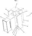
- the in FIG. 1 shown device body 100 of a refrigerator and / or freezer according to the invention comprises a frame substructure 110 made of metal, which forms a base portion 111 at the bottom, the bottom of a bottom plate 112th and bounded above by a base cover plate 113.
- the frame substructure 110 further includes a framework section that extends to the upper end of the device body 100.
- the framework section includes vertical beams 115 extending along the back of the device body 100 and a rectangular ceiling frame 116.
- a box-shaped vacuum insulation body 120 is used, which surrounds the interior of the finished device substantially completely. It has a barrier film and a support material arranged in the core enclosed by the barrier film. A likewise box-shaped inner container 130, which is produced by deep-drawing a plastic sheet, is inserted into the space defined by the box-shaped vacuum insulation body 120.
- the side, rear and upper outer surfaces of the device body 100 are boarded with wall plates, all of which are sheet metal plates. Namely, the top of the device body 100 is covered with a ceiling wall plate 140, the back of the device body 100 with a back wall plate 150, and the both sides of the device body 100 with side wall plates 160.
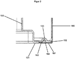
- FIG. 2 It can be seen that the side wall panels 160 are latched directly to the inner container 130 at the front of the device.
- the inner container 130 has at its front end as a conclusion a circumferential profile with a lying in the opening plane of the interior coupling surface 131.
- the profile covers and protects the vacuum insulation body 120 on the front of the device.
- the distal end portion 132 of the coupling surface is slightly stepped back. In this reclassified end portion 132, a groove 133 is incorporated at least in the lateral sections.
- the leading edge of the respective side wall panel 160 is crimped inwardly to a front standing seam 161.
- the front standing seam 161 overlaps the coupling surface 131 of the inner container 130 in the recessed distal end portion 132 such that the end surfaces of the front standing seam 161 and the non-recessed portion of the coupling surface 131 are flush with each other.
- the inwardly directed edge of the front standing seam is itself crimped back to a front envelope 162.
- a continuous web 163 is bent backwards, which engages in the groove 133 of the inner container 130.
- the groove 133 and the web 163 together form a latching connection between inner container 130 and side wall plate 160.
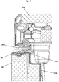
- FIG. 3 can recognize, at the flush transition of the end faces of the front standing seam 161 and the non-recessed portion of the coupling surface 131 in the finished device disposed on the appliance door 200 seal 201 rest.
- the trailing edge of the respective side wall panel 160 is also crimped inwardly toward a rear standing seam 164.
- the rear standing seam 164 overlaps the side edge area of the back wall panel 150.
- the inwardly directed edge of the rear standing seam 164 is crimped forward to a rear envelope 165.
- the lateral edge region of the rear wall panel 150 has a rearwardly projecting cutout 151, behind which the edge of the rear envelope 165 engages.
- the side wall panels 160 are flanged to form standing seams which engage over the top wall panel 140 and the bottom panel 112, respectively.
Landscapes
- Engineering & Computer Science (AREA)
- Chemical & Material Sciences (AREA)
- Combustion & Propulsion (AREA)
- Physics & Mathematics (AREA)
- Mechanical Engineering (AREA)
- Thermal Sciences (AREA)
- General Engineering & Computer Science (AREA)
- Refrigerator Housings (AREA)
- Devices That Are Associated With Refrigeration Equipment (AREA)
Abstract
Description
- Die Erfindung betrifft ein Kühl- und/oder Gefriergerät mit einem Gerätekorpus, der einen Innenraum definiert und der eine Wärmedämmung, einen Innenbehälter und eine äußere Verschalung aufweist. Die Erfindung betrifft ferner ein Verfahren zur Herstellung eines derartigen Kühl- und/oder Gefriergerätes.
- Es ist bekannt, einen Gerätekorpus unter Verwendung einer Rahmenunterkonstruktion, einer Wärmedämmung, eines Innenbehälters und einer äußere Verschalung zusammenzusetzen. Ferner ist bekannt, zur Wärmedämmung eines Kühl- und/oder Gefriergerätes einen oder mehrere Vakuumisolationskörper zu verwenden, da diese besonders vorteilhafte Dämmeigenschaften aufweisen. Auch Vollvakuumdämmungen, bei welchen der Innenraum vollständig vakuumisoliert ist, sind bekannt. Mitunter ist der Zusammenbau des Gerätekorpus aber aufwändig. Dieses Problem verstärkt sich bei Verwendung einer Vakuumisolation und insbesondere einer Vollvakuumdämmung. Hier muss auch darauf geachtet werden, dass die Isolationskörper gegen Beschädigungen geschützt werden.
- Aufgabe der Erfindung ist es, ein Kühl- und/oder Gefriergerät bereitzustellen, welches selbst im Falle einer Vakuumisolation einfach und kostengünstig herzustellen und zu warten ist.
- Vor diesem Hintergrund betrifft die Erfindung ein Kühl- und/oder Gefriergerät mit einem Gerätekorpus, der einen Innenraum definiert und der eine Wärmedämmung, einen Innenbehälter und eine äußere Verschalung aufweist, wobei die Verschalung eine Seitenwandplatte aufweist, deren Vorderkante nach innen zu einem vorderen Stehfalz umgebördelt ist, und wobei der vordere Stehfalz die Stirnseite des Innenbehälters zumindest teilweise übergreift und mit dieser verrastet ist.
- Hierdurch wird einerseits die Wärmedämmung effektiv geschützt. Ferner werden keine oder lediglich eine schwache Wärmebrücke ausgebildet und der Zusammenbau der einzelnen Komponenten maßgeblich vereinfacht.
- Vorzugsweise weist das Gerät ferner eine Rahmenunterkonstruktion auf. Es kann vorgesehen sein, dass die Außenseite der Rahmenunterkonstruktion zumindest seitlich, oben und hinten im Wesentlichen vollflächig mit Wandplatten verschalt ist. Vorzugsweise weist die Verschalung zwei Seitenwandplatten an der linken und rechten Seite des Gerätekorpus auf, die entsprechend ausgebildet sind. Alle nachfolgenden Ausführungen gelten in einer Ausführungsform für die rechte und für die linke Seite des Gerätekorpus entsprechend.
- Die Verrastung zwischen dem vorderen Stehfalz der Seitenwandplatte und der Stirnseite des Innenbehälters erfolgt vorzugsweise direkt, d.h., ohne ein zwischengelagertes Verbindungsteil.
- Bei dem Innenbehälter handelt es sich vorzugsweise um ein tiefgezogenes Kunststoffteil. Bei den Seitenwandplatten handelt es sich vorzugsweise um Bleche. Auch bei der Rückwandplatte und/oder der Deckenplatte kann es sich um Bleche handeln.
- In einer Ausführungsform ist vorgesehen, dass die Wärmedämmung einen einteiligen, kistenförmigen Vakuumisolationskörper umfasst, der den Innenraum im Wesentlichen vollständig umgibt. In dieser Ausführungsform weist der Gerätekorpus eine Vollvakuumdämmung auf.
- Vorzugsweise weist der Vakuumisolationskörper eine Barrierefolie und ein im von der Barrierefolie eingeschlossenen Kern angeordnetes Stützmaterial auf. Er kann insgesamt in die Rahmenkonstruktion eingesetzt werden. Der Innenbehälter kann in den vom kistenförmigen Vakuumisolationskörper definierten Raum eingesetzt werden. Die durch die Wandplatten gebildete Verschalung schützt den Vakuumisolationskörper von außen.
- Weiterhin kann vorgesehen sein, dass am vorderen Stehfalz eine Rastnase ausgebildet ist, die in eine Rastvertiefung an der Stirnseite des Innenbehälters eingreift. Die Rastnase und die Rastvertiefung können sich durchgehend über die gesamte Höhe des jeweiligen Bauteils erstrecken, die Rastnase also über die gesamte Höhe der Seitenwandplatte und die Rastvertiefung über die gesamte Höhe des Innenbehälters.
- In einer Ausführungsform ist vorgesehen, dass es sich bei der Rastvertiefung um eine vertikal entlang der Stirnseite des Innenbehälters verlaufende Nut handelt. Die Nut kann in einen Kunststoffinnenbehälter auf einfache Art eingeformt werden.
- In einer Ausführungsform ist vorgesehen, dass die nach innen gerichtete Kante des vorderen Stehfalzes ihrerseits nach hinten zu einem vorderen Umschlag umgebördelt ist und es sich bei der Rastnase um einen vertikal verlaufenden Steg handelt, der aus dem vorderen Umschlag gebogen ist. Zur Herstellung der Rastnase ist in dieser Ausführungsform lediglich eine Biegung der Seitenwandplatte erforderlich. Es ist keine Stanzung und keine Anbringung zusätzlicher Teile notwendig.
- In einer weiteren Ausführungsform ist vorgesehen, dass das Gerät ferner eine Gerätetüre mit einer umlaufenden Dichtung aufweist, wobei die Dichtung bei geschlossener Gerätetüre im Übergangsbereich zwischen vorderem Stehfalz und Stirnseite des Innenbehälters aufliegt. Durch das Aufliegen der Dichtung im Übergangsbereich zwischen vorderem Stehfalz der Seitenwandplatte und Stirnseite des Innenbehälters, mithin also zwischen Innenbehälter und Verschalung, kann die Tendenz zur Bildung von Wärmebrücken weiter minimiert werden.
- Die Verschalung kann ferner eine Rückwandplatte aufweisen, wobei auch die Hinterkante der Seitenwandplatte nach innen zu einem hinteren Stehfalz umgebördelt ist, wobei der hintere Stehfalz den seitlichen Randbereich der Rückwandplatte übergreift und mit diesem verrastet ist. Es kann also vorgesehen sein, dass die Seitenwandplatte sowohl die Stirnseite des Innenbehälters als auch die Rückwandplatte übergreift, sodass bei seitlicher Betrachtung keine Übergänge zwischen den einzelnen Wänden des Gerätekorpus sichtbar sind.
- In einer Ausführungsform ist vorgesehen, dass die nach innen gerichtete Kante des hinteren Stehfalzes ihrerseits nach vorne zu einem hinteren Umschlag umgebördelt ist und dass der seitliche Randbereich der Rückwandplatte ein nach hinten abstehendes Stoppelement aufweist, das die Kante des hinteren Umschlags hält. Das Stoppelement kann sich aus mehreren diskreten Elementen zusammensetzen oder durchgehend sein. Beispielsweise kann es sich um Ausformungen oder Ausstanzungen handeln.
- Die Verschalung kann ferner eine Deckenplatte aufweisen, wobei auch die Oberkante der Seitenwandplatte nach innen zu einem oberen Stehfalz umgebördelt ist, wobei der obere Stehfalz den seitlichen Randbereich der Deckenplatte übergreift. Die Deckenplatte kann ebenfalls formschlüssig mit der Seitenplatte verbunden sein.
- Es kann also vorgesehen sein, dass die Seitenwandplatte sowohl die Stirnseite des Innenbehälters als auch die Rückwandplatte und die Deckenplatte übergreift. Dies erlaubt es, die Seitenwandplatte erst am Ende der Fertigung des Gerätekorpus auf die weiteren Bauteile des Gerätekorpus, d.h., die Rahmenunterkonstruktion, die Wärmedämmung, den Innenbehälter und die weiteren Verschalungsplatten aufzusetzen, vorzugsweise aufzustecken, und so die Fertigung des Gerätekorpus zu finalisieren. Dies führt zu einer einfachen und kostengünstigen Fertigung.
- Unterhalb des Innenraums kann durch die Rahmenunterkonstruktion ein Sockelbereich definiert werden, welcher der Aufnahme von Komponenten des Kältemittelkreislaufs dient.
- In einer Ausführungsform ist vorgesehen, dass auch die Unterkante der Seitenwandplatte nach innen zu einem unteren Stehfalz umgebördelt ist, wobei der untere Stehfalz den seitlichen Randbereich der Unterseite der Rahmenunterkonstruktion bzw. des Sockelbereichs übergreift.
- In einer Ausführungsform ist vorgesehen, dass alle Komponenten des Kältemittelkreislaufs, also Kompressor, Verflüssiger, Drossel und Verdampfer gemeinsam auf einem Aggregatträger verbaut sind, das insgesamt vom Gerätekorpus getrennt und aus dem Gerät entnommen werden kann. Es kann vorgesehen sein, dass auch weitere Komponenten wie ein Maschinenraumventilator, ein Kühlraumventilator, eine Steuereinheit, eine Tauwasserschale und ein Netzteil mit Verkabelung auf dem Aggregatträger verbaut sind. Es kann vorgesehen sein, dass dieser Aggregatträger zwei Abschnitte aufweist, wobei ein Abschnitt im Sockel des Gerätekorpus und der andere Abschnitt im untersten Bereich des Innenraums aufgenommen sind.
- Vor dem eingangs genannten Hintergrund betrifft die Erfindung ferner ein Verfahren zur Herstellung eines erfindungsgemäßen Kühl- und/oder Gefriergeräts, wobei bei der Herstellung des Gerätekorpus der Innenbehälter, die Wärmedämmung, gegebenenfalls die Rahmenunterkonstruktion sowie Teile der Verschalung miteinander verbunden werden und sodann die Seitenwandplatten aufgesetzt werden.
- Die Seitenwandplatten werden also abschließend aufgesetzt, wenn die verbleibenden der genannten Teile des Gerätekorpus bereits zusammengesetzt wurden. Vorzugsweise werden die Seitenwandplatten mit den verbleibenden Teilen des Gerätekorpus formschlüssig verbunden, vorzugsweise verrastet.
- Nach Fertigstellung des Gerätekorpus wird vorzugsweise ein Aggregatträger mit den Komponenten des Kältemittelkreislaufs als Ganzes in den Gerätekorpus eingesetzt.
- An dieser Stelle wird darauf hingewiesen, dass die Begriffe "ein" und "eine" nicht zwingend auf genau eines der Elemente verweisen, wenngleich dies eine mögliche Ausführung darstellt, sondern auch eine Mehrzahl der Elemente bezeichnen können. Ebenso schließt die Verwendung des Plurals auch das Vorhandensein des fraglichen Elementes in der Einzahl ein und umgekehrt umfasst der Singular auch mehrere der fraglichen Elemente.
- Weitere Einzelheiten und Vorteile der Erfindung ergeben sich aus dem nachfolgend anhand der Figuren dargestellten Ausführungsbeispiel. In den Figuren zeigen:
- Figur 1:
- seitliche Explosionsdarstellung eines Gerätekorpus eines erfindungsgemäßen Kühl- und/oder Gefriergerätes;
- Figur 2:
- einen horizontalen Schnitt im Bereich der vorderen Seitenkante des Gerätekorpus;
- Figur 3:
- einen horizontalen Schnitt im Bereich der vorderen Seitenkante des Gerätekorpus mit aufgesetzter Gerätetüre; und
- Figur 4:
- einen horizontalen Schnitt im Bereich der hinteren Seitenkante des Gerätekorpus.
- Der in
Figur 1 gezeigte Gerätekorpus 100 eines erfindungsgemäßen Kühl- und/oder Gefriergerätes umfasst eine Rahmenunterkonstruktion 110 aus Metall, die am unteren Ende einen Sockelbereich 111 ausbildet, der unten von einer Bodenplatte 112 und oben von einer Sockeldeckplatte 113 begrenzt wird. Die Rahmenunterkonstruktion 110 umfasst ferner einen Gerüstabschnitt, der bis zum oberen Ende des Gerätekorpus 100 reicht. Der Gerüstabschnitt umfasst vertikale Träger 115, die entlang der Rückseite des Gerätekorpus 100 verlaufen, und ein rechteckiges Deckengerüst 116. - Im zwischen der Sockeldeckplatte 113 und dem Deckengerüst 116 gebildeten Raum ist ein kistenförmiger Vakuumisolationskörper 120 eingesetzt, der den Innenraum des fertigen Gerätes im Wesentlichen vollständig umgibt. Er weist eine Barrierefolie und ein im von der Barrierefolie eingeschlossenen Kern angeordnetes Stützmaterial auf. Ein ebenfalls kistenförmiger Innenbehälter 130, der durch Tiefziehen eines Kunststoffblechs hergestellt wird, ist passgenau in den vom kistenförmigen Vakuumisolationskörper 120 definierten Raum eingesetzt.
- Die seitlichen, hinteren und oberen Außenflächen des Gerätekorpus 100 sind mit Wandplatten verschalt, bei denen es sich allesamt um Metallblechplatten handelt. Nämlich sind die Oberseite des Gerätekorpus 100 mit einer Deckenwandplatte 140, die Rückseite des Gerätekorpus 100 mit einer Rückwandplatte 150 und die beiden Seiten des Gerätekorpus 100 mit Seitenwandplatten 160 verschalt.
- In
Figur 2 wird ersichtlich, dass die Seitenwandplatten 160 an der Vorderseite des Geräts direkt mit dem Innenbehälter 130 verrastet sind. - Der Innenbehälter 130 weist an seiner vorderen Stirnseite als Abschluss ein umlaufendes Profil mit einer in der Öffnungsebene des Innenraums liegenden Kopplungsfläche 131 auf. Das Profil überdeckt und schützt den Vakuumisolationskörper 120 an der Gerätestirnseite. Der distale Endbereich 132 der Kopplungsfläche ist leicht nach hinten zurückgestuft. In diesen zurückgestuften Endbereich 132 ist zumindest in den seitlichen Abschnitten eine Nut 133 eingearbeitet.
- Die Vorderkante der jeweiligen Seitenwandplatte 160 ist nach innen zu einem vorderen Stehfalz 161 umgebördelt. Der vordere Stehfalz 161 übergreift die Kopplungsfläche 131 des Innenbehälters 130 im zurückversetzten distalen Endbereich 132 derart, dass die Stirnflächen des vorderen Stehfalzes 161 und des nicht zurückversetzten Teils der Kopplungsfläche 131 bündig ineinander übergehen. Die nach innen gerichtete Kante des vorderen Stehfalzes ist ihrerseits nach hinten zu einem vorderen Umschlag 162 umgebördelt. Innerhalb des vorderen Umschlags 162 ist ein durchlaufender Steg 163 nach hinten ausgebogen, der in die Nut 133 des Innenbehälters 130 einrastet. Die Nut 133 und der Steg 163 bilden gemeinsam eine Rastverbindung zwischen Innenbehälter 130 und Seitenwandplatte 160 aus.
- Wie sich dies aus
Figur 3 erkennen lässt, kann am bündigen Übergang der Stirnflächen des vorderen Stehfalzes 161 und des nicht zurückversetzten Teils der Kopplungsfläche 131 im fertigen Gerät eine an der Gerätetür 200 angeordnete Dichtung 201 aufliegen. - In
Figur 4 wird ersichtlich, dass die Seitenwandplatten 160 an der Rückseite des Geräts direkt und formschlüssig mit der Rückwandplatte 150 verbunden sind. - Nämlich ist auch die Hinterkante der jeweiligen Seitenwandplatte 160 nach innen zu einem hinteren Stehfalz 164 umgebördelt. Der hintere Stehfalz 164 übergreift den seitlichen Randbereich der Rückwandplatte 150. Die nach innen gerichtete Kante des hinteren Stehfalzes 164 ist nach vorne zu einem hinteren Umschlag 165 umgebördelt. Der seitliche Randbereich der Rückwandplatte 150 weist eine nach hinten abstehende Ausstanzung 151 auf, hinter der die Kante des hinteren Umschlags 165 einrastet.
- Auch an der Oberkante und an der Unterkante sind die Seitenwandplatten 160 umgebördelt, um Stehfalze auszubilden, welche die Deckenwandplatte 140 bzw. die Bodenplatte 112 übergreifen.
Claims (10)
- Kühl- und/oder Gefriergerät mit einem Gerätekorpus, der einen Innenraum definiert und der eine Wärmedämmung, einen Innenbehälter und eine äußere Verschalung aufweist,
dadurch gekennzeichnet,
dass die Verschalung eine Seitenwandplatte aufweist, deren Vorderkante nach innen zu einem vorderen Stehfalz umgebördelt ist, wobei der vordere Stehfalz die Stirnseite des Innenbehälters zumindest teilweise übergreift und mit dieser verrastet ist. - Kühl- und/oder Gefriergerät nach Anspruch 1, dadurch gekennzeichnet, dass die Wärmedämmung einen einteiligen, kistenförmigen Vakuumisolationskörper umfasst, der den Innenraum im Wesentlichen vollständig umgibt.
- Kühl- und/oder Gefriergerät nach einem der vorhergehenden Ansprüche, dadurch gekennzeichnet, dass am vorderen Stehfalz eine Rastnase ausgebildet ist, die in eine Rastvertiefung an der Stirnseite des Innenbehälters eingreift.
- Kühl- und/oder Gefriergerät nach Anspruch 3, dadurch gekennzeichnet, dass es sich bei der Rastvertiefung um eine vertikal entlang der Stirnseite des Innenbehälters verlaufende Nut handelt.
- Kühl- und/oder Gefriergerät nach Anspruch 3 oder 4, dadurch gekennzeichnet, dass die nach innen gerichtete Kante des vorderen Stehfalzes ihrerseits nach hinten zu einem vorderen Umschlag umgebördelt ist und es sich bei der Rastnase um einen vertikal verlaufenden Steg handelt, der aus dem vorderen Umschlag gebogen ist.
- Kühl- und/oder Gefriergerät nach einem der vorhergehenden Ansprüche, dadurch gekennzeichnet, dass das Gerät ferner eine Gerätetüre mit einer umlaufenden Dichtung aufweist, wobei die Dichtung bei geschlossener Gerätetüre im Übergangsbereich zwischen vorderem Stehfalz und Stirnseite des Innenbehälters aufliegt.
- Kühl- und/oder Gefriergerät nach einem der vorhergehenden Ansprüche, dadurch gekennzeichnet, dass die Verschalung ferner eine Rückwandplatte aufweist und dass auch die Hinterkante der Seitenwandplatte nach innen zu einem hinteren Stehfalz umgebördelt ist, wobei der hintere Stehfalz den seitlichen Randbereich der Rückwandplatte übergreift und mit diesem verrastet ist.
- Kühl- und/oder Gefriergerät nach Anspruch 6, dadurch gekennzeichnet, dass die nach innen gerichtete Kante des hinteren Stehfalzes ihrerseits nach vorne zu einem hinteren Umschlag umgebördelt ist und dass der seitliche Randbereich der Rückwandplatte ein nach hinten abstehendes Stoppelement aufweist, das die Kante des hinteren Umschlags hält.
- Kühl- und/oder Gefriergerät nach einem der vorhergehenden Ansprüche, dadurch gekennzeichnet, dass die Verschalung ferner eine Deckenplatte aufweist und dass auch die Oberkante der Seitenwandplatte nach innen zu einem oberen Stehfalz umgebördelt ist, wobei der obere Stehfalz den seitlichen Randbereich der Deckenplatte übergreift.
- Verfahren zur Herstellung eines Kühl- und/oder Gefriergeräts nach einem der vorhergehenden Ansprüche,
dadurch gekennzeichnet,
dass bei der Herstellung des Gerätekorpus der Innenbehälter, die Wärmedämmung, sowie Teile der Verschalung miteinander verbunden werden und sodann die Seitenwandplatten aufgesetzt werden.
Applications Claiming Priority (1)
| Application Number | Priority Date | Filing Date | Title |
|---|---|---|---|
| DE102017119046.5A DE102017119046A1 (de) | 2017-08-21 | 2017-08-21 | Kühl- und/oder Gefriergerät |
Publications (2)
| Publication Number | Publication Date |
|---|---|
| EP3447416A1 true EP3447416A1 (de) | 2019-02-27 |
| EP3447416B1 EP3447416B1 (de) | 2022-04-13 |
Family
ID=63350368
Family Applications (1)
| Application Number | Title | Priority Date | Filing Date |
|---|---|---|---|
| EP18189861.0A Not-in-force EP3447416B1 (de) | 2017-08-21 | 2018-08-21 | Kühl- und/oder gefriergerät und verfahren zur herstellung davon |
Country Status (3)
| Country | Link |
|---|---|
| EP (1) | EP3447416B1 (de) |
| DE (1) | DE102017119046A1 (de) |
| ES (1) | ES2920529T3 (de) |
Cited By (2)
| Publication number | Priority date | Publication date | Assignee | Title |
|---|---|---|---|---|
| EP4202325A1 (de) * | 2021-12-21 | 2023-06-28 | Liebherr-Hausgeräte Ochsenhausen GmbH | Kühl- und/oder gefriergerät |
| WO2023181433A1 (ja) * | 2022-03-23 | 2023-09-28 | 日立グローバルライフソリューションズ株式会社 | 貯蔵庫 |
Citations (13)
| Publication number | Priority date | Publication date | Assignee | Title |
|---|---|---|---|---|
| JPS5598976U (de) * | 1978-12-28 | 1980-07-09 | ||
| US4301663A (en) * | 1978-12-28 | 1981-11-24 | The General Corporation | Refrigerating cabinet |
| JPS588093U (ja) * | 1981-07-08 | 1983-01-19 | 三菱電機株式会社 | 冷蔵庫用断熱箱 |
| JPS58179491U (ja) * | 1982-05-26 | 1983-12-01 | 株式会社日立製作所 | 冷蔵庫の断熱箱体 |
| JPS58192388U (ja) * | 1982-06-18 | 1983-12-21 | 株式会社日立製作所 | 冷蔵庫の断熱箱体 |
| DE19756858A1 (de) * | 1997-12-19 | 1999-06-24 | Bosch Siemens Hausgeraete | Kältegerät |
| JP2000227274A (ja) * | 1998-11-18 | 2000-08-15 | Hoshizaki Electric Co Ltd | 回転成形部品を用いた構造体およびその組立て方法 |
| US20020014818A1 (en) * | 1998-01-27 | 2002-02-07 | Mitsubishi Denki Kabushiki Kaisha | Full vacuum heat insulation box body and method for producing and disassembling the same |
| WO2012028998A2 (de) * | 2010-08-31 | 2012-03-08 | BSH Bosch und Siemens Hausgeräte GmbH | Kühlgerät |
| US20120297813A1 (en) * | 2011-05-26 | 2012-11-29 | Kenneth Joseph Hanley | Method and apparatus for insulating a refrigeration appliance |
| US20130256304A1 (en) * | 2012-04-02 | 2013-10-03 | Jeffrey Lynn Jessie | Refrigerator cabinet assembly |
| WO2014155398A1 (en) * | 2013-03-27 | 2014-10-02 | Industrie Scaffalature Arredamenti Isa S.R.L. | Chiller counter and method for assembling the counter |
| DE102014109332A1 (de) * | 2014-07-03 | 2016-01-07 | Jobst H. KERSPE | Isoliergehäuse und Verfahren zur Herstellung eines Isoliergehäuses |
Family Cites Families (3)
| Publication number | Priority date | Publication date | Assignee | Title |
|---|---|---|---|---|
| DE102011006238A1 (de) * | 2011-03-28 | 2012-10-04 | BSH Bosch und Siemens Hausgeräte GmbH | Modularer Gerätekorpus |
| JP5736992B2 (ja) * | 2011-06-15 | 2015-06-17 | 三菱電機株式会社 | 冷蔵庫 |
| DE102012223544A1 (de) * | 2012-12-18 | 2014-06-18 | BSH Bosch und Siemens Hausgeräte GmbH | Wandungsanordnung für ein Haushaltskältegerät sowie Haushaltskältegerät |
-
2017
- 2017-08-21 DE DE102017119046.5A patent/DE102017119046A1/de not_active Withdrawn
-
2018
- 2018-08-21 EP EP18189861.0A patent/EP3447416B1/de not_active Not-in-force
- 2018-08-21 ES ES18189861T patent/ES2920529T3/es active Active
Patent Citations (13)
| Publication number | Priority date | Publication date | Assignee | Title |
|---|---|---|---|---|
| US4301663A (en) * | 1978-12-28 | 1981-11-24 | The General Corporation | Refrigerating cabinet |
| JPS5598976U (de) * | 1978-12-28 | 1980-07-09 | ||
| JPS588093U (ja) * | 1981-07-08 | 1983-01-19 | 三菱電機株式会社 | 冷蔵庫用断熱箱 |
| JPS58179491U (ja) * | 1982-05-26 | 1983-12-01 | 株式会社日立製作所 | 冷蔵庫の断熱箱体 |
| JPS58192388U (ja) * | 1982-06-18 | 1983-12-21 | 株式会社日立製作所 | 冷蔵庫の断熱箱体 |
| DE19756858A1 (de) * | 1997-12-19 | 1999-06-24 | Bosch Siemens Hausgeraete | Kältegerät |
| US20020014818A1 (en) * | 1998-01-27 | 2002-02-07 | Mitsubishi Denki Kabushiki Kaisha | Full vacuum heat insulation box body and method for producing and disassembling the same |
| JP2000227274A (ja) * | 1998-11-18 | 2000-08-15 | Hoshizaki Electric Co Ltd | 回転成形部品を用いた構造体およびその組立て方法 |
| WO2012028998A2 (de) * | 2010-08-31 | 2012-03-08 | BSH Bosch und Siemens Hausgeräte GmbH | Kühlgerät |
| US20120297813A1 (en) * | 2011-05-26 | 2012-11-29 | Kenneth Joseph Hanley | Method and apparatus for insulating a refrigeration appliance |
| US20130256304A1 (en) * | 2012-04-02 | 2013-10-03 | Jeffrey Lynn Jessie | Refrigerator cabinet assembly |
| WO2014155398A1 (en) * | 2013-03-27 | 2014-10-02 | Industrie Scaffalature Arredamenti Isa S.R.L. | Chiller counter and method for assembling the counter |
| DE102014109332A1 (de) * | 2014-07-03 | 2016-01-07 | Jobst H. KERSPE | Isoliergehäuse und Verfahren zur Herstellung eines Isoliergehäuses |
Cited By (2)
| Publication number | Priority date | Publication date | Assignee | Title |
|---|---|---|---|---|
| EP4202325A1 (de) * | 2021-12-21 | 2023-06-28 | Liebherr-Hausgeräte Ochsenhausen GmbH | Kühl- und/oder gefriergerät |
| WO2023181433A1 (ja) * | 2022-03-23 | 2023-09-28 | 日立グローバルライフソリューションズ株式会社 | 貯蔵庫 |
Also Published As
| Publication number | Publication date |
|---|---|
| DE102017119046A1 (de) | 2019-02-21 |
| EP3447416B1 (de) | 2022-04-13 |
| ES2920529T3 (es) | 2022-08-05 |
Similar Documents
| Publication | Publication Date | Title |
|---|---|---|
| WO2017092727A1 (de) | Rahmengestell für eine schaltschrankanordnung | |
| EP2059748B1 (de) | Einbau-kältegerät mit ausgabevorrichtung | |
| WO2007122072A2 (de) | Mehrteiliges haushaltsgerät | |
| DE202009007424U1 (de) | Außenmaterial-Befestigungselement | |
| DE202012008857U1 (de) | Vorwandmontagesystem | |
| EP3447416B1 (de) | Kühl- und/oder gefriergerät und verfahren zur herstellung davon | |
| EP2725159A1 (de) | Haltevorrichtung, Verfahren zum Herstellen einer Haltevorrichtung sowie Verwendung einer Haltevorrichtung an einer Vorhangwand | |
| DE202005000909U1 (de) | Kühl- und Gefriergerät | |
| DE102010063448A1 (de) | Geschirrspülmaschine | |
| EP2490576B1 (de) | Temperiervorrichtung umfassend einen gehäuserahmen | |
| EP1481209B1 (de) | Randabschlussteil für eine glasplatte | |
| EP2756244A1 (de) | Kältegerät, insbesondere haushaltskältegerät | |
| DE102020202883A1 (de) | Unterbaustruktur für ein Fahrzeug | |
| DE102010002043A1 (de) | Elektrisches Gerät | |
| DE102019218222A1 (de) | Haushaltskühlgerät mit einem Vorsprung als Kondenswasser-Tropfleiste in einer Wand eines Eisbereiters | |
| EP2311347A1 (de) | Verschlusselement zum Verschließen eines Spaltes zwischen Einbaugerät und Möbelumbau | |
| DE202007008901U1 (de) | Profilverbinder und Verkleidung | |
| EP4015931A1 (de) | Wanddurchführungseinheit für den anschluss eines haustechnikgeräts | |
| EP3257413B1 (de) | Dekor- und/oder funktionsteil für den einbau in einen eckbereich oder eine nische, beispielsweise eines zumindest teilweise gefliesten raumes | |
| DE10208061A1 (de) | Kältegerätetür und damit ausgestattetes Kältegerät | |
| DE102008042944B4 (de) | Geschirrspülmaschine mit einem Frontelement | |
| EP2667128A2 (de) | Kältegerät, insbesondere Haushaltskältegerät | |
| DE202014100557U1 (de) | Möbelauszug und Frontblende für einen Möbelauszug | |
| WO2020002452A1 (de) | Kühl- und/oder gefriergerät mit feuerfeste trennschicht | |
| EP1898169A2 (de) | Frontplatte für ein Haushaltsgerät |
Legal Events
| Date | Code | Title | Description |
|---|---|---|---|
| PUAI | Public reference made under article 153(3) epc to a published international application that has entered the european phase |
Free format text: ORIGINAL CODE: 0009012 |
|
| STAA | Information on the status of an ep patent application or granted ep patent |
Free format text: STATUS: THE APPLICATION HAS BEEN PUBLISHED |
|
| AK | Designated contracting states |
Kind code of ref document: A1 Designated state(s): AL AT BE BG CH CY CZ DE DK EE ES FI FR GB GR HR HU IE IS IT LI LT LU LV MC MK MT NL NO PL PT RO RS SE SI SK SM TR |
|
| AX | Request for extension of the european patent |
Extension state: BA ME |
|
| STAA | Information on the status of an ep patent application or granted ep patent |
Free format text: STATUS: REQUEST FOR EXAMINATION WAS MADE |
|
| 17P | Request for examination filed |
Effective date: 20190820 |
|
| STAA | Information on the status of an ep patent application or granted ep patent |
Free format text: STATUS: EXAMINATION IS IN PROGRESS |
|
| 17Q | First examination report despatched |
Effective date: 20191202 |
|
| GRAP | Despatch of communication of intention to grant a patent |
Free format text: ORIGINAL CODE: EPIDOSNIGR1 |
|
| STAA | Information on the status of an ep patent application or granted ep patent |
Free format text: STATUS: GRANT OF PATENT IS INTENDED |
|
| INTG | Intention to grant announced |
Effective date: 20211108 |
|
| GRAS | Grant fee paid |
Free format text: ORIGINAL CODE: EPIDOSNIGR3 |
|
| GRAA | (expected) grant |
Free format text: ORIGINAL CODE: 0009210 |
|
| STAA | Information on the status of an ep patent application or granted ep patent |
Free format text: STATUS: THE PATENT HAS BEEN GRANTED |
|
| AK | Designated contracting states |
Kind code of ref document: B1 Designated state(s): AL AT BE BG CH CY CZ DE DK EE ES FI FR GB GR HR HU IE IS IT LI LT LU LV MC MK MT NL NO PL PT RO RS SE SI SK SM TR |
|
| REG | Reference to a national code |
Ref country code: GB Ref legal event code: FG4D Free format text: NOT ENGLISH |
|
| REG | Reference to a national code |
Ref country code: CH Ref legal event code: EP |
|
| REG | Reference to a national code |
Ref country code: DE Ref legal event code: R096 Ref document number: 502018009376 Country of ref document: DE |
|
| REG | Reference to a national code |
Ref country code: IE Ref legal event code: FG4D Free format text: LANGUAGE OF EP DOCUMENT: GERMAN |
|
| REG | Reference to a national code |
Ref country code: AT Ref legal event code: REF Ref document number: 1483701 Country of ref document: AT Kind code of ref document: T Effective date: 20220515 |
|
| REG | Reference to a national code |
Ref country code: ES Ref legal event code: FG2A Ref document number: 2920529 Country of ref document: ES Kind code of ref document: T3 Effective date: 20220805 |
|
| REG | Reference to a national code |
Ref country code: LT Ref legal event code: MG9D |
|
| REG | Reference to a national code |
Ref country code: NL Ref legal event code: MP Effective date: 20220413 |
|
| PG25 | Lapsed in a contracting state [announced via postgrant information from national office to epo] |
Ref country code: NL Free format text: LAPSE BECAUSE OF FAILURE TO SUBMIT A TRANSLATION OF THE DESCRIPTION OR TO PAY THE FEE WITHIN THE PRESCRIBED TIME-LIMIT Effective date: 20220413 |
|
| PG25 | Lapsed in a contracting state [announced via postgrant information from national office to epo] |
Ref country code: SE Free format text: LAPSE BECAUSE OF FAILURE TO SUBMIT A TRANSLATION OF THE DESCRIPTION OR TO PAY THE FEE WITHIN THE PRESCRIBED TIME-LIMIT Effective date: 20220413 Ref country code: PT Free format text: LAPSE BECAUSE OF FAILURE TO SUBMIT A TRANSLATION OF THE DESCRIPTION OR TO PAY THE FEE WITHIN THE PRESCRIBED TIME-LIMIT Effective date: 20220816 Ref country code: NO Free format text: LAPSE BECAUSE OF FAILURE TO SUBMIT A TRANSLATION OF THE DESCRIPTION OR TO PAY THE FEE WITHIN THE PRESCRIBED TIME-LIMIT Effective date: 20220713 Ref country code: LT Free format text: LAPSE BECAUSE OF FAILURE TO SUBMIT A TRANSLATION OF THE DESCRIPTION OR TO PAY THE FEE WITHIN THE PRESCRIBED TIME-LIMIT Effective date: 20220413 Ref country code: HR Free format text: LAPSE BECAUSE OF FAILURE TO SUBMIT A TRANSLATION OF THE DESCRIPTION OR TO PAY THE FEE WITHIN THE PRESCRIBED TIME-LIMIT Effective date: 20220413 Ref country code: GR Free format text: LAPSE BECAUSE OF FAILURE TO SUBMIT A TRANSLATION OF THE DESCRIPTION OR TO PAY THE FEE WITHIN THE PRESCRIBED TIME-LIMIT Effective date: 20220714 Ref country code: FI Free format text: LAPSE BECAUSE OF FAILURE TO SUBMIT A TRANSLATION OF THE DESCRIPTION OR TO PAY THE FEE WITHIN THE PRESCRIBED TIME-LIMIT Effective date: 20220413 Ref country code: BG Free format text: LAPSE BECAUSE OF FAILURE TO SUBMIT A TRANSLATION OF THE DESCRIPTION OR TO PAY THE FEE WITHIN THE PRESCRIBED TIME-LIMIT Effective date: 20220713 |
|
| PG25 | Lapsed in a contracting state [announced via postgrant information from national office to epo] |
Ref country code: RS Free format text: LAPSE BECAUSE OF FAILURE TO SUBMIT A TRANSLATION OF THE DESCRIPTION OR TO PAY THE FEE WITHIN THE PRESCRIBED TIME-LIMIT Effective date: 20220413 Ref country code: PL Free format text: LAPSE BECAUSE OF FAILURE TO SUBMIT A TRANSLATION OF THE DESCRIPTION OR TO PAY THE FEE WITHIN THE PRESCRIBED TIME-LIMIT Effective date: 20220413 Ref country code: LV Free format text: LAPSE BECAUSE OF FAILURE TO SUBMIT A TRANSLATION OF THE DESCRIPTION OR TO PAY THE FEE WITHIN THE PRESCRIBED TIME-LIMIT Effective date: 20220413 Ref country code: IS Free format text: LAPSE BECAUSE OF FAILURE TO SUBMIT A TRANSLATION OF THE DESCRIPTION OR TO PAY THE FEE WITHIN THE PRESCRIBED TIME-LIMIT Effective date: 20220813 |
|
| REG | Reference to a national code |
Ref country code: DE Ref legal event code: R097 Ref document number: 502018009376 Country of ref document: DE |
|
| PG25 | Lapsed in a contracting state [announced via postgrant information from national office to epo] |
Ref country code: SM Free format text: LAPSE BECAUSE OF FAILURE TO SUBMIT A TRANSLATION OF THE DESCRIPTION OR TO PAY THE FEE WITHIN THE PRESCRIBED TIME-LIMIT Effective date: 20220413 Ref country code: SK Free format text: LAPSE BECAUSE OF FAILURE TO SUBMIT A TRANSLATION OF THE DESCRIPTION OR TO PAY THE FEE WITHIN THE PRESCRIBED TIME-LIMIT Effective date: 20220413 Ref country code: RO Free format text: LAPSE BECAUSE OF FAILURE TO SUBMIT A TRANSLATION OF THE DESCRIPTION OR TO PAY THE FEE WITHIN THE PRESCRIBED TIME-LIMIT Effective date: 20220413 Ref country code: EE Free format text: LAPSE BECAUSE OF FAILURE TO SUBMIT A TRANSLATION OF THE DESCRIPTION OR TO PAY THE FEE WITHIN THE PRESCRIBED TIME-LIMIT Effective date: 20220413 Ref country code: DK Free format text: LAPSE BECAUSE OF FAILURE TO SUBMIT A TRANSLATION OF THE DESCRIPTION OR TO PAY THE FEE WITHIN THE PRESCRIBED TIME-LIMIT Effective date: 20220413 Ref country code: CZ Free format text: LAPSE BECAUSE OF FAILURE TO SUBMIT A TRANSLATION OF THE DESCRIPTION OR TO PAY THE FEE WITHIN THE PRESCRIBED TIME-LIMIT Effective date: 20220413 |
|
| PLBE | No opposition filed within time limit |
Free format text: ORIGINAL CODE: 0009261 |
|
| STAA | Information on the status of an ep patent application or granted ep patent |
Free format text: STATUS: NO OPPOSITION FILED WITHIN TIME LIMIT |
|
| 26N | No opposition filed |
Effective date: 20230116 |
|
| PG25 | Lapsed in a contracting state [announced via postgrant information from national office to epo] |
Ref country code: MC Free format text: LAPSE BECAUSE OF FAILURE TO SUBMIT A TRANSLATION OF THE DESCRIPTION OR TO PAY THE FEE WITHIN THE PRESCRIBED TIME-LIMIT Effective date: 20220413 Ref country code: AL Free format text: LAPSE BECAUSE OF FAILURE TO SUBMIT A TRANSLATION OF THE DESCRIPTION OR TO PAY THE FEE WITHIN THE PRESCRIBED TIME-LIMIT Effective date: 20220413 |
|
| REG | Reference to a national code |
Ref country code: CH Ref legal event code: PL |
|
| GBPC | Gb: european patent ceased through non-payment of renewal fee |
Effective date: 20220821 |
|
| PG25 | Lapsed in a contracting state [announced via postgrant information from national office to epo] |
Ref country code: LU Free format text: LAPSE BECAUSE OF NON-PAYMENT OF DUE FEES Effective date: 20220821 Ref country code: LI Free format text: LAPSE BECAUSE OF NON-PAYMENT OF DUE FEES Effective date: 20220831 Ref country code: CH Free format text: LAPSE BECAUSE OF NON-PAYMENT OF DUE FEES Effective date: 20220831 |
|
| REG | Reference to a national code |
Ref country code: BE Ref legal event code: MM Effective date: 20220831 |
|
| PG25 | Lapsed in a contracting state [announced via postgrant information from national office to epo] |
Ref country code: SI Free format text: LAPSE BECAUSE OF FAILURE TO SUBMIT A TRANSLATION OF THE DESCRIPTION OR TO PAY THE FEE WITHIN THE PRESCRIBED TIME-LIMIT Effective date: 20220413 |
|
| PG25 | Lapsed in a contracting state [announced via postgrant information from national office to epo] |
Ref country code: IE Free format text: LAPSE BECAUSE OF NON-PAYMENT OF DUE FEES Effective date: 20220821 |
|
| PG25 | Lapsed in a contracting state [announced via postgrant information from national office to epo] |
Ref country code: BE Free format text: LAPSE BECAUSE OF NON-PAYMENT OF DUE FEES Effective date: 20220831 |
|
| PG25 | Lapsed in a contracting state [announced via postgrant information from national office to epo] |
Ref country code: GB Free format text: LAPSE BECAUSE OF NON-PAYMENT OF DUE FEES Effective date: 20220821 |
|
| PGFP | Annual fee paid to national office [announced via postgrant information from national office to epo] |
Ref country code: IT Payment date: 20230829 Year of fee payment: 6 Ref country code: ES Payment date: 20230901 Year of fee payment: 6 |
|
| PGFP | Annual fee paid to national office [announced via postgrant information from national office to epo] |
Ref country code: FR Payment date: 20230824 Year of fee payment: 6 Ref country code: DE Payment date: 20230831 Year of fee payment: 6 |
|
| PG25 | Lapsed in a contracting state [announced via postgrant information from national office to epo] |
Ref country code: HU Free format text: LAPSE BECAUSE OF FAILURE TO SUBMIT A TRANSLATION OF THE DESCRIPTION OR TO PAY THE FEE WITHIN THE PRESCRIBED TIME-LIMIT; INVALID AB INITIO Effective date: 20180821 |
|
| PG25 | Lapsed in a contracting state [announced via postgrant information from national office to epo] |
Ref country code: CY Free format text: LAPSE BECAUSE OF FAILURE TO SUBMIT A TRANSLATION OF THE DESCRIPTION OR TO PAY THE FEE WITHIN THE PRESCRIBED TIME-LIMIT Effective date: 20220413 |
|
| PG25 | Lapsed in a contracting state [announced via postgrant information from national office to epo] |
Ref country code: MK Free format text: LAPSE BECAUSE OF FAILURE TO SUBMIT A TRANSLATION OF THE DESCRIPTION OR TO PAY THE FEE WITHIN THE PRESCRIBED TIME-LIMIT Effective date: 20220413 |
|
| PG25 | Lapsed in a contracting state [announced via postgrant information from national office to epo] |
Ref country code: TR Free format text: LAPSE BECAUSE OF FAILURE TO SUBMIT A TRANSLATION OF THE DESCRIPTION OR TO PAY THE FEE WITHIN THE PRESCRIBED TIME-LIMIT Effective date: 20220413 |
|
| PG25 | Lapsed in a contracting state [announced via postgrant information from national office to epo] |
Ref country code: MT Free format text: LAPSE BECAUSE OF FAILURE TO SUBMIT A TRANSLATION OF THE DESCRIPTION OR TO PAY THE FEE WITHIN THE PRESCRIBED TIME-LIMIT Effective date: 20220413 |
|
| REG | Reference to a national code |
Ref country code: AT Ref legal event code: MM01 Ref document number: 1483701 Country of ref document: AT Kind code of ref document: T Effective date: 20230821 |
|
| PG25 | Lapsed in a contracting state [announced via postgrant information from national office to epo] |
Ref country code: AT Free format text: LAPSE BECAUSE OF NON-PAYMENT OF DUE FEES Effective date: 20230821 |
|
| PG25 | Lapsed in a contracting state [announced via postgrant information from national office to epo] |
Ref country code: AT Free format text: LAPSE BECAUSE OF NON-PAYMENT OF DUE FEES Effective date: 20230821 |
|
| PG25 | Lapsed in a contracting state [announced via postgrant information from national office to epo] |
Ref country code: BG Free format text: LAPSE BECAUSE OF FAILURE TO SUBMIT A TRANSLATION OF THE DESCRIPTION OR TO PAY THE FEE WITHIN THE PRESCRIBED TIME-LIMIT Effective date: 20220413 |
|
| PG25 | Lapsed in a contracting state [announced via postgrant information from national office to epo] |
Ref country code: BG Free format text: LAPSE BECAUSE OF FAILURE TO SUBMIT A TRANSLATION OF THE DESCRIPTION OR TO PAY THE FEE WITHIN THE PRESCRIBED TIME-LIMIT Effective date: 20220413 |
|
| REG | Reference to a national code |
Ref country code: DE Ref legal event code: R119 Ref document number: 502018009376 Country of ref document: DE |
|
| PG25 | Lapsed in a contracting state [announced via postgrant information from national office to epo] |
Ref country code: DE Free format text: LAPSE BECAUSE OF NON-PAYMENT OF DUE FEES Effective date: 20250301 |
|
| PG25 | Lapsed in a contracting state [announced via postgrant information from national office to epo] |
Ref country code: IT Free format text: LAPSE BECAUSE OF NON-PAYMENT OF DUE FEES Effective date: 20240821 |
|
| PG25 | Lapsed in a contracting state [announced via postgrant information from national office to epo] |
Ref country code: FR Free format text: LAPSE BECAUSE OF NON-PAYMENT OF DUE FEES Effective date: 20240831 |
|
| REG | Reference to a national code |
Ref country code: ES Ref legal event code: FD2A Effective date: 20250929 |
|
| PG25 | Lapsed in a contracting state [announced via postgrant information from national office to epo] |
Ref country code: ES Free format text: LAPSE BECAUSE OF NON-PAYMENT OF DUE FEES Effective date: 20240822 |
|
| PGFP | Annual fee paid to national office [announced via postgrant information from national office to epo] |
Ref country code: AT Payment date: 20260410 Year of fee payment: 5 |