EP3444735A1 - Verfahren und modul zur umwandlung der form eines gegenstands - Google Patents
Verfahren und modul zur umwandlung der form eines gegenstands Download PDFInfo
- Publication number
- EP3444735A1 EP3444735A1 EP17186548.8A EP17186548A EP3444735A1 EP 3444735 A1 EP3444735 A1 EP 3444735A1 EP 17186548 A EP17186548 A EP 17186548A EP 3444735 A1 EP3444735 A1 EP 3444735A1
- Authority
- EP
- European Patent Office
- Prior art keywords
- shape
- partition
- modified
- computer
- landmarks
- Prior art date
- Legal status (The legal status is an assumption and is not a legal conclusion. Google has not performed a legal analysis and makes no representation as to the accuracy of the status listed.)
- Withdrawn
Links
- 238000000034 method Methods 0.000 title claims abstract description 87
- 230000001131 transforming effect Effects 0.000 title 1
- 238000011960 computer-aided design Methods 0.000 claims abstract description 75
- 238000005192 partition Methods 0.000 claims abstract description 68
- 238000006073 displacement reaction Methods 0.000 claims abstract description 33
- 238000004519 manufacturing process Methods 0.000 claims abstract description 10
- 238000004590 computer program Methods 0.000 claims abstract description 9
- 230000009466 transformation Effects 0.000 claims description 17
- 238000013461 design Methods 0.000 abstract description 21
- 238000012356 Product development Methods 0.000 abstract description 8
- 238000005457 optimization Methods 0.000 abstract description 7
- 238000005516 engineering process Methods 0.000 abstract description 3
- 238000012986 modification Methods 0.000 description 16
- 230000004048 modification Effects 0.000 description 16
- 230000008569 process Effects 0.000 description 13
- 238000010276 construction Methods 0.000 description 10
- 238000012545 processing Methods 0.000 description 4
- 238000004088 simulation Methods 0.000 description 4
- 238000010146 3D printing Methods 0.000 description 2
- 238000004458 analytical method Methods 0.000 description 2
- 230000001419 dependent effect Effects 0.000 description 2
- 238000009826 distribution Methods 0.000 description 2
- 230000014509 gene expression Effects 0.000 description 2
- 238000003801 milling Methods 0.000 description 2
- 210000000056 organ Anatomy 0.000 description 2
- 230000036314 physical performance Effects 0.000 description 2
- 239000000654 additive Substances 0.000 description 1
- 230000000996 additive effect Effects 0.000 description 1
- 230000032683 aging Effects 0.000 description 1
- 238000004873 anchoring Methods 0.000 description 1
- 230000003190 augmentative effect Effects 0.000 description 1
- 229940010204 binaca Drugs 0.000 description 1
- 230000008878 coupling Effects 0.000 description 1
- 238000010168 coupling process Methods 0.000 description 1
- 238000005859 coupling reaction Methods 0.000 description 1
- 238000000354 decomposition reaction Methods 0.000 description 1
- 230000007547 defect Effects 0.000 description 1
- 230000004069 differentiation Effects 0.000 description 1
- 230000000694 effects Effects 0.000 description 1
- 238000005530 etching Methods 0.000 description 1
- 238000011156 evaluation Methods 0.000 description 1
- 230000003993 interaction Effects 0.000 description 1
- 239000000463 material Substances 0.000 description 1
- 230000000877 morphologic effect Effects 0.000 description 1
- 238000004321 preservation Methods 0.000 description 1
- 230000000135 prohibitive effect Effects 0.000 description 1
- 238000000844 transformation Methods 0.000 description 1
- 238000011426 transformation method Methods 0.000 description 1
- 230000000007 visual effect Effects 0.000 description 1
- 238000012800 visualization Methods 0.000 description 1
Images


Classifications
-
- G—PHYSICS
- G06—COMPUTING; CALCULATING OR COUNTING
- G06T—IMAGE DATA PROCESSING OR GENERATION, IN GENERAL
- G06T17/00—Three dimensional [3D] modelling, e.g. data description of 3D objects
- G06T17/20—Finite element generation, e.g. wire-frame surface description, tesselation
-
- G—PHYSICS
- G06—COMPUTING; CALCULATING OR COUNTING
- G06F—ELECTRIC DIGITAL DATA PROCESSING
- G06F30/00—Computer-aided design [CAD]
-
- G—PHYSICS
- G06—COMPUTING; CALCULATING OR COUNTING
- G06F—ELECTRIC DIGITAL DATA PROCESSING
- G06F30/00—Computer-aided design [CAD]
- G06F30/10—Geometric CAD
- G06F30/15—Vehicle, aircraft or watercraft design
-
- G—PHYSICS
- G06—COMPUTING; CALCULATING OR COUNTING
- G06T—IMAGE DATA PROCESSING OR GENERATION, IN GENERAL
- G06T19/00—Manipulating 3D models or images for computer graphics
- G06T19/20—Editing of 3D images, e.g. changing shapes or colours, aligning objects or positioning parts
-
- G—PHYSICS
- G06—COMPUTING; CALCULATING OR COUNTING
- G06T—IMAGE DATA PROCESSING OR GENERATION, IN GENERAL
- G06T2219/00—Indexing scheme for manipulating 3D models or images for computer graphics
- G06T2219/20—Indexing scheme for editing of 3D models
- G06T2219/2021—Shape modification
Definitions
- the present invention relates to a method for determining a modified shape of a computer-aided design model of an object or a partition thereof, a method for assigning the modified shape of an object or the partition thereof to a further object or a partition thereof, a method for producing an object by applying any one of the indicated methods, and a module comprising at least one computer program being adapted for performing at least one step according to any one of the indicated methods.
- Such methods are, especially, used in design optimization during product development in various industries, such as in automotive or aerospace industry, medical technology, or product design, in particular, to generate improved designs with regard to mechanical, physical, or aesthetic properties.
- design optimization can be considered a key component in a product development process to be applied in the automotive industry and other industries.
- the overall goal of design optimization is to discover alternative designs which may exhibit improved mechanical, physical or aesthetic properties.
- the product development process commences with a generation of an initial prototype, wherein computer-aided design (CAD) tools and models are used.
- CAD computer-aided design
- Subsequent steps are, usually, directed to generating a polygon surface mesh from the CAD model and/or a volumetric simulation mesh in order to be able to evaluate a mechanical and/or physical performance of the generated design, in particular, based on aerodynamics or structural mechanics simulations.
- variations of the design of the CAD model are generated, especially, based on the mechanical and/or physical performance during the simulations.
- changing a CAD model directly is considered as prohibitive since repeated surface and volume meshing is known to be particularly time-consuming and might even require manual interaction by an expert, especially for complex geometries.
- shape deformation techniques may be applied in order to adapt both the surface and the volume mesh of the initial design model directly.
- the design optimization may be performable in a fully automatic and parallel manner which is of particular importance when using stochastic optimization techniques, such as evolutionary algorithms, which, typically, require a generation and evaluation of a large number of design variations in order to arrive at a feasible solution.
- Sieger et al. apply a space deformation technique which is based on moving least squares approximation and which offers the same level of modeling flexibility as surface-based deformations but is independent of the underlying geometry representation and therefore highly robust against defects in input data.
- the methods based on free-form deformation are, typically, used within existing CAD tools and which offer various transformation methods that allow modifying the shape of an object or a partition thereof in local or a global manner.
- the known methods use a regular two- or three-dimensional pattern which is applied to the object or the partition thereof in order to represent the corresponding geometry.
- linear modifications of the geometry of the object are easily carried out whereas non-linear modifications are limited to existing geometric and/or topologic constraints of the pattern.
- adjusting the pattern to the shape of the object appears to be complicated and non-intuitive, especially, for complex shapes.
- locally adjusting a resolution of a modification seems not to be feasible with the known methods.
- the terms “have”, “comprise” or “include” or any arbitrary grammatical variations thereof are used in a non-exclusive way. Thus, these terms may both refer to a situation in which, besides the feature introduced by these terms, no further features are present in the entity described in this context and to a situation in which one or more further features are present.
- the expressions “A has B”, “A comprises B” and “A includes B” may both refer to a situation in which, besides B, no other element is present in A (i.e. a situation in which A solely and exclusively consists of B) and to a situation in which, besides B, one or more further elements are present in entity A, such as element C, elements C and D or even further elements.
- the present invention relates to a method for determining a modified shape of a computer-aided design model of an object or a partition thereof.
- the term "object” relates, in general, to an individual physical item which is extended in space and is separable from other objects.
- the object has a surface or a boundary that encloses a volume which is taken up by the object.
- shape refers to the surface which is generated by the object.
- the term "object” refers to a product or to a potential product whose shape is being formed during a product development process in accordance with requirements as defined therein.
- the requirements may, in particular, refer to mechanical, physical, and/or aesthetic properties of the object. However, other kinds of requirements may also be applicable.
- the object may be a part of a vehicle, such as a car body shell, a part of a plane, such as a wing, or a medical device, such as a dental prosthesis.
- a vehicle such as a car body shell
- a part of a plane such as a wing
- a medical device such as a dental prosthesis.
- other kinds of objects may also be feasible for the methods according to the present invention.
- a “partition” of the object refers to one or more spatial sections of the object which are not separable from other parts of the objects.
- the "partition" of the object may, thus, refer to a part of a product which may be considered of having a particular relevance during the product development process.
- the partition of the object may refer to a front, rear or side part of a car body shell, or to a tooth or a dental plate of a dental prosthesis.
- other kinds of partitions may also be conceivable.
- the term "object” is considered, for sake of simplicity, also to include one or more partitions of the object unless not applicable or otherwise indicated.
- the term "computer-aided design model” or "CAD model” relates to a copy of the object in form of a two- or three-dimensional graphical representation which is applicable in a computer-aided design program, usually, abbreviated to a "CAD program".
- the CAD program is configured for being used for receiving, modifying, and outputting at least one graphical representation related to the object.
- the CAD program usually, applies a graphical approximation of the shape of the object since the shape of the object, in general, deviates from a simple numerical representation.
- the CAD model may employ a known a graphical approximation scheme, such as a polygon surface mesh a volumetric simulation mesh.
- other kinds of graphical approximation schemes may also be applicable with the CAD model.
- modified shape refers to a secondary shape of an object which may be determined by a modification of the shape of the object, in particular, by applying the corresponding method according to the present invention.
- shape of the object prior to the modification of the object may also be denoted by the phrase "original shape”. Consequently, the modified shape of the object, in general, deviates from the original shape of the object in at least one regard, preferably, by at least one item of the graphical representation of the object, such as by at least one coordinate of the surface on a plane or in the space.
- the method for determining a modified shape of a computer-aided design model of an object or a partition thereof comprises at least the following steps (a) to step (d), wherein, however, additional steps may further be performed.
- the method steps (a) to (d) may be performed in the given order, commencing with step (a), continuing with steps (b), and (c) in this order, and finishing with step (d), wherein, however, a subsequent step may partially be performed concurrently with a previous step.
- the method for determining a modified shape of a computer-aided design model of an object or a partition thereof comprises at least the following steps:
- step (a) at least two reference landmarks are placed at a reference position with respect to a shape of an object or to a partition thereof.
- the tem “landmark” refers to a point which is placed at a location where it may function as a remarkable feature which is cable for being used for at least one further purpose, in particular, for a reference, an orientation or a navigation purpose.
- the term “landmark” is known to have previously been used in the field of functional biology, in particular, with regard to quantitatively analyzing morphologic and/or biomechanical properties of living organisms or organs and to determine individual differentiations between related living organisms and/or organs.
- the landmarks which are placed during to step (a) are used for further reference, they are denoted “reference landmarks” and the respective location where each of them is placed is denominated as “reference position”. Further, a collectivity of the at least two reference landmarks may also be considered as a set of reference landmarks. As used according to the present invention, the reference landmarks appear to function as anchoring points since they are firmly attached to a geometrical property of the shape of the object. As a result, they can, furthermore, be used to fix particularly selected sections of the object in order to reduce an impact of deformations on the particularly selected sections of the object.
- At least two reference landmarks are used, wherein a number of the reference landmarks and a distribution of the reference landmarks over of the shape of the object or the partition thereof may be selected in accordance with at least one selected parameter, in particular, a size of the object to be modified, a complexity of the shape of the object, a complexity of the envisaged modification of the shape, or a resolution of the shape of the object which is desired at the reference positions where the reference landmarks are placed.
- one or more further parameters may, alternatively or in addition, be taken into account.
- the term "resolution of the shape” refers to a grade of accuracy by which the shape is represented in the graphical representation of the object in form of the CAD model.
- a high resolution of the shape of the object may, generally, be accompanied by a close relative distance between adjacent reference landmarks whereas a low resolution of the shape of the object may, generally, be accompanied by a large relative distance between adjacent reference landmarks. Consequently, by placing the landmarks it may, thus, be feasible to adjust the resolution of the shape either globally or, preferably, locally, wherein a local adjustment of the resolution of the shape may allow emphasizing relevant portions of the shape and lessening other portions of the shape.
- a weight may, additionally, be assigned to each of the reference landmarks, wherein the weight may, preferably, be selected according to an accuracy by which the shape of the object may be known and/or modified at the reference position of each of the reference landmarks.
- the respective weight may, further, be used in step (d) in generating the modified shape of the object by applying it to the homogenous function of the displacement which is applied to the CAD model of the shape of the object for modification.
- each reference landmark may be placed at an arbitrary point with regard to the shape of the object, such as by manually placing one or more reference landmarks to desired positions in the CAD model of the object.
- the passage "with regard to the shape” refers to a location on the surface of the object or, alternatively, to a location which is close to the surface of the object.
- the term "close to the surface” relates to a reference landmark which is not placed at or on the surface of the CAD model of the shape of the object but located on a logical construction frame applied to the object.
- the term "logic construction frame” refers to a construction frame, which may be configured in order to provide an additional structure to the CAD model.
- the additional structure may be construed in order to facilitate the construction of the object by providing at least one simplified reference line or plane which may provide orientation for generating the surface of the object.
- the logic construction frame may be used for simplifying the geometric appearance of an object.
- the logic construction frame can be applied to reduce an influence of rounded corners by providing a geometric approximation which may at least partially disregard the rounded corners.
- the reference landmarks may, alternatively, be located on a distinguished point with regard to the shape of the object.
- the distinguished point may, preferably, be or comprise a point which may be located on or at a reference geometry which may be adapted to approximate the shape of object.
- the term "reference geometry" relates to at least one geometric object, in particular, to polynomic curves and/or surfaces, especially, to one or more lines and/or planes, which may be selected in order to approximate the CAD model of the surface of the object.
- the reference geometry can be determined by applying a semi-automatic registration of the distinguished point, in particular, by employing a nearest-neighbor determination or a closest-point-to-object determination to the CAD model of the shape of the object.
- At least one of the reference landmarks may, alternatively, be selected from a determined point with regard to the shape of the object, wherein the determined point may refer to a minimum or a maximum of the shape of the object or of a derivative thereof at the location of the determined point, especially, by using an automatic registration of one or more determined points.
- the determined point may, thus, refer to a curvature point or an inflection point of the shape of the object.
- curvature point relates to a point at the surface of the object at which the sign of the first derivative of the shape changes from a positive value to a negative value or vice-versa while the term “inflection point” refers to a point at the surface of the object at which the sign of the second derivative changes from a positive value to a negative value or vice-versa.
- At least one further reference landmark may be placed with respect to at least one existing reference landmark, such as with respect to one or more existing reference landmarks.
- the location where the further reference landmark may be placed during step (a) can be determined by using a nearest-neighbor determination or a closest-point-to-object determination, for which determination the at least one existing reference landmark may be taken into account.
- an adjustment landmark is placed at the reference position of the corresponding reference landmark.
- exactly one adjustment landmark may, thus, be placed at each of the reference positions of the corresponding reference landmark.
- the number of adjustment landmarks equals the number of reference landmarks.
- no adjustment landmark may be placed at selected reference positions, in particular, at such selected reference positions which may be known not to be displaced during step (c).
- step (b) may, preferably, be performed either by converting a reference landmark into an adjustment landmark or, alternatively, by registering a set of adjustment landmarks.
- a reference geometry which has been supplied during step (a) can, similarly, be converted into an adjustment geometry.
- any or all of the adjustment landmarks are displaced from the reference position where they had been placed in accordance with step (b) to a modified position.
- a displacement between the modified position and the reference position is generated hereby.
- the number of adjustment landmarks which are displaced from the reference position to the modified position depends on whether a deformation of the object may be desired at the reference position of the reference landmark or not. Thus, only those adjustment landmarks are displaced at whose position the shape of the object may be desired to be modified.
- a distance of the displacement between the modified position and the reference position may, preferably, be selected according to a grade of deformation of the object which is desired at the reference position of the reference landmark. Consequently, a large deformation may be achieved by performing a large displacement of the adjustment landmark with respect to the reference landmark whereas a small deformation may be obtained when a small displacement of the adjustment landmark with respect to the reference landmark is performed.
- the modified shape of the object is generated by modifying the shape of the object by applying a homogenous function of the displacement to the CAD model of the shape of the object.
- modified shape refers to a secondary shape of the object being determined by modifying the shape of the object, in particular, by applying the corresponding method according to the present invention.
- a homogenous function of the displacement is applied to the CAD model of the shape of the object.
- the term "function of the displacement” refers to a function having parameters, wherein the function may be applied to the graphical representation of the shape in form of the CAD model and wherein the parameters of the function comprise the displacement values of the adjustment landmarks with respect to the reference landmarks, wherein, further, the term “homogeneous” relates to a property of the function which allows determining displacements of arbitrary points which are located at or on the shape of the object but between at least two reference landmarks. In this manner, the application of the homogenous function of the displacement to the shape of the object may allow modifying the shape of the object at each and every arbitrary point located at or on the shape of the object, whereby, the modified shape of the object is obtained.
- modifying the shape of the object may, therefore, comprise applying a curve transformation or a plate transformation to the CAD model of the shape of the object.
- curve transformation refers to a particular kind of homogenous function which may affect a modification of the shape along a homogenous curve that can be laid between at least two of the adjustment landmarks.
- plate transformation relates to a further particular kind of homogenous function which may affect a modification of the shape in accordance with a plane that can be provided by at least three of the adjustment landmarks.
- a thin-plate transformation may, especially, be applied to the shape of the object in order to modify its shape.
- step (d) may also be applicable during step (d) in order to obtain the modified shape of the object.
- "thin-plate warp transformation” are methods used for simulate warping of thin-plate materials through defined to displacement of landmark points. While original utilized to describe two-dimensional deformations, a three-dimensional implementation of this method can be used to calculate harmonic deformations of a variety of three-dimensional geometric object types as curves, surfaces or polygonal meshes utilizing three-dimensional displacement of landmarks.
- the landmark points may, preferably, be located on or at a reference geometry that may be adapted to approximate the shape of object
- the homogeneous approximation function which has, preferably, been used for determining the original reference geometry may also be applied for this purpose.
- the modified reference geometry may, eventually, be used for (re-)constructing the CAD model of the modified shape of the object by applying the homogenous approximation function to the CAD model of the modified shape of the object.
- a weight may, additionally, be assigned to each of the reference landmarks, wherein the weight may, preferably, be selected according to an accuracy by which the shape of the object may be known at the reference position of each of the reference landmarks.
- the respective weights may be used during step (d) in generating the modified shape of the object by applying it to the homogenous function of the displacement which is used to modify the CAD model of the shape of the object.
- a first reference landmark having a low respective weight may, thus, modify the shape to a lesser extent compared to a second reference landmark having a higher respective weight.
- the present method for determining a modified shape of a computer-aided design model of an object uses a point-based global transformation process which allows both linear and non-linear transformations without being limited by geometric or topological constraints imposed by using a two- or three-dimensional pattern as described above.
- a set of reference landmarks which can be placed arbitrarily without being required to apply any reference to a pattern is applied accordance with step (a).
- the reference landmarks can, especially, be placed, preferably strategically placed, with regard to the shape of the object in the CAD model thereof.
- placing the adjustment landmarks according to step (b) and displacing them pursuant to step (c) allows uniformly modifying the shape of the object by applying to step (d).
- the point-based global transformation process allows performing a flexible, complex, topological transformation process of a high-resolution geometry by applying a comparatively low number of landmarks which are used as control elements.
- This process is expected to suitably fit into transformation processes in product development which, typically, alternates between analogously or digitally performable method steps, including manipulating scan data, 3D printing processes and/or milling procedures, in in various industries, in particular, in the automotive or aerospace industry, in medical technology, or general product design.
- the present invention relates to a method for assigning the modified shape of the object or the partition thereof to at least one further object or a partition thereof.
- the method for determining a modified shape of a CAD model of an object is applied to a CAD model of a particular object, whereby the displacement of the shape of the CAD model of the particular object is obtained.
- the displacement of the shape of the CAD model of the particular object is used to determine at least one characteristic value which is related to the displacement of the shape of the CAD model of the particular object.
- characteristic value refers to one or more numbers which may be used for characterizing complex facts, such as the shape of an object or a class of objects.
- the at least one characteristic value may process the modifications between to the reference landmarks and the adjustment landmarks to which it may be connected to for further reference. Subsequently, the at least one characteristic value is applied to the shape of a CAD model of at least one further object in order to modify the at least one further object in a manner which is related to the particular object.
- the characteristic value Prior to applying the at least one characteristic value to the shape of the CAD model of the at least one further object, the characteristic value can, preferably, be stored in a database, in particular, for further reference, especially, for an automatic generation of a series or a class of modified shapes configured of at least one further object.
- the further object may, preferably, be an object which may be similar to the particular object, wherein the similar object may belong to the same or to a related product line.
- at least one characteristic value may be generated from a particular design of a car body shell and, subsequently, be applied to a vehicle range which may, thus, exhibit similar proportions as the particular design of the template car body shell. Further applications of the at least one characteristic value may include a determination of ageing processes as well as analyses and estimates about future product development.
- the present invention relates to a method for producing an object by applying any one of the above-indicated methods.
- the method for producing an object comprises at least the following steps (i) to step (iii), wherein, however, additional steps may further be performed.
- the method steps (i) to (iii) may be performed in the given order, commencing with step (i), continuing with step (ii), and finishing with step (iii), wherein, however, a subsequent step may partially be performed concurrently with a previous step.
- the method for producing an object comprises at least the following steps:
- step (iii) For further information about generating a CAD model of an object according to step (i) as well as for determining a modified shape thereof pursuant to step (ii), reference may be made to the description elsewhere in this document.
- the object is produced by employing the information with regard to the modified shape thereof, in particular, by applying at least one generation procedure, particularly, selected from:
- the methods according to the present invention as disclosed here are computer-implemented methods.
- the term "computer-implemented” indicates that performing the method involves using a processing module, such as a processing module as comprised in a computer, in a computer-assisted system, in a computer network, or in another programmable apparatus, whereby any or all features of the method steps may be performed by employing a computer program being adapted for a use in the processing module.
- the processing module may, preferably, be comprised as an additional CAD tool in a CAD system.
- the computer program may be stored on a computer-readable data carrier.
- one, more than one or even all of the method steps as indicated above may be performed by using a computer or a computer network, preferably by using a computer program.
- the present invention relates to a module which comprises at least one computer program being adapted for performing at least one step according to any one of the indicated methods.
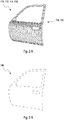
- Figure 1A schematically illustrates a CAD model 110 of a shape 112 of an object 114 in form of a car door 116.
- this shape 112 of the car door 116 may also be denoted as the "original shape" of the car door 116 which is subject to a modification pursuant to the present invention.
- the CAD model 110 is exemplarily defined here by a polygon surface mesh 120.
- other kinds of graphical representation 118 may also be feasible.
- a number of reference landmarks 122 are placed, according to step (a), at a corresponding reference position 124 for each of the reference landmarks 122.
- the number of the reference landmarks 122 and their distribution over the shape 112 of the object 114 may be selected in accordance with a size of the object 114, a complexity of the shape 112 of the object 114, a complexity of the envisaged modification of the shape 112, or a resolution of the shape 112 of the object 114 which is desired at the reference positions 124 of the reference landmarks 122.
- the resolution of the shape 112 has been selected almost equally for all partitions of the car door 116 such that the reference landmarks 122 have been distributed virtually equally over the shape 112 of the car door 116.
- other manners of distributing the reference landmarks 122 may also be feasible.
- each of the reference landmarks 122 have been placed directly at or on the shape 112 of the car door 116 or close to the shape 112 of the car door 116.
- the top left reference landmark 122 has been placed close to the shape 112 of the car door 116 by locating it on a logical construction frame applied to the car door 116, wherein the logic construction frame refers to an additional structure provided to the CAD model 110 in a manner to facilitate the construction of the object 110 by providing at least one simplified reference line or plane configured for providing orientation in generating the shape 112 of the car door 116 in the CAD model 110, especially, in order to reduce an influence of a rounded corner of the car door 116 at the position of the top left reference landmark 122.
- the reference landmarks 122 have been placed at determined points 126, with regard to the shape 112 of the car door 116.
- the term "determined point” refers to a minimum or a maximum of the shape 112 of the car door 116 or of a derivative thereof at the location of the determined point 126.
- all of the determined points 126 relate to a local maximum at rounded corners 128 of the car door 116.
- each of the distinguished points 130 refers here to a point at located on an extension of a boundary line 132 of a reference geometry opening 134 in the car door 116, wherein the particular opening 134 in the car door 116 is designed for receiving a window.
- the distinguished points 130 are located at respective extensions of the boundary line 132 in this exemplary embodiment.
- step (b) may be performed either by converting a corresponding reference landmark 122 into an adjustment landmark 136 or, alternatively, by registering an additional set of adjustment landmarks 136.
- the adjustment landmarks 136 which are located on the right side of the car door 116 are displaced according to step (c) from the reference position 124 where they had been placed in Figure 1B in accordance with step (b) to a modified position 138.
- a displacement 140 between the modified position 138 and the reference position 124 of the actually displaced adjustment landmarks 136 is generated.
- the adjustment landmarks 136 which are located on the left side of the car door 116 are not displaced such that they remain together with the reference landmarks 122 on the reference position 124.
- Figure 1D schematically shows that a partition of the original shape 112 of the car door 116 which is illustrated by dashed lines has been modified during step (d) in order to indicate that the car door 116 now assumes a modified shape 142 as desired.
- the CAD model 110 of the modified shape 142 has been modified by applying a homogenous function of the displacement 140 to the original shape 112 of the car door 116.
- a homogenous curve 144 has been applied as a particular kind of homogenous function in this exemplary embodiment in order to affect the modification of the original shape 112 of the car door 116.
- the homogenous curve 144 which had been laid between the three adjustment landmarks 136 on the right side of the door 116 in Figure 1C has been displaced together with the three corresponding adjustment landmarks 136 during steps (c) and (d), whereby the right side of the original shape 112 of the door 116 has been, correspondingly, modified in order to arrive at the modified shape 142 of the car door 116.
- Using the homogenous curve 144 thus, allows determining the displacements 140 of the car door 116 at arbitrary points located at or on the shape 112 of the car door 116 but between the three corresponding adjustment landmarks 136.
- the application of the homogenous curve 144 to the displacement 140 of the original shape 112 of the car door 116 results in obtaining the CAD model 110 of the modified shape 142 of the car door 116 at each and every arbitrary point located at or on the shape 112 of the car door 116.
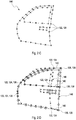
- Figures 2A to 2E illustrate a further, particularly preferred embodiment for the method for determining the modified shape 142 of the CAD model 110 of the car door 116.
- Figure 2A which schematically illustrates the CAD model 110 of the original shape 112 of the object 114 in form of the car door 116, wherein the graphical representation 118 of the car door 116 is exemplarily defined by a polygon surface mesh 120, is identical with the illustration of Figure 1A .
- Figure 2B schematically shows a reference geometry 146 which is adapted to approximate the shape 112 of the car door 116 in the CAD model 110 thereof as depicted in Figure 2A .
- the reference geometry 146 which is related to the original shape of the car door 116 can also be denoted here by the phrase "original reference geometry".
- the reference geometry 146 may, preferably, be obtained by applying a homogeneous approximation function to the original shape 112 of the car door.
- the number of reference landmarks 122 are placed, according to step (a), at the corresponding reference positions 124 for each of the reference landmarks 122 on the reference geometry 146.
- the resolution of the shape 112 has been selected almost equally for all partitions of the car door 116 by distributing the reference landmarks 122 virtually equally over the shape 112 of the car door 116.
- other manners of distributing the reference landmarks 122 over the car door 116 may also be feasible.
- Figure 2D depicts, subsequently, placing exactly one adjustment landmark 136 at the reference position 124 of the corresponding reference landmark 122 according to step (b) and displacing some of the adjustment landmarks 136 from the reference position 124 to a modified position 138 according to step (c).
- the respective displacement 140 between the modified position 138 and the reference position 124 for each adjustment landmark 136 is obtained.
- Figure 2D schematically illustrates, by dashed lines, the original reference geometry 146 approximating the original shape 112 of the car door 116 in the CAD model 110 thereof and, in addition, by solid lines, a modified reference geometry 148 which has been obtained during step (d) by modifying the original reference geometry 146 as desired.
- the homogeneous approximation function which has, preferably, been used for determining the original reference geometry 146 may be applied for this purpose, thus, opening an even easier way to modification compared to Figure 1D .
- the modified reference geometry 148 may, finally, be used for (re-)constructing the CAD model 110 of the modified shape 142 of the car door 116 by applying the homogenous approximation function to the CAD model 110 of the modified shape 142 of the car door 116.
Priority Applications (2)
| Application Number | Priority Date | Filing Date | Title |
|---|---|---|---|
| EP17186548.8A EP3444735A1 (de) | 2017-08-17 | 2017-08-17 | Verfahren und modul zur umwandlung der form eines gegenstands |
| US16/104,186 US11334690B2 (en) | 2017-08-17 | 2018-08-17 | Method for transforming the computer-aided design model of an object |
Applications Claiming Priority (1)
| Application Number | Priority Date | Filing Date | Title |
|---|---|---|---|
| EP17186548.8A EP3444735A1 (de) | 2017-08-17 | 2017-08-17 | Verfahren und modul zur umwandlung der form eines gegenstands |
Publications (1)
| Publication Number | Publication Date |
|---|---|
| EP3444735A1 true EP3444735A1 (de) | 2019-02-20 |
Family
ID=59649559
Family Applications (1)
| Application Number | Title | Priority Date | Filing Date |
|---|---|---|---|
| EP17186548.8A Withdrawn EP3444735A1 (de) | 2017-08-17 | 2017-08-17 | Verfahren und modul zur umwandlung der form eines gegenstands |
Country Status (2)
| Country | Link |
|---|---|
| US (1) | US11334690B2 (de) |
| EP (1) | EP3444735A1 (de) |
Cited By (2)
| Publication number | Priority date | Publication date | Assignee | Title |
|---|---|---|---|---|
| CN111400825A (zh) * | 2020-04-08 | 2020-07-10 | 重庆金康赛力斯新能源汽车设计院有限公司 | 一种抗凹性能仿真方法、装置、存储介质和计算机设备 |
| WO2023232467A1 (de) * | 2022-06-01 | 2023-12-07 | Volkswagen Aktiengesellschaft | Verfahren zur herstellung wenigstens eines bauteils mittels generativer fertigung, und kraftfahrzeug |
Families Citing this family (2)
| Publication number | Priority date | Publication date | Assignee | Title |
|---|---|---|---|---|
| US11861461B2 (en) * | 2018-08-09 | 2024-01-02 | Autodesk, Inc. | Techniques for generating designs that reflect stylistic preferences |
| EP3671660A1 (de) * | 2018-12-20 | 2020-06-24 | Dassault Systèmes | Entwurf eines 3d-modellierten objekts über eine benutzerinteraktion |
Family Cites Families (10)
| Publication number | Priority date | Publication date | Assignee | Title |
|---|---|---|---|---|
| US4821214A (en) * | 1986-04-17 | 1989-04-11 | Brigham Young University | Computer graphics method for changing the shape of a geometric model using free-form deformation |
| US5796400A (en) * | 1995-08-07 | 1998-08-18 | Silicon Graphics, Incorporated | Volume-based free form deformation weighting |
| JP3420884B2 (ja) * | 1996-05-23 | 2003-06-30 | 株式会社ナムコ | 3次元形状モデルの自由形状変形方法、画像合成装置及び情報記憶媒体 |
| US8781557B2 (en) * | 1999-08-11 | 2014-07-15 | Osteoplastics, Llc | Producing a three dimensional model of an implant |
| US6608631B1 (en) * | 2000-05-02 | 2003-08-19 | Pixar Amination Studios | Method, apparatus, and computer program product for geometric warps and deformations |
| US7324103B2 (en) * | 2001-10-30 | 2008-01-29 | Ford Motor Company | System and method of direct mesh manipulation |
| US20070273688A1 (en) * | 2006-05-24 | 2007-11-29 | Yifan Chen | System and method of applying geometric surface features to volumetric CAE mesh models |
| US20120221297A1 (en) * | 2011-02-24 | 2012-08-30 | Siemens Product Lifecycle Management Software, Inc. | Global Deformation for a Modeled Object |
| US9495726B1 (en) * | 2012-05-23 | 2016-11-15 | DEP Autoline, Inc. | System and method for morphing a CAD design element |
| EP3005308B1 (de) * | 2013-06-06 | 2017-10-18 | Vert Rotors UK Limited | Verfahren zur verwendung eines computergrafiksystems zur veränderung der form der oberfläche von modellen geometrischer feststoffe mithilfe von verformung und vorrichtung zur durchführung des verfahrens |
-
2017
- 2017-08-17 EP EP17186548.8A patent/EP3444735A1/de not_active Withdrawn
-
2018
- 2018-08-17 US US16/104,186 patent/US11334690B2/en active Active
Non-Patent Citations (10)
| Title |
|---|
| BOOKSTEIN F.L.: "Principal warps: Thin-plate splines and the decomposition of deformations,", PATTERN ANALYSIS AND MACHINE INTELLIGENCE, IEEE TRANSACTIONS, vol. 11, no. 6, 2002, pages 567 - 585, XP000926355, DOI: doi:10.1109/34.24792 |
| C. LORENZ ET AL: "Generation of Point-Based 3D Statistical Shape Models for Anatomical Objects", COMPUTER VISION AND IMAGE UNDERSTANDING, vol. 77, no. 2, February 2000 (2000-02-01), pages 175 - 191, XP004439301, DOI: 10.1006/CVIU.1999.0814 * |
| C. SINTHANAYOTHIN ET AL: "3D Deformable Mesh Aided Dentistry", 3 September 2015 (2015-09-03), pages 1 - 4, XP055453004, Retrieved from the Internet <URL:https://www.researchgate.net/profile/Chanjira_Sinthanayothin/publication/268043202_3D_Deformable_Mesh_Aided_Dentistry/links/55e7be2508ae65b638995ee6/3D-Deformable-Mesh-Aided-Dentistry.pdf> [retrieved on 20180221] * |
| DANIEL SIEGER; STEFAN MENZEL; MARIO BOTSCH: "Constrained space deformation techniques for design optimization", COMPUTER-AIDED DESIGN, vol. 72, March 2016 (2016-03-01), pages 40 - 51, XP029384737, DOI: doi:10.1016/j.cad.2015.07.004 |
| DOMINIQUE BECHMANN; DOMINIQUE GERBER: "Arbitrary shaped deformations with DOGME", THE VISUAL COMPUTER, vol. 19, 2003, pages 175 - 186 |
| ELLEN DEKKERS; LEIF KOBBELT; RICHARD PAWLICKI; RANDALL C. SMITH: "A Sketching Interface for Feature Curve Recovery of Free-Form Surfaces", COMPUTER-AIDED DESIGN, vol. 43, July 2011 (2011-07-01), pages 771 - 780, XP028218313, DOI: doi:10.1016/j.cad.2010.10.007 |
| JAMES GAIN; DOMINIQUE BECHMANN: "A Survey of Spatial Deformation from a User-Centered Perspective", ACM TRANSACTIONS ON GRAPHICS, vol. 27, no. 4, 2008, XP058098861, DOI: doi:10.1145/1409625.1409629 |
| JEAN-PHILIPPE PERNOT; STEPHANE GUILLET; JEAN-CLAUDE LEON; FRANCE GIANNINI; CHIARA EVA CATALANO; BINACA FALCIDIENO: "A shape deformation tool to model character lines in the early design phases", SMI '02 PROCEEDINGS OF THE SHAPE MODELING INTERNATIONAL, 2002, pages 165, XP002692567, DOI: doi:10.1109/SMI.2002.1003542 |
| THOMAS W. SEDERBERG; SCOTT R. PARRY: "SIGGRAPH '86 Proceedings of the 13th annual conference on Computer graphics and interactive techniques", vol. 20, August 1986, ACM SIGGRAPH COMPUTER GRAPHICS, article "Free-Form Deformation of Solid Geometric Models", pages: 151 - 160 |
| WILLIAM M. HSU; JOHN F. HUGHES; HENRY KAUFMAN: "Direct Manipulation of Free-Form Deformations", COMPUTER GRAPHICS, vol. 26, no. 2, July 1992 (1992-07-01), pages 177 - 184 |
Cited By (2)
| Publication number | Priority date | Publication date | Assignee | Title |
|---|---|---|---|---|
| CN111400825A (zh) * | 2020-04-08 | 2020-07-10 | 重庆金康赛力斯新能源汽车设计院有限公司 | 一种抗凹性能仿真方法、装置、存储介质和计算机设备 |
| WO2023232467A1 (de) * | 2022-06-01 | 2023-12-07 | Volkswagen Aktiengesellschaft | Verfahren zur herstellung wenigstens eines bauteils mittels generativer fertigung, und kraftfahrzeug |
Also Published As
| Publication number | Publication date |
|---|---|
| US11334690B2 (en) | 2022-05-17 |
| US20190057167A1 (en) | 2019-02-21 |
Similar Documents
| Publication | Publication Date | Title |
|---|---|---|
| US11334690B2 (en) | Method for transforming the computer-aided design model of an object | |
| Ding et al. | Automatic multi-direction slicing algorithms for wire based additive manufacturing | |
| Wang et al. | Feature based 3D garment design through 2D sketches | |
| KR100900824B1 (ko) | 스케치 기반 3차원 모델 생성 장치 및 방법 | |
| CN105844711B (zh) | 在细分曲面上雕刻2d图像 | |
| JP2013507679A (ja) | 三次元物体モデルの3dプリントが可能な方法及びシステム | |
| CA2868755A1 (en) | Updating a cad model to reflect global or local shape changes | |
| US9892485B2 (en) | System and method for mesh distance based geometry deformation | |
| Ding et al. | Multi-direction slicing of STL models for robotic wire-feed additive manufacturing | |
| US9495798B2 (en) | Method and device for producing a finite element model | |
| JP2006185444A (ja) | 進化的最適化方法および自由形状変形方法 | |
| CN110176063B (zh) | 一种基于人体拉普拉斯变形的服装变形方法 | |
| Biermann et al. | Direct free-form deformation of NC programs for surface reconstruction and form-error compensation | |
| JP6495728B2 (ja) | 形状変形装置および形状変形用プログラム | |
| EP1301876A2 (de) | System und verfahren zum entwerfen, synthetisieren und analysieren von durch computer erzeugten mechanismen | |
| JP2007172180A (ja) | 設計データ生成装置及び設計データ生成プログラム | |
| EP3735647A1 (de) | System und verfahren zum entwurf und zur herstellung von stationären gitterstrukturen | |
| Sacharow et al. | Iterative, simulation-based shape modification by free-form deformation of the NC programs | |
| CN114119928A (zh) | 一种基于网格操作的肺内器官三维模型优化方法及系统 | |
| JP6449703B2 (ja) | 形状変形装置および形状変形用プログラム | |
| CN106570934A (zh) | 针对大场景的空间隐函数建模方法 | |
| Roth-Koch | Generating CAD models from sketches | |
| JP2009064164A (ja) | 曲面形状作成装置、曲面形状作成方法、及び曲面形状作成プログラム | |
| AU2019371155A1 (en) | Morph target animation | |
| US20240061979A1 (en) | Differentiable parametric computer-assisted design solution |
Legal Events
| Date | Code | Title | Description |
|---|---|---|---|
| PUAI | Public reference made under article 153(3) epc to a published international application that has entered the european phase |
Free format text: ORIGINAL CODE: 0009012 |
|
| STAA | Information on the status of an ep patent application or granted ep patent |
Free format text: STATUS: THE APPLICATION HAS BEEN PUBLISHED |
|
| AK | Designated contracting states |
Kind code of ref document: A1 Designated state(s): AL AT BE BG CH CY CZ DE DK EE ES FI FR GB GR HR HU IE IS IT LI LT LU LV MC MK MT NL NO PL PT RO RS SE SI SK SM TR |
|
| AX | Request for extension of the european patent |
Extension state: BA ME |
|
| STAA | Information on the status of an ep patent application or granted ep patent |
Free format text: STATUS: REQUEST FOR EXAMINATION WAS MADE |
|
| 17P | Request for examination filed |
Effective date: 20190814 |
|
| RBV | Designated contracting states (corrected) |
Designated state(s): AL AT BE BG CH CY CZ DE DK EE ES FI FR GB GR HR HU IE IS IT LI LT LU LV MC MK MT NL NO PL PT RO RS SE SI SK SM TR |
|
| STAA | Information on the status of an ep patent application or granted ep patent |
Free format text: STATUS: EXAMINATION IS IN PROGRESS |
|
| 17Q | First examination report despatched |
Effective date: 20210610 |
|
| STAA | Information on the status of an ep patent application or granted ep patent |
Free format text: STATUS: EXAMINATION IS IN PROGRESS |
|
| STAA | Information on the status of an ep patent application or granted ep patent |
Free format text: STATUS: THE APPLICATION IS DEEMED TO BE WITHDRAWN |
|
| 18D | Application deemed to be withdrawn |
Effective date: 20230803 |