EP3005308B1 - Verfahren zur verwendung eines computergrafiksystems zur veränderung der form der oberfläche von modellen geometrischer feststoffe mithilfe von verformung und vorrichtung zur durchführung des verfahrens - Google Patents
Verfahren zur verwendung eines computergrafiksystems zur veränderung der form der oberfläche von modellen geometrischer feststoffe mithilfe von verformung und vorrichtung zur durchführung des verfahrens Download PDFInfo
- Publication number
- EP3005308B1 EP3005308B1 EP13728799.1A EP13728799A EP3005308B1 EP 3005308 B1 EP3005308 B1 EP 3005308B1 EP 13728799 A EP13728799 A EP 13728799A EP 3005308 B1 EP3005308 B1 EP 3005308B1
- Authority
- EP
- European Patent Office
- Prior art keywords
- geometric
- model
- shape
- solid
- geometric solid
- Prior art date
- Legal status (The legal status is an assumption and is not a legal conclusion. Google has not performed a legal analysis and makes no representation as to the accuracy of the status listed.)
- Active
Links
- 239000007787 solid Substances 0.000 title claims description 617
- 238000000034 method Methods 0.000 title claims description 103
- 239000011265 semifinished product Substances 0.000 claims description 206
- 230000004044 response Effects 0.000 claims description 94
- 238000004519 manufacturing process Methods 0.000 claims description 51
- 238000004364 calculation method Methods 0.000 claims description 30
- 238000010276 construction Methods 0.000 claims description 25
- 230000006870 function Effects 0.000 claims description 19
- 230000008569 process Effects 0.000 claims description 11
- 238000012545 processing Methods 0.000 claims description 7
- 238000012938 design process Methods 0.000 claims description 6
- 230000008859 change Effects 0.000 claims description 4
- 230000007774 longterm Effects 0.000 claims description 3
- 230000013011 mating Effects 0.000 description 102
- 230000003746 surface roughness Effects 0.000 description 17
- 230000001419 dependent effect Effects 0.000 description 14
- 238000011960 computer-aided design Methods 0.000 description 12
- 238000003860 storage Methods 0.000 description 11
- 230000014509 gene expression Effects 0.000 description 9
- 239000013598 vector Substances 0.000 description 9
- 238000013461 design Methods 0.000 description 4
- 238000011161 development Methods 0.000 description 4
- 230000009471 action Effects 0.000 description 3
- 230000015572 biosynthetic process Effects 0.000 description 3
- 230000000694 effects Effects 0.000 description 3
- 238000005516 engineering process Methods 0.000 description 3
- 230000008901 benefit Effects 0.000 description 2
- 238000002474 experimental method Methods 0.000 description 2
- 238000011160 research Methods 0.000 description 2
- 238000012360 testing method Methods 0.000 description 2
- 229910000831 Steel Inorganic materials 0.000 description 1
- 238000005054 agglomeration Methods 0.000 description 1
- 230000002776 aggregation Effects 0.000 description 1
- 239000002775 capsule Substances 0.000 description 1
- 230000005611 electricity Effects 0.000 description 1
- 238000011156 evaluation Methods 0.000 description 1
- 230000002349 favourable effect Effects 0.000 description 1
- 230000002452 interceptive effect Effects 0.000 description 1
- 230000010399 physical interaction Effects 0.000 description 1
- 239000000047 product Substances 0.000 description 1
- 239000010959 steel Substances 0.000 description 1
Images


Classifications
-
- G—PHYSICS
- G06—COMPUTING; CALCULATING OR COUNTING
- G06T—IMAGE DATA PROCESSING OR GENERATION, IN GENERAL
- G06T19/00—Manipulating 3D models or images for computer graphics
- G06T19/20—Editing of 3D images, e.g. changing shapes or colours, aligning objects or positioning parts
-
- G—PHYSICS
- G06—COMPUTING; CALCULATING OR COUNTING
- G06T—IMAGE DATA PROCESSING OR GENERATION, IN GENERAL
- G06T17/00—Three dimensional [3D] modelling, e.g. data description of 3D objects
-
- G—PHYSICS
- G06—COMPUTING; CALCULATING OR COUNTING
- G06T—IMAGE DATA PROCESSING OR GENERATION, IN GENERAL
- G06T17/00—Three dimensional [3D] modelling, e.g. data description of 3D objects
- G06T17/10—Constructive solid geometry [CSG] using solid primitives, e.g. cylinders, cubes
-
- G—PHYSICS
- G06—COMPUTING; CALCULATING OR COUNTING
- G06T—IMAGE DATA PROCESSING OR GENERATION, IN GENERAL
- G06T2219/00—Indexing scheme for manipulating 3D models or images for computer graphics
- G06T2219/20—Indexing scheme for editing of 3D models
- G06T2219/2021—Shape modification
Definitions
- the present invention relates to computer graphics systems which can be used for the automatic geometric construction of models of geometric solids which mate with one another during use as they move relative to one another, and to be more precise to a method for using a computer graphics system for changing the shape of models of geometric solids with the aid of deformation and device for implementing same.
- Document EP 1 594 073 A2 discloses a method to deform a three-dimensional target model using a three-dimensional tool model to cause a change of shape of the target model.
- a three-dimensional tool model to cause a change of shape of the target model.
- Specialist machine tools have been manufactured for this purpose. Only these specialist machine tools should be used to manufacture a specific mating pair of geometric solids.
- pairs of geometric solids which mate with one another as they move relative to one another during use, for example pairs of mating geometric solids of conical rotary compressors, the mating surfaces of which have a complex shape which is impossible to manufacture with precision accuracy for the processing on existing machine tools with numerical control (NC) on the basis of existing generally known laws.
- NC numerical control
- the present invention makes it possible to model geometric solids which mate with one another as they move relative to one another during use and have a complex shape of mating surfaces, and then to manufacture each of these solids with precision for the processing of the mating surfaces (up to 10 micrometres).
- the present invention relates to the generation of parametric models associated with a 3D geometry of mating solids, to be precise to a fourth type of CAD for systems and digital control programs for machine tools with NC.
- the determination of mating parametric models and geometric data of the surfaces of mating solids is integrated in a cycle for constructing set solids, during which the determination of geometric parameters for constructing a first 3D solid is performed, which is used as the basis for constructing a second 3D solid.
- the essential advantage of the present invention consists in that the construction of models of two mating solids is completely interrelated and integrated in one cycle, wherein the two models are completely interrelated.
- AAG Requicha and HB Voelcker have presented an overview of the historical development and an evaluation of CAD (see “ Solid Modeling: A Historical Summary and Contemporary Assessment”, IEEE Computer Graphics and Applications, Vol. 2 No 2, March 1982, pages 9-24 ; see also “ Solid Modeling: Current Status and Research Directions", IEEE Computer Graphics and Applications, October 1983, pages 25-37 ).
- the first of these four directions was the development of a so-called wire-frame graphics system.
- the second type of CAD comprises polygonal graphics systems.
- the third type of CAD comprises relief surface systems.
- the fourth type of CAD comprises methods and systems for modelling a solid which are directed to a representation of complete information relating to solids, specifically to a representation which makes it possible to clearly determine the geometric data of any represented object, wherein these geometric data can be automatically determined computationally.
- Geometric solids with a complex shape include, for example, mating geometric solids of rotary screw compressors (" Tekhnologiya kompressorostroeniya” N.A. Yastrebova, A.I. Kondakov, V.D. Lubenets, A.N. Vinogradov, Moscow, “Mashinostroenie” 1987, pages 15-19 ), which comprise a housing and two conical screws with concave and convex teeth. Several chambers are formed between the surfaces of the two screws, and also between the surfaces of the two screws and the surface of the housing.
- spiral compressors comprising two mating solids in the form of planar spiral screws. Furthermore, one spiral screw is rigidly fixed in a housing, and the other spiral screw is capable of moving with eccentricity around the centre of the first screw. In these compressors, there is also the problem of the leakage of working medium entering gaps between mating elements of the compressor.
- the application WO 8706654 describes a rotary device for compressing gas in refrigerators.
- This device comprises an electric motor having a rotor, which is mounted rotatably within a stator.
- the motor has a hermetically sealed cover and a number of spring elements.
- a compressor comprising two conical screws which mate with one another during use and which directly compress a gaseous medium and have surfaces which mate with one another as they move relative to one another is mounted in the rotor. Furthermore, each screw of the pair of conical screws has a complex shape which is delimited by the complex helical toothed surface. One of the conical screws, during use, performs a complex epicycloidal planetary movement inside the other conical screw.
- each of these screws needs to have a surface which is processed with a high degree of accuracy in order to ensure snug mating of these screws without any gaps as they move relative to one another during use.
- the description of this application does not mention how the described conical screws having the surfaces processed in the mentioned way are produced.
- the inventors of the proposed invention have studied in detail the structural features of these screws described in the application WO 8706654 and have conducted research into the subject of the manufacture of these screws. As a result of the work and experiments which have been performed, the inventors have drawn the conclusion that at present there is no possible way of manufacturing a complex surface of the mating solids with a high precision which ensures snug mating of these solids without any gaps as they move relative to one another during use.
- the problem of producing mating geometric solids of conical rotary compressors consists in the complexity of the surfaces of these solids and the absence of a generally known mathematical expression describing the generatix of the profiles of the surfaces of the mating geometric solids on a plane perpendicular to the axis of a conical semifinished product of a corresponding geometric solid.
- NC Tekhnologiya kompressorostroeniya
- said machine tools do not ensure a surface roughness of up to 10 micrometres along the lines of contact between two mating helical solids having a complex shape which is limited by the complex helical toothed surface as they move relative to one another during use.
- a device and a method for using a computer graphics system for deforming the shape of the surface of models of geometric solids by automatic geometric construction of models of geometric solids for subsequent production of said geometric solids are known from the patent US 8112256 .
- the geometric solids are manufactured by connecting small objects to form large objects.
- the fixed arrangement of these objects together comprises complex initial movements of a large quantity of separate small objects.
- the fixed mounting of these objects together comprises a combination of physical interactions which are dependent not only on the objects themselves, but also on the topology of the overall structure and the mutual arrangement which the objects assume within this topology.
- This device and this method solve the problem of constructing models of three-dimensional objects using computer graphics, such as urban agglomerations comprising buildings and building complexes, industrial enterprises and electricity plants, oil derricks, aircraft, automobiles, trains, ships, satellites and airships, microchips, nanotechnological structures and the like for subsequent production thereof.
- computer graphics such as urban agglomerations comprising buildings and building complexes, industrial enterprises and electricity plants, oil derricks, aircraft, automobiles, trains, ships, satellites and airships, microchips, nanotechnological structures and the like for subsequent production thereof.
- this patent describes a method and a device for automatically designing a fixed arrangement of separate objects in an overall structure of entire objects in such a way that the objects are combined with one another without the use of a user interface, for example a keyboard or a monitor.
- This method and this device make it possible for a user to produce a design of large objects with different variants for the mutual fixed arrangement of the small objects contained within them.
- This method can be implemented in the device with the aid of any known computer graphics system suitable for implementing the steps in this method.
- any graphics system of a conventional computer can be controlled with the aid of this method.
- This device comprises a central processor capable of generating a plurality of bases in a coordinates reading system, each of which bases comprises a local system of coordinates.
- the central processor is connected to an initializer and an information input means (keyboard or any other known information input means).
- This processor is capable of producing a corresponding model of a geometric solid in a local system of coordinates of each of the pluarality of bases according to at least one mathematical law having a variable of a representative of a corresponding base, wherein each model of the geometric solid of the content has a shape which is dependent on the value of the variable of the representative of the corresponding base in which it is located, wherein the shape of the models of the geometric solid changes from base to base in accordance with the values of the variables.
- the central processor has an external memory, which comprises programmed instructions with the aid of which the processor automatically implements some of the steps in the proposed method, and an internal memory, which comprises certain data input by the user and/or intermediate results which the processor requires for its operation.
- the programmed instructions which are input into the external memory of the central processor comprise a program for storing input data and a mathematical law which has a variable of a representative of a corresponding base and ensures the production of the shape of each model of the geometric solid of the content, which shape is dependent on the value of the variable of the representative of the corresponding base in which it is located, wherein the shape of the models of the geometric solid changes from base to base in accordance with the values of the variables.
- the device comprises a graphical monitor and an information input means, which are connected to the central processor. Models of the geometric solid during the design process are visualized on the monitor.
- This method and this device make it possible for a user to produce models of designs of large objects with different variants for the mutual fixed arrangement of the small objects contained within them.
- a method and a device for using a computer graphics system for changing the shape of the surface of a model of a geometric solid with the aid of deformation are known from the patent US 4821214 .
- This method and this device are used for designing models of geometric solids, that is for applying a computer graphics system for changing the shape of the surface of models of geometric solids with the aid of deformation.
- This method and this device can be used for producing a deformed shape of models of geometric solids which permanently mate with one another during use.
- This method can be implemented in this device with the aid of any known computer graphics system suitable for implementing the steps in this method.
- any graphics system of a conventional computer can be controlled with the aid of this method.
- This device comprises a central processor, which is connected to an initializer and an information input means (keyboard or any other known information input means).
- the central processor has an external memory, which comprises programmed instructions with the aid of which the processor implements some of the steps in the proposed method, and an internal memory, which comprises certain data or intermediate results which the processor requires for its operation.
- the programmed instructions which are input into the external memory of the central processor comprise a program for storing input data and a control-point grid for controlling deformations of semifinished products of models of geometric solids.
- the device comprises a graphical monitor which is connected to the information input means and to the central processor. A model of a geometric solid during the design process is visualized on the monitor.
- This method for using a computer graphics system for changing the shape of models of geometric solids with the aid of deformation comprises the following steps: inputting into a processor and storing several characteristics defining the geometry of the shape of the surface of a model of a semifinished product of a first geometric solid in a global system of coordinates; inputting into the processor and storing several characteristics defining the geometry of the shape of the surface of a model of a semifinished product of a second geometric solid in a local system of coordinates; producing geometric data for each point on the surface of the model of the semifinished product of the first geometric solid in the global system of coordinates and geometric data for each point on the surface of the model of the semifinished product of the second geometric solid in the local system of coordinates; constructing a model of the semifinished product of the first geometric solid in the global system of coordinates on the basis of the geometric data produced, with the aid of the processor in response to a user command; applying a deformation to the model of the semifinished product of the first geometric solid by changing the shape of the surface of the model of
- the user Prior to implementing this method, the user sets a geometric solid for which a model needs to be designed and also determines the shape of the semifinished product which needs to be deformed in order to produce this geometric solid.
- the semifinished product used can be a solid having any desired shape for which there is at present a mathematical law which describes the surface of this solid.
- the user initially calculates geometric data defining the semifinished product of the solid-state geometric solid relative to the global system of coordinates on the basis of known mathematical laws.
- the shape of the model of the semifinished product of the geometric solid comprises a generally known figure, for example a cube, a parallelepiped, a sphere, a cone, a torus, a prism, a capsule, an icosahedron, an octahedron or similar geometric figures.
- the central processor is brought into action and the user uses the keyboard to input the calculated geometric data relating to the semifinished product into the central processor.
- the central processor writes the input geometric data to the internal memory, and then constructs a semifinished product of the geometric model which needs to be deformed with the aid of this method.
- Geometric data refers to data which are input and stored in the processor in order to define any geometric model in relation to the global system of coordinates.
- Geometric data can include data of several points for which the coordinates are expressed in terms of the global system of coordinates or data with any function which defines parametric curves or the shape of the surface of a geometric model expressed in terms of the coordinate axes of the global system of coordinates.
- the user uses the keyboard to input into the processor and to store a local system of coordinates which defines a region of deformation of the model and lays a control-point grid over part of the model in the deformation region for controlling the deformation of this part of the model.
- the user performs, manually with the aid of the processor, the deformation of the model in the deformation region by means of manually shifting one of the control points relative to another control point in the grid, produces geometric data of the shifted control points in the processor and uses the processor to convert the geometric data produced of the shifted control points in such a way that they are expressed in terms of the local system of coordinates. After this, the user determines that part of the geometric data produced which is in the deformation region.
- the deformation steps can be displayed on a monitor.
- the finished deformed target model can be stored in the internal memory of the central processor and output to an external storage device, for example a magnetic strip storage device or the output of a printer/plotter, solid-state storage device or other similar means.
- the user uses the processor to determine and store the geometric data of the deformed position of the deformed model produced in the deformation region, thereby using the law of deformation for the converted geometric data determined in the deformation region.
- the law of deformation is used which is a trivariate vector rational polynomial, in which each moved control point is a coefficient of the polynomial.
- the user uses the processor to display the deformed target model in correspondence to the deformation of each moved control point on the graphical monitor.
- the user uses the processor to classify the several points within the global system of coordinates for determining and storing the moved points which are located on the surface of, beyond the bounds of and within the deformed solid-state model.
- the user uses the keyboard to input into the internal memory of the processor and to store therein additional geometric data which define other solid-state models, whereupon the user manually, with the aid of the processor, subsequently changes the shape of the displayed model by means of Boolean logic.
- Boolean logic should in this case be understood to mean the removal of part of one of the models of the solid-state geometric solids at the point of intersection (interference) of two solid-state models of geometric solids.
- This method and this device make it possible to produce models of fixed geometric solids having surfaces with any complexity by manually moving, with the aid of a processor, points on the surface of a model to be deformed that correspond to control points in the grid.
- said method and said device do not provide the possibility of producing models of geometric solids which mate with one another during use as they move relative to one another.
- the present invention is based on the problem of providing a method and a device for using a computer graphics system for changing the shape of the surface of models of geometric solids with the aid of deformation by such means and with such features as would make it possible to produce a deformed shape of the surface of models of geometric solids for the subsequent production thereof that would provide the possibility of producing geometric solids having a complex shape of mating surfaces processed with a precision (with a surface roughness of up to 10 micrometres) which ensures snug mating of the geometric solids without any gaps as they move relative to one another during use, which makes it possible to use the proposed invention, inter alia, for simplifying the production of conical screws of rotary screw compressors using standard equipment, for example a machine tool plant with program control already in existence in the industry at present.
- the proposed method makes it possible to model geometric solids which mate with one another during use as they move relative to one another and which have, inter alia, a complex shape of the mating surfaces, and then to manufacture each of these solids with a roughness of the mating surfaces of up to 10 micrometres.
- the deformation is performed by moving the models in accordance with a law imitating the movement of the geometric solids which mate with one another during use, as a result of which the possibility of producing precision of the surfaces of the first and second geometric solids and the possibility of said geometric solids mating with one another without any gaps as they move relative to one another during use are provided.
- the proposed method makes it possible to produce complete and accurate geometric data relating to each point on the surface of each mating solid, which geometric data provide the possibility of manufacturing mating geometric solids having, inter alia, a complex shape of the mating surfaces processed with a precision (with a surface roughness of up to 10 micrometres) which ensures snug mating of the geometric solids without any gaps as they move relative to one another during use.
- the proposed method includes the following steps: inputting into the processor and storing several characteristics defining the geometry of the shape of the surface of the first geometric solid in a first system of coordinates with the start of the coordinates at point O; inputting into the processor and storing several characteristics defining the geometry of the shape of the surface of the model of the semifinished product of the first geometric solid in the first system of coordinates; inputting into the processor and storing several characteristics defining the geometry of the shape of the surface of the second geometric solid, which mates with the first geometric solid during use as they move relative to one another, in a second system of coordinates with the start of the coordinates at point A; inputting into the processor and storing several characteristics defining the geometry of the shape of the surface of the model of the semifinished product of the second geometric solid in the second system of coordinates; inputting the into the processor and storing several mathematical laws for the automatic calculation, on the basis of the several characteristics, of the geometric data for each point on the surface of the model of the semifinished product of the first geometric solid in the first system
- the possibility is provided of producing two or more functional geometric solids which mate with one another as they move relative to one another during use and which have precision accuracy of the mating surfaces and the possibility of said geometric solids mating with one another without any gaps as they move relative to one another.
- the model of each of the semifinished products In order to save on the amount of time spent on producing the geometric data, it is expedient for the model of each of the semifinished products to have dimensions which make it possible to insert the corresponding target model of the corresponding geometric solid into each corresponding model of the semifinished product.
- the following steps are preferably additionally implemented: using the processor to display, in response to a user command, the surface of the model of the semifinished product of the first solid in the first system of coordinates; using the processor to display, in response to a user command, the model of the at least one first tool in the second system of coordinates; using the processor to display, in response to a user command, the surface of the deformed target model of the first solid in the first system of coordinates; using the processor to display, in response to a user command, the surface of the model of the semifinished product of the second solid in the second system of coordinates; using the processor to display, in response to a user command, the surface of the deformed target model of the second geometric solid in the second system of coordinates.
- a first conical screw is selected as the first geometric solid;
- a second conical screw which has one tooth more than the first conical screw is selected as the second geometric solid, which mates with the first geometric solid as they move relative to one another during use;
- at least the length, the maximum diameter, the minimum diameter, the number of turns of the spiral toothed surface, the number of teeth, and the height of each tooth of the first conical screw are introduced as the several characteristics defining the geometry of the shape of the surface of the target model of the first conical screw;
- at least the height and diameter of each base of a first truncated cone are introduced as the several characteristics defining the geometry of the shape of the surface of the model of the semifinished product of the first conical screw;
- a device for using a computer graphics system for changing the shape of the surfaces of models of geometric solids with the aid of deformation and producing a deformed shape of the surfaces of target models of at least a first and a second geometric solid, which geometric solids mate with one another during use as they move relative to one another, for subsequent production of said geometric solids said device comprising: a central processor, which has, connected to one another, an internal memory and an external memory and which is capable of receiving, processing and storing updated and long-term information; an information input means, which is connected to the central processor; an information output means, which is connected to the central processor, wherein, in accordance with the invention, the proposed device is intended for producing a deformed shape of the surfaces of the target models of at least the first and second geometric solids, which mate with one another during use as they move relative to one another, for the subsequent production of said geometric solids, and has the external memory of the central processor, which external memory comprises at least a program for storing input data, including:
- the proposed device makes it possible to model geometric solids which mate with one another during use as they move relative to one another and which have, inter alia, a very complex shape of the mating surfaces, and then to manufacture each of these solids with a roughness of the mating surfaces of up to 10 micrometres.
- the deformation is performed by moving the models in accordance with a law imitating the movement of the geometric solids which mate with one another during use and, in the proposed device, the possibility of producing precision accuracy of the surfaces of the first and second geometric solids and the possibility of said geometric solids mating with one another without any gaps as they move relative to one another during use are provided.
- the proposed device makes it possible to produce complete and accurate geometric data relating to each point on the surface of each mating solid, which geometric data provide the possibility of manufacturing mating geometric solids having, inter alia, a very complex shape of the mating surfaces processed with a precision (with a surface roughness of up to 10 micrometres) which ensures snug mating of the geometric solids without any gaps as they move relative to one another during use.
- the proposed device In order to visually observe the process of producing deformed shapes of models of geometric solids which mate with one another during use, it is desirable for the proposed device to comprise a graphical monitor, which is connected to the information input means and to the central processor and is capable of visualizing the models of the geometric solids during the design process.
- the information output means is expedient for the information output means to be connected to the input of a numerical control means of a device for producing the geometric solids.
- the proposed method for using a computer graphics system for changing the shape of the surface of models of geometric solids with the aid of deformation is intended for producing a deformed shape of models of geometric solids, which mate with one another as they move relative to one another during use, for the subsequent production of said geometric solids.
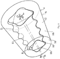
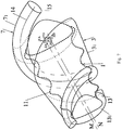
- the user Prior to implementing the proposed method, the user sets the shape of at least a first geometric solid 1 ( Figure 1 ) and a second geometric solid 2 ( Figure 2 ), which need to be manufactured using the proposed method and which should mate with one another during use as they move relative to one another and have a precision accuracy of the mating surfaces with a surface roughness of up to 10 micrometres which ensures snug mating of these solids 1, 2 ( Figures 1 and 2 ) without any gaps as they move relative to one another during use.
- Geometric solids having any desired surface shape can be used as the geometric solids 1, 2.
- geometric solids having a complex surface shape are selected as the geometric solids 1, 2, for example, conical screws of a rotary screw compressor unit, gear elements, gears of a gear pump and similar pairs of geometric solids which mate with one another as they move relative to one another during use.
- the characteristics of the first geometric solid 1 are dependent on the characteristics of the second geometric solid 2, or vice versa, since these characteristics relate to two solids 1, 2 which will mate with one another during use as they move relative to one another once they have been produced.
- the user sets the geometry of the shape of the surface of the semifinished product 3 ( Figure 1 ) of the first geometric solid 1 and the geometry of the shape of the surface of the semifinished product 4 ( Figure 2 ) of the second geometric solid 2.
- a different number of geometric solids a different number of semifinished products is used, which is equal to the number of geometric solids.
- Each of the several first mathematical laws is dependent on the shape of the geometric solids which mate with one another during use as they move relative to one another and comprises a known mathematical law.
- a specific exemplary embodiment of the proposed method for specific mating geometric solids 1, 2 is set forth below, with the corresponding mathematical laws being cited.
- a number of models 7 1 of the first tools 7 for producing a deformed shape of the surface of the target model of the first geometric solid 1 is dependent on the complexity of the shape of the surface of the geometric solids 1, 2.
- the arrangement of the first and second systems of coordinates is determined by determining the first start for the coordinates, for example at point O ( Figure 1 ), and the second start of the coordinates, for example at point A ( Figure 2 ).
- Points O and A can be arranged at any location in the region of the computer graphics system which makes it possible to create two systems of coordinates which are dependent on the movement, relative to one another, of geometric solids 1, 2 which mate with one another during use.
- points O and A can lie on the longitudinal axes N and M of the corresponding models 3 1 , 4 1 of the semifinished products 3, 4 of the first and second solids 1, 2, as shown in Figures 1 and 2 .
- the models 3 1 , 4 1 of the semifinished products 3, 4 should at least remotely resemble the corresponding geometric solids 1, 2 (as illustrated in Figures 1 and 2 ) and should have dimensions which make it possible to insert the corresponding target model of the corresponding geometric solid 1, 2 into each corresponding model 3 1 , 4 1 of the semifinished products 3, 4.
- Each of the several second mathematical laws represents a corresponding and known polynomial in which at least one of the coefficients represents one of the several characteristics defining the geometry of the shape of the surface of the second geometric solid 2 in the second system of coordinates.
- This polynomial is dependent on the shape of the geometric solids which mate with one another during use as they move relative to one another and corresponds to a known mathematical formula which describes part of the surface of one of the mating solids.
- geometric data is intended to mean a complete description of the surface of any geometric solid 1, 2 with the aid of the coordinates of all of the points forming the surface of this geometric solid 1, 2.
- the surface of the model 3 1 of the semifinished product 3 of the first geometric solid 1 in the first system of coordinates is constructed with the aid of the processor in response to a user command.
- geometric data for each point on a directrix 5 and geometric data for each point on a generatrix 6, which directrix and generatrix form a surface defining the shape of a model 7 1 of at least one first tool 7 having at least part of a surfaces which imitates at least part of the surface of the second geometric solid 2 are produced.
- the construction on the basis of the geometric data produced, with the aid of the processor, in response to a user command, of the surface defining the shape of the model 7 1 of the at least one first tool 7 for controlling the deformation of the model 3 1 of the semifinished product 3 of the first geometric solid 1 in the second system of coordinates is performed.
- the application of a deformation to the model 3 1 of the semifinished product 3 of the first geometric solid 1 with the aid of the processor in response to a user command, by moving, relative to one another, the model 7 1 of the at least one first tool 7 and the model 3 1 of the semifinished product 3 of the first geometric solid 1 in accordance with a law for a movement imitating the movement during use of the first geometric solid 1, which mates with the second geometric solid 2 as they move relative to one another, by introducing the model 7 1 of the at least one first tool 7 into the model 3 1 of the semifinished product 3 of the first geometric solid 1, and by changing the shape of the surface of the model 3 1 of the semifinished product 3 of the first geometric solid 1 with the aid of Boolean logic until the deformed shape of the surface of the target model 8 ( Figures 1 and 4 ) of the first geometric solid 1 is produced, which deformed shape has the several characteristics defining the geometry of the shape of the surface of the first geometric solid 1, is performed.
- the determination and storage, with the aid of the processor, in response to a user command, of the geometric data for each point on the surface defining the deformed shape of the surface of the target model 8 of the first geometric solid 1 in the first system of coordinates are performed.
- the target model 8 of the first geometric solid 1, which target model has the deformed shape of the surface, is used as the model 10 1 ( Figure 4 ) of the second tool 10 for producing the deformed shape of the surface of the target model 9 ( Figures 2 and 5 ) of the second geometric solid 2.
- the determination and storage, with the aid of the processor, in response to a user command, of the geometric data for each point on the surface defining the deformed shape of the surface of the target model 9 of the second geometric solid 2 in the second system of coordinates are performed.
- geometric data for each point on the surface defining the deformed shapes of the surfaces of the target models 8, 9 of the first and second geometric solids 1, 2, respectively, are automatically produced.
- the proposed method makes it possible to solve the problem of the provision and simplification of the production of geometric solids which mate with one another as they move relative to one another during use and have a complex surface shape, for example gears, conical screws of a rotary screw compressor unit, gears of a gear pump and similar mating pairs of geometric solids.
- the proposed method makes it possible to produce mating geometric solids having a precision accuracy of the mating surfaces which rules out the possibility of the formation of gaps between the mating surfaces and which provides the possibility of high-precision mating of these solids during use.
- the proposed method eliminates the need for the use of specialist machine tools for the production of each geometric solid and makes it possible to use a machine tool plant with NC which is already in existence at present for implementing the method.
- geometric data for each point on the surface defining the deformed shape of the surface of the target model 8 of the first geometric solid 1 in the first system of coordinates and geometric data for each point on the surface defining the deformed shape of the surface of the target model 9 of the second geometric solid 2 in the second system of coordinates are output to the input of a numerical control means of a device (not shown in the drawing) for producing said geometric solids 1, 2.
- geometric data for each point on the surface defining the deformed target shape of the model 8 of the first geometric solid 1 and geometric data for each point on the surface defining the deformed target shape of the model 9 of the second solid 2 can be output to a 3D printer or similar means or to an external storage device, for example a magnetic strip storage device or a solid-state storage device, for use for the subsequent production of the first and second geometric solids 1, 2.
- the following steps are additionally implemented: using the processor to display, in response to a user command, the surface of the model 3 1 of the semifinished product 3 of the first solid 1 in the first system of coordinates; using the processor to display, in response to a user command, the model 7 1 of the at least one first tool 7 in the second system of coordinates; using the processor to display, in response to a user command, the surface of the deformed target model 8 of the first solid 1 in the first system of coordinates; using the processor to display, in response to a user command, the surface of the model 4 1 of the semifinished product 4 of the second solid 2 in the second system of coordinates; using the processor to display, in response to a user command, the surface of the deformed target model 9 of the second solid 2 in the second system of coordinates.
- a model of a geometric solid having a simple surface shape is selected as each model 3 1 , 4 1 of the semifinished product 3, 4.
- the proposed method can be used for producing deformed target shapes of models of a first and a second geometric solid, which geometric solids comprise conical screws 11, 12 ( Figure 6 ) of rotary screw compressors having a conical helical spiral toothed surface, which is processed with a precision accuracy of the mating surfaces which ensures that there are no gaps when these solids mate with one another as they move relative to one another during use.
- first conical screw 11 is selected as the first geometric solid
- second conical screw 12 which has one tooth more than the first conical screw 11 is selected as the second geometric solid, which mates with the first geometric solid as they move relative to one another during use, wherein the model 7 1 of one first tool 7 is used.
- At least the length of the first conical screw 11, the maximum and minimum diameters of the first conical screw 11, the number of turns of the spiral toothed surface, the number of teeth of the first conical screw 11 and the height of each tooth of the first conical screw 11 are introduced as the several characteristics defining the geometry of the shape of the surface of the first conical screw 11.
- the characteristic of the roughness of this surface or any other characteristic selected, for example, from the group consisting of the characteristic of the spiral toothed surface (equal pitch or variable pitch) of the first conical screw 11, the average diameter of the spiral toothed surface of the first conical screw 11, the ratio of the maximum to the minimum diameter of this spiral toothed surface, the initial angle of inclination of this spiral toothed surface or length of the spiral toothed surface of the first conical screw 11, can additionally be introduced as the several characteristics defining the geometry of the shape of the surface of the first conical screw 11.
- At least the height and the diameter of each base of a first truncated cone 13 are introduced as the several characteristics defining the geometry of the shape of the surface of a model 13 1 ( Figure 1 ) of the semifinished product of the first conical screw 11.
- the length, the maximum diameter, the minimum diameter, the number of turns, the number of teeth and the height of each tooth of the second conical screw 12 are introduced as the several characteristics defining the geometry of the second conical screw 12.
- a conical spiral 14 ( Figure 3 ), which represents a helical conical directrix which is constructed on the basis of the characteristics of the second solid 2, is used as the directrix 5, which forms the surface defining the shape of the model 7 1 of the first tool 7.
- a circle 15 ( Figure 3 ), which comprises a closed planar simple curve is used as the generatrix 6, which forms the surface defining the shape of the model 7 1 of the first tool 7.
- a model of one first tool 7 is used in this example, but if necessary models of several first tools can be used.
- the geometric data for each point on the conical spiral 14 and the geometric data for each point on the circle 15, which conical spiral and circle form the surface defining the shape of the model 7 1 of the first tool 7 which has at least part of the surface which imitates at least part of the surface of the second conical screw 12, are produced as the geometric data for each point on the surface defining the shape of the model 7 1 of the first tool 7.
- part of the surface of the model 7 1 of the first tool 7 corresponds to the radius of the apex of the tooth along the entire length of the second conical screw 12.
- this part of the surface or the entire surface can correspond to other parameters of the shape of the target model.
- the construction of the surface defining the shape of the model 7 1 of the first tool 7 on the basis of the geometric data produced with the aid of the processor in response to a user command is performed in order to control the deformation of the first truncated cone 13 ( Figure 7 ) in the second system of coordinates.
- the movement, relative to one another, of the model 7 1 ( Figure 7 ) of the first tool 7 produced and the first truncated cone 13 is performed on the basis of a law for a cycloidal movement which imitates the movement during use of the first conical screw 11.
- a deformed shape of the surface of the target model 8 1 of the first conical screw 11 is produced as the deformed shape of the surface of the target model 8 of the first solid 1, said deformed shape having the abovementioned several characteristics.
- Geometric data for each point on the surface defining the deformed shape of the surface of the target model 8 1 of the first conical screw 11 are determined and stored as the geometric data for each point on the surface defining the deformed shape of the surface of the target model 8 of the first solid 1.
- each base of the second truncated cone 16 ( Figure 6 ) are introduced as the several characteristics defining the geometry of the shape of the surface of the model 16 1 ( Figure 6 ) of the semifinished product of the second conical screw 12.
- the characteristic of the surface roughness or any other characteristic can be introduced as the several characteristics defining the geometry of the shape of the surface of this model 16 1 .
- the target model 8 1 ( Figure 4 ) of the first conical screw 11, which target model has the deformed shape of the surface, is used as the model 10 1 of the second tool 10.
- the movement, relative to one another, of the target model 8 1 of the first conical screw 11 and the second truncated cone 16 is performed in accordance with a law for a cycloidal movement imitating the movement during use of the second conical screw 12, which mates with the first conical screw 11 as they move relative to one another.
- the deformed shape of the surface of the target model 9 1 of the second conical screw 12 is produced as the deformed shape of the surface of the target model 9 of the second solid 2, said deformed shape having the abovementioned several characteristics.
- Geometric data for each point on the surface defining the deformed shape of the surface of the target model 9 1 of the second conical screw 12 are determined and stored as the geometric data for each point on the surface defining the deformed shape of the surface of the target model 9 of the second geometric solid 2.
- FIG. 8 A flowchart for implementing the proposed method is illustrated in Figure 8 (a, b, c , d, e, f, g).
- the use of the proposed method makes it possible to produce geometric data for each point on the surfaces defining the deformed shapes of the surfaces of the target models 8 1 , 9 1 ( Figure 4 and Figure 5 ) of the first and second conical screws 11, 12.
- the presence of these geometric data provides the possibility of producing conical screws having a complex shape of the mating surfaces with a surface roughness of up to 10 micrometres, that is surfaces which are processed with a precision which ensures snug mating of these screws without any gaps as they move relative to one another during use.
- the proposed method makes it possible to use the proposed invention for simplifying the production of conical screws of rotary screw compressors using standard equipment, for example a machine tool plant with program control which is already in existence at present in the industry.
- the main advantage of the proposed method consists in that the deformation of the models 3 1 , 4 1 of the semifinished products 3, 4 of the first and second geometric solids 1, 2 is performed with the aid of a model of the corresponding tool 7, 10.
- a model 7 1 of at least one first tool 7 is used as the model of the tool for producing the deformed shape of the surface of the target model 8 of the first geometric solid 1.
- geometric data for each point on the directrix 5 and geometric data for each point on the generatrix 6, which directrix and generatix form the surface defining the shape of the model 7 1 of the first tool 7, are automatically calculated. This is performed with the aid of a processor in response to a user command using several mathematical laws, each of which comprises a polynomial in which at least one of the coefficients represents one of the several characteristics defining the geometry of the shape of the surface of the second geometric solid 2.
- the deformation of the model 3 1 of the semifinished product 3 of the first geometric solid 1 is performed with the aid of a processor in response to a user command by moving, relative to one another, a model 7 1 of the at least one first tool 7 and the model 3 1 of the semifinished product 3 of the first geometric solid 1 in accordance with a law for a movement imitating the movement during use of the first geometric solid 1, which mates with the second geometric solid 2 as they move relative to one another, by introducing the model 7 1 of the at least one first tool 7 into the model 3 1 of the semifinished product 3 of the first geometric solid 1, and by changing the shape of the surface of the model 3 1 of the semifinished product 3 of the first geometric solid 1 with the aid of Boolean logic until the deformed shape of the surface of the target model 8 of the first geometric solid 1 is produced.
- a target model 8 of the first geometric solid 1, said target model having a deformed surface shape, is used as the model 10 1 of the second tool 10 for producing the deformed shape of the surface of the target model 9 of the second geometric solid 2.
- the deformation of the model 4 1 of the semifinished product of the second geometric solid 2 is performed with the aid of a processor in response to a user command by moving, relative to one another, the model 10 1 of the second tool 10 and the model 4 1 of the semifinished product 4 of the second geometric solid 2 in accordance with a law for a movement imitating the movement during use of the second geometric solid 2, which mates with the first geometric solid 1 as they move relative to one another, by introducing the model 10 1 of the second tool 10 into the model 4 1 of the semifinished product 4 of the second geometric solid 2, and by changing the shape of the surface of the model 4 1 of the semifinished product 4 of the second geometric solid 2 with the aid of Boolean logic until the deformed shape of the surface of the target model 9 of the second geometric solid 2 is produced.
- the determination and storage, with the aid of a processor, in response to a user command, of geometric data for each point on the surface defining the deformed shape of the surface of the target model 8 of the first geometric solid 1 and the deformed shape of the surface of the target model 9 of the second geometric solid, respectively, are performed.
- the proposed method will be considered in more detail in the description relating to the operation of the proposed device.
- the proposed method for using a computer graphics system for changing the shape of the surface of models of geometric solids with the aid of deformation can be implemented in the proposed device with the aid of any known computer graphics system suitable for implementing the abovementioned steps in this method.
- the proposed device is intended for the automatic design of complex three-dimensional objects without using a file development framework and makes it possible for the user to produce deformed shapes of target models of various geometric solids.
- the proposed device which uses a computer graphics system for changing the shape of the surface of models of geometric solids with the aid of deformation, is intended for producing a deformed shape of surfaces of target models 8, 9 of at least a first and a second geometric solid 1, 2, which geometric solids mate with one another during use as they move relative to one another, for the subsequent production of said geometric solids.
- the proposed device comprises a central processor 17 ( Figure 9 ), which has, connected to one another, an internal memory 18 and an external memory 19 and which is capable of receiving, processing and storing updated and long-term information.
- the proposed device comprises an information input means 20, for example a keyboard (not shown in the drawing), and an information output means 21, with it being possible for any desired known means intended for similar purposes, for example, to be used as said information output means, said information input means and said information output means being connected to the central processor 17.
- the external memory 19 of the central processor 17 comprises at least a program for storing input data, including:
- the internal memory 18 of the central processor 17 contains certain data and/or intermediate results which the processor 17 requires for its operation, and which include at least:
- the central processor 17 is capable of performing the following steps:
- the proposed device comprises a graphical monitor (not shown in the drawing), which is connected to the central processor 17 and is capable of visualizing the models of the geometric solids 1, 2 during the design process.
- the information output means 21 is connected to the input of a numerical control means of a device for producing geometric solids (not shown in the drawing).
- a machine tool with NC or a 3D printer or any other known device intended for similar purposes can be used as the device for producing geometric solids.
- An initializer of a computer graphics system (not shown in the drawing) for automatically bringing said computer graphics system into action can be connected to the central processor 17.
- the proposed device makes it possible to model geometric solids which mate with one another as they move relative to one another during use and which have, inter alia, a very complex shape of the mating surfaces, and then to manufacture each of these solids with a roughness of the mating surfaces of up to 10 micrometres.
- the deformation is performed by moving the models in accordance with a law imitating the movement of the geometric solids, which mate with one another during use, as a result of which the possibility of producing precision of the surfaces of the first and second geometric solids and the possibility of said geometric solids mating with one another without any gaps as they move relative to one another during use are provided.
- the proposed device makes it possible to produce complete and accurate geometric data relating to each point on the surface of each mating geometric solid, which geometric data provide the possibility of manufacturing mating geometric solids having, inter alia, a very complex shape of the mating surfaces processed with a precision (with a surface roughness of up to 10 micrometres) which ensures snug mating of the geometric solids without any gaps as they move relative to one another during use. This is explained by the automatic calculation by means of the processor of all the geometric data.
- the user selects a first conical screw 11 and a second conical screw 12, which has one tooth more than the first conical screw 11, as the first geometric solid 1 and the second geometric solid 2.
- the first conical screw 11 and the second conical screw 12 represent set geometric solids which mate with one another during use as they move relative to one another and have set dimensions, set characteristics and a set precision for the roughness of the mating surfaces, that is geometric solids which are intended to be produced using the proposed invention.
- the characteristics of the first conical screw 11 are dependent on the characteristics of the second conical screw 12, or vice versa, since these characteristics relate to two geometric solids which will mate with one another during use as they move relative to one another once they have been produced.
- the models 13 1 , 16 1 of the semifinished products 13, 16 of the first and second conical screws 11, 12 should at least remotely resemble the corresponding first and second conical screws 11, 12 (as illustrated in Figure 1 and Figure 2 ) and should have dimensions which make it possible to insert the target model 8 1 , 9 1 of the corresponding conical screw 11, 12 into each corresponding model 13 1 , 16 1 of the semifinished products 13, 16 of the first and second conical screws 11, 12.
- a first and a second truncated cone 13, 16 are used as the semifinished products 13, 16 of the first and second conical screws 11, 12, respectively.
- the central processor 17 is brought into action with the aid of the initializer of the computer graphics system.
- the user inputs several characteristics defining the geometry of the shape of the surface of the first conical screw 11 into the processor 17.
- the number of teeth of the first conical screw 11, the length of this screw 11, the height of the teeth of this screw 11, the greatest and smallest diameter of the spiral toothed surface of the first truncated cone 13, which is used as the model 13 1 of the semifinished product 13 of the first conical screw 11 and the number of turns of the spiral toothed surface along the length of the first truncated cone 13 are input as these characteristics.
- the processor 17 stores the input characteristics of the first conical screw 11 in the internal memory 18 for subsequent use.
- the user inputs several characteristics defining the geometry of the shape of the surface of the first truncated cone 13 into the processor.
- the height of the first truncated cone 13 and the greatest and smallest diameter of the bases of the first truncated cone 13 are input as these characteristics.
- the processor 20 stores the input characteristics of the first truncated cone 13 in the internal memory 18 for subsequent use.
- the user inputs several characteristics defining the geometry of the shape of the surface of the second conical screw 12 into the processor 17.
- the number of teeth of the second conical screw 12, the length of this screw 12, the height of the teeth of this screw 12, the greatest and smallest diameter of the spiral toothed surface of the second truncated cone 16, which is used as the model 16 1 of the semifinished product 16 of the second conical screw 12, and the number of turns of the spiral toothed surface along the length of the second truncated cone 16 are input as these characteristics.
- the processor 17 stores the input characteristics of the second conical screw 12 in the internal memory 18 for subsequent use.
- the user inputs several characteristics defining the geometry of the shape of the surface of the model of the second truncated cone 16 into the processor 17.
- the height of the second truncated cone 16 and the greatest and smallest diameter of the bases of the second truncated cone 16 are input as these characteristics.
- the processor 17 stores the input characteristics of the second truncated cone in the internal memory 18 for subsequent use.
- the processor 17 stores them in the external memory 19 for subsequent use in the automatic calculation of the geometric data and construction of the semifinished products.
- the user inputs several mathematical laws into the processor 17 which represent parametric expressions for the automatic calculation of the geometric data of each point on the directrix 5, which in this example comprises the conical spiral 14, and the geometric data of each point on the generatrix 6, which in this example comprises the circle 15.
- each of the mathematical laws represents a polynomial in which at least one of the coefficients represents one of the several characteristics defining the geometry of the shape of the surface of the second conical screw 12 in the second system of coordinates.
- the centres of a plurality of circle generatrices 15 lie on the conical spiral 14 in planes perpendicular to the spiral 14.
- the radius R of the circle 15 is equal to the height of the corresponding tooth of the target model 9 1 of the second conical screw 12, changes along the conical spiral 14 corresponding to the expression (7) and is dependent on the parameter ⁇ in the expression (7).
- the processor 17 stores these mathematical laws in the external memory 22 for subsequent use in the automatic calculation of the geometric data and the construction of the semifinished products.
- the user gives the command to the processor 17 to construct a first rectangular system of coordinates for the vectors XO, YO, ZO with the start of the coordinates at point O, a second rectangular system of coordinates for the vectors XA, YA, ZA with the start of the coordinates at point A and auxiliary systems of coordinates for the vectors XF, YF, ZF with the start of the coordinates at each point on the conical spiral 14.
- the processor 17 randomly selects the point O which, in this example, lies on the axis N of the first truncated cone 13, the point A which, in this example, lies on the axis M of the second truncated cone 16 and points F which, in this example, correspond to each point on the conical spiral 14.
- the processor 17 constructs a first rectangular system of coordinates for the vectors XO, YO, ZO with the start of coordinates at point O, which rectangular system of coordinates is used by the processor 17 to construct the first truncated cone 13 and the target model 8 1 of the first conical screw 11, a second rectangular system of coordinates for the vectors XA, YA, ZA with the start of coordinates at point A, which second rectangular system of coordinates is used by the processor 17 to construct the second truncated cone 16, the target model 9 1 of the second conical screw 12 and the model 7 1 of the first tool 7, and auxiliary rectangular systems of coordinates for the vectors XF, YF, ZF with the start of coordinates at each point on the conical spiral 14 of the model 7 1 of the first tool 7, which auxiliary rectangular systems of coordinates are used by the processor 17 to construct the circle 15 of the model 7 1 of the first tool 7.
- the user gives the command to the processor 17 to implement the automatic calculation of the geometric data for each point on the surface of the first truncated cone 13 in the first system of coordinates and the geometric data for each point on the surface of the second truncated cone 16 in the second system of coordinates.
- the processor 17 retrieves the above-described mathematical laws previously input by the user from the external memory 19 and calculates the geometric data for each point on the surface of the first truncated cone 13 in the first system of coordinates and the geometric data for each point on the surface of the second truncated cone 16 in the second system of coordinates.
- the processor 17 After the automatic calculation of the geometric data, the processor 17 stores said geometric data in the internal memory 18 for subsequent use in the automatic calculation of the geometric data and the construction of the semifinished products.
- the user gives the command to the processor 17 to implement the automatic construction of the first truncated cone 13 in the first system of coordinates on the basis of the geometric data produced.
- the processor 17 On the basis of the user command, the processor 17 effects the automatic construction of the first truncated cone 13 in the first system of coordinates on the basis of the geometric data produced.
- the user gives the command to the processor 17 to display the first truncated cone 13 on the monitor display using any desired known method suitable for similar purposes, for example B-Rep.
- the processor 17 displays the first truncated cone 1 on the monitor display.
- the user gives the command to the processor 17 to produce, by automatic calculation, geometric data for each point on the surface defining the shape of the model 7 1 of the first tool 7.
- the processor 17 retrieves the above-described mathematical laws previously input by the user from the external memory 19 and produces geometric data for each point of the conical spiral 14 in the second system of coordinates on the basis of the mathematical law (5) in which at least some of the coefficients represent characteristics of the second solid 2.
- the processor 17 on the basis of the geometric data produced, constructs a conical spiral 14 in the second system of coordinates.
- the processor 17 constructs auxiliary rectangular systems of coordinates at each point on the conical spiral 14 for constructing a corresponding circle 15 in the corresponding plane XFYF in such a way that the vector of the axis Z of each auxiliary system is directed tangentially to the conical spiral 14.
- the processor 17 produces the geometric data for each point of the circle 15 for each point on the conical spiral 14 on the basis of the mathematical law (6) in each plane XFYF.
- the processor 17 constructs a plurality of circles 15 whose radiuses change along the axis ZA in the second system of coordinates in accordance with the mathematical law (6) in each plane XFYF on the basis of the geometric data produced.
- the processor 17 After the automatic calculation of the geometric data, the processor 17 stores said geometric data in the internal memory 18 for subsequent use.
- the model 7 1 produced of the first tool 7 represents part of the toothed surface of the second target solid 9 which corresponds to the apex of the tooth which, in perpendicular section to the helical toothed surface of the second conical screw 12, represents part of the circle 15 which has a radius equal to the radius of the model 7 1 of the first tool 7.
- the user gives the command to the processor 17 to implement the construction of the surface defining the shape of the model 7 1 of the first tool 7 in the second system of coordinates for controlling the deformation of the first truncated cone 13, which deformation is arranged in the first system of coordinates, on the basis of the geometric data produced.
- the processor 17 implements the construction of the surface defining the shape of the model 7 1 of the first tool 7 in the second system of coordinates on the basis of the geometric data produced.
- the user gives the command to the processor 17 to display the surface of the model 7 1 of the first tool 7 in the second system of coordinates on the monitor display.
- the processor 17 displays the surface of the model 7 1 of the first tool 7 in the second system of coordinates on the monitor display.
- the user gives the command to the processor 17 to apply a deformation to the first truncated cone 13 by moving the model 7 1 of the first tool 7 relative to the first truncated cone 13 in accordance with a hypocycloidal law of movement which imitates the movement of the manufactured first conical screw 11, which mates with the manufactured second conical screw 12 during use as they move relative to one another.
- the processor 17 introduces the model 7 1 of the first tool 7 into the first truncated cone 13 and changes the shape of the surface of the first truncated cone 13 with the aid of Boolean logic until a deformed target model 8 1 of the first conical screw 11 is produced, said target model having the abovementioned several characteristics defining the geometry of the shape of the surface of the first conical screw 11.
- the first and second systems of coordinates imitate the movement of the first and second conical screws 11, 12, respectively. Since the model 3 1 of the semifinished product 3 of the first solid 1 is constructed in the first system of coordinates and the model 7 1 of the first tool 7 is constructed in the second system of coordinates, these models 3 1 , 7 1 move together with their own systems of coordinates.
- the axis N of the semifinished product 3 1 of the first geometric solid 3 and the axis M of the model 7 1 of the first tool 7 lie on axes ZO, ZA, respectively, of the first and second systems of coordinates and the movement of these axes N, M fully reproduces the movement of the axes ZO, ZA of the first and second systems of coordinates.
- first and second systems of coordinates effect a planetary movement relative to one another and a rotational movement around the corresponding axes ZO, ZA, and the models 3 1 , 7 1 located in the corresponding systems of coordinates effect the same movements as are effected by the corresponding systems of coordinates.
- the processor 17, on receiving a user command, applies the process of deformation to the first truncated cone 13. Furthermore, the processor 17 introduces the model 7 1 of the first tool 7 into the first truncated cone 13 and changes the shape of the surface of the first truncated cone 13 with the aid of Boolean logic until a deformed target model 8 1 of the first conical screw 11 is produced, said deformed model having the abovementioned several characteristics defining the geometry of the shape of the surface of the first conical screw 11.
- Boolean logic is intended here to mean the removal of part of the first truncated cone 13 at the point of intersection (interference) between said first truncated cone and the model 7 1 of the first tool 7.
- the processor 17 with the aid of Boolean logic, removes part of the first truncated cone 13 which interferes with the model 7 1 of the first tool 7. Furthermore, the accuracy of the surface produced of the target model 8 1 of the first conical screw 11, and consequently also of the manufactured first conical screw 11, is dependent on the number of such steps.
- the model 7 1 of the tool 7 is set up in such a way that the position of the second solid 2 is imitated as it moves during use. That is to say that the model 7 1 of the first tool 7 replaces part of the complex surface of the second geometric solid 2 and moves around the model 3 1 of the semifinished product 3 of the first solid 1, or conversely, the model 3 1 of the semifinished product 3 moves relative to the model 7 1 of the first tool 7 in such a way that it completely imitates the process of movement during use of the manufactured geometric solids 1, 2.
- the model 7 1 of the first tool 7 moves around the first truncated cone 13 in accordance with the cycloidal law, that is to say that the model 7 1 of the first tool 7 rolls around the first truncated cone 13. Furthermore, at those points at which the model 7 1 of the first tool 7 interfered with the first truncated cone 13, the processor 17 removes part of the first truncated cone 13 by means of Boolean logic. Once the model 7 1 of the first tool 7 has removed all of the interfered parts of the first truncated cone 13, the deformed shape of the surface of the target model 8 1 of the first conical screw 11 will have been produced.
- the user gives the command to the processor 17 to determine the geometric data for each point on the surface of the deformed target model 8 1 produced of the first conical screw 11.
- the processor 17 determines the geometric data for each point on the surface of the deformed target model 8 1 produced of the first conical screw 11 and stores said geometric data in the internal memory 18 and the external memory 19 for subsequent use.
- the user gives the command to the processor 17 to display the surface of the deformed target model 8 1 of the first conical screw 11 in the first system of coordinates on the monitor display.
- the processor 17 displays the surface of the deformed target model 8 1 of the first conical screw 11 in the first system of coordinates on the monitor display.
- the user gives the command to the processor 17 to implement automatic construction of the second truncated cone 16 in the second system of coordinates with the start of coordinates at point A on the basis of the geometric data produced.
- the processor 17 implements the construction of the second truncated cone 16 in the second system of coordinates on the basis of the previously produced geometric data.
- the user gives the command to the processor 17 to apply a deformation to the second truncated cone 16 and to use the target model 8 1 of the first conical screw 11, which target model has the deformed shape of the surface, as the model 10 1 of the second tool 10 for controlling the deformation of the second truncated cone 16.
- the processor 17 applies a deformation to the second truncated cone 17 by moving, relative to one another, the model 10 1 of the second tool 10 and the second truncated cone 16 in accordance with a law for a movement imitating the movement of the second conical screw 12, which mates with the first conical screw 11 during use as they move relative to one another, by introducing the model 10 1 of the second tool 10 into the second truncated cone 16, and by changing the shape of the surface of the second truncated cone 16 with the aid of Boolean logic until the deformed shape of the surface of the target model 9 1 of the second conical screw 12 is produced, which target model has the abovementioned several characteristics defining the geometry of the shape of the surface of the second conical screw 12.
- the deformation of the second truncated cone 16 is performed in a similar manner to the deformation of the first truncated cone 13. However, as shown in Figure 6 , the model 10 1 of the second tool 10 is moved inside the second truncated cone 16 in accordance with a cycloidal law, that is the model 10 1 of the second tool 10 rolls inside the second truncated cone 16.
- the user gives the command to the processor 17 to determine the geometric data for each point on the surface of the deformed target model 9 1 produced of the second conical screw 12.
- the processor 17 determines the geometric data for each point on the surface of the deformed target model 9 1 produced of the second conical screw 11 and stores said geometric data in the internal memory 18 and the external memory 19 for subsequent use.
- the user gives the command to the processor 17 to display the surface of the deformed target model 9 1 of the second conical screw 11 in the second system of coordinates on the monitor display.
- the processor 17 displays the surface of the deformed target model 9 1 of the second conical screw 11 in the second system of coordinates on the monitor display.
- the user gives the command to the processor 17 to transmit, via the information output means 21, the geometric data produced to the external storage device or directly to the information input means of the system of the machine tool with NC (not shown in the drawing).
- the system of the machine tool with NC stores, with the aid of its processor, the information received in its internal memory and/or, if required, on the external storage device.
- the processor of the system of the machine tool with NC applies the geometric data received and, using any desired known technology, implements the production of the first and second conical screws 11, 12.
- the conical screws produced have a complex shape of the mating surfaces processed with a precision (with a surface roughness of up to 10 micrometres) which ensures snug mating of these screws without any gaps as they move relative to one another during use.
- the proposed invention simplifies the production of conical screws of rotary screw compressors using standard equipment, for example a machine tool plant with program control which is already in existence at present in the industry.
- Figures 10 (a, b), 11 (a, b) and 12 (a, b) illustrate examples of models produced with the aid of the proposed method.
- Figure 10 (a, b) illustrates an example of models of semifinished products 22 of a pair of cylindrical screws and target models 23 of this pair of cylindrical screws which can be produced using the proposed method, in accordance with the invention.
- Figure 11 (a, b) illustrates an example of models 24 of semifinished products of a cycloidal wheel pair and target models 25 of this cycloidal wheel pair which can be produced using the proposed method, in accordance with the invention.
- Figure 12 (a, b) illustrates an example of models 26 of semifinished products of a toothed wheel pair and target models 27 of this toothed wheel pair which can be produced using the proposed method, in accordance with the invention.
- the present invention can be used in computer-aided design systems (CAD) for geometric solids having surfaces which mate with one another as these solids move relative to one another during use.
- CAD computer-aided design systems
- the present invention can be used most effectively for the production of at least two geometric solids comprising surfaces which mate with one another as they move relative to one another and which need to be manufactured with precision (up to 10 micrometres), for example toothed screws (cylindrical, conical) of a screw compressor unit, gears, gears of a gear pump and similar mating pairs of geometric solids.
Landscapes
- Engineering & Computer Science (AREA)
- Physics & Mathematics (AREA)
- Computer Graphics (AREA)
- Software Systems (AREA)
- General Physics & Mathematics (AREA)
- Theoretical Computer Science (AREA)
- Geometry (AREA)
- Architecture (AREA)
- Computer Hardware Design (AREA)
- General Engineering & Computer Science (AREA)
- Processing Or Creating Images (AREA)
Claims (15)
- Verfahren zur Veränderung der Form der Oberflächen von Modellen geometrischer Feststoffe mithilfe von Verformung, wobei während diesem Prozess verformte Formen der Oberflächen von Zielmodellen von mindestens einem ersten und einem zweiten geometrischen Feststoff für die nachfolgende Herstellung der geometrischen Feststoffe hergestellt werden, wobei sich die geometrischen Feststoff während des Gebrauchs miteinander verbinden, während sie sich im Verhältnis zueinander bewegen, wobei das Verfahren durch Folgendes gekennzeichnet ist:- die Verformung eines Modells (31) eines Halbzeugs (3) des ersten geometrischen Feststoffs (1) erfolgt mithilfe eines Modells (71,) eines ersten Werkzeugs (7);- das Modell (71) des mindestens einen ersten Werkzeugs (7) wird als Modell (71) des Werkzeugs (7) zur Erzeugung der verformten Form der Oberfläche eines Zielmodells (8) des ersten geometrischen Feststoffs (1) verwendet;- geometrische Daten für jeden Punkt auf einer Direktrix (5) und geometrische Daten für jeden Punkt auf einer Generatrix (6), wobei die Direktrix und die Generatrix eine Oberfläche bilden, die die Form des Modells (71) des ersten Werkzeugs (7) definiert, werden automatisch mithilfe eines Prozessors (17) als Reaktion auf einen Benutzerbefehl unter Verwendung mindestens eines Polynoms berechnet, das mindestens einen Koeffizienten umfasst, der eins von mehreren Merkmalen darstellt, die die Geometrie der Form der Oberfläche des zweiten geometrischen Feststoffs (2) definieren;- die Verformung des Modells (31) des Halbzeugs (3) des ersten geometrischen Feststoffs (1) erfolgt mithilfe des Prozessors (17) als Reaktion auf einen Benutzerbefehl durch Bewegen des Modells (71) des mindestens einen ersten Werkzeugs (7) und des Modells (31) des Halbzeugs (3) des ersten geometrischen Feststoffs (1) im Verhältnis zueinander gemäß einem Gesetz für eine Bewegung, die die Bewegung während der Verwendung des ersten geometrischen Feststoffs (1) nachahmt, die zu dem zweiten geometrischen Feststoff (2) passt, wenn sie sich im Verhältnis zueinander bewegen, durch Einführen des Modells (71) des mindestens einen ersten Werkzeugs (7) in das Modell (31) des Halbzeugs (3) des ersten geometrischen Feststoffs (1) und durch Ändern der Form der Oberfläche des Modells (31) des Halbzeugs (3) des ersten geometrischen Feststoffs (1) durch Entfernen von Teilen des Halbzeugs (3) des ersten geometrischen Feststoffs (1), die das Modell (71) des ersten Werkzeugs (7) schneiden, bis eine verformte Form der Oberfläche des Zielmodells (8) des ersten geometrischen Feststoffs (1) erzeugt wird;- das Zielmodell (8) des ersten geometrischen Feststoffs (1), wobei das Zielmodell die verformte Form der Oberfläche aufweist, wird als Modell (101) eines zweiten Werkzeugs (10) zur Erzeugung einer verformten Form der Oberfläche eines Zielmodells (9) des zweiten geometrischen Feststoffs (2) verwendet;- die Verformung des Modells (41) des Halbzeugs des zweiten geometrischen Feststoffs (2) erfolgt mithilfe des Prozessors (17) als Reaktion auf einen Benutzerbefehl durch Bewegen des Modells (101) des zweiten Werkzeugs (10) und des Modells (41) des Halbzeugs (4) des zweiten geometrischen Feststoffs (2) im Verhältnis zueinander gemäß einem Gesetz für eine Bewegung, die die Bewegung während der Verwendung des zweiten geometrischen Feststoffs (2) nachahmt, die zu dem ersten geometrischen Feststoff (1) passt, wenn sie sich im Verhältnis zueinander bewegen, durch Einführen des Modells (101) des zweiten Werkzeugs (10) in das Modell (41) des Halbzeugs (4) des zweiten geometrischen Feststoffs (2) und durch Verändern der Form der Oberfläche des Modells (41) des Halbzeugs (4) des zweiten geometrischen Feststoffs (2) durch Entfernen von Teilen des Halbzeugs (4) des zweiten geometrischen Feststoffs (2), die das Modell (101) des zweiten Werkzeugs (10) schneiden, bis die verformte Form der Oberfläche des Zielmodells (9) des zweiten geometrischen Feststoffs (2) erzeugt wird;- die geometrischen Daten für jeden Punkt auf der Oberfläche, die die verformte Form der Oberfläche des Zielmodells (8) des ersten geometrischen Feststoffs (1) und die verformte Form der Oberfläche des Zielmodells (9) des zweiten geometrischen Feststoffs (2) definieren werden mithilfe des Prozessors (17) als Reaktion auf einen Benutzerbefehl bestimmt und gespeichert.
- Verfahren nach Anspruch 1, wobei mindestens eines von a) und b) eintritt:a) das Verfahren verwendet ein Computergrafiksystem, um die Form der Oberflächen der Modelle des geometrischen Feststoffs zu ändern;b) das mindestens eine Polynom umfasst mehrere Polynome, wobei jedes ein Polynom ist, bei dem mindestens einer der Koeffizienten das eine von mehreren Merkmalen darstellt, die die Geometrie der Form der Oberfläche des zweiten geometrischen Feststoffs (2) definieren.
- Verfahren nach Anspruch 1 oder Anspruch 2, das folgende Schritte umfasst:- Eingeben in den Prozessor (17) und Speichern mehrerer Merkmale, die die Geometrie der Form der Oberfläche des ersten geometrischen Feststoffs (1) in einem ersten Koordinatensystem, wobei die Koordinaten am Punkt O beginnen, definieren;- Eingeben in den Prozessor (17) und Speichern mehrerer Merkmale, die die Geometrie der Form der Oberfläche des Modells (31) des Halbzeugs (3) des ersten geometrischen Feststoffs (1) in dem ersten Koordinatensystem definieren;- Eingeben in den Prozessor (17) und Speichern mehrerer Merkmale, die die Geometrie der Form der Oberfläche des zweiten geometrischen Feststoffs (2) definieren, die zu dem ersten geometrischen Feststoff (1) während des Gebrauchs passt, wenn sie sich im Verhältnis zueinander bewegen, in ein zweites Koordinatensystem, wobei die Koordinaten an Punkt (A) beginnen;- Eingeben in den Prozessor (17) und Speichern mehrerer Merkmale, die die Geometrie der Form der Oberfläche des Modells (41) des Halbzeugs (4) des zweiten geometrischen Feststoffs (2) in dem zweiten Koordinatensystem definieren;- Eingeben in den Prozessor (17) und Speichern für die automatische Berechnung basierend auf den verschiedenen Merkmalen der geometrischen Daten für jeden Punkt auf der Oberfläche des Modells (31) des Halbzeugs (3) des ersten geometrischen Feststoffs (1) im ersten Koordinatensystem und der geometrischen Daten für jeden Punkt auf der Oberfläche des Modells (41) des Halbzeugs (4) des zweiten geometrischen Feststoffs (2) im zweiten Koordinatensystem;- Eingeben in den Prozessor (17) und Speichern des mindestens einen Polynoms zur automatischen Berechnung der geometrischen Daten für jeden Punkt auf der Direktrix (5) und der geometrischen Daten für jeden Punkt auf der Generatrix (6), wobei die Direktrix und die Generatrix die Oberfläche bilden, die die Form des Modells (71) des mindestens einen ersten Werkzeugs (7) definiert, wobei in jedem Polynom mindestens einer der Koeffizienten eines der verschiedenen Merkmale darstellt, die die Geometrie der Form der Oberfläche des zweiten geometrischen Feststoffs (2) in dem zweiten Koordinatensystem definieren;- Erzeugen, mittels der automatischen Berechnung mithilfe des Prozessors (17) als Reaktion auf einen Benutzerbefehl, der geometrischen Daten für jeden Punkt auf der Oberfläche des Modells (31) des Halbzeugs (3) des ersten geometrischen Feststoffs (1) im ersten Koordinatensystem und der geometrischen Daten für jeden Punkt auf der Oberfläche des Modells (41) des Halbzeugs (4) des zweiten geometrischen Feststoffs (2) im zweiten Koordinatensystem;- Aufbauen, basierend auf den erzeugten geometrischen Daten mithilfe des Prozessors (17) als Reaktion auf einen Benutzerbefehl, der Oberfläche des Modells (31) des Halbzeugs (3) des ersten geometrischen Feststoffs (1) in dem ersten Koordinatensystem;- Erzeugen, mittels der automatischen Berechnung mithilfe des Prozessors (17) als Reaktion auf einen Benutzerbefehl, der geometrischen Daten für jeden Punkt auf der Direktrix (5) und der geometrischen Daten für jeden Punkt auf der Generatrix (6), wobei die Direktrix und die Generatrix die Oberfläche bilden, die die Form des Modells (71) des mindestens einen ersten Werkzeugs (7) definiert, wobei mindestens ein Teil der Oberfläche mindestens einen Teil der Oberfläche des zweiten geometrischen Feststoffs (2) nachbildet;- Aufbauen, basierend auf den erzeugten geometrischen Daten mithilfe des Prozessors (17) als Reaktion auf einen Benutzerbefehl, der Oberfläche, die die Form des Modells (71) des mindestens einen ersten Werkzeugs (7) definiert, um die Verformung des Modells (31) des Halbzeugs (3) des ersten geometrischen Feststoffs (1) in dem ersten Koordinatensystem zu steuern;- Anwenden einer Verformung auf das Modell (31) des Halbzeugs (3) des ersten geometrischen Feststoffs (1) mithilfe des Prozessors (17) als Reaktion auf einen Benutzerbefehl durch Bewegen des Modells (71) des mindestens einen ersten Werkzeugs (7) und des Modells (31) des Halbzeugs (3) des ersten geometrischen Feststoffs (1) im Verhältnis zueinander gemäß einem Gesetz für eine Bewegung, die die Bewegung während der Verwendung des ersten geometrischen Feststoffs (1) nachahmt, die zu dem zweiten geometrischen Feststoff (2) passt, wenn sie sich im Verhältnis zueinander bewegen, durch Einführen des Modells (71) des mindestens einen ersten Werkzeugs (7) in das Modell (31) des Halbzeugs (3) des ersten geometrischen Feststoffs (1) und durch Ändern der Form der Oberfläche des Modells (31) des Halbzeugs (3) des ersten geometrischen Feststoffs (1) durch Entfernen von Teilen des Halbzeugs (3) des ersten geometrischen Feststoffs (1), die das Modell (71) des ersten Werkzeugs (7) schneiden, bis die verformte Form der Oberfläche des Zielmodells (8) des ersten geometrischen Feststoffs (1) erzeugt wird, wobei die verformte Form die mehreren Merkmale aufweist, die die Geometrie der Form der Oberfläche des ersten geometrischen Feststoffs (1) definieren;- Bestimmen und Speichern mithilfe des Prozessors (17) als Reaktion auf einen Benutzerbefehl der geometrischen Daten für jeden Punkt auf der Oberfläche, der die verformte Form der Oberfläche des Zielmodells (8) des ersten geometrischen Feststoffs (1) in dem ersten Koordinatensystem definiert;- Aufbauen, basierend auf den erzeugten geometrischen Daten mithilfe des Prozessors (17) als Reaktion auf einen Benutzerbefehl, der Oberfläche des Modells (41) des Halbzeugs (4) des zweiten geometrischen Feststoffs (2) in dem zweiten Koordinatensystem;- Verwenden des Zielmodells (8) des ersten geometrischen Feststoffs (1) mit der verformten Form der Oberfläche als zweites Werkzeug (10) zur Erzeugung der verformten Form der Oberfläche des Zielmodells (9) des zweiten geometrischen Feststoffs (2);- Anwenden einer Verformung auf das Modell (41) des Halbzeugs (4) des zweiten geometrischen Feststoffs (2) mithilfe des Prozessors (17) als Reaktion auf einen Benutzerbefehl durch Bewegen des Modells (101) des zweiten Werkzeugs (10) und des Modells (41) des Halbzeugs (4) des zweiten geometrischen Feststoffs (2) im Verhältnis zueinander gemäß einem Gesetz für eine Bewegung, die die Bewegung während der Verwendung des zweiten geometrischen Feststoffs (2) nachahmt, die zu dem ersten geometrischen Feststoff (1) passt, wenn sie sich im Verhältnis zueinander bewegen, durch Einführen des Modells (101) des zweiten Werkzeugs (10) in das Modell (41) des Halbzeugs (4) des zweiten geometrischen Feststoffs (2) und durch Ändern der Form der Oberfläche des Modells (41) des Halbzeugs (4) des zweiten geometrischen Feststoffs (2) durch Entfernen von Teilen des Halbzeugs (4) des zweiten geometrischen Feststoffs (2), die das Modell (101) des zweiten Werkzeugs (10) schneiden, bis die verformte Form der Oberfläche des Zielmodells (9) des zweiten geometrischen Feststoffs (2) erzeugt wird, wobei die verformte Form die mehreren Merkmale aufweist, die die Geometrie der Form der Oberfläche des zweiten geometrischen Feststoffs (2) definieren;- Bestimmen und Speichern, wie erwähnt, mithilfe des Prozessors (17) als Reaktion auf einen Benutzerbefehl der geometrischen Daten für jeden Punkt auf der Oberfläche, der die verformte Form der Oberfläche des Zielmodells (9) des zweiten geometrischen Feststoffs (2) in dem zweiten Koordinatensystem definiert;
- Verfahren nach Anspruch 3, wobei die geometrischen Daten für jeden Punkt auf der Oberfläche, die die verformte Form der Oberfläche des Zielmodells (8) des ersten geometrischen Feststoffs (1) in dem ersten Koordinatensystem definieren, und die geometrischen Daten für jeden Punkt auf der Oberfläche, die die verformte Form der Oberfläche des Zielmodells (9) des zweiten geometrischen Feststoffs (2) in dem zweiten Koordinatensystem definieren, an den Eingang einer numerischen Steuervorrichtung einer Vorrichtung zur Erzeugung geometrischer Feststoffe ausgegeben werden.
- Verfahren nach einem der vorhergehenden Ansprüche, wobei das Modell (31, 41) jedes der Halbzeuge (3, 4) Abmessungen aufweist, die es ermöglichen, das entsprechende Zielmodell (8, 9) des entsprechenden geometrischen Feststoffs (1, 2) in jedes entsprechende Modell (31, 41) des Halbzeugs (3, 4) einzusetzen.
- Verfahren nach einem der vorhergehenden Ansprüche, bei dem zusätzlich die folgenden Schritte durchgeführt werden:- Verwenden des Prozessors (17), um als Reaktion auf einen Benutzerbefehl die Oberfläche des Modells (31) des Halbzeugs (3) des ersten geometrischen Feststoffs (1) in dem ersten Koordinatensystem anzuzeigen;- Verwenden des Prozessors (17), um als Reaktion auf einen Benutzerbefehl das Modell (71) des mindestens einen ersten Werkzeugs (7) in dem zweiten Koordinatensystem anzuzeigen;- Verwenden des Prozessors (17), um als Reaktion auf einen Benutzerbefehl die verformte Form der Oberfläche des Zielmodells (8) des ersten geometrischen Feststoffs (1) in dem ersten Koordinatensystem anzuzeigen;- Verwenden des Prozessors (17), um als Reaktion auf einen Benutzerbefehl die Oberfläche des Modells (41) des Halbzeugs (4) des zweiten geometrischen Feststoffs (2) in dem zweiten Koordinatensystem anzuzeigen;- Verwenden des Prozessors (17), um als Reaktion auf einen Benutzerbefehl die verformte Form der Oberfläche des Zielmodells (9) des zweiten geometrischen Feststoffs (2) in dem zweiten Koordinatensystem anzuzeigen.
- Verfahren nach einem der vorhergehenden Ansprüche, bei dem ein Modell eines geometrischen Feststoffs mit einer einfachen Oberflächenform als jedes Modell (31) des Halbzeugs (3) des ersten geometrischen Feststoffs (1) und jedes Modell (41) des Halbzeugs (4) des zweiten geometrischen Feststoffs (2) ausgewählt wird.
- Verfahren nach einem der vorhergehenden Ansprüche, bei dem ein geometrischer Feststoff mit einer komplexen Oberflächenform als geometrischer Feststoff (1, 2) gewählt wird.
- Verfahren nach Anspruch 3, wobei- eine erste konische Schraube (11) als erster geometrischer Feststoff (1) ausgewählt wird;- eine zweite konische Schraube (12), die einen Zahn mehr als die erste konische Schraube (11) aufweist, als zweiter geometrischer Feststoff (2) ausgewählt wird, der zu dem ersten geometrischen Feststoff (1) passt, während sie sich bei Gebrauch im Verhältnis zueinander bewegt;- mindestens die Länge, der maximale Durchmesser, der minimale Durchmesser, die Anzahl der Windungen der spiralförmigen Zahnfläche, die Anzahl der Zähne und die Höhe jedes Zahnes der ersten konischen Schraube (11) als die verschiedenen Merkmale eingeführt werden, die die Geometrie der Form der Oberfläche der ersten konischen Schraube (11) definieren;- mindestens die Höhe und der Durchmesser jeder Basis eines ersten Kegelstumpfes (13) als verschiedene Merkmale eingeführt werden, die die Geometrie der Form der Oberfläche des Modells (131) des Halbzeugs der ersten konischen Schraube (11) definieren;- die Länge, der maximale Durchmesser, der minimale Durchmesser, die Anzahl der Windungen, die Anzahl der Zähne und die Höhe jedes Zahnes der zweiten konischen Schraube (12) als die mehreren Merkmale eingeführt werden, die die Geometrie der zweiten konischen Schraube (12) definieren;- eine konische Spirale (14) als Direktrix (5) verwendet wird, die die Oberfläche bildet, die die Form des Modells (71) des mindestens einen ersten Werkzeugs (7) definiert;- ein Kreis (15), der eine geschlossene ebene einfache Kurve aufweist, als Generatrix (6) verwendet wird, die die Oberfläche bildet, die die Form des Modells (71) des mindestens einen ersten Werkzeugs (7) definiert;- ein erstes Polynom:
 X1 die Koordinate jedes Punktes auf der konischen Spirale (14) entlang der Achse X in dem zweiten Koordinatensystem ist;Y1 die Koordinate jedes Punktes auf der konischen Spirale (14) entlang der Achse Y in dem zweiten Koordinatensystem ist;Z1 die Koordinate jedes Punktes auf der konischen Spirale (14) entlang der Achse Z in dem zweiten Koordinatensystem ist;F1 die Funktion der Koordinate entlang der Achse X in Abhängigkeit von dem Parameter des Polynoms ist, der den Koeffizienten umfasst, der eines der mehreren Merkmale darstellt, die die Geometrie der Form der Oberfläche der zweiten konischen Schraube (12) in dem zweiten Koordinatensystem definieren;F2 die Funktion der Koordinate entlang der Achse Y in Abhängigkeit von dem Parameter des Polynoms ist, der den Koeffizienten umfasst, der eines der mehreren Merkmale darstellt, die die Geometrie der Form der Oberfläche der zweiten konischen Schraube (12) in dem zweiten Koordinatensystem definieren;F3 die Funktion der Koordinate entlang der Achse Z in Abhängigkeit von dem Parameter des Polynoms ist, der den Koeffizienten umfasst, der eines der mehreren Merkmale darstellt, die die Geometrie der Form der Oberfläche der zweiten konischen Schraube (12) in dem zweiten Koordinatensystem definieren;T der Parameter der Funktionen F1, F2, F3 ist;als das entsprechende Polynom verwendet wird, das das entsprechende Gesetz für die automatische Berechnung der geometrischen Daten für jeden Punkt auf der konischen Spirale (14) umfasst;- ein zweites Polynom:
 X2 die Koordinate jedes Punktes auf dem Kreis (15) entlang der Achse X in dem zweiten Koordinatensystem ist;Y2 die Koordinate jedes Punktes auf dem Kreis (15) entlang der Achse Y in dem zweiten Koordinatensystem ist;G die Funktion der Koordinate Y2 entlang der Achse Y in Abhängigkeit von der Koordinate X2 entlang der Achse X ist, wobei die Funktion den Koeffizienten umfasst, der eines der mehreren Merkmale darstellt, die die Geometrie der Form der Oberfläche der zweiten konischen Schraube (12) in dem zweiten Koordinatensystem definieren;als das entsprechende Polynom verwendet wird, das das entsprechende Gesetz für die automatische Berechnung der geometrischen Daten für jeden Punkt auf dem Kreis (15) umfasst;- die geometrischen Daten für jeden Punkt auf der konischen Spirale (14) und die geometrischen Daten für jeden Punkt auf dem Kreis (15), wobei die konische Spirale und der Kreis die Oberfläche bilden, die die Form des Modells (71) des mindestens einen ersten Werkzeugs (7) definiert, die mindestens einen Teil der Oberfläche aufweist, die mindestens einen Teil der Oberfläche der zweiten konischen Schraube (12) nachahmt, als geometrische Daten für jeden Punkt auf der Oberfläche erzeugt werden, der die Form des Modells (71) des mindestens einen ersten Werkzeugs (7) definiert;- der Aufbau der Oberfläche, die die Form des Modells (71) des mindestens einen ersten Werkzeugs (7) basierend auf den geometrischen Daten, die mithilfe des Prozessors (17) als Reaktion auf einen Benutzerbefehl erzeugt werden, definiert, durchgeführt wird, um die Verformung des ersten Kegelstumpfes (13) im zweiten Koordinatensystem zu steuern;- die Bewegung des Modells (71) des mindestens einen erzeugten ersten Werkzeugs (7) und des ersten Kegelstumpfes (13) zueinander basierend auf einem Gesetz für eine zykloide Bewegung erfolgt, die die Bewegung während des Gebrauchs der ersten konischen Schraube (11) nachahmt, die zu der zweiten konischen Schraube (12) passt, wenn sie sich im Verhältnis zueinander bewegen,- eine verformte Form der Oberfläche des Zielmodells (81) der ersten konischen Schraube (11) als verformte Form der Oberfläche des Zielmodells (8) des ersten Feststoffs (1) erzeugt wird, wobei die verformte Form die verschiedenen Merkmale aufweist;- geometrische Daten für jeden Punkt auf der Oberfläche, die die verformte Form der Oberfläche des Zielmodells (81) der ersten konischen Schraube (11) definieren, als geometrische Daten für jeden Punkt auf der Oberfläche bestimmt und gespeichert werden, die die verformte Form der Oberfläche des Zielmodells (81) des ersten geometrischen Feststoffs (1) definieren;- mindestens die Höhe und der Durchmesser jeder Basis des zweiten Kegelstumpfes (16) als verschiedene Merkmale eingeführt werden, die die Geometrie der Form der Oberfläche des Modells (161) des Halbzeugs der zweiten konischen Schraube (12) definieren;- das Zielmodell (81) der ersten konischen Schraube (11), welches Zielmodell die verformte Form der Oberfläche aufweist, als Modell (101) des zweiten Werkzeugs (10) verwendet wird;- die Bewegung des Modells (101) des zweiten Werkzeugs (10) und des zweiten Kegelstumpfes (16) zueinander gemäß einem Gesetz für eine zykloide Bewegung erfolgt, die die Bewegung während des Gebrauchs der zweiten konischen Schraube (12) nachahmt, die zu der ersten konischen Schraube (11) passt, wenn sie sich im Verhältnis zueinander bewegen,- die verformte Form der Oberfläche des Zielmodells (91) der zweiten konischen Schraube (12) als verformte Form der Oberfläche des Zielmodells (9) des zweiten Feststoffs (2) erzeugt wird, wobei die verformte Form die verschiedenen Merkmale aufweist;- geometrische Daten für jeden Punkt auf der Oberfläche, die die verformte Form der Oberfläche des Zielmodells (91) der zweiten konischen Schraube (12) als die geometrischen Daten für jeden Punkt auf der Oberfläche bestimmt und gespeichert werden, die die verformte Form der Oberfläche des Zielmodells (9) des zweiten geometrischen Feststoffs (2) definieren.
 - Verfahren nach einem der vorhergehenden Ansprüche, wobei jeder des ersten geometrischen Feststoffs (1) und des zweiten geometrischen Feststoffs (2) eine konische Schraube, eine konische Schraube einer Drehschraubenverdichtereinheit, ein Zahnradelement oder ein Zahnrad einer Zahnradpumpe umfasst.
- Verfahren nach einem der Ansprüche 1 bis 3 oder 5 bis 10, wobei das Verfahren ferner Folgendes umfasst:Ausgeben, an den Eingang einer numerischen Steuervorrichtung einer Vorrichtung zur Erzeugung geometrischer Feststoffe, der geometrischen Daten für Punkte auf der Oberfläche, die die verformte Form der Oberfläche des Zielmodells (8) des ersten geometrischen Feststoffs (1) und die verformte Form der Oberfläche des Zielmodells (9) des zweiten geometrischen Feststoffs definieren; undHerstellen des ersten und zweiten geometrischen Feststoffs (1, 2) unter Verwendung der Vorrichtung zur Herstellung von geometrischen Feststoffen.
- Vorrichtung zur Verwendung eines Computergrafiksystems zum Verändern der Form der Oberflächen von Modellen geometrischer Feststoffe mithilfe von Verformung und Erzeugen einer verformten Form der Oberflächen von Zielmodellen von mindestens einem ersten und einem zweiten geometrischen Feststoff, wobei für die nachfolgende Herstellung der geometrischen Feststoffe die geometrischen Feststoffe sich während des Gebrauchs miteinander verbinden, während sie sich im Verhältnis zueinander bewegen, wobei die Vorrichtung Folgendes umfasst:- einen Zentralprozessor (17), der einen internen Speicher (18) und einen externen Speicher (19) aufweist, die miteinander verbunden sind, und der in der Lage ist, aktualisierte und langfristige Informationen zu empfangen, zu verarbeiten und zu speichern;- ein Informationseingabemittel (20), das mit dem Zentralprozessor verbunden ist;- ein Informationsausgabemittel (21), das mit dem Zentralprozessor verbunden ist;- den externen Speicher (19) des Zentralprozessors (17), welcher externe Speicher mindestens ein Programm zum Speichern von Eingangsdaten aufweist und Folgendes umfasst:- ein programmiertes Gesetz für die Bewegung des ersten geometrischen Feststoffs (1), der während des Gebrauchs zu dem zweiten geometrischen Feststoff (2) passt, wenn sie sich im Verhältnis zueinander bewegen;- ein programmiertes Gesetz für die Bewegung des zweiten geometrischen Feststoffs (2), das während des Gebrauchs mit dem ersten geometrischen Feststoff (1) zusammenpasst, wenn sie sich im Verhältnis zueinander bewegen;- mehrere programmierte Gesetze zum Aufbau der Oberflächen von Modellen (31, 41) von Halbzeugen (3, 4) des ersten und zweiten geometrischen Feststoffs (1, 2) in den entsprechenden Koordinatensystemen basierend auf den Merkmalen als Reaktion auf einen Benutzerbefehl;- mehrere programmierte Gesetze zur automatischen Berechnung von geometrischen Daten für jeden Punkt auf einer Direktrix (5) und geometrischen Daten für jeden Punkt auf einer Generatrix (6), wobei die Direktrix und die Generatrix eine Oberfläche bilden, die die Form eines Modells (71) mindestens eines ersten Werkzeugs (7) definiert, wobei jedes der Gesetze ein Polynom ist, bei dem mindestens einer der Koeffizienten eines der mehreren Merkmale darstellt, die die Geometrie der Form der Oberfläche des zweiten geometrischen Feststoffs (2) in dem zweiten Koordinatensystem definieren;- den internen Speicher (18) des Zentralprozessors (17), der bestimmte Daten und/oder Zwischenergebnisse umfasst, die der Prozessor (17) für seinen Betrieb benötigt, der Folgendes umfasst:- mehrere Merkmale, die die Geometrie der Form der Oberfläche des ersten geometrischen Feststoffs (1) in einem ersten Koordinatensystem, wobei die Koordinaten am Punkt O beginnen, definieren;- mehrere Merkmale, die die Geometrie der Form der Oberfläche des Modells (31) des Halbzeugs (3) des ersten geometrischen Feststoffs (1) in dem ersten Koordinatensystem definieren;- mehrere Merkmale, die die Geometrie der Form der Oberfläche des zweiten geometrischen Feststoffs (2) in einem zweiten Koordinatensystem, wobei die Koordinaten am Punkt A beginnen, definieren;- mehrere Merkmale, die die Geometrie der Form der Oberfläche des Modells (41) des Halbzeugs (4) des zweiten geometrischen Feststoffs (2) in dem zweiten Koordinatensystem definieren;- den Zentralprozessor (17), der in der Lage ist, die folgenden Schritte auszuführen:- automatische Berechnung, als Reaktion auf einen Benutzerbefehl, geometrischer Daten für jeden Punkt auf der Oberfläche, die die Geometrie der Form der Oberfläche des Modells (31) des Halbzeugs (3) des ersten geometrischen Feststoffs (1) in dem ersten Koordinatensystem definieren;- automatische Berechnung, als Reaktion auf einen Benutzerbefehl, geometrischer Daten für jeden Punkt auf der Oberfläche, die die Geometrie der Form der Oberfläche des Modells (41) des Halbzeugs (4) des zweiten geometrischen Feststoffs (2) in dem zweiten Koordinatensystem definieren;- automatisches Berechnen, als Reaktion auf einen Benutzerbefehl, der geometrischen Daten für jeden Punkt auf der Direktrix (5) und der geometrischen Daten für jeden Punkt auf der Generatrix (6), wobei die Direktrix und die Generatrix die Oberfläche bilden, die die Form des Modells (71) des mindestens einen ersten Werkzeugs (7) definiert, wobei mindestens ein Teil der Oberfläche mindestens einen Teil der Oberfläche des zweiten geometrischen Feststoffs (2) nachbildet;- Aufbauen der Oberflächen der Modelle (31, 41) der Halbzeuge (3, 4) des ersten und zweiten geometrischen Feststoffs (1, 2) in den entsprechenden Koordinatensystemen basierend auf den geometrischen Daten, die als Reaktion auf einen Benutzerbefehl erzeugt werden;- Aufbauen der Oberfläche, die die Form des Modells (71) des mindestens einen ersten Werkzeugs (7) definiert zur Steuerung der Verformung des Modells (31) des Halbzeugs (3) des ersten geometrischen Feststoffs (1) in dem zweiten Koordinatensystem basierend auf den geometrischen Daten, die als Reaktion auf einen Benutzerbefehl erzeugt werden;- Anwenden einer Verformung auf das Modell (31) des Halbzeugs (3) des ersten geometrischen Feststoffs (1) als Reaktion auf einen Benutzerbefehl durch Bewegen des Modells (71) des mindestens einen ersten Werkzeugs (7) und des Modells (31) des Halbzeugs (3) des ersten geometrischen Feststoffs (1) im Verhältnis zueinander gemäß einem Gesetz für eine Bewegung, die die Bewegung während der Verwendung des ersten geometrischen Feststoffs (1) nachahmt, die zu dem zweiten geometrischen Feststoff (2) passt, wenn sie sich im Verhältnis zueinander bewegen, durch Einführen des Modells (71) des mindestens einen ersten Werkzeugs (7) in das Modell (31) des Halbzeugs (3) des ersten geometrischen Feststoffs (1) und durch Ändern der Form der Oberfläche des Modells (31) des Halbzeugs (3) des ersten geometrischen Feststoffs (1) durch Entfernen von Teilen des Halbzeugs (3) des ersten geometrischen Feststoffs (1), die das Modell (71) des mindestens einen ersten Werkzeugs (7) schneiden, bis die verformte Form der Oberfläche des Zielmodells (8) des ersten geometrischen Feststoffs (1) erzeugt wird, wobei die verformte Form die mehreren Merkmale aufweist, die die Geometrie der Form der Oberfläche des ersten geometrischen Feststoffs (1) definieren;- Bestimmen und Speichern als Reaktion auf einen Benutzerbefehl der geometrischen Daten für jeden Punkt auf der Oberfläche, die die verformte Form der Oberfläche des Zielmodells (8) des ersten Feststoffs (1) in dem ersten Koordinatensystem definieren;- Aufbauen der Oberfläche des Modells (41) des Halbzeugs (4) des zweiten geometrischen Feststoffs (2) in dem zweiten Koordinatensystem basierend auf den Merkmalen als Reaktion auf einen Benutzerbefehl;- Verwenden des Zielmodells (8) des ersten geometrischen Feststoffs (1), das die verformte Form der Oberfläche wie das Modell (101) eines zweiten Werkzeugs (10) zur Steuerung der Verformung des Modells (41) des Halbzeugs (4) des zweiten geometrischen Feststoffs (2) aufweist;- Anwenden einer Verformung auf das Modell (41) des Halbzeugs (4) des zweiten geometrischen Feststoffs (2) als Reaktion auf einen Benutzerbefehl durch Bewegen des Modells (101) des zweiten Werkzeugs (10) und des Modells (41) des Halbzeugs (4) des zweiten geometrischen Feststoffs (2) im Verhältnis zueinander gemäß einem Gesetz für eine Bewegung, die die Bewegung des zweiten geometrischen Feststoffs nachahmt, die zu dem ersten geometrischen Feststoff (1) passt, wenn sie sich bei Gebrauch im Verhältnis zueinander bewegen, durch Einführen des Modells (101) des zweiten Werkzeugs (10) in das Modell (41) des Halbzeugs (4) des zweiten geometrischen Feststoffs (2) und durch Verändern der Form der Oberfläche des Modells (41) des Halbzeugs (4) des zweiten geometrischen Feststoffs (2) durch Entfernen von Teilen des Halbzeugs (4) des zweiten geometrischen Feststoffs (2), die das Modell (101) des zweiten Werkzeugs (10) schneiden, bis die verformte Form der Oberfläche des Zielmodells (9) des zweiten geometrischen Feststoffs (2) erzeugt wird, wobei das Zielmodell die mehreren Merkmale aufweist, die die Geometrie der Form der Oberfläche des hypothetischen ersten geometrischen Feststoffs (1) definieren;- Bestimmen und Speichern, als Reaktion auf einen Benutzerbefehl der geometrischen Daten für jeden Punkt auf der Oberfläche, der die verformte Form der Oberfläche des Zielmodells (9) des zweiten geometrischen Feststoffs (2) in dem zweiten Koordinatensystem definiert.
- Vorrichtung nach Anspruch 12, die einen grafischen Monitor umfasst, der mit dem Zentralprozessor (17) verbunden ist und in der Lage ist, die Modelle der geometrischen Feststoffe (1, 2) während des Entwurfsprozesses zu visualisieren.
- Vorrichtung nach Anspruch 12 oder Anspruch 13, bei der das Informationsausgabemittel (21) mit dem Eingang eines numerischen Steuermittels einer Vorrichtung zur Erzeugung der geometrischen Feststoffe (1, 2) verbunden ist.
- Verfahren zur Herstellung eines ersten und zweiten geometrischen Feststoffs, das Folgendes umfasst:Empfangen an einem Eingang, eines numerischen Steuermittels einer Vorrichtung zur Erzeugung geometrischer Daten von geometrischen Daten, die durch die Durchführung des Verfahrens nach einem der Ansprüche 1 bis 10 erhalten werden, wobei die geometrischen Daten für Punkte auf einer Oberfläche dienen, die die verformte Form der Oberfläche eines Zielmodells (8) des ersten geometrischen Feststoffs (1) definieren und die verformte Form der Oberfläche des Zielmodells (9) des zweiten geometrischen Feststoffs definieren; undHerstellen des ersten und zweiten geometrischen Feststoffs (1, 2) unter Verwendung der Vorrichtung zur Herstellung von geometrischen Feststoffen.
Applications Claiming Priority (1)
| Application Number | Priority Date | Filing Date | Title |
|---|---|---|---|
| PCT/GB2013/051497 WO2014195661A1 (en) | 2013-06-06 | 2013-06-06 | Method for using a computer graphics system for changing the shape of the surface of models of geometric solids with the aid of deformation and device for implementing same |
Publications (2)
| Publication Number | Publication Date |
|---|---|
| EP3005308A1 EP3005308A1 (de) | 2016-04-13 |
| EP3005308B1 true EP3005308B1 (de) | 2017-10-18 |
Family
ID=48626078
Family Applications (1)
| Application Number | Title | Priority Date | Filing Date |
|---|---|---|---|
| EP13728799.1A Active EP3005308B1 (de) | 2013-06-06 | 2013-06-06 | Verfahren zur verwendung eines computergrafiksystems zur veränderung der form der oberfläche von modellen geometrischer feststoffe mithilfe von verformung und vorrichtung zur durchführung des verfahrens |
Country Status (4)
| Country | Link |
|---|---|
| US (1) | US9959684B2 (de) |
| EP (1) | EP3005308B1 (de) |
| DK (1) | DK3005308T3 (de) |
| WO (1) | WO2014195661A1 (de) |
Families Citing this family (4)
| Publication number | Priority date | Publication date | Assignee | Title |
|---|---|---|---|---|
| JP6965518B2 (ja) * | 2017-01-17 | 2021-11-10 | カシオ計算機株式会社 | 描画方法、描画装置、及びプログラム |
| EP3444735A1 (de) * | 2017-08-17 | 2019-02-20 | Universität Stuttgart | Verfahren und modul zur umwandlung der form eines gegenstands |
| CN108648265B (zh) * | 2018-05-03 | 2022-05-03 | 厦门理工学院 | 斜齿圆柱齿轮滚齿加工齿面三维建模方法 |
| US11420259B2 (en) * | 2019-11-06 | 2022-08-23 | General Electric Company | Mated components and method and system therefore |
Family Cites Families (4)
| Publication number | Priority date | Publication date | Assignee | Title |
|---|---|---|---|---|
| US4821214A (en) | 1986-04-17 | 1989-04-11 | Brigham Young University | Computer graphics method for changing the shape of a geometric model using free-form deformation |
| WO1987006654A1 (en) | 1986-04-23 | 1987-11-05 | Svenska Rotor Maskiner Ab | Rotary positive displacement machine for a compressible working fluid |
| US20050248562A1 (en) * | 2004-05-04 | 2005-11-10 | Maystrovsky Gennady D | Deformation of a computer-aided design model |
| EP1995673A1 (de) | 2007-05-21 | 2008-11-26 | Archi. Con.Des Inventions (Uk) Limited | Computergestützte Designvorrichtung |
-
2013
- 2013-06-06 DK DK13728799.1T patent/DK3005308T3/en active
- 2013-06-06 US US14/896,645 patent/US9959684B2/en active Active
- 2013-06-06 EP EP13728799.1A patent/EP3005308B1/de active Active
- 2013-06-06 WO PCT/GB2013/051497 patent/WO2014195661A1/en active Application Filing
Non-Patent Citations (1)
| Title |
|---|
| None * |
Also Published As
| Publication number | Publication date |
|---|---|
| DK3005308T3 (en) | 2018-01-22 |
| US20160140772A1 (en) | 2016-05-19 |
| US9959684B2 (en) | 2018-05-01 |
| WO2014195661A1 (en) | 2014-12-11 |
| EP3005308A1 (de) | 2016-04-13 |
Similar Documents
| Publication | Publication Date | Title |
|---|---|---|
| JP6242497B2 (ja) | ポケット形状を機械加工する工具の経路を決定する方法及びシステム | |
| EP3005308B1 (de) | Verfahren zur verwendung eines computergrafiksystems zur veränderung der form der oberfläche von modellen geometrischer feststoffe mithilfe von verformung und vorrichtung zur durchführung des verfahrens | |
| JP5805328B2 (ja) | 工具による工作物の機械加工をシミュレートする方法及びシステム | |
| CN104932432B (zh) | 一种已知成形刀具廓形计算螺旋面的数字螺旋面包络法 | |
| JP6746940B2 (ja) | 歯車の歯形のシミュレーション装置及び方法並びに加工用工具の刃面のシミュレーション装置及び方法 | |
| JP2013206459A (ja) | 機械加工のシミュレーション中における工具と物体との間の係合を求める方法およびシステム | |
| García-García et al. | Method for the geometric modeling and rapid prototyping of involute bevel gears | |
| Aras et al. | Geometric modeling of cutter/workpiece engagements in three-axis milling using polyhedral representations | |
| He et al. | Tolerance-Maps for line-profiles formed by intersecting kinematically transformed primitive tolerance-map elements | |
| CN111553037B (zh) | 一种基于虚拟范成加工的螺旋转子建模方法 | |
| CN115034021A (zh) | 一种基于产形轮的齿轮加工机床设计方法、装置及介质 | |
| Altenhofen et al. | Implicit Mesh Generation using Volumetric Subdivision. | |
| Xing et al. | Subdivision surface modeling for spiral bevel gear manufacturing | |
| Vasie et al. | Design and generation of noncircular gears with convex-concave pitch curves | |
| JP4949953B2 (ja) | 曲面形状と基準面との距離算出方法 | |
| He et al. | Tolerance-Maps for line-profiles constructed from Boolean operations on primitive T-Map elements | |
| Aras | Cutter-workpiece engagement identification in multi-axis milling | |
| Aziz et al. | Knowledge-based geometry generation for spur and helical gears | |
| Aras et al. | State-of-the-art in geometric modeling for virtual machining | |
| Zhan et al. | Formational principle and accurate fitting methodology for a new tooth surface of the spiral bevel gear | |
| CN111914357B (zh) | 一种精确创建圆锥齿轮数模的方法 | |
| Aras | Triple-ray-rep model based geometric modeling simulation with voxelized removal volumes in NC machining | |
| Shchurov | Discrete solid modeling as basis of Technological Systems Digital doubles | |
| Aras et al. | A solid modeler approach for extracting cutter workpiece engagements in milling | |
| Obradović et al. | Approximation of Transitional Developable Surfaces between Plane Curve and Polygon |
Legal Events
| Date | Code | Title | Description |
|---|---|---|---|
| PUAI | Public reference made under article 153(3) epc to a published international application that has entered the european phase |
Free format text: ORIGINAL CODE: 0009012 |
|
| 17P | Request for examination filed |
Effective date: 20151224 |
|
| AK | Designated contracting states |
Kind code of ref document: A1 Designated state(s): AL AT BE BG CH CY CZ DE DK EE ES FI FR GB GR HR HU IE IS IT LI LT LU LV MC MK MT NL NO PL PT RO RS SE SI SK SM TR |
|
| AX | Request for extension of the european patent |
Extension state: BA ME |
|
| RAP1 | Party data changed (applicant data changed or rights of an application transferred) |
Owner name: VERT ROTORS UK LIMITED |
|
| DAX | Request for extension of the european patent (deleted) | ||
| RIN1 | Information on inventor provided before grant (corrected) |
Inventor name: DMITRIEV, OLEG Inventor name: TABOTA, EVGENIY |
|
| GRAP | Despatch of communication of intention to grant a patent |
Free format text: ORIGINAL CODE: EPIDOSNIGR1 |
|
| INTG | Intention to grant announced |
Effective date: 20170512 |
|
| GRAS | Grant fee paid |
Free format text: ORIGINAL CODE: EPIDOSNIGR3 |
|
| GRAA | (expected) grant |
Free format text: ORIGINAL CODE: 0009210 |
|
| AK | Designated contracting states |
Kind code of ref document: B1 Designated state(s): AL AT BE BG CH CY CZ DE DK EE ES FI FR GB GR HR HU IE IS IT LI LT LU LV MC MK MT NL NO PL PT RO RS SE SI SK SM TR |
|
| REG | Reference to a national code |
Ref country code: GB Ref legal event code: FG4D |
|
| REG | Reference to a national code |
Ref country code: CH Ref legal event code: EP |
|
| REG | Reference to a national code |
Ref country code: AT Ref legal event code: REF Ref document number: 938553 Country of ref document: AT Kind code of ref document: T Effective date: 20171115 Ref country code: IE Ref legal event code: FG4D |
|
| REG | Reference to a national code |
Ref country code: DE Ref legal event code: R096 Ref document number: 602013028097 Country of ref document: DE |
|
| REG | Reference to a national code |
Ref country code: DK Ref legal event code: T3 Effective date: 20180115 |
|
| REG | Reference to a national code |
Ref country code: SE Ref legal event code: TRGR |
|
| REG | Reference to a national code |
Ref country code: NL Ref legal event code: MP Effective date: 20171018 |
|
| REG | Reference to a national code |
Ref country code: LT Ref legal event code: MG4D |
|
| REG | Reference to a national code |
Ref country code: AT Ref legal event code: MK05 Ref document number: 938553 Country of ref document: AT Kind code of ref document: T Effective date: 20171018 |
|
| PG25 | Lapsed in a contracting state [announced via postgrant information from national office to epo] |
Ref country code: NL Free format text: LAPSE BECAUSE OF FAILURE TO SUBMIT A TRANSLATION OF THE DESCRIPTION OR TO PAY THE FEE WITHIN THE PRESCRIBED TIME-LIMIT Effective date: 20171018 |
|
| PG25 | Lapsed in a contracting state [announced via postgrant information from national office to epo] |
Ref country code: LT Free format text: LAPSE BECAUSE OF FAILURE TO SUBMIT A TRANSLATION OF THE DESCRIPTION OR TO PAY THE FEE WITHIN THE PRESCRIBED TIME-LIMIT Effective date: 20171018 Ref country code: FI Free format text: LAPSE BECAUSE OF FAILURE TO SUBMIT A TRANSLATION OF THE DESCRIPTION OR TO PAY THE FEE WITHIN THE PRESCRIBED TIME-LIMIT Effective date: 20171018 Ref country code: NO Free format text: LAPSE BECAUSE OF FAILURE TO SUBMIT A TRANSLATION OF THE DESCRIPTION OR TO PAY THE FEE WITHIN THE PRESCRIBED TIME-LIMIT Effective date: 20180118 Ref country code: ES Free format text: LAPSE BECAUSE OF FAILURE TO SUBMIT A TRANSLATION OF THE DESCRIPTION OR TO PAY THE FEE WITHIN THE PRESCRIBED TIME-LIMIT Effective date: 20171018 |
|
| REG | Reference to a national code |
Ref country code: FR Ref legal event code: PLFP Year of fee payment: 6 |
|
| PG25 | Lapsed in a contracting state [announced via postgrant information from national office to epo] |
Ref country code: HR Free format text: LAPSE BECAUSE OF FAILURE TO SUBMIT A TRANSLATION OF THE DESCRIPTION OR TO PAY THE FEE WITHIN THE PRESCRIBED TIME-LIMIT Effective date: 20171018 Ref country code: AT Free format text: LAPSE BECAUSE OF FAILURE TO SUBMIT A TRANSLATION OF THE DESCRIPTION OR TO PAY THE FEE WITHIN THE PRESCRIBED TIME-LIMIT Effective date: 20171018 Ref country code: RS Free format text: LAPSE BECAUSE OF FAILURE TO SUBMIT A TRANSLATION OF THE DESCRIPTION OR TO PAY THE FEE WITHIN THE PRESCRIBED TIME-LIMIT Effective date: 20171018 Ref country code: IS Free format text: LAPSE BECAUSE OF FAILURE TO SUBMIT A TRANSLATION OF THE DESCRIPTION OR TO PAY THE FEE WITHIN THE PRESCRIBED TIME-LIMIT Effective date: 20180218 Ref country code: LV Free format text: LAPSE BECAUSE OF FAILURE TO SUBMIT A TRANSLATION OF THE DESCRIPTION OR TO PAY THE FEE WITHIN THE PRESCRIBED TIME-LIMIT Effective date: 20171018 Ref country code: PT Free format text: LAPSE BECAUSE OF FAILURE TO SUBMIT A TRANSLATION OF THE DESCRIPTION OR TO PAY THE FEE WITHIN THE PRESCRIBED TIME-LIMIT Effective date: 20180219 Ref country code: GR Free format text: LAPSE BECAUSE OF FAILURE TO SUBMIT A TRANSLATION OF THE DESCRIPTION OR TO PAY THE FEE WITHIN THE PRESCRIBED TIME-LIMIT Effective date: 20180119 Ref country code: BG Free format text: LAPSE BECAUSE OF FAILURE TO SUBMIT A TRANSLATION OF THE DESCRIPTION OR TO PAY THE FEE WITHIN THE PRESCRIBED TIME-LIMIT Effective date: 20180118 |
|
| REG | Reference to a national code |
Ref country code: DE Ref legal event code: R097 Ref document number: 602013028097 Country of ref document: DE |
|
| PG25 | Lapsed in a contracting state [announced via postgrant information from national office to epo] |
Ref country code: CZ Free format text: LAPSE BECAUSE OF FAILURE TO SUBMIT A TRANSLATION OF THE DESCRIPTION OR TO PAY THE FEE WITHIN THE PRESCRIBED TIME-LIMIT Effective date: 20171018 Ref country code: SK Free format text: LAPSE BECAUSE OF FAILURE TO SUBMIT A TRANSLATION OF THE DESCRIPTION OR TO PAY THE FEE WITHIN THE PRESCRIBED TIME-LIMIT Effective date: 20171018 Ref country code: EE Free format text: LAPSE BECAUSE OF FAILURE TO SUBMIT A TRANSLATION OF THE DESCRIPTION OR TO PAY THE FEE WITHIN THE PRESCRIBED TIME-LIMIT Effective date: 20171018 |
|
| PLBE | No opposition filed within time limit |
Free format text: ORIGINAL CODE: 0009261 |
|
| STAA | Information on the status of an ep patent application or granted ep patent |
Free format text: STATUS: NO OPPOSITION FILED WITHIN TIME LIMIT |
|
| PG25 | Lapsed in a contracting state [announced via postgrant information from national office to epo] |
Ref country code: RO Free format text: LAPSE BECAUSE OF FAILURE TO SUBMIT A TRANSLATION OF THE DESCRIPTION OR TO PAY THE FEE WITHIN THE PRESCRIBED TIME-LIMIT Effective date: 20171018 Ref country code: SM Free format text: LAPSE BECAUSE OF FAILURE TO SUBMIT A TRANSLATION OF THE DESCRIPTION OR TO PAY THE FEE WITHIN THE PRESCRIBED TIME-LIMIT Effective date: 20171018 Ref country code: PL Free format text: LAPSE BECAUSE OF FAILURE TO SUBMIT A TRANSLATION OF THE DESCRIPTION OR TO PAY THE FEE WITHIN THE PRESCRIBED TIME-LIMIT Effective date: 20171018 |
|
| 26N | No opposition filed |
Effective date: 20180719 |
|
| PG25 | Lapsed in a contracting state [announced via postgrant information from national office to epo] |
Ref country code: SI Free format text: LAPSE BECAUSE OF FAILURE TO SUBMIT A TRANSLATION OF THE DESCRIPTION OR TO PAY THE FEE WITHIN THE PRESCRIBED TIME-LIMIT Effective date: 20171018 |
|
| REG | Reference to a national code |
Ref country code: CH Ref legal event code: PL |
|
| REG | Reference to a national code |
Ref country code: IE Ref legal event code: MM4A |
|
| PG25 | Lapsed in a contracting state [announced via postgrant information from national office to epo] |
Ref country code: MC Free format text: LAPSE BECAUSE OF FAILURE TO SUBMIT A TRANSLATION OF THE DESCRIPTION OR TO PAY THE FEE WITHIN THE PRESCRIBED TIME-LIMIT Effective date: 20171018 Ref country code: LU Free format text: LAPSE BECAUSE OF NON-PAYMENT OF DUE FEES Effective date: 20180606 |
|
| PG25 | Lapsed in a contracting state [announced via postgrant information from national office to epo] |
Ref country code: LI Free format text: LAPSE BECAUSE OF NON-PAYMENT OF DUE FEES Effective date: 20180630 Ref country code: IE Free format text: LAPSE BECAUSE OF NON-PAYMENT OF DUE FEES Effective date: 20180606 Ref country code: CH Free format text: LAPSE BECAUSE OF NON-PAYMENT OF DUE FEES Effective date: 20180630 |
|
| PG25 | Lapsed in a contracting state [announced via postgrant information from national office to epo] |
Ref country code: MT Free format text: LAPSE BECAUSE OF NON-PAYMENT OF DUE FEES Effective date: 20180606 |
|
| PG25 | Lapsed in a contracting state [announced via postgrant information from national office to epo] |
Ref country code: TR Free format text: LAPSE BECAUSE OF FAILURE TO SUBMIT A TRANSLATION OF THE DESCRIPTION OR TO PAY THE FEE WITHIN THE PRESCRIBED TIME-LIMIT Effective date: 20171018 |
|
| PG25 | Lapsed in a contracting state [announced via postgrant information from national office to epo] |
Ref country code: MK Free format text: LAPSE BECAUSE OF NON-PAYMENT OF DUE FEES Effective date: 20171018 Ref country code: HU Free format text: LAPSE BECAUSE OF FAILURE TO SUBMIT A TRANSLATION OF THE DESCRIPTION OR TO PAY THE FEE WITHIN THE PRESCRIBED TIME-LIMIT; INVALID AB INITIO Effective date: 20130606 Ref country code: CY Free format text: LAPSE BECAUSE OF FAILURE TO SUBMIT A TRANSLATION OF THE DESCRIPTION OR TO PAY THE FEE WITHIN THE PRESCRIBED TIME-LIMIT Effective date: 20171018 |
|
| PG25 | Lapsed in a contracting state [announced via postgrant information from national office to epo] |
Ref country code: AL Free format text: LAPSE BECAUSE OF FAILURE TO SUBMIT A TRANSLATION OF THE DESCRIPTION OR TO PAY THE FEE WITHIN THE PRESCRIBED TIME-LIMIT Effective date: 20171018 |
|
| PGFP | Annual fee paid to national office [announced via postgrant information from national office to epo] |
Ref country code: IT Payment date: 20230426 Year of fee payment: 11 Ref country code: FR Payment date: 20230426 Year of fee payment: 11 Ref country code: DK Payment date: 20230426 Year of fee payment: 11 Ref country code: DE Payment date: 20230426 Year of fee payment: 11 |
|
| PGFP | Annual fee paid to national office [announced via postgrant information from national office to epo] |
Ref country code: SE Payment date: 20230426 Year of fee payment: 11 |
|
| PGFP | Annual fee paid to national office [announced via postgrant information from national office to epo] |
Ref country code: BE Payment date: 20230426 Year of fee payment: 11 |
|
| PGFP | Annual fee paid to national office [announced via postgrant information from national office to epo] |
Ref country code: GB Payment date: 20230425 Year of fee payment: 11 |
|
| REG | Reference to a national code |
Ref country code: DE Ref legal event code: R081 Ref document number: 602013028097 Country of ref document: DE Owner name: HOERBIGER WIEN GMBH, AT Free format text: FORMER OWNER: VERT ROTORS UK LIMITED, EDINBURGH, GB |
|
| REG | Reference to a national code |
Ref country code: BE Ref legal event code: PD Owner name: HOERBIGER WIEN GMBH; AT Free format text: DETAILS ASSIGNMENT: CHANGE OF OWNER(S), ASSIGNMENT; FORMER OWNER NAME: VERT ROTORS UK LIMITED Effective date: 20240226 |
|
| REG | Reference to a national code |
Ref country code: GB Ref legal event code: 732E Free format text: REGISTERED BETWEEN 20240404 AND 20240410 |