EP3444066B1 - Vorrichtung zur aufnahme eines ring- oder scheibenförmigen werkstücks auf einer werkzeugmaschine - Google Patents
Vorrichtung zur aufnahme eines ring- oder scheibenförmigen werkstücks auf einer werkzeugmaschine Download PDFInfo
- Publication number
- EP3444066B1 EP3444066B1 EP18187626.9A EP18187626A EP3444066B1 EP 3444066 B1 EP3444066 B1 EP 3444066B1 EP 18187626 A EP18187626 A EP 18187626A EP 3444066 B1 EP3444066 B1 EP 3444066B1
- Authority
- EP
- European Patent Office
- Prior art keywords
- receiving part
- workpiece
- upper receiving
- actuating elements
- elements
- Prior art date
- Legal status (The legal status is an assumption and is not a legal conclusion. Google has not performed a legal analysis and makes no representation as to the accuracy of the status listed.)
- Active
Links
Images



Classifications
-
- B—PERFORMING OPERATIONS; TRANSPORTING
- B23—MACHINE TOOLS; METAL-WORKING NOT OTHERWISE PROVIDED FOR
- B23Q—DETAILS, COMPONENTS, OR ACCESSORIES FOR MACHINE TOOLS, e.g. ARRANGEMENTS FOR COPYING OR CONTROLLING; MACHINE TOOLS IN GENERAL CHARACTERISED BY THE CONSTRUCTION OF PARTICULAR DETAILS OR COMPONENTS; COMBINATIONS OR ASSOCIATIONS OF METAL-WORKING MACHINES, NOT DIRECTED TO A PARTICULAR RESULT
- B23Q1/00—Members which are comprised in the general build-up of a form of machine, particularly relatively large fixed members
- B23Q1/0009—Energy-transferring means or control lines for movable machine parts; Control panels or boxes; Control parts
- B23Q1/0018—Energy-transferring means or control lines for movable machine parts; Control panels or boxes; Control parts comprising hydraulic means
-
- B—PERFORMING OPERATIONS; TRANSPORTING
- B23—MACHINE TOOLS; METAL-WORKING NOT OTHERWISE PROVIDED FOR
- B23Q—DETAILS, COMPONENTS, OR ACCESSORIES FOR MACHINE TOOLS, e.g. ARRANGEMENTS FOR COPYING OR CONTROLLING; MACHINE TOOLS IN GENERAL CHARACTERISED BY THE CONSTRUCTION OF PARTICULAR DETAILS OR COMPONENTS; COMBINATIONS OR ASSOCIATIONS OF METAL-WORKING MACHINES, NOT DIRECTED TO A PARTICULAR RESULT
- B23Q3/00—Devices holding, supporting, or positioning work or tools, of a kind normally removable from the machine
- B23Q3/12—Devices holding, supporting, or positioning work or tools, of a kind normally removable from the machine for securing to a spindle in general
-
- B—PERFORMING OPERATIONS; TRANSPORTING
- B23—MACHINE TOOLS; METAL-WORKING NOT OTHERWISE PROVIDED FOR
- B23B—TURNING; BORING
- B23B31/00—Chucks; Expansion mandrels; Adaptations thereof for remote control
- B23B31/02—Chucks
- B23B31/10—Chucks characterised by the retaining or gripping devices or their immediate operating means
- B23B31/12—Chucks with simultaneously-acting jaws, whether or not also individually adjustable
- B23B31/16—Chucks with simultaneously-acting jaws, whether or not also individually adjustable moving radially
-
- B—PERFORMING OPERATIONS; TRANSPORTING
- B23—MACHINE TOOLS; METAL-WORKING NOT OTHERWISE PROVIDED FOR
- B23B—TURNING; BORING
- B23B31/00—Chucks; Expansion mandrels; Adaptations thereof for remote control
- B23B31/02—Chucks
- B23B31/24—Chucks characterised by features relating primarily to remote control of the gripping means
- B23B31/30—Chucks characterised by features relating primarily to remote control of the gripping means using fluid-pressure means in the chuck
-
- B—PERFORMING OPERATIONS; TRANSPORTING
- B23—MACHINE TOOLS; METAL-WORKING NOT OTHERWISE PROVIDED FOR
- B23B—TURNING; BORING
- B23B31/00—Chucks; Expansion mandrels; Adaptations thereof for remote control
- B23B31/02—Chucks
- B23B31/24—Chucks characterised by features relating primarily to remote control of the gripping means
- B23B31/30—Chucks characterised by features relating primarily to remote control of the gripping means using fluid-pressure means in the chuck
- B23B31/302—Hydraulic equipment, e.g. pistons, valves, rotary joints
-
- B—PERFORMING OPERATIONS; TRANSPORTING
- B23—MACHINE TOOLS; METAL-WORKING NOT OTHERWISE PROVIDED FOR
- B23Q—DETAILS, COMPONENTS, OR ACCESSORIES FOR MACHINE TOOLS, e.g. ARRANGEMENTS FOR COPYING OR CONTROLLING; MACHINE TOOLS IN GENERAL CHARACTERISED BY THE CONSTRUCTION OF PARTICULAR DETAILS OR COMPONENTS; COMBINATIONS OR ASSOCIATIONS OF METAL-WORKING MACHINES, NOT DIRECTED TO A PARTICULAR RESULT
- B23Q1/00—Members which are comprised in the general build-up of a form of machine, particularly relatively large fixed members
- B23Q1/25—Movable or adjustable work or tool supports
-
- B—PERFORMING OPERATIONS; TRANSPORTING
- B23—MACHINE TOOLS; METAL-WORKING NOT OTHERWISE PROVIDED FOR
- B23Q—DETAILS, COMPONENTS, OR ACCESSORIES FOR MACHINE TOOLS, e.g. ARRANGEMENTS FOR COPYING OR CONTROLLING; MACHINE TOOLS IN GENERAL CHARACTERISED BY THE CONSTRUCTION OF PARTICULAR DETAILS OR COMPONENTS; COMBINATIONS OR ASSOCIATIONS OF METAL-WORKING MACHINES, NOT DIRECTED TO A PARTICULAR RESULT
- B23Q17/00—Arrangements for observing, indicating or measuring on machine tools
- B23Q17/002—Arrangements for observing, indicating or measuring on machine tools for indicating or measuring the holding action of work or tool holders
- B23Q17/005—Arrangements for observing, indicating or measuring on machine tools for indicating or measuring the holding action of work or tool holders by measuring a force, a pressure or a deformation
-
- B—PERFORMING OPERATIONS; TRANSPORTING
- B23—MACHINE TOOLS; METAL-WORKING NOT OTHERWISE PROVIDED FOR
- B23Q—DETAILS, COMPONENTS, OR ACCESSORIES FOR MACHINE TOOLS, e.g. ARRANGEMENTS FOR COPYING OR CONTROLLING; MACHINE TOOLS IN GENERAL CHARACTERISED BY THE CONSTRUCTION OF PARTICULAR DETAILS OR COMPONENTS; COMBINATIONS OR ASSOCIATIONS OF METAL-WORKING MACHINES, NOT DIRECTED TO A PARTICULAR RESULT
- B23Q3/00—Devices holding, supporting, or positioning work or tools, of a kind normally removable from the machine
- B23Q3/02—Devices holding, supporting, or positioning work or tools, of a kind normally removable from the machine for mounting on a work-table, tool-slide, or analogous part
- B23Q3/06—Work-clamping means
- B23Q3/08—Work-clamping means other than mechanically-actuated
- B23Q3/082—Work-clamping means other than mechanically-actuated hydraulically actuated
Definitions
- the invention relates to a device for receiving an annular or disk-shaped workpiece on a machine tool.
- Workpieces of the type mentioned are required, for example, in cycloid gears; these are in particular so-called pin rings (also called “needle rings”). Workpieces of this type have a profiling which, depending on the intended use, may need to be precisely hard-machined. In addition, there are also cylindrical surfaces as well as flat surfaces that must be machined with equal precision. The required tolerances are often in a range that makes reclamping the workpiece difficult for machining on different machine tools.
- a device of this type is in the US 6 123 341 A1 described.
- a similar solution shows the US 7 654 178 B2 .
- the DE 1 048 108 A a pressure transmission device that works with flexible membranes.
- a similar solution shows the DE 645 770 A for a detachable connection for the connection lines of pressure gauges.
- the invention is based on the object of designing a device of the type mentioned at the outset in such a way that it is possible to clamp ring-shaped or disk-shaped workpieces with high precision and then to machine them on a plurality of processing surfaces in one setting. Particularly precise machining of the workpiece on several surfaces should therefore be possible. Furthermore, it should also be possible to process different workpieces with high precision and economically.
- the proposed special clamping element for receiving ring-shaped or disk-shaped workpieces thus consists of a lower part which is connected to the machine tool and here in particular to a rotary table thereof, and an upper part which carries the workpiece.
- actuating elements are provided, which preferably operate by hydraulics (optionally also pneumatically), a movement caused by the (hydraulic) fluid being transmitted from the lower part to the upper part via the transmission elements mentioned.
- a major advantage of this configuration is that several receiving upper parts with different dimensions and in particular with different diameters can be manufactured and then combined with the lower part, which is achieved by the detachable fastening between the upper part and the lower part.
- the transmission elements are preferably designed as elastic membranes.
- the membranes are preferably made of an elastomeric material or metal. A very ductile metallic material can advantageously be used for the membrane.
- the transmission elements are designed as pistons, which are arranged displaceably in the receiving space.
- the pistons are preferably made of ceramic material.
- At least 3 and preferably up to 12 actuating elements are arranged in the upper receiving part around the central axis, particularly preferably 9 actuating elements.
- the actuating elements are preferably arranged equidistantly around the central axis.
- a preferred development provides that a number of detachable electrical contacts corresponding to the number of actuating elements is arranged, part of the electrical contact being arranged in the upper part of the receptacle and part of the electrical contact in the lower part of the receptacle.
- a pressure sensor can be arranged in each actuating element, an electrical signal of the pressure sensor corresponding to the pressure being able to be transmitted via the electrical contact from the upper receiving part to the lower receiving part.
- Centering means are preferably arranged with which the upper receiving part can be centered relative to the lower receiving part.
- the centering means can be designed as conically interacting sections.
- An electronic controller arranged in the lower part of the receptacle is preferably assigned to each actuator. This is responsible in particular for the controlled generation of force or displacement movement in the actuating element.
- the receiving upper part preferably has a supporting surface for the workpiece, at least one electrical magnet being arranged in the region of the supporting surface, with which the workpiece can be fixed on or on the upper receiving part.
- an electric magnet is assigned to each actuating element.
- the device is preferably arranged on a rotary table of the machine tool in order to be able to rotate about the central axis. This makes it possible, for example, to carry out a turning operation on a bore or flat surface.
- the actuating elements are preferably detachably fastened in the upper receiving part. This makes it possible to replace them in a modular manner, making it easy to adapt them to different workpieces.
- the actuators can also be designed in the form of elastic membranes or (ceramic) pistons or have such elements, ie the technology described above for the transfer element can also be used for the actuators.
- the actuating elements are at a defined axial height (based on the axial extent of the workpiece) around the circumference of the workpiece.
- the workpiece has a particularly large axial extent, that is to say if the workpieces are, for example, tubular (with a relatively large axial extent in relation to the diameter)
- two (or more) groups Actuating elements that are axially offset are arranged in order to simultaneously contact or clamp the workpiece at different axial positions by means of the actuating elements (in the exemplary embodiment explained below, 2 x 9 actuating elements would then be provided, the second nine actuating elements being the first nine actuators (in the direction of the central axis) would be axially offset).
- a grinding process is usually used to process the profile.
- the cylindrical bore surfaces and flat surfaces can be machined by turning (fine turning) and, if necessary, subsequent cylindrical or face grinding.
- the proposed device is used particularly advantageously for the pin rings of cycloid gears.
- the device allows workpieces of the type mentioned to be machined with very high precision with good productivity.
- Fig. 1 the bolt ring 2 of a cycloid gear is shown, which is to be clamped with the device described below and then to be finished on a machine tool.
- the bolt ring 2 has a central axis a, which corresponds to the axis of the device described below.
- the radial direction r extends.
- the aim is to machine the profiling 21, the two cylindrical bore surfaces 22 and 23 and the end face 24 in one setting, so that reclamping of the workpiece with the associated accuracy problems becomes unnecessary.
- FIGS Figures 2 to 6 For this purpose, a device 1 is used, as shown in FIGS Figures 2 to 6 is shown completely or in parts.
- the device 1 for receiving and clamping the workpiece 2 is received on the machine table (rotary table) of a machine tool 3, as it turns out Figure 3 results.
- the device 1 has an upper receiving part 4 and a lower receiving part 5, which together form the device 1.
- the lower part 5 is connected to the machine table of the machine tool 3, while the upper part 4 is detachably connected to the lower part 5 coaxially to the central axis a.
- Centering means 17 (with interacting cone sections) ensure centering in the radial direction r between the upper receiving part 4 and the lower receiving part 5.
- the detachability of the upper holding part 4 and lower holding part 5 enables the lower holding part 5 to remain mounted in the machine tool 3 and, by exchanging the upper holding part 4, a receptacle suitable for a special workpiece 2 is mounted on the lower holding part 5. This significantly increases the economy of machining.
- Actuating elements 6 serve to center the workpiece 2 with respect to the central axis a and to clamp it, a number of which - in the exemplary embodiment nine - are arranged around the central axis a.
- Each actuating element 6 works as a self-sufficient hydraulic element, which can exert a bearing force on the workpiece 2 or a radial displacement path in the radial direction r.
- the actuating elements 6 are acted upon hydraulically, which is done by means of actuators 7, which are arranged in the lower receiving part 5.
- a translatory displacement of the actuator 7 leads to a displacement of hydraulic oil, which ultimately leads to an actuating movement in the actuating element 6.
- Transfer elements 8 are used for this purpose, as detailed in FIG Figure 4 you can see.
- An upper section 9 of the transfer element 8 is located in the upper receiving part 4, while a lower section 10 of the transfer element 8 is located in the lower receiving part 5.
- Each section 9, 10 has a receiving space 11 or 12 for hydraulic fluid. Furthermore, the receiving space 11 or 12 is delimited by a transmission element 13 or 14, respectively.
- the two transmission elements 13 and 14 lie against each other and in the trend plane 15 between the upper receiving part 4 and the lower receiving part 5 (see FIG. Figure 4 ).
- a hermetic seal particularly with regard to the lower part of the receptacle, should not be understood to mean that a refill tank for pressurized fluid may not be present here. With such a leakage of the actuator (ie the adjusting piston) can be compensated for if necessary.
- each actuating element 6 there is a pressure sensor (not shown), the electrical signal of which must be transmitted from the upper receiving part 4 to the lower receiving part 5. Electrical contacts 16 serve this purpose, the number of which in turn corresponds to that of the actuating elements 6.
- Electrical magnets 20, which are arranged in the region of the support surface 19 for the workpiece 2 and are thus able to fix the workpiece 2 relative to the upper holding part 4, serve to fix the workpiece 2 in or on the upper holding part 4.
- Each of the (in the exemplary embodiment: nine) actuators 7 thus has its own controller 18 in the chuck, which enables individual positioning of an individual actuator 7 by the PLC (programmable logic controller) of the machine tool.
- PLC programmable logic controller
- the PLC is connected to the controllers 18 by means of a bus system.
- the pressure in the actuating elements 6 is determined by the pressure sensor already mentioned and not shown, which is detected directly by the associated controller 18.
- An electrical magnet 20 is assigned to each individual actuating element 6 (clamping element). The control takes place via a digital output of the actuator controller.
- the actuating elements 6 (clamping elements) are applied to the workpiece 2 in a pressure-controlled, autonomous manner by the PLC in conjunction with the actuator controllers.
- the NC control of the machine tool detects the position of the workpiece 2 and calculates the displacement paths of the individual actuating elements 6 (clamping elements). These values are passed on to the PLC, which determines a travel path for the individual actuators 7 and controls them accordingly. At least one measuring probe, which is stationary in the machine tool and which verifies the end position of the workpiece 2 to be reached, serves as an additional control variable.
- the proposed device 1 allows the profiling 21, the cylindrical bore surfaces 22 and 23 and the end face 24 to be machined in one setting, so that a high degree of precision can be achieved.
Landscapes
- Engineering & Computer Science (AREA)
- Mechanical Engineering (AREA)
- Gripping On Spindles (AREA)
- Jigs For Machine Tools (AREA)
Description
- Die Erfindung betrifft eine Vorrichtung zur Aufnahme eines ring- oder scheibenförmigen Werkstücks auf einer Werkzeugmaschine.
- Werkstücke der genannten Art werden beispielsweise in Zykloiden-Getrieben benötigt; es handelt sich dabei insbesondere um sogenannte Bolzenringe (auch "Needle-Rings" genannt). Derartige Werkstücke weisen eine Profilierung auf, die abhängig vom Verwendungszweck gegebenenfalls präzise hartfeinzubearbeiten ist. Darüber hinaus sind auch zylindrische Flächen sowie Planflächen vorhanden, die gleichermaßen genau bearbeitet werden müssen. Die geforderten Toleranzen liegen hierbei häufig in einem Bereich, der ein Umspannen des Werkstücks, zwecks Bearbeitung auf verschiedenen Werkzeugmaschinen, problematisch macht.
- Eine Vorrichtung dieser Art ist in der
US 6 123 341 A1 beschrieben. Eine ähnliche Lösung zeigt dieUS 7 654 178 B2 . Für eine hydrostatische Waage offenbart dieDE 1 048 108 A eine Druckübertragungsvorrichtung, die mit flexiblen Membranen arbeitet. Eine ähnliche Lösung zeigt dieDE 645 770 A für eine lösbare Verbindung für die Anschlussleitungen von Manometern. -
DE 20 2006 015 097 U1 offenbart eine Vorrichtung zur Aufnahme eines ring- oder scheibenförmigen Werkstücks auf einer Werkzeugmaschine, umfassend: - ein Aufnahmeoberteil (Palette) und ein Aufnahmeunterteil (Palettenträger),
- wobei das Aufnahmeoberteil eine Anzahl um die Mittenachse herum angeordnete Betätigungselemente aufweist, wobei die Betätigungselemente durch Verdrängung eines Druckfluids betätigt werden, und hydraulische Übergabeelemente zwischen dem Ober- und Unterteil, wobei die Übertragungselemente bei verbundenem Aufnahmeoberteil und Aufnahmeunterteil an einer Fläche aneinander liegen, die der Trennebene zwischen Aufnahmeoberteil und Aufnahmeunterteil entspricht.
- Der Erfindung liegt die Aufgabe zugrunde, eine Vorrichtung der eingangs genannten Art so auszubilden, dass es möglich ist, ring- oder scheibenförmige Werkstücke hochgenau zu spannen und dann an mehreren Bearbeitungsflächen in einer Aufspannung zu bearbeiten. Es soll also eine besonders präzise Bearbeitung des Werkstücks an mehreren Flächen möglich sein. Ferner soll es auch möglich sein, unterschiedliche Werkstücke hochgenau und wirtschaftlich bearbeiten zu können.
- Die Lösung dieser Aufgabe durch die Erfindung sieht vor, dass die Vorrichtung umfasst:
- ein Aufnahmeoberteil, welches zur Aufnahme des Werkstücks ausgebildet ist, und ein Aufnahmeunterteil, welches zur Aufnahme in der Werkzeugmaschine ausgebildet ist, wobei das Aufnahmeoberteil und das Aufnahmeunterteil koaxial zu einer Mittenachse lösbar miteinander verbindbar sind,
- wobei das Aufnahmeoberteil eine Anzahl um die Mittenachse herum angeordnete Betätigungselemente aufweist, mit denen jeweils eine radial wirkende Kraft und/oder eine radiale Verschiebung auf das Werkstück ausgeübt werden kann, wobei die Betätigungselemente durch Verdrängung eines Druckfluids, insbesondere eines Hydrauliköls, betätigt werden,
- wobei im Aufnahmeunterteil eine der Anzahl der Betätigungselemente entsprechende Anzahl an Aktoren angeordnet ist, mit denen jeweils ein definiertes Volumen an Druckfluid zu jeweils einem Übergabeelement gefördert werden kann, wobei eine der Anzahl der Betätigungselemente entsprechende Anzahl an Übergabeelementen vorhanden ist,
- wobei jedes Übergabeelement einen im Aufnahmeoberteil angeordneten Abschnitt und einen im Aufnahmeunterteil angeordneten Abschnitt aufweist, wobei jeder Abschnitt jeweils einen Aufnahmeraum für Druckfluid aufweist, der von je einem Übertragungselement begrenzt wird, mit dem eine infolge der Verdrängung von Druckfluid bedingte Bewegung eines der Übertragungselemente auf das andere Übertragungselement übertragen kann, und
- wobei die Übertragungselemente bei verbundenem Aufnahmeoberteil und Aufnahmeunterteil an einer Fläche aneinander liegen, die der Trennebene zwischen Aufnahmeoberteil und Aufnahmeunterteil entspricht.
- Das vorgeschlagene spezielle Spannelement zur Aufnahme von ring- oder scheibenförmigen Werkstücken besteht also aus einem Unterteil, welches mit der Werkzeugmaschine und hier insbesondere mit einem Drehtisch derselben verbunden ist, und einem Oberteil, welches das Werkstück trägt. Zur präzisen Ausrichtung und Spannung des Werkstücks ist eine Anzahl Betätigungselemente vorgesehen, die vorzugsweise per Hydraulik (gegebenenfalls auch pneumatisch) arbeiten, wobei über die genannten Übertragungselemente eine vom (hydraulischen) Fluid verursachte Bewegung vom Unterteil zum Oberteil übertragen wird.
- Ein wesentlicher Vorteil dieser Ausgestaltung ist, dass mehrere Aufnahmeoberteile mit unterschiedlichen Dimensionen und namentlich mit verschiedenen Durchmessern gefertigt und dann mit dem Aufnahmeunterteil kombiniert werden können, wozu die lösbare Befestigung zwischen Aufnahmeoberteil und Aufnahmeunterteil dient.
- Die Übertragungselemente sind dabei bevorzugt als elastische Membranen ausgebildet. Die Membranen bestehen dabei bevorzugt aus einem elastomeren Material oder aus Metall. Dabei kann vorteilhaft ein sehr duktiler metallischer Werkstoff für die Membran zum Einsatz kommen.
- Alternativ kann allerdings auch vorgesehen sein, dass die Übertragungselemente als Kolben ausgebildet sind, die im Aufnahmeraum verschieblich angeordnet sind. Die Kolben bestehen bevorzugt aus keramischem Material.
- Im Aufnahmeoberteil sind mindestens 3 und bevorzugt bis zu 12 Betätigungselemente um die Mittenachse herum angeordnet, besonders bevorzugt 9 Betätigungselemente. Die Betätigungselemente sind dabei vorzugsweise äquidistant um die Mittenachse herum angeordnet.
- Eine bevorzugte Weiterbildung sieht vor, dass eine der Anzahl der Betätigungselemente entsprechende Anzahl an lösbaren elektrischen Kontakten angeordnet sind, wobei ein Teil des elektrischen Kontakts im Aufnahmeoberteil und ein Teil des elektrischen Kontakts im Aufnahmeunterteil angeordnet ist. In jedem Betätigungselement kann in diesem Falle ein Drucksensor angeordnet sein, wobei ein dem Druck entsprechendes elektrisches Signal des Drucksensors über den elektrischen Kontakt vom Aufnahmeoberteil zum Aufnahmeunterteil übertragen werden kann.
- Bevorzugt sind Zentriermittel angeordnet, mit dem das Aufnahmeoberteil relativ zum Aufnahmeunterteil zentriert werden kann. Die Zentriermittel können dabei als konisch zusammenwirkende Abschnitte ausgebildet sein.
- Jedem Aktor ist vorzugsweise ein im Aufnahmeunterteil angeordneter elektronischer Controller zugeordnet. Dieser ist insbesondere für die geregelte Krafterzeugung bzw. Verschiebebewegung im Betätigungselement zuständig.
- Das Aufnahmeoberteil weist bevorzugt eine Auflagefläche für das Werkstück auf, wobei im Bereich der Auflagefläche mindestens ein elektrischer Magnet angeordnet ist, mit dem das Werkstück auf oder an dem Aufnahmeoberteil fixiert werden kann. Dabei ist insbesondere jedem Betätigungselement ein elektrischer Magnet zugeordnet.
- Die Vorrichtung ist bevorzugt auf einem Drehtisch der Werkzeugmaschine angeordnet ist, um um die Mittenachse rotieren zu können. Damit ist beispielsweise dann auch die Durchführung eines Drehvorgangs an einer Bohrungs- oder Planfläche möglich.
- Die Betätigungselemente sind im Aufnahmeoberteil vorzugsweise lösbar befestigt. Damit besteht die Möglichkeit, sie modulartig auszutauschen und damit eine Anpassung an unterschiedliche Werkstücke leicht möglich zu machen.
- Die Aktoren (Betätigungselemente) können auch in Form elastischer Membranen oder (keramischer) Kolben ausgebildet sein bzw. derartige Elemente aufweisen, d. h. die oben für das Übergabeelement beschriebene Technologie kann auch bei den Aktoren zum Einsatz kommen.
- Im Regelfall ist es ausreichend, die Betätigungselemente in einer definierten axialen Höhe (bezogen auf die axiale Erstreckung des Werkstücks) um den Umfang des Werkstücks herum anzuordnen. Im Falle dessen, dass das Werkstück eine besonders große axiale Erstreckung aufweist, wenn also die Werkstücke beispielsweise rohrförmig ausgebildet sind (mit einer relativ großen axialen Erstreckung in Bezug auf den Durchmesser), kann vorteilhaft auch vorgesehen werden, dass zwei (oder auch mehr) Gruppen Betätigungselemente, die axial versetzt sind, angeordnet werden, um das Werkstück insoweit gleichzeitig an unterschiedlichen axialen Positionen mittels der Betätigungselemente zu kontaktieren bzw. zu spannen (im unten erläuterten Ausführungsbeispiel wären dann also 2 x 9 Betätigungselemente vorgesehen, wobei die zweiten neun Betätigungselemente zu den ersten neun Betätigungselementen (in Richtung der Mittenachse) axial versetzt angeordnet wären).
- Mit der vorgeschlagenen Spannvorrichtung für ein ring- oder scheibenförmiges Werkstück können alle relevanten oder zumindest eine große Anzahl von Funktionsflächen feinbearbeitet werden. Dabei kommt für die Bearbeitung der Profilierung zumeist ein Schleifvorgang zum Einsatz. Die zylindrischen Bohrungsflächen und Planflächen können durch Drehen (Feindrehen) und gegebenenfalls anschließendes Rund- bzw. Planschleifen bearbeitet werden.
- Die vorgeschlagene Vorrichtung kommt besonders vorteilhaft für die Bolzenringe von Zykloidengetrieben zum Einsatz.
- Die Vorrichtung erlaubt es, bei guter Produktivität Werkstücke der genannten Art mit sehr hoher Präzision zu bearbeiten.
- In den Zeichnungen ist ein Ausführungsbeispiel der Erfindung dargestellt. Es zeigen:
- Fig. 1
- in perspektivischer Darstellung ein zu bearbeitendes Werkstück,
- Fig. 2
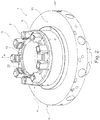
- in perspektivischer Darstellung eine Vorrichtung zur Aufnahme des Werkstücks (ohne dargestelltes Werkstück),
- Fig. 3
- einen Radialschnitt durch die Vorrichtung gemäß
Figur 2 samt Werkstück und einem Teil einer Werkzeugmaschine, in der die Vorrichtung aufgenommen ist, - Fig. 4
- eine vergrößerte Darstellung eines Teils von
Figur 3 , - Fig. 5
- in perspektivischer Darstellung das Aufnahmeunterteil der Vorrichtung gemäß
Figur 2 , - Fig. 6
- die untere Auflagefläche des Aufnahmeoberteils der Vorrichtung gemäß
Figur 2 , mit der das Aufnahmeoberteil auf dem Aufnahmeunterteil aufliegt, und - Fig. 7
- eine schematische Darstellung der Steuerung der Vorrichtung gemäß
Figur 2 . - In
Fig. 1 ist der Bolzenring 2 eines Zykloidengetriebes dargestellt, der mit der im weiteren beschriebenen Vorrichtung gespannt und dann auf einer Werkzeugmaschine feinbearbeitet werden soll. Der Bolzenring 2 hat eine Mittenachse a, die der Achse der im weiteren beschriebenen Vorrichtung entspricht. Hierzu erstreckt sich die radiale Richtung r. - Ziel ist es dabei, die Profilierung 21, die beiden zylindrischen Bohrungsflächen 22 und 23 sowie die Stirnfläche 24 in einer Aufspannung zu bearbeiten, so dass insoweit ein Umspannen des Werkstücks mit damit einhergehenden Genauigkeitsproblemen entbehrlich wird.
- Hierfür kommt eine Vorrichtung 1 zum Einsatz, wie sie in den
Figuren 2 bis 6 vollständig bzw. in Teilen dargestellt ist. - Die Vorrichtung 1 zum Aufnehmen und Spannen des Werkstücks 2 ist auf dem Maschinentisch (Drehtisch) einer Werkzeugmaschine 3 aufgenommen, wie es sich aus
Figur 3 ergibt. Die Vorrichtung 1 hat ein Aufnahmeoberteil 4 und ein Aufnahmeunterteil 5, die zusammen die Vorrichtung 1 bilden. Das Aufnahmeunterteil 5 ist dabei mit dem Maschinentisch der Werkzeugmaschine 3 verbunden, während das Aufnahmeoberteil 4 koaxial zur Mittenachse a mit dem Aufnahmeunterteil 5 lösbar verbunden ist. Zentriermittel 17 (mit zusammenwirkenden Kegelabschnitten) stellen die Zentrierung in radiale Richtung r zwischen Aufnahmeoberteil 4 und Aufnahmeunterteil 5 sicher. - Die Lösbarkeit von Aufnahmeoberteil 4 und Aufnahmeunterteil 5 ermöglicht es, dass das Aufnahmeunterteil 5 in der Werkzeugmaschine 3 montiert bleibt und durch Austauschen des Aufnahmeoberteils 4 eine für ein spezielles Werkstück 2 geeignete Aufnahme auf dem Aufnahmeunterteil 5 montiert wird. Damit wird die Wirtschaftlichkeit der Bearbeitung wesentlich erhöht.
- Zur Zentrierung des Werkstücks 2 bezüglich der Mittenachse a und zum Spannen desselben dienen Betätigungselemente 6, von denen eine Anzahl - im Ausführungsbeispiel neun - um die Mittenachse a herum angeordnet sind. Jedes Betätigungselement 6 arbeitet als autarkes hydraulisches Element, welches in radiale Richtung r eine Anlagekraft auf das Werkstück 2 bzw. einen radialen Verschiebeweg ausüben kann.
- Zur Erzeugung besagter radialer Anlagekraft bzw. des radialen Verschiebewegs werden die Betätigungselemente 6 hydraulisch beaufschlagt, was mittels Aktoren 7 erfolgt, die im Aufnahmeunterteil 5 angeordnet sind. Eine translatorische Verschiebung des Aktors 7 führt zu einer Verdrängung von Hydrauliköl, welches letztlich zu einer Stellbewegung im Betätigungselement 6 führt.
- Hierzu muss allerdings die Verdrängung von hydraulischem Fluid durch den Aktor 7 im Aufnahmeunterteil 5 auf das Aufnahmeoberteil 4 und hier auf die entsprechenden Betätigungselemente 6 übertragen werden.
- Hierfür dienen Übergabeelemente 8, wie sie im Detail in
Figur 4 zu sehen sind. - Ein oberer Abschnitt 9 des Übergabeelements 8 befindet sich im Aufnahmeoberteil 4, während sich ein unterer Abschnitt 10 des Übergabeelements 8 im Aufnahmeunterteil 5 befindet. Jeder Abschnitt 9, 10 weist einen Aufnahmeraum 11 bzw. 12 für hydraulisches Fluid auf. Ferner wird der Aufnahmeraum 11 bzw. 12 jeweils durch ein Übertragungselement 13 bzw. 14 begrenzt. Die beiden Übertragungselemente 13 und 14 liegen dabei aneinander und in der Trendebene 15 zwischen dem Aufnahmeoberteil 4 und dem Aufnahmeunterteil 5 (s.
Figur 4 ). - Durch die Übergabeelemente 8, deren Anzahl derjenigen der Betätigungselemente 6 und der Aktoren 7 entspricht, wird es möglich, die hydraulische Betätigung der Betätigungselemente 6 durch die Aktoren 7 vom Aufnahmeunterteil 5 zum Aufnahmeoberteil 4 zu übertragen, wobei jeweils hermetisch abgeschlossene Teilsysteme vorliegen und somit das hydraulische Fluid sowohl im Aufnahmeunterteil 5 als auch im Aufnahmeoberteil 4 jeweils abgeschlossen ist. Bohrungen im Aufnahmeoberteil 4 und im Aufnahmeunterteil 5, über die das Druckfluid (vom Aktor 7 bis in den Aufnahmeraum 12 bzw. vom Aufnahmeraum 11 bis zum Betätigungselement 6) geführt wird, sind nicht näher dargestellt. Ein hermetischer Abschluss ist insbesondere mit Blick auf das Aufnahmeunterteil allerdings nicht so zu verstehen, dass hier nicht gegebenenfalls ein Nachfülltank für Druckfluid vorhanden sein kann. Mit einem solchen können gegebenenfalls Leckagen des Aktors (d. h. des Verstellkolbens) ausgeglichen werden.
- In jedem Betätigungselement 6 befindet sich ein (nicht dargestellter) Drucksensor, dessen elektrisches Signal vom Aufnahmeoberteil 4 zum Aufnahmeunterteil 5 übertragen werden muss. Hierzu dienen elektrische Kontakte 16, deren Anzahl wiederum derjenigen der Betätigungselemente 6 entspricht.
- Zur Fixierung des Werkstücks 2 im bzw. am Aufnahmeoberteil 4 dienen elektrische Magneten 20, die im Bereich der Auflagefläche 19 für das Werkstück 2 angeordnet sind und somit in der Lage sind, das Werkstück 2 relativ zum Aufnahmeoberteil 4 zu fixieren.
- Im Aufnahmeunterteil 5 sind des weiteren elektronische Controller 18 angeordnet, deren Anzahl wiederum derjenigen der Betätigungselemente 6 entspricht. Die Controller 18 sind nur schematisch angedeutet. In
Figur 7 findet sich eine schematische Darstellung der Steuerung der Vorrichtung 1 unter Einsatz besagter Controller. - Jeder der (im Ausführungsbeispiel: neun) Aktoren 7 (Linearaktoren) besitzt also einen eigenen Controller 18 im Spannfutter, was eine individuelle Positionierung eines einzelnen Aktors 7 durch die SPS (speicherprogrammierbare Steuerung) der Werkzeugmaschine möglich macht.
- Die SPS ist mittels eines Bussystems mit den Controllern 18 verbunden. Es erfolgt die Bestimmung des Drucks in den Betätigungselementen 6 (Spannelementekammern) durch den bereits genannten und nicht dargestellten Drucksensor, der direkt vom zugehörigen Controller 18 erfasst wird.
- Jedem einzelnen Betätigungselement 6 (Spannelement) ist ein elektrischer Magnet 20 zugeordnet. Die Ansteuerung geschieht über einen digitalen Ausgang des Aktor-Controllers.
- Das Anlegen der Betätigungselemente 6 (Spannelemente) an das Werkstück 2 erfolgt druckgesteuert autark durch die SPS in Verbindung mit den Aktor-Controllern.
- Beim Verschiebevorgang erfasst die NC-Steuerung der Werkzeugmaschine die Lage des Werkstücks 2 und berechnet die Verschiebewege der einzelnen Betätigungselemente 6 (Spannelemente). Diese Werte werden an die SPS weitergegeben, die einen Verfahrweg für die einzelnen Aktoren 7 bestimmt und diese entsprechend ansteuert. Als zusätzliche Regelgröße dient zumindest ein in der Werkzeugmaschine stationär montierter Messtaster, der die zu erreichende Endlage des Werkstücks 2 verifiziert.
- Die vorgeschlagene Vorrichtung 1 erlaubt das Bearbeiten der Profilierung 21, der zylindrischen Bohrungsflächen 22 und 23 sowie der Stirnfläche 24 in einer Aufspannung, so dass ein hohes Maß an Präzision erzielt werden kann.
-
- 1
- Vorrichtung
- 2
- Werkstück
- 3
- Werkzeugmaschine (Maschinentisch)
- 4
- Aufnahmeoberteil
- 5
- Aufnahmeunterteil
- 6
- Betätigungselement
- 7
- Aktor
- 8
- Übergabeelement
- 9
- Abschnitt des Übergabeelements
- 10
- Abschnitt des Übergabeelements
- 11
- Aufnahmeraum
- 12
- Aufnahmeraum
- 13
- Übertragungselement (Membran, Kolben)
- 14
- Übertragungselement (Membran, Kolben)
- 15
- Trennebene zwischen Aufnahmeoberteil und Aufnahmeunterteil
- 16
- elektrischer Kontakt
- 17
- Zentriermittel
- 18
- elektronischer Controller
- 19
- Auflagefläche für das Werkstück
- 20
- elektrischer Magnet
- 21
- Profilierung
- 22
- zylindrische Bohrungsfläche
- 23
- zylindrische Bohrungsfläche
- 24
- Stirnfläche
- a
- Mittenachse
- r
- radiale Richtung
Claims (12)
- Vorrichtung (1) zur Aufnahme eines ring- oder scheibenförmigen Werkstücks (2) auf einer Werkzeugmaschine (3), umfassend:ein Aufnahmeoberteil (4), welches zur Aufnahme des Werkstücks (2) ausgebildet ist, und ein Aufnahmeunterteil (5), welches zur Aufnahme in der Werkzeugmaschine (3) ausgebildet ist, wobei das Aufnahmeoberteil (4) und das Aufnahmeunterteil (5) koaxial zu einer Mittenachse (a) lösbar miteinander verbindbar sind,wobei das Aufnahmeoberteil (4) eine Anzahl um die Mittenachse (a) herum angeordnete Betätigungselemente (6) aufweist, mit denen jeweils eine radial (r) wirkende Kraft und/oder eine radiale Verschiebung auf das Werkstück (2) ausgeübt werden kann, wobei die Betätigungselemente (6) durch Verdrängung eines Druckfluids, insbesondere eines Hydrauliköls, betätigt werden,wobei im Aufnahmeunterteil (5) eine der Anzahl der Betätigungselemente (6) entsprechende Anzahl an Aktoren (7) angeordnet ist, mit denen jeweils ein definiertes Volumen an Druckfluid zu jeweils einem Übergabeelement (8) gefördert werden kann, wobei eine der Anzahl der Betätigungselemente (6) entsprechende Anzahl an Übergabeelementen (8) vorhanden ist,wobei jedes Übergabeelement (8) einen im Aufnahmeoberteil (4) angeordneten Abschnitt (9) und einen im Aufnahmeunterteil (5) angeordneten Abschnitt (10) aufweist, wobei jeder Abschnitt (9, 10) jeweils einen Aufnahmeraum (11, 12) für Druckfluid aufweist, der von je einem Übertragungselement (13, 14) begrenzt wird, mit dem eine infolge der Verdrängung von Druckfluid bedingte Bewegung eines der Übertragungselemente (14) auf das andere Übertragungselement (13) übertragen kann, undwobei die Übertragungselemente (13, 14) bei verbundenem Aufnahmeoberteil (4) und Aufnahmeunterteil (5) an einer Fläche aneinander liegen, die der Trennebene (15) zwischen Aufnahmeoberteil (4) und Aufnahmeunterteil (5) entspricht.
- Vorrichtung nach Anspruch 1, dadurch gekennzeichnet, dass die Übertragungselemente (13, 14) als elastische Membranen ausgebildet sind, wobei die Membranen vorzugsweise aus einem elastomeren Material oder aus Metall bestehen.
- Vorrichtung nach Anspruch 1, dadurch gekennzeichnet, dass die Übertragungselemente (13, 14) als Kolben ausgebildet sind, die im Aufnahmeraum (11, 12) verschieblich angeordnet sind, wobei die Kolben vorzugsweise aus keramischem Material bestehen.
- Vorrichtung nach einem der Ansprüche 1 bis 3, dadurch gekennzeichnet, dass im Aufnahmeoberteil (4) zwischen 3 und 12 Betätigungselemente (6) um die Mittenachse (a) herum angeordnet sind, vorzugsweise zwischen 6 und 9 Betätigungselemente (6), wobei die Betätigungselemente (6) vorzugsweise äquidistant um die Mittenachse (a) herum angeordnet sind.
- Vorrichtung nach einem der Ansprüche 1 bis 4, dadurch gekennzeichnet, dass eine der Anzahl der Betätigungselemente (6) entsprechende Anzahl an lösbaren elektrischen Kontakten (16) angeordnet sind, wobei ein Teil des elektrischen Kontakts im Aufnahmeoberteil (4) und ein Teil des elektrischen Kontakts im Aufnahmeunterteil (5) angeordnet ist.
- Vorrichtung nach Anspruch 5, dadurch gekennzeichnet, dass in jedem Betätigungselement (6) ein Drucksensor angeordnet ist, wobei ein dem Druck entsprechendes elektrisches Signal des Drucksensors über den elektrischen Kontakt (16) vom Aufnahmeoberteil (4) zum Aufnahmeunterteil (5) übertragen werden kann.
- Vorrichtung nach einem der Ansprüche 1 bis 6, dadurch gekennzeichnet, dass Zentriermittel (17) angeordnet sind, mit dem das Aufnahmeoberteil (4) relativ zum Aufnahmeunterteil (5) zentriert werden kann.
- Vorrichtung nach einem der Ansprüche 1 bis 7, dadurch gekennzeichnet, dass jedem Aktor (7) ein im Aufnahmeunterteil (5) angeordneter elektronischer Controller (18) zugeordnet ist.
- Vorrichtung nach einem der Ansprüche 1 bis 8, dadurch gekennzeichnet, dass das Aufnahmeoberteil (4) eine Auflagefläche (19) für das Werkstück (2) aufweist, wobei im Bereich der Auflagefläche (19) mindestens ein elektrischer Magnet (20) angeordnet ist, mit dem das Werkstück (2) auf oder an dem Aufnahmeoberteil (4) fixiert werden kann.
- Vorrichtung nach Anspruch 9, dadurch gekennzeichnet, dass jedem Betätigungselement (6) ein elektrischer Magnet (20) zugeordnet ist.
- Vorrichtung nach einem der Ansprüche 1 bis 10, dadurch gekennzeichnet, dass sie auf einem Drehtisch der Werkzeugmaschine (3) angeordnet ist, um um die Mittenachse (a) rotieren zu können.
- Vorrichtung nach einem der Ansprüche 1 bis 11, dadurch gekennzeichnet, dass die Betätigungselemente (6) im Aufnahmeoberteil (4) lösbar befestigt sind.
Applications Claiming Priority (1)
| Application Number | Priority Date | Filing Date | Title |
|---|---|---|---|
| DE102017007527.1A DE102017007527A1 (de) | 2017-08-10 | 2017-08-10 | Vorrichtung zur Aufnahme eines ring- oder scheibenförmigen Werkstücks auf einer Werkzeugmaschine |
Publications (2)
| Publication Number | Publication Date |
|---|---|
| EP3444066A1 EP3444066A1 (de) | 2019-02-20 |
| EP3444066B1 true EP3444066B1 (de) | 2020-06-17 |
Family
ID=63168288
Family Applications (1)
| Application Number | Title | Priority Date | Filing Date |
|---|---|---|---|
| EP18187626.9A Active EP3444066B1 (de) | 2017-08-10 | 2018-08-07 | Vorrichtung zur aufnahme eines ring- oder scheibenförmigen werkstücks auf einer werkzeugmaschine |
Country Status (4)
| Country | Link |
|---|---|
| EP (1) | EP3444066B1 (de) |
| JP (1) | JP7201361B2 (de) |
| CN (1) | CN109382690B (de) |
| DE (1) | DE102017007527A1 (de) |
Cited By (1)
| Publication number | Priority date | Publication date | Assignee | Title |
|---|---|---|---|---|
| EP4070915A1 (de) * | 2021-04-06 | 2022-10-12 | Agathon AG, Maschinenfabrik | Werkstückhalter und verfahren zur herstellung eines rotationssymmetrischen werkzeugs |
Families Citing this family (2)
| Publication number | Priority date | Publication date | Assignee | Title |
|---|---|---|---|---|
| CN110561142A (zh) * | 2019-04-11 | 2019-12-13 | 齐齐哈尔雷昂重工机械制造有限责任公司 | 一种工作台自动定心卡紧机构 |
| CN112008447B (zh) * | 2020-09-07 | 2022-05-06 | 镇江丹风气动工具有限公司 | 一种铣夹头三槽用夹具工装及其安装使用方法 |
Family Cites Families (15)
| Publication number | Priority date | Publication date | Assignee | Title |
|---|---|---|---|---|
| DE645770C (de) * | 1934-01-06 | 1937-06-02 | Waldemar Sonsalla | Loesbare Verbindung fuer Anschlussleitungen von Manometern |
| DE1048108B (de) * | 1952-02-05 | 1958-12-31 | Alltools Ltd | Kupplung fuer Leitungen zur hydrostatischen Druckuebertragung |
| JPS63251106A (ja) * | 1987-04-01 | 1988-10-18 | Miyano:Kk | チヤツク装置 |
| JPH1086004A (ja) * | 1996-09-18 | 1998-04-07 | Howa Mach Ltd | 流体供給装置 |
| JP3825119B2 (ja) * | 1997-03-06 | 2006-09-20 | 帝国チャック株式会社 | 薄肉・脆性ワーク用チャック装置 |
| DE10117485B4 (de) * | 2001-04-07 | 2004-12-02 | Schunk Gmbh & Co. Kg Fabrik Für Spann- Und Greifwerkzeuge | Spanneinrichtung |
| JP2004291196A (ja) * | 2003-03-28 | 2004-10-21 | Olympus Corp | チャック |
| DE202006015097U1 (de) * | 2006-10-02 | 2006-11-23 | Deckel Maho Pfronten Gmbh | Hydraulische Spannvorrichtung zum Innen- und Außenspannen von Werkstücken |
| US7654178B2 (en) * | 2007-01-02 | 2010-02-02 | Hall David R | Hydraulic chuck with independently moveable jaws |
| CN201446428U (zh) * | 2009-05-29 | 2010-05-05 | 许家地 | 立式车床汽车钢圈轮幅专用夹具 |
| DE202009013226U1 (de) * | 2009-09-22 | 2009-12-17 | SAV Spann-, Automations-, Normteiletechnik GmbH | Spannfutter zum Spannen und Zentrieren ringförmig ausgebildeter und verformungsempfindlicher Werkstücke |
| CN201579636U (zh) * | 2009-12-31 | 2010-09-15 | 沈阳锦德机械有限公司 | 一种立式车床悬浮卡爪 |
| CN103567862B (zh) * | 2012-07-23 | 2016-03-09 | 沈阳海默数控机床有限公司 | 盘类零件磨削专用薄膜卡盘 |
| JP6191292B2 (ja) * | 2013-07-10 | 2017-09-06 | Smc株式会社 | 工作機械用チャック装置及び工作機械のチャック方法 |
| CN203853841U (zh) * | 2014-05-29 | 2014-10-01 | 浙江利帆家具有限公司 | 一种新型机床夹具 |
-
2017
- 2017-08-10 DE DE102017007527.1A patent/DE102017007527A1/de not_active Withdrawn
-
2018
- 2018-08-07 EP EP18187626.9A patent/EP3444066B1/de active Active
- 2018-08-08 JP JP2018149759A patent/JP7201361B2/ja active Active
- 2018-08-09 CN CN201810904127.4A patent/CN109382690B/zh not_active Expired - Fee Related
Non-Patent Citations (1)
| Title |
|---|
| None * |
Cited By (1)
| Publication number | Priority date | Publication date | Assignee | Title |
|---|---|---|---|---|
| EP4070915A1 (de) * | 2021-04-06 | 2022-10-12 | Agathon AG, Maschinenfabrik | Werkstückhalter und verfahren zur herstellung eines rotationssymmetrischen werkzeugs |
Also Published As
| Publication number | Publication date |
|---|---|
| CN109382690B (zh) | 2021-12-21 |
| JP7201361B2 (ja) | 2023-01-10 |
| JP2019034406A (ja) | 2019-03-07 |
| DE102017007527A1 (de) | 2019-02-14 |
| EP3444066A1 (de) | 2019-02-20 |
| CN109382690A (zh) | 2019-02-26 |
Similar Documents
| Publication | Publication Date | Title |
|---|---|---|
| EP0305735B1 (de) | Werkzeugmaschine zur Bearbeitung von Werkstücken mittels rundlaufender Werkzeuge | |
| EP2383058B1 (de) | Kraftbetätigtes Spannfutter | |
| EP3050661B1 (de) | Verzahnungs- oder profilschleifmaschine und verfahren zum betreiben einer solchen | |
| EP2275217B1 (de) | Vorrichtung zum Einspannen eines Werkstücks | |
| DE102019133760B4 (de) | Modulares Spannsystem und Verfahren | |
| EP2559507A1 (de) | Manuell betätigbares Spannfutter | |
| DE4315839C2 (de) | Werkstückspannvorrichtung für Mehrseitenbearbeitung | |
| EP4021680B1 (de) | Ecm-anlage mit einer aufnahme und einer bearbeitungsplattform | |
| EP3444066A1 (de) | Vorrichtung zur aufnahme eines ring- oder scheibenförmigen werkstücks auf einer werkzeugmaschine | |
| EP3338941B1 (de) | Rundtaktmaschine | |
| EP0316552B1 (de) | Vorrichtung zum Einbringen von Befestigungsbohrungen oder Ventilbohrungen in eine Schüssel bzw. eine Felge eines Rades eines Kraftfahrzeuges | |
| EP2001625A1 (de) | Spannvorrichtung für rotierende werkzeuge oder werkstücke | |
| DE102017121031A1 (de) | Werkzeug zur Durchführung eines Presshärt- und Abschreckverfahrens | |
| EP0088212A1 (de) | Numerische Steuerung für Bearbeitungsmaschinen | |
| DD143698A3 (de) | Transportables drehgeraet fuer flanschdichtflaechen | |
| EP3774141B1 (de) | Hydrodehnspannwerkzeug und dessen verwendung | |
| EP3611584B1 (de) | Verfahren zum betrieb einer drehmaschine mit einer lünette | |
| DE102010000579B4 (de) | Werkstückaufnahme zur Halterung eines in einer Werkzeugmaschine zu bearbeitendes Werkstücks | |
| EP3645260B1 (de) | Ebenenplatte eines pressenwerkzeugs | |
| EP0753379B1 (de) | Bearbeitungsstation für eine spanabhebende Bearbeitung eines Werkstückes | |
| EP2623257A1 (de) | Positionsausgleichsvorrichtung in einer Werkzeugmaschine | |
| EP2279828B1 (de) | Aufspanneinrichtung und Bearbeitungseinrichtung | |
| DE102015016363A1 (de) | Spannvorrichtung für eine Schweißanlage | |
| DE1183761B (de) | Schrittschaltwerk zum Verschieben eines stangenfoermigen Schaltstueckes in kleinen Schritten | |
| DE19705688C2 (de) | Bearbeitungspalette für die spanabhebende Bearbeitung |
Legal Events
| Date | Code | Title | Description |
|---|---|---|---|
| PUAI | Public reference made under article 153(3) epc to a published international application that has entered the european phase |
Free format text: ORIGINAL CODE: 0009012 |
|
| STAA | Information on the status of an ep patent application or granted ep patent |
Free format text: STATUS: THE APPLICATION HAS BEEN PUBLISHED |
|
| AK | Designated contracting states |
Kind code of ref document: A1 Designated state(s): AL AT BE BG CH CY CZ DE DK EE ES FI FR GB GR HR HU IE IS IT LI LT LU LV MC MK MT NL NO PL PT RO RS SE SI SK SM TR |
|
| AX | Request for extension of the european patent |
Extension state: BA ME |
|
| STAA | Information on the status of an ep patent application or granted ep patent |
Free format text: STATUS: REQUEST FOR EXAMINATION WAS MADE |
|
| 17P | Request for examination filed |
Effective date: 20190820 |
|
| RBV | Designated contracting states (corrected) |
Designated state(s): AL AT BE BG CH CY CZ DE DK EE ES FI FR GB GR HR HU IE IS IT LI LT LU LV MC MK MT NL NO PL PT RO RS SE SI SK SM TR |
|
| REG | Reference to a national code |
Ref country code: DE Ref legal event code: R079 Ref document number: 502018001681 Country of ref document: DE Free format text: PREVIOUS MAIN CLASS: B23Q0001000000 Ipc: B23B0031300000 |
|
| GRAP | Despatch of communication of intention to grant a patent |
Free format text: ORIGINAL CODE: EPIDOSNIGR1 |
|
| STAA | Information on the status of an ep patent application or granted ep patent |
Free format text: STATUS: GRANT OF PATENT IS INTENDED |
|
| RIC1 | Information provided on ipc code assigned before grant |
Ipc: B23B 31/30 20060101AFI20200206BHEP |
|
| INTG | Intention to grant announced |
Effective date: 20200306 |
|
| GRAS | Grant fee paid |
Free format text: ORIGINAL CODE: EPIDOSNIGR3 |
|
| GRAA | (expected) grant |
Free format text: ORIGINAL CODE: 0009210 |
|
| STAA | Information on the status of an ep patent application or granted ep patent |
Free format text: STATUS: THE PATENT HAS BEEN GRANTED |
|
| AK | Designated contracting states |
Kind code of ref document: B1 Designated state(s): AL AT BE BG CH CY CZ DE DK EE ES FI FR GB GR HR HU IE IS IT LI LT LU LV MC MK MT NL NO PL PT RO RS SE SI SK SM TR |
|
| REG | Reference to a national code |
Ref country code: GB Ref legal event code: FG4D Free format text: NOT ENGLISH |
|
| REG | Reference to a national code |
Ref country code: CH Ref legal event code: EP |
|
| REG | Reference to a national code |
Ref country code: IE Ref legal event code: FG4D Free format text: LANGUAGE OF EP DOCUMENT: GERMAN |
|
| REG | Reference to a national code |
Ref country code: DE Ref legal event code: R096 Ref document number: 502018001681 Country of ref document: DE |
|
| REG | Reference to a national code |
Ref country code: AT Ref legal event code: REF Ref document number: 1280715 Country of ref document: AT Kind code of ref document: T Effective date: 20200715 |
|
| PG25 | Lapsed in a contracting state [announced via postgrant information from national office to epo] |
Ref country code: NO Free format text: LAPSE BECAUSE OF FAILURE TO SUBMIT A TRANSLATION OF THE DESCRIPTION OR TO PAY THE FEE WITHIN THE PRESCRIBED TIME-LIMIT Effective date: 20200917 Ref country code: FI Free format text: LAPSE BECAUSE OF FAILURE TO SUBMIT A TRANSLATION OF THE DESCRIPTION OR TO PAY THE FEE WITHIN THE PRESCRIBED TIME-LIMIT Effective date: 20200617 Ref country code: GR Free format text: LAPSE BECAUSE OF FAILURE TO SUBMIT A TRANSLATION OF THE DESCRIPTION OR TO PAY THE FEE WITHIN THE PRESCRIBED TIME-LIMIT Effective date: 20200918 Ref country code: LT Free format text: LAPSE BECAUSE OF FAILURE TO SUBMIT A TRANSLATION OF THE DESCRIPTION OR TO PAY THE FEE WITHIN THE PRESCRIBED TIME-LIMIT Effective date: 20200617 Ref country code: SE Free format text: LAPSE BECAUSE OF FAILURE TO SUBMIT A TRANSLATION OF THE DESCRIPTION OR TO PAY THE FEE WITHIN THE PRESCRIBED TIME-LIMIT Effective date: 20200617 |
|
| REG | Reference to a national code |
Ref country code: LT Ref legal event code: MG4D |
|
| REG | Reference to a national code |
Ref country code: NL Ref legal event code: MP Effective date: 20200617 |
|
| PG25 | Lapsed in a contracting state [announced via postgrant information from national office to epo] |
Ref country code: RS Free format text: LAPSE BECAUSE OF FAILURE TO SUBMIT A TRANSLATION OF THE DESCRIPTION OR TO PAY THE FEE WITHIN THE PRESCRIBED TIME-LIMIT Effective date: 20200617 Ref country code: HR Free format text: LAPSE BECAUSE OF FAILURE TO SUBMIT A TRANSLATION OF THE DESCRIPTION OR TO PAY THE FEE WITHIN THE PRESCRIBED TIME-LIMIT Effective date: 20200617 Ref country code: BG Free format text: LAPSE BECAUSE OF FAILURE TO SUBMIT A TRANSLATION OF THE DESCRIPTION OR TO PAY THE FEE WITHIN THE PRESCRIBED TIME-LIMIT Effective date: 20200917 Ref country code: LV Free format text: LAPSE BECAUSE OF FAILURE TO SUBMIT A TRANSLATION OF THE DESCRIPTION OR TO PAY THE FEE WITHIN THE PRESCRIBED TIME-LIMIT Effective date: 20200617 |
|
| PG25 | Lapsed in a contracting state [announced via postgrant information from national office to epo] |
Ref country code: NL Free format text: LAPSE BECAUSE OF FAILURE TO SUBMIT A TRANSLATION OF THE DESCRIPTION OR TO PAY THE FEE WITHIN THE PRESCRIBED TIME-LIMIT Effective date: 20200617 Ref country code: AL Free format text: LAPSE BECAUSE OF FAILURE TO SUBMIT A TRANSLATION OF THE DESCRIPTION OR TO PAY THE FEE WITHIN THE PRESCRIBED TIME-LIMIT Effective date: 20200617 |
|
| PG25 | Lapsed in a contracting state [announced via postgrant information from national office to epo] |
Ref country code: ES Free format text: LAPSE BECAUSE OF FAILURE TO SUBMIT A TRANSLATION OF THE DESCRIPTION OR TO PAY THE FEE WITHIN THE PRESCRIBED TIME-LIMIT Effective date: 20200617 Ref country code: PT Free format text: LAPSE BECAUSE OF FAILURE TO SUBMIT A TRANSLATION OF THE DESCRIPTION OR TO PAY THE FEE WITHIN THE PRESCRIBED TIME-LIMIT Effective date: 20201019 Ref country code: RO Free format text: LAPSE BECAUSE OF FAILURE TO SUBMIT A TRANSLATION OF THE DESCRIPTION OR TO PAY THE FEE WITHIN THE PRESCRIBED TIME-LIMIT Effective date: 20200617 Ref country code: CZ Free format text: LAPSE BECAUSE OF FAILURE TO SUBMIT A TRANSLATION OF THE DESCRIPTION OR TO PAY THE FEE WITHIN THE PRESCRIBED TIME-LIMIT Effective date: 20200617 Ref country code: EE Free format text: LAPSE BECAUSE OF FAILURE TO SUBMIT A TRANSLATION OF THE DESCRIPTION OR TO PAY THE FEE WITHIN THE PRESCRIBED TIME-LIMIT Effective date: 20200617 Ref country code: IT Free format text: LAPSE BECAUSE OF FAILURE TO SUBMIT A TRANSLATION OF THE DESCRIPTION OR TO PAY THE FEE WITHIN THE PRESCRIBED TIME-LIMIT Effective date: 20200617 Ref country code: SM Free format text: LAPSE BECAUSE OF FAILURE TO SUBMIT A TRANSLATION OF THE DESCRIPTION OR TO PAY THE FEE WITHIN THE PRESCRIBED TIME-LIMIT Effective date: 20200617 |
|
| PG25 | Lapsed in a contracting state [announced via postgrant information from national office to epo] |
Ref country code: PL Free format text: LAPSE BECAUSE OF FAILURE TO SUBMIT A TRANSLATION OF THE DESCRIPTION OR TO PAY THE FEE WITHIN THE PRESCRIBED TIME-LIMIT Effective date: 20200617 Ref country code: SK Free format text: LAPSE BECAUSE OF FAILURE TO SUBMIT A TRANSLATION OF THE DESCRIPTION OR TO PAY THE FEE WITHIN THE PRESCRIBED TIME-LIMIT Effective date: 20200617 Ref country code: IS Free format text: LAPSE BECAUSE OF FAILURE TO SUBMIT A TRANSLATION OF THE DESCRIPTION OR TO PAY THE FEE WITHIN THE PRESCRIBED TIME-LIMIT Effective date: 20201017 |
|
| REG | Reference to a national code |
Ref country code: DE Ref legal event code: R097 Ref document number: 502018001681 Country of ref document: DE |
|
| PG25 | Lapsed in a contracting state [announced via postgrant information from national office to epo] |
Ref country code: MC Free format text: LAPSE BECAUSE OF FAILURE TO SUBMIT A TRANSLATION OF THE DESCRIPTION OR TO PAY THE FEE WITHIN THE PRESCRIBED TIME-LIMIT Effective date: 20200617 |
|
| PLBE | No opposition filed within time limit |
Free format text: ORIGINAL CODE: 0009261 |
|
| STAA | Information on the status of an ep patent application or granted ep patent |
Free format text: STATUS: NO OPPOSITION FILED WITHIN TIME LIMIT |
|
| PG25 | Lapsed in a contracting state [announced via postgrant information from national office to epo] |
Ref country code: LU Free format text: LAPSE BECAUSE OF NON-PAYMENT OF DUE FEES Effective date: 20200807 Ref country code: DK Free format text: LAPSE BECAUSE OF FAILURE TO SUBMIT A TRANSLATION OF THE DESCRIPTION OR TO PAY THE FEE WITHIN THE PRESCRIBED TIME-LIMIT Effective date: 20200617 |
|
| 26N | No opposition filed |
Effective date: 20210318 |
|
| REG | Reference to a national code |
Ref country code: BE Ref legal event code: MM Effective date: 20200831 |
|
| PG25 | Lapsed in a contracting state [announced via postgrant information from national office to epo] |
Ref country code: SI Free format text: LAPSE BECAUSE OF FAILURE TO SUBMIT A TRANSLATION OF THE DESCRIPTION OR TO PAY THE FEE WITHIN THE PRESCRIBED TIME-LIMIT Effective date: 20200617 |
|
| PG25 | Lapsed in a contracting state [announced via postgrant information from national office to epo] |
Ref country code: FR Free format text: LAPSE BECAUSE OF NON-PAYMENT OF DUE FEES Effective date: 20200817 |
|
| PG25 | Lapsed in a contracting state [announced via postgrant information from national office to epo] |
Ref country code: BE Free format text: LAPSE BECAUSE OF NON-PAYMENT OF DUE FEES Effective date: 20200831 Ref country code: IE Free format text: LAPSE BECAUSE OF NON-PAYMENT OF DUE FEES Effective date: 20200807 |
|
| PG25 | Lapsed in a contracting state [announced via postgrant information from national office to epo] |
Ref country code: TR Free format text: LAPSE BECAUSE OF FAILURE TO SUBMIT A TRANSLATION OF THE DESCRIPTION OR TO PAY THE FEE WITHIN THE PRESCRIBED TIME-LIMIT Effective date: 20200617 Ref country code: MT Free format text: LAPSE BECAUSE OF FAILURE TO SUBMIT A TRANSLATION OF THE DESCRIPTION OR TO PAY THE FEE WITHIN THE PRESCRIBED TIME-LIMIT Effective date: 20200617 Ref country code: CY Free format text: LAPSE BECAUSE OF FAILURE TO SUBMIT A TRANSLATION OF THE DESCRIPTION OR TO PAY THE FEE WITHIN THE PRESCRIBED TIME-LIMIT Effective date: 20200617 |
|
| PG25 | Lapsed in a contracting state [announced via postgrant information from national office to epo] |
Ref country code: MK Free format text: LAPSE BECAUSE OF FAILURE TO SUBMIT A TRANSLATION OF THE DESCRIPTION OR TO PAY THE FEE WITHIN THE PRESCRIBED TIME-LIMIT Effective date: 20200617 |
|
| GBPC | Gb: european patent ceased through non-payment of renewal fee |
Effective date: 20220807 |
|
| PG25 | Lapsed in a contracting state [announced via postgrant information from national office to epo] |
Ref country code: GB Free format text: LAPSE BECAUSE OF NON-PAYMENT OF DUE FEES Effective date: 20220807 |
|
| REG | Reference to a national code |
Ref country code: AT Ref legal event code: MM01 Ref document number: 1280715 Country of ref document: AT Kind code of ref document: T Effective date: 20230807 |
|
| PG25 | Lapsed in a contracting state [announced via postgrant information from national office to epo] |
Ref country code: AT Free format text: LAPSE BECAUSE OF NON-PAYMENT OF DUE FEES Effective date: 20230807 |
|
| PG25 | Lapsed in a contracting state [announced via postgrant information from national office to epo] |
Ref country code: AT Free format text: LAPSE BECAUSE OF NON-PAYMENT OF DUE FEES Effective date: 20230807 |
|
| PGFP | Annual fee paid to national office [announced via postgrant information from national office to epo] |
Ref country code: DE Payment date: 20250819 Year of fee payment: 8 |
|
| PGFP | Annual fee paid to national office [announced via postgrant information from national office to epo] |
Ref country code: CH Payment date: 20250901 Year of fee payment: 8 |
|
| PGFP | Annual fee paid to national office [announced via postgrant information from national office to epo] |
Ref country code: AT Payment date: 20260410 Year of fee payment: 5 |