EP3443445B1 - Verbundglasscheibe mit einer sensoranordnung, übertragungssystem und verfahren zur herstellung einer verbundglasscheibe mit einer sensoranordnung - Google Patents
Verbundglasscheibe mit einer sensoranordnung, übertragungssystem und verfahren zur herstellung einer verbundglasscheibe mit einer sensoranordnung Download PDFInfo
- Publication number
- EP3443445B1 EP3443445B1 EP17707560.3A EP17707560A EP3443445B1 EP 3443445 B1 EP3443445 B1 EP 3443445B1 EP 17707560 A EP17707560 A EP 17707560A EP 3443445 B1 EP3443445 B1 EP 3443445B1
- Authority
- EP
- European Patent Office
- Prior art keywords
- ant
- sensor
- laminated glass
- glass pane
- antenna
- Prior art date
- Legal status (The legal status is an assumption and is not a legal conclusion. Google has not performed a legal analysis and makes no representation as to the accuracy of the status listed.)
- Active
Links
Images



Classifications
-
- B—PERFORMING OPERATIONS; TRANSPORTING
- B32—LAYERED PRODUCTS
- B32B—LAYERED PRODUCTS, i.e. PRODUCTS BUILT-UP OF STRATA OF FLAT OR NON-FLAT, e.g. CELLULAR OR HONEYCOMB, FORM
- B32B17/00—Layered products essentially comprising sheet glass, or glass, slag, or like fibres
- B32B17/06—Layered products essentially comprising sheet glass, or glass, slag, or like fibres comprising glass as the main or only constituent of a layer, next to another layer of a specific material
- B32B17/10—Layered products essentially comprising sheet glass, or glass, slag, or like fibres comprising glass as the main or only constituent of a layer, next to another layer of a specific material of synthetic resin
- B32B17/10005—Layered products essentially comprising sheet glass, or glass, slag, or like fibres comprising glass as the main or only constituent of a layer, next to another layer of a specific material of synthetic resin laminated safety glass or glazing
- B32B17/10165—Functional features of the laminated safety glass or glazing
-
- G—PHYSICS
- G06—COMPUTING OR CALCULATING; COUNTING
- G06F—ELECTRIC DIGITAL DATA PROCESSING
- G06F3/00—Input arrangements for transferring data to be processed into a form capable of being handled by the computer; Output arrangements for transferring data from processing unit to output unit, e.g. interface arrangements
- G06F3/01—Input arrangements or combined input and output arrangements for interaction between user and computer
- G06F3/03—Arrangements for converting the position or the displacement of a member into a coded form
- G06F3/041—Digitisers, e.g. for touch screens or touch pads, characterised by the transducing means
-
- B—PERFORMING OPERATIONS; TRANSPORTING
- B32—LAYERED PRODUCTS
- B32B—LAYERED PRODUCTS, i.e. PRODUCTS BUILT-UP OF STRATA OF FLAT OR NON-FLAT, e.g. CELLULAR OR HONEYCOMB, FORM
- B32B17/00—Layered products essentially comprising sheet glass, or glass, slag, or like fibres
- B32B17/06—Layered products essentially comprising sheet glass, or glass, slag, or like fibres comprising glass as the main or only constituent of a layer, next to another layer of a specific material
- B32B17/10—Layered products essentially comprising sheet glass, or glass, slag, or like fibres comprising glass as the main or only constituent of a layer, next to another layer of a specific material of synthetic resin
- B32B17/10005—Layered products essentially comprising sheet glass, or glass, slag, or like fibres comprising glass as the main or only constituent of a layer, next to another layer of a specific material of synthetic resin laminated safety glass or glazing
- B32B17/10009—Layered products essentially comprising sheet glass, or glass, slag, or like fibres comprising glass as the main or only constituent of a layer, next to another layer of a specific material of synthetic resin laminated safety glass or glazing characterized by the number, the constitution or treatment of glass sheets
- B32B17/10036—Layered products essentially comprising sheet glass, or glass, slag, or like fibres comprising glass as the main or only constituent of a layer, next to another layer of a specific material of synthetic resin laminated safety glass or glazing characterized by the number, the constitution or treatment of glass sheets comprising two outer glass sheets
-
- B—PERFORMING OPERATIONS; TRANSPORTING
- B32—LAYERED PRODUCTS
- B32B—LAYERED PRODUCTS, i.e. PRODUCTS BUILT-UP OF STRATA OF FLAT OR NON-FLAT, e.g. CELLULAR OR HONEYCOMB, FORM
- B32B17/00—Layered products essentially comprising sheet glass, or glass, slag, or like fibres
- B32B17/06—Layered products essentially comprising sheet glass, or glass, slag, or like fibres comprising glass as the main or only constituent of a layer, next to another layer of a specific material
- B32B17/10—Layered products essentially comprising sheet glass, or glass, slag, or like fibres comprising glass as the main or only constituent of a layer, next to another layer of a specific material of synthetic resin
- B32B17/10005—Layered products essentially comprising sheet glass, or glass, slag, or like fibres comprising glass as the main or only constituent of a layer, next to another layer of a specific material of synthetic resin laminated safety glass or glazing
- B32B17/10165—Functional features of the laminated safety glass or glazing
- B32B17/10174—Coatings of a metallic or dielectric material on a constituent layer of glass or polymer
-
- B—PERFORMING OPERATIONS; TRANSPORTING
- B60—VEHICLES IN GENERAL
- B60J—WINDOWS, WINDSCREENS, NON-FIXED ROOFS, DOORS, OR SIMILAR DEVICES FOR VEHICLES; REMOVABLE EXTERNAL PROTECTIVE COVERINGS SPECIALLY ADAPTED FOR VEHICLES
- B60J1/00—Windows; Windscreens; Accessories therefor
- B60J1/02—Windows; Windscreens; Accessories therefor arranged at the vehicle front, e.g. structure of the glazing, mounting of the glazing
-
- B—PERFORMING OPERATIONS; TRANSPORTING
- B60—VEHICLES IN GENERAL
- B60J—WINDOWS, WINDSCREENS, NON-FIXED ROOFS, DOORS, OR SIMILAR DEVICES FOR VEHICLES; REMOVABLE EXTERNAL PROTECTIVE COVERINGS SPECIALLY ADAPTED FOR VEHICLES
- B60J1/00—Windows; Windscreens; Accessories therefor
- B60J1/20—Accessories, e.g. wind deflectors, blinds
-
- B—PERFORMING OPERATIONS; TRANSPORTING
- B60—VEHICLES IN GENERAL
- B60S—SERVICING, CLEANING, REPAIRING, SUPPORTING, LIFTING, OR MANOEUVRING OF VEHICLES, NOT OTHERWISE PROVIDED FOR
- B60S1/00—Cleaning of vehicles
- B60S1/02—Cleaning windscreens, windows or optical devices
- B60S1/04—Wipers or the like, e.g. scrapers
- B60S1/06—Wipers or the like, e.g. scrapers characterised by the drive
- B60S1/08—Wipers or the like, e.g. scrapers characterised by the drive electrically driven
- B60S1/0818—Wipers or the like, e.g. scrapers characterised by the drive electrically driven including control systems responsive to external conditions, e.g. by detection of moisture, dirt or the like
- B60S1/0822—Wipers or the like, e.g. scrapers characterised by the drive electrically driven including control systems responsive to external conditions, e.g. by detection of moisture, dirt or the like characterized by the arrangement or type of detection means
- B60S1/0874—Wipers or the like, e.g. scrapers characterised by the drive electrically driven including control systems responsive to external conditions, e.g. by detection of moisture, dirt or the like characterized by the arrangement or type of detection means characterized by the position of the sensor on the windshield
- B60S1/0877—Wipers or the like, e.g. scrapers characterised by the drive electrically driven including control systems responsive to external conditions, e.g. by detection of moisture, dirt or the like characterized by the arrangement or type of detection means characterized by the position of the sensor on the windshield at least part of the sensor being positioned between layers of the windshield
-
- E—FIXED CONSTRUCTIONS
- E06—DOORS, WINDOWS, SHUTTERS, OR ROLLER BLINDS IN GENERAL; LADDERS
- E06B—FIXED OR MOVABLE CLOSURES FOR OPENINGS IN BUILDINGS, VEHICLES, FENCES OR LIKE ENCLOSURES IN GENERAL, e.g. DOORS, WINDOWS, BLINDS, GATES
- E06B7/00—Special arrangements or measures in connection with doors or windows
- E06B7/28—Other arrangements on doors or windows, e.g. door-plates, windows adapted to carry plants, hooks for window cleaners
-
- H—ELECTRICITY
- H01—ELECTRIC ELEMENTS
- H01Q—ANTENNAS, i.e. RADIO AERIALS
- H01Q1/00—Details of, or arrangements associated with, antennas
- H01Q1/12—Supports; Mounting means
- H01Q1/1271—Supports; Mounting means for mounting on windscreens
-
- B—PERFORMING OPERATIONS; TRANSPORTING
- B32—LAYERED PRODUCTS
- B32B—LAYERED PRODUCTS, i.e. PRODUCTS BUILT-UP OF STRATA OF FLAT OR NON-FLAT, e.g. CELLULAR OR HONEYCOMB, FORM
- B32B2605/00—Vehicles
-
- B—PERFORMING OPERATIONS; TRANSPORTING
- B32—LAYERED PRODUCTS
- B32B—LAYERED PRODUCTS, i.e. PRODUCTS BUILT-UP OF STRATA OF FLAT OR NON-FLAT, e.g. CELLULAR OR HONEYCOMB, FORM
- B32B2605/00—Vehicles
- B32B2605/006—Transparent parts other than made from inorganic glass, e.g. polycarbonate glazings
-
- G—PHYSICS
- G06—COMPUTING OR CALCULATING; COUNTING
- G06F—ELECTRIC DIGITAL DATA PROCESSING
- G06F3/00—Input arrangements for transferring data to be processed into a form capable of being handled by the computer; Output arrangements for transferring data from processing unit to output unit, e.g. interface arrangements
- G06F3/01—Input arrangements or combined input and output arrangements for interaction between user and computer
- G06F3/03—Arrangements for converting the position or the displacement of a member into a coded form
- G06F3/041—Digitisers, e.g. for touch screens or touch pads, characterised by the transducing means
- G06F3/044—Digitisers, e.g. for touch screens or touch pads, characterised by the transducing means by capacitive means
Definitions
- the invention relates to a laminated glass pane with a sensor arrangement, a transmission system and a method for producing the laminated glass pane with a sensor arrangement.
- Laminated glass panes are used in many places today, particularly in vehicle construction.
- vehicle is broadly defined and relates to road vehicles, aircraft, ships, agricultural machinery or work equipment, among other things.
- Laminated glass panes are also used in other areas. These include, for example, building glazing and information displays, e.g. in museums or as advertising displays.
- a laminated glass pane generally has two glass surfaces which are laminated to an intermediate layer. The glass surfaces themselves can have a curvature and are usually of constant thickness.
- the intermediate layer typically comprises a thermoplastic material, typically polyvinyl butyral (PVB), of a predetermined thickness, e.g., 0.76 mm.
- PVB polyvinyl butyral
- sensors of different types There is often a desire to attach sensors of different types. Previous sensors were housed in their own housings with their own cabling on the pane. For example, in the past and present, rain sensors have been attached to the inside of car windshields and wired to the appropriate automotive electronics. Wiring and connections of sensors represent a weak point, because in vehicles the wiring and connections are exposed to high temperature differences and humidity areas. Here, for example, temperatures of -10°C and well over +70°C occur even in the middle latitudes. In addition, sensor housings are often visually unattractive and also prove to be an obstacle to cleaning.
- a laminated glass pane which has an edge sensor and an edge antenna.
- U.S. 2006/2008905 A1 shows a laminated pane with an electrical label which is arranged in an intermediate layer in the edge region of the laminated pane.
- the object is achieved by a laminated glass pane according to the invention.
- the laminated glass pane according to the invention By means of the laminated glass pane according to the invention, it is possible to dispense with previous sensor housings and also to reduce the amount of cabling. Furthermore, the invention allows sensors to be placed more freely.
- the receiving antenna and the transmitting antenna are combined in one physical antenna. In this way it can be achieved that the outlay for components is reduced.
- the senor arrangement is on the combination film or on a carrier inside applied to the laminated glass pane.
- the production can be simplified by attaching it to the combination film or a carrier.
- the sensor arrangement has a temperature sensor and/or a light sensor and/or a touch sensor and/or a breakage sensor and/or a rain sensor.
- the invention makes it possible to attach and read out a sensor or a plurality of sensors in a simplified manner.
- the sensor arrangement has an evaluation unit for evaluating information from a sensor and for creating information for forwarding to the transmitting antenna.
- At least parts of the transmitting antenna and/or the receiving antenna are applied or incorporated as wires on or in the combination film.
- the production can be simplified by attaching it to the combination film.
- the sensor arrangement uses the transmitting antenna and/or the receiving antenna as a sensor. In this way it can be achieved that the outlay for components is reduced.
- the power supply device and the data receiving device are arranged on an outside of the first and/or the second glass layer.
- an antenna structure of the power supply device and/or an antenna structure of the data receiving device is designed as a wire or as a printed electrical conductor. In this way it can be achieved that the outlay for components is reduced.
- a transmission system with a laminated glass pane according to the invention which has the power supply device, which is spatially separate from the sensor arrangement, for providing electromagnetic power to the receiving antenna and having the data receiving device for receiving data from the transmitting antenna.
- the power supply device which is spatially separate from the sensor arrangement, for providing electromagnetic power to the receiving antenna and having the data receiving device for receiving data from the transmitting antenna.
- the power supply device and the data receiving device are combined in one physical antenna. In this way it can be achieved that the outlay for components is reduced.
- the data receiving device converts information received from the transmitting antenna and makes it available to a bus system.
- a cost-effective sensor system can be provided that requires only a minimal outlay on cabling.
- At least two sensors are supplied by a common power supply device and/or data is received from the two sensors by a common data receiving device.
- the object is also achieved by a method for producing a laminated glass pane according to the invention with a sensor arrangement, comprising the step of obtaining a sensor arrangement, the step of introducing the sensor arrangement into a preliminary product of the laminated glass pane, the step of introducing being selected from lamination, gluing, laying and the step of finishing the laminated glass panel.
- a laminated glass pane according to the invention can be produced inexpensively.
- parts of the sensor arrangement are introduced by means of laser formatting, a silver-coated foil, a flat conductor or screen printing. In this way, a further saving in costs and time can be achieved in production.
- figure 1 1 shows a schematic representation of a laminated glass pane 1 according to embodiments of the invention. Schematic sectional views of individual embodiments are in the Figures 3-5 shown.
- the laminated glass pane 1 has - as from the Figures 3-5 can be seen - a first glass layer GS 1 and a second glass layer GS 2 on.
- the first glass layer GS 1 and the second glass layer GS 2 are connected directly or indirectly via a combination film F. Indirectly, if further materials are arranged locally or globally between the glass layers, at least in sections. Further explanations follow.
- thermoplastic combination film F can have at least one substance selected from the group consisting of polybutylene terephthalate (PBT), polycarbonate (PC), polyethylene terephthalate (PET) and polyethylene naphthalate (PEN), polyvinyl chloride (PVC), polyvinyl fluoride (PVF), polyvinyl butyral (PVB), ethylene vinyl acetate (EVA), polyacrylate (PA), polymethyl methacrylate (PMMA), polyurethane (PUR), and/or mixtures and copolymers thereof.
- PBT polybutylene terephthalate
- PC polycarbonate
- PET polyethylene terephthalate
- PEN polyethylene naphthalate
- PVC polyvinyl chloride
- PVF polyvinyl fluoride
- PVB polyvinyl butyral
- EVA ethylene vinyl acetate
- PA polyacrylate
- PMMA polymethyl methacrylate
- PUR polyurethane
- the laminated glass pane 1 according to the invention also has a sensor arrangement S.
- a schematic representation of electrical components of the sensor arrangement according to embodiments of the invention is in figure 2 shown. In the following only the logical structure will be described, while proposals for an actual implementation will be described later.
- the sensor arrangement S has a (logical) receiving antenna ANT 1 for receiving electrical power to supply the sensor arrangement S and a (logical) transmitting antenna ANT 2 for providing information from the sensor arrangement S to a receiving unit located outside the laminated glass pane.
- the sensor arrangement S is partially or completely located between the first glass layer GS 1 and the second glass layer GS 2 .
- a sensor arrangement S can have one or more sensors. Examples include rain sensors S rain , for example for detecting rain/ice, for example on a windshield, temperature sensors S temp , for example for measuring temperature, light sensors, for example for detecting ambient brightness, touch sensors S touch , for example for operating elements of a head-up Displays, break sensor S break , for example, for detecting damage to the laminated glass pane 1 called.
- the laminated glass pane 1 can also have several sensor arrangements S.
- the sensor arrangement in figure 2 be divided into logical blocks shown schematically.
- a transmission/reception unit TRX can be provided, which draws energy for the sensor arrangement by means of the (logical) antennas ANT 1 and ANT 2 and also makes information available to the external reception unit for this purpose.
- This transmitter/receiver unit TRX makes electrical energy available to subsequent devices via a suitably established (logical) connection L power .
- An (optional) microcontroller muC is shown here as an example as an evaluation unit for evaluating information from a sensor and a sensor S rain , S temp , S touch .
- the sensor S rain , S temp , S touch is connected via a suitably established (logical) connection L measure .
- a direct measurement can be provided here, ie the sensor changes a current/a voltage/a change in the resonant frequency of the antenna caused by a change in the inductance or capacitance caused by the change in the dielectric properties of the sensor under the influence of the variable to be measured or the environment of the sensor, which can then be evaluated, or the sensor makes data available.
- the logical connection L measure can be used both for the energy supply and for the provision of data/measured values.
- the processed data can be sent to the transceiver unit as information via the logical connection L data TRX will be made available.
- the transmitting/receiving unit then makes the information available to the external receiving unit via the (logical) antenna ANT2. That is to say, data from the sensor S rain , S temp , S touch can be made available both directly by means of the transceiver unit TRX and, in embodiments, can be pre-processed by means of an evaluation device muC.
- this laminated glass pane 1 Opposite this laminated glass pane 1 as an interacting element within a transmission system is a (logical) power supply device ANT 3 , spatially separate from the sensor arrangement S, for providing electromagnetic power to the receiving antenna ANT 1 and a (logical) data receiving device ANT 4 for receiving data from the transmitting antenna ANT 2 .
- Energy can now be transmitted to the receiving antenna ANT 1 by means of the power supply device ANT 3 , for example by means of alternating electromagnetic fields, without the need for an interfering supply line on or between the glass layers GS 1 and GS 2 .
- information from the sensor arrangement S can be transmitted by means of the transmitting antenna ANT 2 to a receiving unit located outside the laminated glass pane 1, namely the data receiving device ANT 4 , without the need for an interfering supply line on or between the glass layers GS 1 and GS 2 .
- the sensor arrangement S there is no need for a housing because the sensor arrangement S is protected between the glass layers.
- no wiring of the sensor arrangement S has to be provided, as a result of which the susceptibility to errors of previous systems is avoided.
- the sensors can be placed at ergonomically sensible or metrologically advantageous locations without posing a risk to transmission. This means that the previous limitations on placement are lifted and the innovative integration of new sensor concepts, eg in a graphical user system, is made possible.
- FIG. 6 shown a car door.
- the laminated glass pane 1 has a sensor arrangement as described above.
- a Sensor S touch is provided for a keyless entry system.
- the sensor S touch is connected to a combined evaluation unit and transmitter/receiver unit muC/TRX via an electrical connection L mea-sure inside the laminated glass pane 1 .
- the combined evaluation unit and transmitter/receiver unit muC/TRX is in turn connected to a (logical) receiving antenna ANT 1 and a (logical) transmitting antenna ANT 2 .
- a ( logical ) power supply device ANT 3 and a (logical) data receiving device ANT 4 arranged in the door e.g (contactless) are supplied or data are read out.
- the side window is generally designed to be opened, a clever arrangement and design of the (logical) receiving antenna ANT 1 and the (logical) transmitting antenna ANT 2 can ensure that the ( The logical) receiving antenna ANT 1 and the (logical) transmitting antenna ANT 2 remain within the sphere of influence of the (logical) power supply device ANT 3 and the (logical) data receiving device ANT 4 .
- the data received by the (logical) data receiving device ANT 4 can then be forwarded to the vehicle control, for example, in order to release the doors, for example, or to trigger an alarm in the event of a large number of failed attempts.
- the arrangement within the pane and the wireless connection mean that numerous cable connections, which would otherwise have to be designed as flexible, can be omitted, so that the availability of such a keyless entry system is increased on the one hand, but also previous difficulties, such as integration, on the other in the body of a vehicle, can be avoided. Furthermore, it is advantageous that the arrangement can be designed in such a way that essentially no power loss occurs as a result of radiation, since the antennas can be arranged in a manner coordinated with one another. This reduces the risk of eavesdropping on the communication.
- the (logical) receiving antenna ANT 1 and the (logical) transmitting antenna ANT 2 can advantageously be arranged within the laminated glass pane 1 in such a way that they (respectively) do not come into view of a user, for example by being arranged below the so-called daylight line .
- the daylight line corresponds to the coverage by the door trim.
- the receiving antenna ANT 1 and the transmitting antenna ANT 2 can be combined in one physical antenna. This is usually possible without disruption.
- a half-duplex transmission protocol can be provided, so that energy is made available in a first time interval and data is made available in a second time interval.
- This (physical) combination of the logical antennas ANT 1 and ANT2 reduces the number of components and minimizes the area required for the antennas. In this way, the area in which reduced transparency would possibly exist is kept small.
- the sensor arrangement S is used as a whole or in parts, ie the receiving antenna ANT 1 and/or the transmitting antenna ANT 2 and/or an optionally available evaluation unit TRX is applied to the combination film F or a carrier T inside the laminated glass pane 1.
- the carrier T can, for example, also be made of a material like the combination foil F and inserted as an insert into a corresponding section of the combination foil F during production, eg before the connecting heat treatment in an autoclave.
- the sensor arrangement S can have different types and numbers of sensors, for example a temperature sensor S temp and/or a light sensor and/or a touch sensor S touch and/or a breakage sensor S break and/or a rain sensor S rain .
- the sensor arrangement S has an evaluation unit muC for evaluating information from a sensor S touch , S temp , S break , S rain and for generating information for forwarding to the transmitting antenna.
- the evaluation unit muC can be implemented, for example, by means of a digital signal processor, a microcontroller, an ASIC (application-specific integrated circuit) or an FPGA (field programmable gate array), but without being restricted to these examples.
- the transmitter/receiver unit TRX and the evaluation unit can also be combined in one unit without further ado.
- the transmitting antenna ANT 1 and/or the receiving antenna ANT 2 has a dual function.
- the transmitting antenna and/or the receiving antenna can also be part of a sensor and thus, for example, measure capacitance changes as a result of contact and/or wetting (rain sensor) and/or breakage and, as already described above, make them available directly or preprocessed to the transceiver unit TRX.
- At least parts of the transmitting antenna ANT 1 and/or the receiving antenna ANT 2 are attached to the combination film F or incorporated into the combination film F as wires.
- wires on a combination slide are in figure 4 shown.
- conductor tracks are applied to a combination foil F 2 .
- the combination film F 2 can be made of the same material as the combination film F or of a different material as required Combination films is suitable exist.
- the material can also deviate from this, e.g. a polyethylene film or a PET film (polyethylene terephthalate), but then it may be necessary under certain circumstances to use another suitable (and insert combination film (not shown for the sake of simplicity).
- the conductor tracks can also be embedded in the combination foil F.
- wires of the transmitting antenna ANT 1 and/or the receiving antenna ANT 2 and/or the connection L power , L measure , L data can also be used (at least in sections) as a structured conductive layer LS - as in figure 3 shown - implemented.
- Typical methods for this are, for example, the production of laser-formatted lines in a conductive coating LS of the glass or an additional conductively coated combination foil F 2 or carrier T, eg silver-coated foil, a flat conductor or silver print.
- the sensor arrangement has been described in the previous description. We now turn to the description of the power supply device ANT 3 and/or the data receiving device ANT 4 .
- the power supply device ANT 3 and/or the data receiving device ANT 4 can be arranged in a suitable form spatially separated from the sensor arrangement in the vicinity. It is possible, for example, to place the power supply device ANT 3 and/or the data receiving device ANT 4 in the frame of a laminated glass pane 1, so that spatial proximity is ensured. However, it is also possible to incorporate corresponding devices in other parts.
- the power supply device ANT 3 and/or the data receiving device ANT 4 in the roof liner of the vehicle and/or the dashboard of the vehicle and/or the inner lining of the A-pillar of the vehicle. It is also possible to have a power supply device ANT 3 and/or a data receiving device ANT 4 on an outside of the first glass layer GS 1 and/or the second glass layer GS 2 - as in FIGS figures 1 , 3-5 shown - to arrange.
- Typical methods for producing the power supply device ANT 3 and/or the data receiving device ANt 4 are analogous to the transmitting antenna/receiving antenna and can in turn have techniques such as silver printing, structuring of foils, etc., which may also be structured
- the black print SD is performed on the edge to improve the adhesiveness of the edge of the pane and to protect the adhesive from the sun.
- silver printing is done to form antennas or a heating function.
- this black and/or silver print which is already present on (vehicle) windows, is now provided with additional functions.
- an AC voltage can be generated from the supply network BAT of the vehicle by means of the vehicle electrical system and a suitable AC generator, e.g couple in the receiving device ANT 1 and thus enable wireless supply of the sensor arrangement S.
- the antenna structure of the power supply device ANT 3 and/or the antenna structure of the data receiving device ANT 4 is designed as a wire or as a printed electrical conductor.
- the logical antennas of the power supply device ANT 3 and the data receiving device ANT 4 can also be combined in one physical antenna.
- the information or data emitted by the transmitting antenna ANT 2 can be received by the data receiving device ANT 4 .
- the data obtained can then (after conversion of the HF signal and appropriate processing) be made available to a bus system.
- data from a brightness sensor can be used to control a vehicle's lights
- data from a rain sensor can be used to control a windshield wiper
- data from a touch sensor can be used to control other vehicle-related functions, such as a multi-media system .
- the system can easily be dimensioned in such a way that at least two sensor arrangements S can be supplied by a common power supply device ANT 3 and/or data can be received by a common data receiving device ANT 4 .
- the laminated glass pane 1 according to the invention can be manufactured in different ways.
- An exemplary method has the step of obtaining a sensor arrangement S, the step of introducing the sensor arrangement S into a preliminary product of the laminated glass pane, the step of introduction being selected from lamination, gluing, laying on, and the step of completing the laminated glass pane 1 .
- parts of the sensor arrangement S can be applied to one of the glass layers or both glass layers and/or a combination film F, F2 and/or a carrier T by means of laser formatting, a silver-coated film, a flat conductor or screen printing.
- Providing the sensors within the laminated glass pane 1 eliminates a comparatively costly step of equipping them with an external sensor, as is necessary from the prior art.
- wireless communication works according to the basic principle of an active transmitter with an antenna ANT 2 integrated into the glass and a passive receiver with an antenna ANT 3 that is installed within range of the sensor.
- the antenna for reception ANT 3 can be embedded in the glass product on the outside of the glass or in the immediate vicinity of the glass.
- the wireless energy supply works according to the principle of electromagnetic induction, with which energy can be transferred from a supply coil ANT 4 to a receiver coil ANT 1 . From the point of view of the energy supply, the coil ANT 4 outside the glass is the active element and the coil ANT 1 inside the glass is the passive element.
- the coils for supplying energy can simultaneously serve as antennas for communication.
- the components of the sensor arrangement S in the glass product can be laminated, glued on or otherwise applied in the product, for example as thin chips, flexible circuit boards or electronics foil or thin, flexible glass.
- the sensor arrangement S in the glass product has the receiving antenna ANT 1 , a transmitter/receiver unit TRX, optionally an evaluation unit muC, e.g. a (flexible) printed circuit board with integrated circuits (e.g. D/A converter), and at least one sensor, e.g. a temperature sensor, one Touch sensor, for example a surface capacity (TouchControl, fingerprint), etc. on.
- an existing conductive coating e.g. on heated or IR-reflecting windscreens or in insulating glazing
- can be formatted e.g. by laser cutting
- the transmission/reception unit TRX has, for example, a frequency generator (“emitter”), a receiver unit (“receiver”) and possibly an amplifier.
- the power supply device ANT 3 and/or data receiving device ANT 4 can also be installed in or on glass, for example at its edge. It can consist, for example, of wires worked into the combination foil F or be printed with silver paste on the glass or on a black print.
- a power supply device ANT 3 can be used to supply several wireless sensor arrangements S.
- a data receiving device ANT 4 can be used to read out a number of wireless sensor arrangements S.
- the sensor array S can be placed anywhere in a laminated composite glass pane 1 or anywhere in a double/triple glazing or other glass product.
- the sensor arrangement S preferably has the actual sensor S touch , S temp , S break , S rain , for example a capacitance or a thermocouple, which is connected to an evaluation unit muC by means of L measure .
- the evaluation unit muC is, for example, a (flexible) printed circuit board with integrated circuits, which reads the sensor S touch , S temp , S break , S rain and, for example, interprets the current/voltage characteristics of the sensor S touch , S temp , S break , S rain .
- the L measure connection can be made using thin wires, e.g.
- the evaluation unit muC is connected to the transmission/reception unit TRX via a power line L power and a data line L data .
- L power , L data can be like L measure .
- the transmitter/receiver unit TRX is connected to a conductor that acts as a coil and antenna ANT 1 and ANT 2 respectively.
- ANT 1 or ANT 2 can be designed like L measure .
- ANT 1 or ANT 2 couples electromagnetically to a coil/antenna ANT 3 or ANT 4 located outside the visible area or outside the glass product, which on the one hand picks up the signals from the transmitter/receiver unit TRX and on the other hand the transmitter/receiver unit TRX inductively with power provided. Electrical power is provided to the sensor arrangement S via ANT 3 and the data of the sensor arrangement S are read out via ANT 4 .
- An emitter for example, is arranged on the side of the power supply device ANT 3 and generates electromagnetic radiation for wireless power supply. The electromagnetic radiation is emitted via ANT 3 and received by the transceiver TRX via ANT 1 .
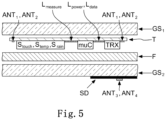
- FIG. 3-5 An exemplary layer stack for implementing a wireless sensor system in glass products is shown, exemplified in the case of laminated glass.
- a combination film F is inserted between the first glass layer GS 1 and the second glass layer GS 2 , in which there may be gaps, e.g.
- the evaluation unit muC and the actual sensor S touch , S temp , S break , S rain can be cut.
- the functionality of the conductive layer LS can also be used, for example as a capacitive sensor. If the TRX transmitter/receiver unit, muC evaluation unit, S touch , S temp , S break , S rain are attached to a flexible, sufficiently thin PET film, no cutouts need to be made in the combination film F and the TRX transmitter/receiver unit, muC evaluation unit and S touch , S temp , S break , S rain can be laminated directly.
- the connections L power , L data , L measure between transmitter/receiver unit TRX, evaluation unit muC and S touch , S temp , S break , S rain can be made in various ways and, for example, via laser formatting of the conductive coating LS, via a laser formatted silver-printed one PET layer F 2 can be made using thin wires or silver printing.
- the power supply device (ANT 3 ) for providing electromagnetic power to the receiving antenna (ANT 1 ) for coupling the power into the transceiver unit TRX and a data receiving device (ANT 4 ) for receiving data from the transmitting antenna (ANT 2 ) are outside the pane built up.
- these can be outside the visible range, eg under or on the black print SD as a silver print, but also with the help of wires.
- Such laminated glass panes 1 have a thickness of 1 mm to 8 mm, preferably 3.5 to 5.3 mm, and can therefore be further processed without further ado like conventional laminated glass panes.
- the first glass layer GS 1 and/or the second glass layer GS 2 of the laminated glass pane 1 typically have a thickness selected from a range of approximately 1.4 mm to 2.6 mm. As a result, the required properties of splinter protection and/or noise protection are ensured.
- thermoplastic combination film F With the thermoplastic combination film F, a laminated glass pane 1 can thus be produced in a proven manner by obtaining a first glass layer GS 1 and a second glass layer GS 2 , with the thermoplastic film F being placed on the first glass layer GS 1 and Using an autoclave process, the second glass layer GS 2 is placed on the thermoplastic film. The thermoplastic combination film F is then connected to the first glass layer GS 1 and the second glass layer GS 2 in the autoclave and under the action of heat and pressure.
- the sensor arrangement S according to the invention cannot only be used in an autoclave process, but can also be used, for example, with a vacuum thermal oven process or similar autoclave-free processes.
- thermoplastic combination film F In principle, it is also possible to first connect only a first glass layer GS 1 to the thermoplastic combination film F after application and only then to apply the second glass layer GS 2 and to the thermoplastic combination film F pre-connected to the glass layer GS 1 connect.
- Thermoplastic films F produced in this way can be used in laminated glass panes 1 in vehicles, in particular as windshields or buildings or as information displays. A use of a laminated glass pane 1 according to the invention in a head-up display arrangement is also possible.
Landscapes
- Engineering & Computer Science (AREA)
- General Engineering & Computer Science (AREA)
- Theoretical Computer Science (AREA)
- Mechanical Engineering (AREA)
- Human Computer Interaction (AREA)
- Physics & Mathematics (AREA)
- General Physics & Mathematics (AREA)
- Civil Engineering (AREA)
- Automation & Control Theory (AREA)
- Structural Engineering (AREA)
- Joining Of Glass To Other Materials (AREA)
- Support Of Aerials (AREA)
- Instrument Panels (AREA)
- Arrangements For Transmission Of Measured Signals (AREA)
- Details Of Aerials (AREA)
- Laminated Bodies (AREA)
Description
- Die Erfindung betrifft eine Verbundglasscheibe mit einer Sensoranordnung, ein Übertragungssystem und ein Verfahren zur Herstellung der Verbundglasscheibe mit Sensoranordnung.
- Verbundglasscheiben werden heute an vielen Orten, insbesondere im Fahrzeugbau, verwendet. Dabei ist der Begriff Fahrzeug weit gefasst und betrifft unter anderem Straßenfahrzeuge, Flugzeuge, Schiffe, landwirtschaftliche Maschinen oder auch Arbeitsgeräte. Auch in anderen Bereichen werden Verbundglasscheiben verwendet. Hierzu zählen beispielsweise Gebäude-Verglasungen als auch Informationsdisplays, z.B. in Museen oder als Werbedisplays. Dabei weist eine Verbundglasscheibe im Allgemeinen zwei Glasflächen auf, die auf eine Zwischenschicht laminiert sind. Die Glasflächen selbst können eine Krümmung aufweisen und sind in aller Regel von konstanter Dicke. Die Zwischenschicht weist in aller Regel ein thermoplastisches Material, in aller Regel Polyvinylbutyral (PVB), einer vorbestimmten Dicke, z.B. 0,76 mm, auf.
- Häufig besteht der Wunsch, Sensoren unterschiedlicher Art anzubringen. Bisherige Sensoren wurden in eigenen Gehäusen mit eigener Verkabelung auf der Scheibe untergebracht. So wurden z.B. in der Vergangenheit und Gegenwart Regensensoren auf der Innenseite von Autowindschutzscheiben angebracht und mit der entsprechenden Automobilelektronik verkabelt. Verkabelungen und Anschlüsse von Sensoren stellen einen Schwachpunkt dar, denn in Fahrzeugen sind die Verkabelungen und Anschlüsse hohen Temperaturunterschieden und Feuchtigkeitsbereichen ausgesetzt. Hier treten beispielsweise selbst in mittleren Breiten Temperauren von -10° C und bis weit über +70° C auf. Zudem sind Sensorgehäuse häufig optisch unattraktiv und erweisen sich auch als Hindernis bei der Reinigung. Zwar könnte man überlegen einen Sensor innerhalb der Scheibe anzuordnen und elektrische Kontaktierungen durch entsprechende Bohrungen in der Glasscheibe zu führen, jedoch stellt dies eine Schwächung der Scheibe dar, sodass es zum einen schneller zur Rissbildung kommen könnte zum anderen aber auch zu einem Eindringen von Feuchtigkeit und/oder Schmutz und/oder aggressiven Gasen, sodass die Standfestigkeit des Verbundsystems beeinträchtigt oder sogar nachhaltig geschädigt werden könnte. Auch wäre ein Feuchtigkeitseintritt nur schwer wieder zu entfernen, sodass nachhaltig die Transmission der Scheibe beeinträchtigt sein könnte. Zudem ist durch die Verkabelung der Ort eines möglichen Sensors auf den nahen Rand einer Verbundglasscheibe eingeschränkt, da Leitungsverbindungen durch das Sichtfeld zum einen nicht statthaft sein können, da gewisse Transmissionsbedingungen erfüllt sein müssen, zum anderen aber auch als störend empfunden werden.
- Beispielsweise ist aus der
WO 2013 / 091 961 A1 eine Verbundglasscheibe bekannt, die einen randständigen Sensor und eine randständige Antenne aufweist. - Aus der
JP 2004 334445 A -
US 2006/2008905 A1 zeigt eine Verbundscheibe mit einem elektrischen Etikett, das in einer Zwischenschicht im Randbereich der Verbundscheibe angeordnet ist. - Ausgehend von dieser Situation ist es eine Aufgabe der Erfindung eine verbesserte Verbundglasscheibe mit einer Sensoranordnung, ein verbessertes Übertragungssystem und ein Verfahren zur Herstellung der Verbundglasscheibe mit Sensoranordnung bereitzustellen, wobei bisherige Probleme vermieden werden sollen.
- Die Aufgabe wird durch eine erfindungsgemäße Verbundglasscheibe gelöst.
- Die Erfindung ist definiert durch die unabhängigen Ansprüche.
- Weitere vorteilhafte Ausführungsformen sind in den abhängigen Ansprüchen definiert.
- Mittels der erfindungsgemäßen Verbundglasscheibe ist es möglich, auf bisherige Gehäuse von Sensoren zu verzichten und zudem den Verkabelungsaufwand zu reduzieren. Weiterhin erlaubt die Erfindung Sensoren freier zu platzieren.
- In einer Weiterbildung der Erfindung sind die Empfangsantenne und die Sendeantenne in einer physikalischen Antenne vereint. Hierdurch kann erreicht werden, dass der Aufwand für Bauelemente reduziert wird.
- Erfindungsgemäß ist die Sensoranordnung auf der Kombinationsfolie oder einem Träger innerhalb der Verbundglasscheibe aufgebracht. Durch die Anbringung auf der Kombinationsfolie oder einem Träger kann die Herstellung vereinfacht werden.
- In einer Weiterbildung der Erfindung weist die Sensoranordnung einen Temperatursensor und/oder einen Lichtsensor und/oder einen Berührungssensor und/oder einen Bruchsensor und/oder einen Regensensor auf. Durch die Erfindung wird es ermöglicht, einen Sensor oder mehrere Sensoren vereinfacht anzubringen und auszulesen.
- Erfindungsgemäß weist die Sensoranordnung eine Auswerteeinheit zur Evaluierung von Information eines Sensors und zur Erstellung von Information zur Weitergabe an die Sendeantenne auf. Hierdurch kann bereits eine Vielzahl von Sensordaten vorverarbeitet werden, sodass nur wenige Informationen an andere Einrichtungen zur Verfügung gestellt werden müssen. Hierdurch sinkt der Implementierungsaufwand für die Datenübertragung.
- Gemäß einer Weiterbildung der Erfindung sind zumindest Teile der Sendeantenne und/oder der Empfangsantenne als Drähte auf oder in der Kombinationsfolie aufgebracht bzw. eingebracht. Durch die Anbringung auf der Kombinationsfolie kann die Herstellung vereinfacht werden.
- Gemäß noch einer Weiterbildung der Erfindung nutzt die Sensoranordnung die Sendeantenne und/oder die Empfangsantenne als Sensor. Hierdurch kann erreicht werden, dass der Aufwand für Bauelemente reduziert wird.
- Erfindungsgemäß sind die Leistungsversorgungseinrichtung und die Datenempfangseinrichtung auf einer Außenseite der ersten und/oder der zweiten Glas-Schicht angeordnet. Hierdurch kann ein kostengünstiges Sensorsystem bereitgestellt werden, das lediglich minimalen Verkabelungsaufwand benötigt.
- In einer weiteren Ausgestaltung der Erfindung ist eine Antennenstruktur der Leistungsversorgungseinrichtung und/oder eine Antennenstruktur der Datenempfangseinrichtung als Draht oder als gedruckter elektrischer Leiter ausgebildet. Hierdurch kann erreicht werden, dass der Aufwand für Bauelemente reduziert wird.
- Weiterhin wird die Aufgabe gelöst durch ein Übertragungssystem mit einer erfindungsgemäßen Verbundglasscheibe, die die räumlich von der Sensoranordnung getrennte Leistungsversorgungseinrichtung zur Bereitstellung von elektromagnetischer Leistung an die Empfangsantenne und die Datenempfangseinrichtung zum Empfang von Daten der Sendeantenne aufweist. Hierdurch kann ein kostengünstiges Sensorsystem bereitgestellt werden, das lediglich minimalen Verkabelungsaufwand bei freier Platzierbarkeit der Sensoren benötigt.
- In einer Weiterbildung der Erfindung sind die Leistungsversorgungseinrichtung und die Datenempfangseinrichtung in einer physikalischen Antenne vereint. Hierdurch kann erreicht werden, dass der Aufwand für Bauelemente reduziert wird.
- Gemäß einer Weiterbildung der Erfindung wandelt die Datenempfangseinrichtung von der Sendeantenne erhaltene Informationen um und stellt sie an ein Bus-System zur Verfügung. Hierdurch kann ein kostengünstiges Sensorsystem bereitgestellt werden, das lediglich minimalen Verkabelungsaufwand benötigt.
- Gemäß einer Weiterbildung der Erfindung werden mindestens zwei Sensoren durch eine gemeinsame Leistungsversorgungseinrichtung versorgt und/oder es werden Daten von den zwei Sensoren durch eine gemeinsame Datenempfangseinrichtung empfangen.
- Die Aufgabe wird weiterhin gelöst durch ein Verfahren zur Herstellung einer erfindungsgemäßen Verbundglasscheibe mit einer Sensoranordnung, aufweisend den Schritt des Erhaltens einer Sensoranordnung, den Schritt des Einbringens der Sensoranordnung in ein Vorprodukt der Verbundglasscheibe, wobei der Schritt des Einbringens ausgewählt ist aus Laminieren, Kleben, Auflegen und den Schritt des Fertigstellens der Verbundglasscheibe. Hierdurch kann eine erfindungsgemäße Verbundglasscheibe kostengünstig hergestellt werden.
- Gemäß einer Weiterbildung der Erfindung werden Teile der Sensoranordnung mittels einer Laserformatierung, einer silberbeschichteten Folie, einem Flachleiter oder Siebdruck eingebracht. Hierdurch kann ein weiterer Kosten- und Zeitgewinn bei der Herstellung erzielt werden.
- Ausführungsformen der vorliegenden Erfindung werden in exemplarischer Weise mit Bezug auf die angehängten Zeichnungen beschrieben, welche zeigen:
-
Fig. 1 eine schematische Darstellung einer Verbundglasscheibe gemäß Ausführungsformen der Erfindung, -
Fig. 2 eine schematische Darstellung von elektrischen Komponenten einer Sensoranordnung gemäß Ausführungsformen der Erfindung, -
Fig. 3 eine schematische Schnittdarstellung einer Verbundglasscheibe gemäß Ausführungsformen der Erfindung, -
Fig. 4 eine schematische Schnittdarstellung einer Verbundglasscheibe gemäß Ausführungsformen der Erfindung, -
Fig. 5 eine schematische Schnittdarstellung einer Verbundglasscheibe gemäß Ausführungsformen der Erfindung, und -
Fig. 6 eine schematische Darstellung einer Fahrzeugtür mit einer Verbundglasscheibe gemäß Ausführungsformen der Erfindung. - In
Figur 1 ist eine schematische Darstellung einer Verbundglasscheibe 1 gemäß Ausführungsformen der Erfindung gezeigt. Schematische Schnittdarstellungen einzelner Ausführungsformen sind in denFiguren 3-5 dargestellt. - Die Verbundglasscheibe 1 weist - wie aus den
Figuren 3-5 ersichtlich ist - eine erste Glas-Schicht GS1 und eine zweite Glas-Schicht GS2 auf. Die erste Glas-Schicht GS1 und zweite Glas-Schicht GS2 sind unmittelbar oder mittelbar über eine Kombinationsfolie F verbunden. Mittelbar, wenn zumindest abschnittsweise weitere Materialien lokal oder global zwischen den Glas-Schichten angeordnet sind. Hierzu folgen im Weiteren noch Erläuterungen. - Eine derartige thermoplastische Kombinationsfolie F kann zumindest einen Stoff ausgewählt aus der Gruppe aufweisend Polybutylenterephthalat (PBT), Polycarbonat (PC), Polyethylenterephthalat (PET) und Polyethylennaphthalat (PEN), Polyvinylchlorid (PVC), Polyvinylfluoride (PVF), Polyvinylbutyral (PVB), Ethylenvinylacetat (EVA), Polyacrylat (PA), Polymethylmethacrylat (PMMA), Polyurethan (PUR), und/oder Gemische und Copolymere davon enthalten.
- Die erfindungsgemäße Verbundglasscheibe 1 weist weiterhin eine Sensoranordnung S auf. Eine schematische Darstellung von elektrischen Komponenten der Sensoranordnung gemäß Ausführungsformen der Erfindung ist in
Figur 2 dargestellt. Dabei wird nachfolgend nur die logische Struktur beschrieben werden, während Vorschläge einer tatsächlichen Implementierung erst später beschrieben werden. - Die Sensoranordnung S weist zum einen eine (logische) Empfangsantenne ANT1 zum Erhalt elektrischer Leistung zur Versorgung der Sensoranordnung S und eine (logische) Sendeantenne ANT2 zur Bereitstellung von Information der Sensoranordnung S an eine außerhalb der Verbundglasscheibe befindliche Empfangseinheit auf. Die Sensoranordnung S befindet sich dabei teilweise oder vollständig zwischen der ersten Glas-Schicht GS1 und der zweiten Glas-Schicht GS2.
- Dabei kann eine Sensoranordnung S einen oder mehrere Sensoren aufweisen. Beispielhaft seien hier Regensensoren Srain, z.B. zur Erkennung von Regen/Eis, z.B. auf einer Windschutzscheibe, Temperatursensoren Stemp, z.B. zur Messung der Temperatur, Lichtsensoren, z.B. zur Erkennung einer Umgebungshelligkeit, Berührungssensoren Stouch, z.B. für Bedienungselemente eines Head-Up-Displays, Bruchsensor Sbreak, z.B. zur Erkennung von Beschädigungen der Verbundglasscheibe 1, genannt. Die Verbundglasscheibe 1 kann auch mehrere Sensoranordnungen S aufweisen.
- Beispielsweise kann die Sensoranordnung in die in
Figur 2 schematisch dargestellten logischen Blöcke aufgeteilt sein. So kann z.B. eine Sende-/Empfangseinheit TRX vorgesehen sein, die mittels der (logischen) Antennen ANT1 und ANT2 Energie für die Sensoranordnung bezieht als auch Informationen an die hierzu externe Empfangseinheit zur Verfügung stellt. Diese Sende-/Empfangseinheit TRX stellt über eine geeignet hergestellte (logische) Verbindung Lpower nachfolgenden Einrichtungen elektrische Energie zur Verfügung. Beispielhaft ist hier ein (optionaler) Microcontroller muC als eine Auswerteeinheit zur Evaluierung von Information eines Sensors und ein Sensor Srain, Stemp, Stouch dargestellt. Der Sensor Srain, Stemp, Stouch ist über eine geeignet hergestellte (logische) Verbindung Lmeasure verbunden. Dabei kann hier sowohl eine direkte Messung vorgesehen sein, d.h. der Sensor ändert z.B. unter Einfluss der zu messenden Größe einen Strom/eine Spannung/eine Änderung der Resonanzfrequenz der Antenne hervorgerufen durch eine Änderung der Induktivität oder Kapazität hervorgerufen durch die Änderung der dielektrischen Eigenschaften des Sensors oder der Umgebung des Sensors, die nachfolgend ausgewertet werden kann, oder aber der Sensor stellt Daten zur Verfügung. D.h. die logische Verbindung Lmeasure kann sowohl der Energieversorgung als auch der Daten/Messwert-Bereitstellung dienen. Im Falle, dass eine Auswertung der Daten/Messwerte durch eine Auswerteeinheit muC vorgenommen wird, können die aufbereiteten Daten als Information über die logische Verbindung Ldata an die Sende-/Empfangseinheit TRX zur Verfügung gestellt werden. Die Sende-/Empfangseinheit stellt dann die Information über die (logische) Antenne ANT2 an die externe Empfangseinheit zur Verfügung. D.h. Daten des Sensors Srain, Stemp, Stouch können sowohl unmittelbar mittels der Sende-/Empfangseinheit TRX zur Verfügung gestellt werden als auch in Ausführungsformen mittels einer Auswerteeinrichtung muC vorverarbeitet werden. - Dieser Verbundglasscheibe 1 steht als interagierendes Element innerhalb eines Übertragungssystems eine räumlich von der Sensoranordnung S getrennte (logische) Leistungsversorgungseinrichtung ANT3 zur Bereitstellung von elektromagnetischer Leistung an die Empfangsantenne ANT1 und eine (logische) Datenempfangseinrichtung ANT4 zum Empfang von Daten der Sendeantenne ANT2 gegenüber. Nunmehr kann mittels der Leistungsversorgungseinrichtung ANT3 Energie z.B. mittels elektromagnetischer Wechselfelder an die Empfangsantenne ANT1 übertragen werden, ohne dass es einer störenden Versorgungsleitung auf oder zwischen den Glas-Schichten GS1 und GS2 bedarf. Ebenso können Informationen der Sensoranordnung S mittels der Sendeantenne ANT2 an eine außerhalb der Verbundglasscheibe 1 befindliche Empfangseinheit, nämlich der Datenempfangseinrichtung ANT4, übertragen werden, ohne dass es einer störenden Versorgungsleitung auf oder zwischen den Glas-Schichten GS1 und GS2 bedarf. Dabei kann in Bezug auf die Sensoranordnung S auf ein Gehäuse verzichtet werden, denn die Sensoranordnung S ist zwischen den Glas-Schichten geschützt. Zudem muss keine Verkabelung der Sensoranordnung S vorgesehen werden, wodurch die Fehleranfälligkeit bisheriger Systeme vermieden wird. Zudem können die Sensoren an ergonomisch sinnvollen oder messtechnisch vorteilhafteren Stellen platziert werden, ohne eine Gefahr für die Transmission darzustellen. Damit sind die bisherigen Limitierungen zur Platzierung aufgehoben und es wird somit auch die innovative Integration neuer Sensorkonzepte, z.B. in ein graphisches Benutzersystem, ermöglicht.
- Beispielsweise ist in
Figur 6 eine Autotür dargestellt. Die Verbundglasscheibe 1 weist wie zuvor beschrieben eine Sensoranordnung auf. Dabei ist ein Sensor Stouch für ein schlüsselloses Zugangssystem vorgesehen. Der Sensor Stouch ist über eine elektrische Verbindung Lmea-sure innerhalb der Verbundglasscheibe 1 mit einer kombinierten Auswerteeinheit und Sende- / Empfangseinheit muC/TRX verbunden. Die kombinierte Auswerteeinheit und Sende- / Empfangseinheit muC/TRX wiederum ist an eine (logische) Empfangsantenne ANT1 und eine (logische) Sendeantenne ANT2 angebunden. Mittels einer in der Tür, z.B. in der Türinnenverkleidung, angeordneten (logischen) Leistungsversorgungseinrichtung ANT3 und einer (logischen) Datenempfangseinrichtung ANT4 kann nunmehr der Sensor Stouch als auch die kombinierte Auswerteeinheit und Sende- / Empfangseinheit muC/TRX mit elektrischer Energie (kontaktlos) versorgt werden bzw. Daten ausgelesen werden. Da die Seitenscheibe in aller Regel öffenbar gestaltet ist, kann durch eine geschickte Anordnung und Ausgestaltung der (logischen) Empfangsantenne ANT1 und der (logischen) Sendeantenne ANT2 erreicht werden, dass weitestgehend unabhängig vom Öffnungsgrad, d.h. einem Einschieben in den Türrahmen, die (logische) Empfangsantenne ANT1 und die (logische) Sendeantenne ANT2 im Einflussbereich der (logischen) Leistungsversorgungseinrichtung ANT3 und der (logischen) Datenempfangseinrichtung ANT4 verbleiben. Die von der (logischen) Datenempfangseinrichtung ANT4 empfangenen Daten können dann z.B. an die Fahrzeugsteuerung weitergereicht werden, um z.B. die Türen freizugeben oder aber bei einer Vielzahl von Fehlversuchen eine Alarmierung zu veranlassen. Durch die Anordnung innerhalb der Scheibe und die drahtlose Anbindung können je nach Ausgestaltung des Sensors Stouch zahlreiche insbesondere andernfalls als beweglich auszugestaltende Kabelverbindungen entfallen, sodass zum einen die Verfügbarkeit eines solchen schlüssellosen Zugangssystems erhöht wird, zum anderen aber auch bisherige Schwierigkeiten, wie z.B. die Integration in die Karosserie eines Fahrzeuges, vermieden werden können. Weiterhin ist von Vorteil, dass die Anordnung so gestaltet werden kann, dass im Wesentlichen keine Verlustleistung durch Abstrahlung entsteht, da die Antennen abgestimmt aufeinander angeordnet werden können. Hierdurch wird die Gefahr eines Abhörens der Kommunikation vermindert. Weiterhin vorteilhaft kann die (logische) Empfangsantenne ANT1 und die (logische) Sendeantenne ANT2 innerhalb der Verbundglasscheibe 1 so angeordnet sein, dass sie (jeweils) nicht in den Blickbereich eines Benutzers geraten, z.B. indem sie unterhalb der sogenannten daylight-line angeordnet sind. Die daylight-line entspricht bei geschlossener Scheibe der Überdeckung durch die Türverkleidung. - In einer vorteilhaften Ausgestaltung können die Empfangsantenne ANT1 und die Sendeantenne ANT2 in einer physikalischen Antenne vereint sein. Dies ist in aller Regel ohne Störung möglich. Beispielsweise kann ein halb-Duplex Übertragungsprotokoll vorgesehen sein, sodass in einem ersten Zeitintervall Energie zur Verfügung gestellt wird und in einem zweiten Zeitintervall Daten zur Verfügung gestellt werden. Diese (physikalische) Vereinigung der logischen Antennen ANT1 und ANT2 reduziert den Bauteilaufwand und minimiert den Flächenbedarf für die Antennen. Somit wird der Bereich, in dem eine verminderte Transparenz unter Umständen gegeben wäre, klein gehalten.
- In einer weiteren Ausgestaltung, die alternativ oder zusätzlich Verwendung finden kann, ist die Sensoranordnung S als Ganzes oder in Teilen, d.h. die Empfangsantenne ANT1 und/oder die Sendeantenne ANT2 und/oder eine optional vorhandene Auswerteeinheit TRX auf der Kombinationsfolie F oder einem Träger T innerhalb der Verbundglasscheibe 1 aufgebracht. Der Träger T kann z.B. ebenfalls aus einem Material wie die Kombinationsfolie F gefertigt sein und als Einlegestück in einen korrespondierenden Ausschnitt der Kombinationsfolie F bei der Fertigung eingefügt werden, z.B. vor der verbindenden Wärmebehandlung in einem Autoklaven.
- Wie bereits beschrieben, kann die Sensoranordnung S unterschiedliche Arten und Anzahlen von Sensoren aufweisen, beispielsweise einen Temperatursensor Stemp und/oder einen Lichtsensor und/oder einen Berührungssensor Stouch und/oder einen Bruchsensor Sbreak und/oder einen Regensensor Srain.
- In einzelnen Ausführungsformen ist zudem vorgesehen, dass die Sensoranordnung S eine Auswerteeinheit muC zur Evaluierung von Information eines Sensors Stouch, Stemp, Sbreak, Srain und zur Erstellung von Information zur Weitergabe an die Sendeantenne aufweist. Hiermit kann die Datenmenge, die zu übertragen wäre, reduziert werden und eine Vorverarbeitung der Rohdaten vorgenommen werden. Die Auswerteeinheit muC kann beispielsweise mittels eines digitalen Signalprozessors, eines MikroControllers, eines ASICs (application-specific integrated circuit) oder eines FPGA (Field Programmable Gate Array) implementiert sein, ohne jedoch auf diese Beispiele beschränkt zu sein. Ohne weiteres können die Sende-/Empfangseinheit TRX und die Auswerteeinheit auch in einer Einheit vereinigt sein.
- In einer Ausbildung der Erfindung kann vorgesehen sein, dass der Sendeantenne ANT1 und/oder der Empfangsantenne ANT2 eine Doppelfunktion zukommt. So können z.B. die Sendeantenne und/oder die Empfangsantenne auch Teile eines Sensors sein und so z.B. Kapazitätsänderungen infolge von Berührung und/oder Benetzung (Regensensor) und/oder Bruch messen und wie bereits zuvor beschrieben direkt oder vorverarbeitet der Sendeempfangseinheit TRX zur Verfügung stellen.
- In einer Ausgestaltung der Erfindung sind zumindest Teile der Sendeantenne ANT1 und/oder der Empfangsantenne ANT2 als Drähte auf die Kombinationsfolie F aufgebracht bzw. oder in die Kombinationsfolie F eingebracht.
- Beispielsweise sind Drähte auf einer Kombinationsfolie in
Figur 4 dargestellt. Hier sind Leiterbahnen auf einer Kombinationsfolie F2 aufgebracht. Die Kombinationsfolie F2 kann aus demselben Material wie die Kombinationsfolie F oder aus einem anderen Material wie es für Kombinationsfolien geeignet ist, bestehen. Darüber hinaus kann das Material auch hiervon abweichen, z.B. eine Polyethylen-Folie oder eine PET-Folie (Polyethylenterephthalat), dann kann es jedoch unter Umständen erforderlich sein, zwischen der Glas-Schicht GS1 und der Kombinationsfolie F2 noch eine weitere geeignete (und der Einfachheit halber nicht dargestellte) Kombinationsfolie einzufügen. Alternativ oder zusätzlich können die Leiterbahnen auch in die Kombinationsfolie F eingelagert sein. - Alternativ oder zusätzlich können Drähte der Sendeantenne ANT1 und/oder der Empfangsantenne ANT2 und/oder die Verbindung Lpower, Lmeasure, Ldata auch (zumindest abschnittsweise) als strukturierte leitende Schicht LS - wie in
Figur 3 gezeigt - implementiert sein. Typische Verfahren hierzu sind z.B. die Herstellung von laserformatierten Linien in einer leitfähigen Beschichtung LS des Glases oder einer zusätzlichen leitfähig beschichteten Kombinationsfolie F2 oder Träger T, z.B. silberbeschichteten Folie, einem Flachleiter oder Silberdruck. - In der bisherigen Beschreibung wurde die Sensoranordnung beschrieben. Nun wenden wir uns der Beschreibung der Leistungsversorgungseinrichtung ANT3 und/oder der Datenempfangseinrichtung ANT4 zu. Die Leistungsversorgungseinrichtung ANT3 und/oder die Datenempfangseinrichtung ANT4 kann in geeigneter Form räumlich getrennt von der Sensoranordnung in der Nachbarschaft angeordnet sein. Dabei ist es zum Beispiel möglich, die Leistungsversorgungseinrichtung ANT3 und/oder der Datenempfangseinrichtung ANT4 im Rahmen einer Verbundglasscheibe 1 zu platzieren, sodass eine räumliche Nachbarschaft gewährleistet ist. Es ist aber auch möglich, entsprechende Einrichtungen in anderen Teilen einzuarbeiten. Beispielsweise wäre es bei einer Verbundglasscheibe in einem Kraftfahrzeug auch möglich, die Leistungsversorgungseinrichtung ANT3 und/oder die Datenempfangseinrichtung ANT4 im Dachhimmel des Fahrzeuges und/oder dem Armaturenbrett des Fahrzeuges und/oder der A-Säulen-Innverkleidung des Fahrzeuges unterzubringen. Gleichfalls ist es möglich, eine Leistungsversorgungseinrichtung ANT3 und/oder eine Datenempfangseinrichtung ANT4 auf einer Außenseite der ersten Glas-Schicht GS1 und/oder der zweiten Glas-Schicht GS2 - wie in den
Figuren 1 ,3-5 gezeigt - anzuordnen. - Typische Verfahren zur Herstellung der Leistungsversorgungseinrichtung ANT3 und/oder der Datenempfangseinrichtung ANt4 sind analog zu der Sendeantenne / Empfangsantenne und können wiederum Techniken wie Silberdruck, Strukturieren von Folien etc. aufweisen, die unter Umständen noch strukturiert werden
- In den
Figuren 1 ,3-5 ist jeweils die Anordnung einer leitenden Schicht auf einem Schwarzdruck SD gezeigt. Typischerweise wird der Schwarzdruck SD am Rand vorgenommen, um eine Verbesserung der Klebefähigkeit von Scheiben am Rand zu erhalten und dem Kleber Schutz vor Sonneneinstrahlung zu bieten. Typischerweise wird Silberdruck zur Ausbildung von Antennen oder einer Heizfunktion vorgenommen. Bei der Erfindung wird dieser bei (Fahrzeug-) Scheiben bereits vorhandene Schwarz- und/oder Silberdruck jetzt mit zusätzlichen Funktionen versehen. - Wie in
Figur 1 angedeutet, kann mittels des Bordnetzes und eines geeigneten Wechselstrom-Erzeugers, z.B. einem DC/AC-Wandler, aus dem Versorgungsnetz BAT des Fahrzeuges eine Wechselspannung erzeugt werden, die mittels einer Leistungsversorgungseinrichtung ANT3, d.h. einer geeignet ausgestalteten Abstrahleinrichtung elektromagnetische Wechselfelder erzeugt, diese in die Empfangseinrichtung ANT1 einkoppeln und so eine drahtlose Versorgung der Sensoranordnung S ermöglichen. - In einer vorteilhaften Ausgestaltung ist die Antennenstruktur der Leistungsversorgungseinrichtung ANT3 und/oder die Antennenstruktur der Datenempfangseinrichtung ANT4 als Draht oder als gedruckter elektrischer Leiter ausgebildet.
- Wie zuvor für die Sensoranordnung beschrieben, können auch die logischen Antennen der Leistungsversorgungseinrichtung ANT3 und der Datenempfangseinrichtung ANT4 in einer physikalischen Antenne vereint sein. Die Informationen bzw. Daten, die von der Sendeantenne ANT2 abgestrahlt werden, können mittels der Datenempfangseinrichtung ANT4 aufgenommen werden. Die erhaltenen Daten können dann (nach Wandlung des HF-Signals und geeigneter Aufbereitung) an ein Bus-System zur Verfügung gestellt werden. Beispielsweise können Daten eines Helligkeitssensors zur Steuerung der Beleuchtung eines Fahrzeuges herangezogen werden, während Daten eines Regensensors zur Steuerung eines Scheibenwischers herangezogen werden, während Daten eines Berührungssensors zur Steuerung von anderen Fahrzeug-bezogenen Funktionen, wie z.B. eines Multi-Media-Systems, herangezogen werden können.
- Ohne weiteres kann das System so dimensioniert werden, dass mindestens zwei Sensoranordnungen S durch eine gemeinsame Leistungsversorgungseinrichtung ANT3 versorgt und/oder durch eine gemeinsame Datenempfangseinrichtung ANT4 Daten empfangen werden können.
- Die erfindungsgemäße Verbundglasscheibe 1 kann auf unterschiedliche Weise gefertigt sein. Ein beispielhaftes Verfahren weist den Schritt des Erhaltens einer Sensoranordnung S, den Schritt des Einbringens der Sensoranordnung S in ein Vorprodukt der Verbundglasscheibe, wobei der Schritt des Einbringens ausgewählt ist aus Laminieren, Kleben, Auflegen, und den Schritt des Fertigstellens der Verbundglasscheibe 1 auf. Dabei können optional Teile der Sensoranordnung S mittels einer Laserformatierung, einer silberbeschichteten Folie, einem Flachleiter oder Siebdruck auf einer der Glas-Schichten oder beiden Glas-Schichten und/oder einer Kombinationsfolie F, F2 und/oder einem Träger T eingebracht werden. Durch die Bereitstellung der Sensoren innerhalb der Verbundglasscheibe 1 entfällt ein vergleichsweise kostenintensiver Schritt der Ausstattung mit einem externen Sensor, wie es aus dem Stand der Technik notwendig ist.
- Mit Hilfe der Erfindung wird ein kontaktfreies Auslesen des Sensors / der Sensoren Stouch, Stemp, Sbreak, Srain sowie deren drahtlose Leistungsversorgung ermöglicht. Hierdurch entfallen Kabelstrecken innerhalb des Automobils/des Fenstersystems, da sowohl die Auslesung als auch die Versorgung drahtlos erfolgt. Bei der Integration einer Vielzahl von Sensoren, die mit Hilfe einer gemeinsamen Leistungsversorgungseinrichtung ANT3 versorgt und durch eine gemeinsame Datenempfangseinrichtung ANT4 ausgelesen werden, verringert sich der Verkabelungsaufwand noch mehr. Sensoren können so auch an Positionen platziert werden, die bei einer kabelgebundenen Anbindung nicht möglich gewesen wären, da diese im Sichtfeld und damit als störend empfunden würden oder sogar den gesetzlichen Bestimmungen zuwiderlaufen könnten.
- Die drahtlose Kommunikation funktioniert aus der Sicht der Sensoranordnung S nach dem Grundprinzip eines aktiven Senders mit Antenne ANT2, die ins Glas integriert ist, und einem passiven Empfänger mit Antenne ANT3, der in Reichweite des Sensors installiert wird. Insbesondere kann sich die Antenne zum Empfang ANT3 auf der Außenseite des Glases oder in direkter Umgebung des Glases eingebettet in das Glasprodukt befinden. Die drahtlose Energieversorgung funktioniert nach dem Prinzip der elektromagnetischen Induktion, mit dem von einer Speisespule ANT4 Energie in eine Empfängerspule ANT1 übertragen werden kann. Aus dem Gesichtspunkt der Energieversorgung ist somit die Spule ANT4 außerhalb des Glases das aktive, die Spule ANT1 innerhalb des Glases das passive Element. Insbesondere können die Spulen zur Energieversorgung gleichzeitig als Antennen zur Kommunikation dienen.
- Die Komponenten der Sensoranordnung S im Glasprodukt sind laminierbar, aufklebbar oder anders im Produkt applizierbar, z.B. als dünne Chips, flexible Leiterpalten oder Elektronik auf Folie oder dünnem, biegbaren Glas. Die Sensoranordnung S im Glasprodukt weist die Empfangsantenne ANT1, eine Sende-/Empfangseinheit TRX, optional eine Auswerteeinheit muC, z.B. einer (flexiblen) Leiterplatte mit integrierten Schaltkreisen (z.B. D/A Wandler), und mindestens einen Sensor, z.B. einen Temperatursensor, einen Berührungssensor, z.B. eine Flächenkapazität (TouchControl, Fingerprint), etc. auf. Insbesondere im Falle einer Flächenkapazität kann eine schon vorhandene leitfähige Beschichtung (wie z.B. bei beheizbaren oder IR reflektierenden Windschutzscheiben oder in Isolierverglasung) formatiert werden (z.B. per Laserschnitt), so dass ein Teil der Beschichtung elektrisch vom Rest der Scheibe entkoppelt ist und somit als Kapazität fungiert.
- Die Sende-/Empfangseinheit TRX weist beispielsweise einen Frequenzgenerator ("Emitter"), eine Empfängereinheit ("Receiver"), und eventuell einen Verstärker auf.
- Die Leistungsversorgungseinrichtung ANT3 und/oder Datenempfangseinrichtung ANT4 kann auch in oder auf Glas, z.B. an dessen Rand, eingebracht werden. Sie kann z.B. aus in die Kombinationsfolie F eingearbeiteten Drähten bestehen oder mit Silberpaste auf dem Glas bzw. auf einem Schwarzdruck aufdruckt werden. Insbesondere kann eine Leistungsversorgungseinrichtung ANT3 zur Versorgung von mehreren drahtlosen Sensoranordnungen S verwendet werden. Ebenso kann eine Datenempfangseinrichtung ANT4 zur Auslesung von mehreren drahtlosen Sensoranordnungen S verwendet werden.
- Die Sensoranordnung S kann an beliebiger Position in einer laminierten Verbundglasscheibe 1 oder an beliebiger Stelle in einer Zwei-/Dreifachverglasung oder in einem anderen Glasprodukt platziert werden.
- Die Sensoranordnung S weist bevorzugt den eigentlichen Sensor Stouch, Stemp, Sbreak, Srain, z.B. eine Kapazität oder ein Thermoelement, welches mittels Lmeasure mit einer Auswerteeinheit muC verbunden ist, auf. Die Auswerteeinheit muC ist z.B. eine (flexible) Leiterplatte mit integrierten Schaltkreisen, welche den Sensor Stouch, Stemp, Sbreak, Srain ausliest und z.B. die Strom-/Spannungscharakteristik des Sensors Stouch, Stemp, Sbreak, Srain interpretiert. Die Verbindung Lmeasure kann je nach Anforderungen und Platzierung des eigentlichen Sensors Stouch, Stemp, Sbreak, Srain und der Auswerteeinheit über dünne Drähte, z.B. laserformatierte Linien in einer leitfähigen Beschichtung des Glases oder einer zusätzlichen silberbeschichteten PET Folie, durch einen Flachleiter oder Silberdruck hergestellt werden. Die Auswerteeinheit muC wird über eine Leistungsleitung Lpower und eine Datenleitung Ldata mit der Sende-/Empfangseinheit TRX verbunden. Lpower, Ldata kann wie Lmeasure beschaffen sein. Die Sende-/Empfangseinheit TRX ist verbunden mit einer Leiterbahn, welche als Spule und Antenne ANT1 respektive ANT2 fungiert. ANT1 respektive ANT2 kann wie Lmeasure beschaffen sein. ANT1 respektive ANT2 koppelt elektromagnetisch an eine außerhalb des sichtbaren Bereiches oder außerhalb des Glasproduktes befindlichen Spule/Antenne ANT3 respektive ANT4, welche einerseits die Signale von der Sende-/Empfangseinheit TRX aufnimmt, andererseits die Sende-/Empfangseinheit TRX induktiv mit Leistung versorgt. Über ANT3 wird elektrische Leistung an die Sensoranordnung S bereitgestellt und über ANT4 werden die Daten der Sensoranordnung S ausgelesen. Auf der Seite der Leistungsversorgungseinrichtung ANT3 ist beispielsweise ein Emitter angeordnet, der elektromagnetische Strahlung zur drahtlosen Leistungsversorgung erzeugt. Die elektromagnetische Strahlung wird über ANT3 abgegeben und von der Sende-/Empfangseinheit TRX über ANT1 empfangen. Weiterhin ist auf der Seite der Datenempfangseinrichtung ANT4 ein Receiver angeordnet, der die von der Sende-/Empfangseinheit TRX generierten und von ANT2 ausgesandten Wellen detektiert. Ein auf Seite der Datenempfangseinrichtung ANT4 angeordneter Analysator/Wandler trennt das Nutzsignal und wandelt es in interpretierbare Daten, z.B. zur Weiterleitung an einen Bus um. In den
Figuren 3-5 ist ein beispielhafter Schichtstapel zur Umsetzung eines drahtlosen Sensorsystems in Glasprodukten gezeigt, beispielhaft gezeigt am Fall von laminiertem Glas. Zwischen der ersten Glas-Schicht GS1 und der zweiten Glas-Schicht GS2 ist eine Kombinationsfolie F eingelegt, in die ggf. Aussparungen, z.B. für die Sende-/Empfangseinheit TRX, die Auswerteeinheit muC und den eigentlichen Sensor Stouch, Stemp, Sbreak, Srain geschnitten werden können. Statt eines eingelegten Sensors Stouch, Stemp, Sbreak, Srain kann auch die Funktionalität der leitfähigen Schicht LS genutzt werden, z.B. als kapazitiver Sensor. Sind Sende-/Empfangseinheit TRX, Auswerteeinheit muC, Stouch, Stemp, Sbreak, Srain auf einer flexiblen, ausreichend dünnen PET Folie aufgebracht, so müssen in die Kombinationsfolie F keine Aussparungen eingebracht werden und Sende-/Empfangseinheit TRX, Auswerteeinheit muC und Stouch, Stemp, Sbreak, Srain können direkt laminiert werden. Die Verbindungen Lpower, Ldata, Lmeasure zwischen Sende-/Empfangseinheit TRX, Auswerteeinheit muC und Stouch, Stemp, Sbreak, Srain können auf verschiedene Weise hergestellt werden und z.B. über Laserformatierung der leitfähigen Beschichtung LS, über eine laserformatierte silberbedruckte PET Schicht F2, über dünne Drähte oder Silberdruck hergestellt sein. Gleiches gilt für die Antenne/Spule ANT1 und ANT2. Die Leistungsversorgungseinrichtung (ANT3) zur Bereitstellung von elektromagnetischer Leistung an die Empfangsantenne (ANT1) zum Einkoppeln der Leistung in die Sende-/Empfangseinheit TRX und eine Datenempfangseinrichtung (ANT4) zum Empfang von Daten der Sendeantenne (ANT2) sind außerhalb der Scheibe aufgebaut. - Ferner können diese, was nicht Teil des Erfindungsumfangs ist, außerhalb des sichtbaren Bereichs, z.B. unter oder auf dem Schwarzdruck SD als Silberdruck, aber auch mit Hilfe von Drähten aufgebaut werden.
- Solche Verbundglasscheiben 1 weisen eine Dicke von 1 mm bis 8 mm, bevorzugt 3.5 bis 5.3 mm, auf und können somit ohne weiteres wie herkömmliche Verbundglasscheiben weiterverarbeitet werden.
- Dabei weisen die erste Glasschicht GS1 und/oder die zweite Glasschicht GS2 der Verbundglasscheibe 1 typischerweise eine Dicke, ausgewählt aus einem Bereich von etwa 1.4 mm bis 2.6 mm, auf. Hierdurch werden die geforderten Eigenschaften an einen Splitterschutz und/oder einen Schallschutz gewährleistet.
- Mit der thermoplastischen Kombinationsfolie F kann somit in bewährter Weise eine Verbundglasscheibe 1 hergestellt werden, indem eine erste Glas-Schicht GS1 und eine zweite Glas-Schicht GS2 erhalten werden, wobei die thermoplastische Folie F auf die erste Glasschicht GS1 aufgelegt wird und bei Verwendung eines Autoklaven-Prozesses auf die thermoplastische Folie die zweite Glasschicht GS2 aufgelegt wird. Anschließend wird die thermoplastische Kombinationsfolie F mit der ersten Glas-Schicht GS1 und der zweiten GlasSchicht GS2 im Autoklaven und unter Wärme- und Druckeinwirkung verbunden. Natürlich ist die erfindungsgemäße Sensoranordnung S nicht nur in einem Autoklaven-Prozess verwendbar, sondern kann z.B. auch mit einem Vakuum-Thermo-Ofen-Prozess oder dergleichen autoklavenfreien Prozessen verwendet werden.
- Auch ist es prinzipiell möglich, zunächst nur eine erste Glas-Schicht GS1 mit der thermoplastischen Kombinationsfolie F nach Auflage zu verbinden und anschließend erst die zweite Glas-Schicht GS2 aufzulegen und mit der mit der Glas-Schicht GS1 vorverbundenen thermoplastischen Kombinationsfolie F zu verbinden. Derartig hergestellte thermoplastische Folien F können in Verbundglasscheiben 1 in Fahrzeugen, insbesondere als Windschutzscheibe oder Gebäuden oder als Informationsdisplay verwendet werden. Eine Verwendung einer erfindungsgemäßen Verbundglasscheibe 1 in einer Head-Up-Display-Anordnung ist ebenfalls möglich.
Claims (13)
- Verbundglasscheibe (1) mit einer Sensoranordnung (S), wobei die Verbundglasscheibe eine erste Glas-Schicht (GS1) und eine zweite Glas-Schicht (GS2) verbunden durch eine Kombinationsfolie (F) und eine zweite Kombinationsfolie (F2) oder eine Kombinationsfolie (F) und eine Trägerschicht (T) aufweist, wobei die Verbundglasscheibe (1) ferner eine Sendeantenne (ANT2),eine Leistungsversorgungseinrichtung (ANT3), undeine Datenempfangseinrichtung (ANT4) aufweist,wobei die Sensoranordnung (S) aufweist- zumindest einen Sensor (Stouch, Stemp, Sbreak, Srain),- eine Empfangsantenne (ANT1) konfiguriert zum Erhalt elektrischer Leistung von der Leistungsversorgungseinrichtung (ANT3) zur Versorgung der Sensoranordnung (S), insbesondere des zumindest einen Sensors (Stouch, Stemp, Sbreak, Srain), wobei die Leistungsversorgungseinrichtung (ANT3) räumlich von der Sensoranordnung (S) getrennt ist,- eine Auswerteeinheit (muC) konfiguriert zur Evaluierung von Information des zumindest einen Sensors (Stouch, Stemp, Sbreak, Srain) und zur Erstellung von Information zur Weitergabe an die Sendeantenne (ANT2),- die Sendeantenne (ANT2) konfiguriert zur Bereitstellung von Information des zumindest einer Sensors (Stouch, Stemp, Sbreak, Srain) oder der Auswerteeinheit (muC) an die Datenempfangseinrichtung (ANT4) wobei die Datenempfangseinrichtung (ANT4) sich außerhalb der Verbundglasscheibe (1) befindet,wobei sich die Sensoranordnung (S) zwischen der ersten Glas-Schicht (GS1) und der zweiten Glas-Schicht (GS2) befindet,wobei die Sensoranordnung (S) auf dem Träger (T) innerhalb der Verbundglasscheibe (1) aufgebracht ist, oder der zumindest eine Sensor (Stouch, Stemp, Sbreak, Srain), und die Auswerteinheit (muC) in Aussparungen der Kombinationsfolie (F) eingebracht oder auf der Kombinationsfolie (F) aufgebracht sind und die Empfangsantenne (ANT1), sowie die Sendeantenne (ANT2) auf der zweiten Kombinationsfolie (F2) aufgebracht sind,dadurch gekennzeichnet, dassdie Leistungsversorgungseinrichtung (ANT3) und die Datenempfangseinrichtung (ANT4) auf einer Außenseite der ersten und/oder der zweiten Glas-Schicht (GS1, GS2) angeordnet ist.
- Verbundglasscheibe (1) nach Anspruch 1, wobei die Empfangsantenne (ANT1) und die Sendeantenne (ANT2) in einer physikalischen Antenne vereint sind.
- Verbundglasscheibe (1) nach Anspruch 1 oder 2, wobei die Sensoranordnung (S) einen Temperatursensor (Stemp) und/oder einen Lichtsensor und/oder einen Berührungssensor (Stouch) und/oder einen Bruchsensor (Sbreak) und/oder einen Regensensor (Srain) aufweist.
- Verbundglasscheibe (1) nach einem der Ansprüche 1 bis 3, wobei zumindest Teile der Sendeantenne (ANT2) und/oder der Empfangsantenne (ANT1) als Drähte auf oder in der Kombinationsfolie (F) aufgebracht bzw. eingebracht sind, wenn die Verbundglasscheibe die erste Glas-Schicht (GS1) und die zweite Glas-Schicht (GS2) verbunden durch die Kombinationsfolie (F) und die zweite Kombinationsfolie (F2) aufweist.
- Verbundglasscheibe (1) nach einem der Ansprüche 1 bis 4, wobei die Sensoranordnung (S) die Sendeantenne (ANT2) und/oder die Empfangsantenne (ANT1) als Sensor (Stouch, Stemp, Sbreak, Srain) nutzt.
- Verbundglasscheibe (1), nach einem der Ansprüche 1 bis 5, wobei eine Antennenstruktur der Leistungsversorgungseinrichtung (ANT3) und/oder eine Antennenstruktur der Datenempfangseinrichtung (ANT4) als Draht oder als gedruckter elektrischer Leiter ausgebildet ist.
- Übertragungssystem mit einer Verbundglasscheibe (1) nach einem der Ansprüche 1 bis 6, weiterhin aufweisend die räumlich von der Sensoranordnung (S) getrennte Leistungsversorgungseinrichtung (ANT3) zur Bereitstellung von elektromagnetischer Leistung an die Empfangsantenne (ANT1) und die Datenempfangseinrichtung (ANT4) zum Empfang von Daten der Sendeantenne (ANT2).
- Übertragungssystem nach Anspruch 7, wobei die Leistungsversorgungseinrichtung (ANT3) und die Datenempfangseinrichtung (ANT4) in einer physikalischen Antenne vereint sind.
- Übertragungssystem nach Anspruch 7 oder 8, wobei die Datenempfangseinrichtung (ANT4) von der Sendeantenne (ANT2) erhaltene Informationen wandelt und an ein Bus-System zur Verfügung stellt.
- Übertragungssystem nach einem der Ansprüche 7 bis 9, wobei mindestens zwei Sensoranordnungen (S) durch eine gemeinsame Leistungsversorgungseinrichtung (ANT3) versorgt werden und/oder eine gemeinsame Datenempfangseinrichtung (ANT4) Daten von den mindestens zwei Sensoranordnungen (S) empfängt.
- Verwendung einer Verbundglasscheibe (1) nach einem der Ansprüche 1 bis 6 in Fahrzeugen oder Gebäuden oder als Informationsdisplay.
- Verfahren zur Herstellung einer Verbundglasscheibe (1) mit einer Sensoranordnung (S) gemäß einem der Ansprüche 1 bis 6, aufweisend die Schritte:- Erhalten einer Sensoranordnung (S),- Einbringen der Sensoranordnung (S) in ein Vorprodukt der Verbundglasscheibe, wobei der Schritt des Einbringens ausgewählt ist aus Laminieren, Kleben, Auflegen,- Fertigstellen der Verbundglasscheibe.
- Verfahren nach Anspruch 12, wobei Teile der Sensoranordnung (S) mittels einer Laserformatierung, einer silberbeschichteten Folie, einem Flachleiter oder Siebdruck eingebracht werden.
Applications Claiming Priority (2)
| Application Number | Priority Date | Filing Date | Title |
|---|---|---|---|
| EP16164807 | 2016-04-12 | ||
| PCT/EP2017/054568 WO2017178146A1 (de) | 2016-04-12 | 2017-02-28 | Verbundglasscheibe mit einer sensoranordnung, übertragungssystem und verfahren zur herstellung einer verbundglasscheibe mit einer sensoranordnung |
Publications (2)
| Publication Number | Publication Date |
|---|---|
| EP3443445A1 EP3443445A1 (de) | 2019-02-20 |
| EP3443445B1 true EP3443445B1 (de) | 2023-05-10 |
Family
ID=55759469
Family Applications (1)
| Application Number | Title | Priority Date | Filing Date |
|---|---|---|---|
| EP17707560.3A Active EP3443445B1 (de) | 2016-04-12 | 2017-02-28 | Verbundglasscheibe mit einer sensoranordnung, übertragungssystem und verfahren zur herstellung einer verbundglasscheibe mit einer sensoranordnung |
Country Status (11)
| Country | Link |
|---|---|
| US (1) | US11052640B2 (de) |
| EP (1) | EP3443445B1 (de) |
| JP (2) | JP2019521935A (de) |
| KR (1) | KR102147031B1 (de) |
| CN (1) | CN107438821A (de) |
| BR (1) | BR112018070781A2 (de) |
| CA (1) | CA3020047A1 (de) |
| MA (1) | MA44653A (de) |
| MX (1) | MX389658B (de) |
| RU (1) | RU2705015C1 (de) |
| WO (1) | WO2017178146A1 (de) |
Families Citing this family (21)
| Publication number | Priority date | Publication date | Assignee | Title |
|---|---|---|---|---|
| WO2019026963A1 (ja) * | 2017-08-02 | 2019-02-07 | Agc株式会社 | ガラス用アンテナユニット、アンテナ付きガラス板、およびガラス用アンテナユニットの製造方法 |
| JP2020535098A (ja) | 2017-09-25 | 2020-12-03 | サン−ゴバン グラス フランス | 乗物用ウィンドウ、乗物、及びそれらの製造方法 |
| JP7083290B2 (ja) * | 2018-08-09 | 2022-06-10 | 日本板硝子株式会社 | 乗物の窓ガラス用の合わせガラス |
| KR102598950B1 (ko) * | 2018-09-12 | 2023-11-07 | 현대자동차주식회사 | 차량 도어글래스용 무선전력전송장치 |
| PE20210840A1 (es) * | 2018-09-25 | 2021-05-06 | Saint Gobain | Cristal de vidrio laminado y metodo para su produccion |
| DE102018217970A1 (de) * | 2018-10-19 | 2020-04-23 | Hegla Boraident Gmbh & Co. Kg | Verfahren zur Herstellung einer elektronischen Struktur auf einer Glasscheibe sowie Glastafel mit mindestens einer derartigen Glasscheibe |
| CN111727357B (zh) * | 2019-01-22 | 2024-11-01 | 法国圣戈班玻璃厂 | 具有方向依赖性的光传感器的运输工具玻璃板 |
| US12374775B2 (en) * | 2019-01-31 | 2025-07-29 | Agc Glass Europe | Insulating glazing unit with antenna unit |
| KR20200111979A (ko) * | 2019-03-20 | 2020-10-05 | 현대자동차주식회사 | 차량 도어글래스용 무선전력전송장치 |
| US11095016B2 (en) * | 2019-04-15 | 2021-08-17 | Hyundai Motor Company | Vehicle roof having conductive coating for wireless communication |
| FR3097163B1 (fr) * | 2019-06-13 | 2021-06-18 | Saint Gobain | Vitrage feuilleté intégrant les antennes du système automatique d’aide à l’atterrissage |
| CN110576804B (zh) * | 2019-08-09 | 2021-04-20 | 福耀玻璃工业集团股份有限公司 | 车窗组件及车辆 |
| US11780594B2 (en) * | 2019-10-02 | 2023-10-10 | Ppg Industries Ohio, Inc. | Transparency including a wireless sensor |
| EP4071926A4 (de) * | 2019-12-03 | 2023-12-27 | Kuraray Co., Ltd. | Antennensystem und antennenleiterplatte |
| US12068524B2 (en) * | 2019-12-05 | 2024-08-20 | Saint-Gobain Glass France | Vehicle pane |
| CN112909497A (zh) * | 2021-02-09 | 2021-06-04 | 福耀玻璃工业集团股份有限公司 | 天线组件及车辆 |
| JP7823336B2 (ja) * | 2021-09-01 | 2026-03-04 | Agc株式会社 | 車両用窓ガラス |
| CN113682035B (zh) * | 2021-09-22 | 2023-11-03 | 福耀集团(福建)机械制造有限公司 | 夹层玻璃的合片系统及合片方法 |
| US12311637B2 (en) | 2022-11-04 | 2025-05-27 | Agc Automotive Americas Co. | Laminated glazing assembly including an antenna assembly |
| US12340054B2 (en) | 2022-12-23 | 2025-06-24 | Shanghai Tianma Micro-electronics Co., Ltd. | Touch panel and display device |
| KR20250130602A (ko) * | 2022-12-28 | 2025-09-02 | 세키스이가가쿠 고교가부시키가이샤 | 접합 유리 및 접합 유리용 복합화 중간막 |
Citations (2)
| Publication number | Priority date | Publication date | Assignee | Title |
|---|---|---|---|---|
| JP2004334445A (ja) * | 2003-05-06 | 2004-11-25 | Secom Co Ltd | セキュリティガラス及びガラス破壊検知装置 |
| US20060208905A1 (en) * | 2005-03-04 | 2006-09-21 | Shohei Ohara | Panel |
Family Cites Families (20)
| Publication number | Priority date | Publication date | Assignee | Title |
|---|---|---|---|---|
| JPH0662134A (ja) * | 1992-08-10 | 1994-03-04 | Nippon Telegr & Teleph Corp <Ntt> | センサ電話機 |
| JP2592071Y2 (ja) * | 1993-02-09 | 1999-03-17 | 株式会社共立 | 立体駐車場 |
| DE19532431C2 (de) | 1995-09-02 | 1998-07-02 | Flachglas Automotive Gmbh | Antennenscheibe in zumindest einer Fensteröffnung einer metallischen Karosserie eines Kraftfahrzeugs, insbesondere Personenkraftfahrzeugs |
| US20040185195A1 (en) * | 2002-08-06 | 2004-09-23 | Anderson Christopher C. | Laminated glass and structural glass with integrated lighting, sensors and electronics |
| JP4107204B2 (ja) * | 2003-09-04 | 2008-06-25 | 株式会社デンソー | 車両用センサ構造体及び車両用通信端末構造体 |
| JP2007328380A (ja) * | 2004-09-13 | 2007-12-20 | Toshin:Kk | ガラス部材損壊と侵入検知方法 |
| US7119751B2 (en) * | 2005-03-11 | 2006-10-10 | Agc Automotive Americas R&D, Inc. | Dual-layer planar antenna |
| US9371032B2 (en) * | 2006-01-10 | 2016-06-21 | Guardian Industries Corp. | Moisture sensor and/or defogger with Bayesian improvements, and related methods |
| US7847745B2 (en) | 2007-11-20 | 2010-12-07 | Centre Luxembourgeois De Recherches Pour Le Verre Et La Ceramique S.A. (C.R.V.C.) | Windshield antenna and/or vehicle incorporating the same |
| JP4604094B2 (ja) * | 2008-01-23 | 2010-12-22 | トヨタ自動車株式会社 | 車両用給電装置および車両用窓材 |
| DE102009017385A1 (de) * | 2009-04-14 | 2010-10-21 | GM Global Technology Operations, Inc., Detroit | Verbundscheibenanordnung |
| DE202009017952U1 (de) * | 2009-09-25 | 2010-09-23 | Saint-Gobain Sekurit Deutschland Gmbh & Co. Kg | Verglasung mit integrierter Schaltvorrichtung |
| EP3425450B1 (de) * | 2009-12-22 | 2021-11-24 | View, Inc. | Drahtlos angetriebene elektrochrome fenster |
| JP2014140088A (ja) * | 2011-05-10 | 2014-07-31 | Asahi Glass Co Ltd | ガラスアンテナ及び窓ガラス |
| ES2823755T3 (es) | 2011-12-20 | 2021-05-10 | Saint Gobain | Cristal compuesto con estructura de antena y superficie de conmutación integrada |
| PT2822728T (pt) * | 2012-03-05 | 2018-11-21 | Saint Gobain | Processo para a produção de um painel de vidro laminado com janela de sensor |
| CN102749771B (zh) | 2012-04-06 | 2015-02-04 | 信利工业(汕尾)有限公司 | 一种集成nfc天线的薄膜晶体管显示器 |
| US9120187B2 (en) * | 2012-06-08 | 2015-09-01 | Nokia Technologies Oy | Multilayer 3D glass window with embedded functions |
| TWI499953B (zh) * | 2012-09-07 | 2015-09-11 | Jieng Tai Internat Electric Corp | 觸控面板、顯示裝置及電子裝置 |
| FR3034500A1 (fr) * | 2015-04-03 | 2016-10-07 | Saint Gobain | Vitrage lumineux de vehicule automobile et vehicule automobile avec un tel vitrage |
-
2017
- 2017-02-28 US US16/091,103 patent/US11052640B2/en active Active
- 2017-02-28 CN CN201780000397.6A patent/CN107438821A/zh active Pending
- 2017-02-28 CA CA3020047A patent/CA3020047A1/en not_active Abandoned
- 2017-02-28 RU RU2018139485A patent/RU2705015C1/ru active
- 2017-02-28 MX MX2018012413A patent/MX389658B/es unknown
- 2017-02-28 EP EP17707560.3A patent/EP3443445B1/de active Active
- 2017-02-28 BR BR112018070781A patent/BR112018070781A2/pt not_active Application Discontinuation
- 2017-02-28 KR KR1020187032265A patent/KR102147031B1/ko active Active
- 2017-02-28 WO PCT/EP2017/054568 patent/WO2017178146A1/de not_active Ceased
- 2017-02-28 JP JP2018553485A patent/JP2019521935A/ja not_active Withdrawn
- 2017-02-28 MA MA044653A patent/MA44653A/fr unknown
-
2021
- 2021-10-22 JP JP2021173082A patent/JP7263482B2/ja active Active
Patent Citations (2)
| Publication number | Priority date | Publication date | Assignee | Title |
|---|---|---|---|---|
| JP2004334445A (ja) * | 2003-05-06 | 2004-11-25 | Secom Co Ltd | セキュリティガラス及びガラス破壊検知装置 |
| US20060208905A1 (en) * | 2005-03-04 | 2006-09-21 | Shohei Ohara | Panel |
Also Published As
| Publication number | Publication date |
|---|---|
| JP2019521935A (ja) | 2019-08-08 |
| CN107438821A (zh) | 2017-12-05 |
| RU2705015C1 (ru) | 2019-11-01 |
| MX389658B (es) | 2025-03-20 |
| US20190152194A1 (en) | 2019-05-23 |
| MA44653A (fr) | 2019-02-20 |
| MX2018012413A (es) | 2019-02-21 |
| WO2017178146A1 (de) | 2017-10-19 |
| KR20180134370A (ko) | 2018-12-18 |
| CA3020047A1 (en) | 2017-10-19 |
| KR102147031B1 (ko) | 2020-08-21 |
| JP7263482B2 (ja) | 2023-04-24 |
| JP2022022212A (ja) | 2022-02-03 |
| EP3443445A1 (de) | 2019-02-20 |
| US11052640B2 (en) | 2021-07-06 |
| BR112018070781A2 (pt) | 2019-02-05 |
Similar Documents
| Publication | Publication Date | Title |
|---|---|---|
| WO2017178146A1 (de) | Verbundglasscheibe mit einer sensoranordnung, übertragungssystem und verfahren zur herstellung einer verbundglasscheibe mit einer sensoranordnung | |
| EP3281248B1 (de) | Antennenscheibe | |
| DE69427782T2 (de) | Verfahren zur Herstellung einer Scheibenantenne und Scheibenantenne | |
| EP3281247B1 (de) | Fahrzeugantennenscheibe | |
| EP3247558B1 (de) | Verbundscheibe mit kapazitivem schaltbereich | |
| EP3941741B1 (de) | Verbundscheibe mit einem funktionalen einlegeelement | |
| EP3847581B1 (de) | Fahrzeugscheibe mit einem transponder | |
| DE19832228A1 (de) | Antennenscheibe für Kraftfahrzeuge | |
| EP2572403B1 (de) | Bandbreitenoptimierte antenne durch hybriden aufbau aus flächen- und linienstrahler | |
| EP3374972A1 (de) | Fahrzeugantennenscheibe oder fahrzeugscheibenantenne für ein mautbezahlsystem | |
| EP2795720A1 (de) | Verbundscheibe mit antennenstruktur und integrierter schaltfläche | |
| EP3449690B1 (de) | Anordnung zum anschluss eines flächenkörpers an eine spannungsversorgung mit eingebetteter steuereinheit | |
| EP3949007A1 (de) | Antennenscheibe | |
| EP3687792B1 (de) | Fahrzeugscheibe, fahrzeug und verfahren zur herstellung | |
| EP2574454B1 (de) | Fensterscheibe mit einer gedruckten Struktur für ein Kraftfahrzeug | |
| EP3856514B1 (de) | Verbundglasscheibe und verfahren zu deren herstellung | |
| EP3900106B1 (de) | Glasscheibe für ein fahrzeug | |
| DE202020005697U1 (de) | Glasscheibe | |
| EP3987441B1 (de) | Beheizbare fahrzeugscheibe mit einem transponder | |
| DE202018006266U1 (de) | Fahrzeugscheibe mit einem Transponder | |
| WO2021185669A1 (de) | Scheibenanordnung mit kapazitivem schaltbereich | |
| DE102024132829A1 (de) | Antennenvorrichtung zur Integration in eine Scheibe | |
| DE202022002761U1 (de) | Verbundscheibensystem | |
| DE202020100648U1 (de) | Fahrzeugverbundscheibe mit Sensoranordnung |
Legal Events
| Date | Code | Title | Description |
|---|---|---|---|
| STAA | Information on the status of an ep patent application or granted ep patent |
Free format text: STATUS: UNKNOWN |
|
| STAA | Information on the status of an ep patent application or granted ep patent |
Free format text: STATUS: THE INTERNATIONAL PUBLICATION HAS BEEN MADE |
|
| PUAI | Public reference made under article 153(3) epc to a published international application that has entered the european phase |
Free format text: ORIGINAL CODE: 0009012 |
|
| STAA | Information on the status of an ep patent application or granted ep patent |
Free format text: STATUS: REQUEST FOR EXAMINATION WAS MADE |
|
| 17P | Request for examination filed |
Effective date: 20180928 |
|
| AK | Designated contracting states |
Kind code of ref document: A1 Designated state(s): AL AT BE BG CH CY CZ DE DK EE ES FI FR GB GR HR HU IE IS IT LI LT LU LV MC MK MT NL NO PL PT RO RS SE SI SK SM TR |
|
| AX | Request for extension of the european patent |
Extension state: BA ME |
|
| DAX | Request for extension of the european patent (deleted) | ||
| RAV | Requested validation state of the european patent: fee paid |
Extension state: MA Effective date: 20181115 |
|
| RAP1 | Party data changed (applicant data changed or rights of an application transferred) |
Owner name: SAINT-GOBAIN GLASS FRANCE |
|
| STAA | Information on the status of an ep patent application or granted ep patent |
Free format text: STATUS: EXAMINATION IS IN PROGRESS |
|
| 17Q | First examination report despatched |
Effective date: 20201023 |
|
| GRAP | Despatch of communication of intention to grant a patent |
Free format text: ORIGINAL CODE: EPIDOSNIGR1 |
|
| STAA | Information on the status of an ep patent application or granted ep patent |
Free format text: STATUS: GRANT OF PATENT IS INTENDED |
|
| INTG | Intention to grant announced |
Effective date: 20221129 |
|
| GRAS | Grant fee paid |
Free format text: ORIGINAL CODE: EPIDOSNIGR3 |
|
| GRAA | (expected) grant |
Free format text: ORIGINAL CODE: 0009210 |
|
| STAA | Information on the status of an ep patent application or granted ep patent |
Free format text: STATUS: THE PATENT HAS BEEN GRANTED |
|
| AK | Designated contracting states |
Kind code of ref document: B1 Designated state(s): AL AT BE BG CH CY CZ DE DK EE ES FI FR GB GR HR HU IE IS IT LI LT LU LV MC MK MT NL NO PL PT RO RS SE SI SK SM TR |
|
| REG | Reference to a national code |
Ref country code: GB Ref legal event code: FG4D Free format text: NOT ENGLISH |
|
| REG | Reference to a national code |
Ref country code: AT Ref legal event code: REF Ref document number: 1567336 Country of ref document: AT Kind code of ref document: T Effective date: 20230515 Ref country code: CH Ref legal event code: EP |
|
| REG | Reference to a national code |
Ref country code: DE Ref legal event code: R096 Ref document number: 502017014703 Country of ref document: DE |
|
| REG | Reference to a national code |
Ref country code: IE Ref legal event code: FG4D Free format text: LANGUAGE OF EP DOCUMENT: GERMAN |
|
| REG | Reference to a national code |
Ref country code: LT Ref legal event code: MG9D |
|
| REG | Reference to a national code |
Ref country code: NL Ref legal event code: MP Effective date: 20230510 |
|
| PG25 | Lapsed in a contracting state [announced via postgrant information from national office to epo] |
Ref country code: SE Free format text: LAPSE BECAUSE OF FAILURE TO SUBMIT A TRANSLATION OF THE DESCRIPTION OR TO PAY THE FEE WITHIN THE PRESCRIBED TIME-LIMIT Effective date: 20230510 Ref country code: PT Free format text: LAPSE BECAUSE OF FAILURE TO SUBMIT A TRANSLATION OF THE DESCRIPTION OR TO PAY THE FEE WITHIN THE PRESCRIBED TIME-LIMIT Effective date: 20230911 Ref country code: NO Free format text: LAPSE BECAUSE OF FAILURE TO SUBMIT A TRANSLATION OF THE DESCRIPTION OR TO PAY THE FEE WITHIN THE PRESCRIBED TIME-LIMIT Effective date: 20230810 Ref country code: NL Free format text: LAPSE BECAUSE OF FAILURE TO SUBMIT A TRANSLATION OF THE DESCRIPTION OR TO PAY THE FEE WITHIN THE PRESCRIBED TIME-LIMIT Effective date: 20230510 Ref country code: ES Free format text: LAPSE BECAUSE OF FAILURE TO SUBMIT A TRANSLATION OF THE DESCRIPTION OR TO PAY THE FEE WITHIN THE PRESCRIBED TIME-LIMIT Effective date: 20230510 |
|
| PG25 | Lapsed in a contracting state [announced via postgrant information from national office to epo] |
Ref country code: RS Free format text: LAPSE BECAUSE OF FAILURE TO SUBMIT A TRANSLATION OF THE DESCRIPTION OR TO PAY THE FEE WITHIN THE PRESCRIBED TIME-LIMIT Effective date: 20230510 Ref country code: PL Free format text: LAPSE BECAUSE OF FAILURE TO SUBMIT A TRANSLATION OF THE DESCRIPTION OR TO PAY THE FEE WITHIN THE PRESCRIBED TIME-LIMIT Effective date: 20230510 Ref country code: LV Free format text: LAPSE BECAUSE OF FAILURE TO SUBMIT A TRANSLATION OF THE DESCRIPTION OR TO PAY THE FEE WITHIN THE PRESCRIBED TIME-LIMIT Effective date: 20230510 Ref country code: LT Free format text: LAPSE BECAUSE OF FAILURE TO SUBMIT A TRANSLATION OF THE DESCRIPTION OR TO PAY THE FEE WITHIN THE PRESCRIBED TIME-LIMIT Effective date: 20230510 Ref country code: IS Free format text: LAPSE BECAUSE OF FAILURE TO SUBMIT A TRANSLATION OF THE DESCRIPTION OR TO PAY THE FEE WITHIN THE PRESCRIBED TIME-LIMIT Effective date: 20230910 Ref country code: HR Free format text: LAPSE BECAUSE OF FAILURE TO SUBMIT A TRANSLATION OF THE DESCRIPTION OR TO PAY THE FEE WITHIN THE PRESCRIBED TIME-LIMIT Effective date: 20230510 Ref country code: GR Free format text: LAPSE BECAUSE OF FAILURE TO SUBMIT A TRANSLATION OF THE DESCRIPTION OR TO PAY THE FEE WITHIN THE PRESCRIBED TIME-LIMIT Effective date: 20230811 |
|
| PG25 | Lapsed in a contracting state [announced via postgrant information from national office to epo] |
Ref country code: FI Free format text: LAPSE BECAUSE OF FAILURE TO SUBMIT A TRANSLATION OF THE DESCRIPTION OR TO PAY THE FEE WITHIN THE PRESCRIBED TIME-LIMIT Effective date: 20230510 |
|
| PG25 | Lapsed in a contracting state [announced via postgrant information from national office to epo] |
Ref country code: SK Free format text: LAPSE BECAUSE OF FAILURE TO SUBMIT A TRANSLATION OF THE DESCRIPTION OR TO PAY THE FEE WITHIN THE PRESCRIBED TIME-LIMIT Effective date: 20230510 |
|
| PG25 | Lapsed in a contracting state [announced via postgrant information from national office to epo] |
Ref country code: SM Free format text: LAPSE BECAUSE OF FAILURE TO SUBMIT A TRANSLATION OF THE DESCRIPTION OR TO PAY THE FEE WITHIN THE PRESCRIBED TIME-LIMIT Effective date: 20230510 Ref country code: SK Free format text: LAPSE BECAUSE OF FAILURE TO SUBMIT A TRANSLATION OF THE DESCRIPTION OR TO PAY THE FEE WITHIN THE PRESCRIBED TIME-LIMIT Effective date: 20230510 Ref country code: RO Free format text: LAPSE BECAUSE OF FAILURE TO SUBMIT A TRANSLATION OF THE DESCRIPTION OR TO PAY THE FEE WITHIN THE PRESCRIBED TIME-LIMIT Effective date: 20230510 Ref country code: EE Free format text: LAPSE BECAUSE OF FAILURE TO SUBMIT A TRANSLATION OF THE DESCRIPTION OR TO PAY THE FEE WITHIN THE PRESCRIBED TIME-LIMIT Effective date: 20230510 Ref country code: DK Free format text: LAPSE BECAUSE OF FAILURE TO SUBMIT A TRANSLATION OF THE DESCRIPTION OR TO PAY THE FEE WITHIN THE PRESCRIBED TIME-LIMIT Effective date: 20230510 Ref country code: CZ Free format text: LAPSE BECAUSE OF FAILURE TO SUBMIT A TRANSLATION OF THE DESCRIPTION OR TO PAY THE FEE WITHIN THE PRESCRIBED TIME-LIMIT Effective date: 20230510 |
|
| REG | Reference to a national code |
Ref country code: DE Ref legal event code: R097 Ref document number: 502017014703 Country of ref document: DE |
|
| REG | Reference to a national code |
Ref country code: DE Ref legal event code: R082 Ref document number: 502017014703 Country of ref document: DE Representative=s name: OBERMAIR, CHRISTIAN, DR. RER. NAT., DE |
|
| PLBE | No opposition filed within time limit |
Free format text: ORIGINAL CODE: 0009261 |
|
| STAA | Information on the status of an ep patent application or granted ep patent |
Free format text: STATUS: NO OPPOSITION FILED WITHIN TIME LIMIT |
|
| 26N | No opposition filed |
Effective date: 20240213 |
|
| PG25 | Lapsed in a contracting state [announced via postgrant information from national office to epo] |
Ref country code: SI Free format text: LAPSE BECAUSE OF FAILURE TO SUBMIT A TRANSLATION OF THE DESCRIPTION OR TO PAY THE FEE WITHIN THE PRESCRIBED TIME-LIMIT Effective date: 20230510 |
|
| PG25 | Lapsed in a contracting state [announced via postgrant information from national office to epo] |
Ref country code: SI Free format text: LAPSE BECAUSE OF FAILURE TO SUBMIT A TRANSLATION OF THE DESCRIPTION OR TO PAY THE FEE WITHIN THE PRESCRIBED TIME-LIMIT Effective date: 20230510 Ref country code: IT Free format text: LAPSE BECAUSE OF FAILURE TO SUBMIT A TRANSLATION OF THE DESCRIPTION OR TO PAY THE FEE WITHIN THE PRESCRIBED TIME-LIMIT Effective date: 20230510 |
|
| PG25 | Lapsed in a contracting state [announced via postgrant information from national office to epo] |
Ref country code: MC Free format text: LAPSE BECAUSE OF FAILURE TO SUBMIT A TRANSLATION OF THE DESCRIPTION OR TO PAY THE FEE WITHIN THE PRESCRIBED TIME-LIMIT Effective date: 20230510 |
|
| REG | Reference to a national code |
Ref country code: CH Ref legal event code: PL |
|
| PG25 | Lapsed in a contracting state [announced via postgrant information from national office to epo] |
Ref country code: LU Free format text: LAPSE BECAUSE OF NON-PAYMENT OF DUE FEES Effective date: 20240228 |
|
| PG25 | Lapsed in a contracting state [announced via postgrant information from national office to epo] |
Ref country code: CH Free format text: LAPSE BECAUSE OF NON-PAYMENT OF DUE FEES Effective date: 20240229 |
|
| PG25 | Lapsed in a contracting state [announced via postgrant information from national office to epo] |
Ref country code: LU Free format text: LAPSE BECAUSE OF NON-PAYMENT OF DUE FEES Effective date: 20240228 Ref country code: CH Free format text: LAPSE BECAUSE OF NON-PAYMENT OF DUE FEES Effective date: 20240229 |
|
| PG25 | Lapsed in a contracting state [announced via postgrant information from national office to epo] |
Ref country code: BG Free format text: LAPSE BECAUSE OF FAILURE TO SUBMIT A TRANSLATION OF THE DESCRIPTION OR TO PAY THE FEE WITHIN THE PRESCRIBED TIME-LIMIT Effective date: 20230510 |
|
| PG25 | Lapsed in a contracting state [announced via postgrant information from national office to epo] |
Ref country code: BG Free format text: LAPSE BECAUSE OF FAILURE TO SUBMIT A TRANSLATION OF THE DESCRIPTION OR TO PAY THE FEE WITHIN THE PRESCRIBED TIME-LIMIT Effective date: 20230510 |
|
| REG | Reference to a national code |
Ref country code: BE Ref legal event code: MM Effective date: 20240229 |
|
| PG25 | Lapsed in a contracting state [announced via postgrant information from national office to epo] |
Ref country code: BE Free format text: LAPSE BECAUSE OF NON-PAYMENT OF DUE FEES Effective date: 20240229 |
|
| PG25 | Lapsed in a contracting state [announced via postgrant information from national office to epo] |
Ref country code: IE Free format text: LAPSE BECAUSE OF NON-PAYMENT OF DUE FEES Effective date: 20240228 |
|
| PG25 | Lapsed in a contracting state [announced via postgrant information from national office to epo] |
Ref country code: IE Free format text: LAPSE BECAUSE OF NON-PAYMENT OF DUE FEES Effective date: 20240228 Ref country code: BE Free format text: LAPSE BECAUSE OF NON-PAYMENT OF DUE FEES Effective date: 20240229 |
|
| REG | Reference to a national code |
Ref country code: AT Ref legal event code: MM01 Ref document number: 1567336 Country of ref document: AT Kind code of ref document: T Effective date: 20240228 |
|
| PG25 | Lapsed in a contracting state [announced via postgrant information from national office to epo] |
Ref country code: AT Free format text: LAPSE BECAUSE OF NON-PAYMENT OF DUE FEES Effective date: 20240228 |
|
| REG | Reference to a national code |
Ref country code: DE Ref legal event code: R081 Ref document number: 502017014703 Country of ref document: DE Owner name: SAINT-GOBAIN SEKURIT FRANCE, FR Free format text: FORMER OWNER: SAINT-GOBAIN GLASS FRANCE, COURBEVOIE, FR |
|
| REG | Reference to a national code |
Ref country code: GB Ref legal event code: 732E Free format text: REGISTERED BETWEEN 20250703 AND 20250709 |
|
| PG25 | Lapsed in a contracting state [announced via postgrant information from national office to epo] |
Ref country code: CY Free format text: LAPSE BECAUSE OF FAILURE TO SUBMIT A TRANSLATION OF THE DESCRIPTION OR TO PAY THE FEE WITHIN THE PRESCRIBED TIME-LIMIT; INVALID AB INITIO Effective date: 20170228 |
|
| PG25 | Lapsed in a contracting state [announced via postgrant information from national office to epo] |
Ref country code: HU Free format text: LAPSE BECAUSE OF FAILURE TO SUBMIT A TRANSLATION OF THE DESCRIPTION OR TO PAY THE FEE WITHIN THE PRESCRIBED TIME-LIMIT; INVALID AB INITIO Effective date: 20170228 |
|
| VS25 | Lapsed in a validation state [announced via postgrant information from nat. office to epo] |
Ref country code: MA Free format text: FAILURE TO ELECT DOMICILE IN THE NATIONAL COUNTRY Effective date: 20230811 |
|
| PG25 | Lapsed in a contracting state [announced via postgrant information from national office to epo] |
Ref country code: TR Free format text: LAPSE BECAUSE OF FAILURE TO SUBMIT A TRANSLATION OF THE DESCRIPTION OR TO PAY THE FEE WITHIN THE PRESCRIBED TIME-LIMIT Effective date: 20230510 |
|
| PGFP | Annual fee paid to national office [announced via postgrant information from national office to epo] |
Ref country code: FR Payment date: 20251231 Year of fee payment: 10 |
|
| PGFP | Annual fee paid to national office [announced via postgrant information from national office to epo] |
Ref country code: GB Payment date: 20260106 Year of fee payment: 10 |
|
| PGFP | Annual fee paid to national office [announced via postgrant information from national office to epo] |
Ref country code: DE Payment date: 20260102 Year of fee payment: 10 |