EP3442667B1 - Facemask nosecup retained by voicemitters - Google Patents
Facemask nosecup retained by voicemitters Download PDFInfo
- Publication number
- EP3442667B1 EP3442667B1 EP17733102.2A EP17733102A EP3442667B1 EP 3442667 B1 EP3442667 B1 EP 3442667B1 EP 17733102 A EP17733102 A EP 17733102A EP 3442667 B1 EP3442667 B1 EP 3442667B1
- Authority
- EP
- European Patent Office
- Prior art keywords
- voicemitter
- nosecup
- frame
- aperture
- mask
- Prior art date
- Legal status (The legal status is an assumption and is not a legal conclusion. Google has not performed a legal analysis and makes no representation as to the accuracy of the status listed.)
- Active
Links
Images


Classifications
-
- A—HUMAN NECESSITIES
- A62—LIFE-SAVING; FIRE-FIGHTING
- A62B—DEVICES, APPARATUS OR METHODS FOR LIFE-SAVING
- A62B18/00—Breathing masks or helmets, e.g. affording protection against chemical agents or for use at high altitudes or incorporating a pump or compressor for reducing the inhalation effort
- A62B18/02—Masks
-
- A—HUMAN NECESSITIES
- A41—WEARING APPAREL
- A41D—OUTERWEAR; PROTECTIVE GARMENTS; ACCESSORIES
- A41D13/00—Professional, industrial or sporting protective garments, e.g. surgeons' gowns or garments protecting against blows or punches
- A41D13/05—Professional, industrial or sporting protective garments, e.g. surgeons' gowns or garments protecting against blows or punches protecting only a particular body part
- A41D13/11—Protective face masks, e.g. for surgical use, or for use in foul atmospheres
- A41D13/1161—Means for fastening to the user's head
-
- A—HUMAN NECESSITIES
- A44—HABERDASHERY; JEWELLERY
- A44B—BUTTONS, PINS, BUCKLES, SLIDE FASTENERS, OR THE LIKE
- A44B11/00—Buckles; Similar fasteners for interconnecting straps or the like, e.g. for safety belts
- A44B11/25—Buckles; Similar fasteners for interconnecting straps or the like, e.g. for safety belts with two or more separable parts
- A44B11/2503—Safety buckles
- A44B11/2546—Details
- A44B11/2553—Attachment of buckle to strap
-
- A—HUMAN NECESSITIES
- A62—LIFE-SAVING; FIRE-FIGHTING
- A62B—DEVICES, APPARATUS OR METHODS FOR LIFE-SAVING
- A62B18/00—Breathing masks or helmets, e.g. affording protection against chemical agents or for use at high altitudes or incorporating a pump or compressor for reducing the inhalation effort
- A62B18/04—Gas helmets
-
- A—HUMAN NECESSITIES
- A62—LIFE-SAVING; FIRE-FIGHTING
- A62B—DEVICES, APPARATUS OR METHODS FOR LIFE-SAVING
- A62B18/00—Breathing masks or helmets, e.g. affording protection against chemical agents or for use at high altitudes or incorporating a pump or compressor for reducing the inhalation effort
- A62B18/08—Component parts for gas-masks or gas-helmets, e.g. windows, straps, speech transmitters, signal-devices
- A62B18/084—Means for fastening gas-masks to heads or helmets
-
- A—HUMAN NECESSITIES
- A62—LIFE-SAVING; FIRE-FIGHTING
- A62B—DEVICES, APPARATUS OR METHODS FOR LIFE-SAVING
- A62B9/00—Component parts for respiratory or breathing apparatus
-
- A—HUMAN NECESSITIES
- A62—LIFE-SAVING; FIRE-FIGHTING
- A62B—DEVICES, APPARATUS OR METHODS FOR LIFE-SAVING
- A62B9/00—Component parts for respiratory or breathing apparatus
- A62B9/04—Couplings; Supporting frames
-
- A—HUMAN NECESSITIES
- A44—HABERDASHERY; JEWELLERY
- A44B—BUTTONS, PINS, BUCKLES, SLIDE FASTENERS, OR THE LIKE
- A44B11/00—Buckles; Similar fasteners for interconnecting straps or the like, e.g. for safety belts
- A44B11/006—Attachment of buckle to strap
-
- H—ELECTRICITY
- H01—ELECTRIC ELEMENTS
- H01M—PROCESSES OR MEANS, e.g. BATTERIES, FOR THE DIRECT CONVERSION OF CHEMICAL ENERGY INTO ELECTRICAL ENERGY
- H01M2220/00—Batteries for particular applications
- H01M2220/30—Batteries in portable systems, e.g. mobile phone, laptop
-
- Y—GENERAL TAGGING OF NEW TECHNOLOGICAL DEVELOPMENTS; GENERAL TAGGING OF CROSS-SECTIONAL TECHNOLOGIES SPANNING OVER SEVERAL SECTIONS OF THE IPC; TECHNICAL SUBJECTS COVERED BY FORMER USPC CROSS-REFERENCE ART COLLECTIONS [XRACs] AND DIGESTS
- Y02—TECHNOLOGIES OR APPLICATIONS FOR MITIGATION OR ADAPTATION AGAINST CLIMATE CHANGE
- Y02E—REDUCTION OF GREENHOUSE GAS [GHG] EMISSIONS, RELATED TO ENERGY GENERATION, TRANSMISSION OR DISTRIBUTION
- Y02E60/00—Enabling technologies; Technologies with a potential or indirect contribution to GHG emissions mitigation
- Y02E60/10—Energy storage using batteries
Definitions
- Personal protective equipment such as a respirator mask, having modular components such as a facemask nosecup that is retained in place by voicemitters.
- Respirator masks are used in environments where individuals are exposed to hazardous materials, such as gases, vapors, aerosols (e.g., dusts, mists, and/or biological agents), and/or the like.
- Respirator masks come in a large variety of types and sizes, ranging from cheaper, disposable masks to higher cost, reusable masks that include replaceable filtration cartridges.
- Most masks include a nosecup that encloses and forms an airtight seal around the user's nose and mouth. The nosecup is connected to a source of breathable air.
- the nosecup directs that breathable air to the user while sealing the user's nose and mouth from potentially toxic atmospheric air. Therefore, the nosecup must be accurately sized to the user's face to provide an adequate seal against the user's face. So that one mask may be used by a variety of users, or customized for a particular user, the nosecup may be removable from the mask. This also allows for repair or replacement of a nosecup. However, if the nosecup is removable, it is typically attached to the mask body using bolts or screws, making the task difficult and time-consuming.
- the respirator mask may also include a nose cup that may be attached to component housing from the rear by, for example, extending or stretching a forward port or opening of nose cup around a flange which is attached to component housing via threading on flange and cooperating threading on a rearward element of component housing and that a speech voicemitter may be positioned between port and rearward element.
- some nosecups are attached to the mask body by one or more other components, such as voicemitters.
- voicemitters For example, if the mask includes a voicemitter for user communication, connection of the voicemitter to the mask body may also serve to connect the nosecup to the mask body.
- FR2764517A1 relating to a breathing aid for patient suffering from respiratory insufficiency, describes a breathing aid including a half mask which goes over the patient's mouth and nose and is connected to a control apparatus which analyses the exhaled air and adjusts the input air accordingly, and an outer mask which covers the whole of the face and has a peripheral rim forming a seal with the face, the inner half-mask being fixed inside the outer mask.
- the inner half-mask has on one side an air outlet orifice, and possibly on the other side an orifice (17) for sound communication
- the outer mask has the two air outlet orifices that are equipped with a common outlet connector which ensures a fixing of the inner half-mask to the outer mask around these orifices and which makes it possible to connect the air outlets to the controller and the two phonic communication orifices are also connected by a common connector which provides a second attachment of the inner half-mask to the outer mask around these holes and which makes it possible to mount a sound device.
- Nosecups may also be attached to the mask body using an annular, or circular, spacer between the front of the nosecup and the front of the mask body.
- voicemitter and/or the spacer are connected to the mask body using screws, bolts, or the like, which makes it difficult to remove not only the voicemitter and/or spacer, but also the nosecup.
- many masks also include electrical components that are housed in one or more portions of the mask body, such as in the areas of the user's cheeks.
- electrical components that are housed in one or more portions of the mask body, such as in the areas of the user's cheeks.
- housing the electronics components in the mask body adds bulk to the mask and can render the mask unbalanced, thereby leading to discomfort for the user.
- Some embodiments advantageously provide a system for an item of personal protective equipment, such as a respirator mask, having a nosecup that is removably coupled to the item of personal protective equipment by at least one of an electronics housing and at least one voicemitter. Further, a voicemitter that is removably coupled to the item of personal protective equipment by rotation of the voicemitter within a portion of the mask frame.
- a respirator mask includes a frame including a frame voicemitter aperture, a voicemitter, and a nosecup removably coupled to the frame by a rotation of the voicemitter by a predetermined amount to removably lock the nosecup to the frame voicemitter aperture.
- the voicemitter includes a voicemitter head portion and a voicemitter neck portion, at least a portion of the neck portion being within the frame voicemitter aperture when the nosecup is locked to the frame voicemitter aperture.
- the nosecup includes a first nosecup stalk and a second nosecup stalk.
- the mask further comprises a facepiece having a respirator aperture, the second nosecup stalk being configured to be in fluid communication with the respirator aperture.
- the voicemitter head portion is located within the first nosecup stalk.
- the first nosecup stalk includes a distal end and a voicemitter aperture at the first nosecup stalk distal end. In one aspect of the embodiment, at least a portion of the voicemitter neck portion extends through the voicemitter aperture of the first nosecup stalk. In one aspect of the embodiment, at least a portion of the voicemitter neck portion is within the frame voicemitter aperture when the mask is assembled.
- the nosecup is removably coupled to the mask by a quarter turn of the voicemitter within the frame voicemitter aperture in a first direction, and the nosecup is uncoupled from the mask by a quarter turn of the voicemitter within the frame voicemitter aperture in a second direction opposite the first direction.
- the mask further comprises an annular electronics housing.
- the annular electronics housing includes an annular electronics housing aperture, the second nosecup stalk extending through the annular electronics housing aperture when the mask is assembled.
- the frame further includes a frame respirator receiving portion, the annular electronics housing being rotatably couplable to the frame, the nosecup being further removably coupled to the frame when the annular electronics housing is coupled to the frame.
- the second nosecup stalk includes a distal end and a respirator aperture at the second nosecup stalk distal end, the second nosecup stalk further including a flange that at least partially encircles the second nosecup stalk respirator aperture.
- the flange has a diameter and the annular electronics housing aperture has an inner diameter, the diameter of the flange being greater than the inner diameter of the annular electronics housing aperture such that the flange retains the annular electronics housing to the second nosecup stalk.
- the nosecup is removably coupled to the mask by rotation of the voicemitter within the frame voicemitter aperture by the predetermined amount in a first direction, and the nosecup is uncoupled from the mask by rotation of the voicemitter within the frame voicemitter aperture by the predetermined amount in a second direction opposite the first direction, the nosecup being uncoupled from the mask when the annular electronics housing is uncoupled from the frame and the voicemitter is rotated within the frame voicemitter aperture by the predetermined amount in the second direction.
- the voicemitter is a first voicemitter on a first side of the mask, the mask further comprising a second voicemitter on a second side of the mask opposite the first side.
- the frame voicemitter aperture is a first frame voicemitter aperture and the frame further includes a second frame voicemitter aperture
- the nosecup includes: a first nosecup stalk; a second nosecup stalk; and a third nosecup stalk; and each of the first voicemitter and the second voicemitter including a voicemitter head portion and a voicemitter neck portion, at least a portion of the neck portion of the first voicemitter being within the first frame voicemitter aperture and at least a portion of the neck portion of the second voicemitter being within the second frame voicemitter aperture when the mask is assembled.
- the nosecup is removably coupled to the mask by rotation of the first voicemitter within the first frame voicemitter aperture by the predetermined amount in a first direction and a rotation of the second voicemitter within the second frame voicemitter aperture by the predetermined amount in the first direction, and the nosecup is uncoupled from the mask by rotation of the first voicemitter within the first frame voicemitter aperture by the predetermined amount in a second direction opposite the first direction and of the second voicemitter within the second frame voicemitter aperture by the predetermined amount in the second direction.
- the frame voicemitter aperture (50) of the frame is a first frame voicemitter aperture
- the frame further includes a second frame voicemitter aperture and a semi-circular frame respirator receiving portion between the first and second frame voicemitter apertures
- the voicemitter is a first voicemitter and the respirator mask further comprises a second voicemitter, each of the first and second voicemitters having a head portion and a neck portion
- the nosecup includes a first nosecup stalk with a first nosecup voicemitter aperture, a second nosecup stalk with a respirator aperture, and a third nosecup stalk with a second nosecup voicemitter aperture, the head portion of the first voicemitter being within the first nosecup stalk and at least a portion of the neck portion of the first voicemitter extending through the first nosecup voicemitter aperture and the first frame voicemitter aperture, and the head portion of the second voicemitter being within the third nosecup stalk and at least a portion of the neck portion of the second voicemitter extending through the second nosecup
- the voicemitter is a first voicemitter and the respirator mask further comprises a second voicemitter; and the nosecup includes: a first nosecup stalk having a first nosecup voicemitter aperture; a second nosecup stalk having a respirator aperture; a third nosecup stalk having a second nosecup voicemitter aperture, each of the first and third nosecup stalks being configured to receive at least a portion of a voicemitter, the nosecup being configured to be removably coupled to a frame of the mask by a rotation of the first and second voicemitters within the first and third nosecup stalks by a predetermined amount in a first direction and uncoupled from the mask by a rotation of the first and second voicemitters within the first third nosecup stalks by the predetermined amount in a second direction opposite the first direction.
- the invention advantageously provides a system for an item of personal protective equipment, such as a respirator mask, having modular components that are easily coupled and uncoupled.
- Some embodiments advantageously provide a system for a respirator mask, having a nosecup that is removably coupled to the item of personal protective equipment by at least one of an electronics housing and at least one voicemitter.
- some embodiments advantageously provide a voicemitter that is removably coupled to the item of personal protective equipment by threading or other engagement feature(s).
- the voicemitter 22 is rotatably couplable to the mask body 14.
- a voicemitter is a type of transmitter that enhances the clarity of the user's voice and improves communication.
- a nosecup is a flexible component on the inside of the mask that is sized and configured to create a seal around the user's nose and mouth.
- the nosecup is typically connected to a respirator and directs breathable air to the user.
- the mask 10 is a respirator mask configured to be worn by a user in environments where the user is exposed to hazardous materials, such as, but not limited to, gases, vapors, aerosols (such as dusts, mists, and/or biological agents), and/or the like.
- the mask 10 generally includes a body 14, a facepiece or fenestra 16 coupled to the body 14, a face seal 18 coupled to the body 14 and having one or more straps 20, at least one voicemitter 22 coupled to the body 14 (not shown in FIG.
- the mask 10 may also include other components, depending on the conditions and purposes for which the mask 10 is used.
- the nosecup 26 is permanently affixed to another mask component, such as the body 14 and/or facepiece 16 or, if the nosecup 26 is removable, removal is difficult and/or involves tools.
- the nosecup 26 is removably coupled to the mask body 14 and/or facepiece 16 in a way that enables the nosecup 26 to be removed from the mask 10 quickly and easily, such as for replacement or repair.
- the nosecup 26 is coupled to the mask 10 by at least one of the at least one voicemitter 22 and/or the annular electronics housing 28.
- the nosecup 26 includes at least one aperture, such as a voicemitter aperture 34 and a respirator aperture 36.
- the voicemitter aperture 34 is at a distal end 38 of a first nosecup stalk 40.
- the first nosecup stalk 40 also includes a proximal end 41 that meets the body of the nosecup 26.
- the respirator aperture 36 is at the distal end 42 of a second nosecup stalk 44.
- the second nosecup stalk 44 also includes a proximal end 45 that meets the body of the nosecup 26.
- the first nosecup stalk 40 is located a predetermined lateral distance from the second nosecup stalk 44.
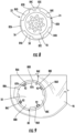
- the mask 10 also includes a frame 46 for coupling the nosecup 26, annular electronics housing 28, and voicemitter 22 to the facepiece 16.
- the frame 46 is located within the body 14 when the mask 10 is assembled, and the frame 46 includes at least one frame voicemitter aperture 50 and a portion for receiving the second nosecup stalk 44.
- the frame 46 includes a frame respirator receiving portion 52 that has an at least substantially semi-circular configuration, such that the frame 46 at least partially extends around, or is in contact with at least a portion of, the second nosecup stalk 44.
- the first nosecup stalk 40 extends through the frame voicemitter aperture 50 and the second nosecup stalk 44 extends through or is in contact with the semi-circular frame respirator receiving portion 52 of the frame 46.
- the voicemitter 22 is coupled to the frame 46 and at least partially extends within the frame voicemitter aperture 50.
- a voicemitter 22 head portion 56 is located within the nosecup first stalk 40 and at least a portion of a voicemitter neck portion 58 extends through a corresponding aperture 60 in the facepiece and extends through or is in contact with the frame voicemitter aperture 50.
- the first nosecup stalk 40 includes an inner diameter ID VMstalk that is greater than a diameter D VMaperture of the nosecup voicemitter aperture 34, such that the voicemitter 22 can be at least partially located within the first nosecup stalk 40 but cannot pass through the nosecup voicemitter aperture 34. For example, as shown in FIG.
- the diameter D head of the voicemitter head portion 56 is greater than the diameter D neck of the voicemitter neck portion 58, and the inner diameter D VMstalk of the first nosecup stalk 40 is approximately the same as (or slightly larger than) the diameter D head voicemitter head portion 56 and the diameter D VMaperture of the nosecup voicemitter aperture 34 is approximately the same as (or slightly larger than) the diameter D neck voicemitter neck portion 58 diameter.
- the voicemitter 22 is removably couplable to the frame 46 by rotation of the voicemitter 22 by a predetermined amount. In one embodiment, the voicemitter 22 is removably couplable by a quarter rotation of the voicemitter 22.
- the voicemitter 22 is removably couplable to the frame 46 by a less-than-full rotation, such as by an eighth rotation, a third rotation, half rotation, or any other rotation that is less than 360°.
- the voicemitter 22 is threaded on its outer surface and screws into the frame 46, the frame 46 having complementary threads to removably engage with the threads on the voicemitter 22.
- the second nosecup stalk 44 not only extends through or is contact with the semi-circular frame respirator receiving portion 52, but the second stalk 44 also extends through the annular electronics housing 28.
- the distal end 42 of the second nosecup stalk 44 includes a flange 62 that at least partially encircles the respirator aperture 36 of the second nosecup stalk 44.
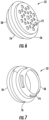
- the annular electronics housing 28 has a circular cross-sectional shape and an aperture 64 at its center. In some embodiments, the annular electronics housing 28 is flat on the top and/or bottom surfaces, thereby allowing for mating with adjacent flat surfaces of the mask 10.
- the annular electronics housing 28 is then coupled to the facepiece 16 and/or to the frame 46, such as with one or more screws, bolts, clasps, or other securing means. Additionally or alternatively, the annular electronics housing 28 may be rotatably couplable to the facepiece 16 and/or to the frame 46, such as by corresponding threading or other engagement feature(s) in the annular electronics housing aperture 64 and the facepiece respirator aperture 24 and/or the frame respirator receiving portion 52. When the annular electronics housing 28 is coupled to the mask 10, the nosecup is also secured to the mask 10. In an alternative embodiment, the annular electronics housing 28 is not coupled to the facepiece 16.
- the annular electronics housing 28 contains various electronics components, such as printed circuit boards, amplifiers, radio frequency components, processors, data storage units, transceivers, wireless communications units, or the like.
- the annular electronics housing 28 may also contain a power source 68 for providing power to the electronics components.
- the annular electronics housing 28 occupies the space within the mask that is usually occupied by a spacer, such as a spacer used to couple the nosecup 26 to the mask body 14.
- a spacer such as a spacer used to couple the nosecup 26 to the mask body 14.
- including the electronic components in the annular electronics housing 28 efficiently uses mask space, allowing the electronic components to be located in an otherwise wasted or unused space instead of the cheek areas of the mask, or in other areas where the electronic components would add bulk and possibly imbalance to the mask 10.
- the nosecup 26 is removably coupled to the mask 10 by the voicemitter(s) 22 only, the annular electronics housing 28 only, or both the voicemitter(s) 22 and the annular electronics housing 28.
- the frame 46 fits within and is coupled to the body 14 when the mask is assembled. Any components coupled to the frame 46 may also be coupled to the housing 14, or only to the frame 46.
- a cross-sectional view of the assembled mask 10 is shown in FIG. 5 .
- the mask 10 of FIG. 2 is shown and described as having one voicemitter 22, it will be understood that, in some embodiments, the mask 10 optionally includes two voicemitters 22, as shown and described in FIG. 4 .
- the nosecup 26 includes the first nosecup stalk 40 on a first side of the nosecup 26 and also includes a third nosecup stalk 70 on a second side of the nosecup 26 opposite the first side that has a second voicemitter aperture 34B (the voicemitter aperture of the first nosecup stalk 40 being the first voicemitter aperture 34A).
- the first nosecup stalk 40 is located a predetermined lateral distance from the second nosecup stalk 44 in a first direction and the third nosecup stalk 70 is located a predetermined lateral distance from the second nosecup stalk 44 in a second direction opposite the first direction.
- the second nosecup stalk 70 is sized and configured like the first nosecup stalk 40, including having a voicemitter aperture 34.
- the voicemitter 22 may also include a gasket 76 around at least a portion of the voicemitter neck portion 58 to provide an airtight seal between the voicemitter 22 and the frame 46 and/or other mask component to which the voicemitter 22 is attached.
- the neck portion 58 of the voicemitter 22 (or each voicemitter 22A, 22B if the mask includes two voicemitters) extends through the voicemitter aperture 34 of the nosecup 26 and through the frame voicemitter aperture 50.
- the neck portion 58 is couplable to the facepiece 16.
- the facepiece voicemitter aperture 60 may include engagement features 80 that are matable with the engagement features 74 on the voicemitter neck portion 58.
- the neck portion 58 is couplable to the frame 46 and/or the body 14.
- the frame 46, body 14, or both may include engagement features 80 that are matable with the engagement features 74 on the voicemitter neck portion 58, as is described in more detail below.
- the neck portion 58 is similarly couplable to both the facepiece 16 and the frame 46 and/or the body 14.
- the engagement features 74 on the voicemitter neck portion 58, and any corresponding engagement features 80 on the facepiece 16, frame 46, and/or body 14, are configured such that when the voicemitter 22 is positioned in matable contact with the engagement features of the facepiece 16, frame 46, and/or body 14, rotation of the voicemitter 22 by approximately 90° ( ⁇ 10°) couples and secures the voicemitter 22 to the frame 46 and/or other mask component to which the voicemitter 22 is attached (and no further rotation of the voicemitter 22 is possible).
- the same configuration of the engagement features 74 on the voicemitter neck portion 58, and any corresponding engagement features 80 on the facepiece 16, frame 46, and/or body 14, allows the voicemitter 22 to be uncoupled from the mask 10 by a rotation of as little as 90° ( ⁇ 10°) in a second direction opposite the first direction.
- the nosecup 26 is coupled to the body 14 by a quarter rotation of the voicemitter 22 within both the frame voicemitter aperture 50 and within the facepiece voicemitter aperture 60.
- each of the frame voicemitter aperture 50 and the facepiece voicemitter aperture 60 have complementary engagement features 80 to the engagement features 74 of the voicemitter 22.
- the frame voicemitter aperture 50 includes a first protrusion 86A, a second protrusion 86B diametrically opposite the first protrusion 86A, a third protrusion 86C on the circumference of the frame voicemitter aperture 50 centered between the first 84A and second 86B protrusions, and a fourth protrusion 86D diametrically opposite the third protrusion 86C.
- the first 86A, second 86B, third 86C, and fourth 86D protrusions have the same or approximately the same circumferential length.
- the frame voicemitter aperture 50 also includes a fifth 86E protrusion between the first 86A and fourth 86D protrusions.
- the fifth protrusion 86E is diametrically opposite the space 88B between the second 86B and third 86C protrusions.
- the fifth 86E protrusion, and the spaces between the fifth protrusion 84E and each of the first 86A and fourth 86D protrusions (88D and 88E, respectively), have the same or approximately the same circumferential length as one of the protrusions 86A-86D.
- the protrusions 86A-86E are collectively referred to as frame voicemitter aperture protrusions 86.
- each of the plurality of protrusions 86 is coplanar with the surface of the frame 46 in which the frame voicemitter aperture 50 lies.
- the first 86A, second 86B, third 86C, and fourth 86D protrusions may each have a ramped configuration.
- each of the first 86A, second 86B, third 86C, and fourth 86D protrusions may have a first end 87A and a second end 87B, with the first end 87A being closer to the voicemitter neck portion protrusions 82 when the voicemitter 22 is inserted into the frame voicemitter aperture 50.
- the second end 87B of the protrusions are ramped or canted toward the voicemitter neck portion protrusions 82 by approximately 5° ( ⁇ 2°).
- each of the first 86A, second 86B, third 86C, and fourth 86D protrusions may have at least one rotational stop feature 92 on the second end 87B.
- the voicemitter neck portion protrusions 82 may also include at least one corresponding stop feature. As is described in more detail below, this configuration of the frame voicemitter aperture protrusions 86 helps keep the voicemitter 22 locked to the frame 46.
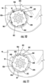
- FIG. 10 shows the voicemitter neck portion 58 positioned within the frame voicemitter aperture 50 such that the voicemitter 22 could be removed from the frame voicemitter aperture 50 without further rotation of the voicemitter 22.
- This may be referred to as the release position.
- the voicemitter neck portion protrusions 82 are aligned with the frame voicemitter aperture protrusion spaces 88.
- protrusion 82A is aligned with space 88A
- protrusion 82B is aligned with space 88C
- protrusion 82C is aligned with space 88B
- protrusion 82D is aligned with space 88D
- protrusion 82E is aligned with space 88E.
- protrusion 86A is aligned with space 84D
- protrusion 86B is aligned with space 84B
- protrusion 86C is aligned with space 84A
- protrusion 86D is aligned with space 84E
- protrusion 86E is aligned with space 84C.
- FIG. 11 shows the voicemitter neck portion 58 positioned within the frame voicemitter aperture 50 such that the voicemitter 22 is locked onto the frame 46 by the configuration of protrusions 82, 86 and spaces 84, 88 of the voicemitter 22 and frame voicemitter aperture 50. This may be referred to as the locked position.
- the voicemitter neck portion threading 74 is extended through the frame voicemitter aperture 50 so that subsequent rotation of the voicemitter 22 positions the protrusions 82 of the voicemitter on top of the protrusions 86 of the frame voicemitter aperture 50 (for example, as shown in FIG. 10 ).
- the ramped configuration of the frame voicemitter aperture protrusions 86 causes the voicemitter 22 to draw closer to, or tighten against, the frame 46 as the voicemitter 22 is rotated. Additionally, the at least one stop feature of the voicemitter neck portion protrusions 82 pass over are secured by the at least one rotational stop feature 92 of the frame voicemitter aperture protrusions 86.
- each of the first 86A, second 86B, third 86C, and fourth 86D frame voicemitter aperture protrusions includes two rotational stop features 92, and each of the first 82A, second 82B, and third 82C voicemitter neck portion protrusions includes one rotational stop feature.
- each voicemitter neck portion protrusion 82 is retained between the two rotational stop features 92 of the frame voicemitter aperture protrusions 86.
- This configuration prevents the voicemitter 22 from being disengaged from the frame 46.
- the protrusions 82, 86 are aligned and overlapping when the voicemitter 22 is rotated by an eighth rotation (that is, by rotation of 45°).
- the configuration of the protrusions 82, 86 allows the voicemitter 22 to be coupled to the frame 46 by a rotation of less than or more than an eighth rotation (for example, 45° ⁇ 15°). Further, the voicemitter 22 may pass from the release position to the locked position every eighth rotation.
- the voicemitter neck portion protrusions 82 and the frame voicemitter aperture protrusions 86 may be of any number and configuration that allows the voicemitter 22 to be quickly and easily coupled to the frame 46.
- the voicemitter neck portion 58 and the frame voicemitter aperture 50 include complementing protrusions 82, 86 that allow the voicemitter 22 to be coupled to the frame 46 by a quarter rotation (that is, rotation of approximately 90° ⁇ 15°) of the voicemitter neck portion 58 within the frame voicemitter aperture 50.
- a respirator mask 10 includes a frame 46 including a frame voicemitter aperture 50, a voicemitter 22, and a nosecup 26 removably coupled to the frame 46 by a rotation of the voicemitter 22 by a predetermined amount to removably lock the nosecup 26 to the frame voicemitter aperture 50.
- the voicemitter 22 includes a voicemitter head portion 56 and a voicemitter neck portion 58, at least a portion of the neck portion 58 being within the frame voicemitter aperture 50 when the nosecup 26 is locked to the frame voicemitter aperture 50.
- the nosecup 26 includes a first nosecup stalk 40 and a second nosecup stalk 44.
- the mask 10 further comprises a facepiece 16 having a respirator aperture 24, the second nosecup stalk 44 being configured to be in fluid communication with the respirator aperture 24.
- the voicemitter head portion 56 is located within the first nosecup stalk 40.
- the first nosecup stalk 40 includes a distal end 38 and a voicemitter aperture 34 at the first nosecup stalk distal end 38. In one aspect of the embodiment, at least a portion of the voicemitter neck portion 58 extends through the voicemitter aperture 34 of the first nosecup stalk 40. In one aspect of the embodiment, at least a portion of the voicemitter neck portion 58 is within the frame voicemitter aperture 50 when the mask 10 is assembled.
- the nosecup 26 is removably coupled to the mask 10 by a quarter turn of the voicemitter 22 within the frame voicemitter aperture 50 in a first direction, and the nosecup 26 is uncoupled from the mask 10 by a quarter turn of the voicemitter 22 within the frame voicemitter aperture 50 in a second direction opposite the first direction.
- the mask 10 further comprises an annular electronics housing 28.
- the annular electronics housing 28 includes an annular electronics housing aperture 64, the second nosecup stalk 44 extending through the annular electronics housing aperture 64 when the mask 10 is assembled.
- the frame 46 further includes a frame respirator receiving portion 52, the annular electronics housing 28 being rotatably couplable to the frame 46, the nosecup 26 being further removably coupled to the frame 46 when the annular electronics housing 28 is coupled to the frame 46.
- the second nosecup stalk 44 includes a distal end 42 and a respirator aperture 36 at the second nosecup stalk distal end 42, the second nosecup stalk 44 further including a flange 62 that at least partially encircles the second nosecup stalk respirator aperture 36.
- the flange 62 has a diameter and the annular electronics housing aperture 64 has an inner diameter, the diameter of the flange 62 being greater than the inner diameter of the annular electronics housing aperture 64 such that the flange 62 retains the annular electronics housing 28 to the second nosecup stalk 44.
- the nosecup 26 is removably coupled to the mask 10 by rotation of the voicemitter 22 within the frame voicemitter aperture 50 by the predetermined amount in a first direction, and the nosecup 26 is uncoupled from the mask 10 by rotation of the voicemitter 22 within the frame voicemitter aperture 50 by the predetermined amount in a second direction opposite the first direction, the nosecup 26 being uncoupled from the mask 10 when the annular electronics housing 28 is uncoupled from the frame 46 and the voicemitter 22 is rotated within the frame voicemitter aperture 50 by the predetermined amount in the second direction.
- the voicemitter 22 is a first voicemitter 22A on a first side of the mask 10, the mask further comprising a second voicemitter 22B on a second side of the mask 10 opposite the first side.
- the frame voicemitter aperture 50A is a first frame voicemitter aperture 50A and the frame further includes a second frame voicemitter aperture 50B
- the nosecup 26 includes: a first nosecup stalk 40; a second nosecup stalk 44; and a third nosecup stalk 70
- each of the first voicemitter 22A and the second voicemitter 22B including a voicemitter head portion 56 and a voicemitter neck portion 58, at least a portion of the neck portion 58 of the first voicemitter 22A being within the first frame voicemitter aperture 50A and at least a portion of the neck portion 58 of the second voicemitter 22B being within the second frame voicemitter aperture 50B when the mask 10 is assembled.
- the nosecup 26 is removably coupled to the mask 10 by rotation of the first voicemitter 22A within the first frame voicemitter aperture 50A by the predetermined amount in a first direction and a rotation of the second voicemitter 22B within the second frame voicemitter aperture 50B by the predetermined amount in the first direction, and the nosecup 26 is uncoupled from the mask 10 by rotation of the first voicemitter 22A within the first frame voicemitter aperture 50A by the predetermined amount in a second direction opposite the first direction and of the second voicemitter 22B within the second frame voicemitter aperture 50B by the predetermined amount in the second direction.
- the frame voicemitter aperture 50 of the frame 46 is a first frame voicemitter aperture 50A and the frame further includes a second frame voicemitter aperture 50B and a semi-circular frame respirator receiving portion 52 between the first 50A and second 50B frame voicemitter apertures;
- the voicemitter 22 is a first voicemitter 22A and the respirator mask 10 further comprises a second voicemitter 22B, each of the first 22A and second 22B voicemitters having a head portion 56 and a neck portion 58;
- the nosecup 26 includes a first nosecup stalk 40 with a first nosecup voicemitter aperture 34A, a second nosecup stalk 44 with a respirator aperture 36, and a third nosecup stalk 70 with a second nosecup voicemitter aperture 34B, the head portion 56 of the first voicemitter 22A being within the first nosecup stalk 40 and at least a portion of the neck portion 58 of the first voicemitter 22A extending through the first nosecup voicemitter aperture 34A and the first frame voicemitter aperture 50
- the voicemitter 22 is a first voicemitter 22A and the respirator mask 10 further comprises a second voicemitter 22B; and the nosecup 26 includes: a first nosecup stalk 40 having a first nosecup voicemitter aperture 34A; a second nosecup stalk 44 having a respirator aperture 36; a third nosecup stalk 70 having a second nosecup voicemitter aperture 34B, each of the first 40 and third 70 nosecup stalks being configured to receive at least a portion of a voicemitter 22A, 22B, the nosecup 26 being configured to be removably coupled to a frame 46 of the mask 10 by a rotation of the first 22A and second 22B voicemitters within the first 40 and third 70 nosecup stalks by a predetermined amount in a first direction and uncoupled from the mask 10 by a rotation of the first 22A and second 22B voicemitters within the first 40 third 70 nosecup stalks by the predetermined amount in a second direction opposite the first direction.
Landscapes
- Health & Medical Sciences (AREA)
- General Health & Medical Sciences (AREA)
- Pulmonology (AREA)
- Business, Economics & Management (AREA)
- Emergency Management (AREA)
- Life Sciences & Earth Sciences (AREA)
- Zoology (AREA)
- Engineering & Computer Science (AREA)
- Physical Education & Sports Medicine (AREA)
- Textile Engineering (AREA)
- Respiratory Apparatuses And Protective Means (AREA)
- Battery Mounting, Suspending (AREA)
- Chemical & Material Sciences (AREA)
- Chemical Kinetics & Catalysis (AREA)
- Electrochemistry (AREA)
- General Chemical & Material Sciences (AREA)
Applications Claiming Priority (2)
| Application Number | Priority Date | Filing Date | Title |
|---|---|---|---|
| US201662322936P | 2016-04-15 | 2016-04-15 | |
| PCT/US2017/027700 WO2017181064A2 (en) | 2016-04-15 | 2017-04-14 | Facemask nosecup retained by voicemitters |
Publications (2)
| Publication Number | Publication Date |
|---|---|
| EP3442667A2 EP3442667A2 (en) | 2019-02-20 |
| EP3442667B1 true EP3442667B1 (en) | 2025-03-05 |
Family
ID=58606608
Family Applications (3)
| Application Number | Title | Priority Date | Filing Date |
|---|---|---|---|
| EP17733102.2A Active EP3442667B1 (en) | 2016-04-15 | 2017-04-14 | Facemask nosecup retained by voicemitters |
| EP17718797.8A Withdrawn EP3442665A1 (en) | 2016-04-15 | 2017-04-14 | Headgear for first responders |
| EP17733094.1A Active EP3442666B1 (en) | 2016-04-15 | 2017-04-14 | Removable battery cartridge for facemask |
Family Applications After (2)
| Application Number | Title | Priority Date | Filing Date |
|---|---|---|---|
| EP17718797.8A Withdrawn EP3442665A1 (en) | 2016-04-15 | 2017-04-14 | Headgear for first responders |
| EP17733094.1A Active EP3442666B1 (en) | 2016-04-15 | 2017-04-14 | Removable battery cartridge for facemask |
Country Status (9)
Families Citing this family (17)
| Publication number | Priority date | Publication date | Assignee | Title |
|---|---|---|---|---|
| TWI780489B (zh) | 2014-09-16 | 2022-10-11 | 紐西蘭商費雪 & 佩凱爾關心健康有限公司 | 模內成型頭帽 |
| CN113398410A (zh) | 2014-09-16 | 2021-09-17 | 费雪派克医疗保健有限公司 | 头帽组件和具有头帽的接口组件 |
| USD986409S1 (en) * | 2015-07-14 | 2023-05-16 | CleanSpace IP Pty Ltd | Breathing apparatus |
| SG10202009031VA (en) | 2016-03-16 | 2020-10-29 | Fisher & Paykel Healthcare Ltd | Intra-mould substrate |
| CN115212417A (zh) | 2016-03-16 | 2022-10-21 | 费雪派克医疗保健有限公司 | 绑带组件 |
| CA3021089A1 (en) | 2016-04-15 | 2017-10-19 | Scott Technologies, Inc. | Removable battery cartridge for facemask |
| US11857032B1 (en) * | 2017-08-20 | 2024-01-02 | Team Nexbelt Operating, Inc. | Belt buckle system with threaded retainers |
| AU201811801S (en) * | 2017-10-02 | 2018-04-16 | Jsp Ltd | Full face mask respirator |
| GB2575233A (en) * | 2018-04-24 | 2020-01-08 | Anthony Griffiths Joseph | A breathing apparatus |
| EP3863730B1 (en) | 2018-10-12 | 2025-09-10 | 3M Innovative Properties Company | Scba facemask assembly with accelerometer to extend battery life of electrical components |
| WO2020229939A1 (en) * | 2019-05-10 | 2020-11-19 | 3M Innovative Properties Company | Facepiece chin retention feature |
| KR20220080115A (ko) | 2019-10-04 | 2022-06-14 | 쓰리엠 이노베이티브 프로퍼티즈 캄파니 | 호흡 보호 장치를 위한 무선 통신 특징부 |
| US12017232B2 (en) | 2020-03-13 | 2024-06-25 | Julian HENLEY | Electro-ionic mask devices for improved protection from airborne biopathogens |
| WO2021184011A1 (en) | 2020-03-13 | 2021-09-16 | Henley Julian | Electro-ionic devices for improved protection from airborne biopathogens |
| US11612197B2 (en) * | 2020-04-03 | 2023-03-28 | Rory Korathu-Larson, LLC | Apparatus with fastenerless connection between components and assembly method thereof |
| KR102185275B1 (ko) * | 2020-06-18 | 2020-12-01 | 윤흥수 | 마스크용 호흡기 |
| SE547034C2 (en) * | 2023-03-22 | 2025-04-08 | Tiki Safety Ab | A powered air purifying respirator comprising a full face mask and a power source unit fixed thereto |
Family Cites Families (63)
| Publication number | Priority date | Publication date | Assignee | Title |
|---|---|---|---|---|
| US3238535A (en) * | 1963-11-04 | 1966-03-08 | Richey Willie Hugh | Welding helmet |
| JPS585455U (ja) * | 1981-07-02 | 1983-01-13 | 株式会社マルナカ | 呼吸マスク |
| JPS5997678A (ja) * | 1982-11-27 | 1984-06-05 | 塩田 真三 | 防煙マスク |
| US4595003A (en) | 1983-10-21 | 1986-06-17 | The United States Of America As Represented By The Secretary Of The Army | Protective mask for airborne toxic substances |
| US5060308A (en) * | 1989-01-23 | 1991-10-22 | Bieback John S | Firefighters mask communication system |
| US5031237A (en) | 1989-12-05 | 1991-07-16 | Honrud Gregory S | Light actuated air recirculating and filtration system |
| US5224473A (en) * | 1991-03-04 | 1993-07-06 | Bloomfield John W | Retrofitting gas mask voice amplifier unit with easily actuated switch means |
| FR2695039B1 (fr) | 1992-09-01 | 1995-06-16 | Peron Jean Yves | Dispositif de communication adapte a un ensemble respiratoire. |
| EP0722352B1 (en) * | 1993-10-01 | 2000-05-03 | Minnesota Mining And Manufacturing Company | Speech transmission adaptor for use with a respirator mask |
| US6121881A (en) * | 1994-09-02 | 2000-09-19 | Safety Tech Industries, Inc. | Protective mask communication devices and systems for use in hazardous environments |
| FR2764517B1 (fr) * | 1997-06-17 | 1999-09-03 | App De Protection Soc Nouv | Dispositif pour l'assistance respiratoire d'un malade |
| CN2321479Y (zh) * | 1997-06-26 | 1999-06-02 | 徐永红 | 一种防尘口罩 |
| US5934762A (en) | 1997-08-08 | 1999-08-10 | Remedent Usa, Inc. | Oral hygiene devices and manufacturing methods therefor |
| US6168881B1 (en) * | 1998-08-14 | 2001-01-02 | S-B Power Tool Company | Latch mechanism for a battery operated power tool |
| CN2346461Y (zh) * | 1998-11-12 | 1999-11-03 | 陈天明 | 防尘防毒口鼻罩 |
| US6895960B2 (en) | 2001-01-18 | 2005-05-24 | 3M Innovative Properties Company | Modular respirators and a method of conversion thereof |
| KR100919332B1 (ko) | 2001-07-24 | 2009-09-25 | 소니 가부시끼 가이샤 | 배터리 장치 |
| JP3925120B2 (ja) * | 2001-07-24 | 2007-06-06 | ソニー株式会社 | 本体側機器に対する装着部品の誤装着防止方法およびこれに用いられる装着部品 |
| CN2544759Y (zh) * | 2002-05-27 | 2003-04-16 | 诚加兴业股份有限公司 | 游泳面罩的带扣结构 |
| US6899101B2 (en) * | 2002-06-24 | 2005-05-31 | Survivair Respirators, Inc. | Logical display for a breathing apparatus mask |
| CN2561454Y (zh) * | 2002-06-28 | 2003-07-23 | 诚加兴业股份有限公司 | 游泳面罩的带扣结构 |
| KR200335505Y1 (ko) * | 2003-09-18 | 2003-12-06 | 주식회사 산청 | 방독면 전성배기유닛 |
| JP2006102324A (ja) * | 2004-10-07 | 2006-04-20 | Shigematsu Works Co Ltd | 電動ファン付呼吸用保護具 |
| US7805816B1 (en) * | 2005-11-28 | 2010-10-05 | Allan Thorne, III | Cargo strap |
| US7448386B2 (en) * | 2005-12-07 | 2008-11-11 | Ric Investments, Llc | Full face respiratory mask with integrated nasal interface |
| CN201042027Y (zh) * | 2007-04-11 | 2008-03-26 | 深圳市好易通科技有限公司 | 电池闩锁结构 |
| JP5171106B2 (ja) * | 2007-05-21 | 2013-03-27 | 三洋電機株式会社 | 電池パック、電池パックを装着可能な電気機器及びラッチ構造体 |
| BRPI0819440B8 (pt) | 2007-11-14 | 2023-01-31 | Ric Investments Llc | conjunto de máscara, e, kit de conjunto de máscara |
| KR20100105607A (ko) * | 2007-11-20 | 2010-09-29 | 애번 프로텍션 시스템 인코포레이티드 | 모듈식 전동 공기 정화 호흡보호구 |
| US20100132721A1 (en) | 2008-12-02 | 2010-06-03 | Rpb, Ltd. | Respirator helmet with integrated hearing protection |
| KR101696651B1 (ko) * | 2009-02-23 | 2017-01-17 | 애버리 데니슨 코포레이션 | 케이블 타이 |
| US8905018B2 (en) * | 2009-10-07 | 2014-12-09 | Shigematsu Works Co., Ltd. | Breathing apparatus |
| JP5305401B2 (ja) * | 2009-10-07 | 2013-10-02 | 株式会社重松製作所 | 呼吸装置 |
| US20110100370A1 (en) * | 2009-10-29 | 2011-05-05 | Moldex-Metric, Inc. | Overmolding buckles at the same time as overmolding a lens respirator |
| JP5218444B2 (ja) * | 2010-02-12 | 2013-06-26 | 富士通株式会社 | 情報処理装置及び着脱ユニット |
| GB2478759A (en) | 2010-03-17 | 2011-09-21 | 3M Innovative Properties Co | A powered air purifying respirator |
| SE534951C2 (sv) | 2010-06-18 | 2012-02-28 | Facecover Sweden Ab | Motordriven luftrenande respirator (PAPR) |
| EP3718604B1 (en) * | 2010-07-02 | 2024-04-24 | MSA Technology, LLC | Data communication and displays for breathing apparatus facepieces and pressure regulators |
| US20120125341A1 (en) * | 2010-11-19 | 2012-05-24 | 3M Innovative Properties Company | Filtering face-piece respirator having an overmolded face seal |
| JP5592908B2 (ja) * | 2012-02-23 | 2014-09-17 | 興研株式会社 | 呼吸用保護具 |
| US9457164B2 (en) | 2012-04-02 | 2016-10-04 | Tracoe Medical Gmbh | Insert for tracheostomy tube neck straps |
| CN102772858A (zh) * | 2012-07-11 | 2012-11-14 | 孔静 | 一种面膜 |
| SG10201700946YA (en) | 2012-08-08 | 2017-03-30 | Fisher & Paykel Healthcare Ltd | Headgear for patient interface |
| WO2014070770A1 (en) | 2012-11-01 | 2014-05-08 | Abominable Labs, Llc | Goggle with battery pods |
| CN203087593U (zh) * | 2013-01-05 | 2013-07-31 | 宋令清 | 通讯面罩 |
| US9498658B2 (en) * | 2013-02-01 | 2016-11-22 | 3M Innovative Properties Company | Respirator mask speech enhancement apparatus and method |
| US9510626B2 (en) * | 2013-02-01 | 2016-12-06 | 3M Innovative Properties Company | Sleeve-fit respirator cartridge |
| JP5782472B2 (ja) * | 2013-03-12 | 2015-09-24 | レノボ・シンガポール・プライベート・リミテッド | 電子機器 |
| RU2668855C2 (ru) * | 2013-03-15 | 2018-10-03 | Скотт Текнолоджиз, Инк. | Полнолицевая маска с перестраиваемой структурой, содержащая картридж-модуль для защиты органов дыхания |
| US10095833B2 (en) | 2013-09-22 | 2018-10-09 | Ricoh Co., Ltd. | Mobile information gateway for use by medical personnel |
| US20150084235A1 (en) * | 2013-09-26 | 2015-03-26 | Moldex-Metric, Inc. | Overmolding buckles at the same time as overmolding a lens respirator |
| EP3036722A1 (en) | 2013-10-17 | 2016-06-29 | ADT US Holdings, Inc. | Portable system for managing events |
| WO2015084255A1 (en) | 2013-12-04 | 2015-06-11 | Singapore Technologies Dynamics Pte Ltd | An active venting system and devices incorporating active venting system |
| JP6234844B2 (ja) * | 2014-03-06 | 2017-11-22 | 興研株式会社 | 防護マスク用のシール具 |
| JP2015191735A (ja) * | 2014-03-27 | 2015-11-02 | 日立工機株式会社 | 電池パック、電動工具、及び充電器 |
| US10142669B2 (en) * | 2014-04-08 | 2018-11-27 | The Swatch Group Research And Development Ltd | System of connected devices |
| KR20150122409A (ko) * | 2014-04-23 | 2015-11-02 | 주식회사 엘지화학 | Pcb 접합 방법 |
| KR101460942B1 (ko) * | 2014-04-29 | 2014-11-13 | 임미영 | 마스크 |
| SE538397C2 (sv) | 2014-04-30 | 2016-06-14 | Monivent Ab | Återupplivningsanordning och metod för parameterövervakningi en återupplivningsanordning |
| TWM494468U (zh) * | 2014-08-13 | 2015-01-21 | Wistron Corp | 電池退出結構 |
| CN205108058U (zh) * | 2015-04-22 | 2016-03-30 | 泰克曼(南京)电子有限公司 | 锁扣配合结构以及电动空气净化呼吸器 |
| GB2541672B (en) | 2015-08-25 | 2019-12-11 | Jsp Ltd | A powered air respirator kit |
| CA3021089A1 (en) | 2016-04-15 | 2017-10-19 | Scott Technologies, Inc. | Removable battery cartridge for facemask |
-
2017
- 2017-04-14 CA CA3021089A patent/CA3021089A1/en active Pending
- 2017-04-14 AU AU2017248738A patent/AU2017248738B2/en active Active
- 2017-04-14 CN CN201780030008.4A patent/CN109789322A/zh active Pending
- 2017-04-14 EP EP17733102.2A patent/EP3442667B1/en active Active
- 2017-04-14 US US16/093,296 patent/US10926114B2/en active Active
- 2017-04-14 BR BR112018071222-1A patent/BR112018071222B1/pt active IP Right Grant
- 2017-04-14 KR KR1020187032975A patent/KR20180133908A/ko not_active Ceased
- 2017-04-14 CN CN201780032803.7A patent/CN109562285B/zh active Active
- 2017-04-14 AU AU2017248735A patent/AU2017248735B2/en not_active Ceased
- 2017-04-14 WO PCT/US2017/027547 patent/WO2017180951A2/en active Application Filing
- 2017-04-14 KR KR1020187032836A patent/KR102492537B1/ko active Active
- 2017-04-14 BR BR112018071223A patent/BR112018071223A2/pt not_active Application Discontinuation
- 2017-04-14 WO PCT/US2017/027534 patent/WO2017180940A1/en active Application Filing
- 2017-04-14 WO PCT/US2017/027700 patent/WO2017181064A2/en active Application Filing
- 2017-04-14 US US16/093,362 patent/US10946223B2/en active Active
- 2017-04-14 EP EP17718797.8A patent/EP3442665A1/en not_active Withdrawn
- 2017-04-14 EP EP17733094.1A patent/EP3442666B1/en active Active
- 2017-04-14 CN CN201780032775.9A patent/CN109475761A/zh active Pending
- 2017-04-14 CA CA3021088A patent/CA3021088A1/en active Pending
- 2017-04-14 JP JP2018554405A patent/JP2019511333A/ja active Pending
- 2017-04-14 US US16/093,344 patent/US20190118009A1/en not_active Abandoned
- 2017-04-14 JP JP2018554365A patent/JP2019511330A/ja active Pending
- 2017-04-14 KR KR1020187032835A patent/KR20180134981A/ko not_active Ceased
-
2022
- 2022-03-02 JP JP2022031959A patent/JP2022079475A/ja not_active Withdrawn
- 2022-05-11 JP JP2022078147A patent/JP7661274B2/ja active Active
Also Published As
Similar Documents
| Publication | Publication Date | Title |
|---|---|---|
| EP3442667B1 (en) | Facemask nosecup retained by voicemitters | |
| US10661104B2 (en) | Reconfigurable full facemask having a cartridge module for respiratory protection | |
| US11547878B2 (en) | Respirators | |
| EP0728403B1 (en) | Voice transmission adaptor assembly | |
| US6854464B2 (en) | Respiration protecting apparatus | |
| EP0957993B1 (en) | Full face respirator mask having integral connectors disposed in lens area | |
| US9833644B2 (en) | Air purification respirator voice amplifier | |
| CN212395645U (zh) | 全面罩呼吸器、口鼻罩组件和全面罩呼吸器部件套装 | |
| CA2751207C (en) | Respirator kit and contoured plenum therefor | |
| US9560459B2 (en) | Modular voice amplification system for protective mask | |
| CN114502242A (zh) | 用于呼吸保护装置的无线通信特征 | |
| US20250114650A1 (en) | A platform for respiratory protective equipment | |
| US20240342514A1 (en) | Modular full-face respirator |
Legal Events
| Date | Code | Title | Description |
|---|---|---|---|
| STAA | Information on the status of an ep patent application or granted ep patent |
Free format text: STATUS: UNKNOWN |
|
| STAA | Information on the status of an ep patent application or granted ep patent |
Free format text: STATUS: THE INTERNATIONAL PUBLICATION HAS BEEN MADE |
|
| PUAI | Public reference made under article 153(3) epc to a published international application that has entered the european phase |
Free format text: ORIGINAL CODE: 0009012 |
|
| STAA | Information on the status of an ep patent application or granted ep patent |
Free format text: STATUS: REQUEST FOR EXAMINATION WAS MADE |
|
| 17P | Request for examination filed |
Effective date: 20181029 |
|
| AK | Designated contracting states |
Kind code of ref document: A2 Designated state(s): AL AT BE BG CH CY CZ DE DK EE ES FI FR GB GR HR HU IE IS IT LI LT LU LV MC MK MT NL NO PL PT RO RS SE SI SK SM TR |
|
| AX | Request for extension of the european patent |
Extension state: BA ME |
|
| DAV | Request for validation of the european patent (deleted) | ||
| DAX | Request for extension of the european patent (deleted) | ||
| STAA | Information on the status of an ep patent application or granted ep patent |
Free format text: STATUS: EXAMINATION IS IN PROGRESS |
|
| 17Q | First examination report despatched |
Effective date: 20191105 |
|
| GRAP | Despatch of communication of intention to grant a patent |
Free format text: ORIGINAL CODE: EPIDOSNIGR1 |
|
| STAA | Information on the status of an ep patent application or granted ep patent |
Free format text: STATUS: GRANT OF PATENT IS INTENDED |
|
| INTG | Intention to grant announced |
Effective date: 20241010 |
|
| P01 | Opt-out of the competence of the unified patent court (upc) registered |
Free format text: CASE NUMBER: APP_60986/2024 Effective date: 20241113 |
|
| GRAS | Grant fee paid |
Free format text: ORIGINAL CODE: EPIDOSNIGR3 |
|
| GRAA | (expected) grant |
Free format text: ORIGINAL CODE: 0009210 |
|
| STAA | Information on the status of an ep patent application or granted ep patent |
Free format text: STATUS: THE PATENT HAS BEEN GRANTED |
|
| AK | Designated contracting states |
Kind code of ref document: B1 Designated state(s): AL AT BE BG CH CY CZ DE DK EE ES FI FR GB GR HR HU IE IS IT LI LT LU LV MC MK MT NL NO PL PT RO RS SE SI SK SM TR |
|
| REG | Reference to a national code |
Ref country code: GB Ref legal event code: FG4D |
|
| REG | Reference to a national code |
Ref country code: CH Ref legal event code: EP |
|
| REG | Reference to a national code |
Ref country code: IE Ref legal event code: FG4D |
|
| REG | Reference to a national code |
Ref country code: DE Ref legal event code: R096 Ref document number: 602017088159 Country of ref document: DE |
|
| PG25 | Lapsed in a contracting state [announced via postgrant information from national office to epo] |
Ref country code: RS Free format text: LAPSE BECAUSE OF FAILURE TO SUBMIT A TRANSLATION OF THE DESCRIPTION OR TO PAY THE FEE WITHIN THE PRESCRIBED TIME-LIMIT Effective date: 20250605 |
|
| PG25 | Lapsed in a contracting state [announced via postgrant information from national office to epo] |
Ref country code: FI Free format text: LAPSE BECAUSE OF FAILURE TO SUBMIT A TRANSLATION OF THE DESCRIPTION OR TO PAY THE FEE WITHIN THE PRESCRIBED TIME-LIMIT Effective date: 20250305 |
|
| PGFP | Annual fee paid to national office [announced via postgrant information from national office to epo] |
Ref country code: DE Payment date: 20250319 Year of fee payment: 9 |
|
| REG | Reference to a national code |
Ref country code: NL Ref legal event code: MP Effective date: 20250305 |
|
| PG25 | Lapsed in a contracting state [announced via postgrant information from national office to epo] |
Ref country code: ES Free format text: LAPSE BECAUSE OF FAILURE TO SUBMIT A TRANSLATION OF THE DESCRIPTION OR TO PAY THE FEE WITHIN THE PRESCRIBED TIME-LIMIT Effective date: 20250305 |
|
| PGFP | Annual fee paid to national office [announced via postgrant information from national office to epo] |
Ref country code: GB Payment date: 20250423 Year of fee payment: 9 |
|
| REG | Reference to a national code |
Ref country code: LT Ref legal event code: MG9D |
|
| PG25 | Lapsed in a contracting state [announced via postgrant information from national office to epo] |
Ref country code: NO Free format text: LAPSE BECAUSE OF FAILURE TO SUBMIT A TRANSLATION OF THE DESCRIPTION OR TO PAY THE FEE WITHIN THE PRESCRIBED TIME-LIMIT Effective date: 20250605 |
|
| PG25 | Lapsed in a contracting state [announced via postgrant information from national office to epo] |
Ref country code: HR Free format text: LAPSE BECAUSE OF FAILURE TO SUBMIT A TRANSLATION OF THE DESCRIPTION OR TO PAY THE FEE WITHIN THE PRESCRIBED TIME-LIMIT Effective date: 20250305 |
|
| PG25 | Lapsed in a contracting state [announced via postgrant information from national office to epo] |
Ref country code: LV Free format text: LAPSE BECAUSE OF FAILURE TO SUBMIT A TRANSLATION OF THE DESCRIPTION OR TO PAY THE FEE WITHIN THE PRESCRIBED TIME-LIMIT Effective date: 20250305 |
|
| PG25 | Lapsed in a contracting state [announced via postgrant information from national office to epo] |
Ref country code: BG Free format text: LAPSE BECAUSE OF FAILURE TO SUBMIT A TRANSLATION OF THE DESCRIPTION OR TO PAY THE FEE WITHIN THE PRESCRIBED TIME-LIMIT Effective date: 20250305 Ref country code: GR Free format text: LAPSE BECAUSE OF FAILURE TO SUBMIT A TRANSLATION OF THE DESCRIPTION OR TO PAY THE FEE WITHIN THE PRESCRIBED TIME-LIMIT Effective date: 20250606 |
|
| REG | Reference to a national code |
Ref country code: AT Ref legal event code: MK05 Ref document number: 1772401 Country of ref document: AT Kind code of ref document: T Effective date: 20250305 |
|
| PG25 | Lapsed in a contracting state [announced via postgrant information from national office to epo] |
Ref country code: NL Free format text: LAPSE BECAUSE OF FAILURE TO SUBMIT A TRANSLATION OF THE DESCRIPTION OR TO PAY THE FEE WITHIN THE PRESCRIBED TIME-LIMIT Effective date: 20250305 |