EP3439093B1 - Redox-flow-batterie und verfahren zum betreiben einer redox-flow-batterie - Google Patents
Redox-flow-batterie und verfahren zum betreiben einer redox-flow-batterie Download PDFInfo
- Publication number
- EP3439093B1 EP3439093B1 EP17275122.4A EP17275122A EP3439093B1 EP 3439093 B1 EP3439093 B1 EP 3439093B1 EP 17275122 A EP17275122 A EP 17275122A EP 3439093 B1 EP3439093 B1 EP 3439093B1
- Authority
- EP
- European Patent Office
- Prior art keywords
- anode
- redox flow
- chamber
- flow battery
- cathode
- Prior art date
- Legal status (The legal status is an assumption and is not a legal conclusion. Google has not performed a legal analysis and makes no representation as to the accuracy of the status listed.)
- Active
Links
Images


Classifications
-
- H—ELECTRICITY
- H01—ELECTRIC ELEMENTS
- H01M—PROCESSES OR MEANS, e.g. BATTERIES, FOR THE DIRECT CONVERSION OF CHEMICAL ENERGY INTO ELECTRICAL ENERGY
- H01M8/00—Fuel cells; Manufacture thereof
- H01M8/18—Regenerative fuel cells, e.g. redox flow batteries or secondary fuel cells
- H01M8/184—Regeneration by electrochemical means
- H01M8/188—Regeneration by electrochemical means by recharging of redox couples containing fluids; Redox flow type batteries
-
- H—ELECTRICITY
- H01—ELECTRIC ELEMENTS
- H01M—PROCESSES OR MEANS, e.g. BATTERIES, FOR THE DIRECT CONVERSION OF CHEMICAL ENERGY INTO ELECTRICAL ENERGY
- H01M4/00—Electrodes
- H01M4/02—Electrodes composed of, or comprising, active material
-
- H—ELECTRICITY
- H01—ELECTRIC ELEMENTS
- H01M—PROCESSES OR MEANS, e.g. BATTERIES, FOR THE DIRECT CONVERSION OF CHEMICAL ENERGY INTO ELECTRICAL ENERGY
- H01M4/00—Electrodes
- H01M4/02—Electrodes composed of, or comprising, active material
- H01M4/04—Processes of manufacture in general
-
- H—ELECTRICITY
- H01—ELECTRIC ELEMENTS
- H01M—PROCESSES OR MEANS, e.g. BATTERIES, FOR THE DIRECT CONVERSION OF CHEMICAL ENERGY INTO ELECTRICAL ENERGY
- H01M4/00—Electrodes
- H01M4/02—Electrodes composed of, or comprising, active material
- H01M2004/021—Physical characteristics, e.g. porosity, surface area
Definitions
- the invention relates to a redox flow battery and a method for operating a redox flow battery.
- Batteries are stores for electrical energy on an electrochemical basis and are suitable for storing the excess energy. If it is a rechargeable memory, this is also called an accumulator.
- a single rechargeable storage element is also called a secondary element.
- redox flow batteries In contrast to classic secondary elements, redox flow batteries have a liquid electrode active material.
- This liquid electrolyte is stored in a tank and pumped into a cathode compartment with a cathode and / or into an anode compartment with an anode.
- the liquid electrolyte therefore advantageously comprises a reduction-oxidation pair as the electrode-active material.
- the electrode-active material on the electrodes is reduced or oxidized.
- the electrodes typically include graphite or carbon.
- the structure of the electrodes is typical porous in the form of a fleece or a fur, or in other words in the form of a grid or structural element, in order to provide the largest possible surface area of the electrodes.
- the hydrogen evolution reaction (HER) disadvantageously takes place on these electrodes. This leads disadvantageously to the fact that there are unequal charge ratios between the anolyte and the catholyte. The disadvantage is that Faraday's efficiency is significantly reduced.
- the object is achieved by means of an electrically rechargeable redox flow battery according to claim 1 and a method for operating a redox flow battery according to claim 10.
- an electrically rechargeable redox flow battery comprises a first chamber and a second chamber.
- the first chamber is separated from the second chamber by means of a membrane.
- the first chamber comprises a cathode and the second chamber comprises an anode.
- a first planar surface of the cathode and / or a second planar surface of the anode has elevations to enlarge the surface.
- a redox flow battery is provided with a first chamber and a second chamber.
- the first chamber is separated from the second chamber by means of a membrane.
- the first chamber comprises a cathode and the second chamber comprises an anode.
- a first surface of the cathode and / or a second surface of the anode has elevations for increasing the surface. These elevations are suitable for forming flow channels for a first and / or second electrolyte of the redox flow battery.
- the cathode and / or the anode comprise at least a first material, the first material comprising lead or bismuth.
- a first electrolyte is fed into the first chamber and a second electrolyte is fed into the second chamber.
- the redox flow battery is then charged or discharged in the two chambers.
- the cathode and / or the anode are essentially planar. Elevations are arranged on the cathode and / or the anode. Elevations are understood here to mean structured elevations, in particular in the form of cylindrical, cube-shaped, pyramid-shaped or hemispherical elevations. Flow channels are formed between the elevations, through which the first and / or second electrolyte can flow.
- the materials lead or bismuth used according to the invention have a higher overvoltage potential compared to the development of hydrogen than conventional carbon or graphite electrodes.
- the overvoltage potential compared to hydrogen at 25 ° C is less than - 0.6 V.
- the electrical potential applied to the anode can be more negative than with carbon or graphite electrodes, which advantageously means more electrons per molecule of the reduction-oxidation pair of the Anode can be transferred to the cathode.
- the electrical current is thus efficiently transferred to a reduction-oxidation pair in the electrolyte by reducing or oxidizing it.
- the hydrogen formation reaction competing for this reaction is significantly reduced.
- a divergence of the first electrolyte, ie the catholyte, and the second electrolyte, ie the anolyte is avoided with regard to the pH.
- the changed pH value damages the polyoxometalates, especially in the anolyte, due to the use of a proton in the evolution of hydrogen.
- the redox flow battery can advantageously be operated for a long time if the hydrogen formation reaction is reduced without the first and / or second electrolyte having to be exchanged.
- the cathode and / or anode comprises lead or bismuth as the first material.
- These materials may be with organic oxidation-reduction pairs on quinone-based, in particular AQDSH 2 / AQDS (AQDS means 9, 10 anthraquinone-2,7-disulfonic acid) and are used Br 2/2 HBr.
- lead or bismuth as the electrode material with organic reduction-oxidation pairs based on polymers, in particular polymers based on TEMPO / TEMPO + (TEMPO means 2,2,6,6-tetramethylpiperidinyloxyl) and based on viologens, in other words, N 'dialkyl-4,4'-bipyridines (Viol2 - / Viol + ).
- TEMPO means 2,2,6,6-tetramethylpiperidinyloxyl
- viologens in other words, N 'dialkyl-4,4'-bipyridines (Viol2 - / Viol + ).
- Lead and bismuth are particularly advantageous and are not expensive compared to other materials.
- the elevations have a first long side and a second short side.
- the elevations are therefore essentially rectangular.
- the elevations are in particular arranged parallel or in a meandering shape. In the case of the parallel arrangement, parallel flow channels are created, as a result of which the first and / or second electrolyte is led through the redox flow battery through a plurality of individual flow channels.
- the redox flow battery results in a long flow channel.
- the first material comprises lead or bismuth with a weight fraction of at least 20%, in particular at least 40%.
- Lead or bismuth are therefore not only contained in the electrodes to a small extent, in particular as impurities, but also represent an essential material of the electrodes. This advantageously guarantees that the overvoltage potential with respect to hydrogen is so low that no or almost no hydrogen in the Redox flow battery is produced.
- the cathode and / or the anode at least partially touch the membrane directly.
- the flow direction of the first and / or second electrolyte in the redox flow battery is thus advantageously predetermined.
- the contact area which the first and / or second electrolyte has with the electrodes can advantageously be defined.
- the cathode and / or the anode comprises a second material, the second material comprising polymer fibers or carbon fibers.
- the fibers advantageously stabilize the respective shape of the anode and / or cathode.
- expensive material is replaced by cheaper fiber material. This advantageously lowers the manufacturing cost of the electrode.
- a proportion by weight of the second material is at least 10%, particularly advantageously at least 15%.
- the first material is arranged as a layer on the second material.
- the production costs are advantageously kept as low as possible since the production of the second material is cheaper and a sufficiently thick layer of the first material has the required overvoltage potential compared to hydrogen.
- the thickness of the layer is preferably in a range from 3 ⁇ m and 50 ⁇ m, particularly preferably in a range from 5 ⁇ m to 20 ⁇ m.
- the anode and / or cathode is one Ball electrode or a stick electrode designed. These forms of the electrodes are advantageously particularly easy to manufacture.
- polyoxometalate is used as the reduction-oxidation pair in the first and / or second electrolyte.
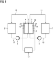
- FIG. 1 shows a rechargeable redox flow battery 1.
- the rechargeable redox flow battery 1 comprises a redox flow unit 20.
- the redox flow unit 20 comprises a membrane 3, the membrane 3 having a first chamber 4 and a second Separates chamber 5.
- a cathode 15 is arranged in the first chamber 4.
- An anode 16 is arranged in the second chamber 5.
- the cathode 15 and the anode 16 are connected to a power grid via an electrical power connection 12.
- the rechargeable redox flow battery 1 further comprises a first tank 6, which is connected to the first chamber 4 with the cathode 15 by means of a first pump 8 via a first line.
- the first chamber 4 is in turn connected to the first tank 6 via a third line 10.
- the rechargeable redox flow battery 1 comprises a second tank 7 which is connected via a second pump 9 to the second chamber 5 to the anode 16 via a second line 18.
- the second chamber 5 is in turn connected to the second tank 7 by a
- FIG. 2 shows a first embodiment of a redox flow unit 20 with a first chamber 4, in which a porous graphite electrode, in this case the cathode 15, is arranged.
- the redox flow unit 20 further comprises a second chamber 5, in which a planar anode 16 with elongate elevations 27 is arranged.
- the cathode 15 borders directly on a current collector 22.
- the anode 16 also borders on a current collector 21.
- the graphite electrode 15 touches both the current collector 22 and the membrane 3.
- the anode completely touches the collector 21 and the membrane partially by means of the elevations 27.
- Flow channels 26 are formed between the elevations 27.
- the flow channel has a first width 36 and a second width 37.
- the second width 37 increases in this exemplary embodiment.
- the first width 36 is typically in a range from 0.5 mm to 20 mm, preferably from 1 mm to 10 mm.
- the second width 37 of the flow channel 24 is typically in a range from 0.05 mm to 20 mm, particularly preferably from 0.1 mm to 10 mm.
- the first width 36 is constant. Alternatively, it is also possible for the first and second widths 36, 37 to decrease along the flow channel 26 or to be constant for widths.
- the cross sections can in particular be selected as a function of a desired target residence time of the anolyte at the anode.
- the flow channels 26 are delimited on three sides by the anode 16 and on one side by the membrane 3.
- the planar anode 16 comprises a first material 25, the first material in this exemplary embodiment comprising at least 10% lead.
- the anode 16 itself is not porous.
- the anode 16 can comprise at least 10% bismuth.
- the anode can further comprise carbon and carbon. Alloys, especially those made of lead or bismuth, can also be used.
- An electrolyte as catholyte 23 is fed into the first chamber 4.
- the catholyte 23 flows through the pore structure of the graphite electrode 15.
- An electrolyte as an anolyte is fed into the second chamber 5.
- the anolyte flows in a meandering fashion through the flow channels 26 of the anode 16.
- the residence time of the anolyte at the anode is reduced compared to porous electrodes, the reduction-oxidation pairs typically used in redox flow cells, in particular based on polyoxometalate, can also be of short length Residence times are effectively reduced or oxidized.
- the residence time can be changed using the shape of the flow channels 26 so that the dwell time can be adjusted depending on the reduction-oxidation pair used.
- the low overvoltage potential compared to hydrogen advantageously reduces hydrogen production at the anode compared to porous electrodes.
- Figure 3 shows a second embodiment of a redox flow unit 20 with a porous graphite electrode in the first chamber 4 and a planar anode 16 with elevations 27 in the second chamber 5.
- the anode only touches the current collector 21, but not the membrane 3.
- the anode 16 in this second exemplary embodiment comprises two materials which are arranged in layers one above the other.
- the base body of the anode 16 essentially comprises the second material 28 and is coated with a layer comprising the first material 25.
- the second material 28 comprises polymer fibers.
- the second material can also comprise carbon fibers.
- An electrolyte is supplied as a catholyte in the first chamber 4.
- the catholyte flows through the pore structure of the graphite electrode.
- An electrolyte as an anolyte is fed into the second chamber 5.
- the anolyte flows along the flow channel 26 and also penetrates into the depressions between the elevations 27.
- This arrangement is particularly suitable for reduction-oxidation pairs, which have a short residence time at the anode to ensure a sufficient degree of oxidation for storing the energy.
- Such a structure is particularly suitable if a polyoxometalate is used as the reduction-oxidation pair.
- Figure 4 shows a redox flow unit 20 according to a third embodiment.
- the first chamber 4 there is a planar one Cathode 30 with elevations 27 and flow channels 26 arranged.
- a planar anode 16 with elevations 27 is arranged in the second chamber 5.
- the elevations 27 differ in their shape.
- the cathode 30 has cuboid elevations, the anode 16 has pyramid elevations. In this example, the tips of the pyramid touch the membrane 3.
- Flow channels 26 thus form, through which the anolyte can flow.
- the catholyte also flows in a meandering manner over the cathode 30.
- the exemplary embodiments can be combined with one another.
- the anode in the first exemplary embodiment also comprises two layers. All of the above-mentioned designs of the anode can also be transferred to the cathode.
- a planar cathode 30 with elevations 27 in the first chamber 4 and a porous anode can be arranged in a redox flow unit 2.
- the elevations 27 on the electrode can have different shapes in all three exemplary embodiments. The different shapes are in the Figures 5 to 9 illustrated by the anode 16. However, they can also be transferred to the cathode 30.
- Figure 5 shows elevations 27 as they are arranged in the first and second exemplary embodiments for the anode 16 and in the third exemplary embodiment for the cathode 30.
- the elevations form a meandering river channel 26.
- FIG. 6 each shows flow channels 26, which are formed by cavities in cylindrical or cuboid elevations 27. These flow channels 26 have a very short residence time for the electrolyte at the electrode.
- the dwell time here is similar to a completely planar one, essentially smooth, surface of an electrode. Such an electrode is also conceivable, but not shown here.
- the anode 16 comprises in Figure 7 hemispherical elevations 31, in Figure 8 pyramidal elevations 34 and in Figure 9 cube-shaped surveys 35.
- the number of surveys can be different.
Landscapes
- Chemical & Material Sciences (AREA)
- Chemical Kinetics & Catalysis (AREA)
- Electrochemistry (AREA)
- General Chemical & Material Sciences (AREA)
- Engineering & Computer Science (AREA)
- Manufacturing & Machinery (AREA)
- Life Sciences & Earth Sciences (AREA)
- Sustainable Development (AREA)
- Sustainable Energy (AREA)
- Inert Electrodes (AREA)
- Fuel Cell (AREA)
Description
- Die Erfindung betrifft eine Redox-Flow-Batterie und ein Verfahren zum Betreiben einer Redox-Flow-Batterie.
- Die Nachfrage nach Strom schwankt im tageszeitlichen Verlauf stark. Auch die Stromerzeugung schwankt mit zunehmendem Anteil an Strom aus erneuerbaren Energien während des Tagesverlaufs. Um ein Überangebot an Strom in Zeiten mit viel Sonne und starkem Wind bei niedriger Nachfrage nach Strom ausgleichen zu können, benötigt man regelbare Kraftwerke oder Speicher, um diese Energie zu speichern.
- Batterien sind Speicher für elektrische Energie auf elektrochemischer Basis und geeignet, die überschüssige Energie zu speichern. Handelt es sich um einen wiederaufladbaren Speicher wird dieser auch Akkumulator genannt. Ein einzelnes wiederaufladbares Speicherelement wird auch Sekundärelement genannt.
- Bei Redox-Flow-Batterien ist, im Unterschied zu klassischen Sekundärelementen, das elektrodenaktive Material flüssig. Dieser flüssige Elektrolyt wird in einem Tank gelagert und in einen Kathodenraum mit einer Kathode und/oder in einen Anodenraum mit einer Anode gepumpt. Der flüssige Elektrolyt umfasst als elektrodenaktives Material daher zweckmäßigerweise ein Reduktions-Oxidations-Paar.
- An den Elektroden wird das elektrodenaktive Material reduziert oder oxidiert. Die Elektroden umfassen typischerweise Graphit oder Carbon. Die Struktur der Elektroden ist typischerweise porös in Art eines Vlies oder eines Fells, oder in anderen Worten in Form eines Gitters oder Strukturelements, ausgebildet, um eine möglichst große Oberfläche der Elektroden bereitzustellen. Nachteiligerweise findet an diesen Elektroden die Wasserstoffbildungsreaktion (englisch: hydrogen evolution reaction, HER) statt. Dies führt nachteilig dazu, dass zwischen Anolyt und Katholyt ungleiche Ladungsverhältnisse vorliegen. Der Faradaysche Wirkungsgrad wird dadurch nachteilig deutlich verringert.
- Es ist daher Aufgabe der vorliegenden Erfindung eine Redox-Flow-Batterie und ein Verfahren zum Betreiben einer Redox-Flow-Batterie anzugeben, welche einen verbesserten Faradayschen Wirkungsgrad aufweist.
- Die Aufgabe wird mittels einer elektrisch wiederaufladbaren Redox-Flow-Batterie nach Anspruch 1 und einem Verfahren zum Betreiben einer Redox-Flow-Batterie nach Anspruch 10 gelöst.
- Erfindungsgemäß umfasst eine elektrisch wiederaufladbare Redox-Flow-Batterie eine erste Kammer und eine zweite Kammer. Die erste Kammer ist von der zweiten Kammer mittels einer Membran getrennt. Die erste Kammer umfasst eine Kathode und die zweite Kammer umfasst eine Anode. Eine erste planare Oberfläche der Kathode und/oder eine zweite planare Oberfläche der Anode weist Erhebungen zur Vergrößerung der Oberfläche auf. Diese Erhebungen sind geeignet, Flusskanäle für einen Elektrolyten der Redox-Flow Batterie zu bilden. Die Kathode und/oder die Anode umfassen wenigstens ein erstes Material, wobei das Material Blei, oder Bismut, mit einem Gewichtsanteil von wenigstens 20% umfasst.
- Das erfindungsgemäße Verfahren zum Betreiben einer Redox-Flow-Batterie umfasst mehrere Schritte. Zunächst erfolgt das Bereitstellen einer Redox-Flow-Batterie mit einer ersten Kammer und einer zweiten Kammer. Die erste Kammer ist von der zweiten Kammer mittels einer Membran getrennt. Die erste Kammer umfasst eine Kathode und die zweite Kammer umfasst eine Anode. Eine erste Oberfläche der Kathode und/oder eine zweite Oberfläche der Anode weist Erhebungen zur Vergrößerung der Oberfläche auf. Diese Erhebungen sind geeignet, Flusskanäle für einen ersten und/oder zweiten Elektrolyten der Redox-Flow Batterie zu bilden. Die Kathode und/oder die Anode umfassen wenigstens ein erstes Material, wobei das erste Material Blei oder Bismut umfasst. Ein erster Elektrolyt wird in die erste Kammer geführt und ein zweiter Elektrolyt wird in die zweite Kammer geführt. In den beiden Kammern erfolgt dann das Aufladen oder Entladen der Redox-Flow-Batterie.
- Die Kathode und/oder die Anode sind im Wesentlichen planar. Auf der Kathode und/oder der Anode sind Erhebungen angeordnet. Unter Erhebungen werden hier strukturierte Erhebungen insbesondere in Form von zylinderförmigen, würfelförmigen, pyramidenförmigen oder halbkugelförmigen Erhebungen verstanden. Zwischen den Erhebungen bilden sich Flusskanäle aus, durch die der erste und/oder zweite Elektrolyt fließen kann.
- Die erfindungsgemäß verwendeten Materialien Blei oder Bismut weisen ein höheres Überspannungspotential gegenüber der Wasserstoffentwicklung auf als übliche Kohlenstoff- oder Graphit-Elektroden. Insbesondere ist das Überspannungspotential gegenüber Wasserstoff bei 25 °C kleiner als - 0,6 V. Dadurch kann das angelegte elektrische Potential an der Anode negativer sein als mit Kohlenstoff- oder Graphitelektroden, wodurch vorteilhaft mehr Elektronen pro Molekül des Reduktions-Oxidations-Paares von der Anode zur Kathode transferiert werden können. Vorteilhafterweise erhöht sich dadurch die Faraday-Effizienz und somit die gesamte Effizienz der Redox-Flow-Batterie. Der elektrische Strom wird also effizient auf ein Reduktions-Oxidations-Paar im Elektrolyten übertragen, dadurch dass dieser reduziert bzw. oxidiert wird. Die zu dieser Reaktion konkurrierende Wasserstoffbildungsreaktion wird deutlich reduziert. Weiterhin wird ein auseinanderlaufen des ersten Elektrolyten, also des Katholyts, und des zweiten Elektrolyten, also des Anolyts, hinsichtlich des pH-Wertes vermieden.
- Insbesondere wenn als Reduktions-Oxidations-Paar Polyoxometallate verwendet werden, schädigt der veränderte pH-Wert aufgrund der Verwendung eines Protons bei der Wasserstoffentwicklung die Polyoxometallate, insbesondere im Anolyt. Vorteilhaft kann die Redox-Flow-Batterie längere Zeit betrieben werden, wenn die Wasserstoffbildungsreaktion vermindert wird, ohne dass der erste und/oder zweite Elektrolyt ausgetauscht werden muss.
- Weiterhin ist es vorteilhaft möglich, durch das Verwenden der planaren bzw. flachen Elektroden, den Druckverlust entlang der Elektrode in Flussrichtung der Elektrode zu vermindern. Dies verbessert die Energieeffizienz der Redox-Flow-Batterie vorteilhaft.
- In einer vorteilhaften Ausgestaltung und Weiterbildung der Erfindung umfasst die Kathode und/oder Anode als das erste Material Blei oder Bismut. Diese Materialien können mit organischen Reduktions-Oxidations-Paaren auf Chinon-Basis, insbesondere AQDSH2/AQDS (AQDS bedeutet 9, 10 Anthraquinon-2,7-diSulfonsäure) und Br2/ 2 HBr, eingesetzt werden. Es ist ebenfalls vorteilhaft möglich, Blei oder Bismut als Elektrodenmaterial mit organischen Reduktions-Oxidations-Paaren auf Polymerbasis einzusetzen, insbesondere Polymere mit der Basis TEMPO/TEMPO+ (TEMPO bedeutet 2,2,6,6-Tetramethylpiperidinyloxyl) und basierend auf Viologenen, in anderen Worten, N'-dialkyl-4,4'-Bipyridine (Viol2-/Viol+). Besonders vorteilhaft sind Blei und Bismut leicht zugänglich und im Vergleich zu anderen Materialien nicht teuer.
- In einer weiteren vorteilhaften Ausgestaltung und Weiterbildung der Erfindung weisen die Erhebungen eine erste lange Seite und eine zweite kurze Seite auf. Die Erhebungen sind also im Wesentlichen rechteckig ausgeführt. Dadurch bilden sich zwischen den Erhebungen längliche Flusskanäle, durch die der erste und/oder zweite Elektrolyt fließen kann. Die Erhebungen sind insbesondere parallel oder mäanderförmig angeordnet. Im Falle der parallelen Anordnung entstehen parallele Flusskanäle, wodurch der erste und/oder zweite Elektrolyt durch mehrere einzelne Flusskanäle durch die Redox-Flow Batterie geführt wird. Im Falle der mandelförmig angeordneten Erhebungen und somit auch der mäanderförmigen Flusskanäle ergibt sich ein langer Flusskanal durch die Redox-Flow Batterie.
- In der erfindungsgemässen Ausgestaltung und Weiterbildung der Erfindung umfasst das erste Material Blei oder Bismut mit einem Gewichtsanteil von wenigstens 20 %, insbesondere von wenigstens 40 %. Blei oder Bismut sind also nicht nur zu geringen Teilen, insbesondere als Verunreinigung, in den Elektroden enthalten, sondern stellen ein wesentliches Material der Elektroden dar. Vorteilhaft garantiert dies, dass das Überspannungspotential gegenüber Wasserstoff derart niedrig ist, dass kein oder nahezu kein Wasserstoff in der Redox-Flow-Batterie produziert wird.
- In einer weiteren vorteilhaften Ausgestaltung und Weiterbildung der Erfindung berühren die Kathode und/oder die Anode die Membran wenigstens teilweise direkt. Dadurch grenzt die Membran, die insbesondere an die Erhebungen angrenzt einen Flusskanal ab. Vorteilhaft wird so die Flussrichtung des ersten und/oder zweiten Elektrolyten in der Redox-Flow-Batterie definiert vorgegeben. Dadurch lässt sich die Kontaktfläche, welche der erste und/oder zweite Elektrolyt mit den Elektroden aufweist, vorteilhaft festlegen.
- In einer weiteren vorteilhaften Ausgestaltung und Weiterbildung der Erfindung umfasst die Kathode und/oder die Anode ein zweites Material, wobei das zweite Material Polymerfasern oder Kohlenstofffasern umfasst. Vorteilhaft stabilisieren die Fasern die jeweilige Form der Anode und/oder Kathode. Weiterhin wird, in Abhängigkeit des eingesetzten Elektrodenmaterials, teures Material durch günstigeres Fasermaterial ersetzt. Dies senkt die Herstellungskosten der Elektrode vorteilhaft.
- In einer weiteren vorteilhaften Ausgestaltung und Weiterbildung der Erfindung beträgt ein Gewichtsanteil des zweiten Materials wenigstens 10 %, besonders vorteilhaft wenigstens 15 %.
- In einer weiteren vorteilhaften Ausgestaltung und Weiterbildung der Erfindung ist das erste Material als eine Schicht auf dem zweiten Material angeordnet. Vorteilhaft werden so die Herstellungskosten möglichst niedrig gehalten, da die Herstellung des zweiten Materials günstiger ist und eine ausreichend dicke Schicht des ersten Materials das geforderte Überspannungspotential gegenüber Wasserstoff aufweist. Bevorzugt liegt die Dicke der Schicht in einem Bereich von 3 µm und 50 µm, besonders bevorzugt in einem Bereich von 5 µm bis 20 µm.
- In einer weiteren vorteilhaften Ausgestaltung und Weiterbildung der Erfindung ist die Anode und/oder Kathode als eine Ballelektrode oder eine Stabelektrode ausgestaltet. Diese Formen der Elektroden sind vorteilhaft besonders einfach herstellbar.
- In einer vorteilhaften Ausgestaltung und Weiterbildung der Erfindung wird als Reduktions-Oxidations-Paar im ersten und/oder zweiten Elektrolyten Polyoxometallat verwendet.
- Weitere Merkmale, Eigenschaften und Vorteile der vorliegenden Erfindung ergeben sich aus der nachfolgenden Beschreibung unter Bezugnahme der beiliegenden Figuren.
- Figur 1
- zeigt eine wiederaufladbare Redox-Flow-Batterie mit einer Redox-Flow-Einheit mit planarer Elektrode;
- Figur 2
- zeigt eine Redox-Flow-Einheit mit einer Anode mit Flusskanälen umfassend Blei;
- Figur 3
- zeigt eine Redox-Flow-Einheit mit einer Anode mit Flusskanälen umfassend zwei Schichten;
- Figur 4
- zeigt eine Redox-Flow-Einheit mit einer Kathode mit einer ersten Form von Flusskanälen und einer Anode mit einer zweiten Form von Flusskanälen;
- Figur 5
- zeigt eine planare Anode mit mäanderförmig angeordneten Erhebungen;
- Figur 6
- zeigt eine planare Anode mit länglichen Erhebungen;
- Figur 7
- zeigt eine planare Anode mit halbkugelförmigen Erhebungen;
- Figur 8
- zeigt eine planare Anode mit pyramidenförmigen Erhebungen;
- Figur 9
- zeigt eine planare Anode mit würfelförmigen Erhebungen.
-
Figur 1 zeigt eine wiederaufladbare Redox-Flow-Batterie 1. Die wiederaufladbare Redox-Flow-Batterie 1 umfasst eine Redox-Flow-Einheit 20. Die Redox-Flow-Einheit 20 umfasst eine Membran 3, wobei die Membran 3 eine erste Kammer 4 und eine zweite Kammer 5 voneinander trennt. In der ersten Kammer 4 ist eine Kathode 15 angeordnet. In der zweiten Kammer 5 ist eine Anode 16 angeordnet. Die Kathode 15 und die Anode 16 sind über eine Elektroenergieanbindung 12 mit einem Stromnetz verbunden. Die wiederaufladbare Redox-Flow-Batterie 1 umfasst weiterhin einen ersten Tank 6, welcher mittels einer ersten Pumpe 8 über eine erste Leitung mit der ersten Kammer 4 mit der Kathode 15 verbunden ist. Die erste Kammer 4 ist wiederum über eine dritte Leitung 10 mit dem ersten Tank 6 verbunden. Die wiederaufladbare Redox-Flow-Batterie 1 umfasst einen zweiten Tank 7 der über eine zweite Pumpe 9 mit der zweiten Kammer 5 mit der Anode 16 über eine zweite Leitung 18 verbunden ist. Die zweite Kammer 5 ist wiederum mit einer vierten Leitung 11 mit dem zweiten Tank 7 verbunden. -
Figur 2 zeigt ein erstes Ausführungsbeispiel einer Redox-Flow-Einheit 20 mit einer ersten Kammer 4, in welcher eine poröse Graphitelektrode, in diesem Fall die Kathode 15, angeordnet ist. Die Redox-Flow-Einheit 20 umfasst weiterhin eine zweite Kammer 5, in welcher eine planare Anode 16 mit länglichen Erhebungen 27 angeordnet ist. Die Kathode 15 grenzt direkt an einen Stromkollektor 22. Die Anode 16 grenzt ebenfalls an einen Stromkollektor 21. Die Graphitelektrode 15 berührt sowohl den Stromkollektor 22 als auch die Membran 3. - Die Anode berührt den Kollektor 21 vollständig und die Membran mittels der Erhebungen 27 teilweise. Zwischen den Erhebungen 27 bilden sich Flusskanäle 26. Der Flusskanal weist eine erste Breite 36 und eine zweite Breite 37 auf. Die zweite Breite 37 nimmt in diesem Ausführungsbeispiel zu. Die erste Breite 36 liegt typischerweise in einem Bereich von 0,5 mm bis 20 mm, bevorzugt von 1 mm bis 10 mm. Die zweite Breite 37 des Flusskanals 24 liegt typischerweise in einem Bereich von 0,05 mm bis 20 mm, besonders bevorzugt von 0,1 mm bis 10 mm. Die erste Breite 36 ist konstant. Es ist alternativ auch möglich, dass die erste und zweite Breite 36, 37 entlang des Flusskanals 26 abnehmen oder bei breiten konstant sind. Die Querschnitte können insbesondere in Abhängigkeit einer gewünschten Ziel-Verweilzeit des Anolyts an der Anode gewählt werden. Die Flusskanäle 26 werden an drei Seiten von der Anode 16 und an einer Seite von der Membran 3 begrenzt. Die planare Anode 16 umfasst ein erstes Material 25, wobei das erste Material in diesem Ausführungsbeispiel wenigstens 10 % Blei umfasst. Die Anode 16 selbst ist nicht porös. Alternativ kann die Anode 16 wenigstens 10 % Bismut umfassen. Die Anode kann weiterhin Kohlenstoff und Carbon umfassen. Auch Legierungen, insbesondere aus Blei oder Bismut können eingesetzt werden.
- In die erste Kammer 4 wird ein Elektrolyt als Katholyt 23 zugeführt. Der Katholyt 23 strömt durch die Porenstruktur der Graphitelektrode 15. In die zweite Kammer 5 wird ein Elektrolyt als Anolyt zugeführt. Der Anolyt fließt mäanderförmig durch die Flusskanäle 26 der Anode 16. Die Verweilzeit des Anolyts an der Anode ist zwar gegenüber porösen Elektroden verkürzt, die typischerweise in Redox-Flow Zellen eingesetzten Reduktions-Oxidations-Paare, insbesondere basierend auf Polyoxometallat, können aber auch mit kurzen Verweilzeiten effektiv reduziert bzw. oxidiert werden. Die Verweilzeit kann mithilfe der Form der Flusskanäle 26 verändert werden, sodass die Verweilzeit in Abhängigkeit des eingesetzten Reduktions-Oxidations-Paares angepasst werden kann. Durch das niedrige Überspannungspotential gegenüber Wasserstoff wird die Wasserstoffproduktion an der Anode gegenüber porösen Elektroden vorteilhaft verringert.
-
Figur 3 zeigt ein zweites Ausführungsbeispiel einer Redox-Flow-Einheit 20 mit einer porösen Graphitelektrode in der ersten Kammer 4 und einer planaren Anode 16 mit Erhebungen 27 in der zweiten Kammer 5. Im Unterschied zum ersten Ausführungsbeispiel ausFigur 2 , berührt die Anode lediglich den Stromkollektor 21, nicht aber die Membran 3. Weiterhin umfasst die Anode 16 in diesem zweiten Ausführungsbeispiel zwei Materialien, welche schichtartig übereinander angeordnet sind. Der Grundkörper der Anode 16 umfasst im Wesentlichen das zweite Material 28 und ist mit einer Schicht umfassend das erste Material 25 beschichtet. In diesem Ausführungsbeispiel umfasst das zweite Material 28 Polymerfasern. Alternativ kann das zweite Material auch Kohlenstofffasern umfassen. - In die erste Kammer 4 wird ein Elektrolyt als Katholyt zugeführt. Der Katholyt strömt durch die Porenstruktur der Graphitelektrode. In die zweite Kammer 5 wird ein Elektrolyt als Anolyt zugeführt. Der Anolyt fließt entlang des Flusskanals 26 und dringt dabei auch in die Vertiefungen zwischen den Erhebungen 27 ein. Diese Anordnung eignet sich insbesondere für Reduktions-Oxidations-Paare, welchen eine geringe Verweilzeit an der Anode ausreicht, um einen ausreichenden Oxidationsgrad zum Speichern der Energie zu gewährleisten. Insbesondere eignet sich ein solcher Aufbau, wenn als Reduktions-Oxidations-Paar ein Polyoxometallat eingesetzt wird.
-
Figur 4 zeigt eine Redox-Flow-Einheit 20 gemäß einem dritten Ausführungsbeispiel. In der ersten Kammer 4 ist eine planare Kathode 30 mit Erhebungen 27 und Flusskanälen 26 angeordnet. In der zweiten Kammer 5 ist eine planare Anode 16 mit Erhebungen 27 angeordnet. Die Erhebungen 27 unterscheiden sich in ihrer Form. Die Kathode 30 weist quaderförmige Erhebungen auf, die Anode 16 weist pyramidenförmige Erhebungen auf. Die Spitzen der Pyramide berühren in diesem Beispiel die Membran 3. Es bilden sich also Flusskanäle 26 aus, durch die der Anolyt fließen kann. Auch der Katholyt fließt in diesem Beispiel mäanderförmig über die Kathode 30. - Die Ausführungsbeispiele können miteinander kombiniert werden. So ist es insbesondere möglich, dass auch die Anode im ersten Ausführungsbeispiel zwei Schichten umfasst. Alle genannten Ausführungen der Anode können ebenso auf die Kathode übertragen werden. Insbesondere kann eine planare Kathode 30 mit Erhebungen 27 in der ersten Kammer 4 und eine poröse Anode in einer Redox-Flow-Einheit 2 angeordnet sein. Weiterhin können die Erhebungen 27 auf der Elektrode in allen drei Ausführungsbeispielen unterschiedliche Formen aufweisen. Die unterschiedlichen Formen werden in den
Figuren 5 bis 9 anhand der Anode 16 verdeutlicht. Sie können aber ebenso auf die Kathode 30 übertragen werden. -
Figur 5 zeigt Erhebungen 27, wie sie im ersten und zweiten Ausführungsbeispiel bei der Anode 16 und im dritten Ausführungsbeispiel bei der Kathode 30 angeordnet sind. Die Erhebungen bilden einen mäanderförmigen Flusskanal 26. -
Figur 6 zeigt jeweils Flusskanäle 26, welche durch Hohlräume in zylinder- oder quaderförmigen Erhebungen 27 gebildet werden. Diese Flusskanäle 26 weisen eine sehr kurze Verweilzeit für den Elektrolyten an der Elektrode auf. Die Verweilzeit hier ist ähnlich wie eine komplett planare, im Wesentlichen glatte, Oberfläche einer Elektrode. Auch solch eine Elektrode ist denkbar, hier aber nicht gezeichnet. - Die Anode 16 umfasst in
Figur 7 halbkugelförmige Erhebungen 31, inFigur 8 pyramidenförmige Erhebungen 34 und inFigur 9 würfelförmige Erhebungen 35. Die Anzahl der Erhebungen kann unterschiedlich sein. Je mehr Erhebungen auf der Anode 16 angeordnet sind, je höher wird die Verweilzeit des Anolyts an der Anode 16.
Claims (11)
- Elektrisch wiederaufladbare Redox-Flow-Batterie (1) mit einer ersten Kammer (4) und einer zweiten Kammer (5), wobei die erste Kammer (4) von der zweiten Kammer (5) mittels einer Membran (3) getrennt ist, wobei die erste Kammer (4) eine Kathode (30) umfasst und die zweite Kammer (5) eine Anode (16) umfasst, und wobei eine erste planare Oberfläche der Kathode (30) und/oder eine zweite planare Oberfläche der Anode (16) Erhebungen (27) zur Vergrößerung der Oberfläche aufweist und diese Erhebungen (27) geeignet sind, Flusskanäle (26) für einen ersten und/oder zweiten Elektrolyten der Redox-Flow Batterie (1) zu bilden, wobei die Kathode (30) und/oder die Anode (16) wenigstens ein erstes Material (25) umfassend Blei oder Bismut umfassen, wobei das erste Material (25) Blei oder Bismut mit einem Gewichtanteil von wenigstens 20% umfasst.
- Redox-Flow-Batterie (1) nach Anspruch 1, wobei die Erhebungen (27) eine erste lange Seite und eine zweite kurze Seite (36) aufweisen.
- Redox-Flow-Batterie (1) nach einem der vorhergehenden Ansprüche, wobei die Erhebungen (27) parallel oder mäanderförmig angeordnet sind.
- Redox-Flow-Batterie (1) nach einem der vorhergehenden Ansprüche, wobei das erste Material (25) Blei oder Bismut mit einem Gewichtsanteil von wenigstens 40% umfasst.
- Redox-Flow-Batterie (1) nach einem der vorhergehenden Ansprüche, wobei die Kathode (30) und/oder die Anode (16) die Membran (3) wenigstens teilweise direkt berühren.
- Redox-Flow-Batterie (1) nach einem der vorhergehenden Ansprüche, wobei die Kathode (30) und/oder Anode (16) ein zweites Material (28) umfassen und wobei das zweite Material (28) Polymerfasern oder Kohlenstofffasern umfasst.
- Redox-Flow-Batterie (1) nach Anspruch 6, wobei ein Gewichtsanteil des zweiten Materials wenigstens 10% beträgt.
- Redox-Flow-Batterie (1) nach Anspruch 7, wobei das erste Material (25) als eine Schicht auf dem zweiten Material (28) angeordnet ist.
- Redox-Flow-Batterie (1) nach einem der vorhergehenden Ansprüche, wobei die Anode (16) und/oder Kathode (30) eine Ballelektrode oder eine Stabelektrode ist.
- Verfahren zum Betreiben einer Redox-Flow-Batterie (1) mit folgenden Schritten:- Bereitstellen einer Redox-Flow-Batterie (1) mit einer ersten Kammer (4) und einer zweiten Kammer (5), wobei die erste Kammer (4) von der zweiten Kammer (5) mittels einer Membran (3) getrennt ist, wobei die ersten Kammer (4) eine Kathode (30) umfasst und die zweite Kammer (5) eine Anode (16) umfasst, wobei eine erste Oberfläche der Kathode (30) und/oder eine zweite Oberfläche der Anode (16) Erhebungen (27) zur Vergrößerung der Oberfläche aufweist und diese Erhebungen (27) geeignet sind, Flusskanäle (26) für einen ersten und/oder zweiten Elektrolyten der Redox-Flow Batterie (1) zu bilden, und die Kathode (30) und/oder die Anode (16) wenigstens ein erstes Material (25) umfassend Blei oder Bismut, umfassen, wobei das erste Material (25) Blei oder Bismut mit einem Gewichtanteil von wenigstens 20% umfasst,- Führen eines ersten Elektrolyten in die erste Kammer (4) und Führen eines zweiten Elektrolyten in die zweite Kammer (5),- Aufladen oder Entladen der Redox-Flow-Batterie (1).
- Verfahren nach Anspruch 10, wobei als ein Reduktions-Oxidationspaar im Elektrolyten Polyoxometallat verwendet wird.
Priority Applications (8)
| Application Number | Priority Date | Filing Date | Title |
|---|---|---|---|
| DK17275122.4T DK3439093T3 (da) | 2017-08-04 | 2017-08-04 | Redox-flow-batteri og fremgangsmåde til drift af et redox-flow-batteri |
| EP17275122.4A EP3439093B1 (de) | 2017-08-04 | 2017-08-04 | Redox-flow-batterie und verfahren zum betreiben einer redox-flow-batterie |
| ES17275122T ES2781301T3 (es) | 2017-08-04 | 2017-08-04 | Batería de flujo redox y procedimiento para el funcionamiento de una batería de flujo redox |
| JP2019565811A JP2020523731A (ja) | 2017-08-04 | 2018-07-18 | レドックスフロー電池およびレドックスフロー電池を作動するための方法 |
| EP18748872.1A EP3625845A1 (de) | 2017-08-04 | 2018-07-18 | Redox-flow-batterie und verfahren zum betreiben einer redox-flow-batterie |
| US16/636,221 US11424471B2 (en) | 2017-08-04 | 2018-07-18 | Redox flow battery |
| CN201880050194.2A CN110998946A (zh) | 2017-08-04 | 2018-07-18 | 氧化还原液流电池和运行氧化还原液流电池的方法 |
| PCT/EP2018/069538 WO2019025190A1 (de) | 2017-08-04 | 2018-07-18 | Redox-flow-batterie und verfahren zum betreiben einer redox-flow-batterie |
Applications Claiming Priority (1)
| Application Number | Priority Date | Filing Date | Title |
|---|---|---|---|
| EP17275122.4A EP3439093B1 (de) | 2017-08-04 | 2017-08-04 | Redox-flow-batterie und verfahren zum betreiben einer redox-flow-batterie |
Publications (2)
| Publication Number | Publication Date |
|---|---|
| EP3439093A1 EP3439093A1 (de) | 2019-02-06 |
| EP3439093B1 true EP3439093B1 (de) | 2020-01-15 |
Family
ID=59558345
Family Applications (2)
| Application Number | Title | Priority Date | Filing Date |
|---|---|---|---|
| EP17275122.4A Active EP3439093B1 (de) | 2017-08-04 | 2017-08-04 | Redox-flow-batterie und verfahren zum betreiben einer redox-flow-batterie |
| EP18748872.1A Withdrawn EP3625845A1 (de) | 2017-08-04 | 2018-07-18 | Redox-flow-batterie und verfahren zum betreiben einer redox-flow-batterie |
Family Applications After (1)
| Application Number | Title | Priority Date | Filing Date |
|---|---|---|---|
| EP18748872.1A Withdrawn EP3625845A1 (de) | 2017-08-04 | 2018-07-18 | Redox-flow-batterie und verfahren zum betreiben einer redox-flow-batterie |
Country Status (7)
| Country | Link |
|---|---|
| US (1) | US11424471B2 (de) |
| EP (2) | EP3439093B1 (de) |
| JP (1) | JP2020523731A (de) |
| CN (1) | CN110998946A (de) |
| DK (1) | DK3439093T3 (de) |
| ES (1) | ES2781301T3 (de) |
| WO (1) | WO2019025190A1 (de) |
Families Citing this family (6)
| Publication number | Priority date | Publication date | Assignee | Title |
|---|---|---|---|---|
| ES2781301T3 (es) | 2017-08-04 | 2020-09-01 | Siemens Ag | Batería de flujo redox y procedimiento para el funcionamiento de una batería de flujo redox |
| WO2021222332A1 (en) | 2020-04-29 | 2021-11-04 | Bristol-Myers Squibb Company | Miniaturized dystrophins having spectrin fusion domains and uses thereof |
| CN115668562A (zh) * | 2020-05-15 | 2023-01-31 | Ess技术有限公司 | 用于氧化还原液流电池的电极组件 |
| EP4181239A1 (de) | 2021-11-15 | 2023-05-17 | Litricity GmbH | Elektrochemische zelle |
| US11881605B2 (en) * | 2022-02-25 | 2024-01-23 | The Chinese University Of Hong Kong | Low-temperature aqueous redox flow battery |
| WO2023200652A1 (en) * | 2022-04-15 | 2023-10-19 | Washington University | Electrode-decoupled redox flow battery |
Family Cites Families (15)
| Publication number | Priority date | Publication date | Assignee | Title |
|---|---|---|---|---|
| JPH02195650A (ja) * | 1989-01-23 | 1990-08-02 | Sumitomo Electric Ind Ltd | レドックスフロー電池用電極 |
| JP3844103B2 (ja) * | 1998-06-10 | 2006-11-08 | 東洋紡績株式会社 | 液流通型電解槽用溝付き電極材及びその製造方法 |
| JP4823446B2 (ja) * | 2001-08-22 | 2011-11-24 | 株式会社フジコー | 凹凸面フェルト材 |
| GB0718577D0 (en) * | 2007-09-24 | 2007-10-31 | Acal Energy Ltd | Fuel cells |
| CN106159189B (zh) * | 2010-03-30 | 2019-11-01 | 应用材料公司 | 高性能ZnFe液流电池组 |
| US8486567B2 (en) * | 2010-05-10 | 2013-07-16 | Gas Technology Institute | Batteries, fuel cells, and other electrochemical devices |
| JP6034788B2 (ja) * | 2010-09-08 | 2016-11-30 | プリマス パワー コーポレイション | フロー電池用金属電極組立品 |
| JP2013004351A (ja) * | 2011-06-17 | 2013-01-07 | Jx Metals Trading Co Ltd | レドックスフロー電池用電極材及びそれを備えたレドックスフロー電池 |
| JP6018450B2 (ja) * | 2012-07-31 | 2016-11-02 | 東邦テナックス株式会社 | 炭素繊維フェルト、その製造方法、及び電極 |
| US20140050947A1 (en) * | 2012-08-07 | 2014-02-20 | Recapping, Inc. | Hybrid Electrochemical Energy Storage Devices |
| US9685651B2 (en) * | 2012-09-05 | 2017-06-20 | Ess Tech, Inc. | Internally manifolded flow cell for an all-iron hybrid flow battery |
| CN104241661B (zh) * | 2014-09-23 | 2017-04-19 | 中国科学院金属研究所 | 一种全钒液流电池用复合电极的制备方法 |
| DE102015212234A1 (de) * | 2015-06-30 | 2017-01-26 | Sgl Carbon Se | Verfahren zur Herstellung von Kohlenstofffilzelektroden für Redox Flow Batterien |
| JP2017091617A (ja) * | 2015-11-02 | 2017-05-25 | 旭化成株式会社 | カーボンフェルト、二次電池、及び、カーボンフェルトの製造方法 |
| ES2781301T3 (es) | 2017-08-04 | 2020-09-01 | Siemens Ag | Batería de flujo redox y procedimiento para el funcionamiento de una batería de flujo redox |
-
2017
- 2017-08-04 ES ES17275122T patent/ES2781301T3/es active Active
- 2017-08-04 EP EP17275122.4A patent/EP3439093B1/de active Active
- 2017-08-04 DK DK17275122.4T patent/DK3439093T3/da active
-
2018
- 2018-07-18 CN CN201880050194.2A patent/CN110998946A/zh active Pending
- 2018-07-18 EP EP18748872.1A patent/EP3625845A1/de not_active Withdrawn
- 2018-07-18 US US16/636,221 patent/US11424471B2/en active Active
- 2018-07-18 WO PCT/EP2018/069538 patent/WO2019025190A1/de unknown
- 2018-07-18 JP JP2019565811A patent/JP2020523731A/ja active Pending
Non-Patent Citations (1)
| Title |
|---|
| None * |
Also Published As
| Publication number | Publication date |
|---|---|
| ES2781301T3 (es) | 2020-09-01 |
| CN110998946A (zh) | 2020-04-10 |
| US11424471B2 (en) | 2022-08-23 |
| EP3625845A1 (de) | 2020-03-25 |
| EP3439093A1 (de) | 2019-02-06 |
| JP2020523731A (ja) | 2020-08-06 |
| WO2019025190A1 (de) | 2019-02-07 |
| DK3439093T3 (da) | 2020-04-14 |
| US20200168938A1 (en) | 2020-05-28 |
Similar Documents
| Publication | Publication Date | Title |
|---|---|---|
| EP3439093B1 (de) | Redox-flow-batterie und verfahren zum betreiben einer redox-flow-batterie | |
| EP2893586B1 (de) | Elektrochemische zelle vom durchflusstyp | |
| EP3734724A1 (de) | Wiederaufladbare batteriezelle | |
| DE102013224302A1 (de) | Elektrochemische Zelle sowie Verfahren zum Herstellen einer elektrochemischen Zelle | |
| EP3456866A1 (de) | Verfahren zur herstellung eines interkonnektors, interkonnektor und dessen verwendung | |
| DE102016220685A1 (de) | Elektrode mit elektrisch leitendem Netzwerk auf Aktivmaterialstrukturen | |
| EP3625844A1 (de) | Redox-flow-batterie und verfahren zum betreiben einer redox-flow-batterie | |
| WO2018219783A1 (de) | Energiespeicher | |
| WO2019166324A1 (de) | Redox-flussbatterie mit wenigstens einer zelle und einem elektrodenelement sowie verfahren zur herstellung einer leiterstruktur eines elektrodenelements einer redox-flussbatterie | |
| DE102018112638A1 (de) | Phosphonium-basierte ionische Flüssigkeiten für Lithium-Metall-basierte Batterien | |
| DE102014104601A1 (de) | Elektrochemische Zelle, insbesondere für eine Redox-Flow-Batterie, sowie Verfahren zur Herstellung | |
| EP2888779B1 (de) | Elektrode für galvanische zelle | |
| DE102009048237A1 (de) | Elektrochemische Zelle und Verfahren zur Herstellung einer solchen Zelle | |
| EP3534435A1 (de) | Redox-flussbatterie mit wenigstens einer zelle sowie verfahren zum betreiben einer redox-flussbatterie | |
| DE102011084019A1 (de) | Batterie mit faser- oder fadenförmiger Elektrode | |
| EP4150137B1 (de) | Zellenstapel, verfahren zur herstellung eines zellenstapels sowie brennstoffzelle oder elektrolysezelle umfassend einen zellenstapel | |
| DE102022202213A1 (de) | Verfahren zum Herstellen einer Elektrode, Elektrode, Lithiumionenzelle | |
| DE3005725A1 (de) | Batterieelektrode | |
| EP1675205B1 (de) | Alkalischer Akkumulator | |
| DE102022205102A1 (de) | Verteilerstruktur für elektrochemische Zellen, Elektrolyseur und Power-to-X-Anlage | |
| DE102021001212A1 (de) | Kollektorfolie für eine Anode und/oder eine Kathode einer Lithium-Ionen-Batterie, sowie Lithium-Ionen-Batterie | |
| DE102018222728A1 (de) | Elektrode für chemische Reaktoren, insbesondere für Redox-Flow-Batterien und Redox-Flow-Batterie mit einer solchen Elektrode | |
| DE102005061908A1 (de) | Brennstoffzelleneinheit | |
| EP3005460A1 (de) | Verfahren zur verbindung eines elektrisch leitfähigen kontaktelements mit wenigstens einer einer brennstoffzelle zugeordneten, elektrisch leitfähigen brennstoffzellenkomponente | |
| DE2061598A1 (de) | Galvanische Speicherzelle |
Legal Events
| Date | Code | Title | Description |
|---|---|---|---|
| PUAI | Public reference made under article 153(3) epc to a published international application that has entered the european phase |
Free format text: ORIGINAL CODE: 0009012 |
|
| STAA | Information on the status of an ep patent application or granted ep patent |
Free format text: STATUS: THE APPLICATION HAS BEEN PUBLISHED |
|
| AK | Designated contracting states |
Kind code of ref document: A1 Designated state(s): AL AT BE BG CH CY CZ DE DK EE ES FI FR GB GR HR HU IE IS IT LI LT LU LV MC MK MT NL NO PL PT RO RS SE SI SK SM TR |
|
| AX | Request for extension of the european patent |
Extension state: BA ME |
|
| STAA | Information on the status of an ep patent application or granted ep patent |
Free format text: STATUS: REQUEST FOR EXAMINATION WAS MADE |
|
| 17P | Request for examination filed |
Effective date: 20190719 |
|
| RBV | Designated contracting states (corrected) |
Designated state(s): AL AT BE BG CH CY CZ DE DK EE ES FI FR GB GR HR HU IE IS IT LI LT LU LV MC MK MT NL NO PL PT RO RS SE SI SK SM TR |
|
| GRAP | Despatch of communication of intention to grant a patent |
Free format text: ORIGINAL CODE: EPIDOSNIGR1 |
|
| STAA | Information on the status of an ep patent application or granted ep patent |
Free format text: STATUS: GRANT OF PATENT IS INTENDED |
|
| INTG | Intention to grant announced |
Effective date: 20190911 |
|
| GRAS | Grant fee paid |
Free format text: ORIGINAL CODE: EPIDOSNIGR3 |
|
| GRAA | (expected) grant |
Free format text: ORIGINAL CODE: 0009210 |
|
| STAA | Information on the status of an ep patent application or granted ep patent |
Free format text: STATUS: THE PATENT HAS BEEN GRANTED |
|
| AK | Designated contracting states |
Kind code of ref document: B1 Designated state(s): AL AT BE BG CH CY CZ DE DK EE ES FI FR GB GR HR HU IE IS IT LI LT LU LV MC MK MT NL NO PL PT RO RS SE SI SK SM TR |
|
| REG | Reference to a national code |
Ref country code: CH Ref legal event code: EP Ref country code: GB Ref legal event code: FG4D Free format text: NOT ENGLISH |
|
| REG | Reference to a national code |
Ref country code: IE Ref legal event code: FG4D Free format text: LANGUAGE OF EP DOCUMENT: GERMAN |
|
| REG | Reference to a national code |
Ref country code: DE Ref legal event code: R096 Ref document number: 502017003512 Country of ref document: DE |
|
| REG | Reference to a national code |
Ref country code: AT Ref legal event code: REF Ref document number: 1225966 Country of ref document: AT Kind code of ref document: T Effective date: 20200215 |
|
| REG | Reference to a national code |
Ref country code: DK Ref legal event code: T3 Effective date: 20200407 |
|
| REG | Reference to a national code |
Ref country code: NL Ref legal event code: MP Effective date: 20200115 |
|
| REG | Reference to a national code |
Ref country code: LT Ref legal event code: MG4D |
|
| PG25 | Lapsed in a contracting state [announced via postgrant information from national office to epo] |
Ref country code: NL Free format text: LAPSE BECAUSE OF FAILURE TO SUBMIT A TRANSLATION OF THE DESCRIPTION OR TO PAY THE FEE WITHIN THE PRESCRIBED TIME-LIMIT Effective date: 20200115 Ref country code: NO Free format text: LAPSE BECAUSE OF FAILURE TO SUBMIT A TRANSLATION OF THE DESCRIPTION OR TO PAY THE FEE WITHIN THE PRESCRIBED TIME-LIMIT Effective date: 20200415 Ref country code: FI Free format text: LAPSE BECAUSE OF FAILURE TO SUBMIT A TRANSLATION OF THE DESCRIPTION OR TO PAY THE FEE WITHIN THE PRESCRIBED TIME-LIMIT Effective date: 20200115 Ref country code: RS Free format text: LAPSE BECAUSE OF FAILURE TO SUBMIT A TRANSLATION OF THE DESCRIPTION OR TO PAY THE FEE WITHIN THE PRESCRIBED TIME-LIMIT Effective date: 20200115 Ref country code: PT Free format text: LAPSE BECAUSE OF FAILURE TO SUBMIT A TRANSLATION OF THE DESCRIPTION OR TO PAY THE FEE WITHIN THE PRESCRIBED TIME-LIMIT Effective date: 20200607 |
|
| PG25 | Lapsed in a contracting state [announced via postgrant information from national office to epo] |
Ref country code: IS Free format text: LAPSE BECAUSE OF FAILURE TO SUBMIT A TRANSLATION OF THE DESCRIPTION OR TO PAY THE FEE WITHIN THE PRESCRIBED TIME-LIMIT Effective date: 20200515 Ref country code: SE Free format text: LAPSE BECAUSE OF FAILURE TO SUBMIT A TRANSLATION OF THE DESCRIPTION OR TO PAY THE FEE WITHIN THE PRESCRIBED TIME-LIMIT Effective date: 20200115 Ref country code: LV Free format text: LAPSE BECAUSE OF FAILURE TO SUBMIT A TRANSLATION OF THE DESCRIPTION OR TO PAY THE FEE WITHIN THE PRESCRIBED TIME-LIMIT Effective date: 20200115 Ref country code: HR Free format text: LAPSE BECAUSE OF FAILURE TO SUBMIT A TRANSLATION OF THE DESCRIPTION OR TO PAY THE FEE WITHIN THE PRESCRIBED TIME-LIMIT Effective date: 20200115 Ref country code: GR Free format text: LAPSE BECAUSE OF FAILURE TO SUBMIT A TRANSLATION OF THE DESCRIPTION OR TO PAY THE FEE WITHIN THE PRESCRIBED TIME-LIMIT Effective date: 20200416 Ref country code: BG Free format text: LAPSE BECAUSE OF FAILURE TO SUBMIT A TRANSLATION OF THE DESCRIPTION OR TO PAY THE FEE WITHIN THE PRESCRIBED TIME-LIMIT Effective date: 20200415 |
|
| REG | Reference to a national code |
Ref country code: ES Ref legal event code: FG2A Ref document number: 2781301 Country of ref document: ES Kind code of ref document: T3 Effective date: 20200901 |
|
| REG | Reference to a national code |
Ref country code: DE Ref legal event code: R097 Ref document number: 502017003512 Country of ref document: DE |
|
| PG25 | Lapsed in a contracting state [announced via postgrant information from national office to epo] |
Ref country code: EE Free format text: LAPSE BECAUSE OF FAILURE TO SUBMIT A TRANSLATION OF THE DESCRIPTION OR TO PAY THE FEE WITHIN THE PRESCRIBED TIME-LIMIT Effective date: 20200115 Ref country code: SM Free format text: LAPSE BECAUSE OF FAILURE TO SUBMIT A TRANSLATION OF THE DESCRIPTION OR TO PAY THE FEE WITHIN THE PRESCRIBED TIME-LIMIT Effective date: 20200115 Ref country code: SK Free format text: LAPSE BECAUSE OF FAILURE TO SUBMIT A TRANSLATION OF THE DESCRIPTION OR TO PAY THE FEE WITHIN THE PRESCRIBED TIME-LIMIT Effective date: 20200115 Ref country code: RO Free format text: LAPSE BECAUSE OF FAILURE TO SUBMIT A TRANSLATION OF THE DESCRIPTION OR TO PAY THE FEE WITHIN THE PRESCRIBED TIME-LIMIT Effective date: 20200115 Ref country code: CZ Free format text: LAPSE BECAUSE OF FAILURE TO SUBMIT A TRANSLATION OF THE DESCRIPTION OR TO PAY THE FEE WITHIN THE PRESCRIBED TIME-LIMIT Effective date: 20200115 Ref country code: LT Free format text: LAPSE BECAUSE OF FAILURE TO SUBMIT A TRANSLATION OF THE DESCRIPTION OR TO PAY THE FEE WITHIN THE PRESCRIBED TIME-LIMIT Effective date: 20200115 |
|
| PGFP | Annual fee paid to national office [announced via postgrant information from national office to epo] |
Ref country code: DK Payment date: 20200821 Year of fee payment: 4 |
|
| PLBE | No opposition filed within time limit |
Free format text: ORIGINAL CODE: 0009261 |
|
| STAA | Information on the status of an ep patent application or granted ep patent |
Free format text: STATUS: NO OPPOSITION FILED WITHIN TIME LIMIT |
|
| 26N | No opposition filed |
Effective date: 20201016 |
|
| PG25 | Lapsed in a contracting state [announced via postgrant information from national office to epo] |
Ref country code: IT Free format text: LAPSE BECAUSE OF FAILURE TO SUBMIT A TRANSLATION OF THE DESCRIPTION OR TO PAY THE FEE WITHIN THE PRESCRIBED TIME-LIMIT Effective date: 20200115 |
|
| PGFP | Annual fee paid to national office [announced via postgrant information from national office to epo] |
Ref country code: DE Payment date: 20201019 Year of fee payment: 4 |
|
| PG25 | Lapsed in a contracting state [announced via postgrant information from national office to epo] |
Ref country code: SI Free format text: LAPSE BECAUSE OF FAILURE TO SUBMIT A TRANSLATION OF THE DESCRIPTION OR TO PAY THE FEE WITHIN THE PRESCRIBED TIME-LIMIT Effective date: 20200115 Ref country code: PL Free format text: LAPSE BECAUSE OF FAILURE TO SUBMIT A TRANSLATION OF THE DESCRIPTION OR TO PAY THE FEE WITHIN THE PRESCRIBED TIME-LIMIT Effective date: 20200115 |
|
| PG25 | Lapsed in a contracting state [announced via postgrant information from national office to epo] |
Ref country code: MC Free format text: LAPSE BECAUSE OF FAILURE TO SUBMIT A TRANSLATION OF THE DESCRIPTION OR TO PAY THE FEE WITHIN THE PRESCRIBED TIME-LIMIT Effective date: 20200115 |
|
| REG | Reference to a national code |
Ref country code: CH Ref legal event code: PL |
|
| PG25 | Lapsed in a contracting state [announced via postgrant information from national office to epo] |
Ref country code: CH Free format text: LAPSE BECAUSE OF NON-PAYMENT OF DUE FEES Effective date: 20200831 Ref country code: LU Free format text: LAPSE BECAUSE OF NON-PAYMENT OF DUE FEES Effective date: 20200804 Ref country code: LI Free format text: LAPSE BECAUSE OF NON-PAYMENT OF DUE FEES Effective date: 20200831 |
|
| REG | Reference to a national code |
Ref country code: BE Ref legal event code: MM Effective date: 20200831 |
|
| PG25 | Lapsed in a contracting state [announced via postgrant information from national office to epo] |
Ref country code: FR Free format text: LAPSE BECAUSE OF NON-PAYMENT OF DUE FEES Effective date: 20200831 |
|
| PG25 | Lapsed in a contracting state [announced via postgrant information from national office to epo] |
Ref country code: BE Free format text: LAPSE BECAUSE OF NON-PAYMENT OF DUE FEES Effective date: 20200831 Ref country code: IE Free format text: LAPSE BECAUSE OF NON-PAYMENT OF DUE FEES Effective date: 20200804 |
|
| REG | Reference to a national code |
Ref country code: DE Ref legal event code: R119 Ref document number: 502017003512 Country of ref document: DE |
|
| REG | Reference to a national code |
Ref country code: DK Ref legal event code: EBP Effective date: 20210831 |
|
| GBPC | Gb: european patent ceased through non-payment of renewal fee |
Effective date: 20210804 |
|
| PG25 | Lapsed in a contracting state [announced via postgrant information from national office to epo] |
Ref country code: TR Free format text: LAPSE BECAUSE OF FAILURE TO SUBMIT A TRANSLATION OF THE DESCRIPTION OR TO PAY THE FEE WITHIN THE PRESCRIBED TIME-LIMIT Effective date: 20200115 Ref country code: MT Free format text: LAPSE BECAUSE OF FAILURE TO SUBMIT A TRANSLATION OF THE DESCRIPTION OR TO PAY THE FEE WITHIN THE PRESCRIBED TIME-LIMIT Effective date: 20200115 Ref country code: CY Free format text: LAPSE BECAUSE OF FAILURE TO SUBMIT A TRANSLATION OF THE DESCRIPTION OR TO PAY THE FEE WITHIN THE PRESCRIBED TIME-LIMIT Effective date: 20200115 |
|
| PG25 | Lapsed in a contracting state [announced via postgrant information from national office to epo] |
Ref country code: MK Free format text: LAPSE BECAUSE OF FAILURE TO SUBMIT A TRANSLATION OF THE DESCRIPTION OR TO PAY THE FEE WITHIN THE PRESCRIBED TIME-LIMIT Effective date: 20200115 Ref country code: AL Free format text: LAPSE BECAUSE OF FAILURE TO SUBMIT A TRANSLATION OF THE DESCRIPTION OR TO PAY THE FEE WITHIN THE PRESCRIBED TIME-LIMIT Effective date: 20200115 |
|
| PG25 | Lapsed in a contracting state [announced via postgrant information from national office to epo] |
Ref country code: GB Free format text: LAPSE BECAUSE OF NON-PAYMENT OF DUE FEES Effective date: 20210804 Ref country code: DK Free format text: LAPSE BECAUSE OF NON-PAYMENT OF DUE FEES Effective date: 20210831 Ref country code: DE Free format text: LAPSE BECAUSE OF NON-PAYMENT OF DUE FEES Effective date: 20220301 |
|
| REG | Reference to a national code |
Ref country code: ES Ref legal event code: PC2A Owner name: LITRICITY GMBH Effective date: 20230614 |
|
| REG | Reference to a national code |
Ref country code: AT Ref legal event code: MM01 Ref document number: 1225966 Country of ref document: AT Kind code of ref document: T Effective date: 20220804 |
|
| PG25 | Lapsed in a contracting state [announced via postgrant information from national office to epo] |
Ref country code: AT Free format text: LAPSE BECAUSE OF NON-PAYMENT OF DUE FEES Effective date: 20220804 |
|
| PGFP | Annual fee paid to national office [announced via postgrant information from national office to epo] |
Ref country code: ES Payment date: 20230918 Year of fee payment: 7 |