EP3437769B1 - Hochpräzise entgratungsvorrichtung für radkappenabschnitt - Google Patents
Hochpräzise entgratungsvorrichtung für radkappenabschnitt Download PDFInfo
- Publication number
- EP3437769B1 EP3437769B1 EP18186204.6A EP18186204A EP3437769B1 EP 3437769 B1 EP3437769 B1 EP 3437769B1 EP 18186204 A EP18186204 A EP 18186204A EP 3437769 B1 EP3437769 B1 EP 3437769B1
- Authority
- EP
- European Patent Office
- Prior art keywords
- positioning
- burr
- precision
- cutter
- sliding plate
- Prior art date
- Legal status (The legal status is an assumption and is not a legal conclusion. Google has not performed a legal analysis and makes no representation as to the accuracy of the status listed.)
- Active
Links
Images


Classifications
-
- B—PERFORMING OPERATIONS; TRANSPORTING
- B23—MACHINE TOOLS; METAL-WORKING NOT OTHERWISE PROVIDED FOR
- B23D—PLANING; SLOTTING; SHEARING; BROACHING; SAWING; FILING; SCRAPING; LIKE OPERATIONS FOR WORKING METAL BY REMOVING MATERIAL, NOT OTHERWISE PROVIDED FOR
- B23D79/00—Methods, machines, or devices not covered elsewhere, for working metal by removal of material
- B23D79/12—Machines or devices for peeling bars or tubes making use of cutting bits arranged around the workpiece, otherwise than by turning
-
- B—PERFORMING OPERATIONS; TRANSPORTING
- B23—MACHINE TOOLS; METAL-WORKING NOT OTHERWISE PROVIDED FOR
- B23B—TURNING; BORING
- B23B5/00—Turning-machines or devices specially adapted for particular work; Accessories specially adapted therefor
- B23B5/28—Turning-machines or devices specially adapted for particular work; Accessories specially adapted therefor for turning wheels or wheel sets or cranks thereon, i.e. wheel lathes
-
- B—PERFORMING OPERATIONS; TRANSPORTING
- B23—MACHINE TOOLS; METAL-WORKING NOT OTHERWISE PROVIDED FOR
- B23D—PLANING; SLOTTING; SHEARING; BROACHING; SAWING; FILING; SCRAPING; LIKE OPERATIONS FOR WORKING METAL BY REMOVING MATERIAL, NOT OTHERWISE PROVIDED FOR
- B23D79/00—Methods, machines, or devices not covered elsewhere, for working metal by removal of material
-
- B—PERFORMING OPERATIONS; TRANSPORTING
- B22—CASTING; POWDER METALLURGY
- B22D—CASTING OF METALS; CASTING OF OTHER SUBSTANCES BY THE SAME PROCESSES OR DEVICES
- B22D11/00—Continuous casting of metals, i.e. casting in indefinite lengths
- B22D11/12—Accessories for subsequent treating or working cast stock in situ
- B22D11/126—Accessories for subsequent treating or working cast stock in situ for cutting
-
- B—PERFORMING OPERATIONS; TRANSPORTING
- B23—MACHINE TOOLS; METAL-WORKING NOT OTHERWISE PROVIDED FOR
- B23B—TURNING; BORING
- B23B51/00—Tools for drilling machines
- B23B51/10—Bits for countersinking
- B23B51/101—Deburring tools
-
- B—PERFORMING OPERATIONS; TRANSPORTING
- B23—MACHINE TOOLS; METAL-WORKING NOT OTHERWISE PROVIDED FOR
- B23Q—DETAILS, COMPONENTS, OR ACCESSORIES FOR MACHINE TOOLS, e.g. ARRANGEMENTS FOR COPYING OR CONTROLLING; MACHINE TOOLS IN GENERAL CHARACTERISED BY THE CONSTRUCTION OF PARTICULAR DETAILS OR COMPONENTS; COMBINATIONS OR ASSOCIATIONS OF METAL-WORKING MACHINES, NOT DIRECTED TO A PARTICULAR RESULT
- B23Q5/00—Driving or feeding mechanisms; Control arrangements therefor
- B23Q5/22—Feeding members carrying tools or work
- B23Q5/34—Feeding other members supporting tools or work, e.g. saddles, tool-slides, through mechanical transmission
- B23Q5/38—Feeding other members supporting tools or work, e.g. saddles, tool-slides, through mechanical transmission feeding continuously
- B23Q5/40—Feeding other members supporting tools or work, e.g. saddles, tool-slides, through mechanical transmission feeding continuously by feed shaft, e.g. lead screw
-
- B—PERFORMING OPERATIONS; TRANSPORTING
- B23—MACHINE TOOLS; METAL-WORKING NOT OTHERWISE PROVIDED FOR
- B23B—TURNING; BORING
- B23B2215/00—Details of workpieces
- B23B2215/08—Automobile wheels
-
- B—PERFORMING OPERATIONS; TRANSPORTING
- B23—MACHINE TOOLS; METAL-WORKING NOT OTHERWISE PROVIDED FOR
- B23B—TURNING; BORING
- B23B2220/00—Details of turning, boring or drilling processes
- B23B2220/08—Deburring
Definitions
- the present invention relates to the technical field of cleaning of burrs at cap sections of wheels after machining, specifically to a device for automatically removing burrs at a cap section with high precision.
- the cap section of an aluminum alloy wheel is a joint area of a casting surface and a machining surface and thus has a ring of burrs.
- the traditional burr removing method is relatively low in positioning precision and poor in consistency of removal of burrs at the cap section edge, and has a phenomenon of non-uniformity, i.e., the removal quantity may be too large on one side of the cap section edge and too small on the other side. Due to low precision when the burrs are removed, chamfers at the cap section edge are not uniform, the thickness of a film after coating is also not uniform, the film at large chamfers are too thick, whereas the film at small chamfers is insufficient in thickness, thus finally causing corrosion, experimental failure and even customer complaint.
- this patent provides a high-precision wheel cap section burr removing device.
- the concentricity of cap section edge chamfers and the cap section can be improved, the problems of non-uniformity and deviation of cap section chamfers are solved and the probability of cap section edge corrosion is greatly reduced.
- US 2017/209976 A1 discloses a size-adjustable adaptive online wheel deburring device, including a synchronous clamping and rotating system, a left brush system, and a right brush system.
- the synchronous clamping and rotating system enables the wheel to rotate in a clamped state;
- the servo electric cylinders and a servo motor adjust the left working wheel, the left adjusting wheel, the right adjusting wheel and the other left working wheel to respective corresponding positions, and adapt the shape of a belt-type brush to a back cavity shape and the radius of the wheel;
- other servo electric cylinders can adjust the positions of the right working wheel and right working wheel according to the back cavity shape and the size of the wheel, another servo electric cylinder can remove the burrs on the flange root corners and rim root corners of the wheel by adjusting the angle of the right brush system.
- the present invention is aimed at providing a high-precision wheel cap section burr removing device, which can meet the requirement of an automatic production line and solve the problem of non-uniformity of chamfers.
- a wheel is machined by a first turning procedure and a second turning procedure, causing coaxiality deviation between the first procedure and the second procedure, so in order to realize high-precision removal of burrs, high-precision positioning must be adopted.
- the diameter of a cap seam allowance and the burr part of a cap section edge are synchronously turned by the two procedures, so that the concentricity consistency is better.
- pre-positioning is completed using the inside outer rim turned by the first procedure, and then precision positioning is completed using the diameter side of the cap seam allowance.
- the present invention provides a high-precision wheel cap section burr removing device, according to claim 1, having a frame, on which four pre-positioning guide rails are symmetrically mounted, wherein a sliding plate I and a sliding plate II are respectively mounted on the four pre-positioning guide rails and driven by pre-positioning cylinders, wherein two pre-positioning posts are mounted on the sliding plate I, two pre-positioning posts are also symmetrically mounted on the sliding plate II, and corner cylinder pressure claws are mounted on the four pre-positioning posts, wherein when the left and right pre-positioning cylinders drive the sliding plate I and the sliding plate II to move synchronously, the four pre-positioning posts can pre-position a wheel;
- the four pre-positioning posts can pre-position a wheel; and after pre-positioning of the wheel is completed, the left and right pre-positioning cylinders drive the sliding plate I and the sliding plate II to synchronously retract a distance, the four pre-positioning posts do not contact the wheel any more, the clearance is preferably 2-3 mm, and the clearance is reserved for precision positioning.
- the two jacking cylinders and the four guide posts are mounted at the bottom of the frame, the output ends of the cylinders are connected with the lifting table, the servo motor is mounted on the lifting table, the output end of the motor is connected with the rotating table via the shaft, the bearing and the bearing seat, the rotating table can be driven to move up and down by extension and retraction of the jacking cylinders, and the servo motor can drive the rotating table to rotate.
- the two adjusting guide rails are mounted on the rotating table, the left sliding table and the right sliding table are symmetrically mounted on the adjusting guide rails and connected by the gear rack, the adjusting cylinder is fixed on the side of the rotating table, and the output end of the adjusting cylinder is connected with the left sliding table.
- the left burr cutter and the right burr cutter are symmetrically mounted on the left sliding table and the right sliding table, the top of the left burr cutter is composed of a left precision positioning surface and a left cutting edge, and the top of the right burr cutter is composed of a right precision positioning surface and a right cutting edge.
- the left precision positioning surface and the right precision positioning surface constitute a precision positioning system, and the left cutting edge and the right cutting edge constitute a cutter system.
- the distance between the left precision positioning surface and the right precision positioning surface can be adjusted to match the diameter side of a cap seam allowance, thereby realizing precision positioning; and the distance between the left cutting edge and the right cutting edge can also be adjusted to contact cap section burrs.
- the precision positioning system and the burr removing cutter system are integrated to reduce the combined error, and the rotating centers of the burr cutters are superposed with the central axes of the cap section burrs to realize high-precision burr removal, thereby effectively solving the problems of deviation and non-uniformity of burr removal at the cap section.
- the working process of the device is as follows: firstly, the left and right pre-positioning cylinders are synchronously started to drive the sliding plate I and the sliding plate II to move synchronously, the four pre-positioning posts can pre-position a wheel; and after pre-positioning of the wheel is completed, the pre-positioning cylinders drive the sliding plate I and the sliding plate II to synchronously retract a distance, the four pre-positioning posts do not contact the wheel any more, the clearance is preferably 2-3 mm, and the clearance is reserved for precision positioning.
- the jacking cylinders are started to drive the rotating table to ascend; when the positioning surfaces of the left burr cutter and the right burr cutter reach the cap seam allowance of the wheel, the rotating table stops ascending, at the moment, the adjusting cylinder is started to adjust the distance between the left burr cutter and the right burr cutter , the left precision positioning surface and the right precision positioning surface contact the diameter side of the cap seam allowance to hold the cap seam allowance of the wheel tightly, and precision positioning of the wheel is thus completed; and after precision positioning of the wheel, the corner cylinder pressure claws are started to press the wheel.
- the adjusting cylinder is continuously started to shorten the distance between the left burr cutter and the right burr cutter, the positioning surfaces leave the sides of the cap seam allowance, and then the jacking cylinders are started to drive the burr cutters to ascend; when the cutting edges of the burr cutters reach the height of the cap section burrs, the burr cutters stop ascending, at the moment, the adjusting cylinder is restarted to adjust the distance between the left cutting edge and the right cutting edge, and the cutting edges contact the cap section burrs; and finally, the servo motor drives the rotating table to rotate one circle, and the cutting edges of the burr cutters remove the ring of burrs. After the burrs are removed, the positioning system and the cutter system are reset, this is a cyclic working process of the device, and so on.
- the precision positioning system and the burr removing cutter system are integrated to reduce the combined error, and the rotating centers of the burr cutters are superposed with the central axes of the cap section burrs to realize high-precision burr removal, thereby effectively solving the problems of deviation and non-uniformity of burr removal at the cap section.
- the device has the characteristics of novel structure, skillful design, accuracy, high efficiency, simple operation and the like.
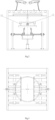
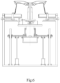
- a high-precision wheel cap section burr removing device is composed of a frame 1, jacking cylinders 2, guide posts 3, a servo motor 4, a lifting table 5, a bearing seat 6, a shaft 7, a bearing 8, a rotating table 9, adjusting guide rails 10, an adjusting cylinder 11, a left sliding table 12, a gear rack 13, a right sliding table 14, pre-positioning cylinders 15, pre-positioning guide rails 16, a sliding plate I 17, a sliding plate II 18, pre-positioning posts 19, corner cylinder pressure claws 20, a left burr cutter 21 and a right burr cutter 22.
- the four pre-positioning guide rails 16 are symmetrically mounted on the frame 1, and the sliding plate 117 and the sliding plate II 18 are respectively mounted on the pre-positioning guide rails 16 and driven by the pre-positioning cylinders 15.
- Two pre-positioning posts 19 are mounted on the sliding plate 117, two pre-positioning posts 19 are also symmetrically mounted on the sliding plate II 18, and the corner cylinder pressure claws 20 are mounted on the pre-positioning posts 19.
- the four pre-positioning posts 19 can pre-position a wheel; and after pre-positioning of the wheel is completed, the left and right pre-positioning cylinders 15 drive the sliding plate I 17 and the sliding plate II 18 to synchronously retract a distance, the four pre-positioning posts 19 do not contact the wheel any more, the clearance is preferably 2-3 mm, and the clearance is reserved for precision positioning.
- the two jacking cylinders 2 and the four guide posts 3 are mounted at the bottom of the frame 1, the output ends of the cylinders are connected with the lifting table 5, the servo motor 4 is mounted on the lifting table 5, the output end of the motor is connected with the rotating table 9 via the shaft 7, the bearing 8 and the bearing seat 6, the rotating table 9 can be driven to move up and down by extension and retraction of the jacking cylinders 2, and the servo motor 4 can drive the rotating table 9 to rotate.
- the two adjusting guide rails 10 are mounted on the rotating table 9, the left sliding table 12 and the right sliding table 14 are symmetrically mounted on the adjusting guide rails 10 and connected by the gear rack 13, the adjusting cylinder 11 is fixed on the side of the rotating table 9, and the output end of the adjusting cylinder 11 is connected with the left sliding table 12.
- the left burr cutter 21 and the right burr cutter 22 are symmetrically mounted on the left sliding table 12 and the right sliding table 14, the top of the left burr cutter 21 is composed of a left precision positioning surface 210 and a left cutting edge 211, and the top of the right burr cutter 22 is composed of a right precision positioning surface 220 and a right cutting edge 221.
- the left precision positioning surface 210 and the right precision positioning surface 220 constitute a precision positioning system
- the left cutting edge 211 and the right cutting edge 221 constitute a cutter system.
- the adjusting cylinder 11 drives the left sliding table 12 and the right sliding table 14 to move synchronously
- the distance between the left precision positioning surface 210 and the right precision positioning surface 220 can be adjusted to match the diameter side of a cap seam allowance, thereby realizing precision positioning; and the distance between the left cutting edge 211 and the right cutting edge 221 can also be adjusted to contact cap section burrs.
- the precision positioning system and the burr removing cutter system are integrated to reduce the combined error, and the rotating centers of the burr cutters are superposed with the central axes of the cap section burrs to realize high-precision burr removal, thereby effectively solving the problems of deviation and non-uniformity of burr removal at the cap section.
- the working process of the device is as follows: firstly, the left and right pre-positioning cylinders 15 are synchronously started to drive the sliding plate I 17 and the sliding plate II 18 to move synchronously, the four pre-positioning posts 19 can pre-position a wheel; and after pre-positioning of the wheel is completed, the pre-positioning cylinders 15 drive the sliding plate 117 and the sliding plate II 18 to synchronously retract a distance, the four pre-positioning posts 19 do not contact the wheel any more, the clearance is preferably 2-3 mm, and the clearance is reserved for precision positioning.
- the jacking cylinders 2 are started to drive the rotating table 9 to ascend; when the positioning surfaces of the left burr cutter 21 and the right burr cutter 22 reach the cap seam allowance of the wheel, the rotating table 9 stops ascending, at the moment, the adjusting cylinder 11 is started to adjust the distance between the left burr cutter 21 and the right burr cutter 22, the left precision positioning surface 210 and the right precision positioning surface 220 contact the diameter side of the cap seam allowance to hold the cap seam allowance of the wheel tightly, and precision positioning of the wheel is thus completed; and after precision positioning of the wheel, the corner cylinder pressure claws 20 are started to press the wheel.
- the adjusting cylinder 11 is continuously started to shorten the distance between the left burr cutter 21 and the right burr cutter 22, the positioning surfaces leave the sides of the cap seam allowance, and then the jacking cylinders 2 are started to drive the burr cutters to ascend; when the cutting edges of the burr cutters reach the height of the cap section burrs, the burr cutters stop ascending, at the moment, the adjusting cylinder 11 is restarted to adjust the distance between the left cutting edge 211 and the right cutting edge 221, and the cutting edges contact the cap section burrs; and finally, the servo motor 4 drives the rotating table 9 to rotate one circle, and the cutting edges of the burr cutters remove the ring of burrs. After the burrs are removed, the positioning system and the cutter system are reset, this is a cyclic working process of the device, and so on.
- the precision positioning system and the burr removing cutter system are integrated to reduce the combined error, and the rotating centers of the burr cutters are superposed with the central axes of the cap section burrs to realize high-precision burr removal, thereby effectively solving the problems of deviation and non-uniformity of burr removal at the cap section.
- the device has the characteristics of novel structure, skillful design, accuracy, high efficiency, simple operation and the like.
Landscapes
- Engineering & Computer Science (AREA)
- Mechanical Engineering (AREA)
- Physics & Mathematics (AREA)
- Optics & Photonics (AREA)
- Milling Processes (AREA)
- Punching Or Piercing (AREA)
Claims (2)
- Hochpräzise Radkappenabschnittsentgratungsvorrichtung, mit einem Gestell (1), an dem vier Vorpositionier-Führungsschienen (16) symmetrisch angebracht sind, wobei an den vier Vorpositionier-Führungsschienen (16) jeweils eine Gleitplatte I (17) und eine Gleitplatte II (18) angebracht sind, die durch Vorpositionierungszylinder (15) angetrieben werden,wobei an der Gleitplatte I (17) zwei Vorpositionierungssäulen (19) angebracht sind, an der Gleitplatte II (18) ebenfalls zwei Vorpositionierungssäulen (19) symmetrisch angebracht sind und an den vier Vorpositionierungssäulen (19) Eckzylinderdruckklauen (20) angebracht sind, wobei die vier Vorpositionierungssäulen (19) ein Rad vorpositionieren können, wenn der linke und der rechte Vorpositionierungszylinder (15) die Gleitplatte I (17) und die Gleitplatte II (18) zur synchronen Bewegung antreiben,wobei an der Unterseite des Gestells (1) Abstützzylinder (2) und vier Führungspfosten (3) angebracht sind, die Ausgangsenden der Zylinder mit einem Hubtisch (5) verbunden sind, ein Servomotor (4) auf dem Hubtisch (5) angebracht ist, das Ausgangsende des Motors über eine Welle (7) , ein Lager (8) und einen Lagersitz (6) mit einem Drehtisch (9) verbunden ist, wobei der Drehtisch (9) durch Ausfahren und Einfahren der Abstützzylinder (2) zur Auf- und Abwärtsbewegung angetrieben werden kann, und der Servomotor (4) den Drehtisch (9) zur Drehung antreiben kann,wobei an dem Drehtisch (9) Verstellführungsschienen (10) angebracht sind, ein linker Gleittisch (12) und ein rechter Gleittisch (14) symmetrisch an den Verstellführungsschienen (10) angebracht und durch eine Zahnstange (13) verbunden sind, wobei ein Verstellzylinder (11) an der Seite des Drehtisches (9) befestigt ist und das Ausgangsende des Verstellzylinders (11) mit dem linken Gleittisch (12) verbunden ist,wobei ein linker Gratschneider (21) und ein rechter Gratschneider (22) symmetrisch auf dem linken Gleittisch (12) und dem rechten Gleittisch (14) angebracht sind, die Oberseite des linken Gratschneiders (21) aus einer linken Präzisionspositionierfläche (210) und einer linken Schneidkante (211) besteht, und die Oberseite des rechten Gratschneiders (22) aus einer rechten Präzisionspositionierfläche (220) und einer rechten Schneidkante (221) besteht,wobei die linke Präzisionspositionierfläche (210) und die rechte Präzisionspositionierfläche (220) ein Präzisionspositioniersystem bilden und die linke Schneidkante (211) und die rechte Schneidkante (221) ein Schneidersystem bilden.
- Hochpräzise Radkappenabschnittsentgratungsvorrichtung nach Anspruch 1, wobei, wenn der Verstellzylinder (11) den linken Gleittisch (12) und den rechten Gleittisch (14) antreibt, um sich synchron zu bewegen, der Abstand zwischen der linken Präzisionspositionierungsfläche (210) und der rechten Präzisionspositionierungsfläche (220) eingestellt werden kann, um mit der Durchmesserseite einer Kappennahtzugabe übereinzustimmen, wodurch eine Präzisionspositionierung realisiert wird; und der Abstand zwischen der linken Schneidkante (211) und der rechten Schneidkante (221) kann auch eingestellt werden, um die Grate des Kappenabschnitts zu berühren, wobei das Präzisionspositionierungssystem und das Gratentfernungsschneidsystem integriert sind, um den kombinierten Fehler zu reduzieren, und die Drehzentren der Gratschneider mit den zentralen Achsen der Grate des Kappenabschnitts überlagert sind, um eine hochpräzise Gratentfernung zu realisieren.
Applications Claiming Priority (1)
| Application Number | Priority Date | Filing Date | Title |
|---|---|---|---|
| CN201710635537.9A CN107283000B (zh) | 2017-07-31 | 2017-07-31 | 一种高精度去车轮帽口毛刺装置 |
Publications (2)
| Publication Number | Publication Date |
|---|---|
| EP3437769A1 EP3437769A1 (de) | 2019-02-06 |
| EP3437769B1 true EP3437769B1 (de) | 2024-06-05 |
Family
ID=60102905
Family Applications (1)
| Application Number | Title | Priority Date | Filing Date |
|---|---|---|---|
| EP18186204.6A Active EP3437769B1 (de) | 2017-07-31 | 2018-07-28 | Hochpräzise entgratungsvorrichtung für radkappenabschnitt |
Country Status (3)
| Country | Link |
|---|---|
| US (1) | US10232454B2 (de) |
| EP (1) | EP3437769B1 (de) |
| CN (1) | CN107283000B (de) |
Families Citing this family (21)
| Publication number | Priority date | Publication date | Assignee | Title |
|---|---|---|---|---|
| CN107717126A (zh) * | 2017-10-31 | 2018-02-23 | 中信戴卡股份有限公司 | 一种用于去除铝合金车轮冒口毛刺的装置 |
| CN107662120A (zh) * | 2017-10-31 | 2018-02-06 | 中信戴卡股份有限公司 | 一种用于铝合金车轮矫正的装置 |
| CN108080744B (zh) * | 2017-12-22 | 2019-09-20 | 中信戴卡股份有限公司 | 一种车轮螺栓孔倒角装置 |
| CN108098496B (zh) | 2017-12-22 | 2023-10-13 | 中信戴卡股份有限公司 | 一种车轮法兰高度差检测及环形槽毛刺清理装置 |
| CN108050923B (zh) | 2017-12-29 | 2019-10-29 | 中信戴卡股份有限公司 | 一种检查车轮法兰面凹凸的装置 |
| CN108057931A (zh) * | 2017-12-29 | 2018-05-22 | 中信戴卡股份有限公司 | 一种去除车轮接刀棱毛刺装置 |
| CN108031929B (zh) * | 2017-12-29 | 2023-11-17 | 中信戴卡股份有限公司 | 一种去除车轮帽口接刀棱毛刺的装置 |
| CN108213594A (zh) * | 2018-01-24 | 2018-06-29 | 中信戴卡股份有限公司 | 一种高精度去车轮圆周毛刺装置 |
| CN108297027B (zh) * | 2018-02-24 | 2023-10-24 | 中信戴卡股份有限公司 | 一种车轮气密胶圈压装装置 |
| CN108705355B (zh) * | 2018-07-31 | 2023-11-03 | 中信戴卡股份有限公司 | 改进车轮加工中心转料定位装置 |
| CN109128262A (zh) * | 2018-08-13 | 2019-01-04 | 泉州睿骋企业管理咨询有限公司 | 一种用于路灯灯头设备 |
| CN109128263A (zh) * | 2018-08-13 | 2019-01-04 | 泉州睿骋企业管理咨询有限公司 | 一种路灯灯头设备 |
| CN109203069A (zh) * | 2018-08-13 | 2019-01-15 | 福建泉州远方致远自动化科技有限公司 | 一种改性abs材料及制备方法与应用 |
| CN109159203A (zh) * | 2018-08-13 | 2019-01-08 | 福建泉州远方致远自动化科技有限公司 | 一种改性abs材料及制备装置 |
| CN109109065A (zh) * | 2018-08-13 | 2019-01-01 | 福建泉州远方致远自动化科技有限公司 | 一种改性abs材料及制备设备 |
| CN109015879A (zh) * | 2018-08-13 | 2018-12-18 | 福建泉州远方致远自动化科技有限公司 | 一种热塑型高分子材料设备 |
| CN109093142A (zh) * | 2018-08-13 | 2018-12-28 | 泉州睿骋企业管理咨询有限公司 | 一种市政探照设备 |
| CN109262399B (zh) * | 2018-11-12 | 2023-09-19 | 中信戴卡股份有限公司 | 一种车轮机加后处理设备 |
| CN110608599A (zh) * | 2019-09-25 | 2019-12-24 | 中信戴卡股份有限公司 | 一种吹水装置 |
| CN110948055B (zh) * | 2019-12-24 | 2020-12-08 | 深圳山源电器股份有限公司 | 一种双面飞翼散热片的加工方法 |
| CN114850582B (zh) * | 2022-05-16 | 2023-12-05 | 中石化石油机械股份有限公司沙市钢管分公司 | 一种用于高频焊管内毛刺打断装置及诊断方法 |
Family Cites Families (12)
| Publication number | Priority date | Publication date | Assignee | Title |
|---|---|---|---|---|
| US2657597A (en) * | 1950-05-25 | 1953-11-03 | George H Pickering | Deburring and chamfering tool |
| GB1439147A (en) * | 1972-09-07 | 1976-06-09 | Dunlop Ltd | Manufacture of vehicle disc wheels |
| US5503508A (en) * | 1994-05-16 | 1996-04-02 | Ellison Machinery Company | Apparatus for, and method of, drilling lug holes and valve stem holes in motor vehicle wheels |
| US6015247A (en) * | 1997-12-17 | 2000-01-18 | Branaman; Vincent E. | Article assembly and alignment machine and method |
| JP2005169517A (ja) * | 2003-12-08 | 2005-06-30 | Sumitomo Electric Hardmetal Corp | バリ取り工具 |
| DE102008014835A1 (de) * | 2008-03-07 | 2009-09-10 | Chiron-Werke Gmbh & Co Kg | Werkzeugmaschine, insbesondere für Felgenbearbeitung |
| CN204234904U (zh) * | 2014-12-09 | 2015-04-01 | 宁波弗莱格液压有限公司 | 一种用于去除深孔内口缘毛刺的刀具 |
| CN105458856B (zh) * | 2015-12-29 | 2017-06-30 | 中信戴卡股份有限公司 | 一种旋转式车轮去毛刺装置 |
| CN105598776B (zh) * | 2016-01-23 | 2017-09-29 | 中信戴卡股份有限公司 | 一种尺寸可调的自适应式车轮在线去毛刺装置 |
| CN105710451A (zh) * | 2016-04-08 | 2016-06-29 | 中信戴卡股份有限公司 | 一种用于去除轮毂轮缘毛刺的装置 |
| CN105881137B (zh) * | 2016-06-01 | 2017-09-29 | 中信戴卡股份有限公司 | 一种套环式车轮去毛刺装置 |
| CN206925404U (zh) * | 2017-07-31 | 2018-01-26 | 中信戴卡股份有限公司 | 一种高精度去车轮帽口毛刺装置 |
-
2017
- 2017-07-31 CN CN201710635537.9A patent/CN107283000B/zh active Active
- 2017-12-14 US US15/842,197 patent/US10232454B2/en active Active
-
2018
- 2018-07-28 EP EP18186204.6A patent/EP3437769B1/de active Active
Also Published As
| Publication number | Publication date |
|---|---|
| CN107283000A (zh) | 2017-10-24 |
| US10232454B2 (en) | 2019-03-19 |
| CN107283000B (zh) | 2024-01-19 |
| US20190030631A1 (en) | 2019-01-31 |
| EP3437769A1 (de) | 2019-02-06 |
Similar Documents
| Publication | Publication Date | Title |
|---|---|---|
| EP3437769A1 (de) | Hochpräzise entgratungsvorrichtung für radkappenabschnitt | |
| US10780545B2 (en) | Device for removing tool joint edge burrs from cap opening of wheel | |
| US20190022815A1 (en) | Automatic wheel front burr removing device | |
| US10737364B2 (en) | Multifunctional wheel burr removing device | |
| EP3479937B1 (de) | Vorrichtung zur korrektur eines aluminiumlegierungsrads | |
| CN201341072Y (zh) | 冲电动机定子片槽形、切气隙兼分离转子片模具 | |
| US10464143B2 (en) | Wheel cap section chamfering device | |
| US10493593B2 (en) | Wheel outer rim fillet dressing device | |
| CN107962262A (zh) | 涡轮盘榫槽电解切割快速成型的电极和加工装置及方法 | |
| CN204194971U (zh) | 一种同步器齿套去毛刺机 | |
| CN216608106U (zh) | 一种模具制造用加工中心数控旋转夹持装置 | |
| CN113664590B (zh) | 一种用于液压阀块加工的数控铣刀及控制方法 | |
| CN112318073A (zh) | 一种刚性磁轭内键槽立式加工工艺方法 | |
| CN221474413U (zh) | 一种立式铣床用定位机构 | |
| CN206925404U (zh) | 一种高精度去车轮帽口毛刺装置 | |
| CN206898401U (zh) | 一种自动去车轮正面毛刺装置 | |
| CN112388038A (zh) | 粗加工转向节四轴面用工装及其加工方法 | |
| CN220575328U (zh) | 一种差速器四轴夹具 | |
| CN111496481A (zh) | 一种大功率高速柴油机机体曲轴孔止推面精密加工方法 | |
| CN214212346U (zh) | 一种粗加工转向节四轴面用工装 | |
| CN213890857U (zh) | —种隔栅模具二次顶出机构 | |
| CN220762532U (zh) | 一种保持架去毛刺用工装夹具 | |
| CN223848975U (zh) | 一种搪瓷搅拌轴加工用夹持固定设备 | |
| CN218985091U (zh) | 一种地板裁切装置 | |
| CN222154510U (zh) | 液压动力元件加工用焊接装置 |
Legal Events
| Date | Code | Title | Description |
|---|---|---|---|
| PUAI | Public reference made under article 153(3) epc to a published international application that has entered the european phase |
Free format text: ORIGINAL CODE: 0009012 |
|
| STAA | Information on the status of an ep patent application or granted ep patent |
Free format text: STATUS: REQUEST FOR EXAMINATION WAS MADE |
|
| 17P | Request for examination filed |
Effective date: 20180728 |
|
| AK | Designated contracting states |
Kind code of ref document: A1 Designated state(s): AL AT BE BG CH CY CZ DE DK EE ES FI FR GB GR HR HU IE IS IT LI LT LU LV MC MK MT NL NO PL PT RO RS SE SI SK SM TR |
|
| AX | Request for extension of the european patent |
Extension state: BA ME |
|
| STAA | Information on the status of an ep patent application or granted ep patent |
Free format text: STATUS: EXAMINATION IS IN PROGRESS |
|
| 17Q | First examination report despatched |
Effective date: 20220222 |
|
| GRAP | Despatch of communication of intention to grant a patent |
Free format text: ORIGINAL CODE: EPIDOSNIGR1 |
|
| STAA | Information on the status of an ep patent application or granted ep patent |
Free format text: STATUS: GRANT OF PATENT IS INTENDED |
|
| INTG | Intention to grant announced |
Effective date: 20240130 |
|
| GRAS | Grant fee paid |
Free format text: ORIGINAL CODE: EPIDOSNIGR3 |
|
| GRAA | (expected) grant |
Free format text: ORIGINAL CODE: 0009210 |
|
| STAA | Information on the status of an ep patent application or granted ep patent |
Free format text: STATUS: THE PATENT HAS BEEN GRANTED |
|
| AK | Designated contracting states |
Kind code of ref document: B1 Designated state(s): AL AT BE BG CH CY CZ DE DK EE ES FI FR GB GR HR HU IE IS IT LI LT LU LV MC MK MT NL NO PL PT RO RS SE SI SK SM TR |
|
| REG | Reference to a national code |
Ref country code: GB Ref legal event code: FG4D |
|
| REG | Reference to a national code |
Ref country code: CH Ref legal event code: EP |
|
| REG | Reference to a national code |
Ref country code: DE Ref legal event code: R096 Ref document number: 602018070246 Country of ref document: DE |
|
| REG | Reference to a national code |
Ref country code: IE Ref legal event code: FG4D |
|
| REG | Reference to a national code |
Ref country code: LT Ref legal event code: MG9D |
|
| PG25 | Lapsed in a contracting state [announced via postgrant information from national office to epo] |
Ref country code: BG Free format text: LAPSE BECAUSE OF FAILURE TO SUBMIT A TRANSLATION OF THE DESCRIPTION OR TO PAY THE FEE WITHIN THE PRESCRIBED TIME-LIMIT Effective date: 20240605 |
|
| REG | Reference to a national code |
Ref country code: NL Ref legal event code: MP Effective date: 20240605 |
|
| PG25 | Lapsed in a contracting state [announced via postgrant information from national office to epo] |
Ref country code: FI Free format text: LAPSE BECAUSE OF FAILURE TO SUBMIT A TRANSLATION OF THE DESCRIPTION OR TO PAY THE FEE WITHIN THE PRESCRIBED TIME-LIMIT Effective date: 20240605 Ref country code: HR Free format text: LAPSE BECAUSE OF FAILURE TO SUBMIT A TRANSLATION OF THE DESCRIPTION OR TO PAY THE FEE WITHIN THE PRESCRIBED TIME-LIMIT Effective date: 20240605 |
|
| PG25 | Lapsed in a contracting state [announced via postgrant information from national office to epo] |
Ref country code: GR Free format text: LAPSE BECAUSE OF FAILURE TO SUBMIT A TRANSLATION OF THE DESCRIPTION OR TO PAY THE FEE WITHIN THE PRESCRIBED TIME-LIMIT Effective date: 20240906 |
|
| PG25 | Lapsed in a contracting state [announced via postgrant information from national office to epo] |
Ref country code: ES Free format text: LAPSE BECAUSE OF FAILURE TO SUBMIT A TRANSLATION OF THE DESCRIPTION OR TO PAY THE FEE WITHIN THE PRESCRIBED TIME-LIMIT Effective date: 20240605 |
|
| PG25 | Lapsed in a contracting state [announced via postgrant information from national office to epo] |
Ref country code: LV Free format text: LAPSE BECAUSE OF FAILURE TO SUBMIT A TRANSLATION OF THE DESCRIPTION OR TO PAY THE FEE WITHIN THE PRESCRIBED TIME-LIMIT Effective date: 20240605 |
|
| PG25 | Lapsed in a contracting state [announced via postgrant information from national office to epo] |
Ref country code: NO Free format text: LAPSE BECAUSE OF FAILURE TO SUBMIT A TRANSLATION OF THE DESCRIPTION OR TO PAY THE FEE WITHIN THE PRESCRIBED TIME-LIMIT Effective date: 20240905 Ref country code: LV Free format text: LAPSE BECAUSE OF FAILURE TO SUBMIT A TRANSLATION OF THE DESCRIPTION OR TO PAY THE FEE WITHIN THE PRESCRIBED TIME-LIMIT Effective date: 20240605 Ref country code: HR Free format text: LAPSE BECAUSE OF FAILURE TO SUBMIT A TRANSLATION OF THE DESCRIPTION OR TO PAY THE FEE WITHIN THE PRESCRIBED TIME-LIMIT Effective date: 20240605 Ref country code: GR Free format text: LAPSE BECAUSE OF FAILURE TO SUBMIT A TRANSLATION OF THE DESCRIPTION OR TO PAY THE FEE WITHIN THE PRESCRIBED TIME-LIMIT Effective date: 20240906 Ref country code: FI Free format text: LAPSE BECAUSE OF FAILURE TO SUBMIT A TRANSLATION OF THE DESCRIPTION OR TO PAY THE FEE WITHIN THE PRESCRIBED TIME-LIMIT Effective date: 20240605 Ref country code: ES Free format text: LAPSE BECAUSE OF FAILURE TO SUBMIT A TRANSLATION OF THE DESCRIPTION OR TO PAY THE FEE WITHIN THE PRESCRIBED TIME-LIMIT Effective date: 20240605 Ref country code: BG Free format text: LAPSE BECAUSE OF FAILURE TO SUBMIT A TRANSLATION OF THE DESCRIPTION OR TO PAY THE FEE WITHIN THE PRESCRIBED TIME-LIMIT Effective date: 20240605 Ref country code: RS Free format text: LAPSE BECAUSE OF FAILURE TO SUBMIT A TRANSLATION OF THE DESCRIPTION OR TO PAY THE FEE WITHIN THE PRESCRIBED TIME-LIMIT Effective date: 20240905 |
|
| PG25 | Lapsed in a contracting state [announced via postgrant information from national office to epo] |
Ref country code: NL Free format text: LAPSE BECAUSE OF FAILURE TO SUBMIT A TRANSLATION OF THE DESCRIPTION OR TO PAY THE FEE WITHIN THE PRESCRIBED TIME-LIMIT Effective date: 20240605 |
|
| REG | Reference to a national code |
Ref country code: AT Ref legal event code: MK05 Ref document number: 1692098 Country of ref document: AT Kind code of ref document: T Effective date: 20240605 |
|
| PG25 | Lapsed in a contracting state [announced via postgrant information from national office to epo] |
Ref country code: NL Free format text: LAPSE BECAUSE OF FAILURE TO SUBMIT A TRANSLATION OF THE DESCRIPTION OR TO PAY THE FEE WITHIN THE PRESCRIBED TIME-LIMIT Effective date: 20240605 |
|
| PG25 | Lapsed in a contracting state [announced via postgrant information from national office to epo] |
Ref country code: PT Free format text: LAPSE BECAUSE OF FAILURE TO SUBMIT A TRANSLATION OF THE DESCRIPTION OR TO PAY THE FEE WITHIN THE PRESCRIBED TIME-LIMIT Effective date: 20241007 |
|
| PG25 | Lapsed in a contracting state [announced via postgrant information from national office to epo] |
Ref country code: PT Free format text: LAPSE BECAUSE OF FAILURE TO SUBMIT A TRANSLATION OF THE DESCRIPTION OR TO PAY THE FEE WITHIN THE PRESCRIBED TIME-LIMIT Effective date: 20241007 |
|
| PG25 | Lapsed in a contracting state [announced via postgrant information from national office to epo] |
Ref country code: PL Free format text: LAPSE BECAUSE OF FAILURE TO SUBMIT A TRANSLATION OF THE DESCRIPTION OR TO PAY THE FEE WITHIN THE PRESCRIBED TIME-LIMIT Effective date: 20240605 |
|
| PG25 | Lapsed in a contracting state [announced via postgrant information from national office to epo] |
Ref country code: EE Free format text: LAPSE BECAUSE OF FAILURE TO SUBMIT A TRANSLATION OF THE DESCRIPTION OR TO PAY THE FEE WITHIN THE PRESCRIBED TIME-LIMIT Effective date: 20240605 |
|
| PG25 | Lapsed in a contracting state [announced via postgrant information from national office to epo] |
Ref country code: AT Free format text: LAPSE BECAUSE OF FAILURE TO SUBMIT A TRANSLATION OF THE DESCRIPTION OR TO PAY THE FEE WITHIN THE PRESCRIBED TIME-LIMIT Effective date: 20240605 Ref country code: IS Free format text: LAPSE BECAUSE OF FAILURE TO SUBMIT A TRANSLATION OF THE DESCRIPTION OR TO PAY THE FEE WITHIN THE PRESCRIBED TIME-LIMIT Effective date: 20241005 |
|
| PG25 | Lapsed in a contracting state [announced via postgrant information from national office to epo] |
Ref country code: CZ Free format text: LAPSE BECAUSE OF FAILURE TO SUBMIT A TRANSLATION OF THE DESCRIPTION OR TO PAY THE FEE WITHIN THE PRESCRIBED TIME-LIMIT Effective date: 20240605 |
|
| PG25 | Lapsed in a contracting state [announced via postgrant information from national office to epo] |
Ref country code: SK Free format text: LAPSE BECAUSE OF FAILURE TO SUBMIT A TRANSLATION OF THE DESCRIPTION OR TO PAY THE FEE WITHIN THE PRESCRIBED TIME-LIMIT Effective date: 20240605 Ref country code: RO Free format text: LAPSE BECAUSE OF FAILURE TO SUBMIT A TRANSLATION OF THE DESCRIPTION OR TO PAY THE FEE WITHIN THE PRESCRIBED TIME-LIMIT Effective date: 20240605 |
|
| PG25 | Lapsed in a contracting state [announced via postgrant information from national office to epo] |
Ref country code: SM Free format text: LAPSE BECAUSE OF FAILURE TO SUBMIT A TRANSLATION OF THE DESCRIPTION OR TO PAY THE FEE WITHIN THE PRESCRIBED TIME-LIMIT Effective date: 20240605 |
|
| PG25 | Lapsed in a contracting state [announced via postgrant information from national office to epo] |
Ref country code: SM Free format text: LAPSE BECAUSE OF FAILURE TO SUBMIT A TRANSLATION OF THE DESCRIPTION OR TO PAY THE FEE WITHIN THE PRESCRIBED TIME-LIMIT Effective date: 20240605 Ref country code: SK Free format text: LAPSE BECAUSE OF FAILURE TO SUBMIT A TRANSLATION OF THE DESCRIPTION OR TO PAY THE FEE WITHIN THE PRESCRIBED TIME-LIMIT Effective date: 20240605 Ref country code: RO Free format text: LAPSE BECAUSE OF FAILURE TO SUBMIT A TRANSLATION OF THE DESCRIPTION OR TO PAY THE FEE WITHIN THE PRESCRIBED TIME-LIMIT Effective date: 20240605 Ref country code: PL Free format text: LAPSE BECAUSE OF FAILURE TO SUBMIT A TRANSLATION OF THE DESCRIPTION OR TO PAY THE FEE WITHIN THE PRESCRIBED TIME-LIMIT Effective date: 20240605 Ref country code: IS Free format text: LAPSE BECAUSE OF FAILURE TO SUBMIT A TRANSLATION OF THE DESCRIPTION OR TO PAY THE FEE WITHIN THE PRESCRIBED TIME-LIMIT Effective date: 20241005 Ref country code: EE Free format text: LAPSE BECAUSE OF FAILURE TO SUBMIT A TRANSLATION OF THE DESCRIPTION OR TO PAY THE FEE WITHIN THE PRESCRIBED TIME-LIMIT Effective date: 20240605 Ref country code: CZ Free format text: LAPSE BECAUSE OF FAILURE TO SUBMIT A TRANSLATION OF THE DESCRIPTION OR TO PAY THE FEE WITHIN THE PRESCRIBED TIME-LIMIT Effective date: 20240605 Ref country code: AT Free format text: LAPSE BECAUSE OF FAILURE TO SUBMIT A TRANSLATION OF THE DESCRIPTION OR TO PAY THE FEE WITHIN THE PRESCRIBED TIME-LIMIT Effective date: 20240605 |
|
| PG25 | Lapsed in a contracting state [announced via postgrant information from national office to epo] |
Ref country code: IT Free format text: LAPSE BECAUSE OF FAILURE TO SUBMIT A TRANSLATION OF THE DESCRIPTION OR TO PAY THE FEE WITHIN THE PRESCRIBED TIME-LIMIT Effective date: 20240605 |
|
| REG | Reference to a national code |
Ref country code: CH Ref legal event code: PL |
|
| REG | Reference to a national code |
Ref country code: DE Ref legal event code: R097 Ref document number: 602018070246 Country of ref document: DE |
|
| PG25 | Lapsed in a contracting state [announced via postgrant information from national office to epo] |
Ref country code: LU Free format text: LAPSE BECAUSE OF NON-PAYMENT OF DUE FEES Effective date: 20240728 |
|
| PG25 | Lapsed in a contracting state [announced via postgrant information from national office to epo] |
Ref country code: MC Free format text: LAPSE BECAUSE OF FAILURE TO SUBMIT A TRANSLATION OF THE DESCRIPTION OR TO PAY THE FEE WITHIN THE PRESCRIBED TIME-LIMIT Effective date: 20240605 |
|
| PG25 | Lapsed in a contracting state [announced via postgrant information from national office to epo] |
Ref country code: MC Free format text: LAPSE BECAUSE OF FAILURE TO SUBMIT A TRANSLATION OF THE DESCRIPTION OR TO PAY THE FEE WITHIN THE PRESCRIBED TIME-LIMIT Effective date: 20240605 Ref country code: LU Free format text: LAPSE BECAUSE OF NON-PAYMENT OF DUE FEES Effective date: 20240728 |
|
| PLBE | No opposition filed within time limit |
Free format text: ORIGINAL CODE: 0009261 |
|
| STAA | Information on the status of an ep patent application or granted ep patent |
Free format text: STATUS: NO OPPOSITION FILED WITHIN TIME LIMIT |
|
| PG25 | Lapsed in a contracting state [announced via postgrant information from national office to epo] |
Ref country code: DK Free format text: LAPSE BECAUSE OF FAILURE TO SUBMIT A TRANSLATION OF THE DESCRIPTION OR TO PAY THE FEE WITHIN THE PRESCRIBED TIME-LIMIT Effective date: 20240605 |
|
| PG25 | Lapsed in a contracting state [announced via postgrant information from national office to epo] |
Ref country code: CH Free format text: LAPSE BECAUSE OF NON-PAYMENT OF DUE FEES Effective date: 20240731 Ref country code: BE Free format text: LAPSE BECAUSE OF NON-PAYMENT OF DUE FEES Effective date: 20240731 |
|
| 26N | No opposition filed |
Effective date: 20250306 |
|
| GBPC | Gb: european patent ceased through non-payment of renewal fee |
Effective date: 20240905 |
|
| REG | Reference to a national code |
Ref country code: BE Ref legal event code: MM Effective date: 20240731 |
|
| PG25 | Lapsed in a contracting state [announced via postgrant information from national office to epo] |
Ref country code: GB Free format text: LAPSE BECAUSE OF NON-PAYMENT OF DUE FEES Effective date: 20240905 |
|
| PG25 | Lapsed in a contracting state [announced via postgrant information from national office to epo] |
Ref country code: IE Free format text: LAPSE BECAUSE OF NON-PAYMENT OF DUE FEES Effective date: 20240728 |
|
| PG25 | Lapsed in a contracting state [announced via postgrant information from national office to epo] |
Ref country code: SE Free format text: LAPSE BECAUSE OF FAILURE TO SUBMIT A TRANSLATION OF THE DESCRIPTION OR TO PAY THE FEE WITHIN THE PRESCRIBED TIME-LIMIT Effective date: 20240605 |
|
| PGFP | Annual fee paid to national office [announced via postgrant information from national office to epo] |
Ref country code: DE Payment date: 20250711 Year of fee payment: 8 |
|
| PGFP | Annual fee paid to national office [announced via postgrant information from national office to epo] |
Ref country code: FR Payment date: 20250730 Year of fee payment: 8 |
|
| PG25 | Lapsed in a contracting state [announced via postgrant information from national office to epo] |
Ref country code: CY Free format text: LAPSE BECAUSE OF FAILURE TO SUBMIT A TRANSLATION OF THE DESCRIPTION OR TO PAY THE FEE WITHIN THE PRESCRIBED TIME-LIMIT; INVALID AB INITIO Effective date: 20180728 |
|
| VS25 | Lapsed in a validation state [announced via postgrant information from nat. office to epo] |
Ref country code: MA Free format text: FAILURE TO ELECT DOMICILE IN THE NATIONAL COUNTRY Effective date: 20240906 |
|
| PG25 | Lapsed in a contracting state [announced via postgrant information from national office to epo] |
Ref country code: HU Free format text: LAPSE BECAUSE OF FAILURE TO SUBMIT A TRANSLATION OF THE DESCRIPTION OR TO PAY THE FEE WITHIN THE PRESCRIBED TIME-LIMIT; INVALID AB INITIO Effective date: 20180728 |
|
| VS25 | Lapsed in a validation state [announced via postgrant information from nat. office to epo] |
Ref country code: MA Free format text: LAPSE BECAUSE OF FAILURE TO SUBMIT A TRANSLATION OF THE DESCRIPTION OR TO PAY THE FEE WITHIN THE PRESCRIBED TIME-LIMIT Effective date: 20240605 |