EP3436320B1 - Bremskraftsimulator für ein kraftfahrzeug - Google Patents
Bremskraftsimulator für ein kraftfahrzeug Download PDFInfo
- Publication number
- EP3436320B1 EP3436320B1 EP17705384.0A EP17705384A EP3436320B1 EP 3436320 B1 EP3436320 B1 EP 3436320B1 EP 17705384 A EP17705384 A EP 17705384A EP 3436320 B1 EP3436320 B1 EP 3436320B1
- Authority
- EP
- European Patent Office
- Prior art keywords
- elastomer element
- axial stop
- braking force
- piston
- force simulator
- Prior art date
- Legal status (The legal status is an assumption and is not a legal conclusion. Google has not performed a legal analysis and makes no representation as to the accuracy of the status listed.)
- Active
Links
- 229920001971 elastomer Polymers 0.000 claims description 68
- 239000000806 elastomer Substances 0.000 claims description 68
- 238000006073 displacement reaction Methods 0.000 claims description 11
- 229920002635 polyurethane Polymers 0.000 claims description 6
- 239000004814 polyurethane Substances 0.000 claims description 6
- 229920002943 EPDM rubber Polymers 0.000 claims description 4
- 238000011161 development Methods 0.000 description 4
- 230000018109 developmental process Effects 0.000 description 4
- 238000004519 manufacturing process Methods 0.000 description 3
- 239000000463 material Substances 0.000 description 3
- 238000000034 method Methods 0.000 description 3
- ZJNBWGXJBUTVBW-UHFFFAOYSA-N CCC1C(CC2)C2SC1 Chemical compound CCC1C(CC2)C2SC1 ZJNBWGXJBUTVBW-UHFFFAOYSA-N 0.000 description 1
- 238000000418 atomic force spectrum Methods 0.000 description 1
- 230000008878 coupling Effects 0.000 description 1
- 238000010168 coupling process Methods 0.000 description 1
- 238000005859 coupling reaction Methods 0.000 description 1
- 230000000694 effects Effects 0.000 description 1
- 238000009434 installation Methods 0.000 description 1
- 238000007789 sealing Methods 0.000 description 1
Images


Classifications
-
- B—PERFORMING OPERATIONS; TRANSPORTING
- B60—VEHICLES IN GENERAL
- B60T—VEHICLE BRAKE CONTROL SYSTEMS OR PARTS THEREOF; BRAKE CONTROL SYSTEMS OR PARTS THEREOF, IN GENERAL; ARRANGEMENT OF BRAKING ELEMENTS ON VEHICLES IN GENERAL; PORTABLE DEVICES FOR PREVENTING UNWANTED MOVEMENT OF VEHICLES; VEHICLE MODIFICATIONS TO FACILITATE COOLING OF BRAKES
- B60T8/00—Arrangements for adjusting wheel-braking force to meet varying vehicular or ground-surface conditions, e.g. limiting or varying distribution of braking force
- B60T8/32—Arrangements for adjusting wheel-braking force to meet varying vehicular or ground-surface conditions, e.g. limiting or varying distribution of braking force responsive to a speed condition, e.g. acceleration or deceleration
- B60T8/34—Arrangements for adjusting wheel-braking force to meet varying vehicular or ground-surface conditions, e.g. limiting or varying distribution of braking force responsive to a speed condition, e.g. acceleration or deceleration having a fluid pressure regulator responsive to a speed condition
- B60T8/40—Arrangements for adjusting wheel-braking force to meet varying vehicular or ground-surface conditions, e.g. limiting or varying distribution of braking force responsive to a speed condition, e.g. acceleration or deceleration having a fluid pressure regulator responsive to a speed condition comprising an additional fluid circuit including fluid pressurising means for modifying the pressure of the braking fluid, e.g. including wheel driven pumps for detecting a speed condition, or pumps which are controlled by means independent of the braking system
- B60T8/4072—Systems in which a driver input signal is used as a control signal for the additional fluid circuit which is normally used for braking
- B60T8/4081—Systems with stroke simulating devices for driver input
- B60T8/409—Systems with stroke simulating devices for driver input characterised by details of the stroke simulating device
-
- B—PERFORMING OPERATIONS; TRANSPORTING
- B60—VEHICLES IN GENERAL
- B60T—VEHICLE BRAKE CONTROL SYSTEMS OR PARTS THEREOF; BRAKE CONTROL SYSTEMS OR PARTS THEREOF, IN GENERAL; ARRANGEMENT OF BRAKING ELEMENTS ON VEHICLES IN GENERAL; PORTABLE DEVICES FOR PREVENTING UNWANTED MOVEMENT OF VEHICLES; VEHICLE MODIFICATIONS TO FACILITATE COOLING OF BRAKES
- B60T7/00—Brake-action initiating means
- B60T7/02—Brake-action initiating means for personal initiation
- B60T7/04—Brake-action initiating means for personal initiation foot actuated
- B60T7/06—Disposition of pedal
-
- B—PERFORMING OPERATIONS; TRANSPORTING
- B60—VEHICLES IN GENERAL
- B60T—VEHICLE BRAKE CONTROL SYSTEMS OR PARTS THEREOF; BRAKE CONTROL SYSTEMS OR PARTS THEREOF, IN GENERAL; ARRANGEMENT OF BRAKING ELEMENTS ON VEHICLES IN GENERAL; PORTABLE DEVICES FOR PREVENTING UNWANTED MOVEMENT OF VEHICLES; VEHICLE MODIFICATIONS TO FACILITATE COOLING OF BRAKES
- B60T8/00—Arrangements for adjusting wheel-braking force to meet varying vehicular or ground-surface conditions, e.g. limiting or varying distribution of braking force
- B60T8/32—Arrangements for adjusting wheel-braking force to meet varying vehicular or ground-surface conditions, e.g. limiting or varying distribution of braking force responsive to a speed condition, e.g. acceleration or deceleration
- B60T8/34—Arrangements for adjusting wheel-braking force to meet varying vehicular or ground-surface conditions, e.g. limiting or varying distribution of braking force responsive to a speed condition, e.g. acceleration or deceleration having a fluid pressure regulator responsive to a speed condition
- B60T8/40—Arrangements for adjusting wheel-braking force to meet varying vehicular or ground-surface conditions, e.g. limiting or varying distribution of braking force responsive to a speed condition, e.g. acceleration or deceleration having a fluid pressure regulator responsive to a speed condition comprising an additional fluid circuit including fluid pressurising means for modifying the pressure of the braking fluid, e.g. including wheel driven pumps for detecting a speed condition, or pumps which are controlled by means independent of the braking system
- B60T8/4072—Systems in which a driver input signal is used as a control signal for the additional fluid circuit which is normally used for braking
- B60T8/4081—Systems with stroke simulating devices for driver input
- B60T8/4086—Systems with stroke simulating devices for driver input the stroke simulating device being connected to, or integrated in the driver input device
-
- C—CHEMISTRY; METALLURGY
- C08—ORGANIC MACROMOLECULAR COMPOUNDS; THEIR PREPARATION OR CHEMICAL WORKING-UP; COMPOSITIONS BASED THEREON
- C08L—COMPOSITIONS OF MACROMOLECULAR COMPOUNDS
- C08L23/00—Compositions of homopolymers or copolymers of unsaturated aliphatic hydrocarbons having only one carbon-to-carbon double bond; Compositions of derivatives of such polymers
- C08L23/02—Compositions of homopolymers or copolymers of unsaturated aliphatic hydrocarbons having only one carbon-to-carbon double bond; Compositions of derivatives of such polymers not modified by chemical after-treatment
- C08L23/16—Elastomeric ethene-propene or ethene-propene-diene copolymers, e.g. EPR and EPDM rubbers
-
- C—CHEMISTRY; METALLURGY
- C08—ORGANIC MACROMOLECULAR COMPOUNDS; THEIR PREPARATION OR CHEMICAL WORKING-UP; COMPOSITIONS BASED THEREON
- C08L—COMPOSITIONS OF MACROMOLECULAR COMPOUNDS
- C08L75/00—Compositions of polyureas or polyurethanes; Compositions of derivatives of such polymers
- C08L75/04—Polyurethanes
Definitions
- the invention relates to a braking force simulator for a motor vehicle, with a piston which is operatively connected / operatively connected to an actuatable brake pedal of the motor vehicle and axially displaceably guided in a cylinder, with at least one spring element being arranged in the cylinder, which allows the movement of the piston in one direction counteracts with a spring force.
- the invention also relates to a braking device with such a braking force simulator.
- Master brake cylinders are used in hydraulic brake systems of motor vehicles in order to translate the braking force mechanically applied by a driver into the hydraulic brake system.
- the brake pedal device is coupled to a piston that is displaceably mounted in the master brake cylinder.
- a hydraulic pressure is generated in a first pressure chamber, which is then built up in the brake circuit connected to the master brake cylinder in order to hydraulically actuate one or more wheel brakes of the brake device.
- Known braking force simulators have a spring element which counteracts the braking force applied by the driver.
- the spring element is assigned to a piston that can be displaced by the brake pedal, so that the driver moves the piston against the spring force of the spring element when the brake pedal is actuated and thereby tensions the spring element.
- the spring element is usually designed as a metallic helical spring.
- a braking force simulator which has an elastomer element as a spring element.
- a similar braking force simulator is also the Offenlegungsschrift U.S. 5,729,979 A as well as from the published documents DE 196 51153 A1 , JP 2006-256408 A , EP 2 168 824 A1 and JP 2010-000925 A already known.
- the braking force simulator according to the invention with the features of claim 1 has the advantage that an improved force-displacement characteristic curve of the braking force simulator is achieved, which gives the driver improved haptic feedback during a braking process.
- this is achieved in that the spring element is designed as an elastomer element.
- desired elastic properties of the spring element can be achieved in an even more targeted manner, in particular also through different geometries of the spring element, which are advantageous for the braking feeling. Due to the design as an elastomer element, these variants are inexpensive and can be implemented with little manufacturing effort.
- the elastomer element can be a simple way Replace the existing spring element so that the braking force simulator can also be adjusted later.
- the elastomer element is made at least essentially from ethylene-propylene-diene rubber and / or from polyurethane.
- polyurethane has the advantage that the haptic feedback to a driver remains the same even with higher temperature changes. The material is relatively independent of temperature.
- the elastomer element made of polyurethane has only a very small transverse expansion when compressed, so that the use of the elastomer element made of polyurethane has advantages with regard to the required installation space.
- Ethylene-propylene-diene rubber on the other hand, has the advantage of being inexpensive to manufacture and being highly resilient.
- the elastomer element is cylindrical and is arranged coaxially in the cylinder.
- the longitudinal axis of the elastomer element thus extends in the direction of movement of the piston, so that the elastomer element is compressed axially when the piston is actuated and, if necessary, expanded radially.
- the elastomer element is therefore also advantageously guided or can be guided in the cylinder so that, for example, jamming of the elastomer element is reliably prevented.
- the elastomer element is additionally assigned a conventional helical spring for support, which further advantageously influences the force-displacement characteristic of the braking force simulator.
- the first end of the elastomer element rests flat against a bottom of the cylinder.
- the elastomer element thus has a large contact area on the floor, on which it is supported, as a result of which, in particular, high forces can be transmitted from the piston to the elastomer element.
- a second end of the elastomer element is flat and orthogonal to the longitudinal axis of the elastomer element is formed.
- the elastomer element is thus designed as a cylinder overall.
- the end face of the first end is expediently designed to be flat and orthogonal to the longitudinal axis of the elastomer element in order to ensure a stable contact surface.
- the second end is designed in the shape of a truncated cone. This results in an advantageous deformation or an advantageous force curve when the piston acts on the elastomer element, which optimizes the force-displacement characteristic of the braking force simulator. What is achieved in particular is that at the beginning of the movement of the piston, a lower spring force counteracts the force of the spring element, which increases as the movement path increases.
- the second end of the elastomer element is spherical.
- this does not result in a flat contact point on the piston, but rather a contact point at which the piston touches the spherical shape.
- This also results in an advantageous force-displacement characteristic of the braking force simulator.
- the second end preferably has a cylindrical projection, at the end of which the spherical shape is formed. This has a further advantageous effect on the behavior of the braking force simulator. In particular, this results in a first axial stop surface on the spherical shape and a second axial stop surface on the other end of the elastomer element, which will be discussed again later.
- the second end of the elastomer element has a depression, in particular a concave curvature.
- the elastomer element thus has an annular contact surface which is used to contact the piston.
- the elastomer element has a radial taper underneath the recess, so that a disk-shaped or plate-shaped second end of the elastomer element is formed.
- the plate shape ensures that the spring force that acts in the first place is particularly low and then suddenly as the piston moves or is increased suddenly when the plate-shaped section has been deformed to the maximum.
- the elastomer element has a first axial stop surface and at least one second axial stop surface for the piston at its second end.
- a projection is formed on the end face of the second end, which protrudes from the end face and has a diameter that is smaller than that of the rest of the elastomer element, as already mentioned above. This results in a first axial stop surface at the tip of the projection and a second axial stop surface on the free end face or the remaining free end face at the second end of the elastomer element.
- the piston has a first axial stop for the first axial stop surface and a second axial stop for the second axial stop surface.
- the first axial stop and the second axial stop and the first axial stop surface and the second axial stop surface are each axially spaced from one another.
- the second axial stop surface and the second axial stop are thus arranged axially offset from the first axial stop surface and the second axial stop, respectively, so that the second axial stop and the second axial stop surface only touch takes place at the desired point in time or at a certain displacement path of the piston.
- the elastomer element is designed as a sleeve element and thus has an axially continuous cavity. This saves material and weight, and depending on the choice of material of the elastomer element and depending on the application, the resulting reduced spring force of the elastomer element, which counteracts the piston, is still sufficient.
- the previously mentioned additional helical spring is guided in the cavity of the sleeve element.
- the braking device according to the invention with the features of claim 9 is characterized by the braking force simulator according to the invention. This results in the advantages already mentioned. Further advantages and preferred features and combinations of features emerge in particular from what has been described above and from the claims.
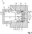
- Figure 1 shows, in a simplified longitudinal sectional illustration, a braking force simulator 1 of a braking device of a motor vehicle, not shown in detail here.
- the braking force simulator 1 is designed to be used in the braking device designed as a hydraulically operating system.
- the braking force simulator 1 has a cylinder 2 in which a piston 3 is arranged such that it can be axially displaced.
- the piston 3 is also arranged guided by at least one sealing ring 4 radially on the outside close to the inner wall of the cylinder 2. Hydraulic medium can be conveyed into the cylinder through a pressure connection 5, as a result of which the piston 3 is axially displaced into the cylinder 2.
- the pressure connection 5 is, for example, hydraulically coupled to a master brake cylinder of the braking device.
- the piston 3, as shown by dashed lines, is mechanically coupled to a brake pedal of the braking device, so that the piston 3 is displaced in the cylinder 2 by mechanical actuation.
- the spring element 6 which is supported on a base 7 of the cylinder 2 on the one hand and on the piston 3 on the other hand, so that it can be elastically braced between these two. If a braking force is applied to the piston 3 hydraulically or mechanically by the driver of the motor vehicle, it is moved against the spring element 6 so that the spring force made available by the spring element 6 counteracts the movement of the piston 3.
- the spring element 6 is designed as an elastomer element 8, which is made in particular from polyurethane or from ethylene-propylene-diene rubber.
- the elastomer element 8 is cylindrical and for this purpose has a first section I with a frustoconical contour and a second section II with a frustoconical contour, seen in longitudinal section.
- the first section I forms a first end 9 which is supported on the cylinder 2 or on its base 7.
- the second section II protruding from the first section I forms a second end 10 which is assigned to the piston 3.
- the end face 11 of the elastomer element 8 is flat at the first end 9 and is orthogonal to the longitudinal center axis of the elastomer element 8, so that the first end 9 rests flat on the base 7 of the cylinder 2.
- the remaining end face 12 of the elastomer element 8, which is assigned to the piston 3, is spherical and thus lies in the position shown in FIG Figure 1 Starting position shown with only a small area or punctiform on the piston 3.
- the end face 12 forms a first axial stop surface 13 which increases in size as a function of the contact pressure of the piston 3 or of the displacement path of the piston 3. Because section II overall has a smaller diameter than first section I of elastomer element 8, this also forms a second axial stop surface 14, which lies radially outside first stop surface 13.
- the piston 3 On its side facing the elastomer element 8, the piston 3 has a step-shaped recess which has a first axial stop 16 in the center and, radially on the outside, a second axial stop 17 which is assigned to the second axial stop surface 14 in such a way that when the piston 3 accordingly is moved far in the direction of the elastomer element 8, the second axial stop 17 hits the second axial stop surface 14.
- this provides a pedal force simulator 1 which has an advantageous force-displacement characteristic and is also designed to save space and ensure a long service life.
- Figures 2 to 4 show different exemplary embodiments of the elastomer element 8 not according to the invention, each in a side view and in a perspective illustration.
- Figures 2A and 2B show the elastomer element 8 according to a first exemplary embodiment not according to the invention, in which the elastomer element 8 is designed overall as a cylinder body. This represents a particularly cost-effective embodiment.
- the piston 3 is expediently adapted to the shape of the elastomer element 8 in such a way that it comes flat with the end face 12 on the piston 3 or is already pretensioned in the starting position.
- Figures 3A and 3B show a second exemplary embodiment not according to the invention, in which the first section I is cylindrical and the second section II of the elastomer element 8 is designed in the shape of a truncated cone.
- the elastomer element 8 thus also has a flat end face 12 for contact with the piston 3, but due to the frustoconical design of the section 2, it ensures an improved spring force-displacement characteristic curve of the elastomer element 8, particularly with a small movement path of the piston 3 starting from its Starting position according to Figure 1 must first use a low spring force.
- Figures 4A and 4B show a further exemplary embodiment of the elastomer element 8 not according to the invention, which, according to this exemplary embodiment, is sleeve-shaped with an axially continuous cavity 18.
- the first section I is again cylindrical.
- the second section II has on the end face 12 a depression 19 in the form of a concave bulge.
- the elastomer element 8 also has a diameter or radial taper 20, as a result of which the end 10 facing the piston 3 is given the shape of a disc spring.
- the cavity 18 can be used, for example, to arrange and guide an additional helical spring in the pedal force simulator 1, which provides an additional spring force acting on the piston 3.
Landscapes
- Engineering & Computer Science (AREA)
- Physics & Mathematics (AREA)
- Fluid Mechanics (AREA)
- Transportation (AREA)
- Mechanical Engineering (AREA)
- Chemical & Material Sciences (AREA)
- Health & Medical Sciences (AREA)
- Chemical Kinetics & Catalysis (AREA)
- Medicinal Chemistry (AREA)
- Polymers & Plastics (AREA)
- Organic Chemistry (AREA)
- Regulating Braking Force (AREA)
- Braking Systems And Boosters (AREA)
- Braking Elements And Transmission Devices (AREA)
Description
- Die Erfindung betrifft einen Bremskraftsimulator für ein Kraftfahrzeug, mit einem Kolben, der mit einem betätigbaren Bremspedal des Kraftfahrzeugs wirkverbunden/wirkverbindbar und in einem Zylinder axial verlagerbar geführt ist, wobei in dem Zylinder wenigstens ein Federelement angeordnet ist, das der Bewegung des Kolbens in eine Richtung mit einer Federkraft entgegen wirkt.
- Ferner betrifft die Erfindung eine Bremseinrichtung mit einem derartigen Bremskraftsimulator.
- Bremskraftsimulatoren und Bremseinrichtungen der eingangs genannten Art sind aus dem Stand der Technik bekannt. In hydraulischen Bremssystemen von Kraftfahrzeugen werden Hauptbremszylinder eingesetzt, um die von einem Fahrer mechanisch aufgebrachte Bremskraft in das hydraulische Bremssystem zu übersetzen. Dazu ist die Bremspedaleinrichtung mit einem in dem Hauptbremszylinder verschiebbar gelagerten Kolben gekoppelt. Durch das Verschieben wird in einer ersten Druckkammer ein hydraulischer Druck erzeugt, der dann in dem mit dem Hauptbremszylinder verbundenen Bremskreis aufgebaut wird, um eine oder mehrere Radbremsen der Bremseinrichtung hydraulisch zu betätigen. Aktuelle Entwicklungen sehen vor, dass die Bremskraft in Radbremsen nicht mehr direkt durch den Fahrer, sondern vielmehr durch elektrisch ansteuerbare Aktuatoren bereitgestellt wird, die dann die jeweilige Bremskraft elektromotorisch oder elektrohydraulisch an den Radbremsen zur Verfügung stellen. Bei einem solchen Bremssystem, bei dem die direkte mechanische/hydraulische Kopplung zwischen Bremspedal und Radbremse unterbrochen ist, fehlt für den Fahrer eine fühlbare Rückmeldung am Bremspedal über die von ihm aufgebrachte Bremskraft. Damit fällt dem Fahrer ein sensibles Betätigen des Bremspedals besonders schwer. Damit der Fahrer nicht das Gefühl für den Bremsvorgang verliert, sind daher Bremskraftsimulatoren, die auch Pedalgefühlssimulatoren genannt werden, bekannt, die dem Fahrer trotz der Trennung der direkten Verbindung ein Gefühl beziehungsweise ein Feedback über die von ihm eingeleitete Bremskraft geben. Bekannte Bremskraftsimulatoren weisen ein Federelement auf, das der durch den Fahrer aufgebrachten Bremskraft entgegenwirkt. Dazu ist das Federelement einem durch das Bremspedal verlagerbaren Kolben zugeordnet, sodass der Fahrer beim Betätigen des Bremspedals den Kolben entgegen der Federkraft des Federelements bewegt und dadurch das Federelement spannt. Üblicherweise ist das Federelement als metallische Schraubenfeder ausgebildet. Damit erhöht sich der Gegendruck für den Fahrer mit dem Bewegungsweg des Kolbens spürbar, wodurch er ein Gefühl für den Bremsvorgang erhält.
- Aus der Offenlegungsschrift
WO 2015/104122 A1 ist bereits ein Bremskraftsimulator bekannt, der als Federelement ein Elastomerelement aufweist. Ein ähnlicher Bremskraftsimulator ist auch der OffenlegungsschriftUS 5,729,979 A sowie aus den OffenlegungsschriftenDE 196 51153 A1 ,JP 2006-256408 A EP 2 168 824 A1 undJP 2010-000925 A - Der erfindungsgemäße Bremskraftsimulator mit den Merkmalen des Anspruchs 1 hat den Vorteil, dass eine verbesserte Kraft-Weg-Kennlinie des Bremskraftsimulators erzielt wird, welche dem Fahrer ein verbessertes haptisches Feedback bei einem Bremsvorgang vermittelt. Erfindungsgemäß wird dies dadurch erreicht, dass das Federelement als Elastomerelement ausgebildet ist. Dadurch lassen sich gewünschte elastische Eigenschaften des Federelements noch gezielter erreichen, insbesondere auch durch unterschiedliche Geometrien des Federelements, welche vorteilhaft für das Bremsgefühl sind. Durch die Ausbildung als Elastomerelement sind diese Varianten kostengünstig und mit einem geringen Herstellungsaufwand realisierbar. Das Elastomerelement kann dabei auf einfache Art und Weise ein bereits bestehendes Federelement ersetzen, sodass auch eine nachträgliche Anpassung des Bremskraftsimulators möglich ist.
- Bevorzugt ist vorgesehen, dass das Elastomerelement zumindest im Wesentlichen aus Ethylen-Propylen-Dien-Kautschuk und/oder aus Polyurethan gefertigt ist. Durch die Verwendung von Polyurethan wird der Vorteil erreicht, dass auch bei höheren Temperaturveränderungen die haptische Rückmeldung an einen Fahrer gleich bleibt. Das Material ist verhältnismäßig temperaturunabhängig. Darüber hinaus weist das Elastomerelement aus Polyurethan bei Stauchung eine nur sehr geringe Querdehnung auf, sodass die Verwendung des Elastomerelements aus Polyurethan Vorteile in Bezug auf den notwendigen Bauraum aufweist. Ethylen-Propylen-Dien-Kautschuk hat hingegen den Vorteil einer kostengünstigen Fertigung und einer hohen Belastbarkeit.
- Gemäß einer bevorzugten Weiterbildung der Erfindung ist vorgesehen, dass das Elastomerelement zylinderförmig ausgebildet und koaxial in dem Zylinder angeordnet ist. Die Längsachse des Elastomerelements erstreckt sich somit in Bewegungsrichtung des Kolbens, sodass das Elastomerelement axial bei einer Betätigung des Kolbens gestaucht und gegebenenfalls radial gedehnt wird. Das Elastomerelement ist damit außerdem vorteilhaft auch in dem Zylinder geführt beziehungsweise führbar, sodass beispielsweise ein Verklemmen des Elastomerelements sicher verhindert ist. Dadurch ist die Herstellung des Elastomerelements besonders einfach und kostengünstig. Auch ist eine Fehlmontage des Elastomerelements in dem Bremskraftsimulator nicht möglich. Optional ist vorgesehen, dass dem Elastomerelement zusätzlich eine herkömmliche Schraubenfeder zur Unterstützung zugeordnet ist, welche die Kraft-Weg-Kennlinie des Bremskraftsimulators weiter vorteilhaft beeinflusst.
- Erfindungsgemäß ist vorgesehen, dass das Elastomerelement mit einem ersten Ende flächig an einem Boden des Zylinders anliegt. Damit weist das Elastomerelement eine große Aufstandsfläche auf dem Boden auf, an welcher es sich abstützt, wodurch insbesondere hohe Kräfte von dem Kolben auf das Elastomerelement übertragen werden können.
Gemäß einer nicht erfindungsgemäßen Ausführungsform ist vorgesehen, dass ein zweites Ende des Elastomerelements eben und orthogonal zur Längsachse des Elastomerelements ausgebildet ist. Damit ist das Elastomerelement insgesamt als Zylinder ausgebildet. Zweckmäßigerweise ist die Stirnseite des ersten Endes eben und orthogonal zur Längsachse des Elastomerelements ausgebildet, um eine stabile Aufstandsfläche zu gewährleisten. - Gemäß einer nicht erfindungsgemäßen Ausführungsform ist vorgesehen, dass das zweite Ende kegelstumpfförmig ausgebildet ist. Dadurch ergibt sich bei der Beaufschlagung des Elastomerelements durch den Kolben eine vorteilhafte Verformung beziehungsweise ein vorteilhafter Kraftverlauf, der die Kraft-Weg-Kennlinie des Bremskraftsimulators optimiert. Insbesondere wird dadurch erreicht, dass zu Beginn der Bewegung des Kolbens entgegen der Kraft des Federelements eine geringere Federkraft entgegenwirkt, die mit zunehmendem Bewegungsweg zunimmt.
- Weiterhin ist bevorzugt alternativ vorgesehen, dass das zweite Ende des Elastomerelements kugelförmig ausgebildet ist. Dadurch ergibt sich an dem Kolben insbesondere keine flächige Auflagestelle, sondern zunächst ein Auflagepunkt, an welchem der Kolben die Kugelform berührt. Hierdurch ergibt sich ebenfalls eine vorteilhafte Kraft-Weg-Kennlinie des Bremskraftsimulators. Vorzugsweise weist das zweite Ende einen zylinderförmigen Vorsprung auf, an dessen Ende die Kugelform ausgebildet ist. Dadurch wird das Verhalten des Bremskraftsimulators weiter vorteilhaft beeinflusst. Insbesondere ergeben sich dadurch eine erste Axialanschlagsfläche an der Kugelform und eine zweite Axialanschlagsfläche an dem anderen Ende des Elastomerelements, worauf später nochmals näher eingegangen wird.
- Gemäß einer bevorzugten Weiterbildung der Erfindung ist alternativ vorgesehen, dass das zweite Ende des Elastomerelements eine Vertiefung, insbesondere eine konkav ausgebildete Wölbung aufweist. Damit weist das Elastomerelement eine ringförmige Kontaktfläche auf, welche zum Kontaktieren des Kolbens dient. Insbesondere ist vorgesehen, dass das Elastomerelement eine radiale Verjüngung unterhalb der Vertiefung aufweist, sodass ein scheibenförmiges oder tellerförmiges zweites Ende des Elastomerelements gebildet ist. Durch die Tellerform wird erreicht, dass die zuerst entgegenwirkende Federkraft besonders gering ist und dann mit zunehmendem Bewegungsweg des Kolbens plötzlich oder schlagartig erhöht wird, wenn der tellerförmige Abschnitt maximal verformt wurde.
- Erfindungsgemäß ist vorgesehen, dass das Elastomerelement an seinem zweiten Ende eine erste Axialanschlagsfläche und wenigstens eine zweite Axialanschlagsfläche für den Kolben aufweist. Dies wird beispielsweise dadurch erreicht, dass an der Stirnseite des zweiten Endes ein Vorsprung ausgebildet ist, der von der Stirnseite vorsteht und einen Durchmesser aufweist, der kleiner ist als der des übrigen Elastomerelements, wie zuvor bereits erwähnt. Dadurch ergibt sich eine erste Axialanschlagsfläche an der Spitze des Vorsprungs und eine zweite Axialanschlagsfläche an der freien Stirnseite beziehungsweise der verbleibenden freien Stirnseite am zweiten Ende des Elastomerelements. Hierdurch wird beispielsweise erreicht, dass der Kolben bei seiner Betätigung zunächst nur eine Kraft über die erste Axialanschlagsfläche auf das Elastomerelement ausüben kann, und mit zunehmendem Bewegungsweg irgendwann auf die zweite Axialanschlagsfläche trifft und dann auch über diese eine weitere Kraft übertragen kann. Entsprechend erhöht sich die dem Kolben entgegenwirkende Federkraft zu dem Zeitpunkt, an welchem dieser auch die zweite Axialanschlagsfläche kontaktiert. Dadurch ist eine schlagartige Erhöhung der dem Kolben entgegenwirkenden Federkraft realisierbar.
- Weiterhin ist erfindungsgemäß vorgesehen, dass der Kolben einen ersten Axialanschlag für die erste Axialanschlagsfläche und einen zweiten Axialänschlag für die zweite Axialanschlagsfläche aufweist. Durch die Ausbildung definierter Axialanschläge für die axialen Anschlagsflächen wird das Verhältnis zwischen Bewegungsweg und entgegenwirkender Federkraft genau definiert, wodurch sich weitere Vorteile bezüglich der Kraft-Weg-Kennlinie ergeben.
- Erfindungsgemäß ist dazu vorgesehen, dass der erste Axialanschlag und der zweite Axialanschlag und die erste Axialanschlagsfläche und die zweite Axialanschlagsfläche jeweils axial beabstandet zueinander ausgebildet sind. Damit ist insbesondere jeweils die zweite Axialanschlagsfläche und der zweite Axialanschlag axial versetzt zu der ersten axialen Anschlagsfläche beziehungsweise dem zweiten Axialanschlag angeordnet, sodass eine Berührung von zweitem Axialanschlag und zweiter axialer Anschlagsfläche erst den gewünschten Zeitpunkt beziehungsweise zu einem bestimmten Verschiebungsweg des Kolbens erfolgt.
- Gemäß einer nicht erfindungsgemäßen Weiterbildung ist vorgesehen, dass das Elastomerelement als Hülsenelement ausgebildet ist und damit einen axial durchgehenden Hohlraum aufweist. Hierdurch werden Material und Gewicht gespart, wobei je nach Wahl des Materials des Elastomerelements und je nach Anwendungsfall die dadurch verringerte Federkraft des Elastomerelements, die dem Kolben entgegenwirkt, noch ausreichend ist. Optional ist die zuvor bereits erwähnte zusätzliche Schraubenfeder in dem Hohlraum des Hülsenelements geführt.
- Die erfindungsgemäße Bremseinrichtung mit den Merkmalen des Anspruchs 9 zeichnet sich durch den erfindungsgemäßen Bremskraftsimulator aus. Es ergeben sich hierdurch die bereits genannten Vorteile. Weitere Vorteile und bevorzugte Merkmale und Merkmalskombinationen ergeben sich insbesondere aus dem zuvor Beschriebenen sowie aus den Ansprüchen.
- Im Folgenden soll die Erfindung anhand der Zeichnung näher erläutert werden. Dazu zeigen
- Figur 1
- einen erfindungsgemäßen Bremskraftsimulator mit einem Elastomerelement in einer vereinfachten Längsschnittdarstell ung,
- Figuren 2A und 2B
- eine alternative nicht erfindungsgemäße Ausführungsform des Elastomerelements,
- Figuren 3A und 3B
- eine weitere nicht erfindungsgemäße Ausführungsform des Elastomerelements und
- Figuren 4A und 4B
- eine weitere nicht erfindungsgemäße Ausführungsform des Elastomerelements, jeweils in einer Seitenansicht und in einer perspektivischen Darstellung.,
-
Figur 1 zeigt in einer vereinfachten Längsschnittdarstellung ein Bremskraftsimulator 1 einer hier nicht näher dargestellten Bremseinrichtung eines Kraftfahrzeugs. Der Bremskraftsimulator 1 ist dazu ausgebildet, in die als hydraulisch arbeitendes System ausgebildete Bremseinrichtung eingesetzt zu werden. Dazu weist der Bremskraftsimulator 1 einen Zylinder 2 auf, in welchem ein Kolben 3 axial verlagerbar angeordnet ist. Der Kolben 3 ist dabei außerdem durch wenigstens einen Dichtring 4 radial außen dicht an der Zylinderinnenwand des Zylinders 2 geführt angeordnet. Durch einen Druckanschluss 5 ist Hydraulikmedium in den Zylinder förderbar, wodurch der Kolben 3 in den Zylinder 2 axial verlagert wird. Der Druckanschluss 5 ist beispielsweise mit einem Hauptbremszylinder der Bremseinrichtung hydraulisch gekoppelt. Alternativ ist vorteilhafterweise vorgesehen, dass der Kolben 3, wie durch gestrichelte Linien dargestellt, mechanisch mit einem Bremspedal der Bremseinrichtung gekoppelt ist, sodass der Kolben 3 durch mechanische Betätigung in dem Zylinder 2 verschoben wird. - In dem Zylinder 2 ist weiterhin ein Federelement 6 angeordnet, das sich an einem Boden 7 des Zylinders 2 einerseits und an dem Kolben 3 andererseits abstützt, sodass es zwischen diesen beiden elastisch verspannbar ist. Wird der Kolben 3 hydraulisch oder mechanisch mit einer Bremskraft durch den Fahrer des Kraftfahrzeugs beaufschlagt, so wird er gegen das Federelement 6 bewegt, sodass die von dem Federelement 6 zur Verfügung gestellte Federkraft der Bewegung des Kolbens 3 entgegenwirkt. Vorliegend ist das Federelement 6 als Elastomerelement 8 ausgebildet, das insbesondere aus Polyurethan oder aus Ethylen-Propylen-Dien-Kautschuk gefertigt ist.
- Das Elastomerelement 8 ist zylinderförmig ausgebildet und weist dazu im Längsschnitt gesehen einen ersten Abschnitt I mit kegelstumpfförmiger Kontur und einen zweiten Abschnitt II mit einer kugelstumpfförmigen Kontur auf. Der erste Abschnitt I bildet ein erstes Ende 9, das sich an dem Zylinder 2 beziehungsweise an dessen Boden 7 abstützt. Der von dem ersten Abschnitt I vorstehende zweite Abschnitt II bildet ein zweites Ende 10, das dem Kolben 3 zugeordnet ist.
- Die Stirnseite 11 des Elastomerelements 8 ist an dem ersten Ende 9 eben und orthogonal zur Längsmittelachse des Elastomerelements 8 ausgebildet, sodass dieses mit dem ersten Ende 9 flächig an dem Boden 7 des Zylinders 2 aufliegt. Die verbleibende Stirnseite 12 des Elastomerelements 8, welche dem Kolben 3 zugeordnet ist, ist kugelförmig ausgebildet und liegt damit in der in
Figur 1 gezeigten Ausgangsstellung mit einer nur geringen Fläche oder punktförmig an dem Kolben 3 an. Die Stirnseite 12 bildet insofern eine erste Axialanschlagsfläche 13, die sich in Abhängigkeit von der Anpresskraft des Kolbens 3 beziehungsweise vom Verschiebeweg des Kolbens 3 vergrößert. Weil der Abschnitt II insgesamt einen kleineren Durchmesser als der erste Abschnitt I des Elastomerelements 8 aufweist, bildet dieses außerdem eine zweite Axialanschlagsfläche 14, die radial außerhalb der ersten Anschlagsfläche 13 liegt. - Der Kolben 3 weist an seiner dem Elastomerelement 8 zugewandten Seite eine stufenförmige Vertiefung auf, die mittig einen ersten Axialanschlag 16 aufweist, und radial außen dazu einen zweiten Axialanschlag 17, der der zweiten Axialanschlagsfläche 14 derart zugeordnet ist, sodass dann, wenn der Kolben 3 entsprechend weit in Richtung des Elastomerelements 8 verschoben wird, der zweite Axialanschlag 17 auf die zweite Axialanschlagsfläche 14 trifft.
- Insgesamt wird hierdurch ein Pedalkraftsimulator 1 zur Verfügung gestellt, der eine vorteilhafte Kraft-Weg-Kennlinie aufweist und darüber hinaus bauraumsparend ausgebildet ist und eine hohe Lebensdauer gewährleistet.
-
Figuren 2 bis 4 zeigen unterschiedliche nicht erfindungsgemäße Ausführungsbeispiele des Elastomerelements 8, jeweils in einer Seitenansicht und in einer perspektivischen Darstellung. -
Figuren 2A und 2B zeigen dazu das Elastomerelement 8 gemäß eines ersten nicht erfindungsgemäßen Ausführungsbeispiels, bei welchem das Elastomerelement 8 insgesamt als Zylinderkörper ausgebildet ist. Dies stellt eine besonders kostengünstige Ausführungsform dar. Zweckmäßigerweise ist der Kolben 3 derart an die Form des Elastomerelements 8 angepasst, dass dieses flächig mit der Stirnseite 12 an dem Kolben 3 zur Anlage kommt oder bereits vorgespannt in Ausgangsstellung an diese anliegt. -
Figuren 3A und 3B zeigen ein zweites nicht erfindungsgemäßes Ausführungsbeispiel, bei welchem der erste Abschnitt I zylinderförmig und der zweite Abschnitt II des Elastomerelements 8 kegelstumpfförmig ausgebildet ist. Damit weist das Elastomerelement 8 ebenfalls eine ebene Stirnfläche 12 zur Anlage an den Kolben 3 auf, gewährleistet jedoch aufgrund der kegelstumpfförmigen Ausbildung des Abschnitts 2 eine verbesserte Federkraft-Weg-Kennlinie des Elastomerelements 8, wobei insbesondere bei einem geringen Bewegungsweg des Kolbens 3 ausgehend von seiner Ausgangsstellung gemäßFigur 1 zunächst eine geringe Federkraft verwenden muss. -
Figuren 4A und 4B zeigen ein weiteres nicht erfindungsgemäßes Ausführungsbeispiel des Elastomerelements 8, das gemäß diesem Ausführungsbeispiel hülsenförmig mit einem axial durchgehenden Hohlraum 18 ausgebildet ist. Der erste Abschnitt I ist erneut zylinderförmig ausgebildet. Der zweite Abschnitt II weist an der Stirnseite 12 eine Vertiefung 19 in Form einer konkaven Einwölbung auf. Zwischen dem Abschnitt I und der Stirnseite 12 weist das Elastomerelement 8 außerdem eine Durchmesser- oder Radialverjüngung 20 auf, wodurch das dem Kolben 3 zugewandte Ende 10 die Form einer Tellerfeder erhält. Hierdurch ergeben sich weitere vorteilhafte Eigenschaften des Elastomerelements 8 in dem Pedalkraftsimulator 1, insbesondere in Bezug auf die Federkraft-Weg-Kennlinie. Der Hohlraum 18 kann beispielsweise dazu genutzt werden, eine zusätzliche Schraubenfeder in dem Pedalkraftsimulator 1 anzuordnen und zu führen, welche eine zusätzliche auf den Kolben 3 wirkende Federkraft bereitstellt.
Claims (9)
- Bremskraftsimulator (1) für ein Kraftfahrzeug, mit einem Kolben (3), der mit einem betätigbaren Bremspedal wirkverbunden/wirkverbindbar und in einem Zylinder (2) axial verschiebbar geführt ist, wobei in dem Zylinder (2) wenigstens ein Federelement (6) angeordnet ist, das der Bewegung des Kolbens (3) in eine Richtung mit einer Federkraft entgegenwirkt, wobei das Federelement (6) als Elastomerelement (8) ausgebildet ist, das mit einem ersten Ende (9) flächig an einem Boden (7) des Zylinders (2) anliegt, dadurch gekennzeichnet, dass das Elastomerelement (8) an seinem zweiten Ende (10) eine erste und wenigstens eine zweite axiale Anschlagsfläche (13,14) für den Kolben (3) aufweist, und das der Kolben (3) einen ersten Axialanschlag (16) für die erste Anschlagsfläche (13) und wenigstens einen zweiten Axialanschlag (17) für die zweite Anschlagsfläche (14) des Elastomerelements (8), aufweist, wobei die erste Axialanschlagsfläche (13) und die zweite Axialanschlagsfläche (14) und der erste Axialanschlag (16) und der zweite Axialanschlag (17) jeweils axial beabstandet zueinander ausgebildet sind, sodass eine Berührung von zweitem Axialanschlag (17) und zweiter Axialanschlagsfläche (14) erst zu einem bestimmten Verschiebeweg des Kolbens (3) erfolgt.
- Bremskraftsimulator nach Anspruch 1, dadurch gekennzeichnet, dass das Elastomerelement (8) zumindest im Wesentlichen aus Ethylen-Propylen-Dien-Kautschuk und/oder aus Polyurethan gefertigt ist.
- Bremskraftsimulator nach einem der vorhergehenden Ansprüche, dadurch gekennzeichnet, dass das Elastomerelement (8) zylinderförmig ausgebildet und koaxial in dem Zylinder (2) angeordnet ist.
- Bremskraftsimulator nach einem der vorhergehenden Ansprüche, dadurch gekennzeichnet, dass das Elastomerelement (8) im Längsschnitt betrachtet einen ersten Abschnitt (I) mit kegelstumpfförmiger Kontur und einen zweiten Abschnitt (II) mit kugelstumpfförmiger Kontur aufweist, wobei der erste Abschnitt (I) das erste Ende (9) und der von dem ersten Abschnitt (I) vorstehende zweite Abschnitt (II) das zweite Ende (10) bildet.
- Bremskraftsimulator nach einem der vorhergehenden Ansprüche, dadurch gekennzeichnet, dass eine erste Stirnseite (11) an dem ersten Ende (9) des Elastomerelements (8) eben und orthogonal zu einer Längsachse des Elastomerelements (8) ausgebildet ist.
- Bremskraftsimulator nach einem der vorhergehenden Ansprüche, dadurch gekennzeichnet, dass das zweite Ende (10) kugelförmig ausgebildet ist.
- Bremskraftsimulator nach Anspruch 4, dadurch gekennzeichnet, dass das Elastomerelement (8) zur Ausbildung der zweiten Axialanschlagsfläche (14) in dem zweiten Abschnitt (II) insgesamt einen kleineren Durchmesser aufweist als in dem ersten Abschnitt (I).
- Bremskraftsimulator nach einem der Ansprüche 4 und 7, dadurch gekennzeichnet, dass der Kolben (3) an seiner dem Elastomerelement (8) zugewandten Seite eine stufenförmige Vertiefung aufweist, die mittig den ersten Axialanschlag (16) und radial außen dazu den zweiten Axialanschlag (17) aufweist.
- Bremseinrichtung für ein Kraftfahrzeug, mit einem Bremspedal, das mit einem Bremskraftsimulator nach einem der Ansprüche 1 bis 8 wirkverbunden ist.
Applications Claiming Priority (2)
| Application Number | Priority Date | Filing Date | Title |
|---|---|---|---|
| DE102016205407.4A DE102016205407A1 (de) | 2016-04-01 | 2016-04-01 | Bremskraftsimulator für ein Kraftfahrzeug |
| PCT/EP2017/053340 WO2017167495A1 (de) | 2016-04-01 | 2017-02-15 | Bremskraftsimulator für ein kraftfahrzeug |
Publications (2)
| Publication Number | Publication Date |
|---|---|
| EP3436320A1 EP3436320A1 (de) | 2019-02-06 |
| EP3436320B1 true EP3436320B1 (de) | 2020-08-26 |
Family
ID=58046668
Family Applications (1)
| Application Number | Title | Priority Date | Filing Date |
|---|---|---|---|
| EP17705384.0A Active EP3436320B1 (de) | 2016-04-01 | 2017-02-15 | Bremskraftsimulator für ein kraftfahrzeug |
Country Status (6)
| Country | Link |
|---|---|
| US (1) | US11192534B2 (de) |
| EP (1) | EP3436320B1 (de) |
| KR (1) | KR102599465B1 (de) |
| CN (1) | CN108883752A (de) |
| DE (1) | DE102016205407A1 (de) |
| WO (1) | WO2017167495A1 (de) |
Families Citing this family (8)
| Publication number | Priority date | Publication date | Assignee | Title |
|---|---|---|---|---|
| KR20200138582A (ko) * | 2019-05-31 | 2020-12-10 | 주식회사 만도 | 전자식 브레이크 시스템 및 작동방법 |
| KR20210061844A (ko) * | 2019-11-20 | 2021-05-28 | 현대모비스 주식회사 | 전자식 브레이크 장치 |
| JP7327266B2 (ja) * | 2020-04-21 | 2023-08-16 | トヨタ自動車株式会社 | ストロークシミュレータ |
| CN112319443A (zh) * | 2020-10-29 | 2021-02-05 | 上海拿森汽车电子有限公司 | 一种刹车踏板模拟器 |
| CN114506304A (zh) * | 2020-11-17 | 2022-05-17 | 大陆泰密克汽车系统(上海)有限公司 | 踏板感模拟装置、电子液压制动系统和机动车 |
| DE102021202553A1 (de) * | 2021-03-10 | 2022-09-15 | Continental Teves Ag & Co. Ohg | Bremsgerät mit einer Simulatoreinheit |
| CN113942475B (zh) * | 2021-10-27 | 2023-01-10 | 中汽创智科技有限公司 | 一种踏板模拟器及制动系统 |
| CN113911084B (zh) * | 2021-11-19 | 2024-03-01 | 中汽创智科技有限公司 | 一种踏板模拟器及制动系统 |
Family Cites Families (24)
| Publication number | Priority date | Publication date | Assignee | Title |
|---|---|---|---|---|
| US3302481A (en) * | 1964-09-24 | 1967-02-07 | Bendix Corp | Brake control means |
| DE4409443C1 (de) * | 1994-03-19 | 1995-08-10 | Werkzeugbau Friedhelm Piepenst | Schraubendruckfeder |
| US5729979A (en) | 1996-09-25 | 1998-03-24 | General Motors Corporation | Variable rate brake pedal feel emulator |
| DE19651153B4 (de) * | 1996-12-10 | 2008-02-21 | Robert Bosch Gmbh | Hydraulische Bremsanlage |
| ES2206892T5 (es) * | 1997-02-07 | 2009-09-25 | Kelsey Hayes Company | Simulador de pedal que utiliza un resorte de respuesta no lineal. |
| AU2858901A (en) * | 1999-12-28 | 2001-07-09 | Robert Bosch Gmbh | Elastic return means with flush fitting base and elongated body comprising same |
| EP1526050B1 (de) * | 2003-10-20 | 2007-01-24 | Dura Global Technologies, Inc. | Bremskraftemulator für ein "brake by wire" Bremspedal |
| JP4706291B2 (ja) | 2005-03-16 | 2011-06-22 | 株式会社アドヴィックス | ブレーキ装置用ストロークシミュレータ |
| JP4787222B2 (ja) * | 2007-09-25 | 2011-10-05 | 本田技研工業株式会社 | ブレーキシステム |
| JP4936012B2 (ja) | 2008-04-23 | 2012-05-23 | 日立オートモティブシステムズ株式会社 | ストロークシミュレータ |
| JP4952665B2 (ja) * | 2008-06-20 | 2012-06-13 | トヨタ自動車株式会社 | ストロークシミュレータ及び車両用制動装置 |
| JP5011252B2 (ja) * | 2008-09-30 | 2012-08-29 | 本田技研工業株式会社 | ブレーキ装置のストロークシミュレータ |
| DE102009045714A1 (de) * | 2009-04-28 | 2010-11-04 | Continental Teves Ag & Co. Ohg | Schlupfgeregelte hydraulische Fahrzeugbremsanlage |
| JP2013023006A (ja) * | 2011-07-19 | 2013-02-04 | Bosch Corp | ストロークシミュレータ、このストロークシミュレータを有するマスタシリンダ、およびこのマスタシリンダを用いたブレーキシステム |
| US8789441B2 (en) * | 2012-03-09 | 2014-07-29 | Ford Global Technologies, Llc | Pedal feel simulation system |
| JP2014073735A (ja) * | 2012-10-03 | 2014-04-24 | Nissin Kogyo Co Ltd | 車両用ブレーキ液圧制御装置 |
| KR101417376B1 (ko) * | 2012-10-26 | 2014-07-08 | 현대자동차주식회사 | 다단 직렬형 스프링을 이용한 페달 시뮬레이터 |
| KR101402538B1 (ko) * | 2012-11-19 | 2014-06-02 | 주식회사 만도 | 페달 시뮬레이터 |
| TWM461827U (zh) * | 2013-05-08 | 2013-09-11 | Chicony Electronics Co Ltd | 鍵盤的按鍵結構及其彈性體 |
| KR101734039B1 (ko) * | 2013-10-15 | 2017-05-11 | 주식회사 만도 | 능동형 제동 장치의 페달 시뮬레이터 |
| KR101734038B1 (ko) * | 2013-12-13 | 2017-05-11 | 주식회사 만도 | 가변 페달감 조절 장치 |
| DE102014200269A1 (de) * | 2014-01-10 | 2015-07-16 | Continental Teves Ag & Co. Ohg | Bremsanlage für Kraftfahrzeuge |
| DE102014215076A1 (de) * | 2014-07-31 | 2016-02-04 | Robert Bosch Gmbh | Fahrerbremskraftsimulator für ein Bremssystem eines Fahrzeugs und Herstellungsverfahren für einen Fahrerbremskraftsimulator |
| DE102016208942A1 (de) * | 2016-05-24 | 2017-11-30 | Robert Bosch Gmbh | Pedalkraftsimulatoreinrichtung, Fahrzeug |
-
2016
- 2016-04-01 DE DE102016205407.4A patent/DE102016205407A1/de not_active Withdrawn
-
2017
- 2017-02-15 KR KR1020187031393A patent/KR102599465B1/ko active IP Right Grant
- 2017-02-15 WO PCT/EP2017/053340 patent/WO2017167495A1/de unknown
- 2017-02-15 EP EP17705384.0A patent/EP3436320B1/de active Active
- 2017-02-15 US US16/081,320 patent/US11192534B2/en active Active
- 2017-02-15 CN CN201780021948.7A patent/CN108883752A/zh active Pending
Non-Patent Citations (1)
| Title |
|---|
| None * |
Also Published As
| Publication number | Publication date |
|---|---|
| KR20180132759A (ko) | 2018-12-12 |
| WO2017167495A1 (de) | 2017-10-05 |
| EP3436320A1 (de) | 2019-02-06 |
| KR102599465B1 (ko) | 2023-11-08 |
| DE102016205407A1 (de) | 2017-10-05 |
| US11192534B2 (en) | 2021-12-07 |
| US20190061720A1 (en) | 2019-02-28 |
| CN108883752A (zh) | 2018-11-23 |
Similar Documents
| Publication | Publication Date | Title |
|---|---|---|
| EP3436320B1 (de) | Bremskraftsimulator für ein kraftfahrzeug | |
| EP2896539B1 (de) | System zur Pedalkraftsimulation, insbesondere für ein Kupplungsbetätigungssystem | |
| EP3463998B1 (de) | Pedalkraftsimulatoreinrichtung | |
| EP1917153B1 (de) | Kick-down-einrichtung eines fahrpedalmoduls | |
| DE102006021817B4 (de) | Hauptbremszylinderanordnung für eine hydraulische Kraftfahrzeugsbremsanlage und Kraftfahrzeugbremsanlage | |
| DE2811005C2 (de) | Regelventil für Fahrzeug-Bremssysteme | |
| DE102017002770A1 (de) | Pedalsimulationsvorrichtung mit mehreren Rückstellelementen | |
| EP1993892B1 (de) | Pneumatischer bremskraftverstärker | |
| DE102014215091A1 (de) | Simulatorvorrichtung für ein Bremssystem eines Fahrzeugs und Herstellungsverfahren für eine Simulatorvorrichtung für ein Bremssystem eines Fahrzeugs | |
| WO2004088263A1 (de) | Vorrichtung zum erfassen einer betätigungskraft eines bremspedals und bremsanlage | |
| WO2000061415A1 (de) | Pneumatischer bremskraftverstärker mit veränderlichem kraftübersetzungsverhältnis | |
| DE3029911C2 (de) | ||
| EP1322510B1 (de) | Pneumatischer bremskraftverstärker mit veränderlichem kraftübersetzungsverhältnis | |
| EP3303081B1 (de) | Einrichtung zum variieren eines pedalwiderstands, bremssystem | |
| DE102008012847A1 (de) | Bremskrafterzeuger für eine hydraulische Kraftfahrzeugbremsanlage und Kraftfahrzeugbremsanlage | |
| EP1373039B2 (de) | Bremskraftübertragungseinrichtung für einen bremskraftverstärker | |
| DE3502614A1 (de) | Bremsdrucksteuerventil | |
| DE112021000788T5 (de) | Hubsimulator | |
| EP2459424B1 (de) | Hauptzylinder insbesondere für ein geregeltes kraftfahrzeugbremssystem | |
| DE102017202362B4 (de) | Linearaktuator für ein Bremssystem und Bremssystem | |
| DE102022204058A1 (de) | Federbein für ein Bremspedal und Bremspedalanordnung | |
| WO2000063055A1 (de) | Bremskraftübertragungsmechanismus für einen bremskraftverstärker | |
| DE102022204062A1 (de) | Federbein für ein Bremspedal und Bremspedalanordnung | |
| EP2185391B1 (de) | Unterdruckbremskraftverstärker für eine kraftfahrzeugbremsanlage | |
| DE102020216514A1 (de) | Simulatoreinheit für ein hydraulisches Bremsgerät |
Legal Events
| Date | Code | Title | Description |
|---|---|---|---|
| STAA | Information on the status of an ep patent application or granted ep patent |
Free format text: STATUS: UNKNOWN |
|
| STAA | Information on the status of an ep patent application or granted ep patent |
Free format text: STATUS: THE INTERNATIONAL PUBLICATION HAS BEEN MADE |
|
| PUAI | Public reference made under article 153(3) epc to a published international application that has entered the european phase |
Free format text: ORIGINAL CODE: 0009012 |
|
| STAA | Information on the status of an ep patent application or granted ep patent |
Free format text: STATUS: REQUEST FOR EXAMINATION WAS MADE |
|
| 17P | Request for examination filed |
Effective date: 20181102 |
|
| AK | Designated contracting states |
Kind code of ref document: A1 Designated state(s): AL AT BE BG CH CY CZ DE DK EE ES FI FR GB GR HR HU IE IS IT LI LT LU LV MC MK MT NL NO PL PT RO RS SE SI SK SM TR |
|
| AX | Request for extension of the european patent |
Extension state: BA ME |
|
| DAV | Request for validation of the european patent (deleted) | ||
| DAX | Request for extension of the european patent (deleted) | ||
| STAA | Information on the status of an ep patent application or granted ep patent |
Free format text: STATUS: EXAMINATION IS IN PROGRESS |
|
| 17Q | First examination report despatched |
Effective date: 20191104 |
|
| GRAP | Despatch of communication of intention to grant a patent |
Free format text: ORIGINAL CODE: EPIDOSNIGR1 |
|
| STAA | Information on the status of an ep patent application or granted ep patent |
Free format text: STATUS: GRANT OF PATENT IS INTENDED |
|
| INTG | Intention to grant announced |
Effective date: 20200318 |
|
| RAP1 | Party data changed (applicant data changed or rights of an application transferred) |
Owner name: ROBERT BOSCH GMBH |
|
| GRAS | Grant fee paid |
Free format text: ORIGINAL CODE: EPIDOSNIGR3 |
|
| GRAA | (expected) grant |
Free format text: ORIGINAL CODE: 0009210 |
|
| STAA | Information on the status of an ep patent application or granted ep patent |
Free format text: STATUS: THE PATENT HAS BEEN GRANTED |
|
| AK | Designated contracting states |
Kind code of ref document: B1 Designated state(s): AL AT BE BG CH CY CZ DE DK EE ES FI FR GB GR HR HU IE IS IT LI LT LU LV MC MK MT NL NO PL PT RO RS SE SI SK SM TR |
|
| REG | Reference to a national code |
Ref country code: GB Ref legal event code: FG4D Free format text: NOT ENGLISH |
|
| REG | Reference to a national code |
Ref country code: CH Ref legal event code: EP |
|
| REG | Reference to a national code |
Ref country code: AT Ref legal event code: REF Ref document number: 1306090 Country of ref document: AT Kind code of ref document: T Effective date: 20200915 |
|
| REG | Reference to a national code |
Ref country code: IE Ref legal event code: FG4D Free format text: LANGUAGE OF EP DOCUMENT: GERMAN |
|
| REG | Reference to a national code |
Ref country code: DE Ref legal event code: R096 Ref document number: 502017006920 Country of ref document: DE |
|
| REG | Reference to a national code |
Ref country code: LT Ref legal event code: MG4D |
|
| PG25 | Lapsed in a contracting state [announced via postgrant information from national office to epo] |
Ref country code: FI Free format text: LAPSE BECAUSE OF FAILURE TO SUBMIT A TRANSLATION OF THE DESCRIPTION OR TO PAY THE FEE WITHIN THE PRESCRIBED TIME-LIMIT Effective date: 20200826 Ref country code: GR Free format text: LAPSE BECAUSE OF FAILURE TO SUBMIT A TRANSLATION OF THE DESCRIPTION OR TO PAY THE FEE WITHIN THE PRESCRIBED TIME-LIMIT Effective date: 20201127 Ref country code: LT Free format text: LAPSE BECAUSE OF FAILURE TO SUBMIT A TRANSLATION OF THE DESCRIPTION OR TO PAY THE FEE WITHIN THE PRESCRIBED TIME-LIMIT Effective date: 20200826 Ref country code: PT Free format text: LAPSE BECAUSE OF FAILURE TO SUBMIT A TRANSLATION OF THE DESCRIPTION OR TO PAY THE FEE WITHIN THE PRESCRIBED TIME-LIMIT Effective date: 20201228 Ref country code: HR Free format text: LAPSE BECAUSE OF FAILURE TO SUBMIT A TRANSLATION OF THE DESCRIPTION OR TO PAY THE FEE WITHIN THE PRESCRIBED TIME-LIMIT Effective date: 20200826 Ref country code: NO Free format text: LAPSE BECAUSE OF FAILURE TO SUBMIT A TRANSLATION OF THE DESCRIPTION OR TO PAY THE FEE WITHIN THE PRESCRIBED TIME-LIMIT Effective date: 20201126 Ref country code: SE Free format text: LAPSE BECAUSE OF FAILURE TO SUBMIT A TRANSLATION OF THE DESCRIPTION OR TO PAY THE FEE WITHIN THE PRESCRIBED TIME-LIMIT Effective date: 20200826 Ref country code: BG Free format text: LAPSE BECAUSE OF FAILURE TO SUBMIT A TRANSLATION OF THE DESCRIPTION OR TO PAY THE FEE WITHIN THE PRESCRIBED TIME-LIMIT Effective date: 20201126 |
|
| REG | Reference to a national code |
Ref country code: NL Ref legal event code: MP Effective date: 20200826 |
|
| PG25 | Lapsed in a contracting state [announced via postgrant information from national office to epo] |
Ref country code: IS Free format text: LAPSE BECAUSE OF FAILURE TO SUBMIT A TRANSLATION OF THE DESCRIPTION OR TO PAY THE FEE WITHIN THE PRESCRIBED TIME-LIMIT Effective date: 20201226 Ref country code: PL Free format text: LAPSE BECAUSE OF FAILURE TO SUBMIT A TRANSLATION OF THE DESCRIPTION OR TO PAY THE FEE WITHIN THE PRESCRIBED TIME-LIMIT Effective date: 20200826 Ref country code: RS Free format text: LAPSE BECAUSE OF FAILURE TO SUBMIT A TRANSLATION OF THE DESCRIPTION OR TO PAY THE FEE WITHIN THE PRESCRIBED TIME-LIMIT Effective date: 20200826 Ref country code: LV Free format text: LAPSE BECAUSE OF FAILURE TO SUBMIT A TRANSLATION OF THE DESCRIPTION OR TO PAY THE FEE WITHIN THE PRESCRIBED TIME-LIMIT Effective date: 20200826 Ref country code: NL Free format text: LAPSE BECAUSE OF FAILURE TO SUBMIT A TRANSLATION OF THE DESCRIPTION OR TO PAY THE FEE WITHIN THE PRESCRIBED TIME-LIMIT Effective date: 20200826 |
|
| PG25 | Lapsed in a contracting state [announced via postgrant information from national office to epo] |
Ref country code: CZ Free format text: LAPSE BECAUSE OF FAILURE TO SUBMIT A TRANSLATION OF THE DESCRIPTION OR TO PAY THE FEE WITHIN THE PRESCRIBED TIME-LIMIT Effective date: 20200826 Ref country code: DK Free format text: LAPSE BECAUSE OF FAILURE TO SUBMIT A TRANSLATION OF THE DESCRIPTION OR TO PAY THE FEE WITHIN THE PRESCRIBED TIME-LIMIT Effective date: 20200826 Ref country code: RO Free format text: LAPSE BECAUSE OF FAILURE TO SUBMIT A TRANSLATION OF THE DESCRIPTION OR TO PAY THE FEE WITHIN THE PRESCRIBED TIME-LIMIT Effective date: 20200826 Ref country code: SM Free format text: LAPSE BECAUSE OF FAILURE TO SUBMIT A TRANSLATION OF THE DESCRIPTION OR TO PAY THE FEE WITHIN THE PRESCRIBED TIME-LIMIT Effective date: 20200826 Ref country code: EE Free format text: LAPSE BECAUSE OF FAILURE TO SUBMIT A TRANSLATION OF THE DESCRIPTION OR TO PAY THE FEE WITHIN THE PRESCRIBED TIME-LIMIT Effective date: 20200826 |
|
| REG | Reference to a national code |
Ref country code: DE Ref legal event code: R097 Ref document number: 502017006920 Country of ref document: DE |
|
| PG25 | Lapsed in a contracting state [announced via postgrant information from national office to epo] |
Ref country code: AL Free format text: LAPSE BECAUSE OF FAILURE TO SUBMIT A TRANSLATION OF THE DESCRIPTION OR TO PAY THE FEE WITHIN THE PRESCRIBED TIME-LIMIT Effective date: 20200826 Ref country code: ES Free format text: LAPSE BECAUSE OF FAILURE TO SUBMIT A TRANSLATION OF THE DESCRIPTION OR TO PAY THE FEE WITHIN THE PRESCRIBED TIME-LIMIT Effective date: 20200826 |
|
| PG25 | Lapsed in a contracting state [announced via postgrant information from national office to epo] |
Ref country code: SK Free format text: LAPSE BECAUSE OF FAILURE TO SUBMIT A TRANSLATION OF THE DESCRIPTION OR TO PAY THE FEE WITHIN THE PRESCRIBED TIME-LIMIT Effective date: 20200826 |
|
| PLBE | No opposition filed within time limit |
Free format text: ORIGINAL CODE: 0009261 |
|
| STAA | Information on the status of an ep patent application or granted ep patent |
Free format text: STATUS: NO OPPOSITION FILED WITHIN TIME LIMIT |
|
| PG25 | Lapsed in a contracting state [announced via postgrant information from national office to epo] |
Ref country code: IT Free format text: LAPSE BECAUSE OF FAILURE TO SUBMIT A TRANSLATION OF THE DESCRIPTION OR TO PAY THE FEE WITHIN THE PRESCRIBED TIME-LIMIT Effective date: 20200826 |
|
| 26N | No opposition filed |
Effective date: 20210527 |
|
| PG25 | Lapsed in a contracting state [announced via postgrant information from national office to epo] |
Ref country code: SI Free format text: LAPSE BECAUSE OF FAILURE TO SUBMIT A TRANSLATION OF THE DESCRIPTION OR TO PAY THE FEE WITHIN THE PRESCRIBED TIME-LIMIT Effective date: 20200826 |
|
| PG25 | Lapsed in a contracting state [announced via postgrant information from national office to epo] |
Ref country code: MC Free format text: LAPSE BECAUSE OF FAILURE TO SUBMIT A TRANSLATION OF THE DESCRIPTION OR TO PAY THE FEE WITHIN THE PRESCRIBED TIME-LIMIT Effective date: 20200826 |
|
| REG | Reference to a national code |
Ref country code: BE Ref legal event code: MM Effective date: 20210228 |
|
| PG25 | Lapsed in a contracting state [announced via postgrant information from national office to epo] |
Ref country code: LI Free format text: LAPSE BECAUSE OF NON-PAYMENT OF DUE FEES Effective date: 20210228 Ref country code: LU Free format text: LAPSE BECAUSE OF NON-PAYMENT OF DUE FEES Effective date: 20210215 Ref country code: CH Free format text: LAPSE BECAUSE OF NON-PAYMENT OF DUE FEES Effective date: 20210228 |
|
| PG25 | Lapsed in a contracting state [announced via postgrant information from national office to epo] |
Ref country code: IE Free format text: LAPSE BECAUSE OF NON-PAYMENT OF DUE FEES Effective date: 20210215 |
|
| PG25 | Lapsed in a contracting state [announced via postgrant information from national office to epo] |
Ref country code: BE Free format text: LAPSE BECAUSE OF NON-PAYMENT OF DUE FEES Effective date: 20210228 |
|
| REG | Reference to a national code |
Ref country code: AT Ref legal event code: MM01 Ref document number: 1306090 Country of ref document: AT Kind code of ref document: T Effective date: 20220215 |
|
| PG25 | Lapsed in a contracting state [announced via postgrant information from national office to epo] |
Ref country code: AT Free format text: LAPSE BECAUSE OF NON-PAYMENT OF DUE FEES Effective date: 20220215 |
|
| PGFP | Annual fee paid to national office [announced via postgrant information from national office to epo] |
Ref country code: FR Payment date: 20230217 Year of fee payment: 7 |
|
| PGFP | Annual fee paid to national office [announced via postgrant information from national office to epo] |
Ref country code: GB Payment date: 20230221 Year of fee payment: 7 |
|
| PG25 | Lapsed in a contracting state [announced via postgrant information from national office to epo] |
Ref country code: CY Free format text: LAPSE BECAUSE OF FAILURE TO SUBMIT A TRANSLATION OF THE DESCRIPTION OR TO PAY THE FEE WITHIN THE PRESCRIBED TIME-LIMIT Effective date: 20200826 |
|
| PG25 | Lapsed in a contracting state [announced via postgrant information from national office to epo] |
Ref country code: HU Free format text: LAPSE BECAUSE OF FAILURE TO SUBMIT A TRANSLATION OF THE DESCRIPTION OR TO PAY THE FEE WITHIN THE PRESCRIBED TIME-LIMIT; INVALID AB INITIO Effective date: 20170215 |
|
| PGFP | Annual fee paid to national office [announced via postgrant information from national office to epo] |
Ref country code: DE Payment date: 20230426 Year of fee payment: 7 |
|
| PG25 | Lapsed in a contracting state [announced via postgrant information from national office to epo] |
Ref country code: MK Free format text: LAPSE BECAUSE OF FAILURE TO SUBMIT A TRANSLATION OF THE DESCRIPTION OR TO PAY THE FEE WITHIN THE PRESCRIBED TIME-LIMIT Effective date: 20200826 |