EP3434873A1 - Kühlsystem und kraftfahrzeug - Google Patents
Kühlsystem und kraftfahrzeug Download PDFInfo
- Publication number
- EP3434873A1 EP3434873A1 EP18182606.6A EP18182606A EP3434873A1 EP 3434873 A1 EP3434873 A1 EP 3434873A1 EP 18182606 A EP18182606 A EP 18182606A EP 3434873 A1 EP3434873 A1 EP 3434873A1
- Authority
- EP
- European Patent Office
- Prior art keywords
- coolant
- heat exchanger
- vent line
- motor vehicle
- cooling system
- Prior art date
- Legal status (The legal status is an assumption and is not a legal conclusion. Google has not performed a legal analysis and makes no representation as to the accuracy of the status listed.)
- Granted
Links
Images
Classifications
-
- F—MECHANICAL ENGINEERING; LIGHTING; HEATING; WEAPONS; BLASTING
- F01—MACHINES OR ENGINES IN GENERAL; ENGINE PLANTS IN GENERAL; STEAM ENGINES
- F01P—COOLING OF MACHINES OR ENGINES IN GENERAL; COOLING OF INTERNAL-COMBUSTION ENGINES
- F01P11/00—Component parts, details, or accessories not provided for in, or of interest apart from, groups F01P1/00 - F01P9/00
- F01P11/02—Liquid-coolant filling, overflow, venting, or draining devices
- F01P11/028—Deaeration devices
-
- F—MECHANICAL ENGINEERING; LIGHTING; HEATING; WEAPONS; BLASTING
- F01—MACHINES OR ENGINES IN GENERAL; ENGINE PLANTS IN GENERAL; STEAM ENGINES
- F01P—COOLING OF MACHINES OR ENGINES IN GENERAL; COOLING OF INTERNAL-COMBUSTION ENGINES
- F01P11/00—Component parts, details, or accessories not provided for in, or of interest apart from, groups F01P1/00 - F01P9/00
- F01P11/02—Liquid-coolant filling, overflow, venting, or draining devices
- F01P11/0285—Venting devices
-
- F—MECHANICAL ENGINEERING; LIGHTING; HEATING; WEAPONS; BLASTING
- F01—MACHINES OR ENGINES IN GENERAL; ENGINE PLANTS IN GENERAL; STEAM ENGINES
- F01P—COOLING OF MACHINES OR ENGINES IN GENERAL; COOLING OF INTERNAL-COMBUSTION ENGINES
- F01P11/00—Component parts, details, or accessories not provided for in, or of interest apart from, groups F01P1/00 - F01P9/00
- F01P11/02—Liquid-coolant filling, overflow, venting, or draining devices
- F01P11/029—Expansion reservoirs
-
- F—MECHANICAL ENGINEERING; LIGHTING; HEATING; WEAPONS; BLASTING
- F01—MACHINES OR ENGINES IN GENERAL; ENGINE PLANTS IN GENERAL; STEAM ENGINES
- F01P—COOLING OF MACHINES OR ENGINES IN GENERAL; COOLING OF INTERNAL-COMBUSTION ENGINES
- F01P11/00—Component parts, details, or accessories not provided for in, or of interest apart from, groups F01P1/00 - F01P9/00
- F01P11/04—Arrangements of liquid pipes or hoses
-
- F—MECHANICAL ENGINEERING; LIGHTING; HEATING; WEAPONS; BLASTING
- F01—MACHINES OR ENGINES IN GENERAL; ENGINE PLANTS IN GENERAL; STEAM ENGINES
- F01P—COOLING OF MACHINES OR ENGINES IN GENERAL; COOLING OF INTERNAL-COMBUSTION ENGINES
- F01P2050/00—Applications
- F01P2050/24—Hybrid vehicles
Definitions
- the invention relates to a cooling system for a motor vehicle with a cooling circuit, in which a coolant pump for conveying a liquid coolant in a defined conveying direction in the cooling circuit and a heat exchanger are integrated, wherein the coolant pump and the heat exchanger are connected to each other via coolant lines and wherein a first vent line branches off from the cooling circuit and leads to a surge tank and a second vent line connects the heat exchanger with a portion of the coolant lines.
- the invention further relates to a motor vehicle with such a cooling system.
- a motor vehicle usually has at least one cooling system, which is based on the circulation of a cooling liquid in at least one cooling circuit.
- the coolant absorbs heat energy which is at least partially released back into the ambient air in an ambient heat exchanger.
- such a cooling system also has one or more devices which allow venting of the components integrated in the cooling circuit or of the entire cooling circuit. Such venting is required in particular for a first or maintenance-related filling of the cooling circuit with the cooling liquid. Furthermore, gas can also escape from the cooling liquid during operation of the cooling system, which should be removed in order, inter alia. to avoid a deterioration of the heat transfer in the heat-exchanging components of the cooling system and thus the cooling capacity.
- a cooling system of the type mentioned is from the DE 10 2012 006 518 A1 known.
- a negative pressure is generated, which can be exploited, via the laterally opening into this region of the venturi second vent line a fluid, ie a Gas, if such in the field of Branch of the second vent line from the heat exchanger is present, otherwise cooling liquid to suck.
- the DE 10 2011 118 837 A1 describes a cooling circuit of an internal combustion engine with a surge tank and a heat exchanger. Through a supply line coolant enters the heat exchanger. In an upper area of the heat exchanger is an outlet opening for the coolant. At the outlet opening is followed by a branch through which a main volume flow is supplied to a low-temperature region on the one hand and through the other hand, a secondary volume flow is returned through a vent line in the expansion tank. Due to a high flow velocity in the vent line, the air present in the heat exchanger should be able to be supplied to the lower positioned compensating tank.
- the vent line opens inside the expansion tank in a vertically aligned, hollow cylindrical pipe section, which is thus arranged at least partially below the level of the coolant in the expansion tank.
- the flow cross-sectional area of the vent line should be substantially smaller than that of the feed line and, for example, should have an inner diameter of 3 mm to 8 mm and preferably 6 mm.
- the WO 2008/084099 A2 discloses an arrangement for a refrigeration cycle with a vent.
- the arrangement in this case comprises a first circuit section of the fluid circuit, a second circuit section of the fluid circuit and a venting device for venting the first circuit section.
- the second circulation section is arranged in the flow direction after the first circulation section and before the venting.
- the venting device opens to vent the first circuit section in a first connection region in the first circuit section and in a second connection region in the second circuit section.
- the second circuit section and / or the venting device in the second connection region should be designed and / or arranged in such a way that a suction effect in the venting device which is sufficient for at least partially venting the first circuit section arises in the venting device. This can be achieved inter alia by the arrangement of the second connection region in the region of a narrowing of the flow cross-section of the second circulation section and consequently by the Venturi effect thus achieved.
- the invention had the object of specifying a respect to this disadvantage improved cooling system for a motor vehicle.
- the invention is based on the idea that, starting from a cooling system, as it basically from the DE 10 2012 006 518 A1 is known, with a suitable selection of that portion of a refrigerant line, in which the coming of the heat exchanger second vent line opens to dispense with the design of this section as Venturi and yet a sufficient pressure gradient can be realized on this vent line to an effective venting of the heat exchanger to ensure.
- This section of the coolant line is arranged on the suction side of the or a coolant pump integrated in the cooling circuit and, in particular, as close as possible to this, in order to utilize the local suction effect also for the ventilation of the heat exchanger via the second vent line.
- the invention provides a cooling system for a motor vehicle, which comprises at least one cooling circuit, in which at least one coolant pump for conveying a liquid coolant in a defined conveying direction in the cooling circuit and a heat exchanger are integrated, wherein the coolant pump and the heat exchanger directly and / or indirectly that is, with or without the interposition of a heat exchanging functional component, are interconnected via coolant lines to form the cooling circuit and wherein a first vent line branches off from the cooling circuit and leads to a surge tank of the cooling system and a second vent line connects the heat exchanger with a portion of one of the coolant lines.
- this section of this coolant line, into which the second vent line opens is arranged upstream of the coolant pump with respect to the defined conveying direction and has a constant flow cross-sectional area.
- the flow cross-sectional area in Accordingly, the area forming the outlet opening of the second ventilation line is essentially or preferably exactly the same size as the flow cross-sectional areas in the regions of this section of the coolant line adjoining this area on both sides. Consequently, this section, into which the second vent line opens, should not be designed as a Venturi nozzle, so that flow losses that would occur in the flow of the coolant through such a Venturi nozzle as a result of a Venturi nozzle characteristic cross-sectional constriction, can be avoided.
- a motor vehicle according to the invention is characterized in that it comprises a cooling system according to the invention.
- a surge tank a reservoir for the coolant of the cooling system, which serves to compensate in particular temperature-related expansions of the coolant by changing the level of the coolant in the surge tank.
- a surge tank may be partially filled in particular with the coolant and partly with a gas, in particular air.
- the first vent line may preferably open into a portion of the surge tank by the gas is present.
- a compensation line can be provided, by means of which the expansion tank, in particular in a section accommodating the coolant, is additionally connected to the cooling circuit in order to prevent overflow of coolant between the cooling circuit and the expansion tank with the primary aim of compensating for a temperature-induced expansion of the coolant, possibly also for a first or in the context of maintenance activities provided filling the cooling system or at least the cooling circuit with the coolant to allow.
- a cooling system according to the invention can be provided that the portion into which the second vent line opens, is arranged immediately upstream of the coolant pump with respect to the defined conveying direction. Accordingly, no component of the cooling circuit should be present between this section and the coolant pump by which a flow of the coolant is influenced to a relevant extent, as is the case in particular in a local integration of a heat exchanger, a branch of the coolant line, a valve or other throttle would. It is preferably provided that between this section of the coolant line, in the second vent line opens, and the coolant pump is arranged exclusively a branch-free portion of the coolant line.
- this section can be formed as short as possible and / or be formed with a (over the longitudinal course) constant flow cross-sectional area.
- the second vent line has a constant over its longitudinal flow cross-sectional area of between 0.2 mm 2 and 20 mm 2 , preferably between 2 mm 2 and 5 mm 2 and more preferably between 3 mm 2 and 3.3 mm 2 .
- these values correspond approximately to a preferred diameter of between 0.5 mm and 5 mm, preferably 1.5 mm and 2.5 mm and particularly preferably about 2 mm. If the second vent line does not have a constant flow cross-sectional area over the longitudinal course, these values should refer to either the smallest or the cross-sectional area area averaged over the longitudinal course.
- Such a relatively small dimensioning of the second vent line which is significantly below the usual dimensioning for a vent line in a conventional cooling system, sufficiently allows suction of accumulated in the region of the branch in the heat exchanger gas due to the means of the coolant pump in the mouth of the second vent line in the coolant line generated negative pressure.
- the flow of coolant which is discharged from the heat exchanger via the vent line as a result of this negative pressure if there is no or only a small amount of gas in the region of this branch, is kept low, which has an advantageous effect on the operation and in particular a heating system. and / or cooling functionality of the heat exchanger can affect.
- the heat exchanger is in fact designed as an ambient heat exchanger which exclusively or primarily serves to transfer thermal energy from the coolant to air, the heat output of the heat exchanger may be reduced by such suction of coolant from the heat exchanger.
- the heat exchanger is designed as a cooler which exclusively or primarily serves to transfer heat energy from a component body or another medium to the coolant, the cooling capacity of the heat exchanger may be reduced by such suction of coolant from the heat exchanger.
- a shut-off valve which may be preferably formed in the form of a check valve, is integrated.
- This shut-off valve is designed such that it closes at a negative pressure on its side connected to the heat exchanger.
- an automatic check valve and the use of an actively controllable shut-off valve is possible.
- By such a shut-off valve can be advantageously avoided that in a non-operated coolant pump as a result of then in the region of the mouth of the second vent line in the coolant line optionally applied overpressure compared to the pressure in the region of the branch from the heat exchanger coolant via the second vent line overflowed into the heat exchanger.
- the second vent line branches off at a horizontal position of the motor vehicle at the highest point of a built-in cooling circuit cavity of the heat exchanger.
- the expansion tank in the horizontal orientation of the motor vehicle, the highest cavity of the cooling system, which is provided for receiving coolant, forms, which can be done advantageously via a venting of the cooling circuit via the first vent line and the expansion tank.
- a vent of the heat exchanger via the second vent line is based on a suction of gas accumulating in the heat exchanger due to a sufficient pressure gradient across the second vent line, it is not necessary to continuously extend the second vent line to ensure a smooth discharge of the gas. Consequently, in a motor vehicle according to the invention can also be provided in an advantageous manner that the second vent line at least partially sloping running in a horizontal orientation of the motor vehicle is formed, whereby the integration of the cooling system and in particular the vent line in the motor vehicle can optionally be significantly simplified if necessary.
- This may for example be a particular advantage in a motor vehicle according to the invention, which has an electric traction motor, which is preferably cooled by means of the cooling system, as may be provided in such a motor vehicle advantageously to arrange the electric traction motor in the rear of the motor vehicle (in particular to drive a rear axle of the motor vehicle through this), while the majority of the components of the cooling system and the other, to be cooled by this cooling system components in the region of a front of the motor vehicle are arranged.
- the or at least one of the heat exchangers of the cooling system are cooling ducts for such an electric traction motor, then it can still be provided that the / a second vent line from the electric traction motor in the rear of the motor vehicle to one in the front of the Motor vehicle arranged portion of that coolant line, in which the second vent line opens, must be performed, which may require the second vent line partially sloping trainees, for example, to guide them along the underbody of the motor vehicle.
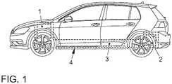
- the Fig. 1 shows a motor vehicle according to the invention.
- This is designed in the form of a hybrid vehicle and accordingly comprises an internal combustion engine 1 accommodated in an engine compartment, which is arranged in the region of the front of the motor vehicle, as part of a vehicle Internal combustion engine, which is provided as needed to provide a traction drive power for the motor vehicle, and an electric traction motor 2, which is also provided as needed to provide a traction drive power for the motor vehicle and this can be supplied from a battery 3 with the required electrical power.
- the internal combustion engine 1, the electric traction motor 2 and the battery 3 are integrated in a cooling system 4 according to the invention, which forms at least one cooling circuit 10.
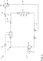
- this (partial) cooling system comprises a for example by means of an electric motor 5 driven coolant pump 6, a heat exchanger 7, which may be, for example, in an electric traction motor 2 integrated or associated cooling channels, and an ambient heat exchanger 8, for example, a main cooler of cooling system.
- the coolant pump 6, the heat exchanger 7 and the ambient heat exchanger 8 are fluidly connected to each other by means of coolant lines 9 and integrated into a cooling circuit 10 such that the heat exchanger 7 are conveyed in the cooling circuit 10 with respect to a defined conveying direction, in the liquid coolant 12 by means of the coolant pump 6 is, is disposed between the coolant pump 6 and the ambient heat exchanger 8.
- the cooling system 4 further comprises a surge tank 11, which, in a horizontal orientation of a motor vehicle comprising the cooling system 4, the highest cavity of the cooling system 4, which is provided for receiving coolant 12, is formed.
- This cavity of the expansion tank 11 is partially filled with the coolant 12 and partially with a gas 13, in particular air, in order to be able to compensate for different expansions of the coolant 12 as a result of temperature changes during operation of the cooling system 4.
- a compensation line 14 leaves the expansion tank 11 from the lower section of the expansion tank 11, preferably at the lowest point of the cavity of the expansion tank 11.
- a first vent line 15 is provided, which goes from that coolant line 9, which connects the heat exchanger 7 directly to the ambient heat exchanger 8, the corresponding branch preferably (in a horizontal orientation of the cooling system 4 comprehensive motor vehicle) at a location as high as possible of Cooling circuit 10 is arranged.
- the first vent line 15 is carried away from the refrigerant flowing in the cooling circuit 10 12 entrained gas 13 from the cooling circuit 10 and transferred to the expansion tank 11 and the cooling circuit 10 are thus total vented.
- the first vent line 15 opens into a / the upper portion of the surge tank 11, in which in the normal case, that is, in a normal operation of the cooling system 4, gas 13 is arranged.
- a check valve in the form of a check valve 16 is further integrated, which is designed and arranged such that it automatically closes at an overpressure on its side connected to the expansion tank 11 side.
- a fluid gas and / or coolant
- the cooling system 4 further comprises a second vent line 17 which branches off at the highest point from an integrated into the cooling circuit 10, provided for guiding the coolant cavity of the heat exchanger 7 and also in that coolant line 9, the ambient heat exchanger 8 with the coolant pump. 6 directly connects, flows.
- the second vent line 17, as shown in the Fig. 2 is shown, also run at least partially sloping. Via this second vent line 17, gas 13, which accumulates due to a functionally required, relatively complex configuration of this cavity of the heat exchanger 7 therein, dissipated and introduced back into the refrigerant circuit 10 flowing through the coolant 12, so that this then via the first vent line 15th can be discharged into the expansion tank 11.
- Such a discharge of gas 13 from the heat exchanger 7 is based on a suction, which is ensured in the operation of the coolant pump 6 by the negative pressure, which prevails on the suction side in comparison to the pressure on the pressure side.
- the heat exchanger 7 is directly, ie without the interposition of a component, by which a flow of the coolant would be influenced to a relevant extent, downstream of the coolant pump 6 (with respect the defined flow direction of the coolant 12) integrated into the cooling circuit 10.
- the ambient heat exchanger 8 with the Coolant pump 6 connects and in which the second vent line 17 opens, arranged immediately and in the shortest possible distance upstream of the coolant pump 6.
- this coolant line 9, which connects the ambient heat exchanger 8 directly to the coolant pump 6, is formed over the entire longitudinal course with a substantially constant flow cross-sectional area.
- a check valve in the form of a check valve 16 is integrated, which is designed and arranged such that it automatically closes at a negative pressure on its side connected to the heat exchanger 7 side. Such a negative pressure can occur in particular when the coolant pump 6 is at a standstill.
- the check valve 16 of the second vent line 17 then prevents overflow of coolant 12 via the second vent line 17 into the heat exchanger 7.
Landscapes
- Engineering & Computer Science (AREA)
- Chemical & Material Sciences (AREA)
- Combustion & Propulsion (AREA)
- Mechanical Engineering (AREA)
- General Engineering & Computer Science (AREA)
- Cooling, Air Intake And Gas Exhaust, And Fuel Tank Arrangements In Propulsion Units (AREA)
- Electric Propulsion And Braking For Vehicles (AREA)
Abstract
Description
- Die Erfindung betrifft ein Kühlsystem für ein Kraftfahrzeug mit einem Kühlkreis, in den eine Kühlmittelpumpe zur Förderung eines flüssigen Kühlmittels in einer definierten Förderrichtung in dem Kühlkreis und ein Wärmetauscher integriert sind, wobei die Kühlmittelpumpe und der Wärmetauscher über Kühlmittelleitungen miteinander verbunden sind und wobei eine erste Entlüftungsleitung aus dem Kühlkreis abzweigt und zu einem Ausgleichsbehälter führt und eine zweite Entlüftungsleitung den Wärmetauscher mit einem Abschnitt einer der Kühlmittelleitungen verbindet. Die Erfindung betrifft weiterhin ein Kraftfahrzeug mit einem solchen Kühlsystem.
- Ein Kraftfahrzeug weist in der Regel mindestens ein Kühlsystem auf, das auf der Zirkulation einer Kühlflüssigkeit in mindestens einem Kühlkreis beruht. Bei der Durchströmung einer oder mehrerer in den Kühlkreis integrierter und zu kühlender Komponenten des Kraftfahrzeugs nimmt das Kühlmittel Wärmeenergie auf, die in einem Umgebungswärmetauscher zumindest teilweise wieder an die Umgebungsluft abgegeben wird. Dadurch kann eine Kühlung der zu kühlenden Komponenten realisiert werden, die besonders einfach und gut an unterschiedliche Kühlleistungsanforderungen der zu kühlenden Komponenten angepasst ist.
- Ein solches Kühlsystem weist in der Regel auch eine oder mehrere Vorrichtungen auf, die eine Entlüftung der in den Kühlkreis integrierten Komponenten beziehungsweise des gesamten Kühlkreises ermöglichen. Eine solche Entlüftung ist insbesondere bei einer erstmaligen oder wartungsbedingten Befüllung des Kühlkreises mit der Kühlflüssigkeit erforderlich. Weiterhin kann auch im Betrieb des Kühlsystems Gas aus der Kühlflüssigkeit austreten, das abgeführt werden sollte, um u.a. eine Verschlechterung des Wärmeübergangs in den wärmetauschenden Komponenten des Kühlsystems und damit der Kühlleistung zu vermeiden.
- Ein Kühlsystem der eingangs genannten Art ist aus der
DE 10 2012 006 518 A1 bekannt. Bei dem dortigen Kühlsystem ist derjenige Abschnitt, in den die von dem Wärmetauscher kommende zweite Entlüftungsleitung mündet, in Form einer Venturidüse ausgebildet. Dadurch soll ausgenutzt werden, dass bei der Strömung der Kühlflüssigkeit durch den Bereich der Venturidüse, der eine verringerte Strömungsquerschnittsfläche aufweist, ein Unterdruck erzeugt wird, der dazu ausgenutzt werden kann, über die seitlich in diesen Bereich der Venturidüse mündende zweite Entlüftungsleitung ein Fluid, d.h. ein Gas, sofern ein solches im Bereich der Abzweigung der zweiten Entlüftungsleitung aus dem Wärmetauscher vorliegt, ansonsten Kühlflüssigkeit, abzusaugen. - Die
DE 10 2011 118 837 A1 beschreibt einen Kühlkreis einer Brennkraftmaschine mit einem Ausgleichsbehälter und einem Wärmetauscher. Durch eine Zuführleitung gelangt Kühlmittel in den Wärmetauscher. In einem oberen Bereich des Wärmetauschers befindet sich eine Austrittsöffnung für das Kühlmittel. An die Austrittsöffnung schließt sich eine Verzweigung an, durch die einerseits ein Hauptvolumenstrom einem Niedertemperaturbereich zugeführt wird und durch die andererseits ein Nebenvolumenstrom durch eine Entlüftungsleitung in den Ausgleichsbehälter zurückgeführt wird. Aufgrund einer hohen Strömungsgeschwindigkeit in der Entlüftungsleitung soll die in dem Wärmetauscher vorhandene Luft dem tiefer liegend positionierten Ausgleichsbehälter zugeführt werden können. Die Entlüftungsleitung mündet innerhalb des Ausgleichsbehälters in einen vertikal ausgerichteten, hohlzylindrischen Rohrabschnitt, der somit zumindest abschnittsweise unterhalb des Füllstands des Kühlmittels in dem Ausgleichsbehälter angeordnet ist. In derDE 10 2011 118 837 A1 ist auch offenbart, dass die Strömungsquerschnittsfläche der Entlüftungsleitung wesentlich kleiner als diejenige der Zuführleitung sein und beispielsweise einen Innendurchmesser von 3 mm bis 8 mm und vorzugsweise von 6 mm aufweisen soll. - Die
WO 2008/084099 A2 offenbart eine Anordnung für einen Kühlkreislauf mit einer Entlüftung. Die Anordnung umfasst dabei einen ersten Kreislaufabschnitt des Flüssigkeitskreislaufs, einen zweiten Kreislaufabschnitt des Flüssigkeitskreislaufs und eine Entlüftungseinrichtung zum Entlüften des ersten Kreislaufabschnitts. Der zweite Kreislaufabschnitt ist in Fließrichtung nach dem ersten Kreislaufabschnitt und vor der Entlüftung angeordnet. Die Entlüftungseinrichtung mündet zum Entlüften des ersten Kreislaufabschnitts in einem ersten Anschlussbereich in den ersten Kreislaufabschnitt und in einem zweiten Anschlussbereich in den zweiten Kreislaufabschnitt. Der zweite Kreislaufabschnitt und/oder die Entlüftungseinrichtung in dem zweiten Anschlussbereich sollen derart ausgebildet und/oder angeordnet sein, dass in der Entlüftungseinrichtung eine zum zumindest teilweisen Entlüften des ersten Kreislaufabschnitts ausreichende Sogwirkung in der Entlüftungseinrichtung entsteht. Dies kann unter anderem durch die Anordnung des zweiten Anschlussbereichs im Bereich einer Verengung des Strömungsquerschnitts des zweiten Kreislaufabschnitts und folglich durch den so erzielten Venturi-Effekt erreicht werden. - Nachteilig an einem Absaugen von Gas aus einem zu entlüftenden Wärmetauscher eines Kühlsystems durch die Erzeugung eines Unterdrucks mittels einer Venturidüse, wie dies aus der
DE 10 2012 006 518 A1 oder derWO 2008/084099 A2 bekannt ist, liegt in nicht unerheblichen Strömungsverlusten, die bei der Strömung der Kühlflüssigkeit durch die Venturidüse entstehen. - Der Erfindung lag die Aufgabe zugrunde, ein hinsichtlich dieses Nachteils verbessertes Kühlsystem für ein Kraftfahrzeug anzugeben.
- Diese Aufgabe wird mittels eines Kühlsystems gemäß dem Patentanspruch 1 gelöst. Ein Kraftfahrzeug mit einem solchen Kühlsystem ist Gegenstand des Patentanspruchs 6. Vorteilhafte Ausgestaltungsformen des erfindungsgemäßen Kühlsystems und des erfindungsgemäßen Kraftfahrzeugs sind Gegenstände der weiteren Patentansprüche und/oder ergeben sich aus der nachfolgenden Beschreibung der Erfindung.
- Der Erfindung liegt der Gedanke zugrunde, dass, ausgehend von einem Kühlsystem, wie es grundsätzlich aus der
DE 10 2012 006 518 A1 bekannt ist, bei einer geeigneten Auswahl desjenigen Abschnitts einer Kühlmittelleitung, in den die von dem Wärmetauscher kommende zweite Entlüftungsleitung mündet, auf die Ausgestaltung dieses Abschnitts als Venturidüse verzichtet werden und dennoch ein ausreichendes Druckgefälle über dieser Entlüftungsleitung realisiert werden kann, um eine wirksame Entlüftung des Wärmetauschers zu gewährleisten. Dies gilt konkret, wenn dieser Abschnitt der Kühlmittelleitung auf der Saugseite der oder einer in den Kühlkreis integrierten Kühlmittelpumpe und dabei insbesondere möglichst nah an dieser angeordnet ist, um die dortige Sogwirkung auch für die Entlüftung des Wärmetauschers über die zweite Entlüftungsleitung auszunutzen. - Dementsprechend ist erfindungsgemäß ein Kühlsystem für ein Kraftfahrzeug vorgesehen, das zumindest einen Kühlkreis umfasst, in den zumindest eine Kühlmittelpumpe zur Förderung eines flüssigen Kühlmittels in einer definierten Förderrichtung in dem Kühlkreis und ein Wärmetauscher integriert sind, wobei die Kühlmittelpumpe und der Wärmetauscher direkt und/oder indirekt, d.h. mit oder ohne Zwischenschaltung einer wärmetauschenden Funktionskomponente, über Kühlmittelleitungen zur Ausbildung des Kühlkreises miteinander verbunden sind und wobei eine erste Entlüftungsleitung aus dem Kühlkreis abzweigt und zu einem Ausgleichsbehälter des Kühlsystems führt und eine zweite Entlüftungsleitung den Wärmetauscher mit einem Abschnitt einer der Kühlmittelleitungen verbindet. Weiterhin ist vorgesehen, dass dieser Abschnitt dieser Kühlmittelleitung, in den die zweite Entlüftungsleitung mündet, stromauf der Kühlmittelpumpe bezüglich der definierten Förderrichtung angeordnet ist und eine konstante Strömungsquerschnittsfläche aufweist. Die Strömungsquerschnittsfläche in dem die Mündungsöffnung der zweiten Entlüftungsleitung ausbildenden Bereich ist demnach im Wesentlichen oder vorzugsweise exakt genau so groß wie die Strömungsquerschnittsflächen in den sich an diesen Bereich beidseitig anschließenden Bereichen dieses Abschnitts der Kühlmittelleitung. Folglich soll dieser Abschnitt, in den die zweite Entlüftungsleitung mündet, nicht als Venturidüse ausgebildet sein, so dass Strömungsverluste, die sich bei der Strömung des Kühlmittels durch eine solche Venturidüse infolge einer für eine Venturidüse charakteristischen Querschnittsverengung einstellen würden, vermieden werden können.
- Ein erfindungsgemäßes Kraftfahrzeug ist dadurch gekennzeichnet, dass dieses ein erfindungsgemäßes Kühlsystem umfasst.
- Als Wärmetauscher eines erfindungsgemäßen Kühlsystems können grundsätzlich sämtliche wärmetauschenden Funktionskomponenten (d.h. Komponenten, die bestimmungsgemäß für einen Wärmetausch vorgesehen sind), die üblicherweise, je nach Bedarf, in ein Kühlsystem eines Kraftfahrzeugs integriert sein können, zum Einsatz kommen. Dies sind einerseits Umgebungswärmetauscher eines solchen Kühlsystems, die ausschließlich oder primär einer Übertragung von Wärmeenergie von dem Kühlmittel auf diesen Wärmetauscher ebenfalls durchströmende (Umgebungs-)Luft dienen, d.h. insbesondere
- ein Hauptkühler, in dem zumindest temporär ein primäres Rückkühlen des durch die Aufnahme von Wärmeenergie bei der Durchströmung von zu kühlenden Komponenten des Kraftfahrzeugs erwärmten Kühlmittels erfolgt,
- ein Nebenkühler, der insbesondere bei einer Aufteilung des Kühlsystems in einerseits zumindest einen Hochtemperaturkühlkreis und zumindest einen Niedertemperaturkühlkreis unterstützend zu dem dann in den Hochtemperaturkühlkreis integrierten Hauptkühler mit der Funktion einer Rückkühlung des Kühlmittels vorgesehen ist, wobei der Nebenkühler dann insbesondere in den Niedertemperaturkühlkreis integriert sein kann,
- ein Ladeluftkühler zur Kühlung des infolge einer Verdichtung mittels beispielsweise eines Verdichters eines Abgasturboladers erwärmten Frischgases, das über einen Frischgasstrang einem Verbrennungsmotor des Kraftfahrzeugs zugeführt wird, sowie
- ein Heizungswärmetauscher, der zur bedarfsweisen Erwärmung von einem Fahrgastraum des Kraftfahrzeugs zuzuführender Luft vorgesehen ist.
- Weiterhin kann der mindestens eine Wärmetauscher eines erfindungsgemäßen Kühlsystems als Kühler ausgebildet sein, der ausschließlich oder primär einer Übertragung von Wärmeenergie von einem Komponentenkörper oder einem anderen Medium auf das Kühlmittel dienen kann. Dies sind insbesondere
- ein Kühlkanal oder mehrere Kühlkanäle in einem Gehäuse (Zylinderkopf- und/oder Zylindergehäuse) eines Verbrennungsmotors einer Brennkraftmaschine des Kraftfahrzeugs,
- ein Motorölkühler zur bedarfsweise Kühlung von Schmiermittel, das zumindest auch zur Schmierung eines solchen Verbrennungsmotors vorgesehen ist,
- ein Getriebeölkühler zur bedarfsweise Kühlung eines Schaltgetriebes des Kraftfahrzeugs und insbesondere von Getriebeöl des Schaltgetriebes,
- ein Kühlkanal oder mehrere Kühlkanäle in einem Gehäuse eines Abgasturboladers einer Brennkraftmaschine des Kraftfahrzeugs sowie
- ein Kühlkanal oder mehrere Kühlkanäle eines elektrischen Traktionsmotors und/oder einer zur Ansteuerung eines solchen elektrischen Traktionsmotors vorgesehenen Leistungselektronik und/oder einer zur Versorgung eines solchen elektrischen Traktionsmotors mit elektrischer Leistung vorgesehenen Batterie des Kraftfahrzeugs bei dessen Ausgestaltung als Elektro- oder Hybridfahrzeug.
- Als "Ausgleichsbehälter" wird erfindungsgemäß ein Reservoir für das Kühlmittel des Kühlsystems verstanden, das dazu dient, insbesondere temperaturbedingte Ausdehnungen des Kühlmittels durch eine Veränderung des Füllstands des Kühlmittels in dem Ausgleichsbehälter auszugleichen. Dazu kann ein solcher Ausgleichsbehälter insbesondere teilweise mit dem Kühlmittel und teilweise mit einem Gas, insbesondere Luft, gefüllt sein. Die erste Entlüftungsleitung kann vorzugsweise in einen Abschnitt des Ausgleichsbehälters münden, indem das Gas vorhanden ist. Andererseits kann eine Ausgleichsleitung vorgesehen sein, mittels der der Ausgleichsbehälter, insbesondere in einem das Kühlmittel aufnehmenden Abschnitt, zusätzlich mit dem Kühlkreis verbunden ist, um ein Überströmen von Kühlmittel zwischen dem Kühlkreis und dem Ausgleichsbehälter mit dem primären Ziel der Kompensation einer temperaturbedingten Ausdehnung des Kühlmittels, gegebenenfalls auch für ein erstmaliges oder im Rahmen von Wartungstätigkeiten vorgesehenes Befüllen des Kühlsystems oder zumindest des Kühlkreises mit dem Kühlmittel, zu ermöglichen.
- Gemäß einer bevorzugten Ausgestaltungsform eines erfindungsgemäßen Kühlsystems kann vorgesehen sein, dass der Abschnitt, in den die zweite Entlüftungsleitung mündet, unmittelbar stromauf der Kühlmittelpumpe bezüglich der definierten Förderrichtung angeordnet ist. Demnach soll zwischen diesem Abschnitt und der Kühlmittelpumpe keine Komponente des Kühlkreises vorhanden sein, durch die eine Strömung des Kühlmittels im relevanten Maße beeinflusst wird, wie dies insbesondere bei einer dortigen Integration eines Wärmetauschers, einer Verzweigung der Kühlmittelleitung, eines Ventils oder einer sonstigen Drossel der Fall wäre. Vorzugsweise ist vorgesehen, dass zwischen diesem Abschnitt der Kühlmittelleitung, in den die zweite Entlüftungsleitung mündet, und der Kühlmittelpumpe ausschließlich ein verzweigungsfreier Abschnitt der Kühlmittelleitung angeordnet ist. Weiterhin bevorzugt kann dieser Abschnitt möglichst kurz ausgebildet und/oder mit einer (über dem Längsverlauf) konstanten Strömungsquerschnittsfläche ausgebildet sein. Durch eine solche Ausgestaltung eines erfindungsgemäßen Kühlsystems kann der im Betrieb der Kühlmittelpumpe durch diese bewirkte Unterdruck auf ihrer Saugseite im besonderen Maße zum Absaugen eines Fluids und insbesondere eines Gases, sofern vorhanden, aus dem Wärmetauscher bewirkt werden.
- Gemäß einer weiterhin bevorzugten Ausgestaltungsform eines erfindungsgemäßen Kühlsystems kann vorgesehen sein, dass die zweite Entlüftungsleitung eine vorzugsweise über ihrem Längsverlauf konstante Strömungsquerschnittsfläche von zwischen 0,2 mm2 und 20 mm2, vorzugsweise von zwischen 2 mm2 und 5 mm2 und besonders bevorzugt von zwischen 3 mm2 und 3,3 mm2 aufweist. Bei einer weiterhin bevorzugten Ausgestaltung der zweiten Entlüftungsleitung mit kreisförmiger Strömungsquerschnittsfläche entsprechenden diese Werte ungefähr einem bevorzugten Durchmesser von zwischen 0,5 mm und 5 mm, vorzugsweise von 1,5 mm und 2,5 mm und besonders bevorzugt von ungefähr 2 mm. Sofern die zweite Entlüftungsleitung keine über dem Längsverlauf konstante Strömungsquerschnittsfläche aufweist, sollen sich diese Werte auf entweder die kleinste oder die über dem Längsverlauf gemittelte Strömungsquerschnittsfläche beziehen. Eine solche relativ kleine Dimensionierung der zweiten Entlüftungsleitung, die deutlich unter der üblichen Dimensionierung für eine Entlüftungsleitung bei einem konventionellen Kühlsystems liegt, ermöglicht in ausreichendem Maße ein Absaugen von im Bereich der Abzweigung in dem Wärmetauscher angesammeltem Gas aufgrund des mittels der Kühlmittelpumpe im Bereich der Mündung der zweiten Entlüftungsleitung in die Kühlmittelleitung erzeugten Unterdrucks. Gleichzeitig wird dadurch der Mengenstrom an Kühlmittel, der infolge dieses Unterdrucks über die Entlüftungsleitung aus dem Wärmetauscher abgeführt wird, sofern kein oder nur eine geringe Menge Gas im Bereich dieser Abzweigung vorhanden ist, gering gehalten, was sich vorteilhaft auf den Betrieb und insbesondere eine Heiz- und/oder Kühlfunktionalität des Wärmetauschers auswirken kann. Ist der Wärmetauscher nämlich als Umgebungswärmetauscher ausgebildet, der ausschließlich oder primär einer Übertragung von Wärmeenergie von dem Kühlmittel auf Luft dient, wird durch ein solches Absaugen von Kühlmittel aus dem Wärmetauscher gegebenenfalls die Heizleistung des Wärmetauschers reduziert. Ist der Wärmetauscher dagegen als Kühler ausgebildet, der ausschließlich oder primär einer Übertragung von Wärmeenergie von einem Komponentenkörper oder einem anderen Medium auf das Kühlmittel dient, wird durch ein solches Absaugen von Kühlmittel aus dem Wärmetauscher gegebenenfalls die Kühlleistung des Wärmetauschers reduziert. Durch eine Minimierung eines gegebenenfalls über die zweite Entlüftungsleitung aus dem Wärmetauscher abgeführten Kühlmittelmengenstroms kann folglich auch eine damit verbundene Verschlechterung einer Heiz- oder Kühlfunktionalität gering gehalten werden.
- Vorzugsweise kann vorgesehen sein, dass in die zweite Entlüftungsleitung ein Absperrventil, das vorzugsweise in Form eines Rückschlagventils ausgebildet sein kann, integriert ist. Dieses Absperrventil ist dabei derart ausgebildet, dass dieses bei einem Unterdruck auf seiner mit dem Wärmetauscher verbundenen Seite schließt. Anstelle einer Verwendung eines selbsttätigen Rückschlagventils ist auch die Nutzung eines aktiv ansteuerbaren Absperrventils möglich. Durch ein solches Absperrventil kann in vorteilhafter Weise vermieden werden, dass bei einer nicht betriebenen Kühlmittelpumpe infolge eines dann im Bereich der Mündung der zweiten Entlüftungsleitung in die Kühlmittelleitung gegebenenfalls anliegenden Überdrucks im Vergleich zu dem Druck im Bereich der Abzweigung aus dem Wärmetauscher Kühlmittel über die zweite Entlüftungsleitung in den Wärmetauscher überströmt.
- Gemäß einer bevorzugten Ausgestaltung eines erfindungsgemäßen Kraftfahrzeugs kann vorgesehen sein, dass die zweite Entlüftungsleitung bei waagerechter Ausrichtung des Kraftfahrzeugs an der am höchsten gelegenen Stelle aus einem in den Kühlkreis integrierten Hohlraum des Wärmetauschers abzweigt. Dadurch kann ein möglichst vollständiges Abführen von sich in dem Wärmetauscher ansammelndem Gas mittels der zweiten Entlüftungsleitung erreicht werden.
- Weiterhin bevorzugt kann vorgesehen sein, dass der Ausgleichsbehälter bei waagerechter Ausrichtung des Kraftfahrzeugs den am höchsten gelegenen Hohlraum des Kühlsystems, der zur Aufnahme von Kühlmittel vorgesehen ist, ausbildet, wodurch in vorteilhafter Weise eine Entlüftung des Kühlkreises über die erste Entlüftungsleitung und den Ausgleichsbehälter erfolgen kann.
- Da eine Entlüftung des Wärmetauschers über die zweite Entlüftungsleitung auf einem Absaugen von sich in dem Wärmetauscher ansammelndem Gas infolge eines ausreichenden Druckgefälles über der zweiten Entlüftungsleitung basiert, ist es nicht erforderlich, die zweite Entlüftungsleitung zur Sicherstellung eines problemlosen Abführens des Gases kontinuierlich ansteigend verlaufend auszubilden. Folglich kann bei einem erfindungsgemäßen Kraftfahrzeug in vorteilhafter Weise auch vorgesehen sein, dass die zweite Entlüftungsleitung bei waagerechter Ausrichtung des Kraftfahrzeugs zumindest teilweise abfallend verlaufend ausgebildet ist, wodurch die Integration des Kühlsystems und insbesondere der Entlüftungsleitung in das Kraftfahrzeug gegebenenfalls deutlich vereinfacht werden kann.
- Dies kann beispielsweise ein besonderer Vorteil bei einem erfindungsgemäßen Kraftfahrzeug sein, das einen elektrischen Traktionsmotor aufweist, der vorzugsweise mittels des Kühlsystems gekühlt wird, da bei einem solchen Kraftfahrzeug in vorteilhafter Weise vorgesehen sein kann, den elektrischen Traktionsmotor im Bereich des Hecks des Kraftfahrzeugs anzuordnen (insbesondere um eine Hinterachse des Kraftfahrzeugs durch diesen antreiben zu lassen), während der Großteil der Komponenten des Kühlsystems sowie der weiteren, durch dieses Kühlsystem zu kühlenden Komponenten im Bereich einer Front des Kraftfahrzeugs angeordnet sind. Sofern es sich bei dem oder zumindest bei einem der Wärmetauscher des Kühlsystems um Kühlkanäle für einen solchen elektrischen Traktionsmotor handelt, kann dann noch vorgesehen sein, dass die/eine zweite Entlüftungsleitung von dem elektrischen Traktionsmotor im Heck des Kraftfahrzeugs bis zu einem im Bereich der Front des Kraftfahrzeugs angeordneten Abschnitt derjenigen Kühlmittelleitung, in den die zweite Entlüftungsleitung mündet, geführt werden muss, was bedingen kann, die zweite Entlüftungsleitung teilweise abfallend auszubildenden, beispielsweise, um diese entlang des Unterbodens des Kraftfahrzeugs zu führen.
- Die unbestimmten Artikel ("ein", "eine", "einer" und "eines"), insbesondere in den Patentansprüchen und in der die Patentansprüche allgemein erläuternden Beschreibung, sind als solche und nicht als Zahlwörter zu verstehen. Entsprechend damit konkretisierte Komponenten sind somit so zu verstehen, dass diese mindestens einmal vorhanden sind und mehrfach vorhanden sein können.
- Die vorliegende Erfindung wird nachfolgend anhand von in den Zeichnungen dargestellten Ausführungsbeispielen näher erläutert. In den Zeichnungen zeigt, jeweils in vereinfachter Darstellung:
- Fig. 1:
- ein erfindungsgemäßes Kraftfahrzeug und
- Fig. 2:
- ein erfindungsgemäßes Kühlsystem.
- Die
Fig. 1 zeigt ein erfindungsgemäßes Kraftfahrzeug. Dieses ist in Form eines Hybridfahrzeugs ausgebildet und umfasst demnach eine in einem Motorraum, der im Bereich der Front des Kraftfahrzeugs angeordnet ist, aufgenommenen Verbrennungsmotor 1 als Teil einer Brennkraftmaschine, die bedarfsweise zur Bereitstellung einer Fahrantriebsleistung für das Kraftfahrzeug vorgesehen ist, sowie einen elektrischen Traktionsmotor 2, der ebenfalls bedarfsweise zur Bereitstellung einer Fahrantriebsleistung für das Kraftfahrzeug vorgesehen ist und hierzu aus einer Batterie 3 mit der dafür erforderlichen elektrischen Leistung versorgt werden kann. Der Verbrennungsmotor 1, der elektrische Traktionsmotor 2 und die Batterie 3 sind in ein erfindungsgemäßes Kühlsystem 4 integriert, das mindestens einen Kühlkreis 10 ausbildet. - Ein solches Kühlsystem 4 oder zumindest ein Teil (mit einem Kühlkreis) davon ist gemäß einer beispielhaften Ausgestaltungsform in der
Fig. 2 dargestellt. Demnach umfasst dieses (Teil-)Kühlsystem eine beispielsweise mittels eines Elektromotors 5 antreibbare Kühlmittelpumpe 6, einen Wärmetauscher 7, bei dem es sich beispielsweise um in einen elektrischen Traktionsmotor 2 integrierte oder diesem zugeordnete Kühlkanäle handeln kann, sowie einen Umgebungswärmetauscher 8, beispielsweise einen Hauptkühler des Kühlsystems. Die Kühlmittelpumpe 6, der Wärmetauscher 7 und der Umgebungswärmetauscher 8 sind mittels Kühlmittelleitungen 9 fluidleitend miteinander verbunden und derart in einen Kühlkreis 10 integriert, dass der Wärmetauscher 7 bezüglich einer definierten Förderrichtung, in der flüssiges Kühlmittel 12 mittels der Kühlmittelpumpe 6 in dem Kühlkreis 10 gefördert werden soll, zwischen der Kühlmittelpumpe 6 und dem Umgebungswärmetauscher 8 angeordnet ist. - Das Kühlsystem 4 gemäß der
Fig. 2 umfasst weiterhin einen Ausgleichsbehälter 11, der, bei einer waagerechten Ausrichtung eines das Kühlsystem 4 umfassenden Kraftfahrzeugs, den am höchsten gelegenen Hohlraum des Kühlsystems4, der zur Aufnahme von Kühlmittel 12 vorgesehen ist, ausbildet. Dieser Hohlraum des Ausgleichsbehälters 11 ist teilweise mit dem Kühlmittel 12 und teilweise mit einem Gas 13, insbesondere Luft, gefüllt, um im Betrieb des Kühlsystems 4 unterschiedliche Ausdehnungen des Kühlmittels 12 infolge von Temperaturänderungen ausgleichen zu können. Dazu sowie um zu ermöglichen, das Kühlsystem 4 erstmalig sowie zu Wartungszwecken mit Kühlmittel 12 zu befüllen, geht aus dem unteren Abschnitt des Ausgleichsbehälters 11, vorzugsweise an der am tiefsten gelegenen Stelle des Hohlraums des Ausgleichsbehälters 11, eine Ausgleichsleitung 14 aus dem Ausgleichsbehälter 11 ab, die in diejenige Kühlmittelleitung 9, die den Umgebungswärmetauscher 8 direkt mit der Kühlmittelpumpe 6 verbindet, mündet. Weiterhin ist eine erste Entlüftungsleitung 15 vorgesehen, die aus derjenigen Kühlmittelleitung 9, die den Wärmetauscher 7 direkt mit dem Umgebungswärmetauscher 8 verbindet, abgeht, wobei der entsprechende Abzweig vorzugsweise (bei einer waagerechten Ausrichtung eines das Kühlsystem 4 umfassenden Kraftfahrzeugs) an einer möglichst hoch gelegenen Stelle des Kühlkreises 10 angeordnet ist. Über diese erste Entlüftungsleitung 15 soll von dem in dem Kühlkreis 10 strömenden Kühlmittel 12 mitgeführtes Gas 13 aus dem Kühlkreis 10 abgeführt und in den Ausgleichsbehälter 11 überführt und der Kühlkreis 10 insgesamt somit entlüftet werden. Die erste Entlüftungsleitung 15 mündet dafür in einen/den oberen Abschnitt des Ausgleichsbehälters 11, in dem im Normalfall, d.h. in einem Normalbetrieb des Kühlsystems 4, Gas 13 angeordnet ist. - In die erste Entlüftungsleitung15 ist weiterhin ein Absperrventil in Form eines Rückschlagventils 16 integriert, das derart ausgebildet und angeordnet ist, dass dieses bei einem Überdruck auf seiner mit dem Ausgleichsbehälter 11 verbundenen Seite selbsttätig schließt. Durch dieses Rückschlagventil 16 kann ein Überströmen eines Fluids (Gas und/oder Kühlmittel) aus dem Ausgleichsbehälter 11 über die erste Entlüftungsleitung 15 in den Kühlkreis 10 bei einem entsprechenden Druckgefälle vermieden werden.
- Das Kühlsystem 4 umfasst weiterhin eine zweite Entlüftungsleitung 17, die an der am höchsten gelegenen Stelle aus einem in den Kühlkreis 10 integrierten, zur Führung des Kühlmittels vorgesehenen Hohlraum des Wärmetauschers 7 abzweigt und ebenfalls in diejenige Kühlmittelleitung 9, die den Umgebungswärmetauscher 8 mit der Kühlmittelpumpe 6 direkt verbindet, mündet. Dabei kann die zweite Entlüftungsleitung 17, wie dies in der
Fig. 2 dargestellt ist, auch zumindest teilweise abfallend verlaufen. Über diese zweite Entlüftungsleitung 17 kann Gas 13, das sich aufgrund einer funktional erforderlichen, relativ komplexen Ausgestaltung dieses Hohlraums des Wärmetauschers 7 darin ansammelt, abgeführt und wieder in das den Kühlkreis 10 durchströmende Kühlmittel 12 eingeleitet werden, so dass dieses dann über die erste Entlüftungsleitung 15 in den Ausgleichsbehälter 11 abgeführt werden kann. - Ein solches Abführen von Gas 13 aus dem Wärmetauscher 7 basiert auf einem Absaugen, das im Betrieb der Kühlmittelpumpe 6 durch den Unterdruck, der auf deren Saugseite im Vergleich zu dem Druck auf der Druckseite herrscht, sichergestellt ist. Um dieses auch über der zweiten Entlüftungsleitung 17 anliegende Druckgefälle für eine Entlüftung des Wärmetauschers 7 möglichst optimal auszunutzen, ist der Wärmetauscher 7 unmittelbar, d.h. ohne Zwischenschaltung einer Komponente, durch die eine Strömung des Kühlmittels im relevanten Maße beeinflusst würde, stromab der Kühlmittelpumpe 6 (bezüglich der definierten Strömungsrichtung des Kühlmittels 12) in den Kühlkreis 10 integriert. Gleichzeitig ist derjenige Abschnitt der Kühlmittelleitung 9, der den Umgebungswärmetauscher 8 mit der Kühlmittelpumpe 6 verbindet und in den die zweite Entlüftungsleitung 17 mündet, unmittelbar sowie in möglichst kurzer Entfernung stromauf der Kühlmittelpumpe 6 angeordnet.
- Da das im Betrieb der Kühlmittelpumpe 6 mittels dieser erzeugte Druckgefälle über der zweiten Entlüftungsleitung 17 für eine Entlüftung des Wärmetauschers7 ausreichend ist, ist der Abschnitt der Kühlmittelleitung 9, in den die zweite Entlüftungsleitung 17 mündet, ohne besondere konstruktive Maßnahmen zur Erzeugung eines Unterdrucks in dem diesen durchströmenden Kühlmittel 12 und insbesondere auch nicht in Form einer Venturidüse ausgebildet. Vielmehr kann vorgesehen sein, dass diese Kühlmittelleitung 9, die den Umgebungswärmetauscher 8 mit der Kühlmittelpumpe 6 direkt verbindet, über den gesamten Längsverlauf mit einer im Wesentlichen konstant großen Strömungsquerschnittsfläche ausgebildet ist.
- Auch in die zweite Entlüftungsleitung 17 ist ein Absperrventil in Form eines Rückschlagventils 16 integriert, das derart ausgebildet und angeordnet ist, dass dieses bei einem Unterdruck auf seiner mit dem Wärmetauscher 7 verbundenen Seite selbsttätig schließt. Ein solcher Unterdruck kann insbesondere im Stillstand der Kühlmittelpumpe 6 auftreten. Das Rückschlagventil 16 der zweiten Entlüftungsleitung 17 verhindert dann ein Überströmen von Kühlmittel 12 über die zweite Entlüftungsleitung 17 in den Wärmetauscher 7.
-
- 1.
- Verbrennungsmotor
- 2.
- elektrischer Traktionsmotor
- 3.
- Batterie
- 4.
- Kühlsystem
- 5.
- Elektromotor
- 6.
- Kühlmittelpumpe
- 7.
- Wärmetauscher
- 8.
- Umgebungswärmetauscher
- 9.
- Kühlmittelleitung
- 10.
- Kühlkreis
- 11.
- Ausgleichsbehälter
- 12.
- Kühlmittel
- 13.
- Gas
- 14.
- Ausgleichsleitung
- 15.
- erste Entlüftungsleitung
- 16.
- Rückschlagventil
- 17.
- zweite Entlüftungsleitung
Claims (10)
- Kühlsystem (4) für ein Kraftfahrzeug mit einem Kühlkreis (10), in den eine Kühlmittelpumpe (6) zur Förderung eines flüssigen Kühlmittels (12) in einer definierten Förderrichtung in dem Kühlkreis (10) und ein Wärmetauscher (7) integriert sind, wobei die Kühlmittelpumpe (6) und der Wärmetauscher (7) über Kühlmittelleitungen (9) zur Ausbildung des Kühlkreises (10) miteinander verbunden sind und wobei eine erste Entlüftungsleitung (15) aus dem Kühlkreis (10) abzweigt und zu einem Ausgleichsbehälter (14) führt und eine zweite Entlüftungsleitung (17) den Wärmetauscher (7) mit einem Abschnitt einer der Kühlmittelleitungen (9) verbindet, dadurch gekennzeichnet, dass dieser Abschnitt dieser Kühlmittelleitung (9) stromauf der Kühlmittelpumpe (6) angeordnet ist und eine konstante Strömungsquerschnittsfläche aufweist.
- Kühlsystem (4) gemäß Anspruch 1, dadurch gekennzeichnet, dass der Abschnitt, in den die zweite Entlüftungsleitung (17) mündet, unmittelbar stromauf der Kühlmittelpumpe (6) angeordnet ist.
- Kühlsystem (4) gemäß Anspruch 1 oder 2, dadurch gekennzeichnet, dass die zweite Entlüftungsleitung (17) eine Strömungsquerschnittsfläche von zwischen 0,2 mm2 und 20 mm2 oder von zwischen 2 mm2 und 5 mm2 oder von zwischen 3 mm2 und 3,3 mm2 aufweist.
- Kühlsystem (4) gemäß einem der vorhergehenden Ansprüche, dadurch gekennzeichnet, dass in die zweite Entlüftungsleitung (17) ein Absperrventil integriert ist, das derart ausgebildet ist, dass dieses bei einem Unterdruck auf seiner mit dem Wärmetauscher (7) verbundenen Seite schließt.
- Kühlsystem (4) gemäß Anspruch 4, dadurch gekennzeichnet, dass das Absperrventil als Rückschlagventil (16) ausgebildet ist.
- Kraftfahrzeug mit einem Kühlsystem (4) gemäß einem der vorhergehenden Ansprüche.
- Kraftfahrzeug gemäß Anspruch 6, dadurch gekennzeichnet, dass die zweite Entlüftungsleitung (17) bei waagerechter Ausrichtung des Kraftfahrzeugs an der am höchsten gelegenen Stelle aus einem in den Kühlkreis (10) integrierten Hohlraum des Wärmetauschers (7) abzweigt.
- Kraftfahrzeug gemäß Anspruch 6 oder 7, dadurch gekennzeichnet, dass der Ausgleichsbehälter (11) bei waagerechter Ausrichtung des Kraftfahrzeugs den am höchsten gelegenen Hohlraum des Kühlsystems (4) zur Aufnahme des Kühlmittels (12) ausbildet.
- Kraftfahrzeug gemäß einem der Ansprüche 6 bis 8, dadurch gekennzeichnet, dass die zweite Entlüftungsleitung (17) bei waagerechter Ausrichtung des Kraftfahrzeugs zumindest teilweise abfallend verlaufend ausgebildet ist.
- Kraftfahrzeug gemäß einem der Ansprüche 6 bis 9, gekennzeichnet durch einen elektrischen Traktionsmotor (2).
Applications Claiming Priority (1)
| Application Number | Priority Date | Filing Date | Title |
|---|---|---|---|
| DE102017116600.9A DE102017116600A1 (de) | 2017-07-24 | 2017-07-24 | Kühlsystem und Kraftfahrzeug |
Publications (2)
| Publication Number | Publication Date |
|---|---|
| EP3434873A1 true EP3434873A1 (de) | 2019-01-30 |
| EP3434873B1 EP3434873B1 (de) | 2021-11-10 |
Family
ID=62909417
Family Applications (1)
| Application Number | Title | Priority Date | Filing Date |
|---|---|---|---|
| EP18182606.6A Active EP3434873B1 (de) | 2017-07-24 | 2018-07-10 | Kühlsystem und kraftfahrzeug |
Country Status (3)
| Country | Link |
|---|---|
| EP (1) | EP3434873B1 (de) |
| CN (1) | CN109296444B (de) |
| DE (1) | DE102017116600A1 (de) |
Families Citing this family (5)
| Publication number | Priority date | Publication date | Assignee | Title |
|---|---|---|---|---|
| DE102019210967A1 (de) * | 2019-07-24 | 2021-01-28 | Volkswagen Aktiengesellschaft | Kühlkreislauf |
| DE102019130429A1 (de) * | 2019-11-12 | 2021-05-12 | Dr. Ing. H.C. F. Porsche Aktiengesellschaft | Kühlkreislaufanordnung |
| DE102020206674A1 (de) * | 2020-05-28 | 2021-12-02 | Volkswagen Aktiengesellschaft | Hybridfahrzeug mit einem Kühlsystem |
| DE102021110014B4 (de) * | 2021-04-20 | 2025-05-08 | Röchling Automotive SE | Kühlflüssigkeit-Ausgleichsbehälter mit integrierter, von der Behälterwand längs ihres gesamten Umfangs beabstandeter Wirbelkammer |
| DE102022121619A1 (de) * | 2022-08-26 | 2024-03-14 | Dr. Ing. H.C. F. Porsche Aktiengesellschaft | Verfahren zum Entlüften eines Fluidkreislaufs |
Citations (5)
| Publication number | Priority date | Publication date | Assignee | Title |
|---|---|---|---|---|
| US2841127A (en) * | 1955-02-16 | 1958-07-01 | White Motor Co | Cooling system |
| EP0157167A1 (de) * | 1982-07-15 | 1985-10-09 | Bayerische Motoren Werke Aktiengesellschaft, Patentabteilung AJ-3 | Kühlkreis für Brennkraftmaschinen |
| WO2008010749A1 (en) * | 2006-07-20 | 2008-01-24 | Volvo Lastvagnar Ab | Cooling system |
| WO2008084099A2 (de) * | 2007-01-11 | 2008-07-17 | Bombardier Transportation Gmbh | Entlüftung für einen flüssigkeitskreislauf |
| DE102012006518A1 (de) * | 2012-03-29 | 2013-03-07 | Audi Ag | Kühlmittelkreislauf eines Fahrzeugs |
Family Cites Families (9)
| Publication number | Priority date | Publication date | Assignee | Title |
|---|---|---|---|---|
| DE3226509A1 (de) * | 1982-07-15 | 1984-01-26 | Bayerische Motoren Werke AG, 8000 München | Kuehlkreis fuer brennkraftmaschinen |
| JP4239417B2 (ja) * | 2000-07-10 | 2009-03-18 | トヨタ自動車株式会社 | 蓄熱装置付き内燃機関 |
| US6532911B2 (en) * | 2000-07-26 | 2003-03-18 | Toyota Jidosha Kabushiki Kaisha | Internal combustion engine having heat accumulator, control of heat supply system and control method of internal combustion engine |
| DE102009016817B4 (de) * | 2009-04-09 | 2010-11-25 | Voith Patent Gmbh | Verfahren zum Einstellen eines exakten Füllstandes des Kühlmediums in einem Fahrzeugkühlkreislauf |
| CN102042073A (zh) * | 2011-01-28 | 2011-05-04 | 东风朝阳柴油机有限责任公司 | 带有自动排气功能的发动机冷却水系统装置 |
| DE102011118837A1 (de) | 2011-11-18 | 2013-05-23 | Volkswagen Aktiengesellschaft | Kühlmittelkreislauf einer Brennkraftmaschine sowie ein für diesen Kühlmittelkreislauf bestimmter Ausgleichsbehälter |
| US20160059672A1 (en) * | 2014-08-26 | 2016-03-03 | CNH Industrial America, LLC | Cooling system for a work vehicle |
| US10113475B2 (en) * | 2015-11-11 | 2018-10-30 | Caterpillar Inc. | Shunt tank assembly |
| KR101786670B1 (ko) * | 2015-12-10 | 2017-10-18 | 현대자동차 주식회사 | 차량용 냉각 시스템 |
-
2017
- 2017-07-24 DE DE102017116600.9A patent/DE102017116600A1/de not_active Withdrawn
-
2018
- 2018-07-10 EP EP18182606.6A patent/EP3434873B1/de active Active
- 2018-07-23 CN CN201810811733.1A patent/CN109296444B/zh active Active
Patent Citations (5)
| Publication number | Priority date | Publication date | Assignee | Title |
|---|---|---|---|---|
| US2841127A (en) * | 1955-02-16 | 1958-07-01 | White Motor Co | Cooling system |
| EP0157167A1 (de) * | 1982-07-15 | 1985-10-09 | Bayerische Motoren Werke Aktiengesellschaft, Patentabteilung AJ-3 | Kühlkreis für Brennkraftmaschinen |
| WO2008010749A1 (en) * | 2006-07-20 | 2008-01-24 | Volvo Lastvagnar Ab | Cooling system |
| WO2008084099A2 (de) * | 2007-01-11 | 2008-07-17 | Bombardier Transportation Gmbh | Entlüftung für einen flüssigkeitskreislauf |
| DE102012006518A1 (de) * | 2012-03-29 | 2013-03-07 | Audi Ag | Kühlmittelkreislauf eines Fahrzeugs |
Also Published As
| Publication number | Publication date |
|---|---|
| EP3434873B1 (de) | 2021-11-10 |
| DE102017116600A1 (de) | 2019-01-24 |
| CN109296444B (zh) | 2021-11-19 |
| CN109296444A (zh) | 2019-02-01 |
Similar Documents
| Publication | Publication Date | Title |
|---|---|---|
| EP3434873B1 (de) | Kühlsystem und kraftfahrzeug | |
| EP3454401B1 (de) | Kraftfahrzeug mit einem kühlsystem | |
| DE102008033012A1 (de) | Integriertes Fahrzeugkühlsystem | |
| DE102014117542A1 (de) | Kühlsystem für fahrzeug | |
| EP2471136A1 (de) | Fahrzeug mit wenigstens einem kühlkreislauf zum kühlen eines brennstoffzellensystems | |
| DE102021109740B4 (de) | Kühlsystem mit Zentralventileinrichtung für ein Elektrofahrzeug und Elektrofahrzeug mit einem solchen Kühlsystem | |
| DE102008064015A1 (de) | Abwärmenutzungsvorrichtung von Kraftfahrzeugen | |
| EP3530899A1 (de) | Kühlsystem und brennkraftmaschine | |
| EP2466089B1 (de) | Ladeluftkühler | |
| DE102013221447A1 (de) | Kühlsystem für ein Kraftfahrzeug | |
| WO2005113959A1 (de) | Optimierte ölkühlung für eine brennkraftmaschine | |
| EP3916209B1 (de) | Hybridfahrzeug mit einem kühlsystem | |
| DE102017120947A1 (de) | Kraftfahrzeug mit einem Kühlsystem | |
| DE102017208034B4 (de) | Flüssigkeitsgekühlte Brennkraftmaschine mit Entlüftung | |
| DE102013208181B4 (de) | Kühlsystem für Komponenten in einem Kraftfahrzeug sowie Kraftfahrzeug | |
| DE102015122491A1 (de) | Kühlsystem und Kraftfahrzeug | |
| DE102022121130A1 (de) | Kühlsystem für eine elektrische Traktionsmaschine für ein Kraftfahrzeug | |
| DE102020118521B4 (de) | Antriebseinrichtung für ein Kraftfahrzeug sowie Verfahren zum Betreiben einer Antriebseinrichtung | |
| DE102013011563B4 (de) | Kühlkreislauf einer Brennkraftmaschine sowie Verfahren zum Betreiben eines Kühlkreislaufs | |
| DE102022109112A1 (de) | Temperiereinrichtung für ein Kraftfahrzeug sowie Kraftfahrzeug | |
| DE102019113541B3 (de) | Temperieren einer Traktionsbatterie eines Kraftfahrzeugs | |
| DE102013011564B4 (de) | Fluidkreislauf eines Kraftfahrzeugs mit zwei über eine Saugstrahlpumpe verbundenen Kreisläufen | |
| DE102021006665B4 (de) | Kühlsystem mit Zentralventileinrichtung für ein Elektrofahrzeug und Elektrofahrzeug mit einem solchen Kühlsystem | |
| DE102021006664B4 (de) | Kühlsystem mit Zentralventileinrichtung für ein Elektrofahrzeug und Elektrofahrzeug mit einem solchen Kühlsystem | |
| DE102018122097B4 (de) | Antriebseinheit mit einem Kühlkreislauf und Verfahren zum Betreiben eines Kühlkreislaufes einer Antriebseinheit |
Legal Events
| Date | Code | Title | Description |
|---|---|---|---|
| PUAI | Public reference made under article 153(3) epc to a published international application that has entered the european phase |
Free format text: ORIGINAL CODE: 0009012 |
|
| STAA | Information on the status of an ep patent application or granted ep patent |
Free format text: STATUS: THE APPLICATION HAS BEEN PUBLISHED |
|
| AK | Designated contracting states |
Kind code of ref document: A1 Designated state(s): AL AT BE BG CH CY CZ DE DK EE ES FI FR GB GR HR HU IE IS IT LI LT LU LV MC MK MT NL NO PL PT RO RS SE SI SK SM TR |
|
| AX | Request for extension of the european patent |
Extension state: BA ME |
|
| STAA | Information on the status of an ep patent application or granted ep patent |
Free format text: STATUS: REQUEST FOR EXAMINATION WAS MADE |
|
| 17P | Request for examination filed |
Effective date: 20190730 |
|
| RBV | Designated contracting states (corrected) |
Designated state(s): AL AT BE BG CH CY CZ DE DK EE ES FI FR GB GR HR HU IE IS IT LI LT LU LV MC MK MT NL NO PL PT RO RS SE SI SK SM TR |
|
| STAA | Information on the status of an ep patent application or granted ep patent |
Free format text: STATUS: EXAMINATION IS IN PROGRESS |
|
| 17Q | First examination report despatched |
Effective date: 20210223 |
|
| RIC1 | Information provided on ipc code assigned before grant |
Ipc: F01P 11/02 20060101AFI20210721BHEP Ipc: F01P 11/04 20060101ALN20210721BHEP |
|
| GRAP | Despatch of communication of intention to grant a patent |
Free format text: ORIGINAL CODE: EPIDOSNIGR1 |
|
| STAA | Information on the status of an ep patent application or granted ep patent |
Free format text: STATUS: GRANT OF PATENT IS INTENDED |
|
| GRAS | Grant fee paid |
Free format text: ORIGINAL CODE: EPIDOSNIGR3 |
|
| INTG | Intention to grant announced |
Effective date: 20210906 |
|
| GRAA | (expected) grant |
Free format text: ORIGINAL CODE: 0009210 |
|
| STAA | Information on the status of an ep patent application or granted ep patent |
Free format text: STATUS: THE PATENT HAS BEEN GRANTED |
|
| AK | Designated contracting states |
Kind code of ref document: B1 Designated state(s): AL AT BE BG CH CY CZ DE DK EE ES FI FR GB GR HR HU IE IS IT LI LT LU LV MC MK MT NL NO PL PT RO RS SE SI SK SM TR |
|
| REG | Reference to a national code |
Ref country code: GB Ref legal event code: FG4D Free format text: NOT ENGLISH |
|
| REG | Reference to a national code |
Ref country code: AT Ref legal event code: REF Ref document number: 1446303 Country of ref document: AT Kind code of ref document: T Effective date: 20211115 Ref country code: CH Ref legal event code: EP |
|
| REG | Reference to a national code |
Ref country code: DE Ref legal event code: R096 Ref document number: 502018007742 Country of ref document: DE |
|
| REG | Reference to a national code |
Ref country code: IE Ref legal event code: FG4D Free format text: LANGUAGE OF EP DOCUMENT: GERMAN |
|
| REG | Reference to a national code |
Ref country code: LT Ref legal event code: MG9D |
|
| REG | Reference to a national code |
Ref country code: NL Ref legal event code: MP Effective date: 20211110 |
|
| PG25 | Lapsed in a contracting state [announced via postgrant information from national office to epo] |
Ref country code: RS Free format text: LAPSE BECAUSE OF FAILURE TO SUBMIT A TRANSLATION OF THE DESCRIPTION OR TO PAY THE FEE WITHIN THE PRESCRIBED TIME-LIMIT Effective date: 20211110 Ref country code: LT Free format text: LAPSE BECAUSE OF FAILURE TO SUBMIT A TRANSLATION OF THE DESCRIPTION OR TO PAY THE FEE WITHIN THE PRESCRIBED TIME-LIMIT Effective date: 20211110 Ref country code: FI Free format text: LAPSE BECAUSE OF FAILURE TO SUBMIT A TRANSLATION OF THE DESCRIPTION OR TO PAY THE FEE WITHIN THE PRESCRIBED TIME-LIMIT Effective date: 20211110 Ref country code: BG Free format text: LAPSE BECAUSE OF FAILURE TO SUBMIT A TRANSLATION OF THE DESCRIPTION OR TO PAY THE FEE WITHIN THE PRESCRIBED TIME-LIMIT Effective date: 20220210 |
|
| PG25 | Lapsed in a contracting state [announced via postgrant information from national office to epo] |
Ref country code: IS Free format text: LAPSE BECAUSE OF FAILURE TO SUBMIT A TRANSLATION OF THE DESCRIPTION OR TO PAY THE FEE WITHIN THE PRESCRIBED TIME-LIMIT Effective date: 20220310 Ref country code: SE Free format text: LAPSE BECAUSE OF FAILURE TO SUBMIT A TRANSLATION OF THE DESCRIPTION OR TO PAY THE FEE WITHIN THE PRESCRIBED TIME-LIMIT Effective date: 20211110 Ref country code: PT Free format text: LAPSE BECAUSE OF FAILURE TO SUBMIT A TRANSLATION OF THE DESCRIPTION OR TO PAY THE FEE WITHIN THE PRESCRIBED TIME-LIMIT Effective date: 20220310 Ref country code: PL Free format text: LAPSE BECAUSE OF FAILURE TO SUBMIT A TRANSLATION OF THE DESCRIPTION OR TO PAY THE FEE WITHIN THE PRESCRIBED TIME-LIMIT Effective date: 20211110 Ref country code: NO Free format text: LAPSE BECAUSE OF FAILURE TO SUBMIT A TRANSLATION OF THE DESCRIPTION OR TO PAY THE FEE WITHIN THE PRESCRIBED TIME-LIMIT Effective date: 20220210 Ref country code: NL Free format text: LAPSE BECAUSE OF FAILURE TO SUBMIT A TRANSLATION OF THE DESCRIPTION OR TO PAY THE FEE WITHIN THE PRESCRIBED TIME-LIMIT Effective date: 20211110 Ref country code: LV Free format text: LAPSE BECAUSE OF FAILURE TO SUBMIT A TRANSLATION OF THE DESCRIPTION OR TO PAY THE FEE WITHIN THE PRESCRIBED TIME-LIMIT Effective date: 20211110 Ref country code: HR Free format text: LAPSE BECAUSE OF FAILURE TO SUBMIT A TRANSLATION OF THE DESCRIPTION OR TO PAY THE FEE WITHIN THE PRESCRIBED TIME-LIMIT Effective date: 20211110 Ref country code: GR Free format text: LAPSE BECAUSE OF FAILURE TO SUBMIT A TRANSLATION OF THE DESCRIPTION OR TO PAY THE FEE WITHIN THE PRESCRIBED TIME-LIMIT Effective date: 20220211 Ref country code: ES Free format text: LAPSE BECAUSE OF FAILURE TO SUBMIT A TRANSLATION OF THE DESCRIPTION OR TO PAY THE FEE WITHIN THE PRESCRIBED TIME-LIMIT Effective date: 20211110 |
|
| PG25 | Lapsed in a contracting state [announced via postgrant information from national office to epo] |
Ref country code: SM Free format text: LAPSE BECAUSE OF FAILURE TO SUBMIT A TRANSLATION OF THE DESCRIPTION OR TO PAY THE FEE WITHIN THE PRESCRIBED TIME-LIMIT Effective date: 20211110 Ref country code: SK Free format text: LAPSE BECAUSE OF FAILURE TO SUBMIT A TRANSLATION OF THE DESCRIPTION OR TO PAY THE FEE WITHIN THE PRESCRIBED TIME-LIMIT Effective date: 20211110 Ref country code: RO Free format text: LAPSE BECAUSE OF FAILURE TO SUBMIT A TRANSLATION OF THE DESCRIPTION OR TO PAY THE FEE WITHIN THE PRESCRIBED TIME-LIMIT Effective date: 20211110 Ref country code: EE Free format text: LAPSE BECAUSE OF FAILURE TO SUBMIT A TRANSLATION OF THE DESCRIPTION OR TO PAY THE FEE WITHIN THE PRESCRIBED TIME-LIMIT Effective date: 20211110 Ref country code: DK Free format text: LAPSE BECAUSE OF FAILURE TO SUBMIT A TRANSLATION OF THE DESCRIPTION OR TO PAY THE FEE WITHIN THE PRESCRIBED TIME-LIMIT Effective date: 20211110 Ref country code: CZ Free format text: LAPSE BECAUSE OF FAILURE TO SUBMIT A TRANSLATION OF THE DESCRIPTION OR TO PAY THE FEE WITHIN THE PRESCRIBED TIME-LIMIT Effective date: 20211110 |
|
| REG | Reference to a national code |
Ref country code: DE Ref legal event code: R097 Ref document number: 502018007742 Country of ref document: DE |
|
| PLBE | No opposition filed within time limit |
Free format text: ORIGINAL CODE: 0009261 |
|
| STAA | Information on the status of an ep patent application or granted ep patent |
Free format text: STATUS: NO OPPOSITION FILED WITHIN TIME LIMIT |
|
| 26N | No opposition filed |
Effective date: 20220811 |
|
| PG25 | Lapsed in a contracting state [announced via postgrant information from national office to epo] |
Ref country code: AL Free format text: LAPSE BECAUSE OF FAILURE TO SUBMIT A TRANSLATION OF THE DESCRIPTION OR TO PAY THE FEE WITHIN THE PRESCRIBED TIME-LIMIT Effective date: 20211110 |
|
| PG25 | Lapsed in a contracting state [announced via postgrant information from national office to epo] |
Ref country code: SI Free format text: LAPSE BECAUSE OF FAILURE TO SUBMIT A TRANSLATION OF THE DESCRIPTION OR TO PAY THE FEE WITHIN THE PRESCRIBED TIME-LIMIT Effective date: 20211110 |
|
| PG25 | Lapsed in a contracting state [announced via postgrant information from national office to epo] |
Ref country code: MC Free format text: LAPSE BECAUSE OF FAILURE TO SUBMIT A TRANSLATION OF THE DESCRIPTION OR TO PAY THE FEE WITHIN THE PRESCRIBED TIME-LIMIT Effective date: 20211110 |
|
| REG | Reference to a national code |
Ref country code: CH Ref legal event code: PL |
|
| REG | Reference to a national code |
Ref country code: BE Ref legal event code: MM Effective date: 20220731 |
|
| PG25 | Lapsed in a contracting state [announced via postgrant information from national office to epo] |
Ref country code: LU Free format text: LAPSE BECAUSE OF NON-PAYMENT OF DUE FEES Effective date: 20220710 Ref country code: LI Free format text: LAPSE BECAUSE OF NON-PAYMENT OF DUE FEES Effective date: 20220731 Ref country code: CH Free format text: LAPSE BECAUSE OF NON-PAYMENT OF DUE FEES Effective date: 20220731 |
|
| PG25 | Lapsed in a contracting state [announced via postgrant information from national office to epo] |
Ref country code: IT Free format text: LAPSE BECAUSE OF FAILURE TO SUBMIT A TRANSLATION OF THE DESCRIPTION OR TO PAY THE FEE WITHIN THE PRESCRIBED TIME-LIMIT Effective date: 20211110 Ref country code: BE Free format text: LAPSE BECAUSE OF NON-PAYMENT OF DUE FEES Effective date: 20220731 |
|
| P01 | Opt-out of the competence of the unified patent court (upc) registered |
Effective date: 20230523 |
|
| PG25 | Lapsed in a contracting state [announced via postgrant information from national office to epo] |
Ref country code: IE Free format text: LAPSE BECAUSE OF NON-PAYMENT OF DUE FEES Effective date: 20220710 |
|
| PG25 | Lapsed in a contracting state [announced via postgrant information from national office to epo] |
Ref country code: HU Free format text: LAPSE BECAUSE OF FAILURE TO SUBMIT A TRANSLATION OF THE DESCRIPTION OR TO PAY THE FEE WITHIN THE PRESCRIBED TIME-LIMIT; INVALID AB INITIO Effective date: 20180710 |
|
| PG25 | Lapsed in a contracting state [announced via postgrant information from national office to epo] |
Ref country code: MK Free format text: LAPSE BECAUSE OF FAILURE TO SUBMIT A TRANSLATION OF THE DESCRIPTION OR TO PAY THE FEE WITHIN THE PRESCRIBED TIME-LIMIT Effective date: 20211110 Ref country code: CY Free format text: LAPSE BECAUSE OF FAILURE TO SUBMIT A TRANSLATION OF THE DESCRIPTION OR TO PAY THE FEE WITHIN THE PRESCRIBED TIME-LIMIT Effective date: 20211110 |
|
| PG25 | Lapsed in a contracting state [announced via postgrant information from national office to epo] |
Ref country code: TR Free format text: LAPSE BECAUSE OF FAILURE TO SUBMIT A TRANSLATION OF THE DESCRIPTION OR TO PAY THE FEE WITHIN THE PRESCRIBED TIME-LIMIT Effective date: 20211110 |
|
| REG | Reference to a national code |
Ref country code: AT Ref legal event code: MM01 Ref document number: 1446303 Country of ref document: AT Kind code of ref document: T Effective date: 20230710 |
|
| PG25 | Lapsed in a contracting state [announced via postgrant information from national office to epo] |
Ref country code: MT Free format text: LAPSE BECAUSE OF FAILURE TO SUBMIT A TRANSLATION OF THE DESCRIPTION OR TO PAY THE FEE WITHIN THE PRESCRIBED TIME-LIMIT Effective date: 20211110 |
|
| PG25 | Lapsed in a contracting state [announced via postgrant information from national office to epo] |
Ref country code: AT Free format text: LAPSE BECAUSE OF NON-PAYMENT OF DUE FEES Effective date: 20230710 |
|
| PG25 | Lapsed in a contracting state [announced via postgrant information from national office to epo] |
Ref country code: AT Free format text: LAPSE BECAUSE OF NON-PAYMENT OF DUE FEES Effective date: 20230710 |
|
| PGFP | Annual fee paid to national office [announced via postgrant information from national office to epo] |
Ref country code: DE Payment date: 20250731 Year of fee payment: 8 |
|
| PGFP | Annual fee paid to national office [announced via postgrant information from national office to epo] |
Ref country code: GB Payment date: 20250722 Year of fee payment: 8 |
|
| PGFP | Annual fee paid to national office [announced via postgrant information from national office to epo] |
Ref country code: FR Payment date: 20250725 Year of fee payment: 8 |
|
| PGFP | Annual fee paid to national office [announced via postgrant information from national office to epo] |
Ref country code: AT Payment date: 20260410 Year of fee payment: 5 |