EP3434510A1 - Variables interieur eines fahrgastraums - Google Patents
Variables interieur eines fahrgastraums Download PDFInfo
- Publication number
- EP3434510A1 EP3434510A1 EP18181912.9A EP18181912A EP3434510A1 EP 3434510 A1 EP3434510 A1 EP 3434510A1 EP 18181912 A EP18181912 A EP 18181912A EP 3434510 A1 EP3434510 A1 EP 3434510A1
- Authority
- EP
- European Patent Office
- Prior art keywords
- seating
- anchoring point
- passenger compartment
- groove guide
- guide
- Prior art date
- Legal status (The legal status is an assumption and is not a legal conclusion. Google has not performed a legal analysis and makes no representation as to the accuracy of the status listed.)
- Granted
Links
Images


Classifications
-
- B—PERFORMING OPERATIONS; TRANSPORTING
- B60—VEHICLES IN GENERAL
- B60N—SEATS SPECIALLY ADAPTED FOR VEHICLES; VEHICLE PASSENGER ACCOMMODATION NOT OTHERWISE PROVIDED FOR
- B60N2/00—Seats specially adapted for vehicles; Arrangement or mounting of seats in vehicles
- B60N2/005—Arrangement or mounting of seats in vehicles, e.g. dismountable auxiliary seats
-
- B—PERFORMING OPERATIONS; TRANSPORTING
- B60—VEHICLES IN GENERAL
- B60N—SEATS SPECIALLY ADAPTED FOR VEHICLES; VEHICLE PASSENGER ACCOMMODATION NOT OTHERWISE PROVIDED FOR
- B60N2/00—Seats specially adapted for vehicles; Arrangement or mounting of seats in vehicles
- B60N2/02—Seats specially adapted for vehicles; Arrangement or mounting of seats in vehicles the seat or part thereof being movable, e.g. adjustable
- B60N2/04—Seats specially adapted for vehicles; Arrangement or mounting of seats in vehicles the seat or part thereof being movable, e.g. adjustable the whole seat being movable
-
- B—PERFORMING OPERATIONS; TRANSPORTING
- B60—VEHICLES IN GENERAL
- B60N—SEATS SPECIALLY ADAPTED FOR VEHICLES; VEHICLE PASSENGER ACCOMMODATION NOT OTHERWISE PROVIDED FOR
- B60N2/00—Seats specially adapted for vehicles; Arrangement or mounting of seats in vehicles
- B60N2/02—Seats specially adapted for vehicles; Arrangement or mounting of seats in vehicles the seat or part thereof being movable, e.g. adjustable
- B60N2/04—Seats specially adapted for vehicles; Arrangement or mounting of seats in vehicles the seat or part thereof being movable, e.g. adjustable the whole seat being movable
- B60N2/06—Seats specially adapted for vehicles; Arrangement or mounting of seats in vehicles the seat or part thereof being movable, e.g. adjustable the whole seat being movable slidable
-
- B—PERFORMING OPERATIONS; TRANSPORTING
- B60—VEHICLES IN GENERAL
- B60N—SEATS SPECIALLY ADAPTED FOR VEHICLES; VEHICLE PASSENGER ACCOMMODATION NOT OTHERWISE PROVIDED FOR
- B60N2/00—Seats specially adapted for vehicles; Arrangement or mounting of seats in vehicles
- B60N2/02—Seats specially adapted for vehicles; Arrangement or mounting of seats in vehicles the seat or part thereof being movable, e.g. adjustable
- B60N2/04—Seats specially adapted for vehicles; Arrangement or mounting of seats in vehicles the seat or part thereof being movable, e.g. adjustable the whole seat being movable
- B60N2/14—Seats specially adapted for vehicles; Arrangement or mounting of seats in vehicles the seat or part thereof being movable, e.g. adjustable the whole seat being movable rotatable, e.g. to permit easy access
-
- B—PERFORMING OPERATIONS; TRANSPORTING
- B60—VEHICLES IN GENERAL
- B60N—SEATS SPECIALLY ADAPTED FOR VEHICLES; VEHICLE PASSENGER ACCOMMODATION NOT OTHERWISE PROVIDED FOR
- B60N2/00—Seats specially adapted for vehicles; Arrangement or mounting of seats in vehicles
- B60N2/24—Seats specially adapted for vehicles; Arrangement or mounting of seats in vehicles for particular purposes or particular vehicles
- B60N2/242—Bus seats
-
- B—PERFORMING OPERATIONS; TRANSPORTING
- B61—RAILWAYS
- B61D—BODY DETAILS OR KINDS OF RAILWAY VEHICLES
- B61D33/00—Seats
- B61D33/0057—Seats characterised by their mounting in vehicles
-
- B—PERFORMING OPERATIONS; TRANSPORTING
- B61—RAILWAYS
- B61D—BODY DETAILS OR KINDS OF RAILWAY VEHICLES
- B61D33/00—Seats
- B61D33/0057—Seats characterised by their mounting in vehicles
- B61D33/0078—Seats characterised by their mounting in vehicles adjustably mounted
-
- B—PERFORMING OPERATIONS; TRANSPORTING
- B61—RAILWAYS
- B61D—BODY DETAILS OR KINDS OF RAILWAY VEHICLES
- B61D33/00—Seats
- B61D33/0057—Seats characterised by their mounting in vehicles
- B61D33/0078—Seats characterised by their mounting in vehicles adjustably mounted
- B61D33/0085—Seats characterised by their mounting in vehicles adjustably mounted rotatably
-
- B—PERFORMING OPERATIONS; TRANSPORTING
- B60—VEHICLES IN GENERAL
- B60N—SEATS SPECIALLY ADAPTED FOR VEHICLES; VEHICLE PASSENGER ACCOMMODATION NOT OTHERWISE PROVIDED FOR
- B60N2/00—Seats specially adapted for vehicles; Arrangement or mounting of seats in vehicles
- B60N2/56—Heating or ventilating devices
- B60N2/5607—Heating or ventilating devices characterised by convection
- B60N2/5621—Heating or ventilating devices characterised by convection by air
- B60N2/5657—Heating or ventilating devices characterised by convection by air blown towards the seat surface
Definitions
- the present invention relates to a variably arranged interior in a passenger compartment.
- the invention relates to a variably arranged seating group in a passenger compartment of a passenger transport vehicle.
- the document DE 43 09 894 A1 describes a rotatable and orientable plate which is mounted on the floor of a means of transport. The plate is rotatably supported by ball bearings and carries a seat.
- the document DE 692 15 458 T2 describes a seat surface arrangement for an aircraft in which seats of a row of seats can optionally be pushed together.
- the object of the present invention is to provide a technique for the variable arrangement of seats in a passenger compartment.
- Another or alternative object is to change a seating configuration in a passenger compartment over a large area without removing the seats.
- a seat assembly for variable arrangement in a passenger compartment of a passenger transport vehicle.
- the seating group comprises at least two seats and a substructure supporting at least two seats.
- the substructure includes an anchoring point on the bottom side.
- the anchoring point can be used in a released state in a Nuten entry.
- the anchoring point In a locked state, the anchoring point is releasably locked in the groove guide.
- the seating group is displaceable in the dissolved state with respect to the Nuten Entry and rotatable.
- the locked state the seating group with respect to the groove guide is stationary and rotationally fixed.
- Embodiments of the seating groups can be arranged without removal variable in the passenger compartment. Embodiments of the seating groups can allow a change in the arrangement of the seating groups without loose parts. For example, the respective anchoring point always remain suspended in the groove guide when changing the arrangement of individual or several such groups of seats within the passenger compartment.
- the anchoring point and / or the seating group can be displaceable in the released state along the groove guide.
- the anchoring point and / or the seating group can be rotatable in the released state at each longitudinal position of the Nuten adjustment.
- the seating group can be rotatable for example by 90 °, 180 ° or 270 °. Regardless of the location and rotationally fixed arrangement of the seating group with respect to the substructure in the locked state, individual or all seats of a group of seats can be rotatable and / or tiltable with respect to the substructure in a conventional manner.
- bottom side may refer to the side facing away from the seats side of the substructure.
- the groove guide may be located at the bottom of the passenger compartment.
- the anchoring point In the released state, the anchoring point can be movably arranged or arrangeable in a longitudinal direction of the groove guide. In a plane perpendicular to the longitudinal direction of the Nuten adjustment the anchoring point can be arranged in the release state in the form of a positive fit in the Nuten adjustment or be arrangeable.
- the groove guide may comprise rails and / or translation symmetric profiles in the longitudinal direction.
- the anchoring point may comprise a sliding block formed for connection to the Nuten adjustment.
- the sliding block can engage or engage with the slot guide be brought.
- the sliding block may be a dovetail for a dovetail joint in the slot guide.
- the utility stone may be a T-nut.
- the rotatability of the seat group in the released state can be realized by a sliding in the groove guide nut (for example, a rotationally symmetrical sliding block) and / or a rotatable mounting of the sliding block at the anchoring point.
- the anchoring point can be arranged centrally, for example centrally, below the seats.
- Each anchoring point and / or each seating group can each comprise exactly one nut.
- the sliding block can be arranged on a rotational axis of the rotational mobility of the anchoring point in the released state.
- the at least two seats of the seating group can be aligned adjacent to each other and / or parallel to each other.
- the seats of the same seating group can be immovable to each other.
- the seating group can have one or more ventilation openings for ejecting or generating an airflow.
- the ventilation openings can be integrated into the seating group, preferably in each of the seats.
- Each ventilation opening may be spatially associated with one of the at least two seats with regard to their position in the seating group and / or direction of the air flow.
- the seating group may include one or more luggage racks.
- the luggage rack can be integrated into the seating group, preferably in each of the seats.
- the luggage rack may comprise a storage compartment and / or an elastic net.
- the substructure may further include feet.
- the feet and the anchoring point of the substructure can be arranged essentially in one plane.
- the anchoring point can be biased in the locked state with a tensile force.
- the anchoring point can be connected in the locked state with the Nuten Entry on the tensile force in the vertical direction biased.
- the pulling force may frictionally press the feet of the substructure onto a floor of the passenger compartment on or in which the groove guide is fastened. Due to the frictional engagement, the torsional strength of the seating group can be realized in the locked state.
- the anchoring point may be surrounded by the feet.
- the anchoring point can be arranged between all feet of the substructure, for example at a geometric center of gravity or a geometric center of all feet.
- Another aspect relates to a passenger transport vehicle, in particular a bus, with a passenger compartment.
- the passenger compartment comprises at least one groove guide fastened to the floor of the passenger compartment and a plurality of seat groups according to the aforementioned aspect.
- the seating groups are arranged in a first arrangement by the locked state of the anchoring points stationary and rotationally fixed on the floor of the passenger compartment.
- the seating groups in the released state of the anchoring points are displaceable and / or rotatable in a second arrangement along the groove guide.
- the seat groups can be arranged on the floor of the passenger compartment in a stationary and rotationally fixed manner in the second arrangement.
- the passenger transport vehicle may be a land vehicle (in particular a motor vehicle or a rail vehicle), an aircraft and / or a watercraft.
- the passenger transport vehicle may be a passenger car, a train, a passenger coach, a tram, a tramcar, a ship (in particular a passenger ferry), an airplane or a bus (in particular a trolleybus).
- the passenger compartment may be a passenger compartment of a bus or a tram, a passenger compartment of a passenger car, a passenger deck of a ship or a passenger cabin of an aircraft.
- the anchoring points can remain engaged with the notch guide during the transition from the first assembly to the second assembly.
- the effected in an installation of the seating groups engagement may remain in the change of the arrangement.
- the groove guide may comprise at least one longitudinal guide (for example in the longitudinal direction of the passenger transport vehicle).
- the longitudinal guide may comprise one or more transverse guides extending, for example, perpendicular to the longitudinal direction of the passenger transport vehicle.
- the longitudinal guides and transverse guides may be continuous at branching points or crossing points.
- the anchoring point can be extensively movable in the released state along the continuously connected groove guide.
- the plurality of transverse guides can (for example on both sides) branch off or branch transversely from the longitudinal guide.
- the seating group can be moved in the released state along the transverse guide and continuously to the longitudinal guide.
- Each of the seating groups can be assigned to one of the transverse guides (for example spatially).
- the anchoring point of each seating group can be locked in the associated transverse guide.
- the anchoring point of each seating group can be locked in the longitudinal guide.
- the groove guide may each have an insertion opening at at least one of its ends.
- the insertion opening may be designed to introduce the sliding block in the released state.
- FIG. 1 schematically shows a perspective view of an exemplary and generally designated by reference numeral 100 seating group for variable arrangement in a passenger compartment of a passenger transport vehicle.
- the passenger transport vehicle may be a land vehicle, a watercraft, an aircraft or a spacecraft.
- the seating group 100 comprises at least two seats 102 and a substructure 104, which carries the at least two seats together.
- the substructure 104 may correspond in width and depth (i.e., in its horizontal dimensions) to the dimensions of the entire seat surface (and, optionally, armrests).
- the substructure 104 comprises on the bottom side an anchoring point 106, which can be inserted into a groove guide in a released state, and which is releasably locked in a locked state in the groove guide.
- the seating group 100 is in the released state with respect to the groove guide, i. with respect to the passenger compartment, slidable and rotatable.
- the seating group 100 is in relation to the groove guide, i. with respect to the passenger compartment, stationary and rotationally fixed.
- the anchoring point 106 may, as in the embodiment of the FIG. 1 shown to be mechanically connected via a bottom-side or ground-level cross member 108 and a bottom-side or ground-side longitudinal member 110 with feet 112 of the substructure 104.
- the anchoring point 106 is arranged centrally, for example centrally with respect to the entire seating surface of the at least two seats 102, on the bottom side of the substructure.
- the substructure 104 of a seating group 100 includes only one anchoring point 106.
- FIG. 2 schematically shows a perspective view of a first implementation of the substructure 104.
- the implementation can be used in each embodiment of the seat group 100.
- Features of the substructure 104 that correspond to those of the first embodiment of the seat group 100 are provided with corresponding reference numerals.
- a plurality of such seat groups can be displaced and rotated along the groove guide in order to allow a flexible design of the interior of the passenger transport vehicle.
- the seating groups 100 rotate about their own central pivot point defined by the anchor point 106.
- Seating groups 100 are anchored by means of a mechanical security system 106 fixed in the locked state of the anchoring point 106 at the bottom of the passenger compartment. The lock is detachable if necessary, ie traceable to the dissolved state to rearrange the seating groups.
- the seating groups 100 may be combined into a seating system that, due to the anchoring points 106, allows for both different seating distances and different seating arrangements. In order to ensure the variable arrangement without functional restrictions, certain functions may be integrated into the seating group 100.
- each seating group 100 preferably each individual seat 102 of the seating group 100, a luggage storage compartment 114 and ventilation openings 116 have.
- first embodiment of the seating group 100 is a continuous luggage rack 114 under the seats 102 of a seating group 100 is arranged.
- the ventilation openings 116 are arranged on both sides of a neck support of each seat 102.
- a sliding block 118 is arranged at the bottom on the anchoring point 106, for example on the cross member 108, which is connected to the feet 112 of the substructure via the longitudinal members 110.
- the sliding block 118 protrudes from the base 104 on the base 104 and / or is vertically movable in order to be inserted into a slot guide.
- the locked state of the anchoring point 106 of the sliding block 118 is biased in the vertical direction with a tensile force. The tensile force may cause a frictional engagement of the sliding block 118 in the groove guide and / or press the feet 112 of the substructure 104 against a floor of the passenger compartment so that the substructure 104 is stationary and rotationally fixed on the ground.
- the substructure 104 In the released state of the anchoring point 106, the substructure 104 (and thus the entire seat group 100) can be displaceable along the groove guide and rotatable about a rotational axis 120 defined by the sliding block 118 at each point of the groove guide.
- the rotational mobility of anchoring point 106 in the released state may be determined by a (as in the first implementation in FIG FIG. 2 shown) rotationally symmetrical sliding block 118 be realized.
- the sliding block 118 may be rotatably mounted on the cross member 108.
- the tensile stress in the locked state of the anchoring point 106 can be realized by a tension lock with an eccentric at the anchoring point 106 between the sliding block 118 and the cross member 108.
- the tension can tightening a screw between the sliding block 118 and cross member 108 be realized.
- FIG. 3 shows a second implementation of the substructure 104.
- the second implementation can be used in any embodiment of the seat group 100 and / or realized as a development of the first implementation. Individual features which are the same as those of the first implementation or are interchangeable are given corresponding reference numerals.
- the cross member 108 is displaceable along the longitudinal members 110 in the released state of the anchoring point 106.
- FIG. 4 schematically shows a floor plan of a floor 202 in an embodiment of the passenger compartment 200.
- the groove guide 204 is flush mounted.
- the Nuten Entry 204 includes a longitudinal guide 206 and without interruption extending from the longitudinal guide transverse guides 208.
- the transverse guides 208 extend perpendicular to the longitudinal guide 206 and are equally spaced from each other. For example, the distance between adjacent transverse guides 208 corresponds to a minimum distance between the seating groups 100.
- a profile of the sliding block 118 includes a first transverse dimension and a second transverse dimension (further spaced from the base 104) that is greater than the first transverse dimension.
- An opening width of the insertion holes 210 may be larger than the second transverse dimension (or equal to the second transverse dimension).
- An opening width of the groove guide 204 may be smaller than the second transverse dimension and larger than the first transverse dimension (or equal to the first transverse dimension).
- FIG. 5 schematically shows a perspective view of a first arrangement of several groups of seats 100 in an exemplary passenger compartment 200.
- the passenger compartment 200 includes the left side and right side each a contiguous groove guide 204.
- the seat assemblies 100 are parallel to each other, equally spaced and aligned in the direction of travel.
- the groove guide 204 comprises on each side of the vehicle a parallel to the longitudinal direction (ie parallel to the direction of travel) extending longitudinal guide and in spatial association with each of the seating groups 100 each having a longitudinal guide continuously connected to the transverse guide.
- FIG. 6 schematically shows a second arrangement of the same seating groups 100 in the same exemplary passenger compartment 200 of FIG. 5 .
- the seat groups 100 are rotatable through 90 ° to the inside of the passenger compartment 200 and displaceable along the respective associated transverse guide 208 to the outside of the passenger compartment.
- a wide passage between the opposing seat groups 100 is formed.
- FIG. 7 schematically shows a perspective view of a third arrangement of the same groups of seats 100 in the same exemplary passenger compartment 200 of Figures 5 and 6 .
- the seating groups 100 are rotated in the released state of the respective anchoring point 106 by 90 ° with respect to the first arrangement or by 180 ° with respect to the second arrangement.
- the seating groups are shifted toward the center of the passenger compartment along the respective transverse guide 208 (for example, beyond the crossing longitudinal guide).
- a passage is formed on each of the window sides of the passenger compartment 200.
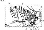
- FIG. 8 shows the third arrangement of the seating groups 100 in a deeper perspective, in which the individual shelves 114 are shown.
Landscapes
- Engineering & Computer Science (AREA)
- Mechanical Engineering (AREA)
- Aviation & Aerospace Engineering (AREA)
- Transportation (AREA)
- Seats For Vehicles (AREA)
- Vehicle Step Arrangements And Article Storage (AREA)
Abstract
Description
- Die vorliegende Erfindung betrifft ein variabel anordenbares Interieur in einem Fahrgastraum. Insbesondere betrifft die Erfindung eine variabel anordenbare Sitzgruppe in einem Fahrgastraum eines Personenbeförderungsfahrzeugs.
- Sitze auf einem drehbaren Träger für Kraftfahrzeuge, Busse oder Wohnanhänger sind im Stand der Technik bekannt. Das Dokument
DE 43 09 894 A1 beschreibt eine drehbare und ausrichtbare Platte, die auf dem Fußboden eines Verkehrsmittels befestigt ist. Die Platte ist über Kugellager drehbar gelagert und trägt einen Sitz. - Jedoch dient eine solche Drehbarkeit lediglich dem Nutzungskomfort und ermöglicht nicht eine variable Sitzplatzkonfiguration in einem Fahrgastraum.
- In der Luftfahrt besteht die Notwendigkeit, die Sitze in einer Passagierkabine unterschiedlich dicht anzuordnen. Das Dokument
DE 692 15 458 T2 beschreibt eine Sitzflächenanordnung für ein Flugzeug, in dem Sitze einer Sitzreihe wahlweise zusammengeschoben werden können. - Jedoch ist an den herkömmlichen Sitzanordnungen nachteilig, dass grundlegende Änderungen, beispielsweise der Reihenaufteilung oder Sitzgruppierung, nur durch den vollständigen Ausbau und Wiedereinbau mehrerer Sitze möglich sind. Dabei muss für jeden Sitz eine Vielzahl an Schraubverbindungen gelöst und am neuen Bestimmungsort des Sitzes angebracht werden.
- Somit besteht die Aufgabe der vorliegenden Erfindung darin, eine Technik zur variablen Anordnung von Sitzen in einem Fahrgastraum anzugeben. Eine weitere oder alternative Aufgabe besteht darin, eine Sitzkonfiguration in einem Fahrgastraum großflächig zu verändern, ohne die Sitze auszubauen.
- Diese Aufgabe oder Aufgaben werden durch eine Technik mit Merkmalen der unabhängigen Ansprüche gelöst. Vorteilhafte Ausführungsformen und Anwendungen der Erfindung sind Gegenstand der abhängigen Ansprüche und werden in der folgenden Beschreibung unter teilweiser Bezugnahme auf die Figuren näher erläutert.
- Gemäß einem Aspekt ist eine Sitzgruppe zur variablen Anordnung in einem Fahrgastraum eines Personenbeförderungsfahrzeugs bereitgestellt. Die Sitzgruppe umfasst mindestens zwei Sitzplätze und einen die mindestens zwei Sitzplätze tragenden Unterbau. Der Unterbau umfasst bodenseitig eine Verankerungsstelle. Die Verankerungsstelle ist in einem gelösten Zustand in eine Nutenführung einsetzbar. In einem arretierten Zustand ist die Verankerungsstelle in der Nutenführung lösbar arretiert. Die Sitzgruppe ist im gelösten Zustand bezüglich der Nutenführung verschiebbar und drehbar. Im arretierten Zustand ist die Sitzgruppe bezüglich der Nutenführung orts- und drehfest.
- Ausführungsbeispiele der Sitzgruppen können ohne Ausbau variable im Fahrgastraum angeordnet werden. Ausführungsbeispiele der Sitzgruppen können eine Veränderung der Anordnung der Sitzgruppen ohne Losteile ermöglichen. Beispielsweise kann die jeweilige Verankerungsstelle beim Verändern der Anordnung einzelner oder mehrerer solcher Sitzgruppen innerhalb des Fahrgastraums immer in der Nutenführung eingehängt bleiben. Die Verankerungsstelle und/oder die Sitzgruppe können im gelösten Zustand längs der Nutenführung verschiebbar sein. Die Verankerungsstelle und/oder die Sitzgruppe können im gelösten Zustand an jeder Längsposition der Nutenführung drehbar sein.
- Die Sitzgruppe kann beispielsweise um 90°, 180° oder 270° drehbar sein. Unabhängig von der orts- und drehfesten Anordnung der Sitzgruppe hinsichtlich des Unterbaus im arretierten Zustand können einzelne oder alle Sitzplätze einer Sitzgruppe in herkömmlicher weise drehbar und/oder kippbar bezüglich des Unterbaus sein.
- Der Begriff "bodenseitig" kann die von den Sitzplätzen abgewandte Seite des Unterbaus betreffen. Die Nutenführung kann am Boden des Fahrgastraums angeordnet sein.
- Im gelösten Zustand kann die Verankerungsstelle in einer Längsrichtung der Nutenführung beweglich angeordnet oder anordenbar sein. In einer Ebene senkrecht zur Längsrichtung der Nutenführung kann die Verankerungsstelle im gelösten Zustand formschlüssig in der Nutenführung angeordnet oder anordenbar sein. Die Nutenführung kann Schienen und/oder in Längsrichtung translationssymmetrische Profile umfassen.
- Die Verankerungsstelle kann einen zur Verbindung mit der Nutenführung ausgebildeten Nutenstein umfassen. Der Nutenstein kann mit der Nutenführung in Eingriff stehen oder in Eingriff bringbar sein. Der Nutenstein kann ein Schwalbenschwanz für eine Schwalbenschwanzverbindung in der Nutenführung sein. Alternativ kann der Nutzenstein ein T-Nutenstein sein.
- Die Drehbarkeit der Sitzgruppe im gelösten Zustand kann durch einen in der Nutenführung drehbaren Nutenstein (beispielsweise einen drehsymmetrischen Nutenstein) und/oder eine drehbare Lagerung des Nutensteins an der Verankerungsstelle realisiert sein.
- Die Verankerungsstelle kann zentral, beispielsweise mittig, unterhalb der Sitzplätze angeordnet sein. Jede Verankerungsstelle und/oder jede Sitzgruppe kann jeweils genau einen Nutenstein umfassen. Der Nutenstein kann auf einer Drehachse der Drehbeweglichkeit der Verankerungsstelle im gelösten Zustand angeordnet sein.
- Die mindestens zwei Sitzplätze der Sitzgruppe können aneinander angrenzend und/oder parallel zueinander ausgerichtet sein. Die Sitzplätze derselben Sitzgruppe können zueinander unbeweglich sein.
- Die Sitzgruppe kann eine oder mehrere Lüftungsöffnungen zum Ausstoßen oder Erzeugen eines Luftstroms aufweisen. Die Lüftungsöffnungen können in die Sitzgruppe, vorzugsweise in jedem der Sitzplätze, integriert sein. Jede Lüftungsöffnung kann hinsichtlich ihrer Position in der Sitzgruppe und/oder Richtung des Luftstroms jeweils einem der mindestens zwei Sitzplätze räumlich zugeordnet sein.
- Die Sitzgruppe kann eine oder mehrere Gepäckablagen umfassen. Die Gepäckablage kann in die Sitzgruppe, vorzugsweise in jedem der Sitzplätze, integriert sein. Die Gepäckablage kann ein Ablagefach und/oder ein elastisches Netz umfassen.
- Der Unterbau kann ferner Füße umfassen. Die Füße und die Verankerungsstelle des Unterbaus können im Wesentlichen in einer Ebene angeordnet sein. Die Verankerungsstelle kann im arretierten Zustand mit einer Zugkraft vorgespannt sein. Die Verankerungsstelle kann im arretierten Zustand mit der Nutenführung über die Zugkraft in vertikaler Richtung vorgespannt verbunden sein. Die Zugkraft kann die Füße des Unterbaus reibschlüssig auf einen Boden des Fahrgastraums drücken, auf oder in dem die Nutenführung befestigt ist. Durch den Reibschluss kann die Drehfestigkeit der Sitzgruppe im arretierten Zustand realisiert sein.
- Die Verankerungsstelle kann von den Füßen umgeben sein. Die Verankerungsstelle kann zwischen allen Füßen des Unterbaus, beispielsweise an einem geometrischen Schwerpunkt oder einer geometrischen Mitte aller Füße, angeordnet sein.
- Ein weiterer Aspekt betrifft ein Personenbeförderungsfahrzeug, insbesondere einen Bus, mit einem Fahrgastraum. Der Fahrgastraum umfasst mindestens eine am Boden des Fahrgastraums befestigte Nutenführung und mehrere Sitzgruppen gemäß dem vorgenannten Aspekt.
- Die Sitzgruppen sind in einer ersten Anordnung durch den arretierten Zustand der Verankerungsstellen orts- und drehfest auf dem Boden des Fahrgastraums angeordnet. Die Sitzgruppen im gelösten Zustand der Verankerungsstellen sind in eine zweite Anordnung längs der Nutenführung verschiebbar und/oder drehbar. Mittels des arretierten Zustands sind in der zweiten Anordnung die Sitzgruppen orts- und drehfest auf dem Boden des Fahrgastraums anordenbar.
- Das Personenbeförderungsfahrzeug kann ein Landfahrzeug (insbesondere ein Kraftfahrzeug oder ein Schienenfahrzeug), ein Luftfahrzeug und/oder ein Wasserfahrzeug sein. Insbesondere kann das Personenbeförderungsfahrzeug ein Personenkraftwagen, ein Zug, ein Reisezugwagen, eine Straßenbahn, ein Straßenbahnwagen, ein Schiff (insbesondere eine Personenfähre), ein Flugzeug oder ein Bus (insbesondere ein Oberleitungsbus) sein. Der Fahrgastraum kann ein Fahrgastraum eines Busses oder einer Straßenbahn, eine Fahrgastzelle eines Personenkraftwagens, ein Passagierdeck eines Schiffs oder eine Passagierkabine eines Flugzeugs sein.
- Die Verankerungsstellen können beim Übergang von der ersten Anordnung in die zweite Anordnung mit der Nutenführung in Eingriff bleiben. Der bei einem Einbau der Sitzgruppen bewerkstelligte Eingriff kann bei der Veränderung der Anordnung bestehen bleiben.
- Die Nutenführung kann mindestens eine Längsführung (beispielsweis in Längsrichtung des Personenbeförderungsfahrzeugs) umfassen. Alternativ oder ergänzend kann die Längsführung eine oder mehrere Querführungen umfassen, die sich beispielsweis senkrecht zur Längsrichtung des Personenbeförderungsfahrzeugs erstrecken. Die Längsführungen und Querführungen kann an Verzweigungspunkten oder Kreuzungspunkten durchgehend sein.
- Die Verankerungsstelle kann im gelösten Zustand entlang der durchgehend verbunden Nutenführung großflächig beweglich sein. Die mehreren Querführungen können (beispielsweise beidseitig) quer von der Längsführung abzweigen oder verzweigen. Die Sitzgruppe kann im gelösten Zustand entlang der Querführung und durchgehend zur Längsführung verfahrbar sein.
- Jede der Sitzgruppen kann einer der Querführungen (beispielsweise räumlich) zugeordnet sein. Bei der ersten Anordnung kann die Verankerungsstelle jeder Sitzgruppe in der zugeordneten Querführung arretiert sein. Bei der zweiten Anordnung kann die Verankerungsstelle jeder Sitzgruppe in der Längsführung arretiert sein.
- Die Nutenführung kann an mindestens einem ihrer Enden jeweils eine Einführöffnung aufweisen. Die Einführöffnung kann zur Einführung des Nutensteins im gelösten Zustand ausgebildet sein.
- Die zuvor beschriebenen bevorzugten Ausführungsformen und Merkmale der Erfindung sind beliebig miteinander kombinierbar. Weitere Einzelheiten und Vorteile der Erfindung werden im Folgenden unter Bezug auf die beigefügten Zeichnungen beschrieben. Es zeigen:
- Figur 1
- eine schematische perspektivische Darstellung eines Ausführungsbeispiels einer Sitzgruppe zur variablen Anordnung in einem Fahrgastraum;
- Figur 2
- eine schematische perspektivische Darstellung einer ersten Implementierung eines Unterbaus, die in jedem Ausführungsbeispiel einsetzbar ist;
- Figur 3
- eine schematische perspektivische Darstellung einer zweiten Implementierung des Unterbaus, die in jedem Ausführungsbeispiel einsetzbar ist;
- Figur 4
- einen schematischen Grundriss eines Ausführungsbeispiels eines Fahrgastraums, in dem jedes Ausführungsbeispiel der Sitzgruppe einsetzbar ist;
- Figur 5
- eine schematische perspektivische Darstellung einer ersten Anordnung von Sitzgruppen in einem beispielhaften Fahrgastraum;
- Figur 6
- eine schematische perspektivische Darstellung einer zweiten Anordnung von Sitzgruppen in einem beispielhaften Fahrgastraum;
- Figur 7
- eine schematische perspektivische Darstellung einer dritten Anordnung von Sitzgruppen in einem beispielhaften Fahrgastraum; und
- Figur 8
- eine schematische Darstellung der dritten Anordnung in einer zweiten Perspektive.
-
Figur 1 zeigt schematisch eine perspektivische Darstellung einer beispielhaften und allgemein mit Bezugszeichen 100 bezeichneten Sitzgruppe zur variablen Anordnung in einem Fahrgastraum eines Personenbeförderungsfahrzeugs. Das Personenbeförderungsfahrzeug kann ein Landfahrzeug, ein Wasserfahrzeug, ein Luftfahrzeug oder ein Raumfahrzeug sein. - Die Sitzgruppe 100 umfasst mindestens zwei Sitzplätze 102 und einen Unterbau 104, der die mindestens zwei Sitzplätze gemeinsam trägt. Der Unterbau 104 kann hinsichtlich Breite und Tiefe (d.h. in seinen horizontalen Abmessungen) mit den Abmessungen der gesamten Sitzfläche (und gegebenenfalls von Armlehnen) übereinstimmen.
- Der Unterbau 104 umfasst bodenseitig eine Verankerungsstelle 106, die in einem gelösten Zustand in eine Nutenführung einsetzbar ist, und die in einem arretierten Zustand in der Nutenführung lösbar arretiert ist. Die Sitzgruppe 100 ist im gelösten Zustand bezüglich der Nutenführung, d.h. bezüglich dem Fahrgastraum, verschiebbar und drehbar. Im arretierten Zustand der Verankerungsstelle 106 ist die Sitzgruppe 100 bezüglich der Nutenführung, d.h. bezüglich dem Fahrgastraum, orts- und drehfest.
- Die Verankerungsstelle 106 kann, wie beispielsweise im Ausführungsbeispiel der
Figur 1 gezeigt, über einen bodenseitigen oder bodennahen Querträger 108 und einen bodenseitigen oder bodennahen Längsträger 110 mit Füßen 112 des Unterbaus 104 mechanisch verbunden sein. Die Verankerungsstelle 106 ist zentral, beispielsweise mittig bezüglich der gesamten Sitzfläche der mindestens zwei Sitzplätze 102, an der Bodenseite des Unterbaus angeordnet. Vorzugsweise umfasst der Unterbau 104 einer Sitzgruppe 100 nur eine Verankerungsstelle 106. -
Figur 2 zeigt schematisch eine perspektivische Darstellung einer ersten Implementierung des Unterbaus 104. Die Implementierung ist in jedem Ausführungsbeispiel der Sitzgruppe 100 einsetzbar. Merkmale des Unterbaus 104, die mit jenen des ersten Ausführungsbeispiels der Sitzgruppe 100 übereinstimmen, sind mit entsprechenden Bezugszeichen versehen. - Durch die zentrale Verankerungsstelle 106 können mehrere solche Sitzgruppen entlang der Nutenführung verschoben und gedreht werden, um eine flexible Gestaltung des Innenraums des Personenbeförderungsfahrzeugs zu ermöglichen. Die Sitzgruppen 100 drehen sich um ihren eigenen zentralen Drehpunkt, der durch die Verankerungsstelle 106 definiert ist. Die Sitzgruppen 100 werden mithilfe von einem mechanischen Sicherungssystem am Verankerungspunkt 106 im arretierten Zustand der Verankerungsstelle 106 am Boden des Fahrgastraums befestigt. Die Arretierung ist bei Bedarf lösbar, d.h. in den gelösten Zustand zurückführbar, um die Sitzgruppen neu anzuordnen.
- Die Sitzgruppen 100 können zu einem Sitzsystem kombiniert werden, das aufgrund der Verankerungsstellen 106 sowohl verschiedene Sitzabstände als auch unterschiedliche Sitzanordnungen ermöglicht. Um die variable Anordnung ohne funktionale Einschränkungen zu gewährleisten, können bestimmte Funktionen in die Sitzgruppe 100 integriert sein. Beispielsweise kann jede Sitzgruppe 100, vorzugsweise jeder einzelne Sitzplatz 102 der Sitzgruppe 100, ein Gepäckablagefach 114 und Lüftungsöffnungen 116 aufweisen. Im in
Figur 1 gezeigten ersten Ausführungsbeispiel der Sitzgruppe 100 ist eine durchgehende Gepäckablage 114 unter den Sitzplätzen 102 einer Sitzgruppe 100 angeordnet. Die Lüftungsöffnungen 116 sind auf beiden Seiten einer Nackenstütze jedes Sitzplatzes 102 angeordnet. - In der in
Figur 2 gezeigten ersten Implementierung des Unterbaus 104 ist ein Nutenstein 118 bodenseitig an der Verankerungsstelle 106 angeordnet, beispielsweise am Querträger 108, der über die Längsträger 110 mit den Füßen 112 des Unterbaus verbunden ist. Im gelösten Zustand der Verankerungsstelle 106 steht der Nutenstein 118 bodenseitig an dem Unterbau 104 hervor und/oder ist vertikal beweglich, um in eine Nutenführung eingesetzt zu werden. Im arretierten Zustand der Verankerungsstelle 106 ist der Nutenstein 118 in vertikaler Richtung mit einer Zugkraft vorgespannt. Die Zugkraft kann eine reibschlüssige Verbindung des Nutensteins 118 in der Nutenführung bewirken und/oder die Füße 112 des Unterbaus 104 gegen einen Boden des Fahrgastraums drücken, so dass der Unterbau 104 auf dem Boden orts- und drehfest angeordnet ist. - Im gelösten Zustand der Verankerungsstelle 106 kann der Unterbau 104 (und damit die gesamte Sitzgruppe 100) längs der Nutenführung verschiebbar und um eine durch den Nutenstein 118 definierte Drehachse 120 an jeder Stelle der Nutenführung drehbar sein. Die Drehbeweglichkeit der Verankerungsstelle 106 im gelösten Zustand kann durch einen (wie in der ersten Implementierung in
Figur 2 gezeigt) drehsymmetrischen Nutenstein 118 realisiert sein. Alternativ oder zusätzlich kann der Nutenstein 118 drehbeweglich am Querträger 108 befestigt sein. - Die Zugspannung im arretierten Zustand der Verankerungsstelle 106 kann durch einen Spannverschluss mit einem Exzenter an der Verankerungsstelle 106 zwischen Nutenstein 118 und Querträger 108 realisiert sein. Alternativ oder ergänzend kann die Zugspannung durch anziehen einer Schraubverbindung zwischen Nutenstein 118 und Querträger 108 realisiert sein.
-
Figur 3 zeigt eine zweite Implementierung des Unterbaus 104. Die zweite Implementierung ist in jedem Ausführungsbeispiel der Sitzgruppe 100 einsetzbar und/oder als Weiterbildung der ersten Implementierung realisierbar. Einzelne Merkmale, die mit denen der ersten Implementierung übereinstimmen oder austauschbar sind, sind mit entsprechenden Bezugszeichen versehen. - Der Querträger 108 ist in der zweiten Implementierung entlang der Längsträger 110 verschiebbar im gelösten Zustand der Verankerungsstelle 106. Dadurch kann ein zusätzlicher Freiheitsgrad in der Positionierung der Sitzgruppe erreicht werden, beispielsweise ohne zusätzliche oder längere Nutenführungen am Boden des Fahrgastraums.
-
Figur 4 zeigt schematisch einen Grundriss eines Bodens 202 in einem Ausführungsbeispiel des Fahrgastraums 200. In den Boden 202 ist die Nutenführung 204 bündig eingelassen. Die Nutenführung 204 umfasst eine Längsführung 206 und sich unterbrechungsfrei von der Längsführung erstreckende Querführungen 208. Im inFigur 4 gezeigten Ausführungsbeispiel erstrecken sich die Querführungen 208 senkrecht zur Längsführung 206 und sind voneinander gleich beabstandet. Beispielsweise entspricht der Abstand zwischen benachbarten Querführungen 208 einem Mindestabstand zwischen den Sitzgruppen 100. - An den beiden Enden der Längsführung 206 sind Einführungsöffnungen 210 vorgesehen. Beispielsweise umfasst ein Profil des Nutenstein 118 ein erstes Quermaß und ein (vom Unterbau 104 weiter beabstandetes) zweites Quermaß, das größer als das erste Quermaß ist. Eine Öffnungsweite der Einführöffnungen 210 kann größer als das zweite Quermaß (oder gleich dem zweiten Quermaß) sein. Eine Öffnungsweite der Nutenführung 204 kann kleiner als das zweite Quermaß und größer als das erste Quermaß (oder gleich dem ersten Quermaß) sein.
-
Figur 5 zeigt schematisch eine perspektivische Darstellung einer ersten Anordnung mehrerer Sitzgruppen 100 in einem beispielhaften Fahrgastraum 200. Der Fahrgastraum 200 umfasst linksseitig und rechtsseitig jeweils eine zusammenhängende Nutenführung 204. In der in derFigur 5 gezeigten ersten Anordnung sind die Sitzgruppen 100 zueinander parallel, gleich beabstandet und in Fahrtrichtung ausgerichtet. - Die Nutenführung 204 umfasst auf jeder Fahrzeugseite eine parallel zur Längsrichtung (d.h. parallel zur Fahrtrichtung) sich erstreckende Längsführung und in räumlicher Zuordnung zu jeder der Sitzgruppen 100 jeweils eine mit der Längsführung durchgehend verbundene Querführung.
-
Figur 6 zeigt schematisch eine zweite Anordnung derselben Sitzgruppen 100 im selben beispielhaften Fahrgastraum 200 derFigur 5 . Durch Lösen der Verankerungsstelle 106, ohne dass der jeweilige Nutenstein an der Nutenführung 204 außer Eingriff kommt, sind die Sitzgruppen 100 um 90° zur Innenseite des Fahrgastraums 200 drehbar und entlang der jeweils zugeordneten Querführung 208 zur Außenseite des Fahrgastraums verschiebbar. Dadurch ist in der Mitte des Fahrgastraums ein breiter Durchgang zwischen den sich gegenüberstehenden Sitzgruppen 100 gebildet. -
Figur 7 zeigt schematisch eine perspektivische Darstellung einer dritten Anordnung derselben Sitzgruppen 100 im selben beispielhaften Fahrgastraum 200 derFiguren 5 und6 . Die Sitzgruppen 100 sind im gelösten Zustand der jeweiligen Verankerungsstelle 106 um 90° gegenüber der ersten Anordnung bzw. um 180° gegenüber der zweiten Anordnung gedreht. Ausgehend von der zweiten Anordnung derFigur 6 sind die Sitzgruppen ferner zur Mitte des Fahrgastraums hin entlang der jeweiligen Querführung 208 (beispielsweise über die kreuzende Längsführung hinaus) verschoben. So ist an den Fensterseiten des Fahrgastraums 200 jeweils ein Durchgang gebildet.Figur 8 zeigt die dritte Anordnung der Sitzgruppen 100 in einer tieferen Perspektive, in der die einzelnen Ablagen 114 dargestellt sind. - Obwohl die Erfindung in Bezug auf exemplarische Ausführungsbeispiele beschrieben worden ist, ist es für einen Fachmann ersichtlich, dass verschiedene Änderungen vorgenommen werden können und Äquivalente als Ersatz verwendet werden können. Ferner können viele Modifikationen vorgenommen werden, um eine bestimmte Situation oder ein bestimmtes Material an die Lehre der Erfindung anzupassen. Folglich ist die Erfindung nicht auf die offenbarten Ausführungsbeispiele beschränkt, sondern umfasst alle Ausführungsbeispiele, die in den Bereich der beigefügten Patentansprüche fallen.
-
- 100
- Sitzgruppe
- 102
- Sitzplätze
- 104
- Unterbau
- 106
- Verankerungsstelle
- 108
- Querträger
- 110
- Längsträger
- 112
- Füße des Unterbaus
- 114
- Ablage
- 116
- Lüftungsöffnungen
- 118
- Nutenstein
- 120
- Drehachse der Verankerungsstelle
- 200
- Fahrgastraum
- 202
- Boden des Fahrgastraums
- 204
- Nutenführung
- 206
- Längsführung der Nutenführung
- 208
- Querführung der Nutenführung
- 210
- Einführöffnung der Nutenführung
Claims (14)
- Sitzgruppe (100) zur variablen Anordnung in einem Fahrgastraum (200) eines Personenbeförderungsfahrzeugs, umfassend:mindestens zwei Sitzplätze (102); undeinen die mindestens zwei Sitzplätze (102) tragenden Unterbau (104), wobei der Unterbau (104) bodenseitig eine Verankerungsstelle (106) umfasst, die in einem gelösten Zustand in eine Nutenführung (204) einsetzbar ist, und die in einem arretierten Zustand in der Nutenführung (204) lösbar arretiert ist, wobei die Sitzgruppe (100) im gelösten Zustand bezüglich der Nutenführung (204) verschiebbar und drehbar ist, und im arretierten Zustand bezüglich der Nutenführung (204) orts- und drehfest ist.
- Sitzgruppe nach Anspruch 1, wobei im gelösten Zustand die Verankerungsstelle (106) in einer Längsrichtung der Nutenführung (204) beweglich und in einer Ebene senkrecht zur Längsrichtung formschlüssig in der Nutenführung angeordnet oder anordenbar ist.
- Sitzgruppe nach Anspruch 1 oder 2, wobei die Verankerungsstelle (106) einen zur Verbindung mit der Nutenführung (204) ausgebildeten Nutenstein (118) umfasst.
- Sitzgruppe nach einem der Ansprüche 1 bis 3, wobei die Verankerungsstelle (106) zentral unterhalb der Sitzplätze (102) angeordnet ist.
- Sitzgruppe nach Anspruch 3 und 4, wobei die Verankerungsstelle (106) nur einen Nutenstein (118) umfasst, der auf einer Drehachse (120) der Drehbeweglichkeit der Verankerungsstelle (106) im gelösten Zustand angeordnet ist.
- Sitzgruppe nach einem der Ansprüche 1 bis 5, wobei die mindestens zwei Sitzplätze (102) der Sitzgruppe (100) aneinander angrenzend und/oder parallel zueinander ausgerichtet sind.
- Sitzgruppe nach einem der Ansprüche 1 bis 6, wobei die Sitzgruppe (100) eine oder mehrere Belüftungsöffnungen (116) zum Erzeugen eines Luftstroms aufweist.
- Sitzgruppe nach einem der Ansprüche 1 bis 7, wobei die Sitzgruppe (100) eine oder mehrere Gepäckablagen umfasst.
- Sitzgruppe nach einem der Ansprüche 1 bis 8, wobei der Unterbau ferner Füße (112) umfasst, wobei die Verankerungsstelle (106) im arretierten Zustand mit der Nutenführung (204) mit einer Zugkraft vorgespannt ist, welche die Füße (112) reibschlüssig auf einen Boden (202) des Fahrgastraums (200) drückt.
- Personenbeförderungsfahrzeug, insbesondere Bus, mit einem Fahrgastraum (200), welcher umfasst:eine am Boden des Fahrgastraums befestigte Nutenführung (204); undmehrere Sitzgruppen (100) gemäß einem der Ansprüche 1 bis 9,wobei die Sitzgruppen (100) in einer ersten Anordnung durch den arretierten Zustand der Verankerungsstellen (106) orts- und drehfest auf dem Boden des Fahrgastraums (200) angeordnet sind, und wobei die Sitzgruppen (100) im gelösten Zustand der Verankerungsstellen (106) in eine zweite Anordnung längs der Nutenführung (204) verschiebbar und/oder drehbar sind.
- Personenbeförderungsfahrzeug nach Anspruch 10, wobei die Verankerungsstellen (106) beim Übergang von der ersten Anordnung in die zweite Anordnung mit den Nutenführung (204) in Eingriff bleiben.
- Personenbeförderungsfahrzeug nach Anspruch 10 oder 11, wobei die Nutenführung (204) mindestens eine Längsführung (206) und mehrere quer der Längsführung (206) abzweigende Querführungen (208) umfasst.
- Personenbeförderungsfahrzeug nach Anspruch 12, wobei jede Sitzgruppe (100) einer der Querführungen (208) zugeordnet ist, bei der ersten Anordnung die Verankerungsstelle jeder Sitzgruppe (100) in der zugeordneten Querführung (208) arretiert ist, und bei der zweiten Anordnung die Verankerungsstelle jeder Sitzgruppe (100) in der Längsführung (206) arretiert ist.
- Personenbeförderungsfahrzeug nach einem der Ansprüche 10 bis 13, wobei die Nutenführung an mindestens einem Ende der Nutenführung jeweils eine Einführöffnung (210) aufweist.
Priority Applications (1)
| Application Number | Priority Date | Filing Date | Title |
|---|---|---|---|
| PL18181912T PL3434510T3 (pl) | 2017-07-27 | 2018-07-05 | Zmienne wyposażenie wnętrza kabiny pasażerskiej |
Applications Claiming Priority (1)
| Application Number | Priority Date | Filing Date | Title |
|---|---|---|---|
| DE102017117046.4A DE102017117046A1 (de) | 2017-07-27 | 2017-07-27 | Variables Interieur eines Fahrgastraums |
Publications (2)
| Publication Number | Publication Date |
|---|---|
| EP3434510A1 true EP3434510A1 (de) | 2019-01-30 |
| EP3434510B1 EP3434510B1 (de) | 2021-09-01 |
Family
ID=62874648
Family Applications (1)
| Application Number | Title | Priority Date | Filing Date |
|---|---|---|---|
| EP18181912.9A Active EP3434510B1 (de) | 2017-07-27 | 2018-07-05 | Variables interieur eines fahrgastraums |
Country Status (5)
| Country | Link |
|---|---|
| EP (1) | EP3434510B1 (de) |
| CN (1) | CN109305068B (de) |
| DE (1) | DE102017117046A1 (de) |
| HU (1) | HUE056574T2 (de) |
| PL (1) | PL3434510T3 (de) |
Cited By (7)
| Publication number | Priority date | Publication date | Assignee | Title |
|---|---|---|---|---|
| US20210046855A1 (en) * | 2019-08-12 | 2021-02-18 | Speedinnov | Vehicle seat with improved storage space and associated vehicle |
| US20220379777A1 (en) * | 2021-05-27 | 2022-12-01 | International Truck Intellectual Property Company, Llc | Seating in a vehicle |
| US11772517B2 (en) | 2020-11-09 | 2023-10-03 | Ford Global Technologies, Llc | Vehicular system capable of adjusting a passenger compartment from a child seat arrangement to a second arrangement |
| US11904732B2 (en) | 2020-11-09 | 2024-02-20 | Ford Global Technologies, Llc | Vehicular system capable of adjusting a passenger compartment from a first arrangement to a child care arrangement |
| US12077068B2 (en) | 2020-11-09 | 2024-09-03 | Ford Global Technologies, Llc | Authorization-based adjustment of passenger compartment arrangement |
| EP3960539B1 (de) | 2020-08-27 | 2024-11-27 | Niesmann+Bischoff GmbH | Umbaubare sitzbank für ein freizeitfahrzeug |
| US12257932B2 (en) | 2020-11-09 | 2025-03-25 | Ford Global Technologies, Llc | Exterior imager utilized in adjusting a passenger compartment arrangement |
Families Citing this family (5)
| Publication number | Priority date | Publication date | Assignee | Title |
|---|---|---|---|---|
| CN111845473A (zh) * | 2019-04-28 | 2020-10-30 | 丹阳市车船装饰件有限公司 | 一种便于旋转调节的轻量化客车座椅 |
| CN110844083A (zh) * | 2019-10-11 | 2020-02-28 | 中国直升机设计研究所 | 一种运输直升机客舱座椅布置样式 |
| DE102019135314B4 (de) * | 2019-12-19 | 2025-07-03 | Bombardier Transportation Gmbh | Schienenfahrzeugwagen mit anpassbarer Abteilaufteilung |
| CN113120014A (zh) * | 2021-04-30 | 2021-07-16 | 深圳市人和智聚科技开发有限公司 | 一种车载结构紧凑型交通辅助工具 |
| EP4289663B1 (de) | 2022-06-08 | 2025-01-22 | Tricon AG | Fahrgastsitzanordnung für ein personentransportfahrzeug wie z.b. einen bus oder ein schienenfahrzeug |
Citations (4)
| Publication number | Priority date | Publication date | Assignee | Title |
|---|---|---|---|---|
| US20110140499A1 (en) * | 2009-12-14 | 2011-06-16 | James Masters | Modular transit system |
| EP2620366A1 (de) * | 2012-01-27 | 2013-07-31 | Bell Helicopter Textron Inc. | Besatzungsstationssitzanordnung in einem Fahrzeug |
| GB2531167A (en) * | 2014-10-08 | 2016-04-13 | Grm Consulting Ltd | Vehicle seating system |
| WO2016199919A1 (ja) * | 2015-06-12 | 2016-12-15 | テイ・エス テック株式会社 | 移動調整システム |
Family Cites Families (5)
| Publication number | Priority date | Publication date | Assignee | Title |
|---|---|---|---|---|
| BE540946A (de) * | 1954-09-25 | |||
| US5284379A (en) | 1991-09-04 | 1994-02-08 | The Boeing Company | Convertible aircraft passenger seats |
| IT1259299B (it) | 1992-04-24 | 1996-03-11 | Piastra rotante ed orientabile per sedili preferibilmente di autoveicoli autopullman e camper | |
| FR2785780B1 (fr) * | 1998-11-13 | 2001-01-19 | Alstom Technology | Siege tournant a mouvement perfectionne, notamment pour vehicule ferroviaire |
| DE102009056715A1 (de) * | 2009-12-04 | 2011-06-09 | Bröcker, Matthias, Dipl.-Des. | Ausstattung für Verkehrsmittel, insbesondere Schienenverkehrsmittel |
-
2017
- 2017-07-27 DE DE102017117046.4A patent/DE102017117046A1/de not_active Withdrawn
-
2018
- 2018-07-05 HU HUE18181912A patent/HUE056574T2/hu unknown
- 2018-07-05 PL PL18181912T patent/PL3434510T3/pl unknown
- 2018-07-05 EP EP18181912.9A patent/EP3434510B1/de active Active
- 2018-07-24 CN CN201810819182.3A patent/CN109305068B/zh active Active
Patent Citations (4)
| Publication number | Priority date | Publication date | Assignee | Title |
|---|---|---|---|---|
| US20110140499A1 (en) * | 2009-12-14 | 2011-06-16 | James Masters | Modular transit system |
| EP2620366A1 (de) * | 2012-01-27 | 2013-07-31 | Bell Helicopter Textron Inc. | Besatzungsstationssitzanordnung in einem Fahrzeug |
| GB2531167A (en) * | 2014-10-08 | 2016-04-13 | Grm Consulting Ltd | Vehicle seating system |
| WO2016199919A1 (ja) * | 2015-06-12 | 2016-12-15 | テイ・エス テック株式会社 | 移動調整システム |
Cited By (8)
| Publication number | Priority date | Publication date | Assignee | Title |
|---|---|---|---|---|
| US20210046855A1 (en) * | 2019-08-12 | 2021-02-18 | Speedinnov | Vehicle seat with improved storage space and associated vehicle |
| EP3960539B1 (de) | 2020-08-27 | 2024-11-27 | Niesmann+Bischoff GmbH | Umbaubare sitzbank für ein freizeitfahrzeug |
| US11772517B2 (en) | 2020-11-09 | 2023-10-03 | Ford Global Technologies, Llc | Vehicular system capable of adjusting a passenger compartment from a child seat arrangement to a second arrangement |
| US11904732B2 (en) | 2020-11-09 | 2024-02-20 | Ford Global Technologies, Llc | Vehicular system capable of adjusting a passenger compartment from a first arrangement to a child care arrangement |
| US12077068B2 (en) | 2020-11-09 | 2024-09-03 | Ford Global Technologies, Llc | Authorization-based adjustment of passenger compartment arrangement |
| US12257932B2 (en) | 2020-11-09 | 2025-03-25 | Ford Global Technologies, Llc | Exterior imager utilized in adjusting a passenger compartment arrangement |
| US20220379777A1 (en) * | 2021-05-27 | 2022-12-01 | International Truck Intellectual Property Company, Llc | Seating in a vehicle |
| US11958387B2 (en) * | 2021-05-27 | 2024-04-16 | International Truck Intellectual Property Company, Llc | Seating in a vehicle |
Also Published As
| Publication number | Publication date |
|---|---|
| BR102018015040A2 (pt) | 2019-06-04 |
| HUE056574T2 (hu) | 2022-02-28 |
| RU2018126599A3 (de) | 2022-01-21 |
| EP3434510B1 (de) | 2021-09-01 |
| CN109305068B (zh) | 2022-08-23 |
| DE102017117046A1 (de) | 2019-01-31 |
| PL3434510T3 (pl) | 2021-12-27 |
| RU2018126599A (ru) | 2020-01-20 |
| CN109305068A (zh) | 2019-02-05 |
Similar Documents
| Publication | Publication Date | Title |
|---|---|---|
| EP3434510B1 (de) | Variables interieur eines fahrgastraums | |
| EP2440457B1 (de) | System und verfahren zum herstellen einer fahrzeugkabine | |
| EP2358593B1 (de) | Vorrichtung zum befestigen eines objekts an einer schiene | |
| DE102018108803B4 (de) | Seitenführung, Seitenführungsgruppe, Frachtdeck, Flugzeug | |
| DE102010029563B4 (de) | Kanallager | |
| DE102015117709A1 (de) | Adapterschienensystem und Verfahren zum Befestigen eines Objekts an einer Fußbodenschiene in einem Transportmittel | |
| DE102016109789B4 (de) | Sitzsystem für eine Kabine eines Transportmittels mit kompaktierbarer Sitzreihe | |
| EP1336563B1 (de) | Montageeinrichtung für ein Riegelelement | |
| DE102008048745B4 (de) | Arretiervorrichtung für ein an einer Schiene arretierbares Objekt, Verwendung einer derartigen Arretiervorrichtung und Verkehrsmittel mit einer derartigen Vorrichtung | |
| DE102019134746A1 (de) | Komponentensystem zur Innenausstattung eines Luftfahrzeugs | |
| EP3458362B1 (de) | Flexibles schienensystem zum befestigen von objekten an einem fussboden in einer kabine eines transportmittels | |
| DE102010055365A1 (de) | Tischeinrichtung für eine Sitzanlage eines Kraftwagens | |
| DE102016108858A1 (de) | Vorrichtung zur Anbringung einer Sitzanordnung an einem Fahrzeug und Fahrzeug | |
| DE102018123251B4 (de) | Schienensystem zum Befestigen von Einbauten in einer Kabine eines Fahrzeugs | |
| EP2679498B1 (de) | Sitzanordnung mit längsverschiebbaren Sitzreihen | |
| EP3594057A1 (de) | Wohnmobil | |
| DE102004046070A1 (de) | Befestigungssystem für Einrichtungselemente in Kraftfahrzeugen | |
| DE102016111983B4 (de) | Modulares Schienensystem | |
| DE102018110336A1 (de) | Bodenbefestigungsbaugruppe sowie Sitzbefestigungssystem, Sitz und Flugzeug mit einer Bodenbefestigungsbaugruppe | |
| DE102016111994A1 (de) | Modulares Schienensystem | |
| DE102019111622A1 (de) | Ablagevorrichtung für ein Fortbewegungsmittel und Fortbewegungsmittel | |
| DE102017104601A1 (de) | Linearführungsmechanismus für einen Passagiersitz | |
| WO2015000601A1 (de) | Vorrichtung zum festlegen eines gegenstandes | |
| DE102018101836A1 (de) | Befestigungssystem zum Befestigen von Einbauten in einem Fahrzeug | |
| DE102016122993A1 (de) | Vorrichtung zum Führen einer Leitung im Fussboden einer Luftfahrzeugkabine |
Legal Events
| Date | Code | Title | Description |
|---|---|---|---|
| PUAI | Public reference made under article 153(3) epc to a published international application that has entered the european phase |
Free format text: ORIGINAL CODE: 0009012 |
|
| STAA | Information on the status of an ep patent application or granted ep patent |
Free format text: STATUS: THE APPLICATION HAS BEEN PUBLISHED |
|
| AK | Designated contracting states |
Kind code of ref document: A1 Designated state(s): AL AT BE BG CH CY CZ DE DK EE ES FI FR GB GR HR HU IE IS IT LI LT LU LV MC MK MT NL NO PL PT RO RS SE SI SK SM TR |
|
| AX | Request for extension of the european patent |
Extension state: BA ME |
|
| RAP1 | Party data changed (applicant data changed or rights of an application transferred) |
Owner name: MAN TRUCK & BUS SE |
|
| STAA | Information on the status of an ep patent application or granted ep patent |
Free format text: STATUS: REQUEST FOR EXAMINATION WAS MADE |
|
| 17P | Request for examination filed |
Effective date: 20190729 |
|
| RBV | Designated contracting states (corrected) |
Designated state(s): AL AT BE BG CH CY CZ DE DK EE ES FI FR GB GR HR HU IE IS IT LI LT LU LV MC MK MT NL NO PL PT RO RS SE SI SK SM TR |
|
| STAA | Information on the status of an ep patent application or granted ep patent |
Free format text: STATUS: EXAMINATION IS IN PROGRESS |
|
| 17Q | First examination report despatched |
Effective date: 20200626 |
|
| REG | Reference to a national code |
Ref country code: DE Ref legal event code: R079 Ref document number: 502018006795 Country of ref document: DE Free format text: PREVIOUS MAIN CLASS: B60N0002005000 Ipc: B61D0033000000 |
|
| GRAP | Despatch of communication of intention to grant a patent |
Free format text: ORIGINAL CODE: EPIDOSNIGR1 |
|
| STAA | Information on the status of an ep patent application or granted ep patent |
Free format text: STATUS: GRANT OF PATENT IS INTENDED |
|
| RIC1 | Information provided on ipc code assigned before grant |
Ipc: B60N 2/24 20060101ALI20210331BHEP Ipc: B60N 2/06 20060101ALI20210331BHEP Ipc: B60N 2/14 20060101ALI20210331BHEP Ipc: B60N 2/005 20060101ALI20210331BHEP Ipc: B61D 33/00 20060101AFI20210331BHEP |
|
| INTG | Intention to grant announced |
Effective date: 20210422 |
|
| GRAS | Grant fee paid |
Free format text: ORIGINAL CODE: EPIDOSNIGR3 |
|
| GRAA | (expected) grant |
Free format text: ORIGINAL CODE: 0009210 |
|
| STAA | Information on the status of an ep patent application or granted ep patent |
Free format text: STATUS: THE PATENT HAS BEEN GRANTED |
|
| AK | Designated contracting states |
Kind code of ref document: B1 Designated state(s): AL AT BE BG CH CY CZ DE DK EE ES FI FR GB GR HR HU IE IS IT LI LT LU LV MC MK MT NL NO PL PT RO RS SE SI SK SM TR |
|
| REG | Reference to a national code |
Ref country code: GB Ref legal event code: FG4D Free format text: NOT ENGLISH |
|
| REG | Reference to a national code |
Ref country code: CH Ref legal event code: EP Ref country code: AT Ref legal event code: REF Ref document number: 1425940 Country of ref document: AT Kind code of ref document: T Effective date: 20210915 |
|
| REG | Reference to a national code |
Ref country code: DE Ref legal event code: R096 Ref document number: 502018006795 Country of ref document: DE |
|
| REG | Reference to a national code |
Ref country code: IE Ref legal event code: FG4D Free format text: LANGUAGE OF EP DOCUMENT: GERMAN |
|
| REG | Reference to a national code |
Ref country code: SE Ref legal event code: TRGR |
|
| REG | Reference to a national code |
Ref country code: NL Ref legal event code: FP |
|
| REG | Reference to a national code |
Ref country code: LT Ref legal event code: MG9D |
|
| PG25 | Lapsed in a contracting state [announced via postgrant information from national office to epo] |
Ref country code: NO Free format text: LAPSE BECAUSE OF FAILURE TO SUBMIT A TRANSLATION OF THE DESCRIPTION OR TO PAY THE FEE WITHIN THE PRESCRIBED TIME-LIMIT Effective date: 20211201 Ref country code: LT Free format text: LAPSE BECAUSE OF FAILURE TO SUBMIT A TRANSLATION OF THE DESCRIPTION OR TO PAY THE FEE WITHIN THE PRESCRIBED TIME-LIMIT Effective date: 20210901 Ref country code: BG Free format text: LAPSE BECAUSE OF FAILURE TO SUBMIT A TRANSLATION OF THE DESCRIPTION OR TO PAY THE FEE WITHIN THE PRESCRIBED TIME-LIMIT Effective date: 20211201 Ref country code: HR Free format text: LAPSE BECAUSE OF FAILURE TO SUBMIT A TRANSLATION OF THE DESCRIPTION OR TO PAY THE FEE WITHIN THE PRESCRIBED TIME-LIMIT Effective date: 20210901 Ref country code: ES Free format text: LAPSE BECAUSE OF FAILURE TO SUBMIT A TRANSLATION OF THE DESCRIPTION OR TO PAY THE FEE WITHIN THE PRESCRIBED TIME-LIMIT Effective date: 20210901 Ref country code: FI Free format text: LAPSE BECAUSE OF FAILURE TO SUBMIT A TRANSLATION OF THE DESCRIPTION OR TO PAY THE FEE WITHIN THE PRESCRIBED TIME-LIMIT Effective date: 20210901 Ref country code: RS Free format text: LAPSE BECAUSE OF FAILURE TO SUBMIT A TRANSLATION OF THE DESCRIPTION OR TO PAY THE FEE WITHIN THE PRESCRIBED TIME-LIMIT Effective date: 20210901 |
|
| PG25 | Lapsed in a contracting state [announced via postgrant information from national office to epo] |
Ref country code: LV Free format text: LAPSE BECAUSE OF FAILURE TO SUBMIT A TRANSLATION OF THE DESCRIPTION OR TO PAY THE FEE WITHIN THE PRESCRIBED TIME-LIMIT Effective date: 20210901 Ref country code: GR Free format text: LAPSE BECAUSE OF FAILURE TO SUBMIT A TRANSLATION OF THE DESCRIPTION OR TO PAY THE FEE WITHIN THE PRESCRIBED TIME-LIMIT Effective date: 20211202 |
|
| REG | Reference to a national code |
Ref country code: HU Ref legal event code: AG4A Ref document number: E056574 Country of ref document: HU |
|
| PG25 | Lapsed in a contracting state [announced via postgrant information from national office to epo] |
Ref country code: IS Free format text: LAPSE BECAUSE OF FAILURE TO SUBMIT A TRANSLATION OF THE DESCRIPTION OR TO PAY THE FEE WITHIN THE PRESCRIBED TIME-LIMIT Effective date: 20220101 Ref country code: SM Free format text: LAPSE BECAUSE OF FAILURE TO SUBMIT A TRANSLATION OF THE DESCRIPTION OR TO PAY THE FEE WITHIN THE PRESCRIBED TIME-LIMIT Effective date: 20210901 Ref country code: SK Free format text: LAPSE BECAUSE OF FAILURE TO SUBMIT A TRANSLATION OF THE DESCRIPTION OR TO PAY THE FEE WITHIN THE PRESCRIBED TIME-LIMIT Effective date: 20210901 Ref country code: RO Free format text: LAPSE BECAUSE OF FAILURE TO SUBMIT A TRANSLATION OF THE DESCRIPTION OR TO PAY THE FEE WITHIN THE PRESCRIBED TIME-LIMIT Effective date: 20210901 Ref country code: PT Free format text: LAPSE BECAUSE OF FAILURE TO SUBMIT A TRANSLATION OF THE DESCRIPTION OR TO PAY THE FEE WITHIN THE PRESCRIBED TIME-LIMIT Effective date: 20220103 Ref country code: EE Free format text: LAPSE BECAUSE OF FAILURE TO SUBMIT A TRANSLATION OF THE DESCRIPTION OR TO PAY THE FEE WITHIN THE PRESCRIBED TIME-LIMIT Effective date: 20210901 Ref country code: CZ Free format text: LAPSE BECAUSE OF FAILURE TO SUBMIT A TRANSLATION OF THE DESCRIPTION OR TO PAY THE FEE WITHIN THE PRESCRIBED TIME-LIMIT Effective date: 20210901 Ref country code: AL Free format text: LAPSE BECAUSE OF FAILURE TO SUBMIT A TRANSLATION OF THE DESCRIPTION OR TO PAY THE FEE WITHIN THE PRESCRIBED TIME-LIMIT Effective date: 20210901 |
|
| REG | Reference to a national code |
Ref country code: DE Ref legal event code: R097 Ref document number: 502018006795 Country of ref document: DE |
|
| PLBE | No opposition filed within time limit |
Free format text: ORIGINAL CODE: 0009261 |
|
| STAA | Information on the status of an ep patent application or granted ep patent |
Free format text: STATUS: NO OPPOSITION FILED WITHIN TIME LIMIT |
|
| PG25 | Lapsed in a contracting state [announced via postgrant information from national office to epo] |
Ref country code: DK Free format text: LAPSE BECAUSE OF FAILURE TO SUBMIT A TRANSLATION OF THE DESCRIPTION OR TO PAY THE FEE WITHIN THE PRESCRIBED TIME-LIMIT Effective date: 20210901 |
|
| 26N | No opposition filed |
Effective date: 20220602 |
|
| PG25 | Lapsed in a contracting state [announced via postgrant information from national office to epo] |
Ref country code: SI Free format text: LAPSE BECAUSE OF FAILURE TO SUBMIT A TRANSLATION OF THE DESCRIPTION OR TO PAY THE FEE WITHIN THE PRESCRIBED TIME-LIMIT Effective date: 20210901 |
|
| PG25 | Lapsed in a contracting state [announced via postgrant information from national office to epo] |
Ref country code: MC Free format text: LAPSE BECAUSE OF FAILURE TO SUBMIT A TRANSLATION OF THE DESCRIPTION OR TO PAY THE FEE WITHIN THE PRESCRIBED TIME-LIMIT Effective date: 20210901 |
|
| REG | Reference to a national code |
Ref country code: CH Ref legal event code: PL |
|
| GBPC | Gb: european patent ceased through non-payment of renewal fee |
Effective date: 20220705 |
|
| REG | Reference to a national code |
Ref country code: BE Ref legal event code: MM Effective date: 20220731 |
|
| PG25 | Lapsed in a contracting state [announced via postgrant information from national office to epo] |
Ref country code: LU Free format text: LAPSE BECAUSE OF NON-PAYMENT OF DUE FEES Effective date: 20220705 Ref country code: LI Free format text: LAPSE BECAUSE OF NON-PAYMENT OF DUE FEES Effective date: 20220731 Ref country code: CH Free format text: LAPSE BECAUSE OF NON-PAYMENT OF DUE FEES Effective date: 20220731 |
|
| PG25 | Lapsed in a contracting state [announced via postgrant information from national office to epo] |
Ref country code: GB Free format text: LAPSE BECAUSE OF NON-PAYMENT OF DUE FEES Effective date: 20220705 Ref country code: BE Free format text: LAPSE BECAUSE OF NON-PAYMENT OF DUE FEES Effective date: 20220731 |
|
| PG25 | Lapsed in a contracting state [announced via postgrant information from national office to epo] |
Ref country code: IE Free format text: LAPSE BECAUSE OF NON-PAYMENT OF DUE FEES Effective date: 20220705 |
|
| PG25 | Lapsed in a contracting state [announced via postgrant information from national office to epo] |
Ref country code: MK Free format text: LAPSE BECAUSE OF FAILURE TO SUBMIT A TRANSLATION OF THE DESCRIPTION OR TO PAY THE FEE WITHIN THE PRESCRIBED TIME-LIMIT Effective date: 20210901 Ref country code: CY Free format text: LAPSE BECAUSE OF FAILURE TO SUBMIT A TRANSLATION OF THE DESCRIPTION OR TO PAY THE FEE WITHIN THE PRESCRIBED TIME-LIMIT Effective date: 20210901 |
|
| REG | Reference to a national code |
Ref country code: AT Ref legal event code: MM01 Ref document number: 1425940 Country of ref document: AT Kind code of ref document: T Effective date: 20230705 |
|
| PG25 | Lapsed in a contracting state [announced via postgrant information from national office to epo] |
Ref country code: MT Free format text: LAPSE BECAUSE OF FAILURE TO SUBMIT A TRANSLATION OF THE DESCRIPTION OR TO PAY THE FEE WITHIN THE PRESCRIBED TIME-LIMIT Effective date: 20210901 |
|
| PG25 | Lapsed in a contracting state [announced via postgrant information from national office to epo] |
Ref country code: AT Free format text: LAPSE BECAUSE OF NON-PAYMENT OF DUE FEES Effective date: 20230705 |
|
| PG25 | Lapsed in a contracting state [announced via postgrant information from national office to epo] |
Ref country code: AT Free format text: LAPSE BECAUSE OF NON-PAYMENT OF DUE FEES Effective date: 20230705 |
|
| PGFP | Annual fee paid to national office [announced via postgrant information from national office to epo] |
Ref country code: PL Payment date: 20250626 Year of fee payment: 8 |
|
| PGFP | Annual fee paid to national office [announced via postgrant information from national office to epo] |
Ref country code: TR Payment date: 20250624 Year of fee payment: 8 |
|
| PGFP | Annual fee paid to national office [announced via postgrant information from national office to epo] |
Ref country code: HU Payment date: 20250709 Year of fee payment: 8 |
|
| PGFP | Annual fee paid to national office [announced via postgrant information from national office to epo] |
Ref country code: NL Payment date: 20250724 Year of fee payment: 8 |
|
| PGFP | Annual fee paid to national office [announced via postgrant information from national office to epo] |
Ref country code: DE Payment date: 20250728 Year of fee payment: 8 |
|
| PGFP | Annual fee paid to national office [announced via postgrant information from national office to epo] |
Ref country code: IT Payment date: 20250721 Year of fee payment: 8 |
|
| PGFP | Annual fee paid to national office [announced via postgrant information from national office to epo] |
Ref country code: FR Payment date: 20250725 Year of fee payment: 8 |
|
| PGFP | Annual fee paid to national office [announced via postgrant information from national office to epo] |
Ref country code: SE Payment date: 20250725 Year of fee payment: 8 |
|
| PGFP | Annual fee paid to national office [announced via postgrant information from national office to epo] |
Ref country code: AT Payment date: 20260410 Year of fee payment: 5 |