EP3433111B1 - Lauffläche für einen reifen - Google Patents
Lauffläche für einen reifen Download PDFInfo
- Publication number
- EP3433111B1 EP3433111B1 EP17715228.7A EP17715228A EP3433111B1 EP 3433111 B1 EP3433111 B1 EP 3433111B1 EP 17715228 A EP17715228 A EP 17715228A EP 3433111 B1 EP3433111 B1 EP 3433111B1
- Authority
- EP
- European Patent Office
- Prior art keywords
- tread
- equal
- grooves
- depth
- width
- Prior art date
- Legal status (The legal status is an assumption and is not a legal conclusion. Google has not performed a legal analysis and makes no representation as to the accuracy of the status listed.)
- Active
Links
- 238000005096 rolling process Methods 0.000 description 11
- 230000000903 blocking effect Effects 0.000 description 3
- 230000007423 decrease Effects 0.000 description 2
- 230000002787 reinforcement Effects 0.000 description 2
- 230000009977 dual effect Effects 0.000 description 1
- 230000002349 favourable effect Effects 0.000 description 1
- 238000010438 heat treatment Methods 0.000 description 1
- 238000012986 modification Methods 0.000 description 1
- 230000004048 modification Effects 0.000 description 1
- 238000000465 moulding Methods 0.000 description 1
- 230000001737 promoting effect Effects 0.000 description 1
Images

Classifications
-
- B—PERFORMING OPERATIONS; TRANSPORTING
- B60—VEHICLES IN GENERAL
- B60C—VEHICLE TYRES; TYRE INFLATION; TYRE CHANGING; CONNECTING VALVES TO INFLATABLE ELASTIC BODIES IN GENERAL; DEVICES OR ARRANGEMENTS RELATED TO TYRES
- B60C11/00—Tyre tread bands; Tread patterns; Anti-skid inserts
- B60C11/03—Tread patterns
- B60C11/11—Tread patterns in which the raised area of the pattern consists only of isolated elements, e.g. blocks
-
- B—PERFORMING OPERATIONS; TRANSPORTING
- B60—VEHICLES IN GENERAL
- B60C—VEHICLE TYRES; TYRE INFLATION; TYRE CHANGING; CONNECTING VALVES TO INFLATABLE ELASTIC BODIES IN GENERAL; DEVICES OR ARRANGEMENTS RELATED TO TYRES
- B60C11/00—Tyre tread bands; Tread patterns; Anti-skid inserts
- B60C11/03—Tread patterns
- B60C11/0327—Tread patterns characterised by special properties of the tread pattern
- B60C11/033—Tread patterns characterised by special properties of the tread pattern by the void or net-to-gross ratios of the patterns
-
- B—PERFORMING OPERATIONS; TRANSPORTING
- B60—VEHICLES IN GENERAL
- B60C—VEHICLE TYRES; TYRE INFLATION; TYRE CHANGING; CONNECTING VALVES TO INFLATABLE ELASTIC BODIES IN GENERAL; DEVICES OR ARRANGEMENTS RELATED TO TYRES
- B60C11/00—Tyre tread bands; Tread patterns; Anti-skid inserts
- B60C11/03—Tread patterns
- B60C11/12—Tread patterns characterised by the use of narrow slits or incisions, e.g. sipes
- B60C11/1236—Tread patterns characterised by the use of narrow slits or incisions, e.g. sipes with special arrangements in the tread pattern
- B60C11/125—Tread patterns characterised by the use of narrow slits or incisions, e.g. sipes with special arrangements in the tread pattern arranged at the groove bottom
-
- B—PERFORMING OPERATIONS; TRANSPORTING
- B60—VEHICLES IN GENERAL
- B60C—VEHICLE TYRES; TYRE INFLATION; TYRE CHANGING; CONNECTING VALVES TO INFLATABLE ELASTIC BODIES IN GENERAL; DEVICES OR ARRANGEMENTS RELATED TO TYRES
- B60C11/00—Tyre tread bands; Tread patterns; Anti-skid inserts
- B60C11/03—Tread patterns
- B60C11/0306—Patterns comprising block rows or discontinuous ribs
-
- B—PERFORMING OPERATIONS; TRANSPORTING
- B60—VEHICLES IN GENERAL
- B60C—VEHICLE TYRES; TYRE INFLATION; TYRE CHANGING; CONNECTING VALVES TO INFLATABLE ELASTIC BODIES IN GENERAL; DEVICES OR ARRANGEMENTS RELATED TO TYRES
- B60C11/00—Tyre tread bands; Tread patterns; Anti-skid inserts
- B60C11/03—Tread patterns
- B60C11/0311—Patterns comprising tread lugs arranged parallel or oblique to the axis of rotation
-
- B—PERFORMING OPERATIONS; TRANSPORTING
- B60—VEHICLES IN GENERAL
- B60C—VEHICLE TYRES; TYRE INFLATION; TYRE CHANGING; CONNECTING VALVES TO INFLATABLE ELASTIC BODIES IN GENERAL; DEVICES OR ARRANGEMENTS RELATED TO TYRES
- B60C11/00—Tyre tread bands; Tread patterns; Anti-skid inserts
- B60C11/03—Tread patterns
- B60C11/12—Tread patterns characterised by the use of narrow slits or incisions, e.g. sipes
- B60C11/1204—Tread patterns characterised by the use of narrow slits or incisions, e.g. sipes with special shape of the sipe
- B60C11/1218—Three-dimensional shape with regard to depth and extending direction
-
- B—PERFORMING OPERATIONS; TRANSPORTING
- B60—VEHICLES IN GENERAL
- B60C—VEHICLE TYRES; TYRE INFLATION; TYRE CHANGING; CONNECTING VALVES TO INFLATABLE ELASTIC BODIES IN GENERAL; DEVICES OR ARRANGEMENTS RELATED TO TYRES
- B60C11/00—Tyre tread bands; Tread patterns; Anti-skid inserts
- B60C11/03—Tread patterns
- B60C11/12—Tread patterns characterised by the use of narrow slits or incisions, e.g. sipes
- B60C11/1259—Depth of the sipe
-
- B—PERFORMING OPERATIONS; TRANSPORTING
- B60—VEHICLES IN GENERAL
- B60C—VEHICLE TYRES; TYRE INFLATION; TYRE CHANGING; CONNECTING VALVES TO INFLATABLE ELASTIC BODIES IN GENERAL; DEVICES OR ARRANGEMENTS RELATED TO TYRES
- B60C11/00—Tyre tread bands; Tread patterns; Anti-skid inserts
- B60C11/03—Tread patterns
- B60C2011/0337—Tread patterns characterised by particular design features of the pattern
- B60C2011/0339—Grooves
- B60C2011/0341—Circumferential grooves
- B60C2011/0344—Circumferential grooves provided at the equatorial plane
-
- B—PERFORMING OPERATIONS; TRANSPORTING
- B60—VEHICLES IN GENERAL
- B60C—VEHICLE TYRES; TYRE INFLATION; TYRE CHANGING; CONNECTING VALVES TO INFLATABLE ELASTIC BODIES IN GENERAL; DEVICES OR ARRANGEMENTS RELATED TO TYRES
- B60C11/00—Tyre tread bands; Tread patterns; Anti-skid inserts
- B60C11/03—Tread patterns
- B60C2011/0337—Tread patterns characterised by particular design features of the pattern
- B60C2011/0339—Grooves
- B60C2011/0341—Circumferential grooves
- B60C2011/0353—Circumferential grooves characterised by width
-
- B—PERFORMING OPERATIONS; TRANSPORTING
- B60—VEHICLES IN GENERAL
- B60C—VEHICLE TYRES; TYRE INFLATION; TYRE CHANGING; CONNECTING VALVES TO INFLATABLE ELASTIC BODIES IN GENERAL; DEVICES OR ARRANGEMENTS RELATED TO TYRES
- B60C11/00—Tyre tread bands; Tread patterns; Anti-skid inserts
- B60C11/03—Tread patterns
- B60C2011/0337—Tread patterns characterised by particular design features of the pattern
- B60C2011/0339—Grooves
- B60C2011/0358—Lateral grooves, i.e. having an angle of 45 to 90 degees to the equatorial plane
- B60C2011/036—Narrow grooves, i.e. having a width of less than 3 mm
-
- B—PERFORMING OPERATIONS; TRANSPORTING
- B60—VEHICLES IN GENERAL
- B60C—VEHICLE TYRES; TYRE INFLATION; TYRE CHANGING; CONNECTING VALVES TO INFLATABLE ELASTIC BODIES IN GENERAL; DEVICES OR ARRANGEMENTS RELATED TO TYRES
- B60C11/00—Tyre tread bands; Tread patterns; Anti-skid inserts
- B60C11/03—Tread patterns
- B60C2011/0337—Tread patterns characterised by particular design features of the pattern
- B60C2011/0339—Grooves
- B60C2011/0358—Lateral grooves, i.e. having an angle of 45 to 90 degees to the equatorial plane
- B60C2011/0365—Lateral grooves, i.e. having an angle of 45 to 90 degees to the equatorial plane characterised by width
-
- B—PERFORMING OPERATIONS; TRANSPORTING
- B60—VEHICLES IN GENERAL
- B60C—VEHICLE TYRES; TYRE INFLATION; TYRE CHANGING; CONNECTING VALVES TO INFLATABLE ELASTIC BODIES IN GENERAL; DEVICES OR ARRANGEMENTS RELATED TO TYRES
- B60C2200/00—Tyres specially adapted for particular applications
- B60C2200/06—Tyres specially adapted for particular applications for heavy duty vehicles
- B60C2200/065—Tyres specially adapted for particular applications for heavy duty vehicles for construction vehicles
Definitions
- the present invention relates to a tread for an off-road vehicle tire carrying very heavy loads.
- the tires of civil engineering vehicles are used in twin mounting on a rear axle.
- their large dimensions and in particular their large tread width and relatively small radii of gyration (comparable to those which one has with heavy vehicles) it is observed that the tires of civil engineering machines used in twin mounts are subjected to very strong constraints when the vehicle on which they are mounted is maneuvering turn. It should be noted that this type of maneuver is very frequent on these vehicles whether empty or fully loaded and has a significant impact on wear (both on the regularity of wear and on the speed of wear).
- this structure reinforcement comprising radially under the tread a plurality of layers of material reinforced by cables oriented in appropriate directions.
- radial direction is meant in this document a direction which is perpendicular to the axis of rotation of the tire (this direction corresponds to the direction of the thickness of the tread).
- Radial plane plane containing the axis of rotation of the tire.
- Equatorial median plane plane perpendicular to the axis of rotation of the tire and dividing the tire into two equal halves.
- transverse or axial direction is meant a direction parallel to the axis of rotation of the tire.
- circumferential direction is meant a direction which is tangent to any circle centered on the axis of rotation. This direction is perpendicular to both the axial direction and a radial direction.
- a rib is an element of relief material formed on a tread, this element of material extending in the circumferential direction and generally goes around the tire.
- a rib comprises two side walls and a contact face, the latter forming a part of the running surface of the strip to come into contact with the roadway during driving.
- the grooves are spaces created during molding between facing walls of material, these walls being connected together by a bottom. These grooves can take different widths and depths.
- a tread has a maximum thickness Ht of material to be used in rolling. Once this maximum thickness is reached, the tire can be replaced by a new tire or else retreaded, that is to say be provided with a new tread.
- the volume of material to be used corresponds for the tires of the invention to the amount of material located between the running surface in new condition and a virtual surface parallel to the rolling surface in new condition and passing through the points the innermost of the grooves formed in the tread.
- the surface hollow ratio of a sculpture is equal to the ratio between the surface of the hollows formed by the grooves and the total surface (contact surface of the relief elements and surface of the hollows).
- a low hollow rate indicates a large contact surface of the relief elements and a small hollow surface between these elements.
- the volume trough rate of a tread pattern in new condition is equal to the ratio between the volume of the grooves formed in the tread and the total volume of said tread comprising the volume of material to be used and the volume of the grooves.
- a low volume hollow rate indicates a small volume of hollow relative to the volume of material to be used on the tread.
- tire running conditions or conditions of use are those defined in particular by the E.T.R.T.O. for European use or any equivalent standard depending on the country concerned; these conditions of use specify the reference inflation pressure corresponding to the load capacity of the tire indicated by its load index and its speed code. These conditions of use can also be called “nominal conditions” or “conditions of use”.
- the present invention aims to provide a tread for tires for off-road vehicles carrying very heavy loads.
- the tread according to the invention is provided with a tread allowing both an improvement in the wear performance while retaining an appropriate grip and regardless of the state of wear of this strip.
- This invention is more particularly applicable to very wide treads, namely a width at least equal to 600 mm, intended for tires used at least in part in dual mounting on a rear axle of an off-road vehicle such as a civil engineering machine.
- the invention relates to a tread for an off-road vehicle tire carrying very heavy loads.
- This tread has a total width Wt greater than 600 mm and a thickness Ht of material to be used, this tread being provided with at least three main grooves of general circumferential orientation and of depth at least equal to 60 mm. These at least three main grooves divide the tread into intermediate ribs and into edge ribs, the edge ribs axially delimiting the tread and having a width at most equal to a quarter of the total width Wt of the strip.
- At least one of the intermediate ribs is provided with a plurality of fine grooves having a depth H1 and delimiting blades of material of average circumferential length B1 less than twice the depth H1. These fine grooves are oriented in the transverse direction corresponding to the axial direction of the tire or in an oblique direction, that is to say in an orientation making an angle at most equal to 45 degrees with the transverse or axial direction of the tire.
- Each intermediate rib has an average width which is at most equal to a quarter of the total width Wt of the tread and is at least equal to 0.75 times the thickness Ht of material to be used.
- This tread is characterized in that the fine grooves have, over a height H12 at least equal to 65% of their depth H1, a width which is at most equal to the value obtained from the following mathematical expression: 0.04 B 1 . H 1 (Four percent of the square root of the product of B1 by H1).
- the angle of the fine grooves is at most equal to 20 degrees with the transverse direction of the tire.
- fine grooves satisfying the relation according to which the depth H1 is at least equal to 0.5 times the average circumferential length B1 of the blades of material delimited by the fine grooves are favorable on the wear performance of tires subjected to engine torques.
- the forces applied by the ground to the tread in the direction of travel can be very high, which results in a shear stress on the blades of larger material when cornering. than during torque transfer phases, in particular under engine torque.
- Limiting the width of the ribs is essential so that the amplitude of variation of the forces over the width of each blade of material is limited during a turn of small radius of gyration.
- the intermediate ribs provided with fine grooves are such that the average circumferential length B1 between two fine grooves is at most equal to the depth H1 and at least equal to 0.4 times this same depth H1.
- each main circumferential groove has a width at least equal to 6% of its depth so as to be able to close in the passage of contact with the ground and generate contact pressures between the facing walls. Even more preferably, the width of each main circumferential groove is at most equal to 15% of its depth.
- the depth H1 of the fine grooves is equal to or close to the depth of the main circumferential grooves.
- At least part of the fine grooves also comprise means for blocking relative movements. facing walls delimiting these fine grooves.
- These blocking means are all the more useful as the B1 / H1 ratio decreases and as a function of use the coefficient of friction between the walls of the fine grooves can decrease due to the presence of foreign bodies.
- the edge ribs axially delimiting the tread may be provided with a plurality of wide grooves and fine grooves of average depth H2 delimiting blocks of average circumferential length B2, the average depth H2 being less than 1.2 times the average circumferential length B2, each fine groove having an average width which is less than the value of the expression: 0.04 B 2 .
- H 2
- the tread may include among the intermediate ribs at least one rib devoid of any fine groove.
- a tread according to the invention may comprise at least one intermediate rib provided with wide grooves oriented transversely or obliquely.
- all the intermediate ribs are provided with fine grooves.
- the fine grooves formed on the intermediate ribs have variable widths between the new rolling surface and the bottom of these fine grooves while respecting, between the rolling surface and the bottom, the relationship mathematical : 0.04 B 1 . H 1 .
- the fine grooves have an orientation making an angle at most equal to 20 degrees with the transverse or axial direction of the tire to be more effective in wear.
- the depth H1 of the fine grooves in the intermediate zone is less than the depth of the grooves in the edge zone in order to obtain a good compromise between the heating of the edge regions and the resistance to attack in the region central.
- the value of B1 may be substantially similar for all the intermediate ribs or may vary from one intermediate rib to another. In particular, it may be advantageous to have a higher H1 / B1 ratio for the ribs closest to the equatorial median plane when there are at least three intermediate ribs.
- the invention is used in tires for vehicles carrying heavy loads such as vehicles intended for off-road uses, that is to say off the road network, in particular in mines.
- the figure 1 shows a partial view of a tread 10 of a tire according to the invention intended to equip in a first phase the front axle of an off-road vehicle of the rigid dumper type (“ dumper ” in English) for carry very heavy loads and then the rear axle of a similar vehicle.
- This 40.00 R 57 radial tire comprises a tread 10 intended to provide a connection between the tire and the ground on which the vehicle is traveling.
- This tread 10 has a total width Wt greater than 600 mm and a tread surface 100 intended to come into contact with the ground.
- This strip has a total thickness Ht of material to be used which is at least equal to 60 mm.
- This tread 10 comprises four main circumferential grooves 1, 2, 3, 4 of average width at least equal to 6 mm on the tread surface of the tire in new condition and of depth at most equal to the thickness of material to use.
- the three intermediate ribs have the same width which is less than a quarter of the total width of the tread.
- Each of these three ribs is provided with a plurality of fine grooves, respectively 61, 62, 63, these fine grooves being oriented in the transverse direction perpendicular to the circumferential direction and therefore parallel to the direction of the axis of rotation of the tire. provided with this band.
- Each fine transverse groove 61, 62, 63 opens on either side in a main groove circumferential. Furthermore, these fine transverse grooves are offset from one another in the circumferential direction from one row to another.
- These fine transverse grooves 61, 62, 63 with the main circumferential grooves delimit in each circumferential row 51, 52, 53 a plurality of elements or blade of material 71, 72, 73 respectively whose average height corresponds to the average depth H1 of said fine grooves.
- the width of intermediate ribs provided with fine grooves is at least equal to 0.75 times the thickness Ht of the material to be used.
- the average circumferential length B1 is defined as being less than the depth H1 of the fine grooves.
- the widths of the fine grooves have widths at most equal to the value of the mathematical expression: 0.04 B 1 . H 1 .
- Axially outside the edge ribs are circumferentially continuous and devoid of grooves.
- These fine grooves 63 define with the main grooves 3 and 4 a plurality of material elements 73 having a height equal to the depth H1 of the incisions and a circumferential length B1 on the rolling surface 100.
- the other grooves transverse fines 61, 62 have the same dimensional characteristics; of course the person skilled in the art can create variations of these characteristics depending on the objective sought.
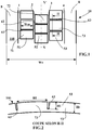
- the figure 3 shows another variant of tread according to the invention which has been the subject of tests.
- This tread 10 for a radial tire of dimension 40.00 R 57 intended to equip in a first phase the front axle of a vehicle outside the rigid dumper type road (“dumper” in English) to carry very heavy loads and then the rear axle of a similar vehicle.
- This tread has a total width Wt equal to 999 mm and is intended to come into contact with the ground via a rolling surface 100 during driving.
- This tread 10 comprises five main circumferential grooves 1, 2, 3, 4, 5 of average width equal to 8 mm with the exception of the groove in the middle position which has an average width equal to 10 mm in new condition .
- These main grooves have a depth equal to 102 mm with the exception of the most axially outermost main grooves, the latter having a depth equal to 108 mm.
- These main grooves have widths suitable both for closing and generating contact pressures between their opposite walls when passing through the contact while allowing sufficient thermal evacuation out of contact.
- edge ribs have an average width equal to 135 mm while the intermediate ribs have an average width equal to 172 mm for those closest to the edge ribs and 174 mm for the ribs closest to the equatorial median plane, the trace of which in the figure is indicated by line XX '.
- Each intermediate rib is provided with a plurality of fine grooves of width 2.5 mm extending in the thickness of the tread over a height H1.
- These fine grooves of small width are oriented obliquely, that is to say in a direction making an angle of 15 degrees with the axis of rotation of the tire.
- These fine grooves define with the main circumferential grooves a plurality of material blades whose average circumferential length B1 measured in the direction of the circumferential direction is equal to the average height of the blades. This average height corresponds to the average depth of said fine grooves.
- the fine grooves have a part of height H12 equal to 71 mm over which their width is equal to 2.5 mm and in addition a wider part of height H11 equal to 30 mm. On this wider part close to the new rolling surface, the width does not satisfy the relationship 0.04 B 1 .
- each edge rib is provided with a plurality of wide grooves having an average width of 45 mm and the same depth as the main circumferential grooves separating the edges of the intermediate ribs, that is to say 108 mm. Alternating with these wide grooves, provision is made for narrow grooves 2.5 mm wide.
- the figure 4 shows a section along a plane whose trace on the figure 3 is indicated by line IV-IV.
- the tire exhibits a significantly increased wear performance both in a straight line and in turns, while retaining thermal and grip performance equivalent to the control, regardless of the state of wear of the tread. rolling.
Landscapes
- Engineering & Computer Science (AREA)
- Mechanical Engineering (AREA)
- Tires In General (AREA)
Claims (11)
- Laufstreifen (10) für einen Reifen eines Offroad-Fahrzeugs, das sehr schwere Lasten trägt, wobei dieser Laufstreifen (10) eine Gesamtbreite Wt, die größer als 600 mm ist, und eine Dicke Ht von abzunutzendem Material aufweist, wobei dieser Laufstreifen (10) mit wenigstens drei Hauptrillen (1, 2, 3, 4) versehen ist, die im Wesentlichen in Umfangsrichtung ausgerichtet sind und eine Tiefe von wenigstens 60 mm aufweisen, wobei diese wenigstens drei Hauptrillen (1, 2, 3, 4) den Laufstreifen (10) in Zwischenrippen (51, 52, 53) und in Randrippen (8) aufteilen, wobei die Randrippen (8) den Laufstreifen (10) axial begrenzen, wobei diese Randrippen (8) eine Breite aufweisen, die höchstens gleich einem Viertel der Gesamtbreite Wt des Laufstreifen (10) ist,
wobei wenigstens eine der Zwischenrippen (51, 52, 53) mit mehreren feinen Rillen (61, 62, 63) versehen ist, wobei sich jede feine Rille (61, 62, 63) auf beiden Seiten in eine Hauptrille (1, 2, 3, 4) öffnet und eine Tiefe H1 aufweist, wobei diese feinen Rillen (61, 62, 63) mit den jeweiligen Hauptrillen (1, 2, 3, 4) Materiallamellen (71, 72, 73) mit einer mittleren Länge in Umfangsrichtung B1 begrenzen, die kleiner als das Zweifache der Tiefe H1 ist, wobei diese feinen Rillen (61, 62, 63) in der Querrichtung, die der axialen Richtung des Reifens entspricht, ausgerichtet sind, oder in einer schrägen Richtung, das heißt mit einer Ausrichtung, die einen Winkel von höchstens 45 Grad mit der Querrichtung oder axialen Richtung des Reifens bildet, wobei jede Zwischenrippe (51, 52, 53) eine mittlere Breite aufweist, welche höchstens gleich einem Viertel der Gesamtbreite Wt des Laufstreifen (10) ist und mindestens gleich dem 0,75-Fachen der Dicke Ht von abzunutzendem Material ist,
wobei dieser Laufstreifen (10) dadurch gekennzeichnet ist, dass:
die feinen Rillen (61, 62, 63) auf einer Höhe H12, die mindestens gleich 65 % ihrer Tiefe H1 ist, eine Breite aufweisen, welche höchstens gleich dem Wert ist, der aus dem folgenden mathematischen Ausdruck erhalten wird:
- Laufstreifen (10) nach Anspruch 1, dadurch gekennzeichnet, dass der Winkel der feinen Rillen (61, 62, 63) mit der Querrichtung des Reifens höchstens 20 Grad beträgt.
- Laufstreifen (10) nach Anspruch 1 oder Anspruch 2, dadurch gekennzeichnet, dass die mit feinen Rillen (61, 62, 63) versehenen Zwischenrippen (51, 52, 53) so beschaffen sind, dass die mittlere Länge in Umfangsrichtung B1 zwischen zwei feinen Rillen (61, 62, 63) höchstens gleich der Tiefe H1 und mindestens gleich dem 0,4-Fachen dieser Tiefe H1 ist.
- Laufstreifen (10) nach einem der Ansprüche 1 bis 3, dadurch gekennzeichnet, dass jede in Umfangsrichtung verlaufende Hauptrille (1, 2, 3, 4) eine Breite aufweist, die mindestens gleich 6 % ihrer Tiefe ist, so dass sie sich beim Durchlaufen des Kontakts mit dem Boden schließen und Kontaktdrücke zwischen den einander gegenüberliegenden Wänden erzeugen kann.
- Laufstreifen (10) nach Anspruch 4, dadurch gekennzeichnet, dass jede in Umfangsrichtung verlaufende Hauptrille (1, 2, 3, 4) eine Breite aufweist, die höchstens gleich 15 % ihrer Tiefe ist.
- Laufstreifen (10) nach einem der Ansprüche 1 bis 5, dadurch gekennzeichnet, dass die Tiefe H1 der feinen Rillen (61, 62, 63) gleich der Tiefe der in Umfangsrichtung verlaufenden Hauptrillen (1, 2, 3, 4) ist oder dieser nahekommt.
- Laufstreifen (10) nach einem der Ansprüche 1 bis 6, dadurch gekennzeichnet, dass die Randrippen (8), die den Laufstreifen (10) axial begrenzen, mit mehreren breiten Rillen (85, 86) und feinen Rillen (65, 66) mit einer mittleren Tiefe H2 versehen sind, welche Blöcke (75, 76) mit einer mittleren Länge in Umfangsrichtung B2 begrenzen, wobei die mittlere Tiefe H2 kleiner als das 1,2-Fache der mittleren Länge in Umfangsrichtung B2 ist, wobei jede feine Rille (65, 66) eine mittlere Breite aufweist, welche kleiner als der Wert des folgenden Ausdrucks ist:

- Laufstreifen (10) nach einem der Ansprüche 1 bis 7, dadurch gekennzeichnet, dass wenigstens eine Zwischenrippe mit keiner feinen Rille versehen ist.
- Laufstreifen (10) nach einem der Ansprüche 1 bis 7, dadurch gekennzeichnet, dass wenigstens eine Zwischenrippe mit breiten Rillen versehen ist, die quer oder schräg ausgerichtet sind.
- Laufstreifen (10) nach einem der Ansprüche 1 bis 7, dadurch gekennzeichnet, dass alle Zwischenrippen (51, 52, 53) mit feinen Rillen (61, 62, 63) versehen sind.
- Laufstreifen (10) nach einem der Ansprüche 1 bis 10, dadurch gekennzeichnet, dass die an den Zwischenrippen (51, 52, 53) ausgebildeten feinen Rillen (61, 62, 63) Breiten aufweisen, die zwischen der Lauffläche im Neuzustand und dem Boden dieser feinen Rillen (61, 62, 63) variabel sind, wobei sie gleichzeitig zwischen der Lauffläche und dem Boden der folgenden mathematischen Beziehung genügen:

Applications Claiming Priority (2)
| Application Number | Priority Date | Filing Date | Title |
|---|---|---|---|
| FR1652623A FR3049218A1 (fr) | 2016-03-25 | 2016-03-25 | Bande de roulement incisee pour pneu hors la route |
| PCT/FR2017/050569 WO2017162953A1 (fr) | 2016-03-25 | 2017-03-14 | Bande de roulement pour un pneu |
Publications (2)
| Publication Number | Publication Date |
|---|---|
| EP3433111A1 EP3433111A1 (de) | 2019-01-30 |
| EP3433111B1 true EP3433111B1 (de) | 2020-07-15 |
Family
ID=56741128
Family Applications (1)
| Application Number | Title | Priority Date | Filing Date |
|---|---|---|---|
| EP17715228.7A Active EP3433111B1 (de) | 2016-03-25 | 2017-03-14 | Lauffläche für einen reifen |
Country Status (6)
| Country | Link |
|---|---|
| US (1) | US11192403B2 (de) |
| EP (1) | EP3433111B1 (de) |
| CN (1) | CN108778782B (de) |
| BR (1) | BR112018069514B1 (de) |
| FR (1) | FR3049218A1 (de) |
| WO (1) | WO2017162953A1 (de) |
Families Citing this family (4)
| Publication number | Priority date | Publication date | Assignee | Title |
|---|---|---|---|---|
| JP6954867B2 (ja) * | 2018-06-19 | 2021-10-27 | 株式会社ブリヂストン | 重荷重用タイヤ |
| FR3095984B1 (fr) | 2019-05-16 | 2022-08-19 | Michelin & Cie | Bande de roulement de pneumatique pour véhicule lourd de type génie civil |
| JP7473784B2 (ja) * | 2020-02-13 | 2024-04-24 | 横浜ゴム株式会社 | 空気入りタイヤ |
| FR3124436B1 (fr) | 2021-06-24 | 2024-05-03 | Michelin & Cie | Bande de roulement de pneumatique pour un véhicule lourd de génie civil avec un compromis robustesse/ thermique amélioré |
Family Cites Families (21)
| Publication number | Priority date | Publication date | Assignee | Title |
|---|---|---|---|---|
| IT1276320B1 (it) * | 1994-02-22 | 1997-10-28 | Pirelli | Pneumatico per veicoli da trasporto medio/pesante con battistrada di tipo universale |
| GB9902449D0 (en) * | 1999-02-05 | 1999-03-24 | Sumitomo Rubber Ind | Tread for a pneumatic tyre |
| US7281555B2 (en) * | 2001-06-07 | 2007-10-16 | Bridgestone Corporation | Off-the-road tire |
| JP2004262295A (ja) * | 2003-02-28 | 2004-09-24 | Bridgestone Corp | 建設車両用重荷重用空気入りタイヤ |
| WO2004101247A1 (ja) * | 2003-05-13 | 2004-11-25 | Bridgestone Corporation | タイヤ加硫金型および空気入りタイヤ |
| JP2006160195A (ja) * | 2004-12-10 | 2006-06-22 | Yokohama Rubber Co Ltd:The | 空気入りタイヤ |
| JP5002202B2 (ja) * | 2006-07-05 | 2012-08-15 | 株式会社ブリヂストン | 建設車両用空気入りタイヤ |
| JP4805762B2 (ja) * | 2006-09-05 | 2011-11-02 | 株式会社ブリヂストン | 建設車両用タイヤ |
| JP2008114738A (ja) * | 2006-11-06 | 2008-05-22 | Bridgestone Corp | 重荷重用タイヤおよびその使用方法 |
| JP5123981B2 (ja) * | 2010-04-27 | 2013-01-23 | 住友ゴム工業株式会社 | 重荷重用タイヤ |
| JP5753404B2 (ja) * | 2011-02-28 | 2015-07-22 | 株式会社ブリヂストン | 建設車両用ラジアルタイヤ |
| FR2972962B1 (fr) * | 2011-03-25 | 2013-03-29 | Michelin Soc Tech | Bande de roulement optimisee en usure pour pneu de poids lourd |
| JP5956765B2 (ja) * | 2012-02-10 | 2016-07-27 | 株式会社ブリヂストン | 建設車両用空気入りラジアルタイヤ |
| FR2993500B1 (fr) * | 2012-07-20 | 2015-02-06 | Michelin & Cie | Bande de roulement pour pneu d'essieu moteur de poids lourd et pneu |
| JP5695099B2 (ja) * | 2013-01-30 | 2015-04-01 | 株式会社ブリヂストン | 建設車両用空気入りタイヤ |
| JP6134585B2 (ja) * | 2013-06-03 | 2017-05-24 | 株式会社ブリヂストン | 建設車両用空気入りタイヤ |
| US10195907B2 (en) * | 2013-07-30 | 2019-02-05 | Sumitomo Rubber Industries, Ltd. | Heavy-duty tire |
| FR3017075B1 (fr) * | 2014-02-03 | 2016-02-12 | Michelin & Cie | Bande de roulement pour pneu poids lourd |
| JP5993406B2 (ja) * | 2014-06-04 | 2016-09-14 | 住友ゴム工業株式会社 | 空気入りタイヤ |
| FR3022493B1 (fr) * | 2014-06-24 | 2016-07-01 | Michelin & Cie | Bande de roulement incisee pour pneu genie civil |
| JP6671874B2 (ja) * | 2015-07-09 | 2020-03-25 | 株式会社ブリヂストン | 建設車両用タイヤ |
-
2016
- 2016-03-25 FR FR1652623A patent/FR3049218A1/fr active Pending
-
2017
- 2017-03-14 EP EP17715228.7A patent/EP3433111B1/de active Active
- 2017-03-14 WO PCT/FR2017/050569 patent/WO2017162953A1/fr active Application Filing
- 2017-03-14 CN CN201780019262.4A patent/CN108778782B/zh active Active
- 2017-03-14 BR BR112018069514-9A patent/BR112018069514B1/pt active IP Right Grant
- 2017-03-14 US US16/087,010 patent/US11192403B2/en active Active
Non-Patent Citations (1)
| Title |
|---|
| None * |
Also Published As
| Publication number | Publication date |
|---|---|
| CN108778782A (zh) | 2018-11-09 |
| US11192403B2 (en) | 2021-12-07 |
| BR112018069514A2 (pt) | 2019-01-29 |
| BR112018069514B1 (pt) | 2022-03-03 |
| WO2017162953A1 (fr) | 2017-09-28 |
| EP3433111A1 (de) | 2019-01-30 |
| US20190100057A1 (en) | 2019-04-04 |
| FR3049218A1 (fr) | 2017-09-29 |
| CN108778782B (zh) | 2020-10-02 |
Similar Documents
| Publication | Publication Date | Title |
|---|---|---|
| EP2834089B1 (de) | Reifenlauffläche für eine durch ein schwerlastfahrzeug getriebene achse | |
| EP3433111B1 (de) | Lauffläche für einen reifen | |
| EP2643171B1 (de) | Lkw-reifen für ein anhängerfahrzeug | |
| EP3160773B1 (de) | Lauffläche mit inzisionen für reifen ziviler baufahrzeuge | |
| EP2563604B1 (de) | Profil für einen reifen für schwerlastfahrzeuge vom anhängertyp | |
| EP2736735B1 (de) | Laufflächenstruktur für reifen eines hoch- und tiefbaufahrzeugs | |
| EP2911894B1 (de) | Entwicklungsfähiger laufstreifen | |
| EP3648991B1 (de) | Reifen dessen lauffläche wellenförmige nuten aufweist | |
| EP3237232B1 (de) | Lauffläche für winterreifen eines schwerlastfahrzeugs | |
| EP3303007B1 (de) | Verbesserte reifenlauffläche | |
| FR2744067A1 (fr) | Bande de roulement pour pneumatique | |
| EP2509804B1 (de) | Verfahren für den entwurf eines reifens und reifen | |
| EP1283115B1 (de) | Oberflächenprofil der Elemente der Reifenlauffläche | |
| EP2961619B1 (de) | Verbesserte reifenlauffläche für tiefbau | |
| EP3439897B1 (de) | Reifenlauffläche | |
| WO2017182762A1 (fr) | Bande de roulement de pneu comprenant des découpures de différentes profondeurs | |
| WO2009115529A1 (fr) | Systeme de suspension de vehicule et pneumatique pour vehicule | |
| EP3383673B1 (de) | Reifenlaufflächenblockgeometrie | |
| EP4319989A1 (de) | Reifen für ein landwirtschaftliches nutzfahrzeug mit gemischter verwendung |
Legal Events
| Date | Code | Title | Description |
|---|---|---|---|
| STAA | Information on the status of an ep patent application or granted ep patent |
Free format text: STATUS: UNKNOWN |
|
| STAA | Information on the status of an ep patent application or granted ep patent |
Free format text: STATUS: THE INTERNATIONAL PUBLICATION HAS BEEN MADE |
|
| PUAI | Public reference made under article 153(3) epc to a published international application that has entered the european phase |
Free format text: ORIGINAL CODE: 0009012 |
|
| STAA | Information on the status of an ep patent application or granted ep patent |
Free format text: STATUS: REQUEST FOR EXAMINATION WAS MADE |
|
| 17P | Request for examination filed |
Effective date: 20181025 |
|
| AK | Designated contracting states |
Kind code of ref document: A1 Designated state(s): AL AT BE BG CH CY CZ DE DK EE ES FI FR GB GR HR HU IE IS IT LI LT LU LV MC MK MT NL NO PL PT RO RS SE SI SK SM TR |
|
| AX | Request for extension of the european patent |
Extension state: BA ME |
|
| DAV | Request for validation of the european patent (deleted) | ||
| DAX | Request for extension of the european patent (deleted) | ||
| STAA | Information on the status of an ep patent application or granted ep patent |
Free format text: STATUS: EXAMINATION IS IN PROGRESS |
|
| 17Q | First examination report despatched |
Effective date: 20191014 |
|
| REG | Reference to a national code |
Ref country code: DE Ref legal event code: R079 Ref document number: 602017019792 Country of ref document: DE Free format text: PREVIOUS MAIN CLASS: B60C0011120000 Ipc: B60C0011030000 |
|
| GRAP | Despatch of communication of intention to grant a patent |
Free format text: ORIGINAL CODE: EPIDOSNIGR1 |
|
| STAA | Information on the status of an ep patent application or granted ep patent |
Free format text: STATUS: GRANT OF PATENT IS INTENDED |
|
| RIC1 | Information provided on ipc code assigned before grant |
Ipc: B60C 11/11 20060101ALI20200108BHEP Ipc: B60C 11/12 20060101ALI20200108BHEP Ipc: B60C 11/03 20060101AFI20200108BHEP |
|
| INTG | Intention to grant announced |
Effective date: 20200205 |
|
| GRAS | Grant fee paid |
Free format text: ORIGINAL CODE: EPIDOSNIGR3 |
|
| GRAA | (expected) grant |
Free format text: ORIGINAL CODE: 0009210 |
|
| STAA | Information on the status of an ep patent application or granted ep patent |
Free format text: STATUS: THE PATENT HAS BEEN GRANTED |
|
| AK | Designated contracting states |
Kind code of ref document: B1 Designated state(s): AL AT BE BG CH CY CZ DE DK EE ES FI FR GB GR HR HU IE IS IT LI LT LU LV MC MK MT NL NO PL PT RO RS SE SI SK SM TR |
|
| REG | Reference to a national code |
Ref country code: CH Ref legal event code: EP Ref country code: GB Ref legal event code: FG4D Free format text: NOT ENGLISH |
|
| REG | Reference to a national code |
Ref country code: IE Ref legal event code: FG4D Free format text: LANGUAGE OF EP DOCUMENT: FRENCH |
|
| REG | Reference to a national code |
Ref country code: DE Ref legal event code: R096 Ref document number: 602017019792 Country of ref document: DE |
|
| REG | Reference to a national code |
Ref country code: AT Ref legal event code: REF Ref document number: 1290615 Country of ref document: AT Kind code of ref document: T Effective date: 20200815 |
|
| REG | Reference to a national code |
Ref country code: LT Ref legal event code: MG4D |
|
| REG | Reference to a national code |
Ref country code: AT Ref legal event code: MK05 Ref document number: 1290615 Country of ref document: AT Kind code of ref document: T Effective date: 20200715 |
|
| REG | Reference to a national code |
Ref country code: NL Ref legal event code: MP Effective date: 20200715 |
|
| PG25 | Lapsed in a contracting state [announced via postgrant information from national office to epo] |
Ref country code: GR Free format text: LAPSE BECAUSE OF FAILURE TO SUBMIT A TRANSLATION OF THE DESCRIPTION OR TO PAY THE FEE WITHIN THE PRESCRIBED TIME-LIMIT Effective date: 20201016 Ref country code: NO Free format text: LAPSE BECAUSE OF FAILURE TO SUBMIT A TRANSLATION OF THE DESCRIPTION OR TO PAY THE FEE WITHIN THE PRESCRIBED TIME-LIMIT Effective date: 20201015 Ref country code: BG Free format text: LAPSE BECAUSE OF FAILURE TO SUBMIT A TRANSLATION OF THE DESCRIPTION OR TO PAY THE FEE WITHIN THE PRESCRIBED TIME-LIMIT Effective date: 20201015 Ref country code: AT Free format text: LAPSE BECAUSE OF FAILURE TO SUBMIT A TRANSLATION OF THE DESCRIPTION OR TO PAY THE FEE WITHIN THE PRESCRIBED TIME-LIMIT Effective date: 20200715 Ref country code: SE Free format text: LAPSE BECAUSE OF FAILURE TO SUBMIT A TRANSLATION OF THE DESCRIPTION OR TO PAY THE FEE WITHIN THE PRESCRIBED TIME-LIMIT Effective date: 20200715 Ref country code: LT Free format text: LAPSE BECAUSE OF FAILURE TO SUBMIT A TRANSLATION OF THE DESCRIPTION OR TO PAY THE FEE WITHIN THE PRESCRIBED TIME-LIMIT Effective date: 20200715 Ref country code: HR Free format text: LAPSE BECAUSE OF FAILURE TO SUBMIT A TRANSLATION OF THE DESCRIPTION OR TO PAY THE FEE WITHIN THE PRESCRIBED TIME-LIMIT Effective date: 20200715 Ref country code: PT Free format text: LAPSE BECAUSE OF FAILURE TO SUBMIT A TRANSLATION OF THE DESCRIPTION OR TO PAY THE FEE WITHIN THE PRESCRIBED TIME-LIMIT Effective date: 20201116 Ref country code: ES Free format text: LAPSE BECAUSE OF FAILURE TO SUBMIT A TRANSLATION OF THE DESCRIPTION OR TO PAY THE FEE WITHIN THE PRESCRIBED TIME-LIMIT Effective date: 20200715 Ref country code: FI Free format text: LAPSE BECAUSE OF FAILURE TO SUBMIT A TRANSLATION OF THE DESCRIPTION OR TO PAY THE FEE WITHIN THE PRESCRIBED TIME-LIMIT Effective date: 20200715 |
|
| PG25 | Lapsed in a contracting state [announced via postgrant information from national office to epo] |
Ref country code: LV Free format text: LAPSE BECAUSE OF FAILURE TO SUBMIT A TRANSLATION OF THE DESCRIPTION OR TO PAY THE FEE WITHIN THE PRESCRIBED TIME-LIMIT Effective date: 20200715 Ref country code: RS Free format text: LAPSE BECAUSE OF FAILURE TO SUBMIT A TRANSLATION OF THE DESCRIPTION OR TO PAY THE FEE WITHIN THE PRESCRIBED TIME-LIMIT Effective date: 20200715 Ref country code: PL Free format text: LAPSE BECAUSE OF FAILURE TO SUBMIT A TRANSLATION OF THE DESCRIPTION OR TO PAY THE FEE WITHIN THE PRESCRIBED TIME-LIMIT Effective date: 20200715 Ref country code: IS Free format text: LAPSE BECAUSE OF FAILURE TO SUBMIT A TRANSLATION OF THE DESCRIPTION OR TO PAY THE FEE WITHIN THE PRESCRIBED TIME-LIMIT Effective date: 20201115 |
|
| PG25 | Lapsed in a contracting state [announced via postgrant information from national office to epo] |
Ref country code: NL Free format text: LAPSE BECAUSE OF FAILURE TO SUBMIT A TRANSLATION OF THE DESCRIPTION OR TO PAY THE FEE WITHIN THE PRESCRIBED TIME-LIMIT Effective date: 20200715 |
|
| REG | Reference to a national code |
Ref country code: DE Ref legal event code: R097 Ref document number: 602017019792 Country of ref document: DE |
|
| PG25 | Lapsed in a contracting state [announced via postgrant information from national office to epo] |
Ref country code: CZ Free format text: LAPSE BECAUSE OF FAILURE TO SUBMIT A TRANSLATION OF THE DESCRIPTION OR TO PAY THE FEE WITHIN THE PRESCRIBED TIME-LIMIT Effective date: 20200715 Ref country code: DK Free format text: LAPSE BECAUSE OF FAILURE TO SUBMIT A TRANSLATION OF THE DESCRIPTION OR TO PAY THE FEE WITHIN THE PRESCRIBED TIME-LIMIT Effective date: 20200715 Ref country code: RO Free format text: LAPSE BECAUSE OF FAILURE TO SUBMIT A TRANSLATION OF THE DESCRIPTION OR TO PAY THE FEE WITHIN THE PRESCRIBED TIME-LIMIT Effective date: 20200715 Ref country code: IT Free format text: LAPSE BECAUSE OF FAILURE TO SUBMIT A TRANSLATION OF THE DESCRIPTION OR TO PAY THE FEE WITHIN THE PRESCRIBED TIME-LIMIT Effective date: 20200715 Ref country code: SM Free format text: LAPSE BECAUSE OF FAILURE TO SUBMIT A TRANSLATION OF THE DESCRIPTION OR TO PAY THE FEE WITHIN THE PRESCRIBED TIME-LIMIT Effective date: 20200715 Ref country code: EE Free format text: LAPSE BECAUSE OF FAILURE TO SUBMIT A TRANSLATION OF THE DESCRIPTION OR TO PAY THE FEE WITHIN THE PRESCRIBED TIME-LIMIT Effective date: 20200715 |
|
| PLBE | No opposition filed within time limit |
Free format text: ORIGINAL CODE: 0009261 |
|
| STAA | Information on the status of an ep patent application or granted ep patent |
Free format text: STATUS: NO OPPOSITION FILED WITHIN TIME LIMIT |
|
| PG25 | Lapsed in a contracting state [announced via postgrant information from national office to epo] |
Ref country code: AL Free format text: LAPSE BECAUSE OF FAILURE TO SUBMIT A TRANSLATION OF THE DESCRIPTION OR TO PAY THE FEE WITHIN THE PRESCRIBED TIME-LIMIT Effective date: 20200715 |
|
| 26N | No opposition filed |
Effective date: 20210416 |
|
| PG25 | Lapsed in a contracting state [announced via postgrant information from national office to epo] |
Ref country code: SK Free format text: LAPSE BECAUSE OF FAILURE TO SUBMIT A TRANSLATION OF THE DESCRIPTION OR TO PAY THE FEE WITHIN THE PRESCRIBED TIME-LIMIT Effective date: 20200715 |
|
| PG25 | Lapsed in a contracting state [announced via postgrant information from national office to epo] |
Ref country code: SI Free format text: LAPSE BECAUSE OF FAILURE TO SUBMIT A TRANSLATION OF THE DESCRIPTION OR TO PAY THE FEE WITHIN THE PRESCRIBED TIME-LIMIT Effective date: 20200715 |
|
| PG25 | Lapsed in a contracting state [announced via postgrant information from national office to epo] |
Ref country code: MC Free format text: LAPSE BECAUSE OF FAILURE TO SUBMIT A TRANSLATION OF THE DESCRIPTION OR TO PAY THE FEE WITHIN THE PRESCRIBED TIME-LIMIT Effective date: 20200715 |
|
| REG | Reference to a national code |
Ref country code: CH Ref legal event code: PL |
|
| GBPC | Gb: european patent ceased through non-payment of renewal fee |
Effective date: 20210314 |
|
| REG | Reference to a national code |
Ref country code: BE Ref legal event code: MM Effective date: 20210331 |
|
| PG25 | Lapsed in a contracting state [announced via postgrant information from national office to epo] |
Ref country code: IE Free format text: LAPSE BECAUSE OF NON-PAYMENT OF DUE FEES Effective date: 20210314 Ref country code: GB Free format text: LAPSE BECAUSE OF NON-PAYMENT OF DUE FEES Effective date: 20210314 Ref country code: LI Free format text: LAPSE BECAUSE OF NON-PAYMENT OF DUE FEES Effective date: 20210331 Ref country code: LU Free format text: LAPSE BECAUSE OF NON-PAYMENT OF DUE FEES Effective date: 20210314 Ref country code: CH Free format text: LAPSE BECAUSE OF NON-PAYMENT OF DUE FEES Effective date: 20210331 |
|
| PG25 | Lapsed in a contracting state [announced via postgrant information from national office to epo] |
Ref country code: BE Free format text: LAPSE BECAUSE OF NON-PAYMENT OF DUE FEES Effective date: 20210331 |
|
| PG25 | Lapsed in a contracting state [announced via postgrant information from national office to epo] |
Ref country code: CY Free format text: LAPSE BECAUSE OF FAILURE TO SUBMIT A TRANSLATION OF THE DESCRIPTION OR TO PAY THE FEE WITHIN THE PRESCRIBED TIME-LIMIT Effective date: 20200715 |
|
| PG25 | Lapsed in a contracting state [announced via postgrant information from national office to epo] |
Ref country code: HU Free format text: LAPSE BECAUSE OF FAILURE TO SUBMIT A TRANSLATION OF THE DESCRIPTION OR TO PAY THE FEE WITHIN THE PRESCRIBED TIME-LIMIT; INVALID AB INITIO Effective date: 20170314 |
|
| PG25 | Lapsed in a contracting state [announced via postgrant information from national office to epo] |
Ref country code: MK Free format text: LAPSE BECAUSE OF FAILURE TO SUBMIT A TRANSLATION OF THE DESCRIPTION OR TO PAY THE FEE WITHIN THE PRESCRIBED TIME-LIMIT Effective date: 20200715 |
|
| PGFP | Annual fee paid to national office [announced via postgrant information from national office to epo] |
Ref country code: DE Payment date: 20240320 Year of fee payment: 8 |
|
| PGFP | Annual fee paid to national office [announced via postgrant information from national office to epo] |
Ref country code: FR Payment date: 20240328 Year of fee payment: 8 |