EP3431190B1 - Rouleau a alimentation centrale pour atomiseur d'extension de filament - Google Patents
Rouleau a alimentation centrale pour atomiseur d'extension de filament Download PDFInfo
- Publication number
- EP3431190B1 EP3431190B1 EP18181461.7A EP18181461A EP3431190B1 EP 3431190 B1 EP3431190 B1 EP 3431190B1 EP 18181461 A EP18181461 A EP 18181461A EP 3431190 B1 EP3431190 B1 EP 3431190B1
- Authority
- EP
- European Patent Office
- Prior art keywords
- roller
- fluid
- droplets
- holes
- rollers
- Prior art date
- Legal status (The legal status is an assumption and is not a legal conclusion. Google has not performed a legal analysis and makes no representation as to the accuracy of the status listed.)
- Active
Links
- 239000012530 fluid Substances 0.000 claims description 41
- 210000003462 vein Anatomy 0.000 claims description 13
- 238000000034 method Methods 0.000 claims description 6
- 238000000889 atomisation Methods 0.000 claims description 5
- 239000007788 liquid Substances 0.000 description 18
- 239000007921 spray Substances 0.000 description 9
- 239000000463 material Substances 0.000 description 5
- 239000010408 film Substances 0.000 description 4
- 239000000443 aerosol Substances 0.000 description 3
- 230000008901 benefit Effects 0.000 description 2
- 239000003973 paint Substances 0.000 description 2
- 239000010409 thin film Substances 0.000 description 2
- 238000013459 approach Methods 0.000 description 1
- 230000015572 biosynthetic process Effects 0.000 description 1
- 230000009172 bursting Effects 0.000 description 1
- 230000008859 change Effects 0.000 description 1
- 239000011248 coating agent Substances 0.000 description 1
- 238000000576 coating method Methods 0.000 description 1
- 230000008878 coupling Effects 0.000 description 1
- 238000010168 coupling process Methods 0.000 description 1
- 238000005859 coupling reaction Methods 0.000 description 1
- 238000000151 deposition Methods 0.000 description 1
- 238000012986 modification Methods 0.000 description 1
- 230000004048 modification Effects 0.000 description 1
- 229920000642 polymer Polymers 0.000 description 1
- 230000008569 process Effects 0.000 description 1
- 238000012545 processing Methods 0.000 description 1
- 230000035945 sensitivity Effects 0.000 description 1
- 238000009987 spinning Methods 0.000 description 1
- 230000032258 transport Effects 0.000 description 1
Images


Classifications
-
- B—PERFORMING OPERATIONS; TRANSPORTING
- B05—SPRAYING OR ATOMISING IN GENERAL; APPLYING FLUENT MATERIALS TO SURFACES, IN GENERAL
- B05B—SPRAYING APPARATUS; ATOMISING APPARATUS; NOZZLES
- B05B17/00—Apparatus for spraying or atomising liquids or other fluent materials, not covered by the preceding groups
- B05B17/04—Apparatus for spraying or atomising liquids or other fluent materials, not covered by the preceding groups operating with special methods
-
- B—PERFORMING OPERATIONS; TRANSPORTING
- B01—PHYSICAL OR CHEMICAL PROCESSES OR APPARATUS IN GENERAL
- B01J—CHEMICAL OR PHYSICAL PROCESSES, e.g. CATALYSIS OR COLLOID CHEMISTRY; THEIR RELEVANT APPARATUS
- B01J13/00—Colloid chemistry, e.g. the production of colloidal materials or their solutions, not otherwise provided for; Making microcapsules or microballoons
- B01J13/0095—Preparation of aerosols
-
- B—PERFORMING OPERATIONS; TRANSPORTING
- B05—SPRAYING OR ATOMISING IN GENERAL; APPLYING FLUENT MATERIALS TO SURFACES, IN GENERAL
- B05B—SPRAYING APPARATUS; ATOMISING APPARATUS; NOZZLES
- B05B3/00—Spraying or sprinkling apparatus with moving outlet elements or moving deflecting elements
- B05B3/02—Spraying or sprinkling apparatus with moving outlet elements or moving deflecting elements with rotating elements
-
- B—PERFORMING OPERATIONS; TRANSPORTING
- B05—SPRAYING OR ATOMISING IN GENERAL; APPLYING FLUENT MATERIALS TO SURFACES, IN GENERAL
- B05D—PROCESSES FOR APPLYING FLUENT MATERIALS TO SURFACES, IN GENERAL
- B05D1/00—Processes for applying liquids or other fluent materials
- B05D1/02—Processes for applying liquids or other fluent materials performed by spraying
-
- B—PERFORMING OPERATIONS; TRANSPORTING
- B05—SPRAYING OR ATOMISING IN GENERAL; APPLYING FLUENT MATERIALS TO SURFACES, IN GENERAL
- B05B—SPRAYING APPARATUS; ATOMISING APPARATUS; NOZZLES
- B05B3/00—Spraying or sprinkling apparatus with moving outlet elements or moving deflecting elements
Definitions
- This disclosure relates to aerosol spray systems, more particularly to filament extension atomizer systems.
- PARC Palo Alto Research Center, Inc.
- the system generally involves stretching a liquid filament between two diverging surfaces until the filament breaks up into a spray of droplets.
- the fluid input to the system involves doctor blades and the pressure formed between the two surfaces.
- the two surfaces are rollers and the rollers form a nip between them to distribute the fluid.
- FR 1 035 235 A discloses a paint roller comprising channels for distributing paint.
- EP 2 868 390 A1 discloses a method and system for creating aerosols by stretching filaments of fluid between a pair of counter-rotating rollers.
- An embodiment is an atomization system having a fluid reservoir, a pair of rollers, at least one of the rollers having a central feed channel, the channel fluidically connected to the fluid reservoir, an array of holes on a surface of the roller, and veins connecting the channels to the holes, a nip formed between the rollers, and a receiving surface positioned to receive droplets formed when fluid exits the holes, stretches between the rollers as they counterrotate to form filaments and the filaments break into droplets.
- Another embodiment is a method of generating droplets, the method providing a fluid to a first roller having a central feed channel, veins between the central feed channel and a surface of the roller, the surface of the roller having holes to form surface droplets, wherein the veins allow the fluid to flow from the central channel to the holes on the surface of the roller, and contacting the first roller with a second roller, the second roller to pull the fluid away from the first roller to form a filament, and stretching the filament to form droplets.
- FIG. 1 shows a prior art filament extension atomizer system.
- a pair of counterrotation rollers 100 and 102 form a nip (not labeled) between them.
- the system applies a liquid 104 to be aerosolized to one of the rollers, in this case roller 100.
- a metering, or doctor, blade 106 smooths the liquid into a more uniform thin film.
- the liquid adheres to both rollers.
- the liquid forms into filaments that stretch between the diverging surface.
- the system transports the spray droplets 108 to a spray collector or other apparatus 110 that further processes the spray. Further processing may involve depositing the material on a surface or changing the temperature of the material such that it undergoes a phase change.
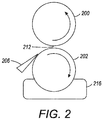
- Figure 2 shows an alternative arrangement of the liquid coating of the one rollers.
- one of the rollers 202 rotates through a liquid repository 216 and picks up a layer of the liquid.
- the doctor blade 206 smooths out the layer before it enters the nip between the rollers 202 and 200.
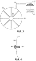
- a roller 300 receives centrally fed fluid through a coupling that allows the liquid to flow into a hollow center channel 302 of the typically cylindrical roller. Holes drilled into the rollers may form the hollow channel. Veins such as 304 that connect the channel to the surface of the roller allow the fluid to flow from the central channel to an array of holes on the surface of the roller. The holes penetrate the roller through to the veins.
- the centrally fed roller connects, typically through some sort of conduit 314 to a fluid reservoir 312.
- a controller 316 may regulate the pressure of the fluid being delivered to the central channel. Regulation of the pressure may also or instead involve geometric elements, discussed in more detail below.
- the conduit may consist of more than one individual conduit and the pressure in each may be controlled with different pressures.
- a side profile of a hole is shown in Figure 4 .
- the vein 304 traverses from the channel 302 of Figure 3 , and the hole penetrates to the surface of the roller 300. This allows the fluid to form surface droplets such as 306 shown in Figure 4 .
- the holes can have a range of holes and shapes allowing for different filament sizes. Using differently sized holes allows for formation of different sizes of surface droplets, that leads to differently sized filaments using one pressure in the channel, or the user of several pressures with several sized holes may offer even more selectability.
- the holes can have constant sizes and shapes throughout. Alternatively, they could result from a core having larger diameter holes and then encasing the core in another material. This would allow for smaller holes similar to a nozzle plate.
- the system may also allow for more complex recessed and protruded holes. Recessed holes have the advantage of higher sensitivity to backpressure and protruded holes may increase the ability of the roller to handle excess fluid.
- Figure 5 shows an embodiment of a recessed hole 308.
- the hole has a portion that lies lower than the surface of the roller. Control of the back pressure of the fluid in turn controls the size of the droplet that protrudes past the top of the channel into the recessed portion 308. As the pressure is increase, fluid bubble 306 protrudes further and further out from the surface. The thickness of this protrusion, effectively changes the amount of material that is pulled into a filament. By changing this backpressure, the amount of fluid protruding can be changed and the droplet size can be changed. This can be changed globally, if all the channels are connected to each other, but can also be changed on a channel by channel basis either through geometric constraints that narrow or widen the channel, which alter the pressure and drop size, or through being connected to a different pressure source.
- the portion of the recessed surface that receives fluid may be referred to here as the wetted portion. This may also achieve a negative film thickness.
- a negative film thickness as used here means that the droplet does not protrude from the surface as shown in the figure.
- this roller is used in the presence of a deformable roller as the other roller. Since the other roller is able to deform, even with a negative film thickness, the droplet will make contact with the other roller and it will continue to spray.
- the hole may have a protrusion 310 that causes the droplet 306 to form at an offset distance from the surface of the roller 300.
- the protruded hole can function similarly to the recessed hole. Different backpressures will cause different sized bubbles to protrude different amount and create different sized filaments and droplets.
- the protruded system provides for an area in which unused or excess fluid can be collected (the open area). This can be an advantage if not all material is sprayed, there are deviations in pressure control, or it is desirable to clean the fluid off during every revolution. In this case, the excess fluid will collect in the open area.
- the corner of the protrusion will be a highly desirable place to pin the fluid droplet. A large amount of pressure will be required for the fluid to wet a larger area and round that corner. This highly stable pinning point provides for a more stable pressure control since it will not be as sensitive to small changes in pressure.
- Figure 7 shows an embodiment of the central fed roller in a filament extension atomizer.
- the roller 300 receives fluid through the hollow central channel and then as the roller rotates, the liquid reaches the surface of the roller. As the surface of the roller enters the nip 402 between the rollers 300 and 400, the liquid contacts the roller 400. It then stretches between the two rollers as the rotate away from each other, forming the filaments and bursting into the spray of droplets.
- the surface 307 of the roller has an array of holes such as 306 shown in Figure 8
- these systems can employ liquids with a higher surface tension than would otherwise work with a doctor blade or a spinning surface.
- a system can provide a spray of droplets using these fluids.
Landscapes
- Chemical & Material Sciences (AREA)
- Organic Chemistry (AREA)
- Dispersion Chemistry (AREA)
- Chemical Kinetics & Catalysis (AREA)
- Nozzles (AREA)
- Treatment Of Fiber Materials (AREA)
Claims (5)
- Système d'atomisation comprenant :un réservoir de fluide (312) ;une paire de rouleaux (300, 400) ;une ligne de contact (402) formée entre les deux rouleaux ; etune surface de réception positionnée pour recevoir des gouttelettes formées lorsque du fluide sort des trous, s'étire entre les rouleaux à mesure qu'ils tournent dans des sens inverses pour former des filaments et que les filaments se divisent en gouttelettes ;caractérisé en ce qu'au moins l'un des rouleaux comporte :un canal d'alimentation central (302), le canal étant en communication fluidique avec le réservoir de fluide ;un réseau de trous sur une surface du rouleau ; etdes veines (304) reliant les canaux aux trous.
- Système d'atomisation selon la revendication 1, comprenant en outre un régulateur de pression pour régler une pression du fluide afin de maîtriser la taille des gouttelettes.
- Système d'atomisation selon la revendication 1, comprenant en outre de multiples canaux d'alimentation, en communication fluidique avec le canal d'alimentation central, dans lequel chaque canal d'alimentation est soumis à une pression de fluide différente.
- Procédé de génération de gouttelettes, comprenant les étapes suivantes :fournir un fluide à un premier rouleau (300) comportant un canal d'alimentation central (302), des veines (304) entre le canal d'alimentation central et une surface du rouleau, la surface du rouleau présentant des trous pour former des gouttelettes de surface, dans lequel les veines permettent au fluide de s'écouler du canal central vers les trous à la surface du rouleau ; etmettre le premier rouleau au contact d'un second rouleau (400), le second rouleau devant détacher le fluide du premier rouleau pour former un filament, et étirant le filament pour former des gouttelettes.
- Procédé selon la revendication 4, comprenant en outre la régulation d'une contre-pression du fluide pour maîtriser la taille des gouttelettes de surface.
Applications Claiming Priority (1)
| Application Number | Priority Date | Filing Date | Title |
|---|---|---|---|
| US15/651,195 US10493483B2 (en) | 2017-07-17 | 2017-07-17 | Central fed roller for filament extension atomizer |
Publications (2)
| Publication Number | Publication Date |
|---|---|
| EP3431190A1 EP3431190A1 (fr) | 2019-01-23 |
| EP3431190B1 true EP3431190B1 (fr) | 2020-06-17 |
Family
ID=62846064
Family Applications (1)
| Application Number | Title | Priority Date | Filing Date |
|---|---|---|---|
| EP18181461.7A Active EP3431190B1 (fr) | 2017-07-17 | 2018-07-03 | Rouleau a alimentation centrale pour atomiseur d'extension de filament |
Country Status (6)
| Country | Link |
|---|---|
| US (1) | US10493483B2 (fr) |
| EP (1) | EP3431190B1 (fr) |
| JP (1) | JP7037444B2 (fr) |
| KR (1) | KR20190008808A (fr) |
| CN (1) | CN109261426B (fr) |
| TW (1) | TWI749239B (fr) |
Families Citing this family (3)
| Publication number | Priority date | Publication date | Assignee | Title |
|---|---|---|---|---|
| US10953425B2 (en) * | 2018-04-25 | 2021-03-23 | Palo Alto Research Center Incorporated | Methods and systems for collecting droplets of strain hardening viscoelastic fluids in a spray |
| US20220115167A1 (en) | 2019-02-08 | 2022-04-14 | Sumitomo Electric Industries, Ltd. | Superconducting wire and permanent current switch |
| US11909052B2 (en) | 2021-06-30 | 2024-02-20 | Xerox Corporation | Fabrication of membrane electrode assembly with filament extension atomizer spray |
Family Cites Families (122)
| Publication number | Priority date | Publication date | Assignee | Title |
|---|---|---|---|---|
| US2291046A (en) | 1942-07-28 | Arrangement for burning liquid fuel | ||
| US2296861A (en) | 1940-08-08 | 1942-09-29 | Edward B Fallon | Glue applicator |
| US2551582A (en) | 1943-08-27 | 1951-05-08 | Chester F Carlson | Method of printing and developing solvent images |
| FR1035235A (fr) | 1951-04-09 | 1953-08-19 | Rodanet & Cie Ets | Perfectionnements aux rouleaux à peindre, à alimentation automatique et à main |
| US3052213A (en) | 1958-12-17 | 1962-09-04 | Ibm | Electrostatic printer apparatus for printing with liquid ink |
| DE1302344B (fr) | 1961-02-06 | |||
| BE616914A (fr) | 1961-04-26 | |||
| CH413018A (de) | 1963-04-30 | 1966-05-15 | Du Pont | Thermoelektrischer Generator |
| DE1577628A1 (de) | 1966-03-18 | 1970-03-05 | Agfa Gevaert Ag | Vorrichtung fuer die elektrostatische Zerstaeubung von Fluessigkeiten |
| US3926114A (en) | 1967-06-30 | 1975-12-16 | Walter E S Matuschke | Rotary lithographic printing press with ink and dampening fluid separator |
| US3702258A (en) | 1969-03-05 | 1972-11-07 | Eastman Kodak Co | Web treatment method |
| US3640203A (en) | 1969-06-09 | 1972-02-08 | Addressograph Multigraph | Liquid developing apparatus |
| US3977323A (en) | 1971-12-17 | 1976-08-31 | Electroprint, Inc. | Electrostatic printing system and method using ions and liquid aerosol toners |
| US3649829A (en) | 1970-10-06 | 1972-03-14 | Atomic Energy Commission | Laminar flow cell |
| US3779166A (en) | 1970-12-28 | 1973-12-18 | Electroprint Inc | Electrostatic printing system and method using ions and toner particles |
| US3717875A (en) | 1971-05-04 | 1973-02-20 | Little Inc A | Method and apparatus for directing the flow of liquid droplets in a stream and instruments incorporating the same |
| US3797926A (en) | 1971-08-27 | 1974-03-19 | Horizons Inc | Imaging system employing ions |
| US3988986A (en) | 1972-04-10 | 1976-11-02 | Peter Zimmer | Anti-drooling device for screen-printing machine |
| GB1492962A (en) | 1974-02-19 | 1977-11-23 | Alcan Res & Dev | Method and apparatus for applying coating compositions to strip material |
| US3873025A (en) | 1974-05-06 | 1975-03-25 | Stora Kopparbergs Bergslags Ab | Method and apparatus for atomizing a liquid medium and for spraying the atomized liquid medium in a predetermined direction |
| JPS5345109Y2 (fr) * | 1975-03-26 | 1978-10-28 | ||
| US4034670A (en) | 1975-03-24 | 1977-07-12 | Rockwell International Corporation | Dampening device for lithographic printing press |
| US4169427A (en) * | 1976-04-14 | 1979-10-02 | Crump Desmond G | Cable cleaning unit |
| US4217062A (en) * | 1978-02-27 | 1980-08-12 | Mile Lipovac | Paint feeding apparatus in combination with a fountain type paint roller |
| US4332281A (en) | 1978-03-10 | 1982-06-01 | Asahi Glass Company, Ltd. | Method and apparatus for spreading a polyurethane foamable composition |
| US4222059A (en) | 1978-12-18 | 1980-09-09 | Xerox Corporation | Ink jet multiple field electrostatic lens |
| US4384296A (en) | 1981-04-24 | 1983-05-17 | Xerox Corporation | Linear ink jet deflection method and apparatus |
| US4860652A (en) | 1986-05-24 | 1989-08-29 | Kabushikigaisha Tokyo Kikai Seisakusho | Mesh roller for planography |
| DE68909319T2 (de) | 1988-06-16 | 1994-02-03 | Dow Chemical Co | Verfahren für das Laminieren von Schichten. |
| DE3822692C2 (de) | 1988-07-05 | 1996-02-15 | Kochsmeier Hans Hermann | Rasterwalze in einem Auftragswerk einer Druckmaschine |
| CA2006227C (fr) | 1989-04-27 | 1995-07-18 | Goss Graphic Systems, Inc. | Rouleaux encreurs a micropores, hydrophobes et oleophiles |
| US5127325A (en) | 1989-04-27 | 1992-07-07 | Rockwell International Corporation | Hydrophobic and oleophilic microporous inking rollers |
| ATE91638T1 (de) | 1989-09-25 | 1993-08-15 | Schneider Usa Inc | Mehrschichtextrusion als verfahren zur herstellung von ballons zur gefaessplastik. |
| US5103763A (en) | 1989-12-08 | 1992-04-14 | International Business Machines Corporation | Apparatus for formation and electrostatic deposition of charged droplets |
| US5204697A (en) | 1990-09-04 | 1993-04-20 | Xerox Corporation | Ionographic functional color printer based on Traveling Cloud Development |
| DE4036661C1 (fr) | 1990-11-17 | 1992-06-17 | Man Roland Druckmaschinen Ag, 6050 Offenbach, De | |
| US5207158A (en) | 1991-02-19 | 1993-05-04 | Rockwell International | Long lived, variable-delivery ink metering method, system and roller for keyless lithography |
| US5216952A (en) | 1991-06-07 | 1993-06-08 | Heidelberg Harris Gmbh | Brush-type dampening unit in a rotary printing machine |
| GB9200936D0 (en) | 1992-01-16 | 1992-03-11 | Sprayforming Dev Ltd | Improvements in the processing of metals and alloys |
| US5314119A (en) | 1992-04-20 | 1994-05-24 | Latanick Equipment, Inc. | Method and apparatus for applying thin coatings of fluid droplets |
| US5326598A (en) | 1992-10-02 | 1994-07-05 | Minnesota Mining And Manufacturing Company | Electrospray coating apparatus and process utilizing precise control of filament and mist generation |
| US5332472A (en) | 1992-11-30 | 1994-07-26 | Philip Morris Incorporated | Application of fluidized material to a substrate using displacement transfer |
| US5609919A (en) | 1994-04-21 | 1997-03-11 | Altamat Inc. | Method for producing droplets |
| US5816161A (en) | 1994-07-22 | 1998-10-06 | Man Roland Druckmaschinen Ag | Erasable printing plate having a smooth pore free metallic surface |
| US5746844A (en) | 1995-09-08 | 1998-05-05 | Aeroquip Corporation | Method and apparatus for creating a free-form three-dimensional article using a layer-by-layer deposition of molten metal and using a stress-reducing annealing process on the deposited metal |
| JP3102843B2 (ja) | 1995-12-08 | 2000-10-23 | シャープ株式会社 | 画像記録装置 |
| US6399143B1 (en) | 1996-04-09 | 2002-06-04 | Delsys Pharmaceutical Corporation | Method for clamping and electrostatically coating a substrate |
| JP3972220B2 (ja) | 1997-07-25 | 2007-09-05 | ノードソン株式会社 | 接着剤のロール転写塗布方法 |
| US6506438B2 (en) | 1998-12-15 | 2003-01-14 | E Ink Corporation | Method for printing of transistor arrays on plastic substrates |
| EP1265713B1 (fr) | 1999-11-26 | 2004-02-25 | JohnsonDiversey, Inc. | Applicateur servant a appliquer un fluide sur une surface et procede d'application d'un fluide sur une surface |
| JP3400764B2 (ja) | 2000-01-27 | 2003-04-28 | 株式会社東京機械製作所 | インキング装置 |
| US6622335B1 (en) | 2000-03-29 | 2003-09-23 | Lam Research Corporation | Drip manifold for uniform chemical delivery |
| US6576861B2 (en) | 2000-07-25 | 2003-06-10 | The Research Foundation Of State University Of New York | Method and apparatus for fine feature spray deposition |
| US6660326B2 (en) | 2000-08-04 | 2003-12-09 | Tomoegawa Paper Co. Ltd. | Production method for monolayer powder film and production apparatus therefor |
| DE10108717C1 (de) | 2001-02-23 | 2002-07-11 | Bosch Gmbh Robert | Vorrichtung und Verfahren zur Entladung von dielektrischen Oberflächen |
| DE10131369A1 (de) | 2001-06-28 | 2003-01-09 | Sms Demag Ag | Verfahren und Vorrichtung zum Kühlen und Schmieren von Walzen eines Walzgerüstes |
| US6936105B2 (en) | 2002-03-28 | 2005-08-30 | Goss Contiweb B.V. | Applicator roller having a roller jacket, applicator roller and rotating element assembly, dryer, cooling roller stand and printing press having the applicator roller and method for coating a material web |
| US6866370B2 (en) | 2002-05-28 | 2005-03-15 | Eastman Kodak Company | Apparatus and method for improving gas flow uniformity in a continuous stream ink jet printer |
| AU2003238814A1 (en) | 2002-05-29 | 2003-12-19 | John I. Stofko | Adhesive compositions for bonding lignocellulosic materials, bonding methods and apparatus, and bonded articles |
| US7066088B2 (en) | 2002-07-31 | 2006-06-27 | Day International, Inc. | Variable cut-off offset press system and method of operation |
| US20070194157A1 (en) | 2002-08-06 | 2007-08-23 | Clean Earth Technologies, Llc | Method and apparatus for high transfer efficiency electrostatic spray |
| US20040050701A1 (en) | 2002-09-13 | 2004-03-18 | Mcentee John Francis | Electrostatically guiding ionized droplets in chemical array fabrication |
| EP1545797A2 (fr) | 2002-09-25 | 2005-06-29 | Koninklijke Philips Electronics N.V. | Procede de depot electrostatique |
| USRE40722E1 (en) | 2002-09-27 | 2009-06-09 | Surmodics, Inc. | Method and apparatus for coating of substrates |
| JP4917741B2 (ja) * | 2003-05-01 | 2012-04-18 | ノードソン コーポレーション | 電極インクの塗布及び乾燥方法 |
| KR100519343B1 (ko) | 2003-07-02 | 2005-10-07 | 엘지전자 주식회사 | 기능성 의복 |
| US7445738B2 (en) | 2003-09-18 | 2008-11-04 | United States Gypsum Company | Multi-layer process and apparatus for producing high strength fiber-reinforced structural cementitious panels |
| US7083830B2 (en) | 2003-10-02 | 2006-08-01 | E. I. Dupont De Nemours And Company | Electrostatically-assisted high-speed rotary application process for the production of special effect base coat/clear coat two-layer coatings |
| EP1625893A1 (fr) | 2004-08-10 | 2006-02-15 | Konica Minolta Photo Imaging, Inc. | Méthode de revêtement par pulvérisation, pulvérisateur et feuille pour enregistrement au jet d'encre. |
| US7641325B2 (en) | 2004-10-04 | 2010-01-05 | Kodak Graphic Communications Group Canada | Non-conductive fluid droplet characterizing apparatus and method |
| US7938341B2 (en) | 2004-12-13 | 2011-05-10 | Optomec Design Company | Miniature aerosol jet and aerosol jet array |
| US7611582B2 (en) | 2005-02-25 | 2009-11-03 | The Procter & Gamble Company | Apparatus and method for the transfer of a fluid to a moving web material |
| DE102005022308B4 (de) | 2005-05-13 | 2007-03-22 | Eos Gmbh Electro Optical Systems | Vorrichtung und Verfahren zum Herstellen eines dreidimensionalen Objekts mit einem beheizten Beschichter für pulverförmiges Aufbaumaterial |
| FR2890596B1 (fr) | 2005-09-13 | 2007-10-26 | Imaje Sa Sa | Dispositif de charge et deflexion de gouttes pour impression a jet d'encre |
| DE102005057109A1 (de) | 2005-11-26 | 2007-05-31 | Kunze-Concewitz, Horst, Dipl.-Phys. | Vorrichtung und Verfahren für mechanisches Prozessieren flacher, dünner Substrate im Durchlaufverfahren |
| DE102006045060A1 (de) | 2006-09-21 | 2008-04-10 | Kba-Metronic Ag | Verfahren und Vorrichtung zur Erzeugung von Tintentropfen mit variablen Tropfenvolumen |
| US8012586B2 (en) | 2006-11-22 | 2011-09-06 | Entegris, Inc. | Diamond like carbon coating of substrate housings |
| FR2909031B1 (fr) | 2006-11-24 | 2011-03-04 | Goss Int Montataire Sa | Machine d'impression et procede correspondant. |
| JP2008227178A (ja) | 2007-03-13 | 2008-09-25 | Sumitomo Chemical Co Ltd | 熱電変換モジュール用基板及び熱電変換モジュール |
| TWI338390B (en) | 2007-07-12 | 2011-03-01 | Ind Tech Res Inst | Flexible thermoelectric device and manufacturing method thereof |
| DE102007034877A1 (de) | 2007-07-24 | 2009-01-29 | Schmid Rhyner Ag | Verfahren und Vorrichtung zum Auftrag von Kunststoffbeschichtungen |
| TWI482662B (zh) | 2007-08-30 | 2015-05-01 | Optomec Inc | 機械上一體式及緊密式耦合之列印頭以及噴霧源 |
| US8273286B2 (en) | 2007-09-10 | 2012-09-25 | Fram Jerry R | Positive pressure shear impregnator and wetout |
| US20090155732A1 (en) | 2007-12-13 | 2009-06-18 | Palo Alto Research Center Incorporated | Method for Patterning Using Phase-Change Material |
| TW200933940A (en) | 2007-12-28 | 2009-08-01 | Basf Se | Extrusion process for preparing improved thermoelectric materials |
| EP2242651A2 (fr) | 2008-02-12 | 2010-10-27 | Heidelberger Druckmaschinen AG | Rotative d'impression à plat |
| TWI500364B (zh) | 2008-03-05 | 2015-09-11 | 美國伊利諾大學理事會 | 可延展且可折疊的電子裝置 |
| EP2131406A1 (fr) | 2008-06-02 | 2009-12-09 | Nederlandse Organisatie voor toegepast- natuurwetenschappelijk onderzoek TNO | Procédé de fabrication d'un générateur thermoélectrique, générateur thermoélectrique portable et vêtement le comportant |
| EP2285576B1 (fr) | 2008-06-05 | 2019-05-22 | Hewlett-Packard Development Company, L.P. | Réduction de gouttelettes d'encre générées par l'éclatement de bulles dans un révélateur d'encre |
| WO2010065270A2 (fr) | 2008-11-25 | 2010-06-10 | 3M Innovative Properties Company | Dispositif et procédé pour nettoyer des bandes flexibles |
| US9346021B2 (en) | 2008-12-02 | 2016-05-24 | Membrane Distillation Desalination Ltd., Co. | Composite membranes for membrane distillation and related methods of manufacture |
| US9163883B2 (en) | 2009-03-06 | 2015-10-20 | Kevlin Thermal Technologies, Inc. | Flexible thermal ground plane and manufacturing the same |
| ES2523349T3 (es) | 2009-07-14 | 2014-11-25 | Felix Böttcher Gmbh & Co. Kg | Rodillos de mecanismo de humectación |
| JP5573046B2 (ja) | 2009-08-24 | 2014-08-20 | 富士通株式会社 | 成膜装置及び成膜方法 |
| US9226476B2 (en) | 2009-11-23 | 2016-01-05 | Burlington Welding, Llc | Portable corral |
| US20110150036A1 (en) | 2009-12-21 | 2011-06-23 | Electronics And Telecommunications Research Institute | Flexible thermoelectric generator, wireless sensor node including the same and method of manufacturing the same |
| JP5830225B2 (ja) | 2010-01-08 | 2015-12-09 | ユニ・チャーム株式会社 | 流体吐出装置 |
| US20120103213A1 (en) | 2010-10-29 | 2012-05-03 | Palo Alto Research Center Incorporated | Ink Rheology Control Subsystem for a Variable Data Lithography System |
| TW201223777A (en) | 2010-12-13 | 2012-06-16 | Metal Ind Res & Dev Ct | Roller-type micro-contact printing device and printing method thereof |
| US20120227778A1 (en) | 2011-03-11 | 2012-09-13 | Imec | Thermoelectric Textile |
| US8720370B2 (en) | 2011-04-07 | 2014-05-13 | Dynamic Micro System Semiconductor Equipment GmbH | Methods and apparatuses for roll-on coating |
| JP5656295B2 (ja) | 2011-04-22 | 2015-01-21 | パナソニックIpマネジメント株式会社 | 熱電変換モジュールとその製造方法 |
| US9021948B2 (en) | 2011-04-27 | 2015-05-05 | Xerox Corporation | Environmental control subsystem for a variable data lithographic apparatus |
| US9010909B2 (en) | 2011-09-16 | 2015-04-21 | Eastman Kodak Company | Continuous inkjet printing method |
| US20130087180A1 (en) | 2011-10-10 | 2013-04-11 | Perpetua Power Source Technologies, Inc. | Wearable thermoelectric generator system |
| US20140015901A1 (en) | 2012-07-12 | 2014-01-16 | Michael Alan Marcus | Large-particle inkjet discharged-area development printing |
| US9132645B2 (en) | 2012-11-29 | 2015-09-15 | Palo Alto Research Center Incorporated | Pulsating heat pipe spreader for ink jet printer |
| JP5735047B2 (ja) * | 2013-06-21 | 2015-06-17 | 株式会社エナテック | 塗布装置及び塗布方法 |
| KR101625714B1 (ko) | 2013-08-27 | 2016-05-30 | 엔젯 주식회사 | 정전기력을 이용하는 분무식 패터닝 장치 |
| US10016777B2 (en) * | 2013-10-29 | 2018-07-10 | Palo Alto Research Center Incorporated | Methods and systems for creating aerosols |
| US9962673B2 (en) | 2013-10-29 | 2018-05-08 | Palo Alto Research Center Incorporated | Methods and systems for creating aerosols |
| US9433957B2 (en) | 2014-01-08 | 2016-09-06 | United Technologies Corporation | Cold spray systems with in-situ powder manufacturing |
| US20150197063A1 (en) | 2014-01-12 | 2015-07-16 | Zohar SHINAR | Device, method, and system of three-dimensional printing |
| US9527056B2 (en) | 2014-05-27 | 2016-12-27 | Palo Alto Research Center Incorporated | Methods and systems for creating aerosols |
| US9707588B2 (en) | 2014-05-27 | 2017-07-18 | Palo Alto Research Center Incorporated | Methods and systems for creating aerosols |
| US9757747B2 (en) | 2014-05-27 | 2017-09-12 | Palo Alto Research Center Incorporated | Methods and systems for creating aerosols |
| US9694379B2 (en) * | 2014-05-30 | 2017-07-04 | The Procter & Gamble Company | Customizable apparatus and method for transporting and depositing fluids |
| US10994473B2 (en) | 2015-02-10 | 2021-05-04 | Optomec, Inc. | Fabrication of three dimensional structures by in-flight curing of aerosols |
| US10400119B2 (en) | 2015-05-07 | 2019-09-03 | Ehsan Toyserkani | Method and apparatus for aerosol-based three-dimensional (3D) printing of flexible graphene electronic devices |
| US9789499B2 (en) * | 2015-07-29 | 2017-10-17 | Palo Alto Research Center Incorporated | Filament extension atomizers |
| US9707577B2 (en) * | 2015-07-29 | 2017-07-18 | Palo Alto Research Center Incorporated | Filament extension atomizers |
| US10500784B2 (en) | 2016-01-20 | 2019-12-10 | Palo Alto Research Center Incorporated | Additive deposition system and method |
-
2017
- 2017-07-17 US US15/651,195 patent/US10493483B2/en active Active
-
2018
- 2018-06-19 TW TW107120920A patent/TWI749239B/zh active
- 2018-06-19 CN CN201810648893.9A patent/CN109261426B/zh active Active
- 2018-06-25 JP JP2018119606A patent/JP7037444B2/ja active Active
- 2018-06-26 KR KR1020180073091A patent/KR20190008808A/ko not_active Application Discontinuation
- 2018-07-03 EP EP18181461.7A patent/EP3431190B1/fr active Active
Non-Patent Citations (1)
| Title |
|---|
| None * |
Also Published As
| Publication number | Publication date |
|---|---|
| TWI749239B (zh) | 2021-12-11 |
| JP2019018199A (ja) | 2019-02-07 |
| KR20190008808A (ko) | 2019-01-25 |
| CN109261426B (zh) | 2021-10-22 |
| CN109261426A (zh) | 2019-01-25 |
| EP3431190A1 (fr) | 2019-01-23 |
| JP7037444B2 (ja) | 2022-03-16 |
| US10493483B2 (en) | 2019-12-03 |
| TW201908010A (zh) | 2019-03-01 |
| US20190015862A1 (en) | 2019-01-17 |
Similar Documents
| Publication | Publication Date | Title |
|---|---|---|
| EP3431190B1 (fr) | Rouleau a alimentation centrale pour atomiseur d'extension de filament | |
| US7798434B2 (en) | Multi-plate nozzle and method for dispensing random pattern of adhesive filaments | |
| US8550381B2 (en) | Nozzle for dispensing random pattern of adhesive filaments | |
| US6969012B2 (en) | Low pressure atomizer for difficult to disperse solutions | |
| US7997689B2 (en) | Droplet ejection device for a highly viscous liquid | |
| EP2406075B1 (fr) | Appareil d'atomisation et procede d'humidification de toile | |
| EP3674004B1 (fr) | Ensemble buse avec face auto-nettoyante | |
| US6602554B1 (en) | Liquid atomization method and system | |
| JP2010511808A (ja) | 交換可能な流れ制限器アレイを用いたエレクトロスプレー/エレクトロスピニングアレイ | |
| US9873131B2 (en) | Filament extension atomizers | |
| JP6875381B2 (ja) | 高速間欠バリアノズル | |
| US9493895B2 (en) | Device for treating a fiber web | |
| KR102402131B1 (ko) | 필라멘트 신장 분무기 | |
| US20100196620A1 (en) | Process for coating a belt, in particular the fabric of a paper machine | |
| EP2647760B1 (fr) | Dispositif pour traiter un voile de fibres | |
| JPH0724563B2 (ja) | 天ぷら衣液の均等配分装置 |
Legal Events
| Date | Code | Title | Description |
|---|---|---|---|
| PUAI | Public reference made under article 153(3) epc to a published international application that has entered the european phase |
Free format text: ORIGINAL CODE: 0009012 |
|
| STAA | Information on the status of an ep patent application or granted ep patent |
Free format text: STATUS: THE APPLICATION HAS BEEN PUBLISHED |
|
| AK | Designated contracting states |
Kind code of ref document: A1 Designated state(s): AL AT BE BG CH CY CZ DE DK EE ES FI FR GB GR HR HU IE IS IT LI LT LU LV MC MK MT NL NO PL PT RO RS SE SI SK SM TR |
|
| AX | Request for extension of the european patent |
Extension state: BA ME |
|
| STAA | Information on the status of an ep patent application or granted ep patent |
Free format text: STATUS: REQUEST FOR EXAMINATION WAS MADE |
|
| 17P | Request for examination filed |
Effective date: 20190723 |
|
| RBV | Designated contracting states (corrected) |
Designated state(s): AL AT BE BG CH CY CZ DE DK EE ES FI FR GB GR HR HU IE IS IT LI LT LU LV MC MK MT NL NO PL PT RO RS SE SI SK SM TR |
|
| RIC1 | Information provided on ipc code assigned before grant |
Ipc: B01J 13/00 20060101ALI20191128BHEP Ipc: B05B 17/04 20060101AFI20191128BHEP |
|
| GRAP | Despatch of communication of intention to grant a patent |
Free format text: ORIGINAL CODE: EPIDOSNIGR1 |
|
| STAA | Information on the status of an ep patent application or granted ep patent |
Free format text: STATUS: GRANT OF PATENT IS INTENDED |
|
| INTG | Intention to grant announced |
Effective date: 20200117 |
|
| GRAS | Grant fee paid |
Free format text: ORIGINAL CODE: EPIDOSNIGR3 |
|
| GRAA | (expected) grant |
Free format text: ORIGINAL CODE: 0009210 |
|
| STAA | Information on the status of an ep patent application or granted ep patent |
Free format text: STATUS: THE PATENT HAS BEEN GRANTED |
|
| AK | Designated contracting states |
Kind code of ref document: B1 Designated state(s): AL AT BE BG CH CY CZ DE DK EE ES FI FR GB GR HR HU IE IS IT LI LT LU LV MC MK MT NL NO PL PT RO RS SE SI SK SM TR |
|
| REG | Reference to a national code |
Ref country code: GB Ref legal event code: FG4D |
|
| REG | Reference to a national code |
Ref country code: CH Ref legal event code: EP |
|
| REG | Reference to a national code |
Ref country code: DE Ref legal event code: R096 Ref document number: 602018005297 Country of ref document: DE |
|
| REG | Reference to a national code |
Ref country code: IE Ref legal event code: FG4D |
|
| REG | Reference to a national code |
Ref country code: AT Ref legal event code: REF Ref document number: 1280681 Country of ref document: AT Kind code of ref document: T Effective date: 20200715 |
|
| PG25 | Lapsed in a contracting state [announced via postgrant information from national office to epo] |
Ref country code: NO Free format text: LAPSE BECAUSE OF FAILURE TO SUBMIT A TRANSLATION OF THE DESCRIPTION OR TO PAY THE FEE WITHIN THE PRESCRIBED TIME-LIMIT Effective date: 20200917 Ref country code: GR Free format text: LAPSE BECAUSE OF FAILURE TO SUBMIT A TRANSLATION OF THE DESCRIPTION OR TO PAY THE FEE WITHIN THE PRESCRIBED TIME-LIMIT Effective date: 20200918 Ref country code: SE Free format text: LAPSE BECAUSE OF FAILURE TO SUBMIT A TRANSLATION OF THE DESCRIPTION OR TO PAY THE FEE WITHIN THE PRESCRIBED TIME-LIMIT Effective date: 20200617 Ref country code: FI Free format text: LAPSE BECAUSE OF FAILURE TO SUBMIT A TRANSLATION OF THE DESCRIPTION OR TO PAY THE FEE WITHIN THE PRESCRIBED TIME-LIMIT Effective date: 20200617 Ref country code: LT Free format text: LAPSE BECAUSE OF FAILURE TO SUBMIT A TRANSLATION OF THE DESCRIPTION OR TO PAY THE FEE WITHIN THE PRESCRIBED TIME-LIMIT Effective date: 20200617 |
|
| REG | Reference to a national code |
Ref country code: LT Ref legal event code: MG4D |
|
| REG | Reference to a national code |
Ref country code: NL Ref legal event code: MP Effective date: 20200617 |
|
| PG25 | Lapsed in a contracting state [announced via postgrant information from national office to epo] |
Ref country code: HR Free format text: LAPSE BECAUSE OF FAILURE TO SUBMIT A TRANSLATION OF THE DESCRIPTION OR TO PAY THE FEE WITHIN THE PRESCRIBED TIME-LIMIT Effective date: 20200617 Ref country code: BG Free format text: LAPSE BECAUSE OF FAILURE TO SUBMIT A TRANSLATION OF THE DESCRIPTION OR TO PAY THE FEE WITHIN THE PRESCRIBED TIME-LIMIT Effective date: 20200917 Ref country code: LV Free format text: LAPSE BECAUSE OF FAILURE TO SUBMIT A TRANSLATION OF THE DESCRIPTION OR TO PAY THE FEE WITHIN THE PRESCRIBED TIME-LIMIT Effective date: 20200617 Ref country code: RS Free format text: LAPSE BECAUSE OF FAILURE TO SUBMIT A TRANSLATION OF THE DESCRIPTION OR TO PAY THE FEE WITHIN THE PRESCRIBED TIME-LIMIT Effective date: 20200617 |
|
| REG | Reference to a national code |
Ref country code: AT Ref legal event code: MK05 Ref document number: 1280681 Country of ref document: AT Kind code of ref document: T Effective date: 20200617 |
|
| PG25 | Lapsed in a contracting state [announced via postgrant information from national office to epo] |
Ref country code: AL Free format text: LAPSE BECAUSE OF FAILURE TO SUBMIT A TRANSLATION OF THE DESCRIPTION OR TO PAY THE FEE WITHIN THE PRESCRIBED TIME-LIMIT Effective date: 20200617 Ref country code: NL Free format text: LAPSE BECAUSE OF FAILURE TO SUBMIT A TRANSLATION OF THE DESCRIPTION OR TO PAY THE FEE WITHIN THE PRESCRIBED TIME-LIMIT Effective date: 20200617 |
|
| PG25 | Lapsed in a contracting state [announced via postgrant information from national office to epo] |
Ref country code: PT Free format text: LAPSE BECAUSE OF FAILURE TO SUBMIT A TRANSLATION OF THE DESCRIPTION OR TO PAY THE FEE WITHIN THE PRESCRIBED TIME-LIMIT Effective date: 20201019 Ref country code: AT Free format text: LAPSE BECAUSE OF FAILURE TO SUBMIT A TRANSLATION OF THE DESCRIPTION OR TO PAY THE FEE WITHIN THE PRESCRIBED TIME-LIMIT Effective date: 20200617 Ref country code: IT Free format text: LAPSE BECAUSE OF FAILURE TO SUBMIT A TRANSLATION OF THE DESCRIPTION OR TO PAY THE FEE WITHIN THE PRESCRIBED TIME-LIMIT Effective date: 20200617 Ref country code: EE Free format text: LAPSE BECAUSE OF FAILURE TO SUBMIT A TRANSLATION OF THE DESCRIPTION OR TO PAY THE FEE WITHIN THE PRESCRIBED TIME-LIMIT Effective date: 20200617 Ref country code: SM Free format text: LAPSE BECAUSE OF FAILURE TO SUBMIT A TRANSLATION OF THE DESCRIPTION OR TO PAY THE FEE WITHIN THE PRESCRIBED TIME-LIMIT Effective date: 20200617 Ref country code: RO Free format text: LAPSE BECAUSE OF FAILURE TO SUBMIT A TRANSLATION OF THE DESCRIPTION OR TO PAY THE FEE WITHIN THE PRESCRIBED TIME-LIMIT Effective date: 20200617 Ref country code: CZ Free format text: LAPSE BECAUSE OF FAILURE TO SUBMIT A TRANSLATION OF THE DESCRIPTION OR TO PAY THE FEE WITHIN THE PRESCRIBED TIME-LIMIT Effective date: 20200617 Ref country code: ES Free format text: LAPSE BECAUSE OF FAILURE TO SUBMIT A TRANSLATION OF THE DESCRIPTION OR TO PAY THE FEE WITHIN THE PRESCRIBED TIME-LIMIT Effective date: 20200617 |
|
| PG25 | Lapsed in a contracting state [announced via postgrant information from national office to epo] |
Ref country code: SK Free format text: LAPSE BECAUSE OF FAILURE TO SUBMIT A TRANSLATION OF THE DESCRIPTION OR TO PAY THE FEE WITHIN THE PRESCRIBED TIME-LIMIT Effective date: 20200617 Ref country code: PL Free format text: LAPSE BECAUSE OF FAILURE TO SUBMIT A TRANSLATION OF THE DESCRIPTION OR TO PAY THE FEE WITHIN THE PRESCRIBED TIME-LIMIT Effective date: 20200617 Ref country code: IS Free format text: LAPSE BECAUSE OF FAILURE TO SUBMIT A TRANSLATION OF THE DESCRIPTION OR TO PAY THE FEE WITHIN THE PRESCRIBED TIME-LIMIT Effective date: 20201017 |
|
| REG | Reference to a national code |
Ref country code: DE Ref legal event code: R097 Ref document number: 602018005297 Country of ref document: DE |
|
| PG25 | Lapsed in a contracting state [announced via postgrant information from national office to epo] |
Ref country code: MC Free format text: LAPSE BECAUSE OF FAILURE TO SUBMIT A TRANSLATION OF THE DESCRIPTION OR TO PAY THE FEE WITHIN THE PRESCRIBED TIME-LIMIT Effective date: 20200617 |
|
| PLBE | No opposition filed within time limit |
Free format text: ORIGINAL CODE: 0009261 |
|
| STAA | Information on the status of an ep patent application or granted ep patent |
Free format text: STATUS: NO OPPOSITION FILED WITHIN TIME LIMIT |
|
| REG | Reference to a national code |
Ref country code: BE Ref legal event code: MM Effective date: 20200731 |
|
| PG25 | Lapsed in a contracting state [announced via postgrant information from national office to epo] |
Ref country code: IE Free format text: LAPSE BECAUSE OF NON-PAYMENT OF DUE FEES Effective date: 20200703 Ref country code: LU Free format text: LAPSE BECAUSE OF NON-PAYMENT OF DUE FEES Effective date: 20200703 Ref country code: DK Free format text: LAPSE BECAUSE OF FAILURE TO SUBMIT A TRANSLATION OF THE DESCRIPTION OR TO PAY THE FEE WITHIN THE PRESCRIBED TIME-LIMIT Effective date: 20200617 |
|
| 26N | No opposition filed |
Effective date: 20210318 |
|
| PG25 | Lapsed in a contracting state [announced via postgrant information from national office to epo] |
Ref country code: BE Free format text: LAPSE BECAUSE OF NON-PAYMENT OF DUE FEES Effective date: 20200731 Ref country code: SI Free format text: LAPSE BECAUSE OF FAILURE TO SUBMIT A TRANSLATION OF THE DESCRIPTION OR TO PAY THE FEE WITHIN THE PRESCRIBED TIME-LIMIT Effective date: 20200617 |
|
| REG | Reference to a national code |
Ref country code: CH Ref legal event code: PL |
|
| PG25 | Lapsed in a contracting state [announced via postgrant information from national office to epo] |
Ref country code: LI Free format text: LAPSE BECAUSE OF NON-PAYMENT OF DUE FEES Effective date: 20210731 Ref country code: CH Free format text: LAPSE BECAUSE OF NON-PAYMENT OF DUE FEES Effective date: 20210731 |
|
| PG25 | Lapsed in a contracting state [announced via postgrant information from national office to epo] |
Ref country code: TR Free format text: LAPSE BECAUSE OF FAILURE TO SUBMIT A TRANSLATION OF THE DESCRIPTION OR TO PAY THE FEE WITHIN THE PRESCRIBED TIME-LIMIT Effective date: 20200617 Ref country code: MT Free format text: LAPSE BECAUSE OF FAILURE TO SUBMIT A TRANSLATION OF THE DESCRIPTION OR TO PAY THE FEE WITHIN THE PRESCRIBED TIME-LIMIT Effective date: 20200617 Ref country code: CY Free format text: LAPSE BECAUSE OF FAILURE TO SUBMIT A TRANSLATION OF THE DESCRIPTION OR TO PAY THE FEE WITHIN THE PRESCRIBED TIME-LIMIT Effective date: 20200617 |
|
| PG25 | Lapsed in a contracting state [announced via postgrant information from national office to epo] |
Ref country code: MK Free format text: LAPSE BECAUSE OF FAILURE TO SUBMIT A TRANSLATION OF THE DESCRIPTION OR TO PAY THE FEE WITHIN THE PRESCRIBED TIME-LIMIT Effective date: 20200617 |
|
| PGFP | Annual fee paid to national office [announced via postgrant information from national office to epo] |
Ref country code: GB Payment date: 20230720 Year of fee payment: 6 |
|
| PGFP | Annual fee paid to national office [announced via postgrant information from national office to epo] |
Ref country code: FR Payment date: 20230720 Year of fee payment: 6 Ref country code: DE Payment date: 20230720 Year of fee payment: 6 |