EP3428643A1 - Substance-marking patch, and method and apparatus for tissue diagnosis using same - Google Patents
Substance-marking patch, and method and apparatus for tissue diagnosis using same Download PDFInfo
- Publication number
- EP3428643A1 EP3428643A1 EP17756843.3A EP17756843A EP3428643A1 EP 3428643 A1 EP3428643 A1 EP 3428643A1 EP 17756843 A EP17756843 A EP 17756843A EP 3428643 A1 EP3428643 A1 EP 3428643A1
- Authority
- EP
- European Patent Office
- Prior art keywords
- substance
- patch
- tissue sample
- target
- fluorescence
- Prior art date
- Legal status (The legal status is an assumption and is not a legal conclusion. Google has not performed a legal analysis and makes no representation as to the accuracy of the status listed.)
- Pending
Links
- 238000003745 diagnosis Methods 0.000 title claims abstract description 235
- 238000000034 method Methods 0.000 title claims description 151
- 239000000126 substance Substances 0.000 claims abstract description 1248
- 239000013076 target substance Substances 0.000 claims abstract description 296
- 238000006243 chemical reaction Methods 0.000 claims abstract description 236
- 238000002372 labelling Methods 0.000 claims abstract description 182
- 239000000523 sample Substances 0.000 claims description 507
- 239000007850 fluorescent dye Substances 0.000 claims description 171
- 238000001215 fluorescent labelling Methods 0.000 claims description 171
- 108090000623 proteins and genes Proteins 0.000 claims description 139
- 102000004169 proteins and genes Human genes 0.000 claims description 138
- 238000009826 distribution Methods 0.000 claims description 34
- 238000002073 fluorescence micrograph Methods 0.000 claims description 25
- 238000009739 binding Methods 0.000 claims description 24
- 230000027455 binding Effects 0.000 claims description 23
- WZUVPPKBWHMQCE-UHFFFAOYSA-N Haematoxylin Chemical compound C12=CC(O)=C(O)C=C2CC2(O)C1C1=CC=C(O)C(O)=C1OC2 WZUVPPKBWHMQCE-UHFFFAOYSA-N 0.000 claims description 22
- 108020004711 Nucleic Acid Probes Proteins 0.000 claims description 13
- 239000003550 marker Substances 0.000 claims description 13
- 239000002853 nucleic acid probe Substances 0.000 claims description 13
- 238000003384 imaging method Methods 0.000 claims description 7
- 238000005259 measurement Methods 0.000 claims description 7
- 230000001939 inductive effect Effects 0.000 claims description 2
- 210000001519 tissue Anatomy 0.000 description 556
- 239000007788 liquid Substances 0.000 description 187
- 238000010186 staining Methods 0.000 description 107
- 230000033001 locomotion Effects 0.000 description 68
- 238000010521 absorption reaction Methods 0.000 description 52
- 239000000654 additive Substances 0.000 description 47
- 230000000996 additive effect Effects 0.000 description 47
- 238000005406 washing Methods 0.000 description 40
- XLYOFNOQVPJJNP-UHFFFAOYSA-N water Substances O XLYOFNOQVPJJNP-UHFFFAOYSA-N 0.000 description 34
- 210000004027 cell Anatomy 0.000 description 30
- 239000000243 solution Substances 0.000 description 28
- 210000004940 nucleus Anatomy 0.000 description 24
- 230000008569 process Effects 0.000 description 21
- 238000001514 detection method Methods 0.000 description 20
- 102000004190 Enzymes Human genes 0.000 description 19
- 108090000790 Enzymes Proteins 0.000 description 19
- 206010028980 Neoplasm Diseases 0.000 description 19
- 230000008859 change Effects 0.000 description 18
- 230000001788 irregular Effects 0.000 description 18
- 239000002245 particle Substances 0.000 description 18
- 239000000758 substrate Substances 0.000 description 18
- 238000009792 diffusion process Methods 0.000 description 17
- 230000007613 environmental effect Effects 0.000 description 17
- 201000011510 cancer Diseases 0.000 description 16
- 239000003153 chemical reaction reagent Substances 0.000 description 16
- 239000000203 mixture Substances 0.000 description 16
- 230000000877 morphologic effect Effects 0.000 description 15
- FWBHETKCLVMNFS-UHFFFAOYSA-N 4',6-Diamino-2-phenylindol Chemical compound C1=CC(C(=N)N)=CC=C1C1=CC2=CC=C(C(N)=N)C=C2N1 FWBHETKCLVMNFS-UHFFFAOYSA-N 0.000 description 14
- 201000010099 disease Diseases 0.000 description 13
- 208000037265 diseases, disorders, signs and symptoms Diseases 0.000 description 13
- 230000000694 effects Effects 0.000 description 13
- 210000004881 tumor cell Anatomy 0.000 description 13
- 239000000427 antigen Substances 0.000 description 12
- 102000036639 antigens Human genes 0.000 description 12
- 108091007433 antigens Proteins 0.000 description 12
- 230000002209 hydrophobic effect Effects 0.000 description 12
- 238000012744 immunostaining Methods 0.000 description 11
- 239000012128 staining reagent Substances 0.000 description 11
- YQGOJNYOYNNSMM-UHFFFAOYSA-N eosin Chemical compound [Na+].OC(=O)C1=CC=CC=C1C1=C2C=C(Br)C(=O)C(Br)=C2OC2=C(Br)C(O)=C(Br)C=C21 YQGOJNYOYNNSMM-UHFFFAOYSA-N 0.000 description 10
- 239000007787 solid Substances 0.000 description 9
- 239000002904 solvent Substances 0.000 description 9
- 210000000805 cytoplasm Anatomy 0.000 description 8
- 238000002405 diagnostic procedure Methods 0.000 description 8
- 238000007901 in situ hybridization Methods 0.000 description 8
- 238000004519 manufacturing process Methods 0.000 description 8
- 230000009870 specific binding Effects 0.000 description 8
- 238000004458 analytical method Methods 0.000 description 7
- 238000007796 conventional method Methods 0.000 description 7
- 230000001900 immune effect Effects 0.000 description 7
- 238000001556 precipitation Methods 0.000 description 7
- 238000000926 separation method Methods 0.000 description 6
- 230000005465 channeling Effects 0.000 description 5
- 230000003247 decreasing effect Effects 0.000 description 5
- 238000011161 development Methods 0.000 description 5
- 230000018109 developmental process Effects 0.000 description 5
- 230000001747 exhibiting effect Effects 0.000 description 5
- 230000001965 increasing effect Effects 0.000 description 5
- 238000002965 ELISA Methods 0.000 description 4
- 238000013473 artificial intelligence Methods 0.000 description 4
- 238000012258 culturing Methods 0.000 description 4
- 239000002105 nanoparticle Substances 0.000 description 4
- CSCPPACGZOOCGX-UHFFFAOYSA-N Acetone Chemical compound CC(C)=O CSCPPACGZOOCGX-UHFFFAOYSA-N 0.000 description 3
- 108010077544 Chromatin Proteins 0.000 description 3
- 239000007853 buffer solution Substances 0.000 description 3
- 230000001413 cellular effect Effects 0.000 description 3
- 210000003483 chromatin Anatomy 0.000 description 3
- 239000003086 colorant Substances 0.000 description 3
- 239000000499 gel Substances 0.000 description 3
- 238000001764 infiltration Methods 0.000 description 3
- 230000008595 infiltration Effects 0.000 description 3
- 239000012188 paraffin wax Substances 0.000 description 3
- 238000002360 preparation method Methods 0.000 description 3
- 229920000936 Agarose Polymers 0.000 description 2
- IJGRMHOSHXDMSA-UHFFFAOYSA-N Atomic nitrogen Chemical compound N#N IJGRMHOSHXDMSA-UHFFFAOYSA-N 0.000 description 2
- 241000894006 Bacteria Species 0.000 description 2
- LFQSCWFLJHTTHZ-UHFFFAOYSA-N Ethanol Chemical compound CCO LFQSCWFLJHTTHZ-UHFFFAOYSA-N 0.000 description 2
- 102000029749 Microtubule Human genes 0.000 description 2
- 108091022875 Microtubule Proteins 0.000 description 2
- 108091028043 Nucleic acid sequence Proteins 0.000 description 2
- 230000009471 action Effects 0.000 description 2
- 239000000872 buffer Substances 0.000 description 2
- 229910052729 chemical element Inorganic materials 0.000 description 2
- 238000004140 cleaning Methods 0.000 description 2
- 230000000295 complement effect Effects 0.000 description 2
- 150000001875 compounds Chemical class 0.000 description 2
- 230000018044 dehydration Effects 0.000 description 2
- 238000006297 dehydration reaction Methods 0.000 description 2
- 230000004069 differentiation Effects 0.000 description 2
- LOKCTEFSRHRXRJ-UHFFFAOYSA-I dipotassium trisodium dihydrogen phosphate hydrogen phosphate dichloride Chemical compound P(=O)(O)(O)[O-].[K+].P(=O)(O)([O-])[O-].[Na+].[Na+].[Cl-].[K+].[Cl-].[Na+] LOKCTEFSRHRXRJ-UHFFFAOYSA-I 0.000 description 2
- 238000001035 drying Methods 0.000 description 2
- 238000002848 electrochemical method Methods 0.000 description 2
- 238000001704 evaporation Methods 0.000 description 2
- 230000008020 evaporation Effects 0.000 description 2
- 239000010419 fine particle Substances 0.000 description 2
- MHMNJMPURVTYEJ-UHFFFAOYSA-N fluorescein-5-isothiocyanate Chemical compound O1C(=O)C2=CC(N=C=S)=CC=C2C21C1=CC=C(O)C=C1OC1=CC(O)=CC=C21 MHMNJMPURVTYEJ-UHFFFAOYSA-N 0.000 description 2
- 238000001917 fluorescence detection Methods 0.000 description 2
- 239000007789 gas Substances 0.000 description 2
- 239000011521 glass Substances 0.000 description 2
- 238000010191 image analysis Methods 0.000 description 2
- 238000003018 immunoassay Methods 0.000 description 2
- 230000000984 immunochemical effect Effects 0.000 description 2
- 239000011159 matrix material Substances 0.000 description 2
- 210000004688 microtubule Anatomy 0.000 description 2
- 210000003463 organelle Anatomy 0.000 description 2
- 230000003204 osmotic effect Effects 0.000 description 2
- 239000002953 phosphate buffered saline Substances 0.000 description 2
- 238000012123 point-of-care testing Methods 0.000 description 2
- 239000011148 porous material Substances 0.000 description 2
- 239000000047 product Substances 0.000 description 2
- 239000007790 solid phase Substances 0.000 description 2
- 230000007704 transition Effects 0.000 description 2
- 239000003656 tris buffered saline Substances 0.000 description 2
- MPVDXIMFBOLMNW-ISLYRVAYSA-N 7-hydroxy-8-[(E)-phenyldiazenyl]naphthalene-1,3-disulfonic acid Chemical compound OC1=CC=C2C=C(S(O)(=O)=O)C=C(S(O)(=O)=O)C2=C1\N=N\C1=CC=CC=C1 MPVDXIMFBOLMNW-ISLYRVAYSA-N 0.000 description 1
- 206010006187 Breast cancer Diseases 0.000 description 1
- 208000026310 Breast neoplasm Diseases 0.000 description 1
- OKTJSMMVPCPJKN-UHFFFAOYSA-N Carbon Chemical compound [C] OKTJSMMVPCPJKN-UHFFFAOYSA-N 0.000 description 1
- 238000000116 DAPI staining Methods 0.000 description 1
- 108010010803 Gelatin Proteins 0.000 description 1
- 241000701806 Human papillomavirus Species 0.000 description 1
- 208000026350 Inborn Genetic disease Diseases 0.000 description 1
- 241001465754 Metazoa Species 0.000 description 1
- 229920001410 Microfiber Polymers 0.000 description 1
- 102000008934 Muscle Proteins Human genes 0.000 description 1
- 108010074084 Muscle Proteins Proteins 0.000 description 1
- 108700020796 Oncogene Proteins 0.000 description 1
- 239000004743 Polypropylene Substances 0.000 description 1
- 229920001213 Polysorbate 20 Polymers 0.000 description 1
- 239000004793 Polystyrene Substances 0.000 description 1
- OMOVVBIIQSXZSZ-UHFFFAOYSA-N [6-(4-acetyloxy-5,9a-dimethyl-2,7-dioxo-4,5a,6,9-tetrahydro-3h-pyrano[3,4-b]oxepin-5-yl)-5-formyloxy-3-(furan-3-yl)-3a-methyl-7-methylidene-1a,2,3,4,5,6-hexahydroindeno[1,7a-b]oxiren-4-yl] 2-hydroxy-3-methylpentanoate Chemical compound CC12C(OC(=O)C(O)C(C)CC)C(OC=O)C(C3(C)C(CC(=O)OC4(C)COC(=O)CC43)OC(C)=O)C(=C)C32OC3CC1C=1C=COC=1 OMOVVBIIQSXZSZ-UHFFFAOYSA-N 0.000 description 1
- RZUBARUFLYGOGC-MTHOTQAESA-L acid fuchsin Chemical compound [Na+].[Na+].[O-]S(=O)(=O)C1=C(N)C(C)=CC(C(=C\2C=C(C(=[NH2+])C=C/2)S([O-])(=O)=O)\C=2C=C(C(N)=CC=2)S([O-])(=O)=O)=C1 RZUBARUFLYGOGC-MTHOTQAESA-L 0.000 description 1
- 230000002378 acidificating effect Effects 0.000 description 1
- 230000032683 aging Effects 0.000 description 1
- 125000000129 anionic group Chemical group 0.000 description 1
- 230000004071 biological effect Effects 0.000 description 1
- 238000001574 biopsy Methods 0.000 description 1
- 210000001124 body fluid Anatomy 0.000 description 1
- 238000000339 bright-field microscopy Methods 0.000 description 1
- 230000003139 buffering effect Effects 0.000 description 1
- 229910052799 carbon Inorganic materials 0.000 description 1
- 125000002091 cationic group Chemical group 0.000 description 1
- 230000010261 cell growth Effects 0.000 description 1
- 239000003795 chemical substances by application Substances 0.000 description 1
- 239000000084 colloidal system Substances 0.000 description 1
- 238000009833 condensation Methods 0.000 description 1
- 230000005494 condensation Effects 0.000 description 1
- 238000012864 cross contamination Methods 0.000 description 1
- 238000005520 cutting process Methods 0.000 description 1
- 230000003111 delayed effect Effects 0.000 description 1
- 238000013461 design Methods 0.000 description 1
- 238000004090 dissolution Methods 0.000 description 1
- 238000013399 early diagnosis Methods 0.000 description 1
- 238000004049 embossing Methods 0.000 description 1
- 230000003511 endothelial effect Effects 0.000 description 1
- 238000005516 engineering process Methods 0.000 description 1
- 230000002327 eosinophilic effect Effects 0.000 description 1
- 210000000981 epithelium Anatomy 0.000 description 1
- 235000019441 ethanol Nutrition 0.000 description 1
- 238000012757 fluorescence staining Methods 0.000 description 1
- 230000008014 freezing Effects 0.000 description 1
- 238000007710 freezing Methods 0.000 description 1
- 239000008273 gelatin Substances 0.000 description 1
- 229920000159 gelatin Polymers 0.000 description 1
- 235000019322 gelatine Nutrition 0.000 description 1
- 235000011852 gelatine desserts Nutrition 0.000 description 1
- 208000016361 genetic disease Diseases 0.000 description 1
- 230000012010 growth Effects 0.000 description 1
- 239000003102 growth factor Substances 0.000 description 1
- 230000013632 homeostatic process Effects 0.000 description 1
- 238000000265 homogenisation Methods 0.000 description 1
- 238000010166 immunofluorescence Methods 0.000 description 1
- 230000006872 improvement Effects 0.000 description 1
- 238000000338 in vitro Methods 0.000 description 1
- 239000004615 ingredient Substances 0.000 description 1
- 239000003112 inhibitor Substances 0.000 description 1
- 239000003999 initiator Substances 0.000 description 1
- 229910052500 inorganic mineral Inorganic materials 0.000 description 1
- 150000002540 isothiocyanates Chemical class 0.000 description 1
- 230000003902 lesion Effects 0.000 description 1
- 239000007791 liquid phase Substances 0.000 description 1
- 230000003211 malignant effect Effects 0.000 description 1
- 238000007726 management method Methods 0.000 description 1
- 239000000463 material Substances 0.000 description 1
- 239000002184 metal Substances 0.000 description 1
- 229910044991 metal oxide Inorganic materials 0.000 description 1
- 150000004706 metal oxides Chemical class 0.000 description 1
- WSFSSNUMVMOOMR-NJFSPNSNSA-N methanone Chemical compound O=[14CH2] WSFSSNUMVMOOMR-NJFSPNSNSA-N 0.000 description 1
- CXKWCBBOMKCUKX-UHFFFAOYSA-M methylene blue Chemical compound [Cl-].C1=CC(N(C)C)=CC2=[S+]C3=CC(N(C)C)=CC=C3N=C21 CXKWCBBOMKCUKX-UHFFFAOYSA-M 0.000 description 1
- 229960000907 methylthioninium chloride Drugs 0.000 description 1
- 244000005700 microbiome Species 0.000 description 1
- 239000003658 microfiber Substances 0.000 description 1
- 239000011707 mineral Substances 0.000 description 1
- 230000004048 modification Effects 0.000 description 1
- 238000012986 modification Methods 0.000 description 1
- 210000000663 muscle cell Anatomy 0.000 description 1
- 229910052757 nitrogen Inorganic materials 0.000 description 1
- 235000015097 nutrients Nutrition 0.000 description 1
- 210000000056 organ Anatomy 0.000 description 1
- 230000001575 pathological effect Effects 0.000 description 1
- 239000012466 permeate Substances 0.000 description 1
- 239000000049 pigment Substances 0.000 description 1
- 229920001223 polyethylene glycol Polymers 0.000 description 1
- 235000010486 polyoxyethylene sorbitan monolaurate Nutrition 0.000 description 1
- 239000000256 polyoxyethylene sorbitan monolaurate Substances 0.000 description 1
- -1 polypropylene Polymers 0.000 description 1
- 229920001155 polypropylene Polymers 0.000 description 1
- 229920002223 polystyrene Polymers 0.000 description 1
- 239000000843 powder Substances 0.000 description 1
- 238000007781 pre-processing Methods 0.000 description 1
- 238000009598 prenatal testing Methods 0.000 description 1
- 238000012545 processing Methods 0.000 description 1
- 238000004445 quantitative analysis Methods 0.000 description 1
- 230000005855 radiation Effects 0.000 description 1
- 230000009467 reduction Effects 0.000 description 1
- 150000003839 salts Chemical class 0.000 description 1
- 239000004065 semiconductor Substances 0.000 description 1
- 210000002966 serum Anatomy 0.000 description 1
- 238000007447 staining method Methods 0.000 description 1
- 229950003937 tolonium Drugs 0.000 description 1
- HNONEKILPDHFOL-UHFFFAOYSA-M tolonium chloride Chemical compound [Cl-].C1=C(C)C(N)=CC2=[S+]C3=CC(N(C)C)=CC=C3N=C21 HNONEKILPDHFOL-UHFFFAOYSA-M 0.000 description 1
- 238000012546 transfer Methods 0.000 description 1
- 231100000588 tumorigenic Toxicity 0.000 description 1
- 230000000381 tumorigenic effect Effects 0.000 description 1
- 235000013343 vitamin Nutrition 0.000 description 1
- 239000011782 vitamin Substances 0.000 description 1
- 229940088594 vitamin Drugs 0.000 description 1
- 229930003231 vitamin Natural products 0.000 description 1
Images


Classifications
-
- C—CHEMISTRY; METALLURGY
- C12—BIOCHEMISTRY; BEER; SPIRITS; WINE; VINEGAR; MICROBIOLOGY; ENZYMOLOGY; MUTATION OR GENETIC ENGINEERING
- C12Q—MEASURING OR TESTING PROCESSES INVOLVING ENZYMES, NUCLEIC ACIDS OR MICROORGANISMS; COMPOSITIONS OR TEST PAPERS THEREFOR; PROCESSES OF PREPARING SUCH COMPOSITIONS; CONDITION-RESPONSIVE CONTROL IN MICROBIOLOGICAL OR ENZYMOLOGICAL PROCESSES
- C12Q1/00—Measuring or testing processes involving enzymes, nucleic acids or microorganisms; Compositions therefor; Processes of preparing such compositions
- C12Q1/02—Measuring or testing processes involving enzymes, nucleic acids or microorganisms; Compositions therefor; Processes of preparing such compositions involving viable microorganisms
- C12Q1/025—Measuring or testing processes involving enzymes, nucleic acids or microorganisms; Compositions therefor; Processes of preparing such compositions involving viable microorganisms for testing or evaluating the effect of chemical or biological compounds, e.g. drugs, cosmetics
-
- G—PHYSICS
- G01—MEASURING; TESTING
- G01N—INVESTIGATING OR ANALYSING MATERIALS BY DETERMINING THEIR CHEMICAL OR PHYSICAL PROPERTIES
- G01N33/00—Investigating or analysing materials by specific methods not covered by groups G01N1/00 - G01N31/00
- G01N33/48—Biological material, e.g. blood, urine; Haemocytometers
- G01N33/483—Physical analysis of biological material
- G01N33/4833—Physical analysis of biological material of solid biological material, e.g. tissue samples, cell cultures
-
- G—PHYSICS
- G01—MEASURING; TESTING
- G01N—INVESTIGATING OR ANALYSING MATERIALS BY DETERMINING THEIR CHEMICAL OR PHYSICAL PROPERTIES
- G01N1/00—Sampling; Preparing specimens for investigation
- G01N1/28—Preparing specimens for investigation including physical details of (bio-)chemical methods covered elsewhere, e.g. G01N33/50, C12Q
- G01N1/30—Staining; Impregnating ; Fixation; Dehydration; Multistep processes for preparing samples of tissue, cell or nucleic acid material and the like for analysis
- G01N1/31—Apparatus therefor
- G01N1/312—Apparatus therefor for samples mounted on planar substrates
-
- B—PERFORMING OPERATIONS; TRANSPORTING
- B01—PHYSICAL OR CHEMICAL PROCESSES OR APPARATUS IN GENERAL
- B01F—MIXING, e.g. DISSOLVING, EMULSIFYING OR DISPERSING
- B01F33/00—Other mixers; Mixing plants; Combinations of mixers
- B01F33/30—Micromixers
- B01F33/3039—Micromixers with mixing achieved by diffusion between layers
-
- B—PERFORMING OPERATIONS; TRANSPORTING
- B01—PHYSICAL OR CHEMICAL PROCESSES OR APPARATUS IN GENERAL
- B01L—CHEMICAL OR PHYSICAL LABORATORY APPARATUS FOR GENERAL USE
- B01L3/00—Containers or dishes for laboratory use, e.g. laboratory glassware; Droppers
-
- C—CHEMISTRY; METALLURGY
- C07—ORGANIC CHEMISTRY
- C07K—PEPTIDES
- C07K16/00—Immunoglobulins [IGs], e.g. monoclonal or polyclonal antibodies
- C07K16/18—Immunoglobulins [IGs], e.g. monoclonal or polyclonal antibodies against material from animals or humans
- C07K16/28—Immunoglobulins [IGs], e.g. monoclonal or polyclonal antibodies against material from animals or humans against receptors, cell surface antigens or cell surface determinants
- C07K16/30—Immunoglobulins [IGs], e.g. monoclonal or polyclonal antibodies against material from animals or humans against receptors, cell surface antigens or cell surface determinants from tumour cells
- C07K16/3061—Blood cells
-
- C—CHEMISTRY; METALLURGY
- C12—BIOCHEMISTRY; BEER; SPIRITS; WINE; VINEGAR; MICROBIOLOGY; ENZYMOLOGY; MUTATION OR GENETIC ENGINEERING
- C12Q—MEASURING OR TESTING PROCESSES INVOLVING ENZYMES, NUCLEIC ACIDS OR MICROORGANISMS; COMPOSITIONS OR TEST PAPERS THEREFOR; PROCESSES OF PREPARING SUCH COMPOSITIONS; CONDITION-RESPONSIVE CONTROL IN MICROBIOLOGICAL OR ENZYMOLOGICAL PROCESSES
- C12Q1/00—Measuring or testing processes involving enzymes, nucleic acids or microorganisms; Compositions therefor; Processes of preparing such compositions
- C12Q1/68—Measuring or testing processes involving enzymes, nucleic acids or microorganisms; Compositions therefor; Processes of preparing such compositions involving nucleic acids
- C12Q1/6844—Nucleic acid amplification reactions
- C12Q1/6848—Nucleic acid amplification reactions characterised by the means for preventing contamination or increasing the specificity or sensitivity of an amplification reaction
-
- C—CHEMISTRY; METALLURGY
- C12—BIOCHEMISTRY; BEER; SPIRITS; WINE; VINEGAR; MICROBIOLOGY; ENZYMOLOGY; MUTATION OR GENETIC ENGINEERING
- C12Q—MEASURING OR TESTING PROCESSES INVOLVING ENZYMES, NUCLEIC ACIDS OR MICROORGANISMS; COMPOSITIONS OR TEST PAPERS THEREFOR; PROCESSES OF PREPARING SUCH COMPOSITIONS; CONDITION-RESPONSIVE CONTROL IN MICROBIOLOGICAL OR ENZYMOLOGICAL PROCESSES
- C12Q1/00—Measuring or testing processes involving enzymes, nucleic acids or microorganisms; Compositions therefor; Processes of preparing such compositions
- C12Q1/68—Measuring or testing processes involving enzymes, nucleic acids or microorganisms; Compositions therefor; Processes of preparing such compositions involving nucleic acids
- C12Q1/6844—Nucleic acid amplification reactions
- C12Q1/686—Polymerase chain reaction [PCR]
-
- C—CHEMISTRY; METALLURGY
- C12—BIOCHEMISTRY; BEER; SPIRITS; WINE; VINEGAR; MICROBIOLOGY; ENZYMOLOGY; MUTATION OR GENETIC ENGINEERING
- C12Q—MEASURING OR TESTING PROCESSES INVOLVING ENZYMES, NUCLEIC ACIDS OR MICROORGANISMS; COMPOSITIONS OR TEST PAPERS THEREFOR; PROCESSES OF PREPARING SUCH COMPOSITIONS; CONDITION-RESPONSIVE CONTROL IN MICROBIOLOGICAL OR ENZYMOLOGICAL PROCESSES
- C12Q1/00—Measuring or testing processes involving enzymes, nucleic acids or microorganisms; Compositions therefor; Processes of preparing such compositions
- C12Q1/70—Measuring or testing processes involving enzymes, nucleic acids or microorganisms; Compositions therefor; Processes of preparing such compositions involving virus or bacteriophage
- C12Q1/701—Specific hybridization probes
-
- G—PHYSICS
- G01—MEASURING; TESTING
- G01N—INVESTIGATING OR ANALYSING MATERIALS BY DETERMINING THEIR CHEMICAL OR PHYSICAL PROPERTIES
- G01N1/00—Sampling; Preparing specimens for investigation
- G01N1/02—Devices for withdrawing samples
- G01N1/10—Devices for withdrawing samples in the liquid or fluent state
- G01N1/14—Suction devices, e.g. pumps; Ejector devices
-
- G—PHYSICS
- G01—MEASURING; TESTING
- G01N—INVESTIGATING OR ANALYSING MATERIALS BY DETERMINING THEIR CHEMICAL OR PHYSICAL PROPERTIES
- G01N1/00—Sampling; Preparing specimens for investigation
- G01N1/28—Preparing specimens for investigation including physical details of (bio-)chemical methods covered elsewhere, e.g. G01N33/50, C12Q
- G01N1/2813—Producing thin layers of samples on a substrate, e.g. smearing, spinning-on
-
- G—PHYSICS
- G01—MEASURING; TESTING
- G01N—INVESTIGATING OR ANALYSING MATERIALS BY DETERMINING THEIR CHEMICAL OR PHYSICAL PROPERTIES
- G01N1/00—Sampling; Preparing specimens for investigation
- G01N1/28—Preparing specimens for investigation including physical details of (bio-)chemical methods covered elsewhere, e.g. G01N33/50, C12Q
- G01N1/30—Staining; Impregnating ; Fixation; Dehydration; Multistep processes for preparing samples of tissue, cell or nucleic acid material and the like for analysis
- G01N1/31—Apparatus therefor
-
- G—PHYSICS
- G01—MEASURING; TESTING
- G01N—INVESTIGATING OR ANALYSING MATERIALS BY DETERMINING THEIR CHEMICAL OR PHYSICAL PROPERTIES
- G01N15/00—Investigating characteristics of particles; Investigating permeability, pore-volume, or surface-area of porous materials
- G01N15/06—Investigating concentration of particle suspensions
-
- G—PHYSICS
- G01—MEASURING; TESTING
- G01N—INVESTIGATING OR ANALYSING MATERIALS BY DETERMINING THEIR CHEMICAL OR PHYSICAL PROPERTIES
- G01N15/00—Investigating characteristics of particles; Investigating permeability, pore-volume, or surface-area of porous materials
- G01N15/10—Investigating individual particles
- G01N15/14—Electro-optical investigation, e.g. flow cytometers
-
- G01N15/1433—
-
- G—PHYSICS
- G01—MEASURING; TESTING
- G01N—INVESTIGATING OR ANALYSING MATERIALS BY DETERMINING THEIR CHEMICAL OR PHYSICAL PROPERTIES
- G01N21/00—Investigating or analysing materials by the use of optical means, i.e. using sub-millimetre waves, infrared, visible or ultraviolet light
- G01N21/75—Systems in which material is subjected to a chemical reaction, the progress or the result of the reaction being investigated
- G01N21/77—Systems in which material is subjected to a chemical reaction, the progress or the result of the reaction being investigated by observing the effect on a chemical indicator
- G01N21/78—Systems in which material is subjected to a chemical reaction, the progress or the result of the reaction being investigated by observing the effect on a chemical indicator producing a change of colour
-
- G—PHYSICS
- G01—MEASURING; TESTING
- G01N—INVESTIGATING OR ANALYSING MATERIALS BY DETERMINING THEIR CHEMICAL OR PHYSICAL PROPERTIES
- G01N21/00—Investigating or analysing materials by the use of optical means, i.e. using sub-millimetre waves, infrared, visible or ultraviolet light
- G01N21/84—Systems specially adapted for particular applications
-
- G—PHYSICS
- G01—MEASURING; TESTING
- G01N—INVESTIGATING OR ANALYSING MATERIALS BY DETERMINING THEIR CHEMICAL OR PHYSICAL PROPERTIES
- G01N33/00—Investigating or analysing materials by specific methods not covered by groups G01N1/00 - G01N31/00
- G01N33/48—Biological material, e.g. blood, urine; Haemocytometers
- G01N33/483—Physical analysis of biological material
- G01N33/487—Physical analysis of biological material of liquid biological material
- G01N33/4875—Details of handling test elements, e.g. dispensing or storage, not specific to a particular test method
- G01N33/48778—Containers specially adapted therefor, e.g. for dry storage
-
- G—PHYSICS
- G01—MEASURING; TESTING
- G01N—INVESTIGATING OR ANALYSING MATERIALS BY DETERMINING THEIR CHEMICAL OR PHYSICAL PROPERTIES
- G01N33/00—Investigating or analysing materials by specific methods not covered by groups G01N1/00 - G01N31/00
- G01N33/48—Biological material, e.g. blood, urine; Haemocytometers
- G01N33/483—Physical analysis of biological material
- G01N33/487—Physical analysis of biological material of liquid biological material
- G01N33/48785—Electrical and electronic details of measuring devices for physical analysis of liquid biological material not specific to a particular test method, e.g. user interface or power supply
- G01N33/48792—Data management, e.g. communication with processing unit
-
- G—PHYSICS
- G01—MEASURING; TESTING
- G01N—INVESTIGATING OR ANALYSING MATERIALS BY DETERMINING THEIR CHEMICAL OR PHYSICAL PROPERTIES
- G01N33/00—Investigating or analysing materials by specific methods not covered by groups G01N1/00 - G01N31/00
- G01N33/48—Biological material, e.g. blood, urine; Haemocytometers
- G01N33/483—Physical analysis of biological material
- G01N33/487—Physical analysis of biological material of liquid biological material
- G01N33/49—Blood
-
- G—PHYSICS
- G01—MEASURING; TESTING
- G01N—INVESTIGATING OR ANALYSING MATERIALS BY DETERMINING THEIR CHEMICAL OR PHYSICAL PROPERTIES
- G01N33/00—Investigating or analysing materials by specific methods not covered by groups G01N1/00 - G01N31/00
- G01N33/48—Biological material, e.g. blood, urine; Haemocytometers
- G01N33/50—Chemical analysis of biological material, e.g. blood, urine; Testing involving biospecific ligand binding methods; Immunological testing
- G01N33/5005—Chemical analysis of biological material, e.g. blood, urine; Testing involving biospecific ligand binding methods; Immunological testing involving human or animal cells
- G01N33/5008—Chemical analysis of biological material, e.g. blood, urine; Testing involving biospecific ligand binding methods; Immunological testing involving human or animal cells for testing or evaluating the effect of chemical or biological compounds, e.g. drugs, cosmetics
- G01N33/5082—Supracellular entities, e.g. tissue, organisms
-
- G—PHYSICS
- G01—MEASURING; TESTING
- G01N—INVESTIGATING OR ANALYSING MATERIALS BY DETERMINING THEIR CHEMICAL OR PHYSICAL PROPERTIES
- G01N33/00—Investigating or analysing materials by specific methods not covered by groups G01N1/00 - G01N31/00
- G01N33/48—Biological material, e.g. blood, urine; Haemocytometers
- G01N33/50—Chemical analysis of biological material, e.g. blood, urine; Testing involving biospecific ligand binding methods; Immunological testing
- G01N33/52—Use of compounds or compositions for colorimetric, spectrophotometric or fluorometric investigation, e.g. use of reagent paper and including single- and multilayer analytical elements
-
- G—PHYSICS
- G01—MEASURING; TESTING
- G01N—INVESTIGATING OR ANALYSING MATERIALS BY DETERMINING THEIR CHEMICAL OR PHYSICAL PROPERTIES
- G01N33/00—Investigating or analysing materials by specific methods not covered by groups G01N1/00 - G01N31/00
- G01N33/48—Biological material, e.g. blood, urine; Haemocytometers
- G01N33/50—Chemical analysis of biological material, e.g. blood, urine; Testing involving biospecific ligand binding methods; Immunological testing
- G01N33/53—Immunoassay; Biospecific binding assay; Materials therefor
- G01N33/5302—Apparatus specially adapted for immunological test procedures
- G01N33/5304—Reaction vessels, e.g. agglutination plates
-
- G—PHYSICS
- G01—MEASURING; TESTING
- G01N—INVESTIGATING OR ANALYSING MATERIALS BY DETERMINING THEIR CHEMICAL OR PHYSICAL PROPERTIES
- G01N33/00—Investigating or analysing materials by specific methods not covered by groups G01N1/00 - G01N31/00
- G01N33/48—Biological material, e.g. blood, urine; Haemocytometers
- G01N33/50—Chemical analysis of biological material, e.g. blood, urine; Testing involving biospecific ligand binding methods; Immunological testing
- G01N33/53—Immunoassay; Biospecific binding assay; Materials therefor
- G01N33/531—Production of immunochemical test materials
- G01N33/532—Production of labelled immunochemicals
- G01N33/533—Production of labelled immunochemicals with fluorescent label
-
- G—PHYSICS
- G01—MEASURING; TESTING
- G01N—INVESTIGATING OR ANALYSING MATERIALS BY DETERMINING THEIR CHEMICAL OR PHYSICAL PROPERTIES
- G01N33/00—Investigating or analysing materials by specific methods not covered by groups G01N1/00 - G01N31/00
- G01N33/48—Biological material, e.g. blood, urine; Haemocytometers
- G01N33/50—Chemical analysis of biological material, e.g. blood, urine; Testing involving biospecific ligand binding methods; Immunological testing
- G01N33/53—Immunoassay; Biospecific binding assay; Materials therefor
- G01N33/558—Immunoassay; Biospecific binding assay; Materials therefor using diffusion or migration of antigen or antibody
-
- G—PHYSICS
- G01—MEASURING; TESTING
- G01N—INVESTIGATING OR ANALYSING MATERIALS BY DETERMINING THEIR CHEMICAL OR PHYSICAL PROPERTIES
- G01N33/00—Investigating or analysing materials by specific methods not covered by groups G01N1/00 - G01N31/00
- G01N33/48—Biological material, e.g. blood, urine; Haemocytometers
- G01N33/50—Chemical analysis of biological material, e.g. blood, urine; Testing involving biospecific ligand binding methods; Immunological testing
- G01N33/53—Immunoassay; Biospecific binding assay; Materials therefor
- G01N33/574—Immunoassay; Biospecific binding assay; Materials therefor for cancer
-
- G—PHYSICS
- G01—MEASURING; TESTING
- G01N—INVESTIGATING OR ANALYSING MATERIALS BY DETERMINING THEIR CHEMICAL OR PHYSICAL PROPERTIES
- G01N33/00—Investigating or analysing materials by specific methods not covered by groups G01N1/00 - G01N31/00
- G01N33/48—Biological material, e.g. blood, urine; Haemocytometers
- G01N33/50—Chemical analysis of biological material, e.g. blood, urine; Testing involving biospecific ligand binding methods; Immunological testing
- G01N33/58—Chemical analysis of biological material, e.g. blood, urine; Testing involving biospecific ligand binding methods; Immunological testing involving labelled substances
- G01N33/60—Chemical analysis of biological material, e.g. blood, urine; Testing involving biospecific ligand binding methods; Immunological testing involving labelled substances involving radioactive labelled substances
-
- G—PHYSICS
- G06—COMPUTING; CALCULATING OR COUNTING
- G06T—IMAGE DATA PROCESSING OR GENERATION, IN GENERAL
- G06T7/00—Image analysis
- G06T7/0002—Inspection of images, e.g. flaw detection
- G06T7/0012—Biomedical image inspection
-
- G—PHYSICS
- G06—COMPUTING; CALCULATING OR COUNTING
- G06T—IMAGE DATA PROCESSING OR GENERATION, IN GENERAL
- G06T7/00—Image analysis
- G06T7/0002—Inspection of images, e.g. flaw detection
- G06T7/0012—Biomedical image inspection
- G06T7/0014—Biomedical image inspection using an image reference approach
-
- B—PERFORMING OPERATIONS; TRANSPORTING
- B01—PHYSICAL OR CHEMICAL PROCESSES OR APPARATUS IN GENERAL
- B01L—CHEMICAL OR PHYSICAL LABORATORY APPARATUS FOR GENERAL USE
- B01L3/00—Containers or dishes for laboratory use, e.g. laboratory glassware; Droppers
- B01L3/50—Containers for the purpose of retaining a material to be analysed, e.g. test tubes
- B01L3/505—Containers for the purpose of retaining a material to be analysed, e.g. test tubes flexible containers not provided for above
-
- B—PERFORMING OPERATIONS; TRANSPORTING
- B01—PHYSICAL OR CHEMICAL PROCESSES OR APPARATUS IN GENERAL
- B01L—CHEMICAL OR PHYSICAL LABORATORY APPARATUS FOR GENERAL USE
- B01L7/00—Heating or cooling apparatus; Heat insulating devices
- B01L7/52—Heating or cooling apparatus; Heat insulating devices with provision for submitting samples to a predetermined sequence of different temperatures, e.g. for treating nucleic acid samples
-
- C—CHEMISTRY; METALLURGY
- C12—BIOCHEMISTRY; BEER; SPIRITS; WINE; VINEGAR; MICROBIOLOGY; ENZYMOLOGY; MUTATION OR GENETIC ENGINEERING
- C12N—MICROORGANISMS OR ENZYMES; COMPOSITIONS THEREOF; PROPAGATING, PRESERVING, OR MAINTAINING MICROORGANISMS; MUTATION OR GENETIC ENGINEERING; CULTURE MEDIA
- C12N2503/00—Use of cells in diagnostics
- C12N2503/02—Drug screening
-
- G01N15/01—
-
- G01N15/075—
-
- G—PHYSICS
- G01—MEASURING; TESTING
- G01N—INVESTIGATING OR ANALYSING MATERIALS BY DETERMINING THEIR CHEMICAL OR PHYSICAL PROPERTIES
- G01N1/00—Sampling; Preparing specimens for investigation
- G01N1/28—Preparing specimens for investigation including physical details of (bio-)chemical methods covered elsewhere, e.g. G01N33/50, C12Q
- G01N1/30—Staining; Impregnating ; Fixation; Dehydration; Multistep processes for preparing samples of tissue, cell or nucleic acid material and the like for analysis
- G01N2001/302—Stain compositions
-
- G—PHYSICS
- G01—MEASURING; TESTING
- G01N—INVESTIGATING OR ANALYSING MATERIALS BY DETERMINING THEIR CHEMICAL OR PHYSICAL PROPERTIES
- G01N21/00—Investigating or analysing materials by the use of optical means, i.e. using sub-millimetre waves, infrared, visible or ultraviolet light
- G01N21/75—Systems in which material is subjected to a chemical reaction, the progress or the result of the reaction being investigated
- G01N21/77—Systems in which material is subjected to a chemical reaction, the progress or the result of the reaction being investigated by observing the effect on a chemical indicator
- G01N21/7703—Systems in which material is subjected to a chemical reaction, the progress or the result of the reaction being investigated by observing the effect on a chemical indicator using reagent-clad optical fibres or optical waveguides
- G01N2021/7706—Reagent provision
- G01N2021/7723—Swelling part, also for adsorption sensor, i.e. without chemical reaction
-
- G—PHYSICS
- G01—MEASURING; TESTING
- G01N—INVESTIGATING OR ANALYSING MATERIALS BY DETERMINING THEIR CHEMICAL OR PHYSICAL PROPERTIES
- G01N21/00—Investigating or analysing materials by the use of optical means, i.e. using sub-millimetre waves, infrared, visible or ultraviolet light
- G01N21/75—Systems in which material is subjected to a chemical reaction, the progress or the result of the reaction being investigated
- G01N21/77—Systems in which material is subjected to a chemical reaction, the progress or the result of the reaction being investigated by observing the effect on a chemical indicator
- G01N2021/7769—Measurement method of reaction-produced change in sensor
- G01N2021/7786—Fluorescence
-
- G—PHYSICS
- G01—MEASURING; TESTING
- G01N—INVESTIGATING OR ANALYSING MATERIALS BY DETERMINING THEIR CHEMICAL OR PHYSICAL PROPERTIES
- G01N2500/00—Screening for compounds of potential therapeutic value
- G01N2500/10—Screening for compounds of potential therapeutic value involving cells
-
- Y—GENERAL TAGGING OF NEW TECHNOLOGICAL DEVELOPMENTS; GENERAL TAGGING OF CROSS-SECTIONAL TECHNOLOGIES SPANNING OVER SEVERAL SECTIONS OF THE IPC; TECHNICAL SUBJECTS COVERED BY FORMER USPC CROSS-REFERENCE ART COLLECTIONS [XRACs] AND DIGESTS
- Y02—TECHNOLOGIES OR APPLICATIONS FOR MITIGATION OR ADAPTATION AGAINST CLIMATE CHANGE
- Y02A—TECHNOLOGIES FOR ADAPTATION TO CLIMATE CHANGE
- Y02A50/00—TECHNOLOGIES FOR ADAPTATION TO CLIMATE CHANGE in human health protection, e.g. against extreme weather
- Y02A50/30—Against vector-borne diseases, e.g. mosquito-borne, fly-borne, tick-borne or waterborne diseases whose impact is exacerbated by climate change
-
- Y—GENERAL TAGGING OF NEW TECHNOLOGICAL DEVELOPMENTS; GENERAL TAGGING OF CROSS-SECTIONAL TECHNOLOGIES SPANNING OVER SEVERAL SECTIONS OF THE IPC; TECHNICAL SUBJECTS COVERED BY FORMER USPC CROSS-REFERENCE ART COLLECTIONS [XRACs] AND DIGESTS
- Y02—TECHNOLOGIES OR APPLICATIONS FOR MITIGATION OR ADAPTATION AGAINST CLIMATE CHANGE
- Y02P—CLIMATE CHANGE MITIGATION TECHNOLOGIES IN THE PRODUCTION OR PROCESSING OF GOODS
- Y02P20/00—Technologies relating to chemical industry
- Y02P20/50—Improvements relating to the production of bulk chemicals
- Y02P20/582—Recycling of unreacted starting or intermediate materials
Definitions
- the present disclosure relates to a substance labeling patch, a method of and apparatus for tissue diagnosis using the same, and more particularly, to a patch that contains a labeling substance and a method and apparatus capable of performing prompt and accurate diagnosis on a tissue sample by using the patch and labeling a portion of the tissue sample.
- IVD in-vitro diagnosis
- POCT point-of-care testing
- Histological diagnosis is a concept that encompasses pathological diagnoses performed with a tissue, which is a cellular organizational level intermediate between cells and a complete organ and is an ensemble of similar cells, as a sample. Particularly, diagnoses performed with a tissue as a sample are mostly used in cancer diagnosis.
- a portion of a tissue which is suspected as cancer is collected from a patient by using a method such as fine needle aspiration.
- the collected tissue is used in diagnosis after a tissue processing process. In this case, diagnosis may be performed by observing the morphology of cells that constitute the tissue or determining a presence of a specific protein.
- a washing process in which a large amount of washing solution is poured on a plate or the like to rinse it in order to remove staining reagent or fluorescent substances which are not bound to a substance to be detected is necessarily required.
- the large amount of washing solution is required.
- the conventional tissue diagnosis method has a problem in that, when the above-described washing is not performed properly, the remaining stains or remaining fluorescent substances interfere with detection, and it becomes difficult to perform accurate diagnosis.
- An aspect of the present disclosure is to provide a patch capable of storing a substance.
- An aspect of the present disclosure is to provide a patch capable of providing a reaction space for a substance.
- An aspect of the present disclosure is to provide a patch capable of providing a substance.
- An aspect of the present disclosure is to provide a patch capable of absorbing a substance.
- An aspect of the present disclosure is to provide a patch capable of providing an environment.
- An aspect of the present disclosure is to provide a patch that contains a labeling substance.
- An aspect of the present disclosure is to provide a tissue diagnosis method using a patch.
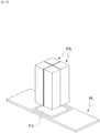
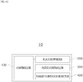
- a tissue diagnosis device for detecting a target substance from a tissue sample by using a patch which includes a mesh structural body forming micro-cavities and is configured to contain a substance in the micro-cavities
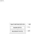
- the tissue diagnosis device including a plate supporter configured to support a plate on which a reaction region is placed and a sample is placed in the reaction region, a patch controller configured to support the patch which contains a labeling substance that specifically labels the target substance, and control a position of the patch relative to the reaction region so that the patch comes into contact with the reaction region and provides the labeling substance to the reaction region, and a target substance detector configured to detect the labeling substance and detect the target substance included in the tissue sample.
- the target substance detector may include an imaging module configured to acquire an image of the reaction region in which the tissue sample is placed.
- the target substance detector may include a measurement module configured to measure an amount of the target substance included in the tissue sample.
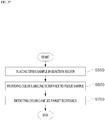
- a tissue diagnosis method for detecting a target substance from a tissue sample by using a patch which includes a mesh structural body forming micro-cavities and is configured to contain a substance in the micro-cavities, the tissue diagnosis method including placing the tissue sample in a reaction region, providing a fluorescence labeling substance for specifically labeling the target substance to the tissue sample by using a patch that contains the fluorescence labeling substance, and detecting the fluorescence-labeled target substance from the tissue sample.
- the fluorescence labeling substance may be a fluorescence labeling complex that includes a reaction derivative that reacts specifically with the target substance and a fluorescence marker for detecting the target substance.
- the detecting of the fluorescence-labeled target substance may be performed by obtaining a fluorescence image of the tissue sample.
- the detecting of the fluorescence-labeled target substance may be performed by measuring an amount of fluorescence emitted from the target substance included in the tissue sample.
- the detecting of the fluorescence-labeled target substance may include obtaining information on distribution of the target substance in the tissue sample.
- the target substance may be a target base sequence included in the tissue sample, the fluorescence labeling substance may include a fluorescence-labeled nucleic acid probe, and the nucleic acid probe may bind complementarily to the target base sequence.
- the target substance may be a target protein included in the tissue sample, the fluorescence labeling substance may include a fluorescence-labeled antibody, and the antibody may bind specifically to the target protein.
- the providing of the fluorescence labeling substance to the tissue sample may include contacting the patch containing the fluorescence labeling substance with the tissue sample, and when the patch is in contact with the tissue sample, the fluorescence labeling substance may be allowed to move to the reaction region.
- the providing of the fluorescence labeling substance to the tissue sample may include separating the patch containing the fluorescence labeling substance from the tissue sample, and when the patch is separated from the tissue sample, a residual fluorescence labeling substance that has not bound to the target substance of the fluorescence labeling substance may be removed from the reaction region.
- a tissue diagnosis method for detecting a target substance from a tissue sample by using a patch which includes a mesh structural body forming micro-cavities and is configured to contain a substance in the micro-cavities, the tissue diagnosis method including placing the tissue sample in a reaction region, providing staining substance to the tissue sample by using a patch that contains color labeling substance for assigning color to the target substance, and detecting the color-assigned target substance.
- the color labeling substance may be a color labeling complex that includes a reaction derivative that reacts specifically with the target substance and a color marker for detecting the target substance.
- the detecting of the color-assigned target substance may be performed by acquiring an image of the tissue sample.
- the detecting of the color-labeled target substance may include obtaining an amount of the color-labeled target substance in the tissue sample.
- the detecting of the color-labeled target substance may include obtaining a distribution of color-labeled regions in the tissue sample.
- the target substance may be a target base sequence included in the tissue sample, the color labeling substance may include a nucleic acid probe that binds complementarily to the target base sequence.
- the target substance may be a target protein included in the tissue sample, the color labeling substance may include an antibody to which a marker for inducing color labeling is attached, and the antibody may bind specifically to the target protein.
- the providing of the color labeling substance to the tissue sample may include contacting the patch containing the color labeling substance with the tissue sample, and when the patch is in contact with the tissue sample, the color labeling substance may be allowed to move to the reaction region.
- the providing of the color labeling substance to the tissue sample may include separating the patch containing the color labeling substance from the tissue sample, and when the patch is separated from the tissue sample, a residual color labeling substance that has not bound to the target substance of the color labeling substance may be removed from the reaction region.
- a tissue diagnosis method for detecting a target substance from a tissue sample by using a patch which includes a mesh structural body forming micro-cavities and is configured to contain a substance in the micro-cavities, the tissue diagnosis method including placing the tissue sample in a reaction region, providing a first fluorescence labeling substance for specifically labeling a first target substance to the tissue sample by using a patch that contains the first fluorescence labeling substance, and providing a second fluorescence labeling substance for specifically labeling a second target substance to the tissue sample by using a patch that contains the second fluorescence labeling substance.
- a wavelength band from which fluorescence emitted from the first fluorescence labeling substance is detected and a wavelength band from which fluorescence emitted from the second fluorescence labeling substance is detected may be different from each other, and the tissue diagnosis method may further include, after the providing of the second florescence labeling substance to the tissue sample, detecting the first target substance and the second target substance included in the tissue sample.
- the tissue diagnosis method may further include, after the providing of the first fluorescence labeling substance to the tissue sample, detecting the first target substance included in the tissue sample by detecting fluorescence emitted from the first fluorescence labeling substance, and may further include, after the providing of the second fluorescence labeling substance to the tissue sample, detecting the second target substance included in the tissue sample by detecting fluorescence emitted from the second fluorescence labeling substance.
- the wavelength band from which the fluorescence emitted from the first fluorescence labeling substance is detected and the wavelength band from which the fluorescence is emitted from the second fluorescence labeling substance is detected may at least partially overlap each other, and the detecting of the fluorescence emitted from the second fluorescence labeling substance may be performed by comparing fluorescence detected from the tissue sample after the second fluorescence labeling substance is provided to the tissue sample and fluorescence detected from the tissue sample before the second fluorescence labeling substance is provided to the tissue sample.
- a substance labeling patch including a labeling substance that binds to a target substance included in a tissue sample to label the target substance, and a mesh structural body having a mesh structure forming micro-cavities in which the labeling substance is contained that is configured to come into contact with the tissue sample and provide the labeling substance to a reaction region in which the target substance is placed.
- the target substance may be DNA included in the tissue sample.
- the labeling substance may be a fluorescence labeling substance.
- the fluorescence labeling substance may include a fluorescence-labeled antibody, and the target substance may be a target protein included in the tissue sample.
- the fluorescence labeling substance may include a fluorescence-labeled nucleic acid probe, and the target substance may be a target base substance included in the tissue sample.
- the labeling substance may be a color labeling substance.
- the color labeling substance may include an enzyme-attached antibody, and the target substance may be a target protein included in the sample.
- the color labeling substance may include hematoxylin, and the target substance may be a nucleus included in the sample.
- containing, providing, and absorption of a substance can be easily performed.
- a reaction region for a substance can be provided or a predetermined environment can be provided to a target region.
- diagnosis performed with a tissue as a sample can be more conveniently performed, and a diagnosis result can be promptly obtained.
- providing and absorption of a substance can be properly adjusted using a path, and an amount of a solution consumed for diagnosis can be significantly reduced.
- tissue diagnosis can be performed by simultaneously detecting a plurality of targets.
- a patch for managing a liquid substance is disclosed.
- the liquid substance may mean a substance which is in a liquid state and can flow.
- the liquid substance may be a substance formed of a single component having fluidity.
- the liquid substance may be a mixture that includes a substance formed of a plurality of components.
- the liquid substance when the liquid substance is a substance formed of a single component, the liquid substance may be a substance formed of a single chemical element or a compound including a plurality of chemical elements.
- the liquid substance is a mixture
- a portion of the substance formed of a plurality of components may serve as a solvent, and the other portion may serve as a solute. That is, the mixture may be a solution.
- a plurality of components constituting the mixture which forms the substance may be uniformly distributed.
- the mixture including the substance formed of a plurality of components may be a uniformly mixed mixture.
- the substance formed of a plurality of components may include a solvent and a substance that is not dissolved in the solvent and is uniformly distributed.
- a portion of the substance formed of a plurality of components may be non-uniformly distributed.
- the non-uniformly distributed substance may include non-uniformly distributed particle components in the solvent.
- the non-uniformly distributed particle components may be in a solid phase.
- a substance that may be managed using the patch may be in a state of 1) a liquid formed of a single component, 2) a solution, or 3) a colloid, or according to circumstances, may be in a state in which 4) solid particles are non-uniformly distributed within another liquid substance.
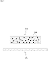
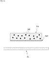
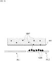
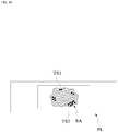
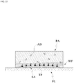
- FIGS. 1 and 2 are views illustrating an example of a patch according to the present application.
- the patch according to the present application will be described below with reference to FIGS. 1 and 2 .
- a patch PA may include a mesh structural body NS and a liquid substance.
- a base substance BS and an additive substance AS may be taken into consideration separately.
- the patch PA may be in a gel state(gel type).
- the patch PA may be implemented as a gel-type structural body in which colloidal molecules are bound and mesh tissues are formed.
- the patch PA according to the present application is a structure for managing a liquid substance SB, and may include a three-dimensional mesh(net-like) structural body NS.
- the mesh structural body NS may be a continuously distributed solid structure.
- the mesh structural body NS may have a mesh structure in which a plurality of micro-threads are intertwined.
- the mesh structural body NS is not limited to the mesh form in which the plurality of micro-threads are intertwined, and may also be implemented in the form of an arbitrary three-dimensional matrix that is formed by connection of a plurality of micro-structures.
- the mesh structural body NS may be a frame structural body that includes a plurality of micro-cavities. In other words, the mesh structural body NS may form a plurality of micro-cavities MC.
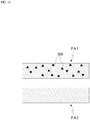
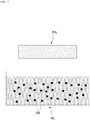
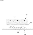
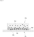
- FIG. 2 illustrates a structure of a patch according to an embodiment of the present application.
- the mesh structural body of the patch PA may have a sponge structure SS.
- the mesh structural body of the sponge structure SS may include a plurality of micro-holes MH.
- micro-holes MH and the micro-cavities MC may be used interchangeably, and unless particularly mentioned otherwise, the term micro-cavities MC is defined as encompassing the concept of the micro-holes MH.
- the mesh structural body NS may have a regular or irregular pattern. Furthermore, the mesh structural body NS may include both a region having a regular pattern and a region having an irregular pattern.
- a density of the mesh structural body NS may have a value within a predetermined range.
- the predetermined range may be set within a limit in which the form of the liquid substance SB captured in the patch PA is maintained in a form that corresponds to the patch PA.
- the density may be defined as a degree to which the mesh structural body NS is dense or a mass ratio, a volume ratio, or the like that the mesh structural body NS occupies in the patch.
- the patch according to the present application may manage the liquid substance SB by having a three-dimensional mesh structure.
- the patch PA according to the present application may include the liquid substance SB, and the fluidity of the liquid substance SB included in the patch PA may be limited by the form of the mesh structural body NS of the patch PA.
- the liquid substance SB may freely flow within the mesh structural body NS.
- the liquid substance SB is placed in the plurality of micro-cavities formed by the mesh structural body NS.
- An exchange of liquid substance SB may occur between neighboring micro-cavities.
- the liquid substance SB may be present in a state in which the liquid substance SB permeating into a frame structural body that forms the mesh tissues.
- nano-sized pores into which the liquid substances SB may permeate may be formed in the frame structural body.
- whether to the liquid substance SB is filled in the frame structural body of the mesh structure may be determined depending on a molecular weight or a particle size of the liquid substance SB to be captured in the patch PA.
- a substance having a relatively large molecular weight may be captured in the micro-cavities, and a substance having a relatively small molecular weight may be captured by the frame structural body and filled in the micro-cavities and/or the frame structural body of the mesh structural body NS.
- the term "capture” may be defined as a state in which the liquid substance SB is placed in the plurality of micro-cavities and/or nano-sized holes formed by the mesh structural body NS.
- the state in which the liquid substance SB is captured in the patch PA is defined as including a state in which the liquid substance SB may flow between the micro-cavities and/or the nano-sized holes.
- the base substance BS and the additive substance AS may be taken into consideration separately as the liquid substance SB.
- the base substance BS may be a liquid substance SB having fluidity.
- the additive substance AS may be a substance that is mixed with the base substance BS and has fluidity.
- the base substance BS may be a solvent.
- the additive substance AS may be a solute that is dissolved in the solvent or may be particles that are not melted in the solvent.
- the base substance BS may be a substance capable of flowing inside a matrix formed by the mesh structural body NS.
- the base substance BS may be uniformly distributed in the mesh structural body NS or may be distributed only in a partial region of the mesh structural body NS.
- the base substance BS may be a liquid having a single component.
- the additive substance AS may be a substance that is mixed with the base substance BS or dissolved in the base substance BS.
- the additive substance AS may serve as a solute while the base substance BS is a solvent.
- the additive substance AS may be uniformly distributed in the base substance BS.
- the additive substance AS may be fine particles that are not dissolved in the base substance BS.
- the additive substance AS may include colloidal molecules and fine particles such as microorganisms.
- the additive substance AS may include particles larger than the micro-cavities formed by the mesh structural body NS.
- the size of the micro-cavities is smaller than the size of the particles included in the additive substance AS, fluidity of the additive substance AS may be limited.
- the additive substance AS may include a component that is selectively included in the patch PA.
- the additive substance AS does not necessarily refer to a substance that is lower in quantity or inferior in function in comparison to the above-described base substance BS.
- characteristics of the liquid substance SB captured in the patch PA may be presumed as characteristics of the patch PA. That is, the characteristics of the patch PA may depend on characteristics of a substance captured in the patch PA.
- the patch PA may include the mesh structural body NS.
- the patch PA may manage the liquid substance SB through the mesh structural body NS.
- the patch PA may allow the liquid substance SB captured in the patch PA to maintain at least some of its unique characteristics.
- diffusion of a substance may occur in a region of the patch PA in which the liquid substance SB is distributed, and a force such as surface tension may come into action.
- the patch PA may provide a liquid environment in which diffusion of a target substance is caused due to thermal motion of a substance or a difference in density or concentration thereof.
- diffusion refers to a phenomenon in which particles that constitute a substance are spread from a side at which concentration is high to a side at which a concentration is low due to a difference in concentration.
- Such a diffusion phenomenon may be basically understood as a phenomenon that occurs due to motion of molecules (translational motion in a gas or liquid, vibrational motion in a solid, and the like).
- diffusion in addition to referring to the phenomenon in which particles are spread from a side at which a concentration is high toward a side at which a concentration is low due to a difference in concentration or density, “diffusion” also refers to a phenomenon in which particles move due to irregular motion of molecules that occurs even when a concentration is uniform.
- the expression “irregular motion” may also have the same meaning as “diffusion” unless particularly mentioned otherwise.
- the diffused substance may be a solute that is dissolved in the liquid substance SB, and the diffused substance may be provided in a solid, liquid, or gas state.
- a non-uniformly-distributed substance in the liquid substance SB captured by the patch PA may be diffused in a space provided by the patch PA.
- the additive substance AS may be diffused in a space defined by the patch PA.
- the non-uniformly-distributed substance or the additive substance AS in the liquid substance SB managed by the patch PA may be diffused within the micro-cavities provided by the mesh structural body NS of the patch PA.
- a region in which the non-uniformly-distributed substance or the additive substance AS may be diffused may be changed by the patch PA being connected or coming into contact with another substance.
- the substance or the additive substance AS may continuously move due to irregular motion of molecules inside the patch PA and/or within the external region connected to the patch PA.
- the patch PA may be implemented to exhibit a hydrophilic or hydrophobic property.
- the mesh structural body NS of the patch PA may have a hydrophilic or hydrophobic property.
- the mesh structural body NS may be able to manage the liquid substance SB more effectively.
- the base substance BS may be a polar hydrophilic substance or a nonpolar hydrophobic substance.
- the additive substance AS may exhibit a hydrophilic or hydrophobic property.
- the properties of the liquid substance SB may be related to the base substance BS and/or the additive substance AS.
- the liquid substance SB may be hydrophilic
- the liquid substance SB may be hydrophobic
- the liquid substance SB may be hydrophilic or hydrophobic.
- the patch PA may be solely used, a plurality of patches PA may be used, or the patch PA may be used with another medium to induce a desired reaction.
- functional aspects of the patch PA will be described.
- the patch PA is assumed as being a gel type that may include a hydrophilic solution.
- the mesh structural body NS of the patch PA is assumed to have a hydrophilic property.
- the scope of the present application should not be interpreted as being limited to the gel-type patch PA having a hydrophilic property.
- a gel-type patch PA that includes a solution exhibiting a hydrophobic property
- a gel-type patch PA from which a solvent is removed and even a sol-type patch PA may belong to the scope of the present application.
- the patch according to the present application may have some useful functions. In other words, by capturing the liquid substance SB, the patch may become involved in behavior of the liquid substance SB.
- a reservoir function in which a state of the substance is defined in a predetermined region formed by the patch PA and a channeling function in which a state of the substance is defined in a region including an external region of the patch PA will be separately described.
- the patch PA according to the present application may capture the liquid substance SB.
- the patch PA may perform a function as a reservoir.
- the patch PA may capture the liquid substance SB in the plurality of micro-cavities formed in the mesh structural body NS using the mesh structural body NS.
- the liquid substance SB may occupy at least a portion of the fine micro-cavities formed by the three-dimensional mesh structural body NS of the patch PA or be penetrated in the nano-sized pores formed in the mesh structural body NS.
- the liquid substance SB placed in the patch PA does not lose properties of a liquid even when the liquid substance SB is distributed in the plurality of micro-cavities. That is, the liquid substance SB has fluidity even in the patch PA, and diffusion of a substance may occur in the liquid substance SB distributed in the patch PA, and an appropriate solute may be dissolved in the substance.
- the patch PA may capture a target substance due to the above-described characteristics.
- the patch PA may have resistance to a change in an external environment within a predetermined range. In this way, the patch PA may maintain a state in which the substance is captured therein.
- the liquid substance SB which is a target to be captured, may occupy the three-dimensional mesh structural body NS.
- the patch PA containing the liquid substance is defined to encompass a case in which the liquid substance is contained in a space formed by the mesh structure and/or a case in which the liquid substance is contained in the frame structural body constituting the mesh structural body NS.
- the patch PA may contain the liquid substance SB.
- the patch PA may contain the liquid substance SB, due to an attractive force that acts between the mesh structural body NS of the patch PA and the liquid substance SB.
- the liquid substance SB may be bound to the mesh structural body NS with an attractive force of a predetermined strength or higher and contained in the patch PA.
- Properties of the liquid substance SB contained in the patch PA may be classified in accordance with properties of the patch PA. More specifically, when the patch PA exhibits a hydrophilic property, the patch PA may be bound to a hydrophilic liquid substance SB which is polar in general and contain the hydrophilic liquid substance SB in the three-dimensional micro-cavities. Alternatively, when the patch PA exhibits a hydrophobic property, the hydrophobic liquid substance SB may be contained in the micro-cavities of the three-dimensional mesh structural body NS.
- the amount of substance that may be contained in the patch PA may be proportional to a volume of the patch PA.
- the amount of substance contained in the patch PA may be proportional to an amount of three-dimensional mesh structural body NS that serves as a support body that contributes to the form of the patch PA.
- the amount of substance contained in the patch PA may be reduced due to evaporation, loss, etc. with time.
- the substance may be additionally injected into the patch PA to increase or maintain the content of the substance contained in the patch PA.
- a moisture keeping agent for suppressing evaporation of moisture may be added to the patch PA.
- the patch PA may be implemented in a form in which it is easy to store the liquid substance SB. This signifies that, when the substance is affected by environmental factors such as humidity level, amount of light, and temperature, the patch PA may be implemented to minimize denaturalization of the substance. For example, to prevent the patch PA from being denaturalized due to external factors such as bacteria, the patch PA may be treated with a bacteria inhibitor.
- a liquid substance SB having a plurality of components may be contained in the patch PA.
- the substance formed of a plurality of components may be placed together in the patch PA before a reference time point, or a primarily-injected substance may be first contained in the patch PA and then a secondary substance may be contained in the patch PA after a predetermined amount of time.
- a liquid substance SB formed of two components may be contained in the patch PA upon manufacturing the patch PA, only one component may be contained in the patch PA upon manufacturing the patch PA and the other component may be contained therein later, or the two components may be sequentially contained in the patch PA after the patch PA is manufactured.
- the substance contained in the patch may exhibit fluidity, and the substance may move irregularly or be diffused due to molecular motion in the patch PA.
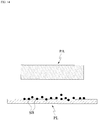
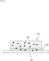
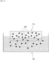
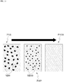
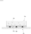
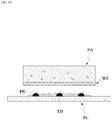
- FIGS. 3 and 4 are views illustrating providing a reaction space as an example of a function of the patch according to the present application.
- the patch PA may perform a function of providing a space.
- the patch PA may provide a space in which the liquid substance SB may move through a space formed by the mesh structural body NS and/or a space constituting the mesh structural body NS.
- the patch PA may provide a space for activity other than diffusion of particles and/or irregular motion of particles (hereinafter referred to as activity other than diffusion).
- the activity other than diffusion may refer to a chemical reaction, but is not limited thereto, and may also refer to a physical state change. More specifically, the activity other than diffusion may include a chemical reaction in which a chemical composition of the substance changes after the activity, a specific binding reaction between components included in the substance, homogenization of solutes or particles included in the substance and non-uniformly distributed therein, condensation of some components included in the substance, or a biological activity of a portion of the substance.
- the plurality of substances When a plurality of substances become involved in the activity, the plurality of substances may be placed together in the patch PA before a reference time point. The plurality of substances may be sequentially inserted into the patch PA.
- the activity may be promoted or a start of the activity may be induced by changing a temperature condition of the patch PA or adding an electrical condition thereto.
- a first substance SB1 and a second substance SB2 placed in the patch PA may react inside the patch PA and be deformed into a third substance SB3 or generate the third substance SB3.
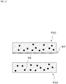
- Movement of a substance may occur between the patch PA and an external region.
- the substance may be moved from the patch PA to the external region of the patch PA or may be moved from the external region to the patch PA.
- the patch PA may form a substance movement path or get involved in movement of the substance. More specifically, the patch PA may become involved in movement of the liquid substance SB captured in the patch PA or become involved in movement of an external substance through the liquid substance SB captured in the patch PA.
- the base substance BS or the additive substance AS may move out from the patch PA, or an external substance may be introduced from an external region to the patch PA.
- the patch PA may provide a substance movement path. That is, the patch PA may become involved in movement of the substance and provide a substance movement channel.
- the patch PA may provide a substance movement channel based on unique properties of the liquid substance SB.
- the patch PA may be in a state in which the liquid substance SB is movable between the patch PA and the external region or a state in which the liquid substance SB is immovable between the patch PA and the external region.
- the patch PA may have unique functions.
- irregular motion and/or diffusion of the substance are fundamental causes of movement of the liquid substance SB between the patch PA and the external region.
- controlling an external environmental factor e.g., controlling a temperature condition, controlling an electrical condition, or the like
- controlling a temperature condition, controlling an electrical condition, or the like in order to control movement of a substance between the patch PA and the external region has already been described.
- a flow may occur between the liquid substance SB captured in the patch PA and/or the substance placed in the external region.
- substance movement may occur between the liquid substance SB captured in the patch PA and the external region.
- the liquid substance SB or some components of the liquid substance SB may be diffused to the external region or moved due to irregular motion.
- an external substance placed in the external region or some components of the external substance may be diffused to the liquid substance SB in the patch PA or moved due to irregular motion.
- the state in which the substance is movable may be caused by contact.
- the contact may refer to connection between the liquid substance SB captured in the patch PA and the external region.
- Contact may refer to at least a partial overlap between a flow region of the liquid substance SB and the external region.
- the contact may refer to the external substance being connected to at least a portion of the patch PA. It may be understood that the range in which the captured liquid substance SB may flow is expanded in the state in which the substance is movable. In other words, in the state in which the substance is movable, the range in which the liquid substance SB may flow may be expanded to include at least a portion of the external region of the captured liquid substance SB.
- the range in which the captured liquid substance SB may flow may be expanded to include at least a portion of the external region in contact. More specifically, when the external region is an external plate, the region in which the liquid substance SB may flow may be expanded to include a region of the external plate in contact with the liquid substance SB.
- substance movement may not occur between the liquid substance SB captured in the patch PA and the external region.
- substance movement may respectively occur in the liquid substance SB captured in the patch PA and in external substance placed in the external region.
- the state in which the substance is immovable may be a state in which the contact is released. In other words, in the state in which contact between the patch PA and the external region is released, substance movement is not possible between the liquid substance SB remaining in the patch PA and the external region or the external substance.
- the state in which the contact is released may refer to a state in which the liquid substance SB captured in the patch PA is not connected to the external region.
- the state in which the contact is released may refer to a state in which the liquid substance SB is not connected to an external substance placed in the external region.
- the state in which movement of the substance is impossible may be caused by separation between the patch PA and the external region.
- movable state has a meaning differentiated from that of "immovable state”
- a transition may occur between the states due to an elapse of time, an environmental change, and the like.
- the patch PA may be in the immovable state after being in the movable state , in the movable state after being in the immovable state, or may be in the movable state again, after being in the immovable state after being in the movable state.
- the patch PA may deliver at least a portion of the liquid substance SB captured in the patch PA to a desired external region.
- the delivery of the substance may refer to separation of a portion of the liquid substance SB captured in the patch PA from the patch PA due to a predetermined condition being satisfied.
- the separation of the portion of the liquid substance SB may refer to the portion of the substance being extracted, emitted, or released from a region that is affected by the patch PA. This is a concept subordinate to the above-described channeling function of the patch PA, and may be understood as defining transfer(delivery) of the substance placed in the patch PA to the outside of the patch PA.
- the desired external region may be another patch PA, a dried region, or a liquid region.
- the predetermined condition for the delivery to occur may be set as an environmental condition such as a temperature change, a pressure change, a change in an electrical characteristic, and a change in a physical state.
- an environmental condition such as a temperature change, a pressure change, a change in an electrical characteristic, and a change in a physical state.
- delivery the above-described function of the patch PA will be referred to as "delivery.”
- the delivery may occur between the patch PA and the external region, via the state in which the liquid substance SB is movable and the state in which the liquid substance SB is immovable between the patch PA and the external region.
- the liquid substance SB when the liquid substance SB is in the movable state, the liquid substance SB may be diffused between the patch PA and the external region or may be moved to the external region due to irregular motion.
- the base solution and/or the additive substance AS included in the liquid substance SB may be moved from the patch PA to the external region.
- the liquid substance SB In the state in which the liquid substance SB is immovable, the liquid substance SB is unable to move between the patch PA and the external region.
- a portion of the substance that has moved from the patch PA to the external region due to diffusion and/or irregular motion of the liquid substance SB become unable to move back to the patch PA.
- a portion of the liquid substance SB may be provided to the external region.
- the delivery may be performed due to a difference between an attractive force between the liquid substance SB and the mesh structural body NS and an attractive force between the liquid substance SB and the external region or the external substance.
- the attractive force may be caused by similarity between polarities or a specific binding relationship.
- liquid substance SB is hydrophilic and the external region or the external substance is more hydrophilic than the mesh structural body NS
- at least a portion of the liquid substance SB captured in the patch PA may be provided to the external region via the movable state and the immovable state.
- the delivery of the liquid substance SB may also be performed selectively. For example, when a specific binding relationship exists between some components included in the liquid substance SB and the external substance, some of the ingredients may be selectively delivered via the state in which the substance is movable and the state in which the substance is immovable.
- the patch PA provides a substance to an external plate PL, which is in a form of a flat plate
- a substance that binds specifically to a portion of the liquid substance SB captured in the patch PA e.g., a portion of a solute
- the patch PA may selectively deliver a portion of the solute that binds specifically to the substance applied on the external plate PL from the patch PA to the plate PL via the movable state and the immovable state.
- liquid substance SB is provided from the patch PA to a separate external plate PL.
- a case in which the substance is moved from the patch PA to a plate PL, such as a slide glass, may be taken into consideration.
- the portion of the substance SB captured in the patch PA is diffused to the plate PL or moved due to irregular motion.
- the portion of the substance that has been moved from the patch PA to the plate PL that is, the portion of the liquid substance SB
- the portion of the substance may be provided from the patch PA to the plate PL.
- the portion of the substance being provided may be the additive substance AS.
- an attractive force and/or binding force that acts between the substance and the plate PL should be present, and the attractive force and/or the binding force should be larger than the attractive force acting between the substance and the patch PA. Therefore, if the above-described "delivery condition" is not satisfied, delivery of a substance may not occur between the patch PA and the plate PL.
- the delivery of a substance may be controlled by providing a temperature condition or an electrical condition to the patch PA.
- the movement of a substance from the patch PA to the plate PL may depend on an extent of a contact area between the patch PA and the plate PL.
- the substance movement efficiency between the patch PA and the plate PL may be increased or decreased in accordance with an extent of an area in which the patch PA and the plate PL come into contact.
- the patch PA When the patch PA includes a plurality of components, only some of the components may be selectively moved to the external plate PL. More specifically, a substance that binds specifically to some of the plurality of components may be fixed to the external plate PL. In this case, the substance fixed to the external plate PL may be in a liquid or solid state, or may be fixed to a different region. In this case, a portion of the substance of the plurality of components moves to the plate PL and binds specifically to the plate PL due to contact between the patch PA and the different region, and when the patch PA is separated from the plate PL, only some of the components may be selectively released to the plate PL.
- FIGS. 5 to 7 illustrate delivery of a substance from the patch PA to the external plate PL as an example of delivery of a substance from among the functions of the patch PA according to the present application.
- a portion of a substance contained in the patch PA may be provided to the plate PL.
- providing of the substance may become possible by the patch PA coming into contact with the plate so that the substance is movable.
- a water film WF may be formed in the vicinity of a contact surface at which the plate and the patch PA come into contact, and the substance may be movable through the formed water film WF.
- the substance having fluidity SL may be a liquid substance that is held in other containing space or that is flowing.
- the patch PA and the substance having fluidity come into contact (for example, the patch PA is put into a solution), at least a portion of the liquid substance SB captured in the patch PA may be diffused or moved due to irregular motion to the substance having fluidity SL.
- the patch PA and the substance having fluidity SL are separated, a portion of the liquid substance SB that has been moved from the patch PA to the substance having fluidity become unable to move back to the patch PA so that a portion of the substance in the patch PA may be provided to the substance having fluidity.
- the substance movement between the patch PA and the substance having fluidity SL may depend on an extent of a contact area between the patch PA and the substance having fluidity SL.
- the substance movement efficiency between the patch PA and the substance having fluidity SL may be increased or decreased in accordance with an extent of an area at which the patch PA and the substance having fluidity SL come into contact (for example, a depth at which the patch PA is immersed into a solution or the like).
- the substance movement between the patch PA and the substance having fluidity SL may be controlled through physical separation between the patch PA and the substance having fluidity.
- a partial concentration of the additive substance AS in the liquid substance SB and a partial concentration of the additive substance AS in the substance having fluidity may be different, and the additive substance AS may be provided from the patch PA to the substance having fluidity.
- the physical separation between the patch PA and the substance having fluidity SL is not essential. For example, when a force(driving force/ casual force) that causes a substance to move from the patch PA to a liquid having fluidity disappears or is decreased to a reference value or lower, the movement of the substance may be stopped.
- the above-described “delivery condition" between the patch PA and the substance having fluidity SL may not be required. It may be understood that substances that have already moved to the substance having fluidity SL are diffused and/or moved due to irregular motion in the substance having fluidity SL, and the substance has been provided to the substance having fluidity SL when a distance between the moved substance and the patch PA become larger a predetermined distance.
- FIGS. 8 to 10 illustrate delivery of a substance from the patch PA to the substance having fluidity as an example of delivery of a substance from among the functions of the patch PA according to the present application.
- the patch PA may deliver a portion of a substance contained in the patch PA to an external substance having fluidity.
- the delivery of the portion of the contained substance may be performed by the patch PA being inserted into or coming into contact with the substance having fluidity so that substance movement is possible between the liquid substance SB captured in the patch PA and the substance having fluidity.
- a substance is moved from the patch PA to another patch PA.
- at least a portion of the liquid substance B provided in the patch PA may be moved to the other patch PA.
- the liquid substance SB provided in each patch PA may be diffused and moved to the other patch PA. In this case, due to the movement of the substance, a concentration of the liquid substance SB provided in each patch PA may be changed. Also in the present embodiment, as described above, the patch PA and the other patch PA may be separated, and a portion of the liquid substance SB in the patch PA may be provided to the other patch PA.
- the substance movement between the patch PA and the other patch PA may be performed through a change in an environmental condition including a change in a physical state.
- the substance movement between the patch PA and another patch PA may depend on an extent of a contact area between the patch PA and the other patch PA.
- the substance movement efficiency between the patch PA and the other patch PA may be increased or decreased in accordance with an extent of an area where the patch PA comes into contact with the other patch PA.
- FIGS. 11 to 13 illustrate delivery of a substance from a patch PA1 to another patch PA2 as an example of delivery of a substance among the functions of the patch PA according to the present application.
- the patch PA1 may deliver a portion of a substance contained in the patch PA1 to the other patch PA2.
- the delivery of the portion of the substance may be performed by the patch PA1 coming into contact with the other patch PA2 and becoming a state in which a liquid substance SB captured in the patch PA1 and a substance captured in the other patch PA2 are exchangeable.
- “absorption” may be managed similarly as the above-described “delivery” in some embodiments.
- the "absorption” may be similar to the “delivery” in that a concentration of the liquid substance SB, particularly, a concentration of the additive substance AS, may be changed to control a direction in which the substance is moved.
- the “absorption” may also be similar to “delivery” in terms of controlling movement and selective absorption of a substance through a release of physical contact with the patch PA, and this may be clearly understood by those of ordinary skill in the art to which the present application pertains.
- the patch PA according to the present application may capture an external substance.
- the patch PA may pull in an external substance present outside a region defined by the patch PA toward a region affected by the patch PA.
- the pulled external substance may be captured along with the liquid substance SB of the patch PA.
- the pulling of the external substance may be caused by an attractive force between the external substance and the liquid substance SB already captured in the patch PA.
- the pulling of the external substance may be caused by an attractive force between the external substance and a region of the mesh structural body NS not occupied by the liquid substance SB.
- the pulling of the external substance may be caused by a force of surface tension.
- Absorption may be understood as a concept subordinate to the above-described channeling function of the patch PA, the concept defining movement of an external substance to the patch PA.
- the absorption may occur by the patch PA via a state in which the substance is movable and a state in which the substance is immovable.
- a substance that is absorbable by the patch PA may be in a liquid or solid state.
- absorption of the substance may be performed due to an attractive force between the solid state substance included in the external substance and the liquid substance SB placed in the patch PA.
- the absorption may be performed due to binding between the liquid external substance and the liquid substance SB placed in the patch PA.
- the external substance absorbed into the patch PA may be moved to the inside of the patch PA through the micro-cavities of the mesh structural body NS forming the patch PA or may be distributed on a surface of the patch PA. Positions at which the external substance is distributed may be set on the basis of a molecular weight or a particle size of the external substance.
- the form of the patch PA may be changed.
- the volume, color, and the like of the patch PA may be changed.
- the absorption into the patch PA may be activated or delayed by adding external conditions such as a temperature change and a physical state change to an absorption environment of the patch PA.
- the absorption will be described below as a function of the patch PA according to some examples of an external region that provides a substance to be absorbed into the patch PA when the absorption occurs.
- the patch PA absorbs an external substance from a external plate PL.
- An example of the external plate may include a plate PL in which the external substance may be placed while the external substance is not absorbed thereinto.
- a substance may be applied on the external plate PL.
- a substance may be applied in a form of powder on the plate PL.
- the substance applied on the plate PL may be a single component or a mixture of a plurality of components.
- the plate PL may have the shape of a flat plate.
- the shape of the plate PL may be deformed for improvement in ability to contain the substance or the like.
- a well may be formed to improve the ability to contain the substance
- a surface of the plate PL may be deformed by engraving or embossing, or a patterned plate PL may be used to improve contact with the patch PA.
- the absorption of a substance from the plate PL by the patch PA according to the present application may be performed through contact between the plate PL and the patch PA.
- a water film WF may be formed due to the liquid substance SB captured in the patch PA and/or the substance applied on the plate PL.
- the substance applied on the plate PL may be captured by the water film WF.
- the substance captured in the water film WF may freely flow within the patch PA.
- the water film WF may be moved along with the patch PA, and the substance applied on the plate PL may be absorbed into the patch PA.
- the substance applied on the plate PL may be absorbed into the patch PA as the patch PA is separated a predetermined distance or more apart from the plate PL.
- the liquid substance SB provided to the patch PA may not be moved to the plate PL, or only an insignificant amount thereof may be absorbed into the patch PA.
- a portion of or the entire substance applied on the plate PL may react specifically with a portion of or the entire substance captured in the patch PA.
- absorption of a substance from the plate PL by the patch PA may be selectively performed.
- the absorption may be performed selectively when the patch PA has a stronger attractive force than the plate PL with respect to a portion of the substance captured in the patch PA.
- a portion of the substance may be fixed to the plate PL.
- a portion of the substance may be fixed to the plate PL while another portion of the substance is applied to have fluidity or not be fixed.
- the substance excluding the portion of the substance fixed to the plate PL of the substance applied on the plate PL, may be selectively absorbed into the patch PA.
- the selective absorption may also occur due to polarities of a substance placed on the plate PL and a substance captured in the patch PA regardless of whether the substance is fixed.
- liquid substance SB captured in the patch PA is bound specifically to at least a portion of a substance applied on the plate PL
- only the portion of the substance applied on the plate PL bound specifically to the liquid substance SB may be absorbed into the patch PA when the patch PA is brought into contact with and then separated from the substance applied on the plate PL.
- a portion of the substance applied on the plate PL may react specifically with a substance fixed to the plate PL in advance.
- a remaining substance excluding the substance that reacts specifically with the substance fixed to the plate PL in advance of the substance being applied to the plate PL, may be absorbed into the patch PA.
- FIGS. 14 to 16 illustrate absorption of a substance from an external plate PL by the patch PA as an example of absorption of a substance from among the functions of the patch PA according to the present application.
- the patch PA may absorb a portion of a substance placed on the external plate PL from the external plate PL.
- the absorption of the substance may be performed by the patch PA coming into contact with the external plate PL, the water film WF being formed in the vicinity of a contact region between the external plate PL and the patch PA, and the substance being movable to the patch PA through the water film WF.
- the substance having fluidity SL may refer to a liquid external substance that is held in other containing space or that is flowing. More specifically, by having an environment in which the substance having fluidity SL and the liquid substance SB captured in the patch PA may flow to and from each other, a portion of or the entire substance having fluidity SL may be absorbed into the patch PA. In this case, the environment in which the substance having fluidity SL and the liquid substance SB may flow to and from each other may be formed by the patch PA coming into contact with at least a portion of the substance having fluidity SL.
- the patch PA When the patch PA comes into contact with the substance having fluidity SL, the patch PA may be in a state in which a substance is movable from the substance having fluidity SL. When the patch PA is separated from the substance having fluidity SL, at least a portion of the substance having fluidity SL may be absorbed into the patch PA.
- the absorption of a substance into the patch PA from the substance having fluidity SL may depend on a concentration difference between the substance captured in the patch PA and the substance having fluidity SL.
- concentration difference between the substance captured in the patch PA and the substance having fluidity SL.
- the absorption into the patch PA may also be controlled by adding an electrical factor or changing a physical condition. Further, without direct contact between the substance captured in the patch PA and a substance to be absorbed, the absorption of a substance may also be performed through indirect contact therebetween via a medium.
- FIGS. 17 to 19 illustrate absorption of a substance from the substance having fluidity SL by the patch PA as an example of absorption of a substance from among the functions of the patch PA according to the present application.
- the patch PA may absorb a portion of the substance having fluidity SL.
- the absorption of a substance may be performed by the patch PA being immersed into the substance having fluidity SL or coming into contact with the substance having fluidity SL so that the liquid substance SB captured in the patch PA and the substance having fluidity SL are movable to and from each other.
- the patch PA absorbs an external substance from another patch PA.
- the absorption of an external substance from another patch PA by the patch PA may be performed due to a difference in binding force between the absorbed external substance and the substance already captured in the patch PA and between the absorbed external substance and the external substance not absorbed into the patch PA.
- the absorbed substance exhibits hydrophilic property
- the patch PA exhibits hydrophilic property
- an attractive force between the absorbed substance and the patch PA is stronger than an attractive force between the other patch PA and the absorbed substance (that is, when the patch PA is more hydrophilic than the other patch PA)
- at least a portion of the external substance may be absorbed into the patch PA when the patch PA and the other patch PA are separated after being brought into contact.
- FIGS. 20 to 22 illustrate absorption of a substance from another patch PA4 by a patch PA3 as an example of absorption of a substance among the functions of the patch PA according to the present application.
- the patch PA3 may absorb a portion of a substance placed in the other patch PA4.
- the absorption of the substance may be performed by the patch PA3 coming into contact with the other patch PA4 so that a liquid substance SB captured in the patch PA3 and a liquid substance SB captured in the other patch PA4 are exchangeable.
- a binding force of the patch PA to the external substance absorbed thereinto may be changed in accordance with a proportion of a frame structural body of the three-dimensional mesh structural body NS constituting the patch PA with respect to the total volume of the patch PA. For example, as the proportion of a volume occupied by the frame structural body in the entire patch PA increases, the amount of substance captured in the structural body may be reduced. In this case, a binding force between the patch PA and a target substance may be reduced due to a reason such as reduction in a contact area between the target substance and the substance captured in the patch PA.
- ratios of materials that constitutes the mesh structural body NS may be adjusted during manufacturing process of the patch PA so that polarity of the patch PA is controlled.
- a concentration of the agarose may be controlled to adjust a degree of the absorption.
- the absorbed external substance may be separated from the other patch PA along with the patch PA.
- the patch PA according to the present application may perform a function of adjusting an environmental condition of a desired region.
- the patch PA may provide an environment due to the patch PA to the desired region.
- the environmental condition due to the patch PA may depend on the liquid substance SB captured in the patch PA.
- the patch PA may create a desired environment in a substance placed in an external region on the basis of characteristics of a substance accommodated in the patch PA or for a purpose of making the environment correspond to characteristics of the substance accommodated in the patch PA.
- the adjustment of the environment may be understood as changing an environmental condition of the desired region.
- the changing of the environmental condition of the desired region may be implemented in a form in which a region affected by the patch PA is expanded to include at least a portion of the desired region or a form in which an environment of the patch PA is shared with the desired region.
- the providing of an environment by the patch PA may be performed in a state in which a substance is movable between the patch PA and an external region subject to provide the environment.
- the providing of an environment by the patch PA may be performed through contact. For example, when the patch PA comes into contact with a desired region (for example, an external substance, a plate PL, or the like), a specific environment may be provided to the desired region by the patch PA.
- a desired region for example, an external substance, a plate PL, or the like
- the patch PA may adjust an environment of a target region TA by providing an environment with an appropriate pH, osmotic pressure, humidity level, concentration, temperature, and the like.
- the patch PA may provide fluidity (liquidity) to the target region TA or a target substance. Such providing of fluidity may occur due to movement of a portion of a substance captured in the patch PA.
- a moist environment may be provided to the target region TA through the liquid substance SB or the base substance BS captured in the patch PA.
- the environmental factors provided by the patch PA may be constantly maintained in accordance with a purpose.
- the patch PA may provide homeostasis to the desired region.
- the substance captured in the patch PA may be adapted to an environmental condition of the desired region
- the providing of an environment by the patch PA may result from diffusion of the liquid substance SB included in the patch PA. That is, when the patch PA and the desired region come into contact, a substance may be movable through a contact region that is formed due to contact between the patch PA and the desired region.
- an environmental change due to an osmotic pressure, an environmental change due to a change in ionic concentration, providing of a moist environment, and a change in a pH level may be implemented in accordance with a direction in which the substance is diffused.
- FIGS. 23 to 25 illustrate providing of a predetermined environment to an external plate PL by the patch PA as an example of providing of an environment among the functions of the patch PA according to the present application.
- the patch PA may provide a predetermined environment to an external plate PL on which a fourth substance SB4 and a fifth substance SB5 are placed.
- the patch PA may provide a predetermined environment to the plate PL for the fourth substance SB4 and the fifth substance SB5 to react and form a sixth substance SB6.
- the providing of the environment may be performed by the patch PA coming into contact with the plate PL so that a water film WF is formed in the vicinity of a contact region and the fourth substance SB4 and the fifth substance SB5 are captured in the water film WF.
- the patch PA according to the present application may be implemented to perform various functions by suitably applying the above-described functions of the patch PA.
- the patch PA may provide a reaction region for a substance.
- a reaction of a substance may occur in at least a portion of a spatial region affected by the patch PA.
- the reaction of a substance may be a reaction between liquid substances SB captured in the patch PA and/or a reaction between the captured liquid substance SB and a substance provided from the outside of the patch PA.
- the providing of a reaction region for a substance may activate or promote a reaction of a substance.
- the liquid substance SB captured in the patch PA may include at least one of a substance added upon manufacturing the patch PA, a substance additive into the patch PA after the manufacturing of the patch PA and contained in the patch PA, and a substance temporarily captured in the patch PA.
- a substance injected after the manufacturing of the patch PA may also act as a reaction initiator.
- the providing of a reaction region for a reaction related to the liquid substance SB captured in the patch PA may be a concept subordinate, in terms of embodiment, to the above-described Section 2.1.3 (that is, providing of reaction space).
- the providing of a reaction region for a reaction related to the liquid substance SB captured in the patch PA may consist of multiple concepts that perform combined functions of the above-described Section 2.1.3 and Section 2.2.4.2 (that is, absorption).
- the providing of a reaction region for a reaction related to the liquid substance SB captured in the patch PA is not limited thereto and may be implemented in the form in which two or more functions are combined.
- the function of absorption into the patch PA and the function of providing of a reaction space (hereinafter referred to as "providing function") are performed by a single patch PA.
- the absorption function and the providing function may be simultaneously-performed functions, functions performed at different time points, or functions sequentially performed to perform another function.
- the patch PA further including other functions in addition to the absorption and providing functions may also be considered as belonging to the present embodiment.
- the patch PA may perform a function of capturing a substance, and the substance may have fluidity even when the substance is captured.
- the non-uniform components may be diffused.
- the liquid substance SB may have a predetermined level of mobility due to irregular motion of particles. In this case, a reaction between substances, for example, specific binding between substances, may occur inside the patch PA.
- a reaction in a form in which a substance having fluidity that is newly captured in the patch PA and the substance that has been captured in the patch PA bind specifically to each other may also be possible.
- the reaction between the substance having fluidity and the substance that has been captured in the patch PA may also occur after the substance patch being separated from an space that has been provided.
- the patch PA absorbs the substance having fluidity from an arbitrary space
- the patch PA may be separated from the arbitrary space, and a reaction between the absorbed substance and the substance that has been captured in the patch PA may occur in the patch PA.
- the patch PA may allow a reaction of a substance captured therein to occur by performing the absorption function with respect to a substance having fluidity,.
- the absorption of the substance having fluidity by the patch PA may act as a trigger for a reaction between the absorbed substance and the substance that has been captured in the patch PA.
- the reaction may occur inside a space defined by the patch PA.
- a composition of the liquid substance SB captured in the patch PA may be changed due to the reaction occurring inside the patch PA.
- a substance captured inside the patch PA is a compound
- a chemical composition thereof may be changed before and after a reaction.
- a composition distribution of a substance may be changed in accordance with a position of the substance in the patch PA. For example, this may be due to diffusion or particles having an attractive force specific to another substance.
- a portion of the substance may be absorbed into the patch PA due to a concentration difference between the patch PA and a substance outside the patch PA (when a substance in contact with the patch PA is present, the corresponding substance), or the substance may be released from the patch PA to the substance outside the patch PA.
- the patch PA may perform a function of providing a space for at least a portion of the liquid substance SB contained in the patch PA to react.
- the patch PA may contain a substance and provide a reaction space for the contained substance.
- the reaction space provided by the patch PA may be the micro-cavities formed by the mesh structural body NS of the patch PA or a surface region of the patch PA.
- the reaction space may be the surface region of the patch PA.
- the reaction space provided by the patch PA may serve to provide a specific environmental condition. While a reaction occurs in the liquid substance SB placed in the patch PA, an environmental condition of the reaction may be adjusted by the patch PA.
- the patch PA may serve as a buffer solution.
- the patch PA does not require a container, separately.
- the reaction space of the patch PA is a surface of the patch PA, a reaction may be easily observed through the surface of the patch PA.
- the shape of the patch PA may be deformed into a shape that facilitates the observation.
- the liquid substance SB contained in the patch PA may be denaturalized or react with a different type of substance.
- the composition of the liquid substance SB contained in the patch PA may be changed with time.
- the reaction may refer to a chemical reaction in which a chemical formula is changed, a physical state change, or a biological reaction.
- the liquid substance SB contained in the patch PA may be a substance formed of a single component or a mixture including a plurality of components.
- the patch PA that performs a function of providing a substance movement path
- the patch PA may capture, absorb, release, and/or contain a substance having fluidity.
- Various embodiments of the patch PA that performs the function of providing a substance movement path may be implemented by each of the above-described functions of the patch PA or a combination thereof. However, a few embodiments will be disclosed for a better understanding.
- the patch PA may be implemented to perform functions described in Section 2.2.4.1 (that is, the section related to delivery) and Section 2.2.4.2 (that is, the section related to absorption) among the above-described functions of the patch PA.
- the absorption function and the delivery function may be provided together or sequentially provided.
- the patch PA may perform the absorption and delivery functions together to provide a substance movement path.
- the patch PA may absorb an external substance and provide the absorbed external substance to an external region, thereby providing a movement path to the external substance.
- the providing of the movement path of the external substance by the patch PA may be performed by absorbing the external substance and releasing the external substance. More specifically, the patch PA may come into contact with the external substance, absorb the external substance, come into contact with the external region, and deliver the external substance to the external region. In this case, the capturing of the external substance and the delivery of the captured external substance to the external region by the patch PA may be performed through a process similar to those of the above-described absorption and delivery.
- the external substance absorbed into the patch PA and provided may be in a liquid phase or a solid phase.
- the patch PA may allow a portion of the external substance to be provided to another external substance.
- the external substance and the other external substance may simultaneously come into contact with the patch PA.
- the external substance and the other external substance may come into contact with the patch PA at different time points.
- the external substance and the other external substance may come into contact with the patch PA at different time points.
- the external substances When the external substances come into contact with the patch PA at different time points, the external substance may come into contact with the patch PA first, and after the external substance and the patch PA are separated, the patch PA and the other external substance may come into contact.
- the patch PA may temporarily contain a substance captured from the external substance.
- the patch PA may simultaneously provide a substance movement path and additionally provide a time delay.
- the patch PA may perform a function of suitably adjusting an amount of substance provided to another external substance and a speed of such providing.
- Such a series of processes may be carried out in one direction with respect to the patch PA.
- absorption of a substance may be performed through a surface of the patch PA, an environment may be provided in an inner space of the patch PA, and the substance may be released through another surface facing the surface.
- the patch PA may perform the absorbing and releasing of a substance among the above-described functions of the patch PA and the providing of a reaction space for the substance simultaneously .
- the absorption and release of the substance and the providing of the reaction space may be performed simultaneously or sequentially.
- the patch PA in performing the processes of absorbing and releasing an external substance, may provide a reaction space to the absorbed external substance for at least a predetermined amount of time.
- the patch PA may provide a specific environment for at least some time to the liquid substance SB captured in the patch PA, including the absorbed external substance.
- the liquid substance SB that has been captured in the patch PA and the external substance captured in the patch PA may react inside the patch PA.
- the external substance absorbed into the patch PA may be affected by an environment provided by the patch PA.
- the substance released from the patch PA may include at least a portion of a substance generated through the reaction.
- the external substance may be released from the patch PA after the composition, characteristics, and the like of the external substance are changed.
- the absorbed substance may be released from the patch PA.
- the external substance being absorbed into the patch PA and being released from the patch PA may be understood as the external substance passing through the patch PA.
- the external substance that has passed through the patch PA may lose integrity due to a reaction inside the patch PA or an influence of an environment provided by the patch PA.
- the above-described processes of absorption of an external substance, reaction of a substance, and providing of the substance may be carried out in one direction.
- the absorption of a substance may be performed at one position of the patch PA
- the providing of an environment may be performed at another position of the patch PA
- the release of the substance may be performed at yet another position of the patch PA.
- FIGS. 26 to 28 illustrate providing of a substance movement path between two plates PL as an embodiment of the patch PA according to the present application.
- the patch PA may provide a substance movement path between a plate PL1 on which a seventh substance SB7 is applied and a plate PL2 on which an eighth substance SB8 is applied.
- the patch PA may come into contact with the plates PL1 and PL2 so that the seventh substance SB7 is moved through the patch PA and bound to the eighth substance SB8.
- the seventh substance SB7 and the eighth substance SB8 may be connected to the patch PA through a water film WF formed by the patch PA coming into contact with the plates PL1 and PL2.
- FIGS. 29 and 30 illustrate providing of a substance movement path between two patches as an embodiment of the patch PA according to the present application.
- a patch PA6 configured to provide the movement path may be in contact with a patch PA5 configured to contain a substance to be moved, and a patch PA7 configured to receive the substance to be moved.
- the patch PA6 configured to provide the movement path may come into contact with the patch PA5 configured to contain the substance to be moved and the patch PA7 configured to receive the substance to be moved, and the substance to be moved may be moved to the patch PA7 configured to receive the substance to be moved.
- the movement of the substance between the patches may be performed by a water film WF formed in the vicinity of a contact region between the patches.
- FIGS. 31 and 32 illustrate providing of a substance movement path between two patches as an embodiment of the patch according to the present application.
- a patch PA9 configured to provide the movement path may be in contact with a patch PA8 configured to contain a ninth substance SB9 and a patch PA10 configured to receive a substance.
- the patch PA9 providing the movement path may come into contact with the patch PA8 configured to contain the ninth substance SB9 to absorb the ninth substance SB9.
- the absorbed ninth substance SB9 may react with a tenth substance SB10 contained in the patch PA9, which is configured to provide the movement path, and generate an eleventh substance.
- An eleventh substance SB11 may be provided from the patch PA9 configured to provide the movement path to the patch PA 10 configured to receive the substance.
- the movement of a substance between the patches PA may be performed through a water film WF formed in the vicinity of a contact region between the patches PA.
- a patch PA may be solely used, or a plurality of patches PA may be used together.
- the plurality of patches PA being able to be used together includes a case in which the plurality of patches PA are sequentially used as well as a case in which the plurality of patches PA are used simultaneously.
- the patches PA may perform different functions.
- each patch PA of the plurality of patches PA may contain the same substance, the plurality of patches PA may also contain different substances.
- the patches PA may not come into contact with each other such that substance movement does not occur between the patches PA, or a desired function may be performed in a state in which substances contained in the patches PA are exchangeable.
- the plurality of patches PA used together may be manufactured in shapes similar to each other or in the same size, the plurality of patches PA may be used together even when the plurality of patches PA have different shapes.
- Each patch PA constituting the plurality of patches PA may be manufactured such that densities of the mesh structural bodies NS are different or components constituting the mesh structural bodies NS are different.
- the plurality of patches PA may come into contact with a single target region TA.
- the plurality of patches PA may come into contact with the single target region TA and perform a desired function.
- the plurality of patches PA may come into contact with different target regions TA.
- the plurality of patches PA may respectively come into contact with corresponding target regions TA and perform a desired function.
- the plurality of patches PA may come into contact with a substance applied on the target region TA.
- the substance applied on the target region TA may be fixed or have fluidity.
- the desired function may be a function of providing or absorbing the substance.
- each patch PA does not necessarily provide the same substance or absorb the same substance, and the patches PA may provide different substances to the target region TA or absorb different components from a substance placed in the target region TA.
- the desired function may be different for each patch PA constituting the plurality of patches PA.
- one patch PA may perform the function of providing a substance to the target region TA
- another patch PA may perform the function of absorbing the substance from the target region TA.
- the plurality of patches PA may include different substances, and the different substances may be provided to a single target region TA and used to induce a desired reaction.
- the plurality of components may be contained in a plurality of patches PA respectively and provided to the target region TA.
- Such use of the plurality of patches PA may be particularly useful when properties of substances required for a desired reaction are lost or altered when the substances required for the reaction being mixed for reasons such as being contained in a single patch PA.
- the substances formed of different components may be provided to the target region TA.
- the plurality of patches PA may be used to detect a plurality of specific bindings from the substances applied on the target region TA, by providing the substances including different components.
- the plurality of patches PA may include substances formed of the same component, but each patch PA may have a different concentration with respect to the substance formed of the same component.
- the plurality of patches PA including the substances formed of the same component may come into contact with the target region TA and be used to determine an influence in accordance with a concentration of the substance included in the plurality of patches PA.
- the patches PA may be grouped into more efficient forms and used.
- the configuration of the plurality of patches PA being used may be changed every time the plurality of patches PA are used.
- the plurality of patches PA may be manufactured in the form of a cartridge and used. In this case, the form of each patch PA being used may be suitably standardized and manufactured.
- the plurality of patches PA in the form of a cartridge may be suitable when patches PA configured to contain a plurality of types of substances are manufactured to be used by being chosen as necessary.
- a combination of specific reactions to be detected may be changed every time the detection is performed.
- FIG. 33 illustrates a case in which the plurality of patches PA are used together as an embodiment of the patch PA according to the present application.
- the plurality of patches PA according to an embodiment of the present application may simultaneously come into contact with a target region TA placed on a plate PL.
- the patches PA constituting the plurality of patches PA may have a standardized form.
- the plurality of patches PA may include a first patch and a second patch, and a substance contained in the first patch may be different from a substance contained in the second patch.
- FIG. 34 illustrates a case in which the plurality of patches PA are used and the plate PL includes a plurality of target regions TA.
- the plurality of patches PA may simultaneously come into contact with the plurality of target regions TA placed on the plate PL.
- the plurality of patches PA may include a first patch PA and a second patch PA
- the plurality of target regions TA may include a first target region and a second target region
- the first patch may come into contact with the first target region and the second patch may come into contact with the second target region.
- the plurality of patches PA may perform a plurality of functions. As described above, the patches PA may simultaneously perform a plurality of functions, and the patches PA may also simultaneously perform different functions. However, embodiments are not limited to the above, and the functions may also be combined and performed in the plurality of patches PA.
- the patches PA may perform both containing and release of a substance.
- the patches PA may contain different substances and release substances contained in the target regions TA. In this case, the contained substances may be simultaneously or sequentially released.
- the patches PA may separately perform containing and release of a substance. In this case, only some of the patches PA may come into contact with a target region TA and release a substance to the target region TA.
- the plurality of patches PA may perform a plurality of functions.
- the patches PA may simultaneously perform containing, releasing, and absorbing of substances.
- the patches PA may also separately perform the containing, releasing, and absorbing of the substances.
- embodiments are not limited thereto, and the functions may also be combined and performed in the plurality of patches PA.
- the plurality of patches PA may contain a substance and release the contained substance to the target region TA.
- at least a remainder of the plurality of patches PA may absorb a substance from the target region TA.
- Some of the plurality of patches PA may release a substance that binds specifically to a substance placed in the target region TA. In this case, specific binding may be detected by absorption of a substance that has not formed specific binding from the substance placed in the target region TA using another patch PA.
- the patches PA may simultaneously perform containing and release of a substance and providing of an environment.
- the patches PA may separately perform the containing and release of a substance and providing of an environment.
- embodiments are not limited thereto, and the functions may also be performed in combination in the plurality of patches PA.
- a patch PA among the plurality of patches PA may release a substance contained therein to the target region TA.
- another patch PA may provide an environment to the target region TA.
- the providing of an environment may be implemented in the form in which an environmental condition of a substance contained in the other patch PA is provided to the target region TA.
- a reacting substance may be provided to the target region TA by the patch PA, and the other patch PA may come into contact with the target region TA and provide a buffering environment.
- the plurality of patches PA may be in contact with each other.
- at least one patch PA may contain a substance and release the substance contained therein to another patch PA configured to provide an environment.
- the patch PA configured to provide an environment may release a substance, come into contact with at least one other patch PA that is not in contact with the patch PA configured to provide an environment, and absorb a substance from the patch PA.
- the above-described patch according to the present application may also be applied in performing diagnosis of a tissue.
- tissue diagnosis to which the patch of the present application is applied will be described.
- tissue diagnosis may be defined as a concept in which diagnosis, prediction, or management of an illness or a disease is performed with a tissue as a sample to be diagnosed that is differentiated from performing diagnosis with a bodily fluid or cells as a sample.
- tissue may refer to a tissue collected from the human body.
- tissue may refer to a partial tissue, an epithelial tissue, or the like.
- tissue may refer to tissues collected from animals and plants as well as the human body and may further include artificial tissues.
- tissue refers to the tissue in the narrow sense.
- the above-described base substance and additive substance may be properly changed in accordance with a site to which the patch is applied.
- tissue diagnosis may be classified in accordance with a few standards.
- Tissue diagnosis may be classified in accordance with methods of manufacturing a sample or states of the sample.
- a sample used in tissue diagnosis may be a microtome cut tissue filled with paraffin or a frozen section of tissue.
- Tissue diagnosis may be classified in accordance with a target which is a standard of diagnosis (that is, a target substance).
- tissue diagnosis may be differently performed in accordance with a case in which it is desired to detect a target base sequence (or, a target nucleic acid sequence) and perform diagnosis, a case in which it is desired to detect a target protein (in particular, an antigen) and perform diagnosis, and a case in which it is desired to observe the morphology of cells that constitute a tissue.
- the target substance may include a target protein, a target base sequence, a DNA, and the like included in a tissue sample.
- Tissue diagnosis may be classified in accordance with a method of obtaining a diagnosis result.
- the tissue diagnosis may be performed including a method of acquiring an image or a method of obtaining a quantitative measurement value of a target substance included in a sample.
- the acquiring an image may refer to acquiring an image acquired in a bright field or a method of acquiring a fluorescence image.
- Tissue diagnosis may refer to performing diagnosis by obtaining a distribution of target proteins in a tissue sample SA.
- an immunological method may be used.
- target proteins may be detected by an antigen-antibody reaction, and a distribution of the target proteins may be obtained.
- the obtaining of the distribution of the target proteins may be performed using antibodies that bind specifically to the target proteins.
- the obtaining of the distribution of the target proteins may be performed by detecting a product PD due to a chemical reaction of a substrate catalyzed by enzymes attached to the antibodies that bind specifically to the target proteins.
- the obtaining of the distribution of the target proteins may be performed using first antibodies that bind specifically to the target proteins and second antibodies that bind specifically to the first antibodies. In this case, labels that facilitate checking of the distribution of the target proteins may have been attached to the second antibodies.
- the obtaining of the distribution of the target proteins may be performed by detecting fluorescence emitted from fluorophores attached to the antibodies that bind specifically to the target proteins.
- whether cancer has developed may be checked by detecting a specific protein, expression of which is increased or decreased due to the development of cancer.
- Tissue diagnosis according to the present application may be performed by observing the morphology or distribution of cells and other substance that constitute a tissue sample SA.
- a staining process that makes parts constituting a tissue to exhibit color to facilitate performance of the morphological diagnosis may be accompanied.
- the morphology of cells that constitute a tissue sample SA may be observed and the characteristic morphology of malignant cells may be detected to determine a presence or type of tumor.
- Tissue diagnosis according to the present application may be performed in accordance with a constitution of DNA included in a tissue sample SA.
- the tissue diagnosis may be performed by detecting a specific base sequence from a tissue sample SA.
- a tumorigenic gene (an oncogene) may be detected to predict the likelihood of developing cancer.
- the DNA tissue diagnosis may be used in early detection of a genetic disease with likelihood of development, prenatal testing, and the like.
- Tissue diagnosis according to the present application may be performed using the above-described patch PA with a tissue sample SA as a target.
- diagnosis of a lesion may be performed for a tissue collected from a human body.
- the tissue collected from the human body may have been pre-processed to facilitate performance of diagnosis.
- the tissue sample SA may be a microtome cut tissue sample SA that has been filled with paraffin or a frozen section of tissue.
- Gelatin may have been embedded in the tissue sample SA which is a frozen section of tissue.
- a medium other than paraffin such as celloidin and carbowax, may also have been embedded in the tissue sample SA.
- the tissue sample SA may be collected from the human body and provided after going through fixation, washing, dehydration, cleaning, infiltration, embedding, and microtome cutting.
- the provided tissue sample SA may be dried.
- the tissue sample SA may be fixated by formaldehyde, ethyl alcohol, acetone, and the like.
- the tissue sample SA may be formed as a thin section of tissue of 3 to 5 ⁇ m.
- the microtome-cut sample SA may be manufactured using a microtome such as a rotary microtome and a freezing microtome.
- the tissue sample SA according to the present application may be placed on a plate PL.
- the tissue sample SA may be fixated on the plate PL.
- the plate PL may refer to a general slide glass or a solid plate PL such as a plate PL manufactured with polystyrene, polypropylene or the like. A form of a bottom or transparency of the plate PL may be different in accordance with a detection means.
- the plate PL may include a reaction region which comes into contact with the patch PA or in which a desired reaction may occur.
- the above-described plate, reaction region that may be placed on the plate, and tissue sample that may be placed in the reaction region may be interchangeably used in accordance with the context. Particularly, it is defined that, as a subject that comes into contact with the patch, the plate, the reaction region, and the tissue sample may be substituted with each other.
- the tissue sample SA may be a living body. However, in the present application, unless particularly mentioned otherwise, it is assumed that diagnosis is performed on a tissue sample SA provided for histological analysis.
- a method of performing diagnosis using a tissue sample SA placed on a plate PL will be described below.
- Tissue diagnosis according to the present application may be performed using the above-described patch PA.
- the patch PA may contain a staining reagent for staining the tissue sample SA.
- the patch PA may contain the staining reagent and provide the staining reagent to the tissue sample SA.
- the staining reagent may include hematoxylin for staining a nucleus of the tissue or eosin for staining a cytoplasm.
- the staining reagent may be an immunostaining reagent for labeling a specific protein by an antigen-antibody reaction.
- the immunostaining reagent may include an antibody to which a specific protein binds specifically.
- the patch PA may contain a fluorescence reagent for observing the tissue sample SA.
- the patch PA may contain the fluorescence reagent and provide the fluorescence reagent to the tissue sample SA.
- the fluorescence reagent may contain some substance that label a target substance, label a target protein, or label a target DNA.
- the patch PA may contain a labeling substance such as a color labeling substance (e.g., hematoxylin) and a fluorescence labeling substance (e.g., an antibody with a fluorophore attached thereto).
- the patches PA may be used separately or in combination in accordance with methods of performing tissue diagnosis.
- Tissue diagnosis according to the present application may be differently performed in accordance with detection patterns of diagnosis results.
- diagnosis may be performed by staining (that is, color-labeling) of some components of the tissue sample SA.
- diagnosis may be performed by fluorescence-labeling of some components of the tissue sample SA.
- a tissue diagnosis method may include placing a tissue sample SA in a reaction region (S200), providing fluorescence labeling substance to the tissue sample SA (S300), and detecting a fluorescence-labeled target substance TS (S400).
- the tissue diagnosis method may include detecting the target substance TS from the tissue sample SA by using a patch PA, which includes a mesh structural body forming micro-cavities and is configured to contain a substance in the micro-cavities.
- the target substance TS may be a target base sequence included in the tissue sample SA
- the fluorescence labeling substance may include a fluorescence-labeled nucleic acid probe, and the nucleic acid probe may bind complementarily to the target base sequence.
- the target substance TS may be a fluorescence-labeled target protein
- the fluorescence labeling substance may include a fluorescence-labeled antibody
- the antibody may bind specifically to the target protein.
- the fluorescence labeling substance may be a fluorescence labeling complex that includes a reaction derivative that reacts specifically with the target substance TS and a fluorescence marker for detecting the target substance TS.
- the reaction derivative may refer to a part that binds specifically to the target substance.
- the reaction derivative may include a probe that binds complementarily to a target base sequence, an antibody that binds specifically to a target protein, or the like.
- the fluorescence marker may refer to a portion attached to the reaction derivative to induce a fluorescence detection.
- the fluorescence marker may include a fluorophore attached to an antibody, and an enzyme that induces fluorescence emission by a chemical reaction with a fluorophore, which is attached to a probe, or a substrate.
- the fluorescence-labeled probe may be a probe to which a fluorophore capable of emitting fluorescence is attached.
- the fluorescence-labeled probe may be a probe to which an enzyme that reacts with a substrate and induces fluorescence emission is attached.
- the placing of the tissue sample SA in the reaction region (S200) may include fixating the tissue sample SA on the reaction region or the plate PL.
- the tissue sample SA may be a tissue sample SA which is cut with a microtome after going through at least some of fixation, washing, dehydration, cleaning, infiltration, and embedding.
- the providing of the fluorescence labeling substance to the tissue sample SA may include providing the fluorescence labeling substance to the tissue sample SA by using the patch PA that contains the fluorescence labeling substance for specifically labeling the target substance TS.
- the detecting of the fluorescence-labeled target substance TS may include detecting the fluorescence-labeled target substance TS from the tissue sample SA.
- the detecting of the fluorescence label may be performed by acquiring a fluorescence image of the tissue sample SA.
- the fluorescence image may refer to an image in which the fluorescence labeled to the target substance is identifiably displayed.
- the detecting of the fluorescence-labeled target substance TS may be performed by measuring an amount of fluorescence emitted from the target substance TS included in the tissue sample SA.
- the detecting of the fluorescence-labeled target substance TS may include obtaining information on distribution of the target substance TS in the tissue sample SA.
- the obtaining of the distribution of the target substance in the tissue sample may include obtaining positions at which the target substance is distributed, regions at which the target substance is distributed, forms of the distribution, or an amount of the distributed target substance.
- the providing of the fluorescence labeling substance to the tissue sample SA (S300) may include contacting the patch PA which contains the fluorescence labeling substance with the tissue sample SA (S310) and separating the patch PA which contains the fluorescence labeling substance from the tissue sample SA (S330).
- the fluorescence labeling substance may be allowed to move to the reaction region.
- a residual fluorescence labeling substance that has not bound to the target substance TS of the fluorescence labeling substance may be removed from the reaction region.
- the tissue diagnosis method may include placing a tissue sample SA in a reaction region (S500), providing a color labeling substance to the tissue sample (S600), and detecting a color-labeled target substance TS (S700).
- the tissue diagnosis method may include detecting the target substance TS from the tissue sample SA by using a patch PA, which includes a mesh structural body forming micro-cavities and is configured to contain a substance in the micro-cavities.
- the color labeling substance may be a color labeling complex that includes a reaction derivative that reacts specifically with the target substance TS and a color marker for detecting the target substance TS.
- the reaction derivative may refer to a part that binds specifically to the target substance.
- the reaction derivative may include a probe that binds complementarily to a target base sequence, an antibody that binds specifically to a target protein, or the like.
- the color marker may refer to a portion attached to the reaction derivative to induce a color detection.
- the color marker may include an enzyme which is attached to an antibody and induces fluorescence emission by a chemical reaction with a substrate or the enzyme attached to a probe.
- the target substance TS may be a target base sequence included in the tissue sample SA, and the color labeling substance may include a nucleic acid probe that binds complementarily to the target base sequence.
- the target substance TS may be a target protein included in the tissue sample SA, the color labeling substances may include an antibody to which a marker which induces color labeling is attached, and the antibody may bind specifically to the target protein.
- the target protein included in the tissue sample may be an antigen.
- the placing of the tissue sample SA in the reaction region (S500) may be performed similarly as in the above-described embodiment.
- the providing of the color labeling substance to the tissue sample SA may include providing a staining substance to the tissue sample SA by using a patch PA which contains the color labeling substance for assigning color to the target substance TS.
- the assigning of the color may refer to binding particles which exhibit color to the target substance, infiltrating a substance which exhibits color to the target substance, or the like.
- the detecting of the color-assigned target substance TS may be performed by acquiring an image of the tissue sample SA.
- the image of the tissue sample SA may be an image in which the color labeling is displayed.
- the providing of the color labeling substances to the tissue sample SA (S600) may include contacting the patch PA which contains the color labeling substances with the tissue sample SA (S610) and separating the color labeling substances from the tissue sample SA (S630).
- the color labeling substances may be movable to the reaction region.
- a residual color labeling substance that has not reacted with the target substance TS of the color labeling substances may be removed from the reaction region.
- FIGS. 48 to 50 schematically illustrate the detecting of the target substance TS included in the tissue sample SA by using the patch PA, as an embodiment of the tissue diagnosis method according to the present application.
- the tissue sample SA may be placed on the plate PL, labeling substances LA may be provided to the tissue sample SA, and the target substance TS labeled by the labeling substances LA may be detected.
- the labeling substances LA in the present embodiment may be a fluorescence labeling substance or color labeling substance.
- the providing of the labeling substances LA may be performed using a patch PA that contains the labeling substances LA.
- the providing of the labeling substances LA may be performed by contacting the patch PA which contains the labeling substances LA with the tissue sample SA (or the reaction region) and then separating the patch PA therefrom (S310, S330, S610, S630).
- a water film WF may be formed in the vicinity of a contact portion.
- the labeling substances LA may be allowed to move to the reaction region (or the tissue sample SA) through the formed water film WF.
- the labeling substances LA which have been allowed to move to the reaction region may react specifically with or bind specifically to the target substance TS included in the tissue sample SA or be attached to the target substance TS.
- a labeling substance LA that has not reacted with the target substance TS may be removed from the plate PL.
- the water film WF which has been formed may move along with the patch PA, and the residual labeling substance may be captured in the water film WF and absorbed into the patch PA.
- the residual labeling substance may be removed from the plate PL when the patch PA is separated from the plate PL.
- the residual labeling substance may include a residual color labeling substance or a residual fluorescence labeling substance.
- the target substance TS included in the tissue sample SA may be detected by detecting the labeling substances LA which have reacted specifically with or bound specifically to the target substance TS and are placed on the plate PL.
- FIGS. 51 to 53 illustrate a case in which a probe PR is used to detect a target base sequence TB included in a tissue sample SA, as an embodiment of the tissue diagnosis method according to the present application.
- a tissue sample SA may be placed on the plate PL, a labeling probe PR having a complementary relationship with the target base sequence TB may be provided to the tissue sample SA, and the target base sequence TB labeled by the labeling probe PR may be detected.
- the providing of the labeling probe PR may be performed using a patch PA that contains the labeling probe PR.
- the providing of the labeling probe PR may be performed by contacting the patch PA which contains the labeling probe PR with the tissue sample SA and separating the patch PA therefrom (S310, S330, S610, S630).
- a water film WF may be formed in the vicinity of a contact portion.
- the labeling probe PR may become movable to the reaction region through the formed water film WF.
- the labeling probe PR which has become movable to the reaction region may bind complementarily to the target base sequence TB included in the tissue sample SA.
- a labeling probe PR which has not bound to the target base sequence TB (that is, residual labeling probe) may be removed from the plate PL.
- the water film WF which has been formed, may move along with the patch PA, and the residual labeling probe may be captured in the water film WF and absorbed into the patch PA.
- the residual labeling probe may be removed from the plate PL when the patch PA is separated from the plate PL.
- FIGS. 51 to 53 merely schematically illustrate the detection of the target base sequence by using a labeling probe, and the labeling probe may substantially infiltrate into cells of the tissue sample SA and bind specifically to the target base sequence TB.
- FIGS. 54 to 58 schematically illustrate a case in which an antibody AB is used to detect a target protein included in a tissue sample SA, as an embodiment of the tissue diagnosis method according to the present application.
- a tissue sample SA may be placed on the plate PL, an antibody AB may be provided to the tissue sample SA, and a target protein may be detected from the tissue sample SA.
- the providing of the antibody AB may be performed using a patch PA that contains the antibody AB.
- a label for identification may be attached to the antibody AB.
- the providing of the antibody AB may be performed by contacting the patch PA which contains the antibody AB with the tissue sample SA and separating the patch PA therefrom.
- a water film WF may be formed in the vicinity of a contact portion.
- the antibody AB may become movable to the reaction region through the formed water film WF.
- the antibody AB which has become movable to the reaction region may bind specifically to the target protein included in the tissue sample SA.
- an antibody AB that has not bound to the target protein (that is, residual antibody AB) may be removed from the plate PL.
- the water film WF which has been formed, may move along with the patch PA, and the residual antibody AB may be captured in the water film WF and absorbed into the patch PA.
- the residual antibody AB may be removed from the plate PL when the patch PA is separated from the plate PL.
- the identification label may be detected in a state in which only the antibody AB is provided, and the target protein may be detected.
- a patch PA that contains a substrate SU may be may be separately provided and used. Providing the substrate SU to the reaction region by using the patch PA which contains the substrate SU may be similar to the above-described providing of the antibody AB (see FIGS. 57 and 58 ).
- Indirect ELISA refers to detecting a target substance using a first antibody that binds specifically to the target substance and a second antibody that has a property of binding specifically to the first antibody and has an identification label attached thereto.
- each diagnosis method is not necessarily performed independently, and the two diagnosis methods may also be performed together in a single diagnostic process.
- the diagnostic methods disclosed herein are not necessarily independent of each other or performed as separate processes. For example, a bright-field image and a fluorescence image of the same tissue sample SA may be obtained through a single process. When a plurality of diagnostic methods are used in a single diagnostic process, information acquired in accordance with the diagnostic methods may be different.
- Staining may be used to observe a tissue sample SA. Since most elements that constitute a tissue do not exhibit color, diagnosis may be performed by staining the tissue sample SA so that components of a tissue are distinguishable and are easy to observe.
- the staining herein includes, in addition to using a substance that exhibits color to stain a target substance TS so that the target substance TS exhibits color, using a label capable of generating a precipitation and locating a color label in the target substance TS.
- the staining of the tissue may be performed using vital staining, staining using selective dissolution, staining using a chemical color reaction, staining using a metal infiltration technique, staining using a staining reagent, or the like.
- Performing tissue diagnosis according to the present application may include placing a tissue sample SA in a reaction region, providing a staining substance to the tissue sample SA by using a patch PA, and acquiring a bright-field image of the tissue sample SA located in the reaction region.
- the placing of the tissue sample SA in the reaction region may include placing the tissue sample SA on the plate PL.
- the placing of the tissue sample SA in the reaction region may include fixating the tissue sample SA on the reaction region or the plate PL.
- the fixating of the tissue sample SA may be performed by drying the tissue sample SA.
- the providing of the staining substance to the tissue sample SA may include providing a staining substance for determining the morphology of cells that constitute the tissue sample SA.
- the patch PA may contain the staining substance for determining the morphology of cells that constitute the tissue sample SA and provide the staining substance to the sample SA or the reaction region.
- the staining substance for determining the morphology of cells that constitute the tissue sample SA may be an ionic staining substance.
- the staining substance may exhibit acidity and assign color to a portion of the tissue sample SA that exhibits basicity.
- the staining substance may exhibit basicity and assign color to a portion of the tissue sample SA that exhibits acidity.
- the staining substance for determining the morphology of cells that constitute the tissue sample SA may be an immunostaining substance.
- the staining substance may include an antibody that binds specifically to a target protein by an antigen-antibody reaction.
- the antibody that binds specifically to the target protein may indicate a region in which the target protein is distributed. Therefore, morphological analysis on the tissue sample SA may be performed by analyzing the region in which the target protein is distributed.
- the providing of the staining substance to the tissue sample SA may include providing a staining substance for labeling the target protein.
- the patch PA may contain the staining substance for labeling the target protein and provid the staining substance to the sample SA or the reaction region.
- the staining substance for labeling the target protein may be a staining substance that uses an antigen-antibody reaction.
- the target protein may be an antigen related to a specific disease
- the providing of the staining substance may include providing an antibody, which binds specifically to the antigen and has an enzyme attached thereto, and a substrate SU, which is catalyzed by the enzyme and generates a precipitation which exhibits color.
- the staining substance for labeling the target protein may induce a color reaction in a region in which the target protein is located.
- the tissue diagnosis according to the present embodiment may be performed by performing colorimetric measurement according to the color reaction and obtaining information on a presence of target proteins, distribution of target proteins, and the like.
- the providing of the staining substance to the tissue sample SA may include providing a staining substance for labeling a target base sequence.
- the patch PA may contain a staining substance for labeling a DNA (or a specific base sequence) included in the tissue sample SA and provide the staining substance to the tissue sample SA or the reaction region.
- the target base sequence to be detected may be a target base sequence that causes a disease to be diagnosed.
- the staining substance for labeling the target base sequence may be for detecting the target base sequence by in situ hybridization (ISH).
- the staining substance for labeling the target sequence may use a nucleic acid probe to detect a target base sequence.
- the staining substance for labeling the target base sequence may include a probe that binds specifically (or complementarily) to the target base sequence and generates a color precipitation substance.
- the detecting of the target base sequence may be performed using chromogenic in situ hybridization (CISH).
- a diagnostic method for detecting a target base sequence may be used to determine whether cancer (e.g., breast cancer) has developed or whether a person is infected with human papillomavirus.
- cancer e.g., breast cancer
- the providing of the staining substance may be performed by contacting a patch PA which contains the staining substance with the reaction region (hereinafter, the reaction region is defined as a concept that encompasses the sample SA and the reaction region) and separating the patch PA from the reaction region.
- the reaction region is defined as a concept that encompasses the sample SA and the reaction region
- the reaction region is defined as a concept that encompasses the sample SA and the reaction region
- the providing of the staining substance may be performed by contacting the patch PA with the reaction region so that the staining substance becomes movable to the reaction region, and the staining substance binding to a staining target substance TS included in the reaction region.
- a staining substance that has not bound to the staining target substance TS of the staining substance that has moved to the reaction region may be absorbed into the patch PA.
- the providing of the staining substance may be performed by contacting the patch PA with the reaction region so that, through a water film WF formed in the vicinity of a contact region, the staining substance becomes movable to the reaction region and binds to the staining target substance TS included in the reaction region.
- a staining substance that has not bound to the staining target substance TS of the staining substance that has moved to the reaction region may be captured in the water film WF and absorbed into the patch PA.
- the staining substance When the staining substance is provided using the patch PA as described above, just by separating the patch PA from the reaction region, the staining substance that has not bound to the staining target substance TS may be removed from the sample SA. Therefore, when the tissue diagnosis method according to the present application is used, an amount of consumed reagent may be reduced and prompt diagnosis may be performed in comparison to a conventional method in which a washing process has to be performed using a separate washing solution to remove a substance that has not bound specifically to a staining target substance TS (that is, residual staining substance).
- the acquiring of the bright-field image of the tissue sample SA may include acquiring an image in which a target substance which becomes a basis of the tissue diagnosis (that is, the staining target substance TS) is stained, color-developed, or colored.
- acquiring of the bright-field image may include acquiring an image in which color particles are bound to the target substance TS or a pigment is precipitated on the target substance TS.
- the bright-field image may be an image in which some elements which are a basis of the morphological analysis of cells that constitute the tissue sample SA are stained or colored.
- the bright-field image may be an image in which a target protein included in the tissue sample SA is color-labeled.
- the bright-field image may be an image in which a DNA or target base sequence included in the tissue sample is color-labeled.
- the acquiring of the bright-field image of the tissue sample SA may be performed using bright field microscopy.
- the acquiring of the bright-field image of the tissue sample SA may be performed using a light microscope.
- the acquiring of the bright-field image may include making light incident on one surface of a plate PL on which the tissue sample SA is placed and recognizing the light which has been incident and has passed through the tissue sample SA to acquire the bright-field image.
- the acquiring of the bright-field image of the tissue sample SA may be performed using an imaging module such as a complementary metal-oxide semiconductor (CMOS) image sensor and a charge coupled device (CCD) image sensor.
- CMOS complementary metal-oxide semiconductor
- CCD charge coupled device
- the acquiring of the bright-field image may include acquiring a single image including an entire region of the tissue sample SA.
- the acquiring of the bright-field image may include acquiring a plurality of unit images by separately imaging a plurality of unit regions of the tissue sample SA placed in the reaction region and combining the plurality
- the tissue diagnosis according to the present embodiment may further include analyzing the acquired bright-field image.
- the analyzing of the acquired image may include performing morphological analysis.
- the analyzing of the acquired image may be performed to determine whether cancer has developed from the sample SA.
- a presence of an irregular morphology of a nucleus may be determined from morphologies of nuclei included in the tissue sample SA
- an adhesiveness between cells may be determined from a binding state between cells included in the tissue sample SA
- whether the arrangement of cells included in the tissue sample SA is uniform may be determined to determine whether cancer has developed from the tissue sample SA.
- the above subjects of determination are merely examples, and various other morphological aspects may be applied to determine a presence of tumor cells in the tissue sample SA.
- FIG. 42 schematically illustrates tumor cells and normal cells in an embodiment of tissue diagnosis according to the present application.
- normal cells have uniform morphology, have a large cytoplasm and a nucleus for each cell, the nucleus has a nucleolus, and chromatins are densely distributed in the nucleus.
- tumor cells have irregular morphology, have a small cytoplasm and multiple nuclei for each cell, a plurality of nucleoli may be present in each nucleus, and chromatins may be sparsely distributed in the nucleus.
- the presence of tumor cells may be determined or a distribution of tumor cells may be obtained from an image of a tissue sample SA.
- the analyzing of the acquired image may include obtaining a distribution of a substance to be detected TS.
- a distribution of target proteins may be obtained.
- a presence of a target antigen related to a disease to be diagnosed or positions at which the antigen is distributed in the tissue sample SA may be obtained.
- a distribution of a target base sequence may be obtained. For example, whether a target base sequence related to a disease to be diagnosed is included in the tissue sample SA and a distribution of the target base sequence in the tissue sample SA may be obtained from the tissue sample SA.
- the above-described image analysis may be performed by artificial intelligence.
- the above-described detection of a basis of diagnosis from an image or acquisition of a diagnosis result by analyzing the image may be performed by machine-learned artificial intelligence.
- the acquired image is not only used in diagnosis of cancer or tumor but may also be used in observing a cell organelle, predicting a disease with likelihood of development, and managing a disease that developed in the past.
- the tissue diagnosis according to the present embodiment may include measuring an amount of target substance TS included in the tissue sample SA.
- the target substance TS may include a substance such as a target protein and a target base sequence which is a basis of diagnosis.
- the measuring of the amount of target substance TS may be performed by measuring an amount of stained target substance TS in the tissue sample SA.
- the measuring of the amount of the target substance TS included in the tissue sample SA may be performed using an electrochemical method.
- the amount of substance provided from the patch PA to the reaction region may vary in accordance with the amount of target substance TS included in the tissue sample SA, in providing of the staining substance to the tissue sample SA or the reaction region by using the patch PA.
- the measuring of the amount of target substance TS included in the tissue sample SA may be performed by measuring a change in an electrical characteristic of the patch PA or the plate PL on which the reaction region is placed that occurs due to the providing of substance from the patch PA to the reaction region.
- the obtaining of the amount of target substance TS is not necessarily performed independently from the above-described acquisition of the image of the tissue sample SA, and the acquiring of the image to diagnose the sample SA and the measuring of the amount of target substance TS included in the sample SA may also be simultaneously performed.
- Performing tissue diagnosis according to the present application may include placing a tissue sample SA in a reaction region, providing a fluorescent substance to the tissue sample SA by using a patch PA, and acquiring a fluorescence image of the tissue sample SA placed in the reaction region.
- the placing of the tissue sample SA in the reaction region may include placing the tissue sample SA on a plate PL.
- the placing of the tissue sample SA in the reaction region may include fixating the tissue sample SA on the reaction region or the plate PL.
- the fixating of the tissue sample SA may be performed by drying the tissue sample SA.
- the providing of the fluorescent substance to the tissue sample SA by using the patch PA may include providing a fluorescent substance for determining the morphology of cells that constitute the tissue sample SA.
- the patch PA may contain a fluorescent substance for determining the morphology of cells that constitute the tissue sample SA and provide the fluorescent substance to the sample SA or the reaction region.
- the fluorescent substance for determining the morphology of cells that constitute the tissue sample SA may be an immunological fluorescent substance.
- the fluorescent substance may include an antibody that binds specifically to a target protein by an antigen-antibody reaction.
- the antibody which binds specifically to the target protein may indicate a region in which the target protein is distributed.
- the morphological analysis of the tissue sample SA may be performed by analyzing the region in which the target protein is distributed.
- the providing of the fluorescent substance to the tissue sample SA by using the patch PA may include providing the fluorescent substance for detecting a target protein from the tissue sample SA.
- the fluorescent substance may be a fluorescent substance for labeling the target protein.
- the patch PA may contain a fluorescent substance for labeling the target protein and provide the fluorescent substance to the sample SA or the reaction region.
- the fluorescent substance for labeling the target protein may be a fluorescent substance that uses an antigen-antibody reaction.
- the target protein may be an antigen related to a specific disease.
- the providing of the fluorescent substance may include providing an antibody, which binds specifically to the antigen and has an enzyme attached thereto, and a substrate SU, which is catalyzed by the enzyme and generates a precipitation which exhibits color.
- the fluorescent substance for labeling the target protein may induce a color reaction in a region in which the target protein is located.
- the tissue diagnosis according to the present embodiment may be performed by performing colorimetric measurement according to the color reaction and obtaining information on a presence of target proteins, distribution of target proteins, and the like.
- the providing of the fluorescent substance to the tissue sample SA by using the patch PA may include providing a fluorescent substance for detecting a DNA from the tissue sample SA.
- the fluorescent substance may be a fluorescent substance for labeling a DNA or a specific genetic sequence included in the tissue sample SA.
- the patch PA may contain a fluorescent substance for labeling a DNA (or a specific base sequence) included in the tissue sample SA and provide the fluorescent substance to the tissue sample SA or the reaction region.
- the fluorescent substance may be a substance for labeling a DNA included in the tissue sample SA.
- the fluorescent substance may bind to a DNA included in the tissue sample SA and facilitate obtaining of a distribution of DNA (that is, a distribution of nuclei) and the morphology of nuclei from the tissue sample SA.
- the fluorescent substance may be 4',6-diamidino-2-phenylindole (DAPI).
- the fluorescent substance for labeling the target base sequence may be for detecting the target base sequence by in situ hybridization.
- the fluorescent substance for labeling the target sequence may use a nucleic acid probe to detect a target base sequence.
- the fluorescent substance for labeling the target base sequence may include a probe that binds specifically (or complementarily) to the target base sequence and generates a color precipitation substance.
- the detecting of the target base sequence may be performed using fluorescence in situ hybridization (FISH).
- the providing of the fluorescent substance to the reaction region may be performed by contacting a patch PA which contains the fluorescent substance with the reaction region and separating the patch PA from the reaction region.
- a fluorescence-labeling method according to the present application in comparison to a conventional method in which fluorescence labeling is performed by applying a large amount of fluorescence staining reagent, a significantly smaller amount of staining reagent is required.
- the providing of the fluorescent substance may be performed by contacting the patch PA with the reaction region so that the fluorescent substance becomes movable to the reaction region, and the fluorescent substance binding to a labelling target substance TS included in the reaction region.
- a fluorescent substance that has not bound to the labelling target substance TS of the fluorescent substance that has moved to the reaction region may be absorbed into the patch PA.
- the providing of the fluorescent substance may be performed by contacting the patch PA with the reaction region so that, through a water film WF formed in the vicinity of a contact region, the fluorescent substance becomes movable to the reaction region and binds to the labelling target substance TS included in the reaction region.
- a fluorescent substance that has not bound to the labelling target substance TS of the fluorescent substance that has moved to the reaction region may be captured in the water film WF and absorbed into the patch PA.
- a conventional method of labeling fluorescence to a sample SA essentially requires a process in which a separate washing solution is poured to rinse the sample SA in order to remove a fluorescent substance that has not bound to a labelling target substance TS from a sample SA.
- the fluorescent substance is provided using the patch PA as in the present application, the fluorescent substance that has not bound to the labelling target substance TS may be removed from the sample SA just by separating the patch PA from the reaction region. Therefore, fluorescence may be labeled to a tissue sample SA by a more economical and convenient procedure in comparison to the conventional method.
- the acquiring of the fluorescence image of the tissue sample SA may include acquiring an image in which target substances TS, which are bases of the tissue diagnosis, are fluorescence-labeled.
- the fluorescence image may be an image in which some elements which are a basis of the morphological analysis of cells that constitute the tissue sample SA are fluorescence-labeled.
- the fluorescence image may be an image in which a target protein included in the tissue sample SA is fluorescence-labeled.
- the fluorescence image may be an image in which a DNA or target base sequence included in the tissue sample SA is fluorescence-labeled.
- the acquiring of the fluorescence image of the tissue sample SA may be performed using a fluorescent microscope.
- the acquiring of the fluorescence image may include making light which is in a specific wavelength band incident on the reaction region or the tissue sample SA and detecting the light in the specific wavelength band emitted from the reaction region or the tissue sample SA to acquire the fluorescence image.
- a filter that allows only light in a suitable wavelength band to pass therethrough may be used.
- the detecting of the fluorescence may be performed by a method in which light is made incident on the plate PL and fluorescence emitted from the plate PL is measured.
- the acquiring of the fluorescence image of the tissue sample SA may be performed using an imaging module such as a CMOS image sensor and a CCD image sensor.
- the acquiring of the fluorescence image may include acquiring a single image including an entire region of the tissue sample SA, or acquiring a plurality of unit images for each unit region and combining the plurality of acquired unit images.
- an opaque black plate or an opaque white plate may be used as the plate PL when measuring the fluorescence.
- the tissue diagnosis according to the present embodiment may further include analyzing the acquired fluorescence image.
- the analyzing of the acquired image may include performing morphological analysis.
- the analyzing of the acquired image may be performed to determine whether cancer has developed from the sample SA.
- a presence of an irregular morphology of a nucleus may be determined from morphologies of nuclei included in the tissue sample SA
- an adhesiveness between cells may be determined from a binding state between cells included in the tissue sample SA
- whether the arrangement of cells included in the tissue sample SA is uniform may be determined to determine whether cancer has developed from the tissue sample SA.
- the above subjects of determination are merely examples, and various other morphological aspects may be applied to determine a presence of tumor cells in the tissue sample SA.
- the determination of the presence of tumor cells may be similar to that described above with reference to FIG. 42 in the embodiment of staining diagnosis.
- the presence of tumor cells may be determined or a distribution of tumor cells may be obtained from an image of a tissue sample SA.
- the analyzing of the obtained image may include obtaining a distribution of a target substance to be detected TS.
- a distribution of target proteins may be obtained.
- a presence of a target antigen related to a disease to be diagnosed or positions at which the antigen is distributed in the tissue sample SA may be obtained.
- a distribution of a target base sequence may be obtained. For example, whether a target base sequence related to a disease to be diagnosed is included in the tissue sample SA and a distribution of the target base sequence in the tissue sample SA may be obtained from the tissue sample SA.
- the above-described image analysis may be performed by artificial intelligence.
- the above-described detection of a basis of diagnosis from an image or acquisition of a diagnosis result by analyzing the image may be performed by machine-learned artificial intelligence.
- the acquired image is not only used in diagnosis of cancer or tumor but may also be used in observing a cell organelle, predicting a disease with likelihood of development, and managing a disease that developed in the past.
- the tissue diagnosis according to the present embodiment may include measuring an amount of target substance TS included in the tissue sample SA.
- the target substance TS may include a substance such as a target protein and a target base sequence which is a basis of diagnosis.
- the measuring of the amount of target substance TS may be performed by measuring an amount of fluorescence generated in accordance with the amount of target substance TS.
- the measuring of the amount of the target substance TS included in the tissue sample SA may be performed using an electrochemical method.
- the amount of substance provided from the patch PA to the reaction region may vary in accordance with the amount of target substance TS included in the tissue sample SA in providing of the staining substance or fluorescent substance to the tissue sample SA or the reaction region by using the patch PA.
- the measuring of the amount of target substance TS included in the tissue sample SA may be performed by measuring a change in an electrical characteristic of the patch PA or the plate PL on which the reaction region is placed that occurs due to the providing of substance from the patch PA to the reaction region.
- the measuring of the amount of target substance TS included in the tissue sample SA is not necessarily performed independently from the above-described acquisition of the fluorescence image, and the acquiring of the image to diagnose the sample SA and the measuring of the amount of target substance TS included in the sample SA may also be simultaneously performed.
- tissue diagnosis method for detecting a plurality of target substances TS will be described with reference to FIGS. 39 to 41 .
- a tissue diagnosis method for detecting a plurality of target substances TS may include placing a tissue sample SA in a reaction region (S20), providing a first fluorescent substance to the tissue sample SA (S30), and providing a second fluorescent substance to the tissue sample SA (S40).
- the placing of the tissue sample SA in the reaction region (S20) may be performed similarly as in the above-described embodiments.
- the providing of the first fluorescent substance to the tissue sample SA (S30) may be performed using a patch PA that contains a first fluorescence labeling substance for specifically labeling a first target substance.
- the providing of the second fluorescent substance to the tissue sample SA (S40) may be performed using a patch PA that contains a second fluorescence labeling substance for specifically labeling a second target substance.
- the tissue diagnosis method for detecting a plurality of target substances TS may further include detecting a first target substance TS and a second target substance TS (S50).
- the detecting of the first target substance TS and the second target substance TS (S50) may be performed after the providing of the second fluorescence labeling substance to the tissue sample SA.
- a wavelength band from which fluorescence emitted from the first fluorescence labeling substance is detected and a wavelength band from which fluorescence emitted from the second fluorescence labeling substance is detected may be different from each other, and the detecting of the first target substance TS and the second target substance TS (S50) may include detecting the first target substance TS and the second target substance TS which are included in the tissue sample SA (S50).
- the tissue diagnosis method for detecting a plurality of target substances TS may include placing a tissue sample SA in a reaction region (S20), providing a first fluorescent substance to the tissue sample SA (S30), detecting a first target substance TS (S51), providing a second fluorescent substance to the tissue sample SA (S40), and detecting a second target substance TS (S53).
- the placing of the tissue sample SA in the reaction region (S20), the providing of the first fluorescent substance to the tissue sample SA (S30), and the providing of the second fluorescent substance to the tissue sample SA (S40) may be similarly performed as those in the above-described embodiments.
- the detecting of the first target substance TS may be performed after the providing of the first fluorescence labeling substance to the tissue sample SA, and may include detecting the first target substance TS included in the tissue sample SA by detecting fluorescence emitted from the first fluorescence labeling substance.
- the detecting of the second target substance TS may be performed after the providing of the second fluorescence labeling substance to the tissue sample SA, and may include detecting the second target substance TS included in the tissue sample SA by detecting fluorescence emitted from the second fluorescence labeling substance.
- a wavelength band from which fluorescence emitted from the first fluorescence labeling substance is detected and a wavelength band from which fluorescence emitted from the second fluorescence labeling substance is detected may at least partially overlap each other, and the detecting of the fluorescence emitted from the second fluorescence labeling substance may be performed by comparing fluorescence detected from the tissue sample SA after the second fluorescence labeling substance is provided to the tissue sample SA and fluorescence detected from the tissue sample SA before the second fluorescence labeling substance is provided to the tissue sample SA.
- the tissue diagnosis according to the present application may be used to detect a plurality of targets.
- the tissue diagnosis method for detecting a plurality of targets may be performed using a plurality of patches PA.
- a target to be detected may refer to a target substance TS that becomes a basis of tissue diagnosis.
- the target may refer to a DNA included in the tissue sample SA, a specific base sequence, a specific protein, a cellular component, or the like.
- a plurality of targets may be detected through a single process.
- the single process may refer to using a single plate PL.
- the single process may refer to using a single sample SA.
- a plurality of targets may be detected from a process of acquiring a single bright-field image.
- a plurality of targets may be detected from a single bright-field image.
- a single image may refer to an image of an entire region of the tissue sample SA placed on the plate PL, or an image formed by combining a plurality of unit images respectively acquired for a plurality of unit regions included to the plate PL.
- the plurality of targets may be displayed in different colors in the bright-field image.
- a nucleus included in the tissue sample SA may be displayed in blue color
- a cytoplasm may be displayed in red color.
- a plurality of targets may be detected by a process of acquiring a single fluorescence image.
- the plurality of targets may be detected from a single fluorescence image.
- the plurality of targets may be detected from a plurality of fluorescence images acquired in a single process. Fluorescences detected from similar wavelength bands may be labeled to the plurality of targets.
- Fluorescences detected from different wavelength bands may be labeled to the plurality of targets.
- a nucleus included in the tissue sample SA may be displayed with blue fluorescence
- a microtubule may be displayed with green fluorescence.
- the plurality of targets may be a plurality of target proteins.
- a plurality of target proteins may be detected by a process of acquiring a single fluorescence image.
- tissue diagnosis for detecting a plurality of targets As an example of tissue diagnosis for detecting a plurality of targets according to the present application, tissue diagnosis in which a plurality of target proteins are detected using an immunological method will be described below.
- a tissue diagnosis method for detecting a plurality of target proteins may include fixating a sample SA on a plate PL, providing multiple types of fluorescence labeling substances that bind specifically to the plurality of target proteins to the plate PL, and detecting the plurality of target proteins.
- the fluorescence labeling substance may refer to an antibody to which a fluorescence label is attached.
- the fluorescence labeling substance may refer to an antibody to which an enzyme, which reacts with a substrate SU and generates fluorescence, is attached.
- the fixating of the sample SA on the plate PL may be similar as that in the above-described embodiments.
- the providing of the multiple types of fluorescence labeling substances that bind specifically to the plurality of target proteins to the plate PL may include providing a first fluorescence labeling substance and a second fluorescence labeling substance.
- the plurality of target proteins may include a first target protein and a second target protein
- the multiple types of fluorescence labeling substances may include a first fluorescence labeling substance that binds specifically to the first target protein and a second fluorescence labeling substance that binds specifically to the second target protein.
- a wavelength band from which fluorescence emitted from the first fluorescence labeling substance is detected and a wavelength band from which the second fluorescence labeling substance is detected may be different from each other.
- the detecting of the plurality of targets may include acquiring an image in which a region in which each target is distributed in the tissue sample SA is displayed.
- the detecting of the plurality of targets may include measuring an amount of the plurality of targets included in the tissue sample SA.
- the detecting of the plurality of target proteins may include acquiring a fluorescence image of the tissue sample SA.
- the detecting of the plurality of target proteins may include performing quantitative analysis on the plurality of target proteins.
- the above-described method of detecting the plurality of target proteins may be performed using a plurality of patches PA.
- the plurality of patches PA may include a first patch PA that contains the first fluorescence labeling substance and a second patch PA that contains the second fluorescence labeling substance.
- the method of detecting targets using the plurality of patches PA may include fixating a sample SA on a plate PL, providing a first fluorescence labeling substance which reacts specifically with a first target protein to the plate PL by using the first patch PA that contains the first fluorescence labeling substance, and providing the second fluorescence labeling substance which reacts specifically with a second target protein to the plate PL by using the second patch PA that contains the second fluorescence labeling substance.
- a wavelength band from which fluorescence which labels the first fluorescence labeling substance is detected and a wavelength band from which fluorescence which labels the second fluorescence labeling substance is detected may be different from each other.
- the method of detecting targets using the plurality of patches PA may include, after the providing of the first fluorescence labeling substance to the plate PL or before the providing of the second fluorescence labeling substance to the plate PL, detecting the first target protein included in the tissue sample SA. Also, the method of detecting targets using the plurality of patches PA may include, after the providing of the second fluorescence labeling substance to the plate PL, detecting the second target protein included in the tissue sample SA. In other words, the first target protein may be detected when the first fluorescence labeling substance is provided to the plate PL, and the second target protein may be detected when the second fluorescence labeling substance is provided to the plate PL.
- the method of detecting targets using the plurality of patches PA may further include, after the providing of the second fluorescence labeling substance to the plate PL, detecting the first target protein and the second target protein which are included in the tissue sample SA.
- the first target protein and the second target protein may be detected after the first fluorescence labeling substance and the second fluorescence labeling substance are provided to the plate PL.
- a wavelength band from which fluorescence labeled to the first target protein is detected and a wavelength band from which fluorescence labeled to the second target protein is detected may be similar to each other.
- the detecting of the second target protein may be performed by comparing fluorescence acquired upon the detection of the first target protein and fluorescence obtained for the detection of the second target protein.
- FIGS. 43 and 44 schematically illustrate a part of a method of detecting a plurality of target substances TS, as an example of a tissue diagnosis method according to the present application.
- the tissue diagnosis method according to the present application may be used when it is desired to detect a first target substance TS1 and a second target substance TS2 which are included in a tissue sample SA. Description with reference to FIG. 41 will be given below.
- a tissue diagnosis method of the present application may include placing a sample SA in a reaction region (S20), providing a first fluorescence labeling substance to the tissue sample SA (S30), and detecting a first target substance TS1 (S51) (see FIG. 43 ). Also, after the detecting of the first target substance TS1 (S51), the tissue diagnosis method of the present application may include providing a second fluorescence labeling substance to the tissue sample SA (S40), and detecting a second target substance TS2 (S53) (see FIG. 44 ).
- the present embodiment when a wavelength band from which first fluorescence emitted from the first target substance TS, which is fluorescence-labeled by the first fluorescence labeling substance, overlaps with a wavelength band from which second fluorescence emitted from the second target substance TS, which is fluorescence-labeled by the second fluorescence labeling substance, during the detecting of the second target substance TS2 (S53), differentiation between the second target substance TS2 and the first target substance TS1 may be difficult due to the fluorescence labeled to the first target substance TS1.
- the detecting of the second target substance TS may be performed by comparing fluorescence detected from the tissue sample SA after the second fluorescence labeling substance is provided to the tissue sample SA and fluorescence detected from the tissue sample SA before the second fluorescence labeling substance is provided to the tissue sample SA.
- the first target substance TS1 is detected together with the second target substance TS2 upon the detection of the second target substance TS2
- the second target substance TS2 may be detected by comparing fluorescence labels detected before and after the providing of the second fluorescence labeling substance to the plate PL.
- FIGS. 45 to 47 schematically illustrate a part of a method of detecting a plurality of target substances TS, as another example of the tissue diagnosis method according to the present application.
- the tissue diagnosis method according to the present application may be used when it is desired to detect a third target substance TS3 and a fourth target substance TS4 which are included in the tissue sample SA. Description with reference to FIG. 41 will be given below.
- a tissue diagnosis method of the present application may include placing a sample SA in a reaction region (S20), providing a first fluorescence labeling substance FL1 to the tissue sample SA (S30), and detecting a third target substance TS3 (S51) (see FIG. 45 ). Also, after the detecting of the third target substance TS3 (S51), the tissue diagnosis method of the present application may include providing a second fluorescence labeling substance FL2 to the tissue sample SA (S40), and detecting a fourth target substance TS4 (S53) (see FIG. 46 ).
- the detecting of the fourth target substance TS4 may be performed by comparing fluorescence detected from the tissue sample SA after the second fluorescence labeling substance FL2 is provided to the tissue sample SA and fluorescence detected from the tissue sample SA before the second fluorescence labeling substance FL2 is provided to the tissue sample SA.
- the fourth target substance TS4 may be detected by comparing fluorescence labels detected before and after the providing of the second fluorescence labeling substance FL2 to the plate PL (see FIG. 47 ).
- the tissue diagnosis method in which the plurality of target substances TS are detected is not applicable only to the case in which fluorescence labels are used as in the above-described embodiments.
- the tissue diagnosis method in which the plurality of target substances TS are detected may be widely applied to cases in which identification labels for specifically identifying different target substances TS are the same type of labels.
- the method of detecting the plurality of target substances TS of the present application may be applied to various cases in which a first label which reacts specifically with a first target substance TS and a second label which reacts specifically with a second target substance TS generate similar signals.
- each patch PA will be described as containing a few components, and each component may be understood as the above-described base substance or additive substance.
- the components described below as being able to be contained in each patch PA may not be all components contained in each patch PA, and each patch PA may also contain other unspecified components.
- a patch PA may include a labeling substance for binding to a target substance TS included in a tissue sample SA and a mesh structural body which has a mesh structure forming micro-cavities in which the labeling substance is contained that is configured to come into contact with the tissue sample SA and provide the labeling substance to a reaction region in which the target substance TS is located.
- the labeling substance may be a fluorescence labeling substance or color labeling substance (for example, staining substance).
- tissue diagnosis is performed using the patch
- applying a large amount of reagent on a tissue sample to stain a tissue or label some substances of the tissue in conventional biopsy methods may be performed just by conatcting a patch that contains a reagent with a tissue and separating the patch therefrom, and in this way, an amount of reagent being used may be saved.
- a reagent When a reagent is provided using the patch, since, as described above, a reagent that has not bound to a target substance may easily be removed from a tissue in addition to being able to perform diagnosis economically, accuracy of diagnosis may be significantly improved. Also, by a method of applying a different patch for each diagnosis, an effect of preventing cross-contamination is also expected. Since the patch is easy to keep in comparison to a liquid specimen, it may be easier to prevent a specimen from being exposed to harmful substances.
- a staining patch PA which stains parts of a tissue sample SA in various colors and intensities to facilitate observation of the parts will be described below.
- the patch may contain a staining substance and provide the staining substance to the tissue sample.
- the staining substance may be a color labeling substance.
- the staining substance contained in the staining patch PA may be an additive substance contained in the patch PA.
- the patch PA may contain a solution including the staining substance.
- the patch PA may contain a separate base substance or additive substance that allows the staining substance to easily bind to an object to be stained.
- the patch PA according to the present application may contain a staining substance that exhibits acidity or basicity.
- the staining substance which exhibits acidity or basicity may selectively bind to ionized parts present in the tissue sample SA so that the parts exhibit color.
- a method of staining the tissue sample SA by using hematoxylin and eosin may be used.
- Tissue staining using hematoxylin and eosin is one staining method that is widely used to observe a tissue.
- a section of tissue provided through pre-processing may be stained using hematoxylin and eosin, and the morphology of the section of tissue may be observed to determine whether cancer has developed.
- the patch PA may contain a staining substance for staining a nucleus included in the tissue sample SA.
- the patch PA may contain hematoxylin and provide hematoxylin to the tissue sample SA.
- Hematoxylin is a basic substance that binds to a basophilic (that is, acidic or anionic) substance to stain the basophilic substance blue, and may stain a basophilic DNA (or a nucleus including the same) dark blue or violet.
- the patch PA for staining the nucleus according to the present embodiment may also contain methylene blue, toluidine blue, or the like and provide the same to the sample SA.
- the patch PA may contain a staining substance for staining a cytoplasm included in the tissue sample SA.
- the patch PA may contain eosin and provide eosin to the tissue sample SA.
- Eosin may bind to an acidophilic (that is, basic or cationic) substance to stain the acidophilic substance reddish. Therefore, eosin may stain proteins, muscle cells, and the like which exhibit basicity red or pink.
- most cytoplasms are basic, i.e., eosinophilic.
- the patch PA for staining the cytoplasm may contain acid fuchsin, orange G, and the like instead of eosin.
- the patch PA according to yet another embodiment may also contain a staining substance that exhibits neutrality.
- the patch PA may contain a staining substance that simultaneously has a part exhibiting positivity and a part exhibiting negativity.
- the part exhibiting positivity and the part exhibiting negativity of the tissue sample SA may be stained to exhibit different colors.
- the antibody may be an additive substance contained in the patch PA.
- the patch PA may contain a solution including the antibody.
- the patch PA may contain a separate base substance or additive substance that allows the antibody to easily bind specifically.
- the antibody used in the immunological tissue diagnosis of the present application may be: 1) an antibody that has a property of binding specifically to a target protein and has an identification label attached thereto; or 2) a primary antibody having a property of binding specifically to a target protein and a secondary antibody having a property of binding specifically to the primary antibody and having an identification label attached thereto.
- the patch PA according to the present application may contain an immunostaining substance that facilitates observation of parts of the tissue sample SA through an antigen-antibody reaction.
- the patch PA may contain the immunostaining substance and provide the immunostaining substance to the reaction region or the tissue sample SA.
- the tissue diagnosis according to the present application may include acquiring an image in which the target protein is labeled from the tissue sample SA by using the immunostaining patch PA.
- the immunostaining substance may include an antibody that binds specifically to a target protein by an antigen-antibody reaction.
- the antibody that binds specifically to the target protein may indicate a region in which the target protein is distributed.
- the antibody may be a color labeling substance.
- the antibody may have an enzyme attached thereto.
- the antibody having the enzyme attached thereto may catalyze a chemical reaction of a substrate SU.
- a product PD generated due to the chemical reaction may color-label the target protein.
- the target protein may be an antigen related to a specific disease
- the providing of the staining substance may include providing an antibody, which binds specifically to the antigen and has an enzyme attached thereto, and a substrate SU, which is catalyzed by the enzyme and generates a precipitation which exhibits color.
- the immunostaining substance may induce a color reaction in a region in which the target protein is located.
- the patch PA which contains the immunostaining substance may generate a precipitation which exhibits color in the region in which the target protein is located or induce a color reaction in the region to stain the region.
- the patch PA according to the present application may contain a fluorescence labeling substance that allows fluorescence to be detected from a target protein through an antigen-antibody reaction, and provide the fluorescence labeling substance to the tissue sample SA.
- the tissue diagnosis according to the present application may include acquiring an image in which the target protein is fluorescence-labeled from the tissue sample SA by using the patch PA that contains the fluorescence labeling substance.
- the tissue diagnosis may include measuring an amount of fluorescence with which the target protein is labeled from the tissue sample SA.
- the fluorescence labeling substance may include, as the antibody which binds specifically to the target protein, an antibody to which a fluorescence label is attached.
- the antibody to which the fluorescence label is attached may bind specifically to a target protein to be detected.
- the fluorescence labeling substance may include, as the antibody which binds specifically to the target protein, an antibody to which an enzyme for emitting fluorescence through a reaction of a substrate SU is attached.
- a substrate patch that contains a substrate SU for forming fluorescence by a chemical reaction catalyzed by the enzyme attached to the antibody may be provided.
- the tissue diagnosis according to the present application may include acquiring an image in which a distribution of the target base sequence is labeled from the tissue sample SA by using the ISH patch PA.
- the probe may be an additive substance contained in the patch PA.
- the patch PA may contain a solution including the probe.
- the patch PA may contain a separate base substance or additive substance that allows the probe to easily bind specifically.
- the patch PA according to the present application may contain a fluorescence labeling substance for labeling a target base sequence and provide the fluorescence labeling substance to the tissue sample SA.
- the tissue diagnosis according to the present application may include acquiring an image in which the target base sequence is fluorescence-labeled from the tissue sample SA by using the patch PA that contains the fluorescence labeling substance for labeling the target base sequence.
- the tissue diagnosis may include measuring an amount of fluorescence labeled to the target base sequence from the tissue sample SA.
- the fluorescence labeling substance according to the present embodiment may be a probe that binds specifically to the target base sequence.
- the fluorescence labeling substance may include, as the probe that binds specifically to the target base sequence, a probe to which a fluorescence label is attached.
- the fluorescence labeling substance may include, as the probe that binds specifically to the target base sequence, a probe to which an enzyme for emitting fluorescence through a reaction of a substrate SU is attached.
- a substrate SU patch PA that contains a substrate SU for forming fluorescence by a chemical reaction catalyzed by the enzyme attached to the probe may be separately provided.
- the patch PA according to the present application may contain a staining substance for labeling a target base sequence and provide the staining substance to the tissue sample SA.
- the tissue diagnosis according to the present application may include acquiring an image in which the target base sequence is labeled from the tissue sample SA by using the patch PA that contains the staining substance for labeling the target base sequence.
- the staining substance according to the present embodiment may include a probe that binds specifically to the target base sequence.
- the staining substance may include, as the probe that binds specifically to the target base sequence, a probe to which a color substance is attached.
- the patch PA according to the present application may contain a fluorescence labeling substance for labeling a DNA and provide the fluorescence labeling substance to the tissue sample SA.
- the tissue diagnosis according to the present application may include obtaining the morphology and distribution of DNA included in the tissue sample SA by using the patch PA that contains the fluorescence labeling substance for labeling the DNA.
- the fluorescence labeling substance according to the present embodiment may include a DAPI reagent that infiltrates into the DNA.
- the patch PA may provide the fluorescence labeling substance including the DAPI to the tissue sample SA, and the distribution of DNA included in the tissue sample SA to which the DAPI is provided may be obtained by detecting blue fluorescence. Therefore, the distribution or morphology of a nucleus included in the tissue sample SA may be obtained by detecting blue fluorescence.
- the identification of nucleus by DAPI may be solely used or used together with other techniques in observing the tissue sample SA.
- a separate patch PA that contains an isothiocyanate derivative (TRITC) that labels a microfiber with red fluorescence, a fluorescein isothiocyanate (FITC) that labels a microtubule with green fluorescence, or the like may be used to label multiple parts included in the tissue sample SA and observe the parts.
- TRITC isothiocyanate derivative
- FITC fluorescein isothiocyanate
- the DAPI may be an additive substance contained in the patch PA.
- the patch PA may contain a separate base substance or additive substance that allows the DAPI to easily infiltrate into the DNA.
- DAPI reagent is contained in the patch according to the present application and provided to a tissue, only an optimal amount of reagent required for staining a nucleus may be provided to a reaction region, and residual DAPI that has not bound to a nucleus may be re-absorbed into the patch just by separating the patch from the tissue. This may allow a fluorescence process to be more conveniently and promptly performed.
- the patch PA of the present application may contain a substance that facilitates performance of the tissue diagnosis, come into contact with a reaction space, and provide a predetermined environment to the reaction space or the tissue sample SA.
- the patch PA may contain a buffer solution that allows a staining substance to easily bind to a staining target substance TS and provide an environment that facilitates the binding to the reaction region.
- the patch PA may contain a buffer solution at a pH of 7.0, and provide an environment suitable for binding between a DAPI stain and a DNA included in the sample SA.
- the providing of the environment to the reaction region may be performed by contacting the patch PA with the reaction region. Since the DAPI stain is sensitive to light.
- the patch PA may have a light shielding function.
- the tissue diagnosis according to the present application may be performed using a washing patch PA that absorbs a residue.
- the tissue diagnosis method according to the present embodiment may include absorbing a residue by contacting the washing patch with the plate PL and separating the washing patch from the plate PL.
- the residue may include a fluorescence labeling substance (e.g., an antibody) that has not bound to a target protein.
- the washing patch may contain a washing solution.
- the washing solution may include a tris buffered saline (TBS) or phosphate buffered saline (PBS) with Tween 20.
- TBS tris buffered saline
- PBS phosphate buffered saline
- the washing solution may be provided as a solution in which the residue may be dissolved.
- a washing patch may allow residual substance that is nonspecifically placed on the plate PL to be easily removed. Accordingly, in comparison to a conventional method which essentially requires, before and after applying each reagent used in detecting a specific reaction, a process in which a large amount of washing solution is sprayed onto the plate PL to wash off residual substance, a more precise detection result may be derived.
- the washing patch may contain a separate base substance or additive substance that improves the washing efficiency.
- FIGS. 59 to 61 briefly illustrate removing a residue from a reaction region using the washing patch PA, as an embodiment of a tissue diagnosis method according to the present application.
- the residue may refer to a substance that has not participated in a reaction for detecting a target substance TS.
- the residue may be residual substance (e.g., residual labeling substance) that has not participated in a specific reaction for detecting the target substance TS.
- the washing patch PA may absorb a residue from the plate PL.
- the residue may be removed from the reaction region.
- a water film WF may be formed in the vicinity of a contact region, and the residue may be dissolved in the water film WF.
- the washing patch PA is separated from the tissue sample SA, the water film WF may move along with the patch PA, and an antibody AB2, which is the residue, may be captured in the water film WF and absorbed into the patch PA.
- an antibody AB1 which has bound to a target protein TP, may not be absorbed into the patch.
- the residue is not limited thereto.
- the residue may include a probe that has not bound to a target base sequence, a staining substance that has not bound to a target substance TS, and the like.
- washing process used in conventional tissue diagnosis may be replaced.
- a washing process used in conventional tissue diagnosis may be replaced.
- applying a large amount of washing solution on a sample to wash off a residue is essentially required to perform washing, and the large amount of washing solution is consumed in this process.
- an amount of washing solution being used may be significantly saved.
- the tissue diagnosis according to the present application may be performed using a plurality of patches PA.
- the tissue diagnosis using the plurality of patches may be used to detect a plurality of target substances.
- a plurality of patches PA may be used.
- the plurality of target proteins may include a first target substance TS and a second target substance TS
- the plurality of patches PA may include a first patch PA that contains a first labeling substance and a second patch PA that contains a second labeling substance.
- the first labeling substance may bind specifically to the first target substance TS and provide an identification label thereto.
- the second labeling substance may bind specifically to the second target substance TS and provide an identification label thereto.
- the identification label provided from the first labeling substance and the identification label provided from the second substance may be different from each other.
- the plurality of target proteins may include a first target protein and a second target protein
- the plurality of patches PA may include a first patch PA that contains a first fluorescence labeling substance and a second patch PA that contains a second fluorescence labeling substance.
- the first fluorescence labeling substance may bind specifically to the first target protein and emit fluorescence.
- the second fluorescence labeling substance may bind specifically to the second target protein and emit fluorescence.
- a wavelength band from which the fluorescence emitted from the first fluorescence labeling substance is detected and a wavelength band from which the fluorescence emitted from the second fluorescence labeling substance is detected may be different from each other.
- the wavelength band from which the fluorescence emitted from the first fluorescence labeling substance is detected and the wavelength band from which the fluorescence emitted from the second fluorescence labeling substance is detected may be similar to each other.
- a plurality of target substances may be simultaneously detected.
- the simultaneous detection includes detection of a plurality of target substances in a single diagnostic process as well as detection of a plurality of target substances at the same point in time.
- the plurality of target substances which are simultaneously detected using the plurality of patches may include a mixture of proteins, base sequences, cellular components, and the like. Fluorescence detection, colorimetric detection, radiation detection, and the like may be used in combination as a method of detecting a plurality of target substances.
- a tissue sample SA may be cultured using a patch PA according to the present application. Particularly, by culturing the tissue sample SA, whether the tissue sample SA is a malignant tumor may be determined. Specifically, properties of a tumor may be determined by observing the growth of cells.
- Culturing a tissue sample SA by using the patch PA may include placing a sample SA on a plate PL, contacting a culture patch which includes a nutrient substance for culturing the tissue sample SA, with the sample SA, and acquiring an image of the tissue sample SA.
- a living body may be used as the sample SA placed on the plate PL.
- the culture patch for culturing the tissue sample SA may include a substance required for the growth of tissue.
- the culture patch may include some of a carbon source, an energy source, a nitrogen source, mineral salts, vitamins, microelements, growth factors, buffers, and serums.
- the acquiring of the image of the tissue sample SA may be similar to the acquiring of the image of the reaction region, the plate PL, or the tissue sample SA in the above-described embodiments.
- the acquired image i.e., an image of the cultured tissue sample SA
- the acquired image may be used in morphological diagnosis. For example, morphological characteristics of tumor cells may be detected, and whether tumor cells are included in the tissue sample SA may be determined.
- the cultured tissue sample SA may be stained to facilitate identification of parts constituting the tissue sample SA.
- a tissue diagnosis device 10 may include a controller 100, a plate supporter 200, a patch controller 300, and a target substance detector 400.
- the tissue diagnosis device 10 may detect a target substance TS from a tissue sample SA by using a patch PA which includes a mesh structural body forming micro-cavities and is configured to contain a substance in the micro-cavities.
- the controller 100 may perform tissue diagnosis in which a target substance is detected from a tissue sample by using the patch which includes the mesh structural body forming micro-cavities and is configured to contain a substance in the micro-cavities.
- the controller 100 may place a tissue sample in a reaction region.
- the controller may provide a fluorescence labeling substance for specifically labeling a target substance to the tissue sample by using a patch that contains the fluorescence labeling substance.
- the controller 100 may detect a fluorescence-labeled target substance from the tissue sample.
- the controller 100 may provide a staining substance to the tissue sample by using a patch that contains a color labeling substance for assigning color to the target substance.
- the controller 100 may detect a color-assigned target substance.
- the plate supporter 200 may support a plate on which a reaction region is placed and the tissue sample SA is placed in the reaction region.
- the patch controller 300 may support a patch PA that contains a labeling substance for specifically labeling the target substance TS, and control a position of the patch PA relative to the reaction region so that the patch PA is in contact with the reaction region and provides the labeling substance to the reaction region.
- the target substance detector 400 may detect the labeling substance and detect the target substance TS included in the tissue sample SA.
- the target substance TS detector 400 may include an imaging module 410 and a measurement module 430.
- the imaging module 410 may acquire an image of the reaction region in which the tissue sample SA is located.
- the measurement module 430 may measure the amount of target substance TS included in the tissue sample SA.
Abstract
Description
- The present disclosure relates to a substance labeling patch, a method of and apparatus for tissue diagnosis using the same, and more particularly, to a patch that contains a labeling substance and a method and apparatus capable of performing prompt and accurate diagnosis on a tissue sample by using the patch and labeling a portion of the tissue sample.
- Due to a rapidly aging society and increasing need for quality of life, the diagnostic market which aims at early diagnosis and early treatment is growing every year in the world, including South Korea, and quick and easy diagnosis is becoming an important issue. In particular, forms of diagnosis are being transitioned into forms in which diagnosis can be performed without using large diagnostic equipment, such as in-vitro diagnosis (IVD) or point-of-care testing (POCT) which is immediately performed next to a patient. Immunochemical diagnosis, which is one specific diagnostic field for performing IVD, is one diagnostic method that accounts for a large portion in the IVD field and is widely used.
- Histological diagnosis is a concept that encompasses pathological diagnoses performed with a tissue, which is a cellular organizational level intermediate between cells and a complete organ and is an ensemble of similar cells, as a sample. Particularly, diagnoses performed with a tissue as a sample are mostly used in cancer diagnosis. When development of cancer is suspected through clinical or image diagnosis, a portion of a tissue which is suspected as cancer is collected from a patient by using a method such as fine needle aspiration. The collected tissue is used in diagnosis after a tissue processing process. In this case, diagnosis may be performed by observing the morphology of cells that constitute the tissue or determining a presence of a specific protein.
- In a conventional tissue diagnosis method, in a process in which a sample is stained or gone through the fluorescence process, a washing process in which a large amount of washing solution is poured on a plate or the like to rinse it in order to remove staining reagent or fluorescent substances which are not bound to a substance to be detected is necessarily required. In this case, there is a disadvantage in that the large amount of washing solution is required. Also, the conventional tissue diagnosis method has a problem in that, when the above-described washing is not performed properly, the remaining stains or remaining fluorescent substances interfere with detection, and it becomes difficult to perform accurate diagnosis.
- Accordingly, a means for effectively removing factors that interfere with detection while minimizing an amount of specimen required for diagnosis is needed.
- An aspect of the present disclosure is to provide a patch capable of storing a substance.
- An aspect of the present disclosure is to provide a patch capable of providing a reaction space for a substance.
- An aspect of the present disclosure is to provide a patch capable of providing a substance.
- An aspect of the present disclosure is to provide a patch capable of absorbing a substance.
- An aspect of the present disclosure is to provide a patch capable of providing an environment.
- An aspect of the present disclosure is to provide a patch that contains a labeling substance.
- An aspect of the present disclosure is to provide a tissue diagnosis method using a patch.
- According to an aspect of the present disclosure, there is provided a tissue diagnosis device for detecting a target substance from a tissue sample by using a patch which includes a mesh structural body forming micro-cavities and is configured to contain a substance in the micro-cavities, the tissue diagnosis device including a plate supporter configured to support a plate on which a reaction region is placed and a sample is placed in the reaction region, a patch controller configured to support the patch which contains a labeling substance that specifically labels the target substance, and control a position of the patch relative to the reaction region so that the patch comes into contact with the reaction region and provides the labeling substance to the reaction region, and a target substance detector configured to detect the labeling substance and detect the target substance included in the tissue sample.
- The target substance detector may include an imaging module configured to acquire an image of the reaction region in which the tissue sample is placed. The target substance detector may include a measurement module configured to measure an amount of the target substance included in the tissue sample.
- According to another aspect of the present disclosure, there is provided a tissue diagnosis method for detecting a target substance from a tissue sample by using a patch which includes a mesh structural body forming micro-cavities and is configured to contain a substance in the micro-cavities, the tissue diagnosis method including placing the tissue sample in a reaction region, providing a fluorescence labeling substance for specifically labeling the target substance to the tissue sample by using a patch that contains the fluorescence labeling substance, and detecting the fluorescence-labeled target substance from the tissue sample.
- The fluorescence labeling substance may be a fluorescence labeling complex that includes a reaction derivative that reacts specifically with the target substance and a fluorescence marker for detecting the target substance.
- The detecting of the fluorescence-labeled target substance may be performed by obtaining a fluorescence image of the tissue sample. The detecting of the fluorescence-labeled target substance may be performed by measuring an amount of fluorescence emitted from the target substance included in the tissue sample. The detecting of the fluorescence-labeled target substance may include obtaining information on distribution of the target substance in the tissue sample.
- The target substance may be a target base sequence included in the tissue sample, the fluorescence labeling substance may include a fluorescence-labeled nucleic acid probe, and the nucleic acid probe may bind complementarily to the target base sequence. Alternatively, the target substance may be a target protein included in the tissue sample, the fluorescence labeling substance may include a fluorescence-labeled antibody, and the antibody may bind specifically to the target protein.
- The providing of the fluorescence labeling substance to the tissue sample may include contacting the patch containing the fluorescence labeling substance with the tissue sample, and when the patch is in contact with the tissue sample, the fluorescence labeling substance may be allowed to move to the reaction region.
- The providing of the fluorescence labeling substance to the tissue sample may include separating the patch containing the fluorescence labeling substance from the tissue sample, and when the patch is separated from the tissue sample, a residual fluorescence labeling substance that has not bound to the target substance of the fluorescence labeling substance may be removed from the reaction region.
- According to still another aspect of the present disclosure, there is provided a tissue diagnosis method for detecting a target substance from a tissue sample by using a patch which includes a mesh structural body forming micro-cavities and is configured to contain a substance in the micro-cavities, the tissue diagnosis method including placing the tissue sample in a reaction region, providing staining substance to the tissue sample by using a patch that contains color labeling substance for assigning color to the target substance, and detecting the color-assigned target substance.
- The color labeling substance may be a color labeling complex that includes a reaction derivative that reacts specifically with the target substance and a color marker for detecting the target substance.
- The detecting of the color-assigned target substance may be performed by acquiring an image of the tissue sample. The detecting of the color-labeled target substance may include obtaining an amount of the color-labeled target substance in the tissue sample. The detecting of the color-labeled target substance may include obtaining a distribution of color-labeled regions in the tissue sample.
- The target substance may be a target base sequence included in the tissue sample, the color labeling substance may include a nucleic acid probe that binds complementarily to the target base sequence. The target substance may be a target protein included in the tissue sample, the color labeling substance may include an antibody to which a marker for inducing color labeling is attached, and the antibody may bind specifically to the target protein.
- The providing of the color labeling substance to the tissue sample may include contacting the patch containing the color labeling substance with the tissue sample, and when the patch is in contact with the tissue sample, the color labeling substance may be allowed to move to the reaction region.
- The providing of the color labeling substance to the tissue sample may include separating the patch containing the color labeling substance from the tissue sample, and when the patch is separated from the tissue sample, a residual color labeling substance that has not bound to the target substance of the color labeling substance may be removed from the reaction region.
- According to yet another aspect of the present disclosure, there is provided a tissue diagnosis method for detecting a target substance from a tissue sample by using a patch which includes a mesh structural body forming micro-cavities and is configured to contain a substance in the micro-cavities, the tissue diagnosis method including placing the tissue sample in a reaction region, providing a first fluorescence labeling substance for specifically labeling a first target substance to the tissue sample by using a patch that contains the first fluorescence labeling substance, and providing a second fluorescence labeling substance for specifically labeling a second target substance to the tissue sample by using a patch that contains the second fluorescence labeling substance.
- A wavelength band from which fluorescence emitted from the first fluorescence labeling substance is detected and a wavelength band from which fluorescence emitted from the second fluorescence labeling substance is detected may be different from each other, and the tissue diagnosis method may further include, after the providing of the second florescence labeling substance to the tissue sample, detecting the first target substance and the second target substance included in the tissue sample.
- The tissue diagnosis method may further include, after the providing of the first fluorescence labeling substance to the tissue sample, detecting the first target substance included in the tissue sample by detecting fluorescence emitted from the first fluorescence labeling substance, and may further include, after the providing of the second fluorescence labeling substance to the tissue sample, detecting the second target substance included in the tissue sample by detecting fluorescence emitted from the second fluorescence labeling substance.
- The wavelength band from which the fluorescence emitted from the first fluorescence labeling substance is detected and the wavelength band from which the fluorescence is emitted from the second fluorescence labeling substance is detected may at least partially overlap each other, and the detecting of the fluorescence emitted from the second fluorescence labeling substance may be performed by comparing fluorescence detected from the tissue sample after the second fluorescence labeling substance is provided to the tissue sample and fluorescence detected from the tissue sample before the second fluorescence labeling substance is provided to the tissue sample.
- According to yet another aspect of the present disclosure, there is provided a substance labeling patch including a labeling substance that binds to a target substance included in a tissue sample to label the target substance, and a mesh structural body having a mesh structure forming micro-cavities in which the labeling substance is contained that is configured to come into contact with the tissue sample and provide the labeling substance to a reaction region in which the target substance is placed. The target substance may be DNA included in the tissue sample.
- The labeling substance may be a fluorescence labeling substance.
- The fluorescence labeling substance may include a fluorescence-labeled antibody, and the target substance may be a target protein included in the tissue sample. The fluorescence labeling substance may include a fluorescence-labeled nucleic acid probe, and the target substance may be a target base substance included in the tissue sample.
- The labeling substance may be a color labeling substance.
- The color labeling substance may include an enzyme-attached antibody, and the target substance may be a target protein included in the sample. The color labeling substance may include hematoxylin, and the target substance may be a nucleus included in the sample.
- Solutions for solving the technical problems of the present disclosure are not limited to the above-described solutions, and other unmentioned solution should be clearly understood by those of ordinary skill in the art to which the present disclosure pertains from the present specification and the accompanying drawings.
- According to the present disclosure, containing, providing, and absorption of a substance can be easily performed.
- According to the present disclosure, a reaction region for a substance can be provided or a predetermined environment can be provided to a target region.
- According to the present disclosure, diagnosis performed with a tissue as a sample can be more conveniently performed, and a diagnosis result can be promptly obtained.
- According to the present disclosure, providing and absorption of a substance can be properly adjusted using a path, and an amount of a solution consumed for diagnosis can be significantly reduced.
- According to the present disclosure, tissue diagnosis can be performed by simultaneously detecting a plurality of targets.
- Advantageous effects of the present disclosure are not limited to those mentioned above, and unmentioned advantageous effects should be clearly understood by those of ordinary skill in the art to which the present disclosure pertains from the present specification and the accompanying drawings.
-
-
FIG. 1 illustrates an example of a patch in detail according to the present application. -
FIG. 2 illustrates an example of a patch in detail according to the present application. -
FIG. 3 illustrates providing of a reaction space as an example of a function of a patch according to the present application. -
FIG. 4 illustrates providing of a reaction space as an example of a function of a patch according to the present application. -
FIG. 5 illustrates providing of a substance as an example of a function of a patch according to the present application. -
FIG. 6 illustrates providing of a substance as an example of a function of a patch according to the present application. -
FIG. 7 illustrates providingof a substance as an example of a function of a patch according to the present application. -
FIG. 8 illustrates providing of a substance as an example of a function of a patch according to the present application. -
FIG. 9 illustrates providing of a substance as an example of a function of a patch according to the present application. -
FIG. 10 illustrates providing of a substance as an example of a function of a patch according to the present application. -
FIG. 11 illustrates providing of a substance as an example of a function of a patch according to the present application. -
FIG. 12 illustrates providing of a substance as an example of a function of a patch according to the present application. -
FIG. 13 illustrates providing of a substance as an example of a function of a patch according to the present application. -
FIG. 14 illustrates absorbing of a substance as an example of a function of a patch according to the present application. -
FIG. 15 illustrates absorbing of a substance as an example of a function of a patch according to the present application. -
FIG. 16 illustrates absorbing of a substance as an example of a function of a patch according to the present application. -
FIG. 17 illustrates absorbing of a substance as an example of a function of a patch according to the present application. -
FIG. 18 illustrates absorbing of a substance as an example of a function of a patch according to the present application. -
FIG. 19 illustrates absorbing of a substance as an example of a function of a patch according to the present application. -
FIG. 20 illustrates absorbing of a substance as an example of a function of a patch according to the present application. -
FIG. 21 illustrates absorbing of a substance as an example of a function of a patch according to the present application. -
FIG. 22 illustrates absorbing of a substance as an example of a function of a patch according to the present application. -
FIG. 23 illustrates providing of an environment as an example of a function of a patch according to the present application. -
FIG. 24 illustrates providing of an environment as an example of a function of a patch according to the present application. -
FIG. 25 illustrates providing of an environment as an example of a function of a patch according to the present application. -
FIG. 26 illustrates performance of absorbing and providing of a substance as an embodiment of a patch according to the present application. -
FIG. 27 illustrates performance of absorbing and providing of a substance as an embodiment of a patch according to the present application. -
FIG. 28 illustrates performance of absorbing and providing of a substance as an embodiment of a patch according to the present application. -
FIG. 29 illustrates performance of absorbing and providing of a substance as an embodiment of a patch according to the present application. -
FIG. 30 illustrates performance of absorbing and providing of a substance as an embodiment of a patch according to the present application. -
FIG. 31 illustrates performance of absorbing and providing of a substance and providing of an environment as an embodiment of a patch according to the present application. -
FIG. 32 illustrates performance of absorbing and providing of a substance and providing of an environment as an embodiment of a patch according to the present application. -
FIG. 33 illustrates an implementation of a plurality of patches as an embodiment of a patch according to the present application. -
FIG. 34 illustrates an implementation of a plurality of patches and a plate having a plurality of target regions as an embodiment of a patch according to the present application. -
FIG. 35 illustrates a flowchart for describing an example of a tissue diagnosis method according to the present application. -
FIG. 36 illustrates a flowchart for describing an example of delivering a fluorescence labeling substance to a tissue sample in a tissue diagnosis method according to an embodiment of the present application. -
FIG. 37 illustrates a flowchart for describing an example of a tissue diagnosis method according to the present application. -
FIG. 38 illustrates a flowchart for describing an example of delivering a color labeling substance to a tissue sample in a tissue diagnosis method according to an embodiment of the present application. -
FIG. 39 illustrates a flowchart for describing a case in which a plurality of target substances are detected, as an example of a tissue diagnosis method according to the present application. -
FIG. 40 illustrates a flowchart for describing a case in which a plurality of target substances are detected, as an example of a tissue diagnosis method according to the present application. -
FIG. 41 illustrates a flowchart for describing a case in which a plurality of target substances are sequentially detected, as an example of a tissue diagnosis method according to the present application. -
FIG. 42 illustrates an example of morphological diagnosis in an embodiment of a tissue diagnosis method according to the present application. -
FIG. 43 schematically illustrates a part of a case in which it is desired to detect a plurality of target substances, as an example of a tissue diagnosis method according to the present application. -
FIG. 44 schematically illustrates a part of a case in which it is desired to detect a plurality of target substances, as an example of a tissue diagnosis method according to the present application. -
FIG. 45 schematically illustrates a part of a case in which it is desired to detect a plurality of target substances, as an example of a tissue diagnosis method according to the present application. -
FIG. 46 schematically illustrates a part of a case in which it is desired to detect a plurality of target substances, as an example of a tissue diagnosis method according to the present application. -
FIG. 47 schematically illustrates a part of a case in which it is desired to detect a plurality of target substances, as an example of a tissue diagnosis method according to the present application. -
FIG. 48 illustrates an embodiment of a tissue diagnosis method according to the present application. -
FIG. 49 illustrates an embodiment of a tissue diagnosis method according to the present application. -
FIG. 50 illustrates an embodiment of a tissue diagnosis method according to the present application. -
FIG. 51 illustrates a case in which a probe is used, as an embodiment of a tissue diagnosis method according to the present application. -
FIG. 52 illustrates a case in which a probe is used, as an embodiment of a tissue diagnosis method according to the present application. -
FIG. 53 illustrates a case in which a probe is used, as an embodiment of a tissue diagnosis method according to the present application. -
FIG. 54 illustrates a case in which an antibody is used, as an embodiment of a tissue diagnosis method according to the present application. -
FIG. 55 illustrates a case in which an antibody is used, as an embodiment of a tissue diagnosis method according to the present application. -
FIG. 56 illustrates a case in which an antibody is used, as an embodiment of a tissue diagnosis method according to the present application. -
FIG. 57 illustrates a case in which an antibody is used, as an embodiment of a tissue diagnosis method according to the present application. -
FIG. 58 illustrates a case in which an antibody is used, as an embodiment of a tissue diagnosis method according to the present application. -
FIG. 59 illustrates a case in which a washing patch is used, as an embodiment of a tissue diagnosis method according to the present application. -
FIG. 60 illustrates a case in which a washing patch is used, as an embodiment of a tissue diagnosis method according to the present application. -
FIG. 61 illustrates a case in which a washing patch is used, as an embodiment of a tissue diagnosis method according to the present application -
FIG. 62 illustrates an embodiment of a tissue diagnosis device according to the present application. -
FIG. 63 illustrates a target substance detector in an embodiment of a tissue diagnosis device according to the present application in detail. - Since embodiments described herein are for clearly describing the spirit of the present disclosure to those of ordinary skill in the art to which the present disclosure pertains, the present disclosure is not limited to the embodiments described herein, and the scope of the present disclosure should be construed as including revised examples or modified examples not departing from the spirit of the present disclosure.
- General terms currently being used as widely as possible have been selected as terms used herein in consideration of functions in the present disclosure, but the terms may be changed according to intentions and practices of those of ordinary skill in the art to which the present disclosure pertains or the advent of new technologies, etc. However, instead, when a particular term is defined as a certain meaning and used, the meaning of the term will be separately described. Consequently, the terms used herein should be construed on the basis of substantial meanings of the terms and content throughout the present specification instead of simply on the basis of names of the terms.
- The accompanying drawings herein are for easily describing the present disclosure. Since shapes illustrated in the drawings may have been exaggeratedly depicted as much as necessary to assist in understating the present disclosure, the present disclosure is not limited by the drawings.
- When detailed description of a known configuration or function related to the present disclosure is deemed to obscure the gist of the present disclosure in the present specification, the detailed description related thereto will be omitted as necessary.
- In the present application, a patch for managing a liquid substance is disclosed.
- The liquid substance may mean a substance which is in a liquid state and can flow.
- The liquid substance may be a substance formed of a single component having fluidity. Alternatively, the liquid substance may be a mixture that includes a substance formed of a plurality of components.
- When the liquid substance is a substance formed of a single component, the liquid substance may be a substance formed of a single chemical element or a compound including a plurality of chemical elements.
- When the liquid substance is a mixture, a portion of the substance formed of a plurality of components may serve as a solvent, and the other portion may serve as a solute. That is, the mixture may be a solution.
- A plurality of components constituting the mixture which forms the substance may be uniformly distributed. Alternatively, the mixture including the substance formed of a plurality of components may be a uniformly mixed mixture.
- The substance formed of a plurality of components may include a solvent and a substance that is not dissolved in the solvent and is uniformly distributed.
- A portion of the substance formed of a plurality of components may be non-uniformly distributed. The non-uniformly distributed substance may include non-uniformly distributed particle components in the solvent. In this case, the non-uniformly distributed particle components may be in a solid phase.
- For example, a substance that may be managed using the patch may be in a state of 1) a liquid formed of a single component, 2) a solution, or 3) a colloid, or according to circumstances, may be in a state in which 4) solid particles are non-uniformly distributed within another liquid substance.
- Hereinafter, the patch according to the present application will be described in more detail.
-
FIGS. 1 and2 are views illustrating an example of a patch according to the present application. The patch according to the present application will be described below with reference toFIGS. 1 and2 . - Referring to
FIG. 1 , a patch PA according to the present application may include a mesh structural body NS and a liquid substance. - As the liquid substance, a base substance BS and an additive substance AS may be taken into consideration separately.
- The patch PA may be in a gel state(gel type). The patch PA may be implemented as a gel-type structural body in which colloidal molecules are bound and mesh tissues are formed.
- The patch PA according to the present application is a structure for managing a liquid substance SB, and may include a three-dimensional mesh(net-like) structural body NS. The mesh structural body NS may be a continuously distributed solid structure. The mesh structural body NS may have a mesh structure in which a plurality of micro-threads are intertwined. However, the mesh structural body NS is not limited to the mesh form in which the plurality of micro-threads are intertwined, and may also be implemented in the form of an arbitrary three-dimensional matrix that is formed by connection of a plurality of micro-structures. For example, the mesh structural body NS may be a frame structural body that includes a plurality of micro-cavities. In other words, the mesh structural body NS may form a plurality of micro-cavities MC.
-
FIG. 2 illustrates a structure of a patch according to an embodiment of the present application. Referring toFIG. 2 , the mesh structural body of the patch PA may have a sponge structure SS. The mesh structural body of the sponge structure SS may include a plurality of micro-holes MH. Hereinafter, the terms micro-holes MH and the micro-cavities MC may be used interchangeably, and unless particularly mentioned otherwise, the term micro-cavities MC is defined as encompassing the concept of the micro-holes MH. - The mesh structural body NS may have a regular or irregular pattern. Furthermore, the mesh structural body NS may include both a region having a regular pattern and a region having an irregular pattern.
- A density of the mesh structural body NS may have a value within a predetermined range. Preferably, the predetermined range may be set within a limit in which the form of the liquid substance SB captured in the patch PA is maintained in a form that corresponds to the patch PA. The density may be defined as a degree to which the mesh structural body NS is dense or a mass ratio, a volume ratio, or the like that the mesh structural body NS occupies in the patch.
- The patch according to the present application may manage the liquid substance SB by having a three-dimensional mesh structure.
- The patch PA according to the present application may include the liquid substance SB, and the fluidity of the liquid substance SB included in the patch PA may be limited by the form of the mesh structural body NS of the patch PA.
- The liquid substance SB may freely flow within the mesh structural body NS. In other words, the liquid substance SB is placed in the plurality of micro-cavities formed by the mesh structural body NS. An exchange of liquid substance SB may occur between neighboring micro-cavities. In this case, the liquid substance SB may be present in a state in which the liquid substance SB permeating into a frame structural body that forms the mesh tissues. In such a case, nano-sized pores into which the liquid substances SB may permeate may be formed in the frame structural body.
- Further, whether to the liquid substance SB is filled in the frame structural body of the mesh structure may be determined depending on a molecular weight or a particle size of the liquid substance SB to be captured in the patch PA. A substance having a relatively large molecular weight may be captured in the micro-cavities, and a substance having a relatively small molecular weight may be captured by the frame structural body and filled in the micro-cavities and/or the frame structural body of the mesh structural body NS.
- In the present specification, the term "capture" may be defined as a state in which the liquid substance SB is placed in the plurality of micro-cavities and/or nano-sized holes formed by the mesh structural body NS. As described above, the state in which the liquid substance SB is captured in the patch PA is defined as including a state in which the liquid substance SB may flow between the micro-cavities and/or the nano-sized holes.
- As in the following, the base substance BS and the additive substance AS may be taken into consideration separately as the liquid substance SB.
- The base substance BS may be a liquid substance SB having fluidity.
- The additive substance AS may be a substance that is mixed with the base substance BS and has fluidity. In other words, the base substance BS may be a solvent. The additive substance AS may be a solute that is dissolved in the solvent or may be particles that are not melted in the solvent.
- The base substance BS may be a substance capable of flowing inside a matrix formed by the mesh structural body NS. The base substance BS may be uniformly distributed in the mesh structural body NS or may be distributed only in a partial region of the mesh structural body NS. The base substance BS may be a liquid having a single component.
- The additive substance AS may be a substance that is mixed with the base substance BS or dissolved in the base substance BS. For example, the additive substance AS may serve as a solute while the base substance BS is a solvent. The additive substance AS may be uniformly distributed in the base substance BS.
- The additive substance AS may be fine particles that are not dissolved in the base substance BS. For example, the additive substance AS may include colloidal molecules and fine particles such as microorganisms.
- The additive substance AS may include particles larger than the micro-cavities formed by the mesh structural body NS. When the size of the micro-cavities is smaller than the size of the particles included in the additive substance AS, fluidity of the additive substance AS may be limited.
- According to an embodiment, the additive substance AS may include a component that is selectively included in the patch PA.
- The additive substance AS does not necessarily refer to a substance that is lower in quantity or inferior in function in comparison to the above-described base substance BS.
- Hereinafter, characteristics of the liquid substance SB captured in the patch PA may be presumed as characteristics of the patch PA. That is, the characteristics of the patch PA may depend on characteristics of a substance captured in the patch PA.
- As described above, the patch PA according to the present application may include the mesh structural body NS. The patch PA may manage the liquid substance SB through the mesh structural body NS. The patch PA may allow the liquid substance SB captured in the patch PA to maintain at least some of its unique characteristics.
- For example, diffusion of a substance may occur in a region of the patch PA in which the liquid substance SB is distributed, and a force such as surface tension may come into action.
- The patch PA may provide a liquid environment in which diffusion of a target substance is caused due to thermal motion of a substance or a difference in density or concentration thereof. Generally, "diffusion" refers to a phenomenon in which particles that constitute a substance are spread from a side at which concentration is high to a side at which a concentration is low due to a difference in concentration. Such a diffusion phenomenon may be basically understood as a phenomenon that occurs due to motion of molecules (translational motion in a gas or liquid, vibrational motion in a solid, and the like). In the present application, in addition to referring to the phenomenon in which particles are spread from a side at which a concentration is high toward a side at which a concentration is low due to a difference in concentration or density, "diffusion" also refers to a phenomenon in which particles move due to irregular motion of molecules that occurs even when a concentration is uniform. The expression "irregular motion" may also have the same meaning as "diffusion" unless particularly mentioned otherwise. The diffused substance may be a solute that is dissolved in the liquid substance SB, and the diffused substance may be provided in a solid, liquid, or gas state.
- More specifically, a non-uniformly-distributed substance in the liquid substance SB captured by the patch PA may be diffused in a space provided by the patch PA. In other words, the additive substance AS may be diffused in a space defined by the patch PA.
- The non-uniformly-distributed substance or the additive substance AS in the liquid substance SB managed by the patch PA may be diffused within the micro-cavities provided by the mesh structural body NS of the patch PA. A region in which the non-uniformly-distributed substance or the additive substance AS may be diffused may be changed by the patch PA being connected or coming into contact with another substance.
- Even when, after the concentration of the substance or the additive substance AS has become uniform, as a result of diffusion of the non-uniformly-distributed substance or the additive substance AS within the patch PA or within an external region connected to the patch PA, the substance or the additive substance AS may continuously move due to irregular motion of molecules inside the patch PA and/or within the external region connected to the patch PA.
- The patch PA may be implemented to exhibit a hydrophilic or hydrophobic property. In other words, the mesh structural body NS of the patch PA may have a hydrophilic or hydrophobic property.
- When properties of the mesh structural body NS and the liquid substance SB are similar, the mesh structural body NS may be able to manage the liquid substance SB more effectively.
- The base substance BS may be a polar hydrophilic substance or a nonpolar hydrophobic substance. The additive substance AS may exhibit a hydrophilic or hydrophobic property.
- The properties of the liquid substance SB may be related to the base substance BS and/or the additive substance AS. For example, when both the base substance BS and the additive substance AS are hydrophilic, the liquid substance SB may be hydrophilic, and when both the base substance BS and the additive substance AS are hydrophobic, the liquid substance SB may be hydrophobic. When polarities of the base substance BS and the additive substance AS are different, the liquid substance SB may be hydrophilic or hydrophobic.
- When polarities of both the mesh structural body NS and the liquid substance SB are hydrophilic or hydrophobic, an attractive force may come into action between the mesh structural body NS and the liquid substance SB. When polarities of the mesh structural body NS and the liquid substance SB are opposite, e.g., when the polarity of the mesh structural body NS is hydrophobic and the polarity of the liquid substance SB is hydrophilic, a repulsive force may act between the mesh structural body NS and the liquid substance SB.
- On the basis of the above-described properties, the patch PA may be solely used, a plurality of patches PA may be used, or the patch PA may be used with another medium to induce a desired reaction. Hereinafter, functional aspects of the patch PA will be described.
- However, hereinafter, for convenience of description, the patch PA is assumed as being a gel type that may include a hydrophilic solution. In other words, unless particularly mentioned otherwise, the mesh structural body NS of the patch PA is assumed to have a hydrophilic property.
- However, the scope of the present application should not be interpreted as being limited to the gel-type patch PA having a hydrophilic property. In addition to a gel-type patch PA that includes a solution exhibiting a hydrophobic property, a gel-type patch PA from which a solvent is removed and even a sol-type patch PA, as long as it is capable of implementing functions according to the present application, may belong to the scope of the present application.
- Due to the above-described characteristics, the patch according to the present application may have some useful functions. In other words, by capturing the liquid substance SB, the patch may become involved in behavior of the liquid substance SB.
- Accordingly, hereinafter, in accordance with forms of behavior of the substance with respect to the patch PA, a reservoir function in which a state of the substance is defined in a predetermined region formed by the patch PA and a channeling function in which a state of the substance is defined in a region including an external region of the patch PA will be separately described.
- As described above, the patch PA according to the present application may capture the liquid substance SB. In other words, the patch PA may perform a function as a reservoir.
- The patch PA may capture the liquid substance SB in the plurality of micro-cavities formed in the mesh structural body NS using the mesh structural body NS. The liquid substance SB may occupy at least a portion of the fine micro-cavities formed by the three-dimensional mesh structural body NS of the patch PA or be penetrated in the nano-sized pores formed in the mesh structural body NS.
- The liquid substance SB placed in the patch PA does not lose properties of a liquid even when the liquid substance SB is distributed in the plurality of micro-cavities. That is, the liquid substance SB has fluidity even in the patch PA, and diffusion of a substance may occur in the liquid substance SB distributed in the patch PA, and an appropriate solute may be dissolved in the substance.
- The reservoir function of the patch PA will be described below in more detail.
- In the present application, the patch PA may capture a target substance due to the above-described characteristics. The patch PA may have resistance to a change in an external environment within a predetermined range. In this way, the patch PA may maintain a state in which the substance is captured therein. The liquid substance SB, which is a target to be captured, may occupy the three-dimensional mesh structural body NS.
- Hereinafter, for convenience, the above-described function of the patch PA will be referred to as "containing."
- However, "the patch PA containing the liquid substance" is defined to encompass a case in which the liquid substance is contained in a space formed by the mesh structure and/or a case in which the liquid substance is contained in the frame structural body constituting the mesh structural body NS.
- The patch PA may contain the liquid substance SB. For example, the patch PA may contain the liquid substance SB, due to an attractive force that acts between the mesh structural body NS of the patch PA and the liquid substance SB. The liquid substance SB may be bound to the mesh structural body NS with an attractive force of a predetermined strength or higher and contained in the patch PA.
- Properties of the liquid substance SB contained in the patch PA may be classified in accordance with properties of the patch PA. More specifically, when the patch PA exhibits a hydrophilic property, the patch PA may be bound to a hydrophilic liquid substance SB which is polar in general and contain the hydrophilic liquid substance SB in the three-dimensional micro-cavities. Alternatively, when the patch PA exhibits a hydrophobic property, the hydrophobic liquid substance SB may be contained in the micro-cavities of the three-dimensional mesh structural body NS.
- The amount of substance that may be contained in the patch PA may be proportional to a volume of the patch PA. In other words, the amount of substance contained in the patch PA may be proportional to an amount of three-dimensional mesh structural body NS that serves as a support body that contributes to the form of the patch PA. However, there is no constant proportional factor between the amount of substance that may be contained in the patch PA and the volume of the patch PA, and thus the relationship between the amount of substance that may be contained in the patch PA and the volume of the patch PA may be changed in accordance with the design or manufacturing method of the mesh structure.
- The amount of substance contained in the patch PA may be reduced due to evaporation, loss, etc. with time. The substance may be additionally injected into the patch PA to increase or maintain the content of the substance contained in the patch PA. For example, a moisture keeping agent for suppressing evaporation of moisture may be added to the patch PA.
- The patch PA may be implemented in a form in which it is easy to store the liquid substance SB. This signifies that, when the substance is affected by environmental factors such as humidity level, amount of light, and temperature, the patch PA may be implemented to minimize denaturalization of the substance. For example, to prevent the patch PA from being denaturalized due to external factors such as bacteria, the patch PA may be treated with a bacteria inhibitor.
- A liquid substance SB having a plurality of components may be contained in the patch PA. In this case, the substance formed of a plurality of components may be placed together in the patch PA before a reference time point, or a primarily-injected substance may be first contained in the patch PA and then a secondary substance may be contained in the patch PA after a predetermined amount of time. For example, when a liquid substance SB formed of two components is contained in the patch PA, the two components may be contained in the patch PA upon manufacturing the patch PA, only one component may be contained in the patch PA upon manufacturing the patch PA and the other component may be contained therein later, or the two components may be sequentially contained in the patch PA after the patch PA is manufactured.
- As described above, the substance contained in the patch may exhibit fluidity, and the substance may move irregularly or be diffused due to molecular motion in the patch PA.
-
FIGS. 3 and4 are views illustrating providing a reaction space as an example of a function of the patch according to the present application. - As illustrated in
FIGS. 3 and4 , the patch PA according to the present application may perform a function of providing a space. In other words, the patch PA may provide a space in which the liquid substance SB may move through a space formed by the mesh structural body NS and/or a space constituting the mesh structural body NS. - The patch PA may provide a space for activity other than diffusion of particles and/or irregular motion of particles (hereinafter referred to as activity other than diffusion). The activity other than diffusion may refer to a chemical reaction, but is not limited thereto, and may also refer to a physical state change. More specifically, the activity other than diffusion may include a chemical reaction in which a chemical composition of the substance changes after the activity, a specific binding reaction between components included in the substance, homogenization of solutes or particles included in the substance and non-uniformly distributed therein, condensation of some components included in the substance, or a biological activity of a portion of the substance.
- When a plurality of substances become involved in the activity, the plurality of substances may be placed together in the patch PA before a reference time point. The plurality of substances may be sequentially inserted into the patch PA.
- By changing environmental conditions of the patch PA, efficiency of the function of providing a space for activities other than diffusion in the patch PA may be enhanced. For example, the activity may be promoted or a start of the activity may be induced by changing a temperature condition of the patch PA or adding an electrical condition thereto.
- According to
FIGS. 3 and4 , a first substance SB1 and a second substance SB2 placed in the patch PA may react inside the patch PA and be deformed into a third substance SB3 or generate the third substance SB3. - Movement of a substance may occur between the patch PA and an external region. The substance may be moved from the patch PA to the external region of the patch PA or may be moved from the external region to the patch PA.
- The patch PA may form a substance movement path or get involved in movement of the substance. More specifically, the patch PA may become involved in movement of the liquid substance SB captured in the patch PA or become involved in movement of an external substance through the liquid substance SB captured in the patch PA. The base substance BS or the additive substance AS may move out from the patch PA, or an external substance may be introduced from an external region to the patch PA.
- The patch PA may provide a substance movement path. That is, the patch PA may become involved in movement of the substance and provide a substance movement channel. The patch PA may provide a substance movement channel based on unique properties of the liquid substance SB.
- In accordance with whether the patch PA is connected to the external region, the patch PA may be in a state in which the liquid substance SB is movable between the patch PA and the external region or a state in which the liquid substance SB is immovable between the patch PA and the external region. When channeling between the patch PA and the external region begins, the patch PA may have unique functions.
- Hereinafter, the state in which the substance is movable and the state in which the substance is immovable will be described first, and the unique functions of the patch PA will be described in detail in connection with whether the patch PA and the external region are connected.
- Basically, irregular motion and/or diffusion of the substance are fundamental causes of movement of the liquid substance SB between the patch PA and the external region. However, controlling an external environmental factor (e.g., controlling a temperature condition, controlling an electrical condition, or the like) in order to control movement of a substance between the patch PA and the external region has already been described.
- In the state in which the substance is movable, a flow may occur between the liquid substance SB captured in the patch PA and/or the substance placed in the external region. In the state in which the substance is movable, substance movement may occur between the liquid substance SB captured in the patch PA and the external region.
- For example, in the state in which the substance is movable, the liquid substance SB or some components of the liquid substance SB may be diffused to the external region or moved due to irregular motion. Alternatively, in the state in which the substance is movable, an external substance placed in the external region or some components of the external substance may be diffused to the liquid substance SB in the patch PA or moved due to irregular motion.
- The state in which the substance is movable may be caused by contact. The contact may refer to connection between the liquid substance SB captured in the patch PA and the external region. Contact may refer to at least a partial overlap between a flow region of the liquid substance SB and the external region. The contact may refer to the external substance being connected to at least a portion of the patch PA. It may be understood that the range in which the captured liquid substance SB may flow is expanded in the state in which the substance is movable. In other words, in the state in which the substance is movable, the range in which the liquid substance SB may flow may be expanded to include at least a portion of the external region of the captured liquid substance SB. For example, when the liquid substance SB is in contact with the external region, the range in which the captured liquid substance SB may flow may be expanded to include at least a portion of the external region in contact. More specifically, when the external region is an external plate, the region in which the liquid substance SB may flow may be expanded to include a region of the external plate in contact with the liquid substance SB.
- In the state in which the substance is immovable, substance movement may not occur between the liquid substance SB captured in the patch PA and the external region. However, substance movement may respectively occur in the liquid substance SB captured in the patch PA and in external substance placed in the external region.
- The state in which the substance is immovable may be a state in which the contact is released. In other words, in the state in which contact between the patch PA and the external region is released, substance movement is not possible between the liquid substance SB remaining in the patch PA and the external region or the external substance.
- More specifically, the state in which the contact is released may refer to a state in which the liquid substance SB captured in the patch PA is not connected to the external region. The state in which the contact is released may refer to a state in which the liquid substance SB is not connected to an external substance placed in the external region. For example, the state in which movement of the substance is impossible may be caused by separation between the patch PA and the external region.
- In the present specification, although "movable state" has a meaning differentiated from that of "immovable state," a transition may occur between the states due to an elapse of time, an environmental change, and the like. In other words, the patch PA may be in the immovable state after being in the movable state , in the movable state after being in the immovable state, or may be in the movable state again, after being in the immovable state after being in the movable state. 2.2.4 Differentiation of functions
- In the present application, due to the above-described characteristics, the patch PA may deliver at least a portion of the liquid substance SB captured in the patch PA to a desired external region. The delivery of the substance may refer to separation of a portion of the liquid substance SB captured in the patch PA from the patch PA due to a predetermined condition being satisfied. The separation of the portion of the liquid substance SB may refer to the portion of the substance being extracted, emitted, or released from a region that is affected by the patch PA. This is a concept subordinate to the above-described channeling function of the patch PA, and may be understood as defining transfer(delivery) of the substance placed in the patch PA to the outside of the patch PA.
- The desired external region may be another patch PA, a dried region, or a liquid region.
- The predetermined condition for the delivery to occur may be set as an environmental condition such as a temperature change, a pressure change, a change in an electrical characteristic, and a change in a physical state. For example, when the patch PA is in contact with an object whose force of binding to the liquid substance SB is larger than a force of binding to the mesh structural body NS of the patch PA, the liquid substance SB may be chemically bound with the object in contact, and as a result, at least a portion of the liquid substance SB may be provided to the object.
- Hereinafter, for convenience, the above-described function of the patch PA will be referred to as "delivery."
- The delivery may occur between the patch PA and the external region, via the state in which the liquid substance SB is movable and the state in which the liquid substance SB is immovable between the patch PA and the external region.
- More specifically, when the liquid substance SB is in the movable state, the liquid substance SB may be diffused between the patch PA and the external region or may be moved to the external region due to irregular motion. In other words, the base solution and/or the additive substance AS included in the liquid substance SB may be moved from the patch PA to the external region. In the state in which the liquid substance SB is immovable, the liquid substance SB is unable to move between the patch PA and the external region. In other words, due to a transition from the movable state to the immovable state, a portion of the substance that has moved from the patch PA to the external region due to diffusion and/or irregular motion of the liquid substance SB become unable to move back to the patch PA. Thus, a portion of the liquid substance SB may be provided to the external region.
- The delivery may be performed due to a difference between an attractive force between the liquid substance SB and the mesh structural body NS and an attractive force between the liquid substance SB and the external region or the external substance. The attractive force may be caused by similarity between polarities or a specific binding relationship.
- More specifically, when the liquid substance SB is hydrophilic and the external region or the external substance is more hydrophilic than the mesh structural body NS, at least a portion of the liquid substance SB captured in the patch PA may be provided to the external region via the movable state and the immovable state.
- The delivery of the liquid substance SB may also be performed selectively. For example, when a specific binding relationship exists between some components included in the liquid substance SB and the external substance, some of the ingredients may be selectively delivered via the state in which the substance is movable and the state in which the substance is immovable.
- More specifically, when it is assumed that the patch PA provides a substance to an external plate PL, which is in a form of a flat plate, a substance that binds specifically to a portion of the liquid substance SB captured in the patch PA (e.g., a portion of a solute) may be applied on the external plate PL. In this case, the patch PA may selectively deliver a portion of the solute that binds specifically to the substance applied on the external plate PL from the patch PA to the plate PL via the movable state and the immovable state.
- The delivery as a function of the patch PA will be described below according to a few examples of different regions to which the substance is moved. However, in giving the detailed description, the concepts of "release" of the liquid substance SB and "delivery" of the liquid substance SB may be interchangeably used.
- Here, a case in which the liquid substance SB is provided from the patch PA to a separate external plate PL will be described. For example, a case in which the substance is moved from the patch PA to a plate PL, such as a slide glass, may be taken into consideration.
- As the patch PA and the plate PL come into contact, at least a portion of the liquid substance SB captured in the patch PA is diffused to the plate PL or moved due to irregular motion. When the contact between the patch PA and the plate PL is released, the portion of the substance that has been moved from the patch PA to the plate PL (that is, the portion of the liquid substance SB) become unable to move back to the patch PA. As a result, the portion of the substance may be provided from the patch PA to the plate PL. In this case, the portion of the substance being provided may be the additive substance AS. For a substance in the patch PA to be "provided" by the contact and separation, an attractive force and/or binding force that acts between the substance and the plate PL should be present, and the attractive force and/or the binding force should be larger than the attractive force acting between the substance and the patch PA. Therefore, if the above-described "delivery condition" is not satisfied, delivery of a substance may not occur between the patch PA and the plate PL.
- The delivery of a substance may be controlled by providing a temperature condition or an electrical condition to the patch PA.
- The movement of a substance from the patch PA to the plate PL may depend on an extent of a contact area between the patch PA and the plate PL. For example, the substance movement efficiency between the patch PA and the plate PL may be increased or decreased in accordance with an extent of an area in which the patch PA and the plate PL come into contact.
- When the patch PA includes a plurality of components, only some of the components may be selectively moved to the external plate PL. More specifically, a substance that binds specifically to some of the plurality of components may be fixed to the external plate PL. In this case, the substance fixed to the external plate PL may be in a liquid or solid state, or may be fixed to a different region. In this case, a portion of the substance of the plurality of components moves to the plate PL and binds specifically to the plate PL due to contact between the patch PA and the different region, and when the patch PA is separated from the plate PL, only some of the components may be selectively released to the plate PL.
-
FIGS. 5 to 7 illustrate delivery of a substance from the patch PA to the external plate PL as an example of delivery of a substance from among the functions of the patch PA according to the present application. According toFIGS. 5 to 7 , by the patch PA coming into contact with the external plate PL, a portion of a substance contained in the patch PA may be provided to the plate PL. In this case, providing of the substance may become possible by the patch PA coming into contact with the plate so that the substance is movable. In this case, a water film WF may be formed in the vicinity of a contact surface at which the plate and the patch PA come into contact, and the substance may be movable through the formed water film WF. - Here, a case in which the liquid substance SB is provided from the patch PA to a substance having fluidity SL will be described. The substance having fluidity SL may be a liquid substance that is held in other containing space or that is flowing.
- As the patch PA and the substance having fluidity come into contact (for example, the patch PA is put into a solution), at least a portion of the liquid substance SB captured in the patch PA may be diffused or moved due to irregular motion to the substance having fluidity SL. When the patch PA and the substance having fluidity SL are separated, a portion of the liquid substance SB that has been moved from the patch PA to the substance having fluidity become unable to move back to the patch PA so that a portion of the substance in the patch PA may be provided to the substance having fluidity.
- The substance movement between the patch PA and the substance having fluidity SL may depend on an extent of a contact area between the patch PA and the substance having fluidity SL. For example, the substance movement efficiency between the patch PA and the substance having fluidity SL may be increased or decreased in accordance with an extent of an area at which the patch PA and the substance having fluidity SL come into contact (for example, a depth at which the patch PA is immersed into a solution or the like).
- The substance movement between the patch PA and the substance having fluidity SL may be controlled through physical separation between the patch PA and the substance having fluidity.
- A partial concentration of the additive substance AS in the liquid substance SB and a partial concentration of the additive substance AS in the substance having fluidity may be different, and the additive substance AS may be provided from the patch PA to the substance having fluidity.
- However, in the patch PA providing the liquid substance SB to the substance having fluidity SL, the physical separation between the patch PA and the substance having fluidity SL is not essential. For example, when a force(driving force/ casual force) that causes a substance to move from the patch PA to a liquid having fluidity disappears or is decreased to a reference value or lower, the movement of the substance may be stopped.
- In "delivery" between the patch PA and the substance having fluidity SL, the above-described "delivery condition" between the patch PA and the substance having fluidity SL may not be required. It may be understood that substances that have already moved to the substance having fluidity SL are diffused and/or moved due to irregular motion in the substance having fluidity SL, and the substance has been provided to the substance having fluidity SL when a distance between the moved substance and the patch PA become larger a predetermined distance. Since, while in the case of the plate PL, a movable range expanded due to the contact is extremely limited, and thus the attractive force between the patch PA and the substances that have moved to the plate PL may be significant, in the relationship between the patch PA and the substance having fluidity, a movable range expanded due to contact between the patch PA and the plate PL is relatively much wider, and thus the attractive force between the patch PA and the substances that have moved to the substance having fluidity SL is insignificant.
-
FIGS. 8 to 10 illustrate delivery of a substance from the patch PA to the substance having fluidity as an example of delivery of a substance from among the functions of the patch PA according to the present application. According toFIGS. 8 to 10 , the patch PA may deliver a portion of a substance contained in the patch PA to an external substance having fluidity. The delivery of the portion of the contained substance may be performed by the patch PA being inserted into or coming into contact with the substance having fluidity so that substance movement is possible between the liquid substance SB captured in the patch PA and the substance having fluidity. - Here, it is assumed that a substance is moved from the patch PA to another patch PA. In a contact region in which the patch PA and the other patch PA are in contact, at least a portion of the liquid substance B provided in the patch PA may be moved to the other patch PA.
- In the contact region, the liquid substance SB provided in each patch PA may be diffused and moved to the other patch PA. In this case, due to the movement of the substance, a concentration of the liquid substance SB provided in each patch PA may be changed. Also in the present embodiment, as described above, the patch PA and the other patch PA may be separated, and a portion of the liquid substance SB in the patch PA may be provided to the other patch PA.
- The substance movement between the patch PA and the other patch PA may be performed through a change in an environmental condition including a change in a physical state.
- The substance movement between the patch PA and another patch PA may depend on an extent of a contact area between the patch PA and the other patch PA. For example, the substance movement efficiency between the patch PA and the other patch PA may be increased or decreased in accordance with an extent of an area where the patch PA comes into contact with the other patch PA.
-
FIGS. 11 to 13 illustrate delivery of a substance from a patch PA1 to another patch PA2 as an example of delivery of a substance among the functions of the patch PA according to the present application. According toFIGS. 11 to 13 , the patch PA1 may deliver a portion of a substance contained in the patch PA1 to the other patch PA2. The delivery of the portion of the substance may be performed by the patch PA1 coming into contact with the other patch PA2 and becoming a state in which a liquid substance SB captured in the patch PA1 and a substance captured in the other patch PA2 are exchangeable. - Prior to description, it should be noted that, among the functions of the patch PA according to the present application, "absorption" may be managed similarly as the above-described "delivery" in some embodiments. For example, in a case in which a substance moves due to a concentration differences between substances, the "absorption" may be similar to the "delivery" in that a concentration of the liquid substance SB, particularly, a concentration of the additive substance AS, may be changed to control a direction in which the substance is moved. The "absorption" may also be similar to "delivery" in terms of controlling movement and selective absorption of a substance through a release of physical contact with the patch PA, and this may be clearly understood by those of ordinary skill in the art to which the present application pertains.
- Due to the above-described characteristics, the patch PA according to the present application may capture an external substance. The patch PA may pull in an external substance present outside a region defined by the patch PA toward a region affected by the patch PA. The pulled external substance may be captured along with the liquid substance SB of the patch PA. The pulling of the external substance may be caused by an attractive force between the external substance and the liquid substance SB already captured in the patch PA. Alternatively, the pulling of the external substance may be caused by an attractive force between the external substance and a region of the mesh structural body NS not occupied by the liquid substance SB. The pulling of the external substance may be caused by a force of surface tension.
- Hereinafter, for convenience, the above-described function of the patch PA will be referred to as "absorption." Absorption may be understood as a concept subordinate to the above-described channeling function of the patch PA, the concept defining movement of an external substance to the patch PA.
- The absorption may occur by the patch PA via a state in which the substance is movable and a state in which the substance is immovable.
- A substance that is absorbable by the patch PA may be in a liquid or solid state. For example, when the patch PA comes into contact with an external substance including a solid state substance, absorption of the substance may be performed due to an attractive force between the solid state substance included in the external substance and the liquid substance SB placed in the patch PA. As another example, when the patch PA comes into contact with a liquid external substance, the absorption may be performed due to binding between the liquid external substance and the liquid substance SB placed in the patch PA.
- The external substance absorbed into the patch PA may be moved to the inside of the patch PA through the micro-cavities of the mesh structural body NS forming the patch PA or may be distributed on a surface of the patch PA. Positions at which the external substance is distributed may be set on the basis of a molecular weight or a particle size of the external substance.
- While the absorption is performed, the form of the patch PA may be changed. For example, the volume, color, and the like of the patch PA may be changed. While the absorption into the patch PA is being performed, the absorption into the patch PA may be activated or delayed by adding external conditions such as a temperature change and a physical state change to an absorption environment of the patch PA.
- The absorption will be described below as a function of the patch PA according to some examples of an external region that provides a substance to be absorbed into the patch PA when the absorption occurs.
- Hereinafter, it will be assumed that the patch PA absorbs an external substance from a external plate PL. An example of the external plate may include a plate PL in which the external substance may be placed while the external substance is not absorbed thereinto.
- A substance may be applied on the external plate PL. Particularly, a substance may be applied in a form of powder on the plate PL. The substance applied on the plate PL may be a single component or a mixture of a plurality of components.
- The plate PL may have the shape of a flat plate. The shape of the plate PL may be deformed for improvement in ability to contain the substance or the like. For example, a well may be formed to improve the ability to contain the substance, a surface of the plate PL may be deformed by engraving or embossing, or a patterned plate PL may be used to improve contact with the patch PA.
- The absorption of a substance from the plate PL by the patch PA according to the present application may be performed through contact between the plate PL and the patch PA. In this case, in a contact region in the vicinity of a contact surface between the plate PL and the patch PA, a water film WF may be formed due to the liquid substance SB captured in the patch PA and/or the substance applied on the plate PL. When the water film(aquaplane, hydroplane) WF is formed in the contact region, the substance applied on the plate PL may be captured by the water film WF. The substance captured in the water film WF may freely flow within the patch PA.
- When the patch PA is spaced a predetermined distance or more apart and separated from the plate PL, the water film WF may be moved along with the patch PA, and the substance applied on the plate PL may be absorbed into the patch PA. The substance applied on the plate PL may be absorbed into the patch PA as the patch PA is separated a predetermined distance or more apart from the plate PL. When the patch PA and the plate PL are spaced apart and separated, the liquid substance SB provided to the patch PA may not be moved to the plate PL, or only an insignificant amount thereof may be absorbed into the patch PA.
- A portion of or the entire substance applied on the plate PL may react specifically with a portion of or the entire substance captured in the patch PA. In this respect, absorption of a substance from the plate PL by the patch PA may be selectively performed. Particularly, the absorption may be performed selectively when the patch PA has a stronger attractive force than the plate PL with respect to a portion of the substance captured in the patch PA.
- As an example, a portion of the substance may be fixed to the plate PL. In other words, a portion of the substance may be fixed to the plate PL while another portion of the substance is applied to have fluidity or not be fixed. In this case, when the patch PA and the plate PL are brought into contact and separated, the substance, excluding the portion of the substance fixed to the plate PL of the substance applied on the plate PL, may be selectively absorbed into the patch PA. Instead, the selective absorption may also occur due to polarities of a substance placed on the plate PL and a substance captured in the patch PA regardless of whether the substance is fixed.
- As another example, when the liquid substance SB captured in the patch PA is bound specifically to at least a portion of a substance applied on the plate PL, only the portion of the substance applied on the plate PL bound specifically to the liquid substance SB may be absorbed into the patch PA when the patch PA is brought into contact with and then separated from the substance applied on the plate PL.
- As yet another example, a portion of the substance applied on the plate PL may react specifically with a substance fixed to the plate PL in advance. In this case, only a remaining substance, excluding the substance that reacts specifically with the substance fixed to the plate PL in advance of the substance being applied to the plate PL, may be absorbed into the patch PA.
-
FIGS. 14 to 16 illustrate absorption of a substance from an external plate PL by the patch PA as an example of absorption of a substance from among the functions of the patch PA according to the present application. According toFIGS. 14 to 16 , the patch PA may absorb a portion of a substance placed on the external plate PL from the external plate PL. The absorption of the substance may be performed by the patch PA coming into contact with the external plate PL, the water film WF being formed in the vicinity of a contact region between the external plate PL and the patch PA, and the substance being movable to the patch PA through the water film WF. - Here, it will be assumed that a substance is absorbed into the patch PA from the substance having fluidity SL. The substance having fluidity SL may refer to a liquid external substance that is held in other containing space or that is flowing. More specifically, by having an environment in which the substance having fluidity SL and the liquid substance SB captured in the patch PA may flow to and from each other, a portion of or the entire substance having fluidity SL may be absorbed into the patch PA. In this case, the environment in which the substance having fluidity SL and the liquid substance SB may flow to and from each other may be formed by the patch PA coming into contact with at least a portion of the substance having fluidity SL.
- When the patch PA comes into contact with the substance having fluidity SL, the patch PA may be in a state in which a substance is movable from the substance having fluidity SL. When the patch PA is separated from the substance having fluidity SL, at least a portion of the substance having fluidity SL may be absorbed into the patch PA.
- The absorption of a substance into the patch PA from the substance having fluidity SL may depend on a concentration difference between the substance captured in the patch PA and the substance having fluidity SL. In other words, when the concentration of the liquid substance SB captured in the patch PA with respect to a predetermined additive substance AS is lower than the concentration of the substance having fluidity SL with respect to the predetermined additive substance AS, the predetermined additive substance AS may be absorbed into the patch PA.
- When a substance is absorbed into the patch PA from the substance having fluidity SL, in addition to the absorption depending on the concentration difference while the patch PA and the substance having fluidity SL are in contact as described above, the absorption into the patch PA may also be controlled by adding an electrical factor or changing a physical condition. Further, without direct contact between the substance captured in the patch PA and a substance to be absorbed, the absorption of a substance may also be performed through indirect contact therebetween via a medium.
-
FIGS. 17 to 19 illustrate absorption of a substance from the substance having fluidity SL by the patch PA as an example of absorption of a substance from among the functions of the patch PA according to the present application. According toFIGS. 17 to 19 , the patch PA may absorb a portion of the substance having fluidity SL. The absorption of a substance may be performed by the patch PA being immersed into the substance having fluidity SL or coming into contact with the substance having fluidity SL so that the liquid substance SB captured in the patch PA and the substance having fluidity SL are movable to and from each other. - Here, it will be assumed that the patch PA absorbs an external substance from another patch PA.
- The absorption of an external substance from another patch PA by the patch PA may be performed due to a difference in binding force between the absorbed external substance and the substance already captured in the patch PA and between the absorbed external substance and the external substance not absorbed into the patch PA. For example, when the absorbed substance exhibits hydrophilic property, the patch PA exhibits hydrophilic property, and an attractive force between the absorbed substance and the patch PA is stronger than an attractive force between the other patch PA and the absorbed substance (that is, when the patch PA is more hydrophilic than the other patch PA), at least a portion of the external substance may be absorbed into the patch PA when the patch PA and the other patch PA are separated after being brought into contact.
-
FIGS. 20 to 22 illustrate absorption of a substance from another patch PA4 by a patch PA3 as an example of absorption of a substance among the functions of the patch PA according to the present application. According toFIGS. 20 to 22 , the patch PA3 may absorb a portion of a substance placed in the other patch PA4. The absorption of the substance may be performed by the patch PA3 coming into contact with the other patch PA4 so that a liquid substance SB captured in the patch PA3 and a liquid substance SB captured in the other patch PA4 are exchangeable. - A binding force of the patch PA to the external substance absorbed thereinto may be changed in accordance with a proportion of a frame structural body of the three-dimensional mesh structural body NS constituting the patch PA with respect to the total volume of the patch PA. For example, as the proportion of a volume occupied by the frame structural body in the entire patch PA increases, the amount of substance captured in the structural body may be reduced. In this case, a binding force between the patch PA and a target substance may be reduced due to a reason such as reduction in a contact area between the target substance and the substance captured in the patch PA.
- In relation to this, ratios of materials that constitutes the mesh structural body NS may be adjusted during manufacturing process of the patch PA so that polarity of the patch PA is controlled. For example, in the case of a patch PA manufactured using agarose, a concentration of the agarose may be controlled to adjust a degree of the absorption.
- When the certain region has a weaker binding force than the patch PA with respect to a substance provided from the patch PA, and the patch PA and another patch PA are brought into contact and then separated, the absorbed external substance may be separated from the other patch PA along with the patch PA.
- Due to the above-described characteristics, the patch PA according to the present application may perform a function of adjusting an environmental condition of a desired region. The patch PA may provide an environment due to the patch PA to the desired region.
- The environmental condition due to the patch PA may depend on the liquid substance SB captured in the patch PA. The patch PA may create a desired environment in a substance placed in an external region on the basis of characteristics of a substance accommodated in the patch PA or for a purpose of making the environment correspond to characteristics of the substance accommodated in the patch PA.
- The adjustment of the environment may be understood as changing an environmental condition of the desired region. The changing of the environmental condition of the desired region may be implemented in a form in which a region affected by the patch PA is expanded to include at least a portion of the desired region or a form in which an environment of the patch PA is shared with the desired region.
- Hereinafter, for convenience, the above-described function of the patch PA will be referred to as "providing of an environment."
- The providing of an environment by the patch PA may be performed in a state in which a substance is movable between the patch PA and an external region subject to provide the environment. The providing of an environment by the patch PA may be performed through contact. For example, when the patch PA comes into contact with a desired region (for example, an external substance, a plate PL, or the like), a specific environment may be provided to the desired region by the patch PA.
- The patch PA may adjust an environment of a target region TA by providing an environment with an appropriate pH, osmotic pressure, humidity level, concentration, temperature, and the like. For example, the patch PA may provide fluidity (liquidity) to the target region TA or a target substance. Such providing of fluidity may occur due to movement of a portion of a substance captured in the patch PA. A moist environment may be provided to the target region TA through the liquid substance SB or the base substance BS captured in the patch PA.
- The environmental factors provided by the patch PA may be constantly maintained in accordance with a purpose. For example, the patch PA may provide homeostasis to the desired region. As another example, as a result of providing an environment, the substance captured in the patch PA may be adapted to an environmental condition of the desired region
- The providing of an environment by the patch PA may result from diffusion of the liquid substance SB included in the patch PA. That is, when the patch PA and the desired region come into contact, a substance may be movable through a contact region that is formed due to contact between the patch PA and the desired region. In relation to this, an environmental change due to an osmotic pressure, an environmental change due to a change in ionic concentration, providing of a moist environment, and a change in a pH level may be implemented in accordance with a direction in which the substance is diffused.
-
FIGS. 23 to 25 illustrate providing of a predetermined environment to an external plate PL by the patch PA as an example of providing of an environment among the functions of the patch PA according to the present application. According toFIGS. 23 to 25 , the patch PA may provide a predetermined environment to an external plate PL on which a fourth substance SB4 and a fifth substance SB5 are placed. For example, the patch PA may provide a predetermined environment to the plate PL for the fourth substance SB4 and the fifth substance SB5 to react and form a sixth substance SB6. The providing of the environment may be performed by the patch PA coming into contact with the plate PL so that a water film WF is formed in the vicinity of a contact region and the fourth substance SB4 and the fifth substance SB5 are captured in the water film WF. - The patch PA according to the present application may be implemented to perform various functions by suitably applying the above-described functions of the patch PA.
- The technical spirit of the present application will be described below by disclosing some embodiments. However, the technical scope to which functions of the patch PA disclosed by the present application are applied may be interpreted in a broad sense within the scope that may be easily derived by those of ordinary skill in the art, and the scope of the present application should not be interpreted as being limited by the embodiments disclosed herein.
- The patch PA may provide a reaction region for a substance. In other words, a reaction of a substance may occur in at least a portion of a spatial region affected by the patch PA. In this case, the reaction of a substance may be a reaction between liquid substances SB captured in the patch PA and/or a reaction between the captured liquid substance SB and a substance provided from the outside of the patch PA. The providing of a reaction region for a substance may activate or promote a reaction of a substance.
- In this case, the liquid substance SB captured in the patch PA may include at least one of a substance added upon manufacturing the patch PA, a substance additive into the patch PA after the manufacturing of the patch PA and contained in the patch PA, and a substance temporarily captured in the patch PA. In other words, regardless of a form in which a substance is captured in the patch PA, any substance captured in the patch PA at a time point at which a reaction in the patch PA is activated may react in the patch PA. Further, a substance injected after the manufacturing of the patch PA may also act as a reaction initiator.
- The providing of a reaction region for a reaction related to the liquid substance SB captured in the patch PA may be a concept subordinate, in terms of embodiment, to the above-described Section 2.1.3 (that is, providing of reaction space). Alternatively, the providing of a reaction region for a reaction related to the liquid substance SB captured in the patch PA may consist of multiple concepts that perform combined functions of the above-described Section 2.1.3 and Section 2.2.4.2 (that is, absorption). The providing of a reaction region for a reaction related to the liquid substance SB captured in the patch PA is not limited thereto and may be implemented in the form in which two or more functions are combined.
- Hereinafter, description will be given by assuming that the function of absorption into the patch PA and the function of providing of a reaction space (hereinafter referred to as "providing function") are performed by a single patch PA. In this case, the absorption function and the providing function may be simultaneously-performed functions, functions performed at different time points, or functions sequentially performed to perform another function. The patch PA further including other functions in addition to the absorption and providing functions may also be considered as belonging to the present embodiment.
- As described above, the patch PA may perform a function of capturing a substance, and the substance may have fluidity even when the substance is captured. When some components of the liquid substance SB are non-uniformly distributed, the non-uniform components may be diffused. Even when components of the liquid substance SB are uniformly distributed, the liquid substance SB may have a predetermined level of mobility due to irregular motion of particles. In this case, a reaction between substances, for example, specific binding between substances, may occur inside the patch PA.
- For example, in the patch PA, in addition to a reaction between captured substances, a reaction in a form in which a substance having fluidity that is newly captured in the patch PA and the substance that has been captured in the patch PA bind specifically to each other may also be possible.
- The reaction between the substance having fluidity and the substance that has been captured in the patch PA may also occur after the substance patch being separated from an space that has been provided. For example, after the patch PA absorbs the substance having fluidity from an arbitrary space, the patch PA may be separated from the arbitrary space, and a reaction between the absorbed substance and the substance that has been captured in the patch PA may occur in the patch PA.
- In addition, the patch PA may allow a reaction of a substance captured therein to occur by performing the absorption function with respect to a substance having fluidity,. In other words, the absorption of the substance having fluidity by the patch PA may act as a trigger for a reaction between the absorbed substance and the substance that has been captured in the patch PA. The reaction may occur inside a space defined by the patch PA.
- A composition of the liquid substance SB captured in the patch PA may be changed due to the reaction occurring inside the patch PA. When, particularly, a substance captured inside the patch PA is a compound, a chemical composition thereof may be changed before and after a reaction. Alternatively, a composition distribution of a substance may be changed in accordance with a position of the substance in the patch PA. For example, this may be due to diffusion or particles having an attractive force specific to another substance.
- When the composition of the liquid substance SB is changed due to a reaction inside the patch PA, a portion of the substance may be absorbed into the patch PA due to a concentration difference between the patch PA and a substance outside the patch PA (when a substance in contact with the patch PA is present, the corresponding substance), or the substance may be released from the patch PA to the substance outside the patch PA.
- Hereinafter, an embodiment in which the containing function of the patch PA and the function of providing of a reaction space for a substance are performed together for at least a predetermined amount of time will be described. More specifically, the patch PA may perform a function of providing a space for at least a portion of the liquid substance SB contained in the patch PA to react.
- The patch PA may contain a substance and provide a reaction space for the contained substance. In this case, the reaction space provided by the patch PA may be the micro-cavities formed by the mesh structural body NS of the patch PA or a surface region of the patch PA. Particularly, when a substance contained in the patch PA and a substance applied on a surface of the patch PA react, the reaction space may be the surface region of the patch PA.
- The reaction space provided by the patch PA may serve to provide a specific environmental condition. While a reaction occurs in the liquid substance SB placed in the patch PA, an environmental condition of the reaction may be adjusted by the patch PA. For example, the patch PA may serve as a buffer solution.
- By containing a substance through a mesh structure, the patch PA does not require a container, separately. When the reaction space of the patch PA is a surface of the patch PA, a reaction may be easily observed through the surface of the patch PA. For this, the shape of the patch PA may be deformed into a shape that facilitates the observation.
- The liquid substance SB contained in the patch PA may be denaturalized or react with a different type of substance. The composition of the liquid substance SB contained in the patch PA may be changed with time.
- The reaction may refer to a chemical reaction in which a chemical formula is changed, a physical state change, or a biological reaction. In this case, the liquid substance SB contained in the patch PA may be a substance formed of a single component or a mixture including a plurality of components.
- Hereinafter, the patch PA that performs a function of providing a substance movement path will be described. More specifically, as described above, the patch PA may capture, absorb, release, and/or contain a substance having fluidity. Various embodiments of the patch PA that performs the function of providing a substance movement path may be implemented by each of the above-described functions of the patch PA or a combination thereof. However, a few embodiments will be disclosed for a better understanding.
- The patch PA may be implemented to perform functions described in Section 2.2.4.1 (that is, the section related to delivery) and Section 2.2.4.2 (that is, the section related to absorption) among the above-described functions of the patch PA. In this case, the absorption function and the delivery function may be provided together or sequentially provided.
- The patch PA may perform the absorption and delivery functions together to provide a substance movement path. Particularly, the patch PA may absorb an external substance and provide the absorbed external substance to an external region, thereby providing a movement path to the external substance.
- The providing of the movement path of the external substance by the patch PA may be performed by absorbing the external substance and releasing the external substance. More specifically, the patch PA may come into contact with the external substance, absorb the external substance, come into contact with the external region, and deliver the external substance to the external region. In this case, the capturing of the external substance and the delivery of the captured external substance to the external region by the patch PA may be performed through a process similar to those of the above-described absorption and delivery.
- The external substance absorbed into the patch PA and provided may be in a liquid phase or a solid phase.
- In this way, the patch PA may allow a portion of the external substance to be provided to another external substance. The external substance and the other external substance may simultaneously come into contact with the patch PA. The external substance and the other external substance may come into contact with the patch PA at different time points.
- The external substance and the other external substance may come into contact with the patch PA at different time points. When the external substances come into contact with the patch PA at different time points, the external substance may come into contact with the patch PA first, and after the external substance and the patch PA are separated, the patch PA and the other external substance may come into contact. In this case, the patch PA may temporarily contain a substance captured from the external substance.
- The patch PA may simultaneously provide a substance movement path and additionally provide a time delay. The patch PA may perform a function of suitably adjusting an amount of substance provided to another external substance and a speed of such providing.
- Such a series of processes may be carried out in one direction with respect to the patch PA. As a specific example, absorption of a substance may be performed through a surface of the patch PA, an environment may be provided in an inner space of the patch PA, and the substance may be released through another surface facing the surface.
- The patch PA may perform the absorbing and releasing of a substance among the above-described functions of the patch PA and the providing of a reaction space for the substance simultaneously . In this case, the absorption and release of the substance and the providing of the reaction space may be performed simultaneously or sequentially.
- According to an embodiment, in performing the processes of absorbing and releasing an external substance, the patch PA may provide a reaction space to the absorbed external substance for at least a predetermined amount of time. The patch PA may provide a specific environment for at least some time to the liquid substance SB captured in the patch PA, including the absorbed external substance.
- The liquid substance SB that has been captured in the patch PA and the external substance captured in the patch PA may react inside the patch PA. The external substance absorbed into the patch PA may be affected by an environment provided by the patch PA. The substance released from the patch PA may include at least a portion of a substance generated through the reaction. The external substance may be released from the patch PA after the composition, characteristics, and the like of the external substance are changed.
- The absorbed substance may be released from the patch PA. The external substance being absorbed into the patch PA and being released from the patch PA may be understood as the external substance passing through the patch PA. The external substance that has passed through the patch PA may lose integrity due to a reaction inside the patch PA or an influence of an environment provided by the patch PA.
- The above-described processes of absorption of an external substance, reaction of a substance, and providing of the substance may be carried out in one direction. In other words, the absorption of a substance may be performed at one position of the patch PA, the providing of an environment may be performed at another position of the patch PA, and the release of the substance may be performed at yet another position of the patch PA.
-
FIGS. 26 to 28 illustrate providing of a substance movement path between two plates PL as an embodiment of the patch PA according to the present application. According toFIGS. 26 to 28 , the patch PA may provide a substance movement path between a plate PL1 on which a seventh substance SB7 is applied and a plate PL2 on which an eighth substance SB8 is applied. As a specific example, when the seventh substance SB7 is capable of binding to the eighth substance, and the eighth substance is fixed to the plate PL2, the patch PA may come into contact with the plates PL1 and PL2 so that the seventh substance SB7 is moved through the patch PA and bound to the eighth substance SB8. The seventh substance SB7 and the eighth substance SB8 may be connected to the patch PA through a water film WF formed by the patch PA coming into contact with the plates PL1 and PL2. -
FIGS. 29 and30 illustrate providing of a substance movement path between two patches as an embodiment of the patch PA according to the present application. According toFIGS. 29 and30 , a patch PA6 configured to provide the movement path may be in contact with a patch PA5 configured to contain a substance to be moved, and a patch PA7 configured to receive the substance to be moved. The patch PA6 configured to provide the movement path may come into contact with the patch PA5 configured to contain the substance to be moved and the patch PA7 configured to receive the substance to be moved, and the substance to be moved may be moved to the patch PA7 configured to receive the substance to be moved. The movement of the substance between the patches may be performed by a water film WF formed in the vicinity of a contact region between the patches. -
FIGS. 31 and32 illustrate providing of a substance movement path between two patches as an embodiment of the patch according to the present application. According toFIGS. 29 and30 , a patch PA9 configured to provide the movement path may be in contact with a patch PA8 configured to contain a ninth substance SB9 and a patch PA10 configured to receive a substance. The patch PA9 providing the movement path may come into contact with the patch PA8 configured to contain the ninth substance SB9 to absorb the ninth substance SB9. The absorbed ninth substance SB9 may react with a tenth substance SB10 contained in the patch PA9, which is configured to provide the movement path, and generate an eleventh substance. An eleventh substance SB11 may be provided from the patch PA9 configured to provide the movement path to thepatch PA 10 configured to receive the substance. The movement of a substance between the patches PA may be performed through a water film WF formed in the vicinity of a contact region between the patches PA. - A patch PA may be solely used, or a plurality of patches PA may be used together. In this case, the plurality of patches PA being able to be used together includes a case in which the plurality of patches PA are sequentially used as well as a case in which the plurality of patches PA are used simultaneously.
- When the plurality of patches PA are used simultaneously, the patches PA may perform different functions. Although each patch PA of the plurality of patches PA may contain the same substance, the plurality of patches PA may also contain different substances.
- When the plurality of patches PA are used simultaneously, the patches PA may not come into contact with each other such that substance movement does not occur between the patches PA, or a desired function may be performed in a state in which substances contained in the patches PA are exchangeable.
- Although the plurality of patches PA used together may be manufactured in shapes similar to each other or in the same size, the plurality of patches PA may be used together even when the plurality of patches PA have different shapes. Each patch PA constituting the plurality of patches PA may be manufactured such that densities of the mesh structural bodies NS are different or components constituting the mesh structural bodies NS are different.
- When a plurality of patches PA are used, the plurality of patches PA may come into contact with a single target region TA. The plurality of patches PA may come into contact with the single target region TA and perform a desired function.
- When a plurality of target regions TA are present, the plurality of patches PA may come into contact with different target regions TA. When the plurality of target regions TA are present, the plurality of patches PA may respectively come into contact with corresponding target regions TA and perform a desired function.
- The plurality of patches PA may come into contact with a substance applied on the target region TA. In this case, the substance applied on the target region TA may be fixed or have fluidity.
- The desired function may be a function of providing or absorbing the substance. However, each patch PA does not necessarily provide the same substance or absorb the same substance, and the patches PA may provide different substances to the target region TA or absorb different components from a substance placed in the target region TA.
- The desired function may be different for each patch PA constituting the plurality of patches PA. For example, one patch PA may perform the function of providing a substance to the target region TA, and another patch PA may perform the function of absorbing the substance from the target region TA.
- The plurality of patches PA may include different substances, and the different substances may be provided to a single target region TA and used to induce a desired reaction. When a plurality of components of a substance is required for the desired reaction to occur, the plurality of components may be contained in a plurality of patches PA respectively and provided to the target region TA. Such use of the plurality of patches PA may be particularly useful when properties of substances required for a desired reaction are lost or altered when the substances required for the reaction being mixed for reasons such as being contained in a single patch PA.
- According to an embodiment, when the plurality of patches PA include substances formed of different components, and the substances formed of different components have different specific binding relationships, the substances formed of different components may be provided to the target region TA. The plurality of patches PA may be used to detect a plurality of specific bindings from the substances applied on the target region TA, by providing the substances including different components.
- According to another embodiment, the plurality of patches PA may include substances formed of the same component, but each patch PA may have a different concentration with respect to the substance formed of the same component. The plurality of patches PA including the substances formed of the same component may come into contact with the target region TA and be used to determine an influence in accordance with a concentration of the substance included in the plurality of patches PA.
- When the plurality of patches PA are used as described above, the patches PA may be grouped into more efficient forms and used. In other words, the configuration of the plurality of patches PA being used may be changed every time the plurality of patches PA are used. The plurality of patches PA may be manufactured in the form of a cartridge and used. In this case, the form of each patch PA being used may be suitably standardized and manufactured.
- The plurality of patches PA in the form of a cartridge may be suitable when patches PA configured to contain a plurality of types of substances are manufactured to be used by being chosen as necessary.
- Particularly, when attempting to detect a specific reaction of each substance from the target region TA using a plurality of types of substances, a combination of specific reactions to be detected may be changed every time the detection is performed.
-
FIG. 33 illustrates a case in which the plurality of patches PA are used together as an embodiment of the patch PA according to the present application. According toFIG. 33 , the plurality of patches PA according to an embodiment of the present application may simultaneously come into contact with a target region TA placed on a plate PL. The patches PA constituting the plurality of patches PA may have a standardized form. The plurality of patches PA may include a first patch and a second patch, and a substance contained in the first patch may be different from a substance contained in the second patch. -
FIG. 34 illustrates a case in which the plurality of patches PA are used and the plate PL includes a plurality of target regions TA. According toFIG. 34 , the plurality of patches PA according to an embodiment of the present application may simultaneously come into contact with the plurality of target regions TA placed on the plate PL. The plurality of patches PA may include a first patch PA and a second patch PA, the plurality of target regions TA may include a first target region and a second target region, and the first patch may come into contact with the first target region and the second patch may come into contact with the second target region. - The plurality of patches PA may perform a plurality of functions. As described above, the patches PA may simultaneously perform a plurality of functions, and the patches PA may also simultaneously perform different functions. However, embodiments are not limited to the above, and the functions may also be combined and performed in the plurality of patches PA.
- First, in the case in which the patches PA simultaneously perform the plurality of functions, the patches PA may perform both containing and release of a substance. For example, the patches PA may contain different substances and release substances contained in the target regions TA. In this case, the contained substances may be simultaneously or sequentially released.
- Next, in the case in which the patches PA simultaneously perform different functions, the patches PA may separately perform containing and release of a substance. In this case, only some of the patches PA may come into contact with a target region TA and release a substance to the target region TA.
- When a plurality of patches PA are used, as described above, the plurality of patches PA may perform a plurality of functions. First, the patches PA may simultaneously perform containing, releasing, and absorbing of substances. Alternatively, the patches PA may also separately perform the containing, releasing, and absorbing of the substances. However, embodiments are not limited thereto, and the functions may also be combined and performed in the plurality of patches PA.
- For example, at least some of the plurality of patches PA may contain a substance and release the contained substance to the target region TA. In this case, at least a remainder of the plurality of patches PA may absorb a substance from the target region TA. Some of the plurality of patches PA may release a substance that binds specifically to a substance placed in the target region TA. In this case, specific binding may be detected by absorption of a substance that has not formed specific binding from the substance placed in the target region TA using another patch PA.
- When a plurality of patches PA are used, the patches PA may simultaneously perform containing and release of a substance and providing of an environment. Alternatively, the patches PA may separately perform the containing and release of a substance and providing of an environment. However, embodiments are not limited thereto, and the functions may also be performed in combination in the plurality of patches PA.
- For example, a patch PA among the plurality of patches PA may release a substance contained therein to the target region TA. In this case, another patch PA may provide an environment to the target region TA. Here, the providing of an environment may be implemented in the form in which an environmental condition of a substance contained in the other patch PA is provided to the target region TA. More specifically, a reacting substance may be provided to the target region TA by the patch PA, and the other patch PA may come into contact with the target region TA and provide a buffering environment.
- As another example, the plurality of patches PA may be in contact with each other. In this case, at least one patch PA may contain a substance and release the substance contained therein to another patch PA configured to provide an environment. In the present embodiment, the patch PA configured to provide an environment may release a substance, come into contact with at least one other patch PA that is not in contact with the patch PA configured to provide an environment, and absorb a substance from the patch PA.
- The above-described patch according to the present application may also be applied in performing diagnosis of a tissue. Hereinafter, tissue diagnosis to which the patch of the present application is applied will be described.
- In the present application, tissue diagnosis may be defined as a concept in which diagnosis, prediction, or management of an illness or a disease is performed with a tissue as a sample to be diagnosed that is differentiated from performing diagnosis with a bodily fluid or cells as a sample.
- In the narrow sense, "tissue" may refer to a tissue collected from the human body. For example, "tissue" may refer to a partial tissue, an epithelial tissue, or the like. In the broad sense, "tissue" may refer to tissues collected from animals and plants as well as the human body and may further include artificial tissues. Hereinafter, it will be assumed that "tissue" refers to the tissue in the narrow sense.
- In applying the patch of the present application to immunoassay, the above-described base substance and additive substance may be properly changed in accordance with a site to which the patch is applied.
- In the present application, tissue diagnosis may be classified in accordance with a few standards.
- Tissue diagnosis may be classified in accordance with methods of manufacturing a sample or states of the sample. A sample used in tissue diagnosis may be a microtome cut tissue filled with paraffin or a frozen section of tissue.
- Tissue diagnosis may be classified in accordance with a target which is a standard of diagnosis (that is, a target substance). In other words, tissue diagnosis may be differently performed in accordance with a case in which it is desired to detect a target base sequence (or, a target nucleic acid sequence) and perform diagnosis, a case in which it is desired to detect a target protein (in particular, an antigen) and perform diagnosis, and a case in which it is desired to observe the morphology of cells that constitute a tissue. The target substance may include a target protein, a target base sequence, a DNA, and the like included in a tissue sample.
- Tissue diagnosis may be classified in accordance with a method of obtaining a diagnosis result. The tissue diagnosis may be performed including a method of acquiring an image or a method of obtaining a quantitative measurement value of a target substance included in a sample. The acquiring an image may refer to acquiring an image acquired in a bright field or a method of acquiring a fluorescence image.
- Tissue diagnosis according to the present application may refer to performing diagnosis by obtaining a distribution of target proteins in a tissue sample SA. In this case, an immunological method may be used. In other words, target proteins may be detected by an antigen-antibody reaction, and a distribution of the target proteins may be obtained.
- The obtaining of the distribution of the target proteins may be performed using antibodies that bind specifically to the target proteins. In other words, the obtaining of the distribution of the target proteins may be performed by detecting a product PD due to a chemical reaction of a substrate catalyzed by enzymes attached to the antibodies that bind specifically to the target proteins. The obtaining of the distribution of the target proteins may be performed using first antibodies that bind specifically to the target proteins and second antibodies that bind specifically to the first antibodies. In this case, labels that facilitate checking of the distribution of the target proteins may have been attached to the second antibodies.
- Alternatively, the obtaining of the distribution of the target proteins may be performed by detecting fluorescence emitted from fluorophores attached to the antibodies that bind specifically to the target proteins.
- As an example of the above-described immunological tissue diagnosis, whether cancer has developed may be checked by detecting a specific protein, expression of which is increased or decreased due to the development of cancer.
- Tissue diagnosis according to the present application may be performed by observing the morphology or distribution of cells and other substance that constitute a tissue sample SA. In this case, a staining process that makes parts constituting a tissue to exhibit color to facilitate performance of the morphological diagnosis may be accompanied.
- As an example of the morphological tissue diagnosis, the morphology of cells that constitute a tissue sample SA may be observed and the characteristic morphology of malignant cells may be detected to determine a presence or type of tumor.
- Tissue diagnosis according to the present application may be performed in accordance with a constitution of DNA included in a tissue sample SA. The tissue diagnosis may be performed by detecting a specific base sequence from a tissue sample SA.
- As an example of the DNA tissue diagnosis, a tumorigenic gene (an oncogene) may be detected to predict the likelihood of developing cancer. Also, the DNA tissue diagnosis may be used in early detection of a genetic disease with likelihood of development, prenatal testing, and the like.
- Tissue diagnosis according to the present application may be performed using the above-described patch PA with a tissue sample SA as a target.
- In tissue diagnosis according to the present application, diagnosis of a lesion may be performed for a tissue collected from a human body. The tissue collected from the human body may have been pre-processed to facilitate performance of diagnosis.
- The tissue sample SA may be a microtome cut tissue sample SA that has been filled with paraffin or a frozen section of tissue. Gelatin may have been embedded in the tissue sample SA which is a frozen section of tissue. However, this is merely an example, and a medium other than paraffin, such as celloidin and carbowax, may also have been embedded in the tissue sample SA.
- The tissue sample SA may be collected from the human body and provided after going through fixation, washing, dehydration, cleaning, infiltration, embedding, and microtome cutting. The provided tissue sample SA may be dried.
- The tissue sample SA may be fixated by formaldehyde, ethyl alcohol, acetone, and the like.
- The tissue sample SA may be formed as a thin section of tissue of 3 to 5 µm. The microtome-cut sample SA may be manufactured using a microtome such as a rotary microtome and a freezing microtome.
- The tissue sample SA according to the present application may be placed on a plate PL. The tissue sample SA may be fixated on the plate PL.
- The plate PL may refer to a general slide glass or a solid plate PL such as a plate PL manufactured with polystyrene, polypropylene or the like. A form of a bottom or transparency of the plate PL may be different in accordance with a detection means. The plate PL may include a reaction region which comes into contact with the patch PA or in which a desired reaction may occur.
- The above-described plate, reaction region that may be placed on the plate, and tissue sample that may be placed in the reaction region may be interchangeably used in accordance with the context. Particularly, it is defined that, as a subject that comes into contact with the patch, the plate, the reaction region, and the tissue sample may be substituted with each other.
- The tissue sample SA may be a living body. However, in the present application, unless particularly mentioned otherwise, it is assumed that diagnosis is performed on a tissue sample SA provided for histological analysis.
- A method of performing diagnosis using a tissue sample SA placed on a plate PL will be described below.
- Tissue diagnosis according to the present application may be performed using the above-described patch PA.
- The patch PA may contain a staining reagent for staining the tissue sample SA. The patch PA may contain the staining reagent and provide the staining reagent to the tissue sample SA. The staining reagent may include hematoxylin for staining a nucleus of the tissue or eosin for staining a cytoplasm. The staining reagent may be an immunostaining reagent for labeling a specific protein by an antigen-antibody reaction. The immunostaining reagent may include an antibody to which a specific protein binds specifically.
- The patch PA may contain a fluorescence reagent for observing the tissue sample SA. The patch PA may contain the fluorescence reagent and provide the fluorescence reagent to the tissue sample SA. The fluorescence reagent may contain some substance that label a target substance, label a target protein, or label a target DNA. The patch PA may contain a labeling substance such as a color labeling substance (e.g., hematoxylin) and a fluorescence labeling substance (e.g., an antibody with a fluorophore attached thereto).
- The patches PA may be used separately or in combination in accordance with methods of performing tissue diagnosis.
- Tissue diagnosis according to the present application may be differently performed in accordance with detection patterns of diagnosis results.
- When it is desired to acquire a bright-field image, diagnosis may be performed by staining (that is, color-labeling) of some components of the tissue sample SA. When it is desired to acquire a fluorescence image, diagnosis may be performed by fluorescence-labeling of some components of the tissue sample SA.
- The diagnosis performed by staining of some components of the tissue sample SA and the diagnosis performed by fluorescence-labeling of components of the tissue sample SA will be described below with reference to
FIGS. 35 to 38 . - Referring to
FIG. 35 , a tissue diagnosis method according to an embodiment of the present application may include placing a tissue sample SA in a reaction region (S200), providing fluorescence labeling substance to the tissue sample SA (S300), and detecting a fluorescence-labeled target substance TS (S400). The tissue diagnosis method may include detecting the target substance TS from the tissue sample SA by using a patch PA, which includes a mesh structural body forming micro-cavities and is configured to contain a substance in the micro-cavities. - In this case, the target substance TS may be a target base sequence included in the tissue sample SA, the fluorescence labeling substance may include a fluorescence-labeled nucleic acid probe, and the nucleic acid probe may bind complementarily to the target base sequence. Alternatively, the target substance TS may be a fluorescence-labeled target protein, the fluorescence labeling substance may include a fluorescence-labeled antibody, and the antibody may bind specifically to the target protein.
- The fluorescence labeling substance may be a fluorescence labeling complex that includes a reaction derivative that reacts specifically with the target substance TS and a fluorescence marker for detecting the target substance TS.
- In this case, the reaction derivative may refer to a part that binds specifically to the target substance. For example, the reaction derivative may include a probe that binds complementarily to a target base sequence, an antibody that binds specifically to a target protein, or the like.
- Also, the fluorescence marker may refer to a portion attached to the reaction derivative to induce a fluorescence detection. For example, the fluorescence marker may include a fluorophore attached to an antibody, and an enzyme that induces fluorescence emission by a chemical reaction with a fluorophore, which is attached to a probe, or a substrate.
- The fluorescence-labeled probe may be a probe to which a fluorophore capable of emitting fluorescence is attached. The fluorescence-labeled probe may be a probe to which an enzyme that reacts with a substrate and induces fluorescence emission is attached.
- The placing of the tissue sample SA in the reaction region (S200) may include fixating the tissue sample SA on the reaction region or the plate PL. The tissue sample SA may be a tissue sample SA which is cut with a microtome after going through at least some of fixation, washing, dehydration, cleaning, infiltration, and embedding.
- The providing of the fluorescence labeling substance to the tissue sample SA (S300) may include providing the fluorescence labeling substance to the tissue sample SA by using the patch PA that contains the fluorescence labeling substance for specifically labeling the target substance TS.
- The detecting of the fluorescence-labeled target substance TS (S400) may include detecting the fluorescence-labeled target substance TS from the tissue sample SA.
- The detecting of the fluorescence label may be performed by acquiring a fluorescence image of the tissue sample SA. The fluorescence image may refer to an image in which the fluorescence labeled to the target substance is identifiably displayed.
- The detecting of the fluorescence-labeled target substance TS may be performed by measuring an amount of fluorescence emitted from the target substance TS included in the tissue sample SA. The detecting of the fluorescence-labeled target substance TS may include obtaining information on distribution of the target substance TS in the tissue sample SA.
- The obtaining of the distribution of the target substance in the tissue sample may include obtaining positions at which the target substance is distributed, regions at which the target substance is distributed, forms of the distribution, or an amount of the distributed target substance.
- Referring to
FIG. 36 , in the tissue diagnosis method according to the present application, the providing of the fluorescence labeling substance to the tissue sample SA (S300) may include contacting the patch PA which contains the fluorescence labeling substance with the tissue sample SA (S310) and separating the patch PA which contains the fluorescence labeling substance from the tissue sample SA (S330). - In the contacting of the patch PA which contains the fluorescence labeling substance with the tissue sample SA (S310), when the patch PA is in contact with the tissue sample SA, the fluorescence labeling substance may be allowed to move to the reaction region.
- In the separating of the patch PA which contains the fluorescence labeling substance from the tissue sample SA (S330), when the patch PA is separated from the tissue sample SA, a residual fluorescence labeling substance that has not bound to the target substance TS of the fluorescence labeling substance may be removed from the reaction region.
- Referring to
FIG. 37 , the tissue diagnosis method according to an embodiment of the present disclosure may include placing a tissue sample SA in a reaction region (S500), providing a color labeling substance to the tissue sample (S600), and detecting a color-labeled target substance TS (S700). The tissue diagnosis method may include detecting the target substance TS from the tissue sample SA by using a patch PA, which includes a mesh structural body forming micro-cavities and is configured to contain a substance in the micro-cavities. - The color labeling substance may be a color labeling complex that includes a reaction derivative that reacts specifically with the target substance TS and a color marker for detecting the target substance TS.
- In this case, the reaction derivative may refer to a part that binds specifically to the target substance. For example, the reaction derivative may include a probe that binds complementarily to a target base sequence, an antibody that binds specifically to a target protein, or the like.
- Also, the color marker may refer to a portion attached to the reaction derivative to induce a color detection. For example, the color marker may include an enzyme which is attached to an antibody and induces fluorescence emission by a chemical reaction with a substrate or the enzyme attached to a probe.
- The target substance TS may be a target base sequence included in the tissue sample SA, and the color labeling substance may include a nucleic acid probe that binds complementarily to the target base sequence. Alternatively, the target substance TS may be a target protein included in the tissue sample SA, the color labeling substances may include an antibody to which a marker which induces color labeling is attached, and the antibody may bind specifically to the target protein. The target protein included in the tissue sample may be an antigen.
- The placing of the tissue sample SA in the reaction region (S500) may be performed similarly as in the above-described embodiment.
- The providing of the color labeling substance to the tissue sample SA (S600) may include providing a staining substance to the tissue sample SA by using a patch PA which contains the color labeling substance for assigning color to the target substance TS. The assigning of the color may refer to binding particles which exhibit color to the target substance, infiltrating a substance which exhibits color to the target substance, or the like.
- The detecting of the color-assigned target substance TS (S700) may be performed by acquiring an image of the tissue sample SA. In this case, the image of the tissue sample SA may be an image in which the color labeling is displayed.
- Referring to
FIG. 38 , in the tissue diagnosis method according to the present embodiment, the providing of the color labeling substances to the tissue sample SA (S600) may include contacting the patch PA which contains the color labeling substances with the tissue sample SA (S610) and separating the color labeling substances from the tissue sample SA (S630). - In the contacting of the patch PA which contains the color labeling substances with the tissue sample SA (S610), when the patch PA is in contact with the tissue sample SA, the color labeling substances may be movable to the reaction region.
- In the separating of the color labeling substances from the tissue sample SA (S630), when the patch PA is separated from the tissue sample SA, a residual color labeling substance that has not reacted with the target substance TS of the color labeling substances may be removed from the reaction region.
-
FIGS. 48 to 50 schematically illustrate the detecting of the target substance TS included in the tissue sample SA by using the patch PA, as an embodiment of the tissue diagnosis method according to the present application. According toFIGS. 48 to 50 , the tissue sample SA may be placed on the plate PL, labeling substances LA may be provided to the tissue sample SA, and the target substance TS labeled by the labeling substances LA may be detected. The labeling substances LA in the present embodiment may be a fluorescence labeling substance or color labeling substance. - In this case, the providing of the labeling substances LA may be performed using a patch PA that contains the labeling substances LA.
- The providing of the labeling substances LA may be performed by contacting the patch PA which contains the labeling substances LA with the tissue sample SA (or the reaction region) and then separating the patch PA therefrom (S310, S330, S610, S630). By contacting the patch PA which contains the labeling substances LA with the tissue sample SA (S310, S610), a water film WF may be formed in the vicinity of a contact portion. The labeling substances LA may be allowed to move to the reaction region (or the tissue sample SA) through the formed water film WF. The labeling substances LA which have been allowed to move to the reaction region may react specifically with or bind specifically to the target substance TS included in the tissue sample SA or be attached to the target substance TS.
- By separating the patch PA from the plate PL or the tissue sample SA (S330, S630), a labeling substance LA that has not reacted with the target substance TS (that is, the residual labeling substance) may be removed from the plate PL. When the patch PA is separated from the plate PL, the water film WF which has been formed may move along with the patch PA, and the residual labeling substance may be captured in the water film WF and absorbed into the patch PA. The residual labeling substance may be removed from the plate PL when the patch PA is separated from the plate PL. The residual labeling substance may include a residual color labeling substance or a residual fluorescence labeling substance.
- The target substance TS included in the tissue sample SA may be detected by detecting the labeling substances LA which have reacted specifically with or bound specifically to the target substance TS and are placed on the plate PL.
-
FIGS. 51 to 53 illustrate a case in which a probe PR is used to detect a target base sequence TB included in a tissue sample SA, as an embodiment of the tissue diagnosis method according to the present application. Referring toFIGS. 51 to 53 , a tissue sample SA may be placed on the plate PL, a labeling probe PR having a complementary relationship with the target base sequence TB may be provided to the tissue sample SA, and the target base sequence TB labeled by the labeling probe PR may be detected. In this case, the providing of the labeling probe PR may be performed using a patch PA that contains the labeling probe PR. - The providing of the labeling probe PR may be performed by contacting the patch PA which contains the labeling probe PR with the tissue sample SA and separating the patch PA therefrom (S310, S330, S610, S630). By contacting the patch PA which contains the labeling probe PR with the tissue sample SA (S310, S610), a water film WF may be formed in the vicinity of a contact portion. The labeling probe PR may become movable to the reaction region through the formed water film WF. The labeling probe PR which has become movable to the reaction region may bind complementarily to the target base sequence TB included in the tissue sample SA.
- By separating the patch PA from the plate PL or the tissue sample SA (S330, S630), a labeling probe PR which has not bound to the target base sequence TB (that is, residual labeling probe) may be removed from the plate PL. When the patch PA is separated from the plate PL, the water film WF, which has been formed, may move along with the patch PA, and the residual labeling probe may be captured in the water film WF and absorbed into the patch PA. The residual labeling probe may be removed from the plate PL when the patch PA is separated from the plate PL.
-
FIGS. 51 to 53 merely schematically illustrate the detection of the target base sequence by using a labeling probe, and the labeling probe may substantially infiltrate into cells of the tissue sample SA and bind specifically to the target base sequence TB. -
FIGS. 54 to 58 schematically illustrate a case in which an antibody AB is used to detect a target protein included in a tissue sample SA, as an embodiment of the tissue diagnosis method according to the present application. Referring toFIGS. 54 to 58 , a tissue sample SA may be placed on the plate PL, an antibody AB may be provided to the tissue sample SA, and a target protein may be detected from the tissue sample SA. - In this case, the providing of the antibody AB may be performed using a patch PA that contains the antibody AB. Also, a label for identification may be attached to the antibody AB.
- The providing of the antibody AB may be performed by contacting the patch PA which contains the antibody AB with the tissue sample SA and separating the patch PA therefrom. By contacting the patch PA which contains the antibody AB with the tissue sample SA, a water film WF may be formed in the vicinity of a contact portion. The antibody AB may become movable to the reaction region through the formed water film WF. The antibody AB which has become movable to the reaction region may bind specifically to the target protein included in the tissue sample SA.
- By separating the patch PA from the plate PL or the tissue sample SA, an antibody AB that has not bound to the target protein (that is, residual antibody AB) may be removed from the plate PL. When the patch PA is separated from the plate PL, the water film WF, which has been formed, may move along with the patch PA, and the residual antibody AB may be captured in the water film WF and absorbed into the patch PA. The residual antibody AB may be removed from the plate PL when the patch PA is separated from the plate PL.
- When, as described above, the antibody AB bind specifically to the target protein and an identification label is attached to the antibody AB itself, the identification label may be detected in a state in which only the antibody AB is provided, and the target protein may be detected. However, when an enzyme is attached to the antibody AB, a patch PA that contains a substrate SU may be may be separately provided and used. Providing the substrate SU to the reaction region by using the patch PA which contains the substrate SU may be similar to the above-described providing of the antibody AB (see
FIGS. 57 and58 ). - Although a method of identifying a target protein using an antibody by Direct Enzyme-Linked Immunosorbent Assay (ELISA) has been described with respect to the present embodiment, a method using Indirect ELISA may also be used. In this case, Indirect ELISA refers to detecting a target substance using a first antibody that binds specifically to the target substance and a second antibody that has a property of binding specifically to the first antibody and has an identification label attached thereto.
- Hereinafter, a case in which diagnosis is performed by staining a target substance to be detected TS included in a tissue sample SA and a case in which diagnosis is performed by assigning fluorescence to a target substance to be detected TS will be separately reviewed. However, each diagnosis method is not necessarily performed independently, and the two diagnosis methods may also be performed together in a single diagnostic process. In other words, the diagnostic methods disclosed herein are not necessarily independent of each other or performed as separate processes. For example, a bright-field image and a fluorescence image of the same tissue sample SA may be obtained through a single process. When a plurality of diagnostic methods are used in a single diagnostic process, information acquired in accordance with the diagnostic methods may be different.
- Staining may be used to observe a tissue sample SA. Since most elements that constitute a tissue do not exhibit color, diagnosis may be performed by staining the tissue sample SA so that components of a tissue are distinguishable and are easy to observe.
- The staining herein includes, in addition to using a substance that exhibits color to stain a target substance TS so that the target substance TS exhibits color, using a label capable of generating a precipitation and locating a color label in the target substance TS. Specifically, the staining of the tissue may be performed using vital staining, staining using selective dissolution, staining using a chemical color reaction, staining using a metal infiltration technique, staining using a staining reagent, or the like.
- A few embodiments of a method of performing tissue diagnosis by staining a portion of a tissue sample SA will be described below.
- Performing tissue diagnosis according to the present application may include placing a tissue sample SA in a reaction region, providing a staining substance to the tissue sample SA by using a patch PA, and acquiring a bright-field image of the tissue sample SA located in the reaction region.
- The placing of the tissue sample SA in the reaction region may include placing the tissue sample SA on the plate PL. The placing of the tissue sample SA in the reaction region may include fixating the tissue sample SA on the reaction region or the plate PL. The fixating of the tissue sample SA may be performed by drying the tissue sample SA.
- The providing of the staining substance to the tissue sample SA may include providing a staining substance for determining the morphology of cells that constitute the tissue sample SA. The patch PA may contain the staining substance for determining the morphology of cells that constitute the tissue sample SA and provide the staining substance to the sample SA or the reaction region.
- The staining substance for determining the morphology of cells that constitute the tissue sample SA may be an ionic staining substance. In other words, the staining substance may exhibit acidity and assign color to a portion of the tissue sample SA that exhibits basicity. Alternatively, the staining substance may exhibit basicity and assign color to a portion of the tissue sample SA that exhibits acidity.
- The staining substance for determining the morphology of cells that constitute the tissue sample SA may be an immunostaining substance. The staining substance may include an antibody that binds specifically to a target protein by an antigen-antibody reaction. The antibody that binds specifically to the target protein may indicate a region in which the target protein is distributed. Therefore, morphological analysis on the tissue sample SA may be performed by analyzing the region in which the target protein is distributed.
- The providing of the staining substance to the tissue sample SA may include providing a staining substance for labeling the target protein. The patch PA may contain the staining substance for labeling the target protein and provid the staining substance to the sample SA or the reaction region.
- The staining substance for labeling the target protein may be a staining substance that uses an antigen-antibody reaction. In other words, the target protein may be an antigen related to a specific disease, and the providing of the staining substance may include providing an antibody, which binds specifically to the antigen and has an enzyme attached thereto, and a substrate SU, which is catalyzed by the enzyme and generates a precipitation which exhibits color.
- The staining substance for labeling the target protein may induce a color reaction in a region in which the target protein is located. In this case, the tissue diagnosis according to the present embodiment may be performed by performing colorimetric measurement according to the color reaction and obtaining information on a presence of target proteins, distribution of target proteins, and the like.
- The providing of the staining substance to the tissue sample SA may include providing a staining substance for labeling a target base sequence. The patch PA may contain a staining substance for labeling a DNA (or a specific base sequence) included in the tissue sample SA and provide the staining substance to the tissue sample SA or the reaction region.
- In this case, the target base sequence to be detected may be a target base sequence that causes a disease to be diagnosed.
- The staining substance for labeling the target base sequence may be for detecting the target base sequence by in situ hybridization (ISH). The staining substance for labeling the target sequence may use a nucleic acid probe to detect a target base sequence. Specifically, the staining substance for labeling the target base sequence may include a probe that binds specifically (or complementarily) to the target base sequence and generates a color precipitation substance. The detecting of the target base sequence may be performed using chromogenic in situ hybridization (CISH).
- A diagnostic method for detecting a target base sequence may be used to determine whether cancer (e.g., breast cancer) has developed or whether a person is infected with human papillomavirus.
- The providing of the staining substance may be performed by contacting a patch PA which contains the staining substance with the reaction region (hereinafter, the reaction region is defined as a concept that encompasses the sample SA and the reaction region) and separating the patch PA from the reaction region. According to a method of staining the tissue sample SA according to the present application, in comparison to a conventional method in which staining of a tissue is performed by applying a large amount of staining reagent, a significantly smaller amount of staining reagent is required in staining, and thus diagnosis may be more economically performed.
- In this case, the providing of the staining substance may be performed by contacting the patch PA with the reaction region so that the staining substance becomes movable to the reaction region, and the staining substance binding to a staining target substance TS included in the reaction region. In this case, when the patch PA is separated from the reaction region, a staining substance that has not bound to the staining target substance TS of the staining substance that has moved to the reaction region may be absorbed into the patch PA.
- Specifically, the providing of the staining substance may be performed by contacting the patch PA with the reaction region so that, through a water film WF formed in the vicinity of a contact region, the staining substance becomes movable to the reaction region and binds to the staining target substance TS included in the reaction region. In this case, when the patch PA is separated from the reaction region, a staining substance that has not bound to the staining target substance TS of the staining substance that has moved to the reaction region may be captured in the water film WF and absorbed into the patch PA.
- When the staining substance is provided using the patch PA as described above, just by separating the patch PA from the reaction region, the staining substance that has not bound to the staining target substance TS may be removed from the sample SA. Therefore, when the tissue diagnosis method according to the present application is used, an amount of consumed reagent may be reduced and prompt diagnosis may be performed in comparison to a conventional method in which a washing process has to be performed using a separate washing solution to remove a substance that has not bound specifically to a staining target substance TS (that is, residual staining substance).
- The acquiring of the bright-field image of the tissue sample SA may include acquiring an image in which a target substance which becomes a basis of the tissue diagnosis (that is, the staining target substance TS) is stained, color-developed, or colored. Alternatively, acquiring of the bright-field image may include acquiring an image in which color particles are bound to the target substance TS or a pigment is precipitated on the target substance TS. The bright-field image may be an image in which some elements which are a basis of the morphological analysis of cells that constitute the tissue sample SA are stained or colored. The bright-field image may be an image in which a target protein included in the tissue sample SA is color-labeled. The bright-field image may be an image in which a DNA or target base sequence included in the tissue sample is color-labeled.
- The acquiring of the bright-field image of the tissue sample SA may be performed using bright field microscopy. The acquiring of the bright-field image of the tissue sample SA may be performed using a light microscope. The acquiring of the bright-field image may include making light incident on one surface of a plate PL on which the tissue sample SA is placed and recognizing the light which has been incident and has passed through the tissue sample SA to acquire the bright-field image. The acquiring of the bright-field image of the tissue sample SA may be performed using an imaging module such as a complementary metal-oxide semiconductor (CMOS) image sensor and a charge coupled device (CCD) image sensor. The acquiring of the bright-field image may include acquiring a single image including an entire region of the tissue sample SA. Alternatively, the acquiring of the bright-field image may include acquiring a plurality of unit images by separately imaging a plurality of unit regions of the tissue sample SA placed in the reaction region and combining the plurality of acquired unit images.
- The tissue diagnosis according to the present embodiment may further include analyzing the acquired bright-field image.
- The analyzing of the acquired image may include performing morphological analysis.
- For example, the analyzing of the acquired image may be performed to determine whether cancer has developed from the sample SA. Specifically, a presence of an irregular morphology of a nucleus may be determined from morphologies of nuclei included in the tissue sample SA, an adhesiveness between cells may be determined from a binding state between cells included in the tissue sample SA, or whether the arrangement of cells included in the tissue sample SA is uniform may be determined to determine whether cancer has developed from the tissue sample SA. However, the above subjects of determination are merely examples, and various other morphological aspects may be applied to determine a presence of tumor cells in the tissue sample SA.
- For example,
FIG. 42 schematically illustrates tumor cells and normal cells in an embodiment of tissue diagnosis according to the present application. Referring toFIG. 42 , normal cells have uniform morphology, have a large cytoplasm and a nucleus for each cell, the nucleus has a nucleolus, and chromatins are densely distributed in the nucleus. In contrast, tumor cells have irregular morphology, have a small cytoplasm and multiple nuclei for each cell, a plurality of nucleoli may be present in each nucleus, and chromatins may be sparsely distributed in the nucleus. Using such differences in morphological characteristics of tumor cells and normal cells, the presence of tumor cells may be determined or a distribution of tumor cells may be obtained from an image of a tissue sample SA. - The analyzing of the acquired image may include obtaining a distribution of a substance to be detected TS. For example, a distribution of target proteins may be obtained. In other words, a presence of a target antigen related to a disease to be diagnosed or positions at which the antigen is distributed in the tissue sample SA may be obtained. Alternatively, a distribution of a target base sequence may be obtained. For example, whether a target base sequence related to a disease to be diagnosed is included in the tissue sample SA and a distribution of the target base sequence in the tissue sample SA may be obtained from the tissue sample SA.
- The above-described image analysis may be performed by artificial intelligence. In other words, the above-described detection of a basis of diagnosis from an image or acquisition of a diagnosis result by analyzing the image may be performed by machine-learned artificial intelligence.
- The acquired image is not only used in diagnosis of cancer or tumor but may also be used in observing a cell organelle, predicting a disease with likelihood of development, and managing a disease that developed in the past.
- The tissue diagnosis according to the present embodiment may include measuring an amount of target substance TS included in the tissue sample SA. The target substance TS may include a substance such as a target protein and a target base sequence which is a basis of diagnosis.
- The measuring of the amount of target substance TS may be performed by measuring an amount of stained target substance TS in the tissue sample SA.
- Alternatively, the measuring of the amount of the target substance TS included in the tissue sample SA may be performed using an electrochemical method. In other words, in the measuring of the amount of target substance TS, the amount of substance provided from the patch PA to the reaction region may vary in accordance with the amount of target substance TS included in the tissue sample SA, in providing of the staining substance to the tissue sample SA or the reaction region by using the patch PA. In this case, the measuring of the amount of target substance TS included in the tissue sample SA may be performed by measuring a change in an electrical characteristic of the patch PA or the plate PL on which the reaction region is placed that occurs due to the providing of substance from the patch PA to the reaction region.
- However, the obtaining of the amount of target substance TS is not necessarily performed independently from the above-described acquisition of the image of the tissue sample SA, and the acquiring of the image to diagnose the sample SA and the measuring of the amount of target substance TS included in the sample SA may also be simultaneously performed.
- Performing tissue diagnosis according to the present application may include placing a tissue sample SA in a reaction region, providing a fluorescent substance to the tissue sample SA by using a patch PA, and acquiring a fluorescence image of the tissue sample SA placed in the reaction region.
- The placing of the tissue sample SA in the reaction region may include placing the tissue sample SA on a plate PL. The placing of the tissue sample SA in the reaction region may include fixating the tissue sample SA on the reaction region or the plate PL. The fixating of the tissue sample SA may be performed by drying the tissue sample SA.
- The providing of the fluorescent substance to the tissue sample SA by using the patch PA may include providing a fluorescent substance for determining the morphology of cells that constitute the tissue sample SA. The patch PA may contain a fluorescent substance for determining the morphology of cells that constitute the tissue sample SA and provide the fluorescent substance to the sample SA or the reaction region.
- The fluorescent substance for determining the morphology of cells that constitute the tissue sample SA may be an immunological fluorescent substance. The fluorescent substance may include an antibody that binds specifically to a target protein by an antigen-antibody reaction. The antibody which binds specifically to the target protein may indicate a region in which the target protein is distributed. The morphological analysis of the tissue sample SA may be performed by analyzing the region in which the target protein is distributed.
- The providing of the fluorescent substance to the tissue sample SA by using the patch PA may include providing the fluorescent substance for detecting a target protein from the tissue sample SA. The fluorescent substance may be a fluorescent substance for labeling the target protein. The patch PA may contain a fluorescent substance for labeling the target protein and provide the fluorescent substance to the sample SA or the reaction region.
- The fluorescent substance for labeling the target protein may be a fluorescent substance that uses an antigen-antibody reaction. The target protein may be an antigen related to a specific disease. The providing of the fluorescent substance may include providing an antibody, which binds specifically to the antigen and has an enzyme attached thereto, and a substrate SU, which is catalyzed by the enzyme and generates a precipitation which exhibits color.
- The fluorescent substance for labeling the target protein may induce a color reaction in a region in which the target protein is located. In this case, the tissue diagnosis according to the present embodiment may be performed by performing colorimetric measurement according to the color reaction and obtaining information on a presence of target proteins, distribution of target proteins, and the like.
- The providing of the fluorescent substance to the tissue sample SA by using the patch PA may include providing a fluorescent substance for detecting a DNA from the tissue sample SA. The fluorescent substance may be a fluorescent substance for labeling a DNA or a specific genetic sequence included in the tissue sample SA. The patch PA may contain a fluorescent substance for labeling a DNA (or a specific base sequence) included in the tissue sample SA and provide the fluorescent substance to the tissue sample SA or the reaction region.
- The fluorescent substance may be a substance for labeling a DNA included in the tissue sample SA. The fluorescent substance may bind to a DNA included in the tissue sample SA and facilitate obtaining of a distribution of DNA (that is, a distribution of nuclei) and the morphology of nuclei from the tissue sample SA. The fluorescent substance may be 4',6-diamidino-2-phenylindole (DAPI).
- The fluorescent substance for labeling the target base sequence may be for detecting the target base sequence by in situ hybridization. The fluorescent substance for labeling the target sequence may use a nucleic acid probe to detect a target base sequence. Specifically, the fluorescent substance for labeling the target base sequence may include a probe that binds specifically (or complementarily) to the target base sequence and generates a color precipitation substance. The detecting of the target base sequence may be performed using fluorescence in situ hybridization (FISH).
- The providing of the fluorescent substance to the reaction region may be performed by contacting a patch PA which contains the fluorescent substance with the reaction region and separating the patch PA from the reaction region. According to a fluorescence-labeling method according to the present application, in comparison to a conventional method in which fluorescence labeling is performed by applying a large amount of fluorescence staining reagent, a significantly smaller amount of staining reagent is required.
- In this case, the providing of the fluorescent substance may be performed by contacting the patch PA with the reaction region so that the fluorescent substance becomes movable to the reaction region, and the fluorescent substance binding to a labelling target substance TS included in the reaction region. In this case, when the patch PA is separated from the reaction region, a fluorescent substance that has not bound to the labelling target substance TS of the fluorescent substance that has moved to the reaction region may be absorbed into the patch PA.
- Specifically, the providing of the fluorescent substance may be performed by contacting the patch PA with the reaction region so that, through a water film WF formed in the vicinity of a contact region, the fluorescent substance becomes movable to the reaction region and binds to the labelling target substance TS included in the reaction region. In this case, when the patch PA is separated from the reaction region, a fluorescent substance that has not bound to the labelling target substance TS of the fluorescent substance that has moved to the reaction region may be captured in the water film WF and absorbed into the patch PA.
- A conventional method of labeling fluorescence to a sample SA essentially requires a process in which a separate washing solution is poured to rinse the sample SA in order to remove a fluorescent substance that has not bound to a labelling target substance TS from a sample SA. In contrast, when the fluorescent substance is provided using the patch PA as in the present application, the fluorescent substance that has not bound to the labelling target substance TS may be removed from the sample SA just by separating the patch PA from the reaction region. Therefore, fluorescence may be labeled to a tissue sample SA by a more economical and convenient procedure in comparison to the conventional method.
- The acquiring of the fluorescence image of the tissue sample SA may include acquiring an image in which target substances TS, which are bases of the tissue diagnosis, are fluorescence-labeled. The fluorescence image may be an image in which some elements which are a basis of the morphological analysis of cells that constitute the tissue sample SA are fluorescence-labeled. The fluorescence image may be an image in which a target protein included in the tissue sample SA is fluorescence-labeled. The fluorescence image may be an image in which a DNA or target base sequence included in the tissue sample SA is fluorescence-labeled.
- The acquiring of the fluorescence image of the tissue sample SA may be performed using a fluorescent microscope. The acquiring of the fluorescence image may include making light which is in a specific wavelength band incident on the reaction region or the tissue sample SA and detecting the light in the specific wavelength band emitted from the reaction region or the tissue sample SA to acquire the fluorescence image. In this case, a filter that allows only light in a suitable wavelength band to pass therethrough may be used. The detecting of the fluorescence may be performed by a method in which light is made incident on the plate PL and fluorescence emitted from the plate PL is measured.
- The acquiring of the fluorescence image of the tissue sample SA may be performed using an imaging module such as a CMOS image sensor and a CCD image sensor. The acquiring of the fluorescence image may include acquiring a single image including an entire region of the tissue sample SA, or acquiring a plurality of unit images for each unit region and combining the plurality of acquired unit images.
- In the measuring of the fluorescence, preferably, an opaque black plate or an opaque white plate may be used as the plate PL when measuring the fluorescence.
- The tissue diagnosis according to the present embodiment may further include analyzing the acquired fluorescence image.
- The analyzing of the acquired image may include performing morphological analysis.
- For example, the analyzing of the acquired image may be performed to determine whether cancer has developed from the sample SA. Specifically, a presence of an irregular morphology of a nucleus may be determined from morphologies of nuclei included in the tissue sample SA, an adhesiveness between cells may be determined from a binding state between cells included in the tissue sample SA, or whether the arrangement of cells included in the tissue sample SA is uniform may be determined to determine whether cancer has developed from the tissue sample SA. However, the above subjects of determination are merely examples, and various other morphological aspects may be applied to determine a presence of tumor cells in the tissue sample SA.
- The determination of the presence of tumor cells may be similar to that described above with reference to
FIG. 42 in the embodiment of staining diagnosis. In other words, as illustrated inFIG. 42 , using the differences between characteristics of normal cells and tumor cells in terms of cytoplasm, nucleus, chromatin, and the like, the presence of tumor cells may be determined or a distribution of tumor cells may be obtained from an image of a tissue sample SA. - The analyzing of the obtained image may include obtaining a distribution of a target substance to be detected TS. For example, a distribution of target proteins may be obtained. In other words, a presence of a target antigen related to a disease to be diagnosed or positions at which the antigen is distributed in the tissue sample SA may be obtained. Alternatively, a distribution of a target base sequence may be obtained. For example, whether a target base sequence related to a disease to be diagnosed is included in the tissue sample SA and a distribution of the target base sequence in the tissue sample SA may be obtained from the tissue sample SA.
- The above-described image analysis may be performed by artificial intelligence. In other words, the above-described detection of a basis of diagnosis from an image or acquisition of a diagnosis result by analyzing the image may be performed by machine-learned artificial intelligence.
- The acquired image is not only used in diagnosis of cancer or tumor but may also be used in observing a cell organelle, predicting a disease with likelihood of development, and managing a disease that developed in the past.
- The tissue diagnosis according to the present embodiment may include measuring an amount of target substance TS included in the tissue sample SA. The target substance TS may include a substance such as a target protein and a target base sequence which is a basis of diagnosis.
- The measuring of the amount of target substance TS may be performed by measuring an amount of fluorescence generated in accordance with the amount of target substance TS. Alternatively, the measuring of the amount of the target substance TS included in the tissue sample SA may be performed using an electrochemical method. In other words, in the measuring of the amount of target substance TS, the amount of substance provided from the patch PA to the reaction region may vary in accordance with the amount of target substance TS included in the tissue sample SA in providing of the staining substance or fluorescent substance to the tissue sample SA or the reaction region by using the patch PA. In this case, the measuring of the amount of target substance TS included in the tissue sample SA may be performed by measuring a change in an electrical characteristic of the patch PA or the plate PL on which the reaction region is placed that occurs due to the providing of substance from the patch PA to the reaction region.
- However, the measuring of the amount of target substance TS included in the tissue sample SA is not necessarily performed independently from the above-described acquisition of the fluorescence image, and the acquiring of the image to diagnose the sample SA and the measuring of the amount of target substance TS included in the sample SA may also be simultaneously performed.
- Hereinafter, a tissue diagnosis method for detecting a plurality of target substances TS will be described with reference to
FIGS. 39 to 41 . - Referring to
FIG. 39 , a tissue diagnosis method for detecting a plurality of target substances TS, which is a tissue diagnosis method according to an embodiment of the present application, may include placing a tissue sample SA in a reaction region (S20), providing a first fluorescent substance to the tissue sample SA (S30), and providing a second fluorescent substance to the tissue sample SA (S40). - The placing of the tissue sample SA in the reaction region (S20) may be performed similarly as in the above-described embodiments.
- The providing of the first fluorescent substance to the tissue sample SA (S30) may be performed using a patch PA that contains a first fluorescence labeling substance for specifically labeling a first target substance.
- The providing of the second fluorescent substance to the tissue sample SA (S40) may be performed using a patch PA that contains a second fluorescence labeling substance for specifically labeling a second target substance.
- Referring to
FIG. 40 , the tissue diagnosis method for detecting a plurality of target substances TS according to the present embodiment may further include detecting a first target substance TS and a second target substance TS (S50). The detecting of the first target substance TS and the second target substance TS (S50) may be performed after the providing of the second fluorescence labeling substance to the tissue sample SA. - In this case, a wavelength band from which fluorescence emitted from the first fluorescence labeling substance is detected and a wavelength band from which fluorescence emitted from the second fluorescence labeling substance is detected may be different from each other, and the detecting of the first target substance TS and the second target substance TS (S50) may include detecting the first target substance TS and the second target substance TS which are included in the tissue sample SA (S50).
- Referring to
FIG. 41 , the tissue diagnosis method for detecting a plurality of target substances TS according to the present embodiment may include placing a tissue sample SA in a reaction region (S20), providing a first fluorescent substance to the tissue sample SA (S30), detecting a first target substance TS (S51), providing a second fluorescent substance to the tissue sample SA (S40), and detecting a second target substance TS (S53). - The placing of the tissue sample SA in the reaction region (S20), the providing of the first fluorescent substance to the tissue sample SA (S30), and the providing of the second fluorescent substance to the tissue sample SA (S40) may be similarly performed as those in the above-described embodiments.
- The detecting of the first target substance TS (S51) may be performed after the providing of the first fluorescence labeling substance to the tissue sample SA, and may include detecting the first target substance TS included in the tissue sample SA by detecting fluorescence emitted from the first fluorescence labeling substance.
- The detecting of the second target substance TS (S53) may be performed after the providing of the second fluorescence labeling substance to the tissue sample SA, and may include detecting the second target substance TS included in the tissue sample SA by detecting fluorescence emitted from the second fluorescence labeling substance.
- In this case, a wavelength band from which fluorescence emitted from the first fluorescence labeling substance is detected and a wavelength band from which fluorescence emitted from the second fluorescence labeling substance is detected may at least partially overlap each other, and the detecting of the fluorescence emitted from the second fluorescence labeling substance may be performed by comparing fluorescence detected from the tissue sample SA after the second fluorescence labeling substance is provided to the tissue sample SA and fluorescence detected from the tissue sample SA before the second fluorescence labeling substance is provided to the tissue sample SA.
- The tissue diagnosis according to the present application may be used to detect a plurality of targets. The tissue diagnosis method for detecting a plurality of targets may be performed using a plurality of patches PA.
- A target to be detected may refer to a target substance TS that becomes a basis of tissue diagnosis. For example, the target may refer to a DNA included in the tissue sample SA, a specific base sequence, a specific protein, a cellular component, or the like. In the tissue diagnosis, a plurality of targets may be detected through a single process. The single process may refer to using a single plate PL. The single process may refer to using a single sample SA.
- In the tissue diagnosis according to the present application, a plurality of targets may be detected from a process of acquiring a single bright-field image. In other words, according to the tissue diagnosis according to the present application, a plurality of targets may be detected from a single bright-field image. In this case, a single image may refer to an image of an entire region of the tissue sample SA placed on the plate PL, or an image formed by combining a plurality of unit images respectively acquired for a plurality of unit regions included to the plate PL.
- The plurality of targets may be displayed in different colors in the bright-field image. For example, a nucleus included in the tissue sample SA may be displayed in blue color, and a cytoplasm may be displayed in red color.
- In the tissue diagnosis according to the present application, a plurality of targets may be detected by a process of acquiring a single fluorescence image. The plurality of targets may be detected from a single fluorescence image. The plurality of targets may be detected from a plurality of fluorescence images acquired in a single process. Fluorescences detected from similar wavelength bands may be labeled to the plurality of targets.
- Fluorescences detected from different wavelength bands may be labeled to the plurality of targets. For example, a nucleus included in the tissue sample SA may be displayed with blue fluorescence, and a microtubule may be displayed with green fluorescence.
- In the present embodiment, the plurality of targets may be a plurality of target proteins. In other words, according to an embodiment of the present application, a plurality of target proteins may be detected by a process of acquiring a single fluorescence image.
- As an example of tissue diagnosis for detecting a plurality of targets according to the present application, tissue diagnosis in which a plurality of target proteins are detected using an immunological method will be described below.
- As an example of tissue diagnosis according to the present application, a tissue diagnosis method for detecting a plurality of target proteins may include fixating a sample SA on a plate PL, providing multiple types of fluorescence labeling substances that bind specifically to the plurality of target proteins to the plate PL, and detecting the plurality of target proteins. In the present embodiment, the fluorescence labeling substance may refer to an antibody to which a fluorescence label is attached. The fluorescence labeling substance may refer to an antibody to which an enzyme, which reacts with a substrate SU and generates fluorescence, is attached.
- The fixating of the sample SA on the plate PL may be similar as that in the above-described embodiments.
- The providing of the multiple types of fluorescence labeling substances that bind specifically to the plurality of target proteins to the plate PL may include providing a first fluorescence labeling substance and a second fluorescence labeling substance. In other words, the plurality of target proteins may include a first target protein and a second target protein, and the multiple types of fluorescence labeling substances may include a first fluorescence labeling substance that binds specifically to the first target protein and a second fluorescence labeling substance that binds specifically to the second target protein. In this case, a wavelength band from which fluorescence emitted from the first fluorescence labeling substance is detected and a wavelength band from which the second fluorescence labeling substance is detected may be different from each other.
- The detecting of the plurality of targets may include acquiring an image in which a region in which each target is distributed in the tissue sample SA is displayed. Alternatively, the detecting of the plurality of targets may include measuring an amount of the plurality of targets included in the tissue sample SA.
- The detecting of the plurality of target proteins may include acquiring a fluorescence image of the tissue sample SA. The detecting of the plurality of target proteins may include performing quantitative analysis on the plurality of target proteins.
- The above-described method of detecting the plurality of target proteins may be performed using a plurality of patches PA. For example, the plurality of patches PA may include a first patch PA that contains the first fluorescence labeling substance and a second patch PA that contains the second fluorescence labeling substance.
- Specifically, the method of detecting targets using the plurality of patches PA may include fixating a sample SA on a plate PL, providing a first fluorescence labeling substance which reacts specifically with a first target protein to the plate PL by using the first patch PA that contains the first fluorescence labeling substance, and providing the second fluorescence labeling substance which reacts specifically with a second target protein to the plate PL by using the second patch PA that contains the second fluorescence labeling substance. A wavelength band from which fluorescence which labels the first fluorescence labeling substance is detected and a wavelength band from which fluorescence which labels the second fluorescence labeling substance is detected may be different from each other.
- According to an embodiment, the method of detecting targets using the plurality of patches PA may include, after the providing of the first fluorescence labeling substance to the plate PL or before the providing of the second fluorescence labeling substance to the plate PL, detecting the first target protein included in the tissue sample SA. Also, the method of detecting targets using the plurality of patches PA may include, after the providing of the second fluorescence labeling substance to the plate PL, detecting the second target protein included in the tissue sample SA. In other words, the first target protein may be detected when the first fluorescence labeling substance is provided to the plate PL, and the second target protein may be detected when the second fluorescence labeling substance is provided to the plate PL.
- According to another embodiment, the method of detecting targets using the plurality of patches PA may further include, after the providing of the second fluorescence labeling substance to the plate PL, detecting the first target protein and the second target protein which are included in the tissue sample SA. In other words, the first target protein and the second target protein may be detected after the first fluorescence labeling substance and the second fluorescence labeling substance are provided to the plate PL.
- When a plurality of target proteins are detected using a plurality of patches PA as in the present embodiment, a wavelength band from which fluorescence labeled to the first target protein is detected and a wavelength band from which fluorescence labeled to the second target protein is detected may be similar to each other. In this case, while the first target protein is detected when the first fluorescence labeling substance is provided to the plate PL and the second target protein is detected when the second fluorescence labeling substance is provided to the plate PL, the detecting of the second target protein may be performed by comparing fluorescence acquired upon the detection of the first target protein and fluorescence obtained for the detection of the second target protein.
-
FIGS. 43 and44 schematically illustrate a part of a method of detecting a plurality of target substances TS, as an example of a tissue diagnosis method according to the present application. Referring toFIGS. 43 and44 , the tissue diagnosis method according to the present application may be used when it is desired to detect a first target substance TS1 and a second target substance TS2 which are included in a tissue sample SA. Description with reference toFIG. 41 will be given below. - A tissue diagnosis method of the present application may include placing a sample SA in a reaction region (S20), providing a first fluorescence labeling substance to the tissue sample SA (S30), and detecting a first target substance TS1 (S51) (see
FIG. 43 ). Also, after the detecting of the first target substance TS1 (S51), the tissue diagnosis method of the present application may include providing a second fluorescence labeling substance to the tissue sample SA (S40), and detecting a second target substance TS2 (S53) (seeFIG. 44 ). In the present embodiment, when a wavelength band from which first fluorescence emitted from the first target substance TS, which is fluorescence-labeled by the first fluorescence labeling substance, overlaps with a wavelength band from which second fluorescence emitted from the second target substance TS, which is fluorescence-labeled by the second fluorescence labeling substance, during the detecting of the second target substance TS2 (S53), differentiation between the second target substance TS2 and the first target substance TS1 may be difficult due to the fluorescence labeled to the first target substance TS1. In this case, the detecting of the second target substance TS may be performed by comparing fluorescence detected from the tissue sample SA after the second fluorescence labeling substance is provided to the tissue sample SA and fluorescence detected from the tissue sample SA before the second fluorescence labeling substance is provided to the tissue sample SA. For example, when, as inFIGS. 43 and44 , the first target substance TS1 is detected together with the second target substance TS2 upon the detection of the second target substance TS2, the second target substance TS2 may be detected by comparing fluorescence labels detected before and after the providing of the second fluorescence labeling substance to the plate PL. By detecting each of the first target substance TS1 and the second target substance TS2 as described above, a position at which each target substance TS is distributed in the tissue sample SA and the amount of each target substance TS included in the tissue sample SA may be obtained. -
FIGS. 45 to 47 schematically illustrate a part of a method of detecting a plurality of target substances TS, as another example of the tissue diagnosis method according to the present application. Referring toFIGS. 45 to 47 , the tissue diagnosis method according to the present application may be used when it is desired to detect a third target substance TS3 and a fourth target substance TS4 which are included in the tissue sample SA. Description with reference toFIG. 41 will be given below. - A tissue diagnosis method of the present application may include placing a sample SA in a reaction region (S20), providing a first fluorescence labeling substance FL1 to the tissue sample SA (S30), and detecting a third target substance TS3 (S51) (see
FIG. 45 ). Also, after the detecting of the third target substance TS3 (S51), the tissue diagnosis method of the present application may include providing a second fluorescence labeling substance FL2 to the tissue sample SA (S40), and detecting a fourth target substance TS4 (S53) (seeFIG. 46 ). In the present embodiment, when a wavelength band from which first fluorescence emitted from the third target substance TS3, which is fluorescence-labeled by the first fluorescence labeling substance FL1, overlaps with a wavelength band from which second fluorescence emitted from the fourth target substance TS4, which is fluorescence-labeled by the second fluorescence labeling substance FL2, during the detecting of the fourth target substance TS4 (S53), identification of the fourth target substance TS4 may be difficult due to the fluorescence labeled to the third target substance TS3. In this case, the detecting of the fourth target substance TS4 may be performed by comparing fluorescence detected from the tissue sample SA after the second fluorescence labeling substance FL2 is provided to the tissue sample SA and fluorescence detected from the tissue sample SA before the second fluorescence labeling substance FL2 is provided to the tissue sample SA. For example, when, as inFIGS. 45 and46 , the third target substance TS3 is detected together with the fourth target substance TS4 upon the detection of the fourth target substance TS4, the fourth target substance TS4 may be detected by comparing fluorescence labels detected before and after the providing of the second fluorescence labeling substance FL2 to the plate PL (seeFIG. 47 ). By detecting each of the third target substance TS3 and the second target substance TS4 as described above, a position at which each target substance TS is distributed in the tissue sample SA and the amount of each target substance TS included in the tissue sample SA may be obtained. - The tissue diagnosis method in which the plurality of target substances TS are detected is not applicable only to the case in which fluorescence labels are used as in the above-described embodiments. The tissue diagnosis method in which the plurality of target substances TS are detected may be widely applied to cases in which identification labels for specifically identifying different target substances TS are the same type of labels. In other words, the method of detecting the plurality of target substances TS of the present application may be applied to various cases in which a first label which reacts specifically with a first target substance TS and a second label which reacts specifically with a second target substance TS generate similar signals.
- Embodiments of a patch PA that may be used in immunoassay according to the present embodiment will be described below. Each patch PA will be described as containing a few components, and each component may be understood as the above-described base substance or additive substance. However, the components described below as being able to be contained in each patch PA may not be all components contained in each patch PA, and each patch PA may also contain other unspecified components.
- According to an embodiment of the present application, a patch PA may include a labeling substance for binding to a target substance TS included in a tissue sample SA and a mesh structural body which has a mesh structure forming micro-cavities in which the labeling substance is contained that is configured to come into contact with the tissue sample SA and provide the labeling substance to a reaction region in which the target substance TS is located. The labeling substance may be a fluorescence labeling substance or color labeling substance (for example, staining substance).
- When tissue diagnosis is performed using the patch, applying a large amount of reagent on a tissue sample to stain a tissue or label some substances of the tissue in conventional biopsy methods may be performed just by conatcting a patch that contains a reagent with a tissue and separating the patch therefrom, and in this way, an amount of reagent being used may be saved.
- When a reagent is provided using the patch, since, as described above, a reagent that has not bound to a target substance may easily be removed from a tissue in addition to being able to perform diagnosis economically, accuracy of diagnosis may be significantly improved. Also, by a method of applying a different patch for each diagnosis, an effect of preventing cross-contamination is also expected. Since the patch is easy to keep in comparison to a liquid specimen, it may be easier to prevent a specimen from being exposed to harmful substances.
- A staining patch PA which stains parts of a tissue sample SA in various colors and intensities to facilitate observation of the parts will be described below. The patch may contain a staining substance and provide the staining substance to the tissue sample. The staining substance may be a color labeling substance.
- The staining substance contained in the staining patch PA may be an additive substance contained in the patch PA. The patch PA may contain a solution including the staining substance. Also, in addition to the staining substance, the patch PA may contain a separate base substance or additive substance that allows the staining substance to easily bind to an object to be stained.
- The patch PA according to the present application may contain a staining substance that exhibits acidity or basicity. The staining substance which exhibits acidity or basicity may selectively bind to ionized parts present in the tissue sample SA so that the parts exhibit color.
- For example, for the patch PA according to the present application, a method of staining the tissue sample SA by using hematoxylin and eosin may be used. Tissue staining using hematoxylin and eosin is one staining method that is widely used to observe a tissue. For example, to diagnose cancer, a section of tissue provided through pre-processing may be stained using hematoxylin and eosin, and the morphology of the section of tissue may be observed to determine whether cancer has developed.
- The patch PA according to an embodiment of the present application may contain a staining substance for staining a nucleus included in the tissue sample SA. The patch PA may contain hematoxylin and provide hematoxylin to the tissue sample SA. Hematoxylin is a basic substance that binds to a basophilic (that is, acidic or anionic) substance to stain the basophilic substance blue, and may stain a basophilic DNA (or a nucleus including the same) dark blue or violet. However, embodiments are not limited thereto, and the patch PA for staining the nucleus according to the present embodiment may also contain methylene blue, toluidine blue, or the like and provide the same to the sample SA.
- The patch PA according to another embodiment may contain a staining substance for staining a cytoplasm included in the tissue sample SA. The patch PA may contain eosin and provide eosin to the tissue sample SA. Eosin may bind to an acidophilic (that is, basic or cationic) substance to stain the acidophilic substance reddish. Therefore, eosin may stain proteins, muscle cells, and the like which exhibit basicity red or pink. Particularly, most cytoplasms are basic, i.e., eosinophilic. However, the patch PA for staining the cytoplasm may contain acid fuchsin, orange G, and the like instead of eosin.
- The patch PA according to yet another embodiment may also contain a staining substance that exhibits neutrality. For example, the patch PA may contain a staining substance that simultaneously has a part exhibiting positivity and a part exhibiting negativity. In this case, the part exhibiting positivity and the part exhibiting negativity of the tissue sample SA may be stained to exhibit different colors.
- An antibody patch PA used in immunological tissue diagnosis will be described below.
- The antibody may be an additive substance contained in the patch PA. The patch PA may contain a solution including the antibody. Also, in addition to the antibody, the patch PA may contain a separate base substance or additive substance that allows the antibody to easily bind specifically.
- The antibody used in the immunological tissue diagnosis of the present application may be: 1) an antibody that has a property of binding specifically to a target protein and has an identification label attached thereto; or 2) a primary antibody having a property of binding specifically to a target protein and a secondary antibody having a property of binding specifically to the primary antibody and having an identification label attached thereto.
- The patch PA according to the present application may contain an immunostaining substance that facilitates observation of parts of the tissue sample SA through an antigen-antibody reaction. The patch PA may contain the immunostaining substance and provide the immunostaining substance to the reaction region or the tissue sample SA. The tissue diagnosis according to the present application may include acquiring an image in which the target protein is labeled from the tissue sample SA by using the immunostaining patch PA.
- The immunostaining substance may include an antibody that binds specifically to a target protein by an antigen-antibody reaction. The antibody that binds specifically to the target protein may indicate a region in which the target protein is distributed. The antibody may be a color labeling substance. The antibody may have an enzyme attached thereto. The antibody having the enzyme attached thereto may catalyze a chemical reaction of a substrate SU. A product PD generated due to the chemical reaction may color-label the target protein.
- The target protein may be an antigen related to a specific disease, and the providing of the staining substance may include providing an antibody, which binds specifically to the antigen and has an enzyme attached thereto, and a substrate SU, which is catalyzed by the enzyme and generates a precipitation which exhibits color. The immunostaining substance may induce a color reaction in a region in which the target protein is located. In other words, the patch PA which contains the immunostaining substance may generate a precipitation which exhibits color in the region in which the target protein is located or induce a color reaction in the region to stain the region.
- The patch PA according to the present application may contain a fluorescence labeling substance that allows fluorescence to be detected from a target protein through an antigen-antibody reaction, and provide the fluorescence labeling substance to the tissue sample SA. The tissue diagnosis according to the present application may include acquiring an image in which the target protein is fluorescence-labeled from the tissue sample SA by using the patch PA that contains the fluorescence labeling substance. Alternatively, the tissue diagnosis may include measuring an amount of fluorescence with which the target protein is labeled from the tissue sample SA.
- The fluorescence labeling substance may include, as the antibody which binds specifically to the target protein, an antibody to which a fluorescence label is attached. The antibody to which the fluorescence label is attached may bind specifically to a target protein to be detected. The fluorescence labeling substance may include, as the antibody which binds specifically to the target protein, an antibody to which an enzyme for emitting fluorescence through a reaction of a substrate SU is attached.
- In this case, in the present embodiment, for the fluorescence emission, a substrate patch that contains a substrate SU for forming fluorescence by a chemical reaction catalyzed by the enzyme attached to the antibody may be provided.
- An ISH patch PA that includes a probe which binds specifically to a target base sequence and is used in detecting the target base sequence will be described below. The tissue diagnosis according to the present application may include acquiring an image in which a distribution of the target base sequence is labeled from the tissue sample SA by using the ISH patch PA.
- The probe may be an additive substance contained in the patch PA. The patch PA may contain a solution including the probe. Also, in addition to the probe, the patch PA may contain a separate base substance or additive substance that allows the probe to easily bind specifically.
- The patch PA according to the present application may contain a fluorescence labeling substance for labeling a target base sequence and provide the fluorescence labeling substance to the tissue sample SA. The tissue diagnosis according to the present application may include acquiring an image in which the target base sequence is fluorescence-labeled from the tissue sample SA by using the patch PA that contains the fluorescence labeling substance for labeling the target base sequence. Alternatively, the tissue diagnosis may include measuring an amount of fluorescence labeled to the target base sequence from the tissue sample SA.
- The fluorescence labeling substance according to the present embodiment may be a probe that binds specifically to the target base sequence. The fluorescence labeling substance may include, as the probe that binds specifically to the target base sequence, a probe to which a fluorescence label is attached. The fluorescence labeling substance may include, as the probe that binds specifically to the target base sequence, a probe to which an enzyme for emitting fluorescence through a reaction of a substrate SU is attached.
- In this case, in the present embodiment, for the fluorescence emission, a substrate SU patch PA that contains a substrate SU for forming fluorescence by a chemical reaction catalyzed by the enzyme attached to the probe may be separately provided.
- The patch PA according to the present application may contain a staining substance for labeling a target base sequence and provide the staining substance to the tissue sample SA. The tissue diagnosis according to the present application may include acquiring an image in which the target base sequence is labeled from the tissue sample SA by using the patch PA that contains the staining substance for labeling the target base sequence.
- The staining substance according to the present embodiment may include a probe that binds specifically to the target base sequence. The staining substance may include, as the probe that binds specifically to the target base sequence, a probe to which a color substance is attached.
- The patch PA according to the present application may contain a fluorescence labeling substance for labeling a DNA and provide the fluorescence labeling substance to the tissue sample SA. The tissue diagnosis according to the present application may include obtaining the morphology and distribution of DNA included in the tissue sample SA by using the patch PA that contains the fluorescence labeling substance for labeling the DNA.
- The fluorescence labeling substance according to the present embodiment may include a DAPI reagent that infiltrates into the DNA. The patch PA may provide the fluorescence labeling substance including the DAPI to the tissue sample SA, and the distribution of DNA included in the tissue sample SA to which the DAPI is provided may be obtained by detecting blue fluorescence. Therefore, the distribution or morphology of a nucleus included in the tissue sample SA may be obtained by detecting blue fluorescence.
- The identification of nucleus by DAPI may be solely used or used together with other techniques in observing the tissue sample SA. For example, when it is desired to observe an endothelial tissue, in addition to the patch PA that contains DAPI, a separate patch PA that contains an isothiocyanate derivative (TRITC) that labels a microfiber with red fluorescence, a fluorescein isothiocyanate (FITC) that labels a microtubule with green fluorescence, or the like may be used to label multiple parts included in the tissue sample SA and observe the parts.
- The DAPI may be an additive substance contained in the patch PA. In addition to the DAPI, the patch PA may contain a separate base substance or additive substance that allows the DAPI to easily infiltrate into the DNA.
- As the DAPI reagent is contained in the patch according to the present application and provided to a tissue, only an optimal amount of reagent required for staining a nucleus may be provided to a reaction region, and residual DAPI that has not bound to a nucleus may be re-absorbed into the patch just by separating the patch from the tissue. This may allow a fluorescence process to be more conveniently and promptly performed.
- The patch PA of the present application may contain a substance that facilitates performance of the tissue diagnosis, come into contact with a reaction space, and provide a predetermined environment to the reaction space or the tissue sample SA.
- The patch PA according to an embodiment of the present application may contain a buffer solution that allows a staining substance to easily bind to a staining target substance TS and provide an environment that facilitates the binding to the reaction region.
- For example, according to an embodiment of the present application, the patch PA may contain a buffer solution at a pH of 7.0, and provide an environment suitable for binding between a DAPI stain and a DNA included in the sample SA. The providing of the environment to the reaction region may be performed by contacting the patch PA with the reaction region. Since the DAPI stain is sensitive to light. The patch PA may have a light shielding function.
- The tissue diagnosis according to the present application may be performed using a washing patch PA that absorbs a residue. In other words, the tissue diagnosis method according to the present embodiment may include absorbing a residue by contacting the washing patch with the plate PL and separating the washing patch from the plate PL. The residue may include a fluorescence labeling substance (e.g., an antibody) that has not bound to a target protein.
- The washing patch may contain a washing solution. The washing solution may include a tris buffered saline (TBS) or phosphate buffered saline (PBS) with Tween 20. In accordance with a residue to be absorbed, the washing solution may be provided as a solution in which the residue may be dissolved.
- According to the present embodiment, a washing patch may allow residual substance that is nonspecifically placed on the plate PL to be easily removed. Accordingly, in comparison to a conventional method which essentially requires, before and after applying each reagent used in detecting a specific reaction, a process in which a large amount of washing solution is sprayed onto the plate PL to wash off residual substance, a more precise detection result may be derived.
- In addition to the washing solution, the washing patch may contain a separate base substance or additive substance that improves the washing efficiency.
-
FIGS. 59 to 61 briefly illustrate removing a residue from a reaction region using the washing patch PA, as an embodiment of a tissue diagnosis method according to the present application. Here, the residue may refer to a substance that has not participated in a reaction for detecting a target substance TS. The residue may be residual substance (e.g., residual labeling substance) that has not participated in a specific reaction for detecting the target substance TS. - Referring to
FIGS. 59 to 61 , the washing patch PA may absorb a residue from the plate PL. According to the present embodiment, by contacting the washing patch PA with the tissue sample SA and separating the washing patch PA from the tissue sample SA, the residue may be removed from the reaction region. When the washing patch PA is in contact with the tissue sample SA, a water film WF may be formed in the vicinity of a contact region, and the residue may be dissolved in the water film WF. When the washing patch PA is separated from the tissue sample SA, the water film WF may move along with the patch PA, and an antibody AB2, which is the residue, may be captured in the water film WF and absorbed into the patch PA. In this case, an antibody AB1, which has bound to a target protein TP, may not be absorbed into the patch. - Although an antibody that has not bound to a target protein has been given as an example of a residue in the present embodiment, the residue is not limited thereto. The residue may include a probe that has not bound to a target base sequence, a staining substance that has not bound to a target substance TS, and the like.
- By performing washing of a reaction region using the washing patch as described above, a washing process used in conventional tissue diagnosis may be replaced. Conventionally, applying a large amount of washing solution on a sample to wash off a residue is essentially required to perform washing, and the large amount of washing solution is consumed in this process. When washing of a tissue is performed using the washing patch according to the present application instead of the above-described conventional method, an amount of washing solution being used may be significantly saved.
- The tissue diagnosis according to the present application may be performed using a plurality of patches PA.
- The tissue diagnosis using the plurality of patches may be used to detect a plurality of target substances. For example, when detecting a plurality of target proteins, a plurality of patches PA may be used.
- The plurality of target proteins may include a first target substance TS and a second target substance TS, and the plurality of patches PA may include a first patch PA that contains a first labeling substance and a second patch PA that contains a second labeling substance. In this case, the first labeling substance may bind specifically to the first target substance TS and provide an identification label thereto. The second labeling substance may bind specifically to the second target substance TS and provide an identification label thereto. In this case, the identification label provided from the first labeling substance and the identification label provided from the second substance may be different from each other.
- For example, the plurality of target proteins may include a first target protein and a second target protein, and the plurality of patches PA may include a first patch PA that contains a first fluorescence labeling substance and a second patch PA that contains a second fluorescence labeling substance. In this case, the first fluorescence labeling substance may bind specifically to the first target protein and emit fluorescence. The second fluorescence labeling substance may bind specifically to the second target protein and emit fluorescence. A wavelength band from which the fluorescence emitted from the first fluorescence labeling substance is detected and a wavelength band from which the fluorescence emitted from the second fluorescence labeling substance is detected may be different from each other. The wavelength band from which the fluorescence emitted from the first fluorescence labeling substance is detected and the wavelength band from which the fluorescence emitted from the second fluorescence labeling substance is detected may be similar to each other.
- By using the plurality of patches as described above, a plurality of target substances may be simultaneously detected. Here, the simultaneous detection includes detection of a plurality of target substances in a single diagnostic process as well as detection of a plurality of target substances at the same point in time. In this case, the plurality of target substances which are simultaneously detected using the plurality of patches may include a mixture of proteins, base sequences, cellular components, and the like. Fluorescence detection, colorimetric detection, radiation detection, and the like may be used in combination as a method of detecting a plurality of target substances.
- A tissue sample SA may be cultured using a patch PA according to the present application. Particularly, by culturing the tissue sample SA, whether the tissue sample SA is a malignant tumor may be determined. Specifically, properties of a tumor may be determined by observing the growth of cells.
- Culturing a tissue sample SA by using the patch PA according to the present application may include placing a sample SA on a plate PL, contacting a culture patch which includes a nutrient substance for culturing the tissue sample SA, with the sample SA, and acquiring an image of the tissue sample SA. In this case, a living body may be used as the sample SA placed on the plate PL.
- The culture patch for culturing the tissue sample SA may include a substance required for the growth of tissue. For example, the culture patch may include some of a carbon source, an energy source, a nitrogen source, mineral salts, vitamins, microelements, growth factors, buffers, and serums.
- The acquiring of the image of the tissue sample SA may be similar to the acquiring of the image of the reaction region, the plate PL, or the tissue sample SA in the above-described embodiments.
- The acquired image, i.e., an image of the cultured tissue sample SA, may be used in morphological diagnosis. For example, morphological characteristics of tumor cells may be detected, and whether tumor cells are included in the tissue sample SA may be determined. In this case, the cultured tissue sample SA may be stained to facilitate identification of parts constituting the tissue sample SA.
- Referring to
FIG. 62 , atissue diagnosis device 10 according to the present application may include acontroller 100, aplate supporter 200, apatch controller 300, and atarget substance detector 400. Thetissue diagnosis device 10 may detect a target substance TS from a tissue sample SA by using a patch PA which includes a mesh structural body forming micro-cavities and is configured to contain a substance in the micro-cavities. - The
controller 100 may perform tissue diagnosis in which a target substance is detected from a tissue sample by using the patch which includes the mesh structural body forming micro-cavities and is configured to contain a substance in the micro-cavities. - The
controller 100 may place a tissue sample in a reaction region. The controller may provide a fluorescence labeling substance for specifically labeling a target substance to the tissue sample by using a patch that contains the fluorescence labeling substance. Thecontroller 100 may detect a fluorescence-labeled target substance from the tissue sample. Thecontroller 100 may provide a staining substance to the tissue sample by using a patch that contains a color labeling substance for assigning color to the target substance. Thecontroller 100 may detect a color-assigned target substance. - The
plate supporter 200 may support a plate on which a reaction region is placed and the tissue sample SA is placed in the reaction region. - The
patch controller 300 may support a patch PA that contains a labeling substance for specifically labeling the target substance TS, and control a position of the patch PA relative to the reaction region so that the patch PA is in contact with the reaction region and provides the labeling substance to the reaction region. - The
target substance detector 400 may detect the labeling substance and detect the target substance TS included in the tissue sample SA. - Referring to
FIG. 63 , in thetissue diagnosis device 10 according to the present application, the targetsubstance TS detector 400 may include animaging module 410 and ameasurement module 430. - The
imaging module 410 may acquire an image of the reaction region in which the tissue sample SA is located. Themeasurement module 430 may measure the amount of target substance TS included in the tissue sample SA. - The above description is merely illustrative of the technical spirit of the present disclosure, and those of ordinary skill in the art to which the present disclosure pertains should be able to make various modifications and changes within a scope not departing from essential characteristics of the present disclosure. Therefore, the above-described embodiments of the present disclosure may also be implemented separately or in combination.
- The embodiments disclosed herein are for describing the technical spirit of the present disclosure instead of limiting the same, and the scope of the technical spirit of the present disclosure is not limited by such embodiments. The scope of the present disclosure should be interpreted on the basis of the claims below, and all technical spirits within the equivalent scope should be interpreted as belonging to the scope of the present disclosure.
Claims (33)
- A tissue diagnosis method for detecting a target substance from a tissue sample by using a patch which includes a mesh structural body forming micro-cavities and is configured to contain a substance in the micro-cavities, the tissue diagnosis method comprising:placing the tissue sample in a reaction region;providing a fluorescence labeling substance for specifically labeling the target substance to the tissue sample by using a patch that contains the fluorescence labeling substance; anddetecting the fluorescence-labeled target substance from the tissue sample.
- The tissue diagnosis method of claim 1, wherein the fluorescence labeling substance is a fluorescence labeling complex that includes a reaction derivative that reacts specifically with the target substance and a fluorescence marker for detecting the target substance.
- The tissue diagnosis method of claim 1, wherein the detecting of the fluorescence-labeled target substance is performed by acquiring a fluorescence image of the tissue sample.
- The tissue diagnosis method of claim 1, wherein:the target substance is a target base sequence included in the tissue sample; andthe fluorescence labeling substance includes a fluorescence-labeled nucleic acid probe, the nucleic acid probe binding complementarily to the target base sequence.
- The tissue diagnosis method of claim 1, wherein:the target substance is a target protein included in the tissue sample; andthe fluorescence labeling substance include a fluorescence-labeled antibody, the antibody binds specifically to the target protein.
- The tissue diagnosis method of claim 1, wherein the providing of the fluorescence labeling substance to the tissue sample includes:contacting the patch containing the fluorescence labeling substance with the tissue sample; andwhen the patch is in contact with the tissue sample, the fluorescence labeling substance is allowed to move to the reaction region.
- The tissue diagnosis method of claim 6, wherein:The providing of the fluorescence labeling substances to the tissue sample further includes separating the patch containing the fluorescence labeling substances from the tissue sample; andwhen the patch is separated from the tissue sample, a residual fluorescence labeling substance that has not bound to the target substance of the fluorescence labeling substance is removed from the reaction region.
- The tissue diagnosis method of claim 1, wherein the detecting of the fluorescence-labeled target substance is performed by measuring an amount of fluorescence emitted from the target substance included in the tissue sample.
- The tissue diagnosis method of claim 1, wherein the detecting of the fluorescence-labeled target substance includes obtaining information on distribution of the target substance in the tissue sample.
- A tissue diagnosis method for detecting a target substance from a tissue sample by using a patch which includes a mesh structural body forming micro-cavities and is configured to contain a substance in the micro-cavities, the tissue diagnosis method comprising:placing the tissue sample in a reaction region;providing a color labeling substances for assigning color to the target substance to the tissue sample by using a patch that contains the color labeling substance; anddetecting the color-assigned target substance.
- The tissue diagnosis method of claim 10, wherein the color labeling substance is a color labeling complex that includes a reaction derivative that reacts specifically with the target substance and a color marker for detecting the target substance.
- The tissue diagnosis method of claim 10, wherein the detecting of the color-assigned target substance is performed by acquiring an image of the tissue sample.
- The tissue diagnosis method of claim 10, wherein:the target substance is a target base sequence included in the tissue sample; andthe color labeling substance include a nucleic acid probe that binds complementarily to the target base sequence.
- The tissue diagnosis method of claim 10, wherein:the target substance is a target protein included in the tissue sample; andthe color labeling substance include an antibody to which a marker for inducing color labeling is attached, the antibody binds specifically to the target protein.
- The tissue diagnosis method of claim 10, wherein:the providing of the color labeling substance to the tissue sample includes contacting the patch containing the color labeling substance with the tissue sample; andwhen the patch is in contact with the tissue sample, the color labeling substance is allowed to move to the reaction region.
- The tissue diagnosis method of claim 15, wherein:the providing of the color labeling substance to the tissue sample further includes separating the patch containing the color labeling substance from the tissue sample; andwhen the patch is separated from the tissue sample, a residual color labeling substance that has not bound to the target substance of the color labeling substance is removed from the reaction region.
- The tissue diagnosis method of claim 10, wherein the detecting of the color-labeled target substance includes obtaining an amount of the color-labeled target substance in the tissue sample.
- The tissue diagnosis method of claim 10, wherein the detecting of the color-labeled target substance includes obtaining a distribution of color-labeled regions in the tissue sample.
- A tissue diagnosis method for detecting a target substance from a tissue sample by using a patch which includes a mesh structural body forming micro-cavities and is configured to contain a substance in the micro-cavities, the tissue diagnosis method comprising:placing the tissue sample in a reaction region;providing a first fluorescence labeling substance for specifically labeling a first target substance to the tissue sample by using a patch that contains the first fluorescence labeling substance; andproviding a second fluorescence labeling substance for specifically labeling a second target substance to the tissue sample by using a patch that contains the second fluorescence labeling substance.
- The tissue diagnosis method of claim 19, wherein:a wavelength band from which fluorescence emitted from the first fluorescence labeling substance is detected and a wavelength band from which fluorescence emitted from the second fluorescence labeling substance is detected are different from each other; andthe tissue diagnosis method further includes, after the providing of the second florescence labeling substance to the tissue sample, detecting the first target substance and the second target substance included in the tissue sample.
- The tissue diagnosis method of claim 19, further comprising:after the providing of the first fluorescence labeling substance to the tissue sample, detecting the first target substance included in the tissue sample by detecting fluorescence emitted from the first fluorescence labeling substance; andafter the providing of the second fluorescence labeling substance to the tissue sample, detecting the second target substance included in the tissue sample by detecting fluorescence emitted from the second fluorescence labeling substance.
- The tissue diagnosis method of claim 21, wherein:the wavelength band from which the fluorescence emitted from the first fluorescence labeling substance is detected and the wavelength band from which the fluorescence is emitted from the second fluorescence labeling substance is detected at least partially overlap each other; andthe detecting of the fluorescence emitted from the second fluorescence labeling substance is performed by comparing fluorescence detected from the tissue sample after the second fluorescence labeling substance is provided to the tissue sample and fluorescence detected from the tissue sample before the second fluorescence labeling substance is provided to the tissue sample.
- A substance labeling patch comprising:a labeling substance that binds to a target substance included in a tissue sample to label the target substance; anda mesh structural body having a mesh structure forming micro-cavities in which the labeling substance is contained that is configured to come into contact with the tissue sample and provide the labeling substance to a reaction region in which the target substance is placed.
- The substance labeling patch of claim 23, wherein the labeling substance is a fluorescence labeling substance.
- The substance labeling patch of claim 24, wherein:the fluorescence labeling substance includes a fluorescence-labeled antibody; andthe target substance is a target protein included in the tissue sample.
- The substance labeling patch of claim 24, wherein:the fluorescence labeling substance includes a fluorescence-labeled nucleic acid probe; andthe target substance is a target base substance included in the tissue sample.
- The substance labeling patch of claim 23, wherein the target substance is a DNA included in the tissue sample.
- The substance labeling patch of claim 23, wherein the labeling substance is a color labeling substance.
- The substance labeling patch of claim 28, wherein the color labeling substance includes an enzyme-attached antibody; and
the target substance is a target protein included in the sample. - The substance labeling patch of claim 28, wherein:the color labeling substance includes hematoxylin; andthe target substance is a nucleus included in the sample.
- A tissue diagnosis device for detecting a target substance from a tissue sample by using a patch which includes a mesh structural body forming micro-cavities and is configured to contain a substance in the micro-cavities, the tissue diagnosis device comprising:a plate supporter configured to support a plate on which a reaction region is placed and a sample is placed in the reaction region;a patch controller configured to support the patch which contains a labeling substance that specifically labels the target substance, and control a position of the patch relative to the reaction region so that the patch comes into contact with the reaction region and provides the labeling substance to the reaction region; anda target substance detector configured to detect the labeling substance and detect the target substance included in the tissue sample.
- The tissue diagnosis device of claim 31, wherein the target substance detector include an imaging module configured to acquire an image of the reaction region in which the tissue sample is placed.
- The tissue diagnosis device of claim 31, wherein the target substance detector includes a measurement module configured to measure an amount of the target substance included in the tissue sample.
Priority Applications (1)
| Application Number | Priority Date | Filing Date | Title |
|---|---|---|---|
| EP23172630.8A EP4239332A3 (en) | 2016-02-23 | 2017-02-23 | Substance-marking patch, and method and apparatus for tissue diagnosis using same |
Applications Claiming Priority (8)
| Application Number | Priority Date | Filing Date | Title |
|---|---|---|---|
| US201662298959P | 2016-02-23 | 2016-02-23 | |
| KR1020160069937A KR20170099738A (en) | 2016-02-23 | 2016-06-04 | Contact-type staining patch and manufacturing method thereof |
| KR1020160069936A KR20170099737A (en) | 2016-02-23 | 2016-06-04 | Contact-type staining patch and staining method using the same |
| KR1020160069938A KR20170099739A (en) | 2016-02-23 | 2016-06-04 | Contact-type staining-assist patch, manufacturing method thereof and staining method using the patch |
| KR1020160095739A KR20170099741A (en) | 2016-02-23 | 2016-07-27 | Test kit |
| KR1020160118462A KR20170099742A (en) | 2016-02-23 | 2016-09-13 | Test kit and staining method using the same |
| KR1020160144551A KR20170099745A (en) | 2016-02-23 | 2016-11-01 | Method for diagnosis and device perfoming the same |
| PCT/KR2017/002029 WO2017146505A1 (en) | 2016-02-23 | 2017-02-23 | Substance-marking patch, and method and apparatus for tissue diagnosis using same |
Related Child Applications (1)
| Application Number | Title | Priority Date | Filing Date |
|---|---|---|---|
| EP23172630.8A Division EP4239332A3 (en) | 2016-02-23 | 2017-02-23 | Substance-marking patch, and method and apparatus for tissue diagnosis using same |
Publications (2)
| Publication Number | Publication Date |
|---|---|
| EP3428643A1 true EP3428643A1 (en) | 2019-01-16 |
| EP3428643A4 EP3428643A4 (en) | 2019-10-23 |
Family
ID=59923756
Family Applications (12)
| Application Number | Title | Priority Date | Filing Date |
|---|---|---|---|
| EP17756846.6A Active EP3421993B1 (en) | 2016-02-23 | 2017-02-23 | Diagnostic method, and device for executing same |
| EP17756841.7A Withdrawn EP3428641A4 (en) | 2016-02-23 | 2017-02-23 | Method and apparatus for ctc diagnosis using patch |
| EP23172630.8A Pending EP4239332A3 (en) | 2016-02-23 | 2017-02-23 | Substance-marking patch, and method and apparatus for tissue diagnosis using same |
| EP17756845.8A Active EP3421992B1 (en) | 2016-02-23 | 2017-02-23 | Culture patch, culture method, method and apparatus for testing culture, and method and apparatus for testing medicine |
| EP17756842.5A Active EP3428642B1 (en) | 2016-02-23 | 2017-02-23 | Antibody-providing kit, antibody-storing patch, and immunity diagnosis method and device using same |
| EP17756843.3A Pending EP3428643A4 (en) | 2016-02-23 | 2017-02-23 | Substance-marking patch, and method and apparatus for tissue diagnosis using same |
| EP23206371.9A Pending EP4300070A3 (en) | 2016-02-23 | 2017-02-23 | Culture patch, culture method, method and apparatus for testing culture, and method and apparatus for testing medicine |
| EP23206369.3A Pending EP4293338A3 (en) | 2016-02-23 | 2017-02-23 | Blood staining patch, and method and apparatus for testing blood using same |
| EP23172629.0A Pending EP4235144A3 (en) | 2016-02-23 | 2017-02-23 | Antibody-providing kit, antibody-storing patch, and immunity diagnosis method and device using same |
| EP17756840.9A Withdrawn EP3421991A4 (en) | 2016-02-23 | 2017-02-23 | Polymerase chain reaction patch, and diagnostic method and apparatus using same |
| EP17756844.1A Active EP3428644B1 (en) | 2016-02-23 | 2017-02-23 | Blood staining patch, and method and apparatus for testing blood using same |
| EP21207600.4A Pending EP3982120A1 (en) | 2016-02-23 | 2017-02-23 | Diagnostic method, and device for executing same |
Family Applications Before (5)
| Application Number | Title | Priority Date | Filing Date |
|---|---|---|---|
| EP17756846.6A Active EP3421993B1 (en) | 2016-02-23 | 2017-02-23 | Diagnostic method, and device for executing same |
| EP17756841.7A Withdrawn EP3428641A4 (en) | 2016-02-23 | 2017-02-23 | Method and apparatus for ctc diagnosis using patch |
| EP23172630.8A Pending EP4239332A3 (en) | 2016-02-23 | 2017-02-23 | Substance-marking patch, and method and apparatus for tissue diagnosis using same |
| EP17756845.8A Active EP3421992B1 (en) | 2016-02-23 | 2017-02-23 | Culture patch, culture method, method and apparatus for testing culture, and method and apparatus for testing medicine |
| EP17756842.5A Active EP3428642B1 (en) | 2016-02-23 | 2017-02-23 | Antibody-providing kit, antibody-storing patch, and immunity diagnosis method and device using same |
Family Applications After (6)
| Application Number | Title | Priority Date | Filing Date |
|---|---|---|---|
| EP23206371.9A Pending EP4300070A3 (en) | 2016-02-23 | 2017-02-23 | Culture patch, culture method, method and apparatus for testing culture, and method and apparatus for testing medicine |
| EP23206369.3A Pending EP4293338A3 (en) | 2016-02-23 | 2017-02-23 | Blood staining patch, and method and apparatus for testing blood using same |
| EP23172629.0A Pending EP4235144A3 (en) | 2016-02-23 | 2017-02-23 | Antibody-providing kit, antibody-storing patch, and immunity diagnosis method and device using same |
| EP17756840.9A Withdrawn EP3421991A4 (en) | 2016-02-23 | 2017-02-23 | Polymerase chain reaction patch, and diagnostic method and apparatus using same |
| EP17756844.1A Active EP3428644B1 (en) | 2016-02-23 | 2017-02-23 | Blood staining patch, and method and apparatus for testing blood using same |
| EP21207600.4A Pending EP3982120A1 (en) | 2016-02-23 | 2017-02-23 | Diagnostic method, and device for executing same |
Country Status (11)
| Country | Link |
|---|---|
| US (12) | US20190056296A1 (en) |
| EP (12) | EP3421993B1 (en) |
| JP (7) | JP6699879B2 (en) |
| KR (23) | KR20170099738A (en) |
| CN (8) | CN109073628B (en) |
| AU (1) | AU2017224479B2 (en) |
| BR (1) | BR112018017168A2 (en) |
| CA (4) | CA3015599C (en) |
| DK (1) | DK3421993T3 (en) |
| ES (1) | ES2907868T3 (en) |
| PL (1) | PL3421993T3 (en) |
Families Citing this family (12)
| Publication number | Priority date | Publication date | Assignee | Title |
|---|---|---|---|---|
| US10371610B2 (en) | 2016-02-23 | 2019-08-06 | Noul Co., Ltd. | Contact-type patch, staining method using the same, and manufacturing method thereof |
| KR20170099738A (en) | 2016-02-23 | 2017-09-01 | 노을 주식회사 | Contact-type staining patch and manufacturing method thereof |
| JP7018955B2 (en) * | 2017-10-03 | 2022-02-14 | オリンパス株式会社 | Culture information processing equipment |
| US11326989B2 (en) * | 2017-10-26 | 2022-05-10 | Essenlix Corporation | Devices and methods for tissue and cell staining |
| KR102140802B1 (en) * | 2018-05-03 | 2020-08-04 | 노을 주식회사 | Method and apparatus for controlling posture of patch |
| US20210164871A1 (en) * | 2018-05-03 | 2021-06-03 | Noul Co., Ltd. | Specimen inspecting method |
| KR102074378B1 (en) * | 2018-05-03 | 2020-02-07 | 노을 주식회사 | Medium receiving member, kit including the same and method using the same |
| WO2020183231A1 (en) * | 2019-03-13 | 2020-09-17 | Tomocube, Inc. | Identifying microorganisms using three-dimensional quantitative phase imaging |
| JP2020151270A (en) * | 2019-03-20 | 2020-09-24 | 学校法人慶應義塾 | Joint state value acquisition device, joint state learning device, joint position identifying device, joint position learning device, joint state value acquisition method, joint state learning method, joint position identifying method, joint position learning method, and program |
| CN110320079B (en) * | 2019-07-15 | 2021-10-26 | 黄山学院 | Rhizopus slide specimen and manufacturing method thereof |
| CN112017790B (en) * | 2020-09-09 | 2023-06-20 | 平安科技(深圳)有限公司 | Electronic medical record screening method, device, equipment and medium based on countermeasure network |
| KR102646529B1 (en) | 2021-10-08 | 2024-03-13 | 서울대학교병원 | Kit for staining tissue for on-site evaluation |
Family Cites Families (149)
| Publication number | Priority date | Publication date | Assignee | Title |
|---|---|---|---|---|
| US555270A (en) | 1896-02-25 | taylor | ||
| US3870146A (en) | 1973-12-10 | 1975-03-11 | Sci Med Lab Inc | Wright{3 s stain packet |
| FR2320543A1 (en) * | 1975-08-08 | 1977-03-04 | Gen Electric | PROCESS FOR COLORING AND SEALING A BIOLOGICAL SAMPLE |
| US4250257A (en) | 1978-08-24 | 1981-02-10 | Technicon Instruments Corporation | Whole blood analyses in porous media |
| DE3638654A1 (en) | 1986-11-12 | 1988-05-26 | Boehringer Mannheim Gmbh | TEST CARRIER FOR ANALYTICAL DETERMINATION OF A COMPONENT OF A BODY LIQUID |
| US4938593A (en) | 1987-01-30 | 1990-07-03 | The Regents Of The University Of Michigan | Photothermal densitometer for reading electrophoresis gels |
| JPS63281050A (en) | 1987-05-13 | 1988-11-17 | Bio Meito:Kk | Blood smearing device |
| CN1034617A (en) | 1987-10-09 | 1989-08-09 | 奈吉尼股份有限公司 | Identify the method and the device of biochemical species |
| GB8813628D0 (en) | 1988-06-09 | 1988-07-13 | Shandon Southern Prod | Immunostaining |
| RU1794088C (en) | 1991-03-18 | 1993-02-07 | Институт Молекулярной Биологии Ан@ Ссср | Method of dna nucleotide sequence determination and a device for its realization |
| US5552279A (en) | 1991-03-22 | 1996-09-03 | Amoco Corporation | Nucleic acid probes for the detection of mycoplasma pneumoniae and mycoplasma genitalium |
| US5468648A (en) * | 1991-05-29 | 1995-11-21 | Smithkline Diagnostics, Inc. | Interrupted-flow assay device |
| JPH0587709A (en) * | 1991-09-26 | 1993-04-06 | Omron Corp | Automatic manufacturing device of specimen sample for inspection |
| JPH0593678A (en) * | 1991-10-02 | 1993-04-16 | Omron Corp | Automatic apparatus for preparing blood sample |
| AU5575294A (en) | 1992-12-07 | 1994-07-04 | Hisamitsu Pharmaceutical Co., Inc. | Plaster for testing and method of testing |
| US5599660A (en) * | 1993-01-19 | 1997-02-04 | Pharmacia Biotech Inc. | Method and preparation for sequential delivery of wax-embedded, inactivated biological and chemical reagents |
| US5364790A (en) * | 1993-02-16 | 1994-11-15 | The Perkin-Elmer Corporation | In situ PCR amplification system |
| US5385846A (en) * | 1993-06-03 | 1995-01-31 | Boehringer Mannheim Corporation | Biosensor and method for hematocrit determination |
| US5840338A (en) | 1994-07-18 | 1998-11-24 | Roos; Eric J. | Loading of biologically active solutes into polymer gels |
| JP3976356B2 (en) * | 1995-03-31 | 2007-09-19 | シスメックス株式会社 | Automatic specimen preparation device |
| US5928879A (en) | 1995-08-25 | 1999-07-27 | The Regents Of The University Of Minnesota | Method of diagnosing human granulocytic Ehrlichiosis |
| US20030086927A1 (en) | 1995-11-01 | 2003-05-08 | University Of Southern California | Expression of cyclin G1 in tumors |
| US5776684A (en) | 1995-12-28 | 1998-07-07 | Edvotek | Method for staining biomolecules using a gelled matrix |
| US6541213B1 (en) | 1996-03-29 | 2003-04-01 | University Of Washington | Microscale diffusion immunoassay |
| US20030211507A1 (en) | 1996-03-29 | 2003-11-13 | Anson Hatch | Microscale diffusion immunoassay in hydrogels |
| CN1207171A (en) * | 1996-09-18 | 1999-02-03 | 株式会社千代田制作所 | Liquid treating apparatus for biological sample |
| US5948621A (en) * | 1997-09-30 | 1999-09-07 | The United States Of America As Represented By The Secretary Of The Navy | Direct molecular patterning using a micro-stamp gel |
| CN1144034C (en) * | 1998-06-30 | 2004-03-31 | 莱密纳股份有限公司 | Cytological and histological fixative composition and methods of use |
| US6174683B1 (en) | 1999-04-26 | 2001-01-16 | Biocept, Inc. | Method of making biochips and the biochips resulting therefrom |
| US6409774B1 (en) * | 1999-06-11 | 2002-06-25 | Resolution Sciences Corporation | Electrophoresis-assisted staining of materials |
| AU1918100A (en) | 1999-11-18 | 2001-05-30 | Ikonisys Inc. | Method and apparatus for computer controlled cell based diagnosis |
| DE10009503A1 (en) | 2000-02-29 | 2001-08-30 | Roche Diagnostics Gmbh | Procedure for immobilizing conjugates in diagnostic tests |
| CN100409010C (en) * | 2001-02-23 | 2008-08-06 | 清华大学 | Two-dimensional optic coder produced by micro processing and use |
| DE10111457B4 (en) | 2001-03-09 | 2006-12-14 | Siemens Ag | diagnostic device |
| US6761900B2 (en) | 2001-03-12 | 2004-07-13 | Teikoku Pharma Usa, Inc. | Topical patch preparation containing a delayed-type hypersensitivity inducer and methods for using the same |
| US20040175710A1 (en) | 2001-05-22 | 2004-09-09 | Haushalter Robert C. | Method for in situ, on-chip chemical synthesis |
| JP4773684B2 (en) | 2001-05-25 | 2011-09-14 | デューク ユニバーシティ | Drug modulator |
| WO2002103007A1 (en) | 2001-06-19 | 2002-12-27 | Eisai C0. Ltd. | Method of uniformizing dna fragment contents and subtraction method |
| DE60216777T2 (en) | 2001-08-23 | 2007-10-31 | Merck & Co., Inc. | MULTIPLEX HPV PCR FLUORESCENCE ASSAYS USING MULTIPLE FLUOROPHORE |
| JP4144020B2 (en) | 2001-10-23 | 2008-09-03 | 旭硝子株式会社 | Fluororesin powder coating powder and coating composition using the same |
| JP4235014B2 (en) | 2002-03-19 | 2009-03-04 | ライフケア技研株式会社 | Skin reaction test patch and its test method |
| WO2003081236A2 (en) | 2002-03-24 | 2003-10-02 | Mcmaster University | Method and device for predicting cardiovascular events |
| AU2003299466A1 (en) | 2002-05-03 | 2004-06-07 | Molecular Probes, Inc. | Compositions and methods for detection and isolation of phosphorylated molecules |
| JP2004077387A (en) * | 2002-08-21 | 2004-03-11 | Mitsubishi Heavy Ind Ltd | Protein detecting method and device |
| US7261800B1 (en) * | 2002-08-26 | 2007-08-28 | Helena Laboratories | Automatic in situ electrophoresis method and apparatus |
| CN100412203C (en) | 2002-09-13 | 2008-08-20 | 株式会社Lg生命科学 | Bio-chip prepared by gelation on a chip substrate |
| US7695752B2 (en) | 2003-01-24 | 2010-04-13 | The Government Of The United States Of America As Represented By The Secretary Of The Department Of Health And Human Services | Target activated microtransfer |
| US7887842B2 (en) | 2003-02-07 | 2011-02-15 | Teikoku Pharma Usa, Inc. | Methods of administering a dermatological agent to a subject |
| US7052652B2 (en) | 2003-03-24 | 2006-05-30 | Rosedale Medical, Inc. | Analyte concentration detection devices and methods |
| JP2004298157A (en) * | 2003-04-01 | 2004-10-28 | Asahi Kasei Corp | Method for catching cell |
| JP2004298158A (en) * | 2003-04-01 | 2004-10-28 | Asahi Kasei Corp | Method for detecting organism-derived particle |
| SE0301592D0 (en) | 2003-05-28 | 2003-05-28 | Amersham Biosciences Ab | Electrophoretic support |
| JP3895307B2 (en) * | 2003-06-12 | 2007-03-22 | ローム株式会社 | Quantitative method and quantitative chip for target substance |
| US7073667B2 (en) | 2003-10-24 | 2006-07-11 | Entegris, Inc. | Photochromic substrate container |
| US20050244976A1 (en) | 2004-02-20 | 2005-11-03 | Gee Kyle R | Methods for detecting anionic and non-anionic compositions using carbocyanine dyes |
| WO2005082098A2 (en) * | 2004-02-27 | 2005-09-09 | President And Fellows Of Harvard College | Polony fluorescent in situ sequencing beads |
| DE102004021822B3 (en) | 2004-04-30 | 2005-11-17 | Siemens Ag | Method and arrangement for DNA amplification by means of PCR using dry reagents |
| GB0414825D0 (en) | 2004-07-02 | 2004-08-04 | Biostatus Ltd | Gel formulations and uses thereof |
| US7358335B2 (en) | 2004-09-15 | 2008-04-15 | The Trustees Of Columbia University In The City Of New York | ARF-BP1 as mediator of p53-dependent and independent tumor suppression and uses thereof |
| US8039258B2 (en) * | 2004-09-28 | 2011-10-18 | Ethicon, Inc. | Tissue-engineering scaffolds containing self-assembled-peptide hydrogels |
| WO2006050031A2 (en) | 2004-10-28 | 2006-05-11 | Sontra Medical Corporation | System and method for analyte sampling and analysis with error correction |
| JP5502279B2 (en) | 2004-10-28 | 2014-05-28 | エコー セラピューティクス, インコーポレイテッド | System and method for analyte sampling and analysis using hydrogels |
| ATE482288T1 (en) | 2004-11-18 | 2010-10-15 | Eppendorf Array Technologies | REAL-TIME PCR OF TARGETS ON A MICROARRAY |
| US20060111331A1 (en) | 2004-11-23 | 2006-05-25 | Aventis Pharmaceuticals Inc. | Gave10 agonists for treating inflammation |
| JP2008538282A (en) | 2005-04-05 | 2008-10-23 | セルポイント ダイアグノスティクス, インコーポレイテッド | Device and method for enrichment and modification of circulating tumor cells and other particles |
| US7767414B1 (en) | 2005-04-20 | 2010-08-03 | The Board Of Trustees Of The Leland Stanford Junior University | Optical imaging of molecular characteristics of biological specimen |
| US8486621B2 (en) | 2005-08-11 | 2013-07-16 | Cornell Research Foundation, Inc. | Nucleic acid-based matrixes |
| WO2013183976A1 (en) | 2012-06-08 | 2013-12-12 | 이화여자대학교 산학협력단 | Patch for tissue regeneration, comprising fibrous porous three-dimensional scaffold |
| JP2007097448A (en) | 2005-09-30 | 2007-04-19 | Sysmex Corp | Reagent kit for determining property of tissue |
| US20070128073A1 (en) | 2005-12-07 | 2007-06-07 | Beckman Coulter, Inc. | Device for automatic preparation of blood smears on plates |
| US20070224701A1 (en) * | 2006-02-16 | 2007-09-27 | Becton, Dickinson And Company | Combination vertical and lateral flow immunoassay device |
| CA2647382A1 (en) | 2006-03-10 | 2007-09-20 | President And Fellows Of Harvard College | Methods and apparatus for near field irradiation |
| WO2007138568A2 (en) * | 2006-05-25 | 2007-12-06 | Yeda Research And Development Co. Ltd. | A device for microscopy flow-through experiments on non-adherent live cells |
| KR100819122B1 (en) * | 2006-09-30 | 2008-04-04 | 남명진 | A Kit for Diagnosis of Pancreas Cancer |
| JP4861788B2 (en) * | 2006-10-11 | 2012-01-25 | キヤノン株式会社 | Biological specimen processing method and analysis method |
| US8305579B2 (en) | 2006-11-16 | 2012-11-06 | Thomas Pirrie Treynor | Sequential analysis of biological samples |
| US20080138842A1 (en) | 2006-12-11 | 2008-06-12 | Hans Boehringer | Indirect lateral flow sandwich assay |
| GB0625595D0 (en) | 2006-12-21 | 2007-01-31 | Oxford Gene Tech Ip Ltd | Sample analyser |
| JP2008164520A (en) | 2006-12-28 | 2008-07-17 | Aisin Seiki Co Ltd | Detection device utilizing antigen-antibody reaction |
| EP2126587B1 (en) | 2007-01-09 | 2010-09-29 | Cholestech Corporation | Device and method for measuring ldl-associated cholesterol |
| CN100451612C (en) * | 2007-01-24 | 2009-01-14 | 北京望升伟业科技发展有限公司 | Kit for rapid diagnosis of sperm concentration, preparation, and method of application |
| EP3023436A1 (en) | 2007-07-03 | 2016-05-25 | Dako Denmark A/S | Improved methods for generation, labeling and use of mhc multimers |
| GB0716264D0 (en) | 2007-08-21 | 2007-09-26 | Isis Innovation | Bilayers |
| US7892567B2 (en) | 2007-10-01 | 2011-02-22 | Board Of Regents, The University Of Texas System | Methods and compositions for immunization against chlamydial infection and disease |
| US8911938B2 (en) | 2007-12-10 | 2014-12-16 | The Trustees Of The University Of Pennsylvania | Reaction chamber having pre-stored reagents |
| JP4975599B2 (en) * | 2007-12-17 | 2012-07-11 | シスメックス株式会社 | Specimen preparation apparatus and specimen preparation method |
| CN101225430A (en) | 2008-02-14 | 2008-07-23 | 江苏科技大学 | Separation screening method for antibiotic antituberculotic plant endophyte |
| US9602777B2 (en) | 2008-04-25 | 2017-03-21 | Roche Diagnostics Hematology, Inc. | Systems and methods for analyzing body fluids |
| JP2012515931A (en) | 2008-04-25 | 2012-07-12 | ウィンケルマン、ジェイムズ | System and method for determining total blood count and white blood cell percentage |
| EP2324045A4 (en) | 2008-08-05 | 2013-04-03 | Univ Cornell | Photo-crosslinked nucleic acid hydrogels |
| US8586310B2 (en) | 2008-09-05 | 2013-11-19 | Washington University | Method for multiplexed nucleic acid patch polymerase chain reaction |
| CN102245755B (en) | 2008-09-30 | 2013-11-06 | 3M创新有限公司 | Biodetection articles |
| GB0818609D0 (en) | 2008-10-10 | 2008-11-19 | Univ Hull | apparatus and method |
| AU2009305116B2 (en) | 2008-10-17 | 2014-11-06 | Sofradim Production | Surgical patch |
| IT1391619B1 (en) | 2008-11-04 | 2012-01-11 | Silicon Biosystems Spa | METHOD FOR THE IDENTIFICATION, SELECTION AND ANALYSIS OF TUMOR CELLS |
| EP2206462A1 (en) * | 2009-01-13 | 2010-07-14 | Nederlandse Organisatie voor toegepast-natuurwetenschappelijk Onderzoek TNO | A non-invasive chemical sensor, a skin patch, a packaging material and a monitoring system using the same |
| CN101474455B (en) * | 2009-01-19 | 2012-07-25 | 北京天地和协科技有限公司 | Nano micropore structure medicament eluting instrument capable of storing and releasing various kinds of medicament and preparation method |
| JP5766178B2 (en) * | 2009-03-24 | 2015-08-19 | ザ・ユニバーシティ・オブ・シカゴThe University Of Chicago | Slipchip apparatus and method |
| JP5658230B2 (en) | 2009-04-13 | 2015-01-21 | インサーム(インスティテュート ナショナル デ ラ セント エ ドゥ ラ ルシェルシュ メディカル) | HPV particles and uses thereof |
| WO2010123982A2 (en) | 2009-04-21 | 2010-10-28 | Fox Chase Cancer Center | Gene expression signatures associated with response to imatinib mesylate in gastrointestinal stromal tumors and use thereof for predicting patient response to therapy and identification of agents which have efficacy for the treatment of cancer |
| CN101598731B (en) | 2009-05-07 | 2013-04-24 | 陈志南 | Immune tissue chemical diagnostic kit used for pathological diagnosis of tumour |
| ITPI20090066A1 (en) | 2009-05-26 | 2010-11-27 | Consiglio Nazionale Ricerche | METHOD TO PRODUCE A DEVICE APPLICABLE TO BIOLOGICAL FABRICS, IN PARTICULAR A PATCH TO TREAT DAMAGED FABRICS, AND DEVICE OBTAINED WITH THIS METHOD |
| JP5572016B2 (en) * | 2009-08-04 | 2014-08-13 | シスメックス株式会社 | Tissue fluid extraction device, manufacturing method thereof, and tissue fluid analysis method using the device |
| JP5198399B2 (en) | 2009-09-10 | 2013-05-15 | シャープ株式会社 | Surface treatment apparatus for biological sample holding sheet, surface treatment method for biological sample holding sheet, biological sample processing apparatus, and biological sample processing method |
| US8809027B1 (en) | 2009-09-27 | 2014-08-19 | Opx Biotechnologies, Inc. | Genetically modified organisms for increased microbial production of 3-hydroxypropionic acid involving an oxaloacetate alpha-decarboxylase |
| CN103038639B (en) | 2009-11-24 | 2017-03-29 | 赛维登特公司 | For testing and analyzing the device of thing |
| EP2335825A1 (en) | 2009-12-21 | 2011-06-22 | F. Hoffmann-La Roche AG | Unit and device for the preparation of cells and/or particles in a liquid and method for microscopic analysis |
| CN102821859B (en) | 2009-12-28 | 2015-01-21 | 阿茨拉实验室有限公司 | Diagnostic element, and a diagnostic device comprising a diagnostic element |
| KR101546826B1 (en) * | 2010-01-18 | 2015-08-24 | 엘지전자 주식회사 | Blood sample assay cartridge and cartridge reader |
| WO2011106693A2 (en) | 2010-02-26 | 2011-09-01 | The Regents Of The University Of Michigan | Microscale western blot |
| US8867803B2 (en) | 2010-04-20 | 2014-10-21 | Eric J. Seibel | Optical projection tomography microscopy (OPTM) for large specimen sizes |
| US9442106B2 (en) * | 2010-05-08 | 2016-09-13 | Universiteit Twente | Simple and affordable method for immunophenotyping using a microfluidic chip sample preparation with image cytometry |
| US8993270B2 (en) | 2010-07-09 | 2015-03-31 | The Governors Of The University Of Alberta | Solid gel amplification method and apparatus for genotyping and pathogen detection |
| WO2012031288A1 (en) | 2010-09-03 | 2012-03-08 | United States Of America As Represented By The Department Of Veterans Affairs | Efficient generation of neurally-induced mesenchymal stem cells and applications thereof |
| EP2625502B1 (en) | 2010-10-06 | 2018-09-05 | Biocare Medical, LLC | Method and system for efficient processing of biological samples |
| WO2012063947A1 (en) | 2010-11-12 | 2012-05-18 | 日産化学工業株式会社 | Gel sheet comprising lipidic peptide type gelling agent and polymeric compound |
| GB201020236D0 (en) | 2010-11-30 | 2011-01-12 | Convatec Technologies Inc | A composition for detecting biofilms on viable tissues |
| US9645154B2 (en) | 2010-12-24 | 2017-05-09 | Arkray, Inc. | Method for detecting cancer cell |
| US9506029B2 (en) | 2010-12-30 | 2016-11-29 | University Of Massachusetts Lowell | Responsive cell culture hydrogel |
| JP5934921B2 (en) | 2011-04-08 | 2016-06-15 | パナソニックIpマネジメント株式会社 | Diagnostic kit and method of use thereof |
| WO2013015367A1 (en) | 2011-07-26 | 2013-01-31 | 独立行政法人産業技術総合研究所 | Antibody for detecting epithelial ovarian cancer marker and method for diagnosing epithelial ovarian cancer |
| WO2013057050A1 (en) | 2011-10-17 | 2013-04-25 | Victorious Medical Systems Aps | Method, apparatus and system for staining of biological samples |
| KR20190090048A (en) * | 2011-12-05 | 2019-07-31 | 인셉트, 엘엘씨 | Medical organogel processes and compositions |
| US8568991B2 (en) | 2011-12-23 | 2013-10-29 | General Electric Company | Photoactivated chemical bleaching of dyes |
| US8293487B1 (en) | 2012-01-06 | 2012-10-23 | Jiandi Zhang | Zestern, a simple, fast, specific and quantifiable improvement of immunodetection process |
| US10254286B2 (en) | 2012-01-24 | 2019-04-09 | Pfizer Inc. | Methods for detecting 5T4-positive circulating tumor cells and methods of diagnosis of 5T4-positive cancer in a mammalian subject |
| US20130338016A1 (en) | 2012-04-17 | 2013-12-19 | Vala Sciences, Inc. | Method For Integrated Pathology Diagnosis And Digital Biomarker Pattern Analysis |
| US20150110719A1 (en) * | 2012-05-08 | 2015-04-23 | Health Line International Corp. | Hydrogel based delivery and sensor |
| US9786850B2 (en) | 2012-09-07 | 2017-10-10 | President And Fellows Of Harvard College | Methods and systems for scaffolds comprising nanoelectronic components |
| WO2014041093A1 (en) | 2012-09-13 | 2014-03-20 | Ge Healthcare Uk Limited | Solid matrix for one step nucleic acid amplification |
| US11326197B2 (en) * | 2012-10-29 | 2022-05-10 | Freshair Sensor, Llc | Molecularly imprinted polymer-based passive sensor |
| KR101552138B1 (en) * | 2012-12-26 | 2015-09-10 | 국립암센터 | Novel composition for labelling cancer lesion |
| DK2909331T3 (en) | 2013-03-07 | 2019-08-19 | Rapid Pathogen Screening Inc | METHOD AND DEVICE FOR COMBINED DETECTION OF VIRUS AND BACTERIA INFECTIONS |
| US8809551B1 (en) | 2013-03-08 | 2014-08-19 | Illumina Cambridge Limited | Polymethine compounds and their use as fluorescent labels |
| US9857361B2 (en) | 2013-03-15 | 2018-01-02 | Iris International, Inc. | Flowcell, sheath fluid, and autofocus systems and methods for particle analysis in urine samples |
| SG11201600645SA (en) * | 2013-09-05 | 2016-03-30 | Jackson Lab | Compositions for rna-chromatin interaction analysis and uses thereof |
| CN103808551A (en) | 2013-10-15 | 2014-05-21 | 深圳市华中生物药械有限公司 | Diagnosis reagent for detecting pathological cells of epithelial tissue and preparation technology thereof as well as cotton swab |
| KR101670232B1 (en) | 2013-10-28 | 2016-10-31 | 한국과학기술연구원 | Porous matrix and method for producing thereof |
| KR102123092B1 (en) | 2013-11-21 | 2020-06-15 | 삼성전자주식회사 | Method for identifying fingerprint and electronic device thereof |
| KR101453796B1 (en) * | 2014-03-14 | 2014-10-27 | 동아대학교 산학협력단 | Nano-micro hybridfiber-based cell culture construct and assay chip comprising the same |
| JP6404587B2 (en) | 2014-04-02 | 2018-10-10 | カオス.アプライド株式会社 | Immunoassay method and apparatus, and immunoassay kit |
| CN104651473B (en) | 2015-01-29 | 2017-08-11 | 淮南市妇幼保健院 | The method for determining the sub-lethal dose staphylococcus aureus resistance to the action of a drug and drug resistance simultaneously |
| US10473557B2 (en) * | 2015-06-30 | 2019-11-12 | Clarapath, Inc. | Method, system, and device for automating transfer of tape to microtome sections |
| CN105136795B (en) | 2015-07-20 | 2018-12-11 | 爱威科技股份有限公司 | Blood sample detection device, method and system |
| KR101982331B1 (en) * | 2015-09-14 | 2019-05-24 | 에센릭스 코프. | Samples, in particular devices and systems for analyzing blood samples and methods of use thereof |
| CN105259095A (en) | 2015-10-14 | 2016-01-20 | 南昌西尔戴尔医疗科技有限公司 | Negative-exclusion-method intelligent screening system for cervical cancer cellpathology |
| US10371610B2 (en) | 2016-02-23 | 2019-08-06 | Noul Co., Ltd. | Contact-type patch, staining method using the same, and manufacturing method thereof |
| KR20170099738A (en) | 2016-02-23 | 2017-09-01 | 노을 주식회사 | Contact-type staining patch and manufacturing method thereof |
| US10724647B2 (en) | 2018-04-12 | 2020-07-28 | Carefusion 303, Inc. | Check valves |
-
2016
- 2016-06-04 KR KR1020160069937A patent/KR20170099738A/en active Application Filing
- 2016-06-04 KR KR1020160069936A patent/KR20170099737A/en active Application Filing
- 2016-06-04 KR KR1020160069938A patent/KR20170099739A/en active Application Filing
- 2016-07-27 KR KR1020160095739A patent/KR20170099741A/en active Application Filing
- 2016-09-13 KR KR1020160118462A patent/KR20170099742A/en active Application Filing
- 2016-11-01 KR KR1020160144551A patent/KR20170099745A/en active Application Filing
-
2017
- 2017-02-23 KR KR1020170024392A patent/KR102175128B1/en active IP Right Grant
- 2017-02-23 BR BR112018017168A patent/BR112018017168A2/en unknown
- 2017-02-23 EP EP17756846.6A patent/EP3421993B1/en active Active
- 2017-02-23 EP EP17756841.7A patent/EP3428641A4/en not_active Withdrawn
- 2017-02-23 JP JP2018562491A patent/JP6699879B2/en active Active
- 2017-02-23 US US16/079,271 patent/US20190056296A1/en not_active Abandoned
- 2017-02-23 US US16/079,360 patent/US11808677B2/en active Active
- 2017-02-23 PL PL17756846T patent/PL3421993T3/en unknown
- 2017-02-23 CA CA3015599A patent/CA3015599C/en active Active
- 2017-02-23 EP EP23172630.8A patent/EP4239332A3/en active Pending
- 2017-02-23 US US16/079,485 patent/US11208685B2/en active Active
- 2017-02-23 ES ES17756846T patent/ES2907868T3/en active Active
- 2017-02-23 EP EP17756845.8A patent/EP3421992B1/en active Active
- 2017-02-23 CN CN201780025078.0A patent/CN109073628B/en active Active
- 2017-02-23 KR KR1020170024389A patent/KR102045070B1/en active IP Right Grant
- 2017-02-23 CA CA3015602A patent/CA3015602C/en active Active
- 2017-02-23 CN CN201780025321.9A patent/CN109073630B/en active Active
- 2017-02-23 CA CA3015603A patent/CA3015603C/en active Active
- 2017-02-23 CN CN201780025355.8A patent/CN109073631B/en active Active
- 2017-02-23 JP JP2018562489A patent/JP6828986B2/en active Active
- 2017-02-23 CN CN201780025053.0A patent/CN109073627B/en active Active
- 2017-02-23 AU AU2017224479A patent/AU2017224479B2/en active Active
- 2017-02-23 EP EP17756842.5A patent/EP3428642B1/en active Active
- 2017-02-23 JP JP2018562492A patent/JP6773304B2/en active Active
- 2017-02-23 EP EP17756843.3A patent/EP3428643A4/en active Pending
- 2017-02-23 EP EP23206371.9A patent/EP4300070A3/en active Pending
- 2017-02-23 EP EP23206369.3A patent/EP4293338A3/en active Pending
- 2017-02-23 KR KR1020170024391A patent/KR102045071B1/en active IP Right Grant
- 2017-02-23 JP JP2018562490A patent/JP6773370B2/en active Active
- 2017-02-23 DK DK17756846.6T patent/DK3421993T3/en active
- 2017-02-23 EP EP23172629.0A patent/EP4235144A3/en active Pending
- 2017-02-23 US US16/079,406 patent/US20190025281A1/en not_active Abandoned
- 2017-02-23 EP EP17756840.9A patent/EP3421991A4/en not_active Withdrawn
- 2017-02-23 CN CN201780025111.XA patent/CN109073629B/en active Active
- 2017-02-23 US US16/079,451 patent/US11385144B2/en active Active
- 2017-02-23 CA CA3015598A patent/CA3015598C/en active Active
- 2017-02-23 CN CN201780025367.0A patent/CN109073632B/en active Active
- 2017-02-23 EP EP17756844.1A patent/EP3428644B1/en active Active
- 2017-02-23 CN CN202110067930.9A patent/CN112795618A/en not_active Withdrawn
- 2017-02-23 US US16/079,299 patent/US11041842B2/en active Active
- 2017-02-23 CN CN201780025297.9A patent/CN109477825B/en active Active
- 2017-02-23 US US16/079,236 patent/US20190064140A1/en not_active Abandoned
- 2017-02-23 EP EP21207600.4A patent/EP3982120A1/en active Pending
- 2017-07-11 KR KR1020170087861A patent/KR102045072B1/en active IP Right Grant
- 2017-07-11 KR KR1020170087856A patent/KR102213840B1/en active IP Right Grant
- 2017-07-11 KR KR1020170087860A patent/KR102175127B1/en active IP Right Grant
- 2017-07-11 KR KR1020170087857A patent/KR20170099809A/en active Search and Examination
- 2017-07-11 KR KR1020170087858A patent/KR20170099810A/en active Search and Examination
- 2017-07-11 KR KR1020170087859A patent/KR102075702B1/en active IP Right Grant
-
2019
- 2019-11-08 KR KR1020190143009A patent/KR102478638B1/en active IP Right Grant
- 2019-11-08 KR KR1020190143008A patent/KR102478637B1/en active IP Right Grant
- 2019-11-08 KR KR1020190142553A patent/KR102406592B1/en active IP Right Grant
-
2020
- 2020-03-26 KR KR1020200036988A patent/KR102258707B1/en active IP Right Grant
- 2020-03-27 KR KR1020200037756A patent/KR102374704B1/en active Application Filing
- 2020-04-23 JP JP2020076739A patent/JP7036453B2/en active Active
- 2020-09-28 JP JP2020161952A patent/JP7120515B2/en active Active
-
2021
- 2021-01-19 JP JP2021006421A patent/JP7173464B2/en active Active
- 2021-05-17 US US17/322,803 patent/US20210340607A1/en active Pending
- 2021-05-21 KR KR1020210065715A patent/KR102373559B1/en active IP Right Grant
- 2021-10-27 US US17/512,571 patent/US11898947B2/en active Active
-
2022
- 2022-03-08 KR KR1020220029461A patent/KR102478640B1/en active IP Right Grant
- 2022-06-16 US US17/842,651 patent/US20230009655A1/en active Pending
- 2022-12-12 KR KR1020220173046A patent/KR102603738B1/en active IP Right Grant
-
2023
- 2023-01-27 US US18/160,985 patent/US20230194398A1/en active Pending
- 2023-07-13 US US18/351,796 patent/US20230366792A1/en active Pending
Also Published As
Similar Documents
| Publication | Publication Date | Title |
|---|---|---|
| EP3428643A1 (en) | Substance-marking patch, and method and apparatus for tissue diagnosis using same | |
| WO2011088014A2 (en) | Systems and methods for counting cells and biomolecules | |
| Voith von Voithenberg et al. | Spatially multiplexed RNA in situ hybridization to reveal tumor heterogeneity | |
| US20230393039A1 (en) | Substance labeling patch, method and apparatus for tissue diagnosis using the same | |
| KR20170099787A (en) | Labeling substance storing patch, tissue diagnostic method using the patch and device using the same | |
| CN110650792B (en) | Storage medium for storing reagent, and inspection method and inspection module using the same | |
| KR102406596B1 (en) | Circulating tumor cell diagnosis method using the patch and device using the same | |
| KR20190022966A (en) | Patch and uses thereof |
Legal Events
| Date | Code | Title | Description |
|---|---|---|---|
| STAA | Information on the status of an ep patent application or granted ep patent |
Free format text: STATUS: THE INTERNATIONAL PUBLICATION HAS BEEN MADE |
|
| PUAI | Public reference made under article 153(3) epc to a published international application that has entered the european phase |
Free format text: ORIGINAL CODE: 0009012 |
|
| STAA | Information on the status of an ep patent application or granted ep patent |
Free format text: STATUS: REQUEST FOR EXAMINATION WAS MADE |
|
| 17P | Request for examination filed |
Effective date: 20180821 |
|
| AK | Designated contracting states |
Kind code of ref document: A1 Designated state(s): AL AT BE BG CH CY CZ DE DK EE ES FI FR GB GR HR HU IE IS IT LI LT LU LV MC MK MT NL NO PL PT RO RS SE SI SK SM TR |
|
| AX | Request for extension of the european patent |
Extension state: BA ME |
|
| DAV | Request for validation of the european patent (deleted) | ||
| DAX | Request for extension of the european patent (deleted) | ||
| A4 | Supplementary search report drawn up and despatched |
Effective date: 20190919 |
|
| RIC1 | Information provided on ipc code assigned before grant |
Ipc: G01N 33/483 20060101AFI20190917BHEP Ipc: G01N 33/487 20060101ALI20190917BHEP Ipc: G01N 33/60 20060101ALI20190917BHEP Ipc: B01L 3/00 20060101ALI20190917BHEP Ipc: G01N 33/558 20060101ALI20190917BHEP Ipc: G01N 1/31 20060101ALI20190917BHEP Ipc: G01N 1/30 20060101ALI20190917BHEP Ipc: G01N 33/58 20060101ALI20190917BHEP Ipc: G01N 1/28 20060101ALI20190917BHEP Ipc: B01L 7/00 20060101ALI20190917BHEP Ipc: G01N 21/77 20060101ALI20190917BHEP Ipc: C12Q 1/6848 20180101ALI20190917BHEP Ipc: G01N 15/00 20060101ALI20190917BHEP Ipc: G01N 33/50 20060101ALI20190917BHEP Ipc: G01N 33/52 20060101ALI20190917BHEP Ipc: G01N 15/14 20060101ALI20190917BHEP Ipc: G01N 15/06 20060101ALI20190917BHEP Ipc: B01F 13/00 20060101ALI20190917BHEP Ipc: G01N 33/49 20060101ALI20190917BHEP |
|
| STAA | Information on the status of an ep patent application or granted ep patent |
Free format text: STATUS: EXAMINATION IS IN PROGRESS |
|
| 17Q | First examination report despatched |
Effective date: 20200824 |
|
| STAA | Information on the status of an ep patent application or granted ep patent |
Free format text: STATUS: EXAMINATION IS IN PROGRESS |
|
| STAA | Information on the status of an ep patent application or granted ep patent |
Free format text: STATUS: EXAMINATION IS IN PROGRESS |
|
| GRAP | Despatch of communication of intention to grant a patent |
Free format text: ORIGINAL CODE: EPIDOSNIGR1 |
|
| STAA | Information on the status of an ep patent application or granted ep patent |
Free format text: STATUS: GRANT OF PATENT IS INTENDED |
|
| RIC1 | Information provided on ipc code assigned before grant |
Ipc: G01N 1/31 20060101ALI20231122BHEP Ipc: G01N 1/14 20060101ALI20231122BHEP Ipc: C12Q 1/6848 20180101ALI20231122BHEP Ipc: G01N 33/52 20060101ALI20231122BHEP Ipc: G01N 33/50 20060101ALI20231122BHEP Ipc: B01L 3/00 20060101ALI20231122BHEP Ipc: G01N 21/77 20060101ALI20231122BHEP Ipc: G01N 15/00 20060101ALI20231122BHEP Ipc: G01N 15/06 20060101ALI20231122BHEP Ipc: G01N 33/558 20060101ALI20231122BHEP Ipc: G01N 1/28 20060101ALI20231122BHEP Ipc: G01N 33/60 20060101ALI20231122BHEP Ipc: G01N 33/58 20060101ALI20231122BHEP Ipc: G01N 15/14 20060101ALI20231122BHEP Ipc: G01N 1/30 20060101ALI20231122BHEP Ipc: G01N 33/487 20060101ALI20231122BHEP Ipc: G01N 33/49 20060101ALI20231122BHEP Ipc: G01N 33/483 20060101AFI20231122BHEP |
|
| INTG | Intention to grant announced |
Effective date: 20231222 |
|
| GRAS | Grant fee paid |
Free format text: ORIGINAL CODE: EPIDOSNIGR3 |
|
| GRAA | (expected) grant |
Free format text: ORIGINAL CODE: 0009210 |
|
| STAA | Information on the status of an ep patent application or granted ep patent |
Free format text: STATUS: THE PATENT HAS BEEN GRANTED |