EP3427628A1 - Geschirrspülmaschine und verfahren zum betreiben einer geschirrspülmaschine - Google Patents
Geschirrspülmaschine und verfahren zum betreiben einer geschirrspülmaschine Download PDFInfo
- Publication number
- EP3427628A1 EP3427628A1 EP18181564.8A EP18181564A EP3427628A1 EP 3427628 A1 EP3427628 A1 EP 3427628A1 EP 18181564 A EP18181564 A EP 18181564A EP 3427628 A1 EP3427628 A1 EP 3427628A1
- Authority
- EP
- European Patent Office
- Prior art keywords
- dishwasher
- air
- heat exchanger
- duct
- inlet opening
- Prior art date
- Legal status (The legal status is an assumption and is not a legal conclusion. Google has not performed a legal analysis and makes no representation as to the accuracy of the status listed.)
- Granted
Links
- 238000000034 method Methods 0.000 title claims description 9
- 238000004140 cleaning Methods 0.000 claims abstract description 22
- 239000000463 material Substances 0.000 claims description 6
- 238000005406 washing Methods 0.000 abstract description 12
- 238000011017 operating method Methods 0.000 abstract description 7
- 239000003570 air Substances 0.000 description 92
- 239000007788 liquid Substances 0.000 description 7
- 238000009434 installation Methods 0.000 description 5
- 238000011161 development Methods 0.000 description 4
- 230000018109 developmental process Effects 0.000 description 4
- 239000000428 dust Substances 0.000 description 4
- 239000012080 ambient air Substances 0.000 description 2
- 239000012535 impurity Substances 0.000 description 2
- 230000007704 transition Effects 0.000 description 2
- 230000002411 adverse Effects 0.000 description 1
- 239000000356 contaminant Substances 0.000 description 1
- 230000001419 dependent effect Effects 0.000 description 1
- 238000005265 energy consumption Methods 0.000 description 1
- 239000000284 extract Substances 0.000 description 1
- 238000011010 flushing procedure Methods 0.000 description 1
- 238000010438 heat treatment Methods 0.000 description 1
- 238000000746 purification Methods 0.000 description 1
- 239000007921 spray Substances 0.000 description 1
- 238000005507 spraying Methods 0.000 description 1
- XLYOFNOQVPJJNP-UHFFFAOYSA-N water Substances O XLYOFNOQVPJJNP-UHFFFAOYSA-N 0.000 description 1
- 230000037303 wrinkles Effects 0.000 description 1
Images


Classifications
-
- A—HUMAN NECESSITIES
- A47—FURNITURE; DOMESTIC ARTICLES OR APPLIANCES; COFFEE MILLS; SPICE MILLS; SUCTION CLEANERS IN GENERAL
- A47L—DOMESTIC WASHING OR CLEANING; SUCTION CLEANERS IN GENERAL
- A47L15/00—Washing or rinsing machines for crockery or tableware
- A47L15/42—Details
- A47L15/48—Drying arrangements
- A47L15/488—Connections of the tub with the ambient air, e.g. air intake or venting arrangements
-
- A—HUMAN NECESSITIES
- A47—FURNITURE; DOMESTIC ARTICLES OR APPLIANCES; COFFEE MILLS; SPICE MILLS; SUCTION CLEANERS IN GENERAL
- A47L—DOMESTIC WASHING OR CLEANING; SUCTION CLEANERS IN GENERAL
- A47L15/00—Washing or rinsing machines for crockery or tableware
- A47L15/0018—Controlling processes, i.e. processes to control the operation of the machine characterised by the purpose or target of the control
- A47L15/0057—Cleaning of machines parts, e.g. removal of deposits like lime scale or proteins from piping or tub
-
- A—HUMAN NECESSITIES
- A47—FURNITURE; DOMESTIC ARTICLES OR APPLIANCES; COFFEE MILLS; SPICE MILLS; SUCTION CLEANERS IN GENERAL
- A47L—DOMESTIC WASHING OR CLEANING; SUCTION CLEANERS IN GENERAL
- A47L15/00—Washing or rinsing machines for crockery or tableware
- A47L15/42—Details
- A47L15/4291—Recovery arrangements, e.g. for the recovery of energy or water
-
- A—HUMAN NECESSITIES
- A47—FURNITURE; DOMESTIC ARTICLES OR APPLIANCES; COFFEE MILLS; SPICE MILLS; SUCTION CLEANERS IN GENERAL
- A47L—DOMESTIC WASHING OR CLEANING; SUCTION CLEANERS IN GENERAL
- A47L15/00—Washing or rinsing machines for crockery or tableware
- A47L15/42—Details
- A47L15/48—Drying arrangements
-
- A—HUMAN NECESSITIES
- A47—FURNITURE; DOMESTIC ARTICLES OR APPLIANCES; COFFEE MILLS; SPICE MILLS; SUCTION CLEANERS IN GENERAL
- A47L—DOMESTIC WASHING OR CLEANING; SUCTION CLEANERS IN GENERAL
- A47L2501/00—Output in controlling method of washing or rinsing machines for crockery or tableware, i.e. quantities or components controlled, or actions performed by the controlling device executing the controlling method
- A47L2501/12—Air blowers
-
- A—HUMAN NECESSITIES
- A47—FURNITURE; DOMESTIC ARTICLES OR APPLIANCES; COFFEE MILLS; SPICE MILLS; SUCTION CLEANERS IN GENERAL
- A47L—DOMESTIC WASHING OR CLEANING; SUCTION CLEANERS IN GENERAL
- A47L2501/00—Output in controlling method of washing or rinsing machines for crockery or tableware, i.e. quantities or components controlled, or actions performed by the controlling device executing the controlling method
- A47L2501/34—Change machine operation from normal operational mode into special mode, e.g. service mode, resin regeneration mode, sterilizing mode, steam mode, odour eliminating mode or special cleaning mode to clean the hydraulic circuit
-
- Y—GENERAL TAGGING OF NEW TECHNOLOGICAL DEVELOPMENTS; GENERAL TAGGING OF CROSS-SECTIONAL TECHNOLOGIES SPANNING OVER SEVERAL SECTIONS OF THE IPC; TECHNICAL SUBJECTS COVERED BY FORMER USPC CROSS-REFERENCE ART COLLECTIONS [XRACs] AND DIGESTS
- Y02—TECHNOLOGIES OR APPLICATIONS FOR MITIGATION OR ADAPTATION AGAINST CLIMATE CHANGE
- Y02B—CLIMATE CHANGE MITIGATION TECHNOLOGIES RELATED TO BUILDINGS, e.g. HOUSING, HOUSE APPLIANCES OR RELATED END-USER APPLICATIONS
- Y02B30/00—Energy efficient heating, ventilation or air conditioning [HVAC]
- Y02B30/52—Heat recovery pumps, i.e. heat pump based systems or units able to transfer the thermal energy from one area of the premises or part of the facilities to a different one, improving the overall efficiency
-
- Y—GENERAL TAGGING OF NEW TECHNOLOGICAL DEVELOPMENTS; GENERAL TAGGING OF CROSS-SECTIONAL TECHNOLOGIES SPANNING OVER SEVERAL SECTIONS OF THE IPC; TECHNICAL SUBJECTS COVERED BY FORMER USPC CROSS-REFERENCE ART COLLECTIONS [XRACs] AND DIGESTS
- Y02—TECHNOLOGIES OR APPLICATIONS FOR MITIGATION OR ADAPTATION AGAINST CLIMATE CHANGE
- Y02B—CLIMATE CHANGE MITIGATION TECHNOLOGIES RELATED TO BUILDINGS, e.g. HOUSING, HOUSE APPLIANCES OR RELATED END-USER APPLICATIONS
- Y02B40/00—Technologies aiming at improving the efficiency of home appliances, e.g. induction cooking or efficient technologies for refrigerators, freezers or dish washers
Definitions
- the invention relates to a dishwasher, in particular a domestic dishwasher, for cleaning items in a Spülraum, comprising a heat pump cycle with a heat exchanger and a fan for generating an air flow passing through the heat exchanger, wherein an air outlet for the air flow in a base of the Dishwasher is arranged.
- EP 2 682 038 A2 a dishwasher with an air-to-water heat pump, which extracts energy from the ambient air to support energy-intensive steps of the washing program, eg heating up of washing liquid.
- an air duct is formed with a fan in a base of the dishwasher, in which a heat exchanger of an evaporator of the heat pump circuit is arranged.
- the evaporator removes heat from the air passing by. It is intended to position an air inlet on the front side of the base of the dishwasher, wherein an air outlet in the rear region of the base is provided to the rear or to one side.
- Dishwashers are often installed in a kitchenette, with the kitchen unit either adjoining a room wall to the rear or bounded by a rear wall. Air exhausted in the rear of the base thus inevitably flows to one or both sides, with the risk of it again flowing forward into the intake area of the air inlet. In this way, cooled air could get back into the air duct, which reduces the efficiency of the heat pump.
- the base of the dishwasher is also usually behind a baseboard of the kitchen front.
- Household dust which is sucked in through the air inlet and can clog the heat exchanger of the evaporator, usually accumulates in this area under the kitchen cupboards and built-in appliances.
- a dishwasher according to the invention of the type mentioned above is characterized in that the air duct is coupled to an intake duct, which projects with an air inlet opening over a front side of the base. This ensures that air is not sucked directly into the base area. For air that is not sucked directly from the base area, the likelihood of immediately sucked back from the air duct and thus already cooled air is reduced. Accordingly, the energy efficiency of the heat pump increases.
- the intake passage protrudes so far beyond the front of the base, that it can be guided or guided by a section of a baseboard. Air is then sucked out of the kitchen space and not from the partitioned off from the baseboard area under the cabinets or appliances of the kitchenette. The dust load is lower in the kitchen area than under the kitchen, which prevents clogging of the heat exchanger with house dust or at least slowed down.
- the intake duct may comprise a diaphragm or be coupled with a diaphragm which can be inserted into the cutout of a baseboard.
- the air inlet opening of the intake duct has a flat and rectangular cross-section.
- the air inlet opening extends substantially over an entire width of the dishwasher. It thus has a sufficiently large cross-sectional area even at a low height, which can be accommodated well in the baseboard, which does not adversely affect the size of an air flow through the air duct.
- the intake passage is constructed in two parts and has two sections. With a first section of the intake passage is coupled to the air duct. A second section is coupled to the first section on one side and has the air inlet opening on the opposite side.
- the second portion has a same cross section over its length. This allows it to be cut to any length to adapt the intake duct to different installation situations.
- the second section is preferably made of a material which can be cut to length, in particular a soft plastic.
- the second portion may be changed in length by its material and / or its shape, for example by he is designed as a wrinkle or bellows. Thus, at least within certain length ranges, it can be adapted to the installation situation without using tools.
- At least one filter is arranged in the intake duct and / or the diaphragm.
- the filter also prevents clogging of the heat exchanger.
- An operating method according to the invention is suitable for a dishwasher with a heat pump cycle with a heat exchanger which is arranged together with a fan in an air duct, wherein the air duct is coupled to an intake duct having an air inlet opening.
- air is drawn in through the air inlet opening by means of the fan, which then gives off heat in the heat exchanger.
- the method is characterized in that in a cleaning step, which may also be referred to as a heat exchanger and / or filter cleaning step, the fan is operated so that air is blown through the heat exchanger from the air inlet opening to the heat exchanger or the Heat exchanger associated filter to clean.
- the method thus provides a purification step for the heat exchanger or filter by removing contaminants by air backflow. A decrease in the energy efficiency of the heat pump can be prevented or it can be increased lifetimes of the filter.
- Such a cleaning step is advantageously completed in those sections of a cleaning program of the dishwasher in which the heat pump is not operated.
- the cleaning step is carried out with an air return flow, the volume flow density of the filter is increased compared to the regular air flow.
- the fan is operated in the cleaning step with respect to the regular operation in the reverse direction and at an increased speed.
- control means for reversing the direction of rotation and the speed of the fan no additional components needed.
- air guide means are arranged in the intake passage to direct air targeted to portions of a filter.
- the air guiding means may, for example, comprise two air deflectors which can be pivoted independently of each other.
- partial areas of the filter can be purposely cleaned with a directed and thus reinforced air flow.
- the reinforced air stream preferably sweeps over the entire filter surface one or more times in order to clean the filter.
- a dishwasher 1 is shown in a schematic sectional view. The cut is made in a vertical plane which is perpendicular to a front 21 of the dishwasher 1.
- the dishwasher 1 has a washing compartment 2, can be admitted in the ware and is sprayed in the washing liquid for cleaning the dishes.
- a washing compartment 2 can be admitted in the ware and is sprayed in the washing liquid for cleaning the dishes.
- two items to be washed 3 are shown with items to be washed.
- For spraying the rinsing liquid for example rotating spray arms are present, which are not shown here for reasons of clarity.
- rinsing liquid collects in a flushing sump in a lower portion of the washing compartment 2.
- the rinsing liquid is pressurized via a circulating pump again used in the washing compartment 2 for cleaning, whereby a rinse cycle is formed.
- a collecting pot of the rinsing sump like the circulating pump, is arranged in a base 4 of the dishwasher 1 below the washing compartment 2.
- the dishwasher 1 is shown in an installed state below a (kitchen) worktop 20.
- the washing compartment 2 of the dishwasher 1 is accessible from the front via a pivotable door, on which the (furniture) front 21 is placed in order to give the kitchen unit, in which the dishwasher 1 is installed, a uniform appearance.
- a baseboard 22 below the front 21 and this back slightly without restriction of generality extends a baseboard 22. This extends generally along the entire kitchen, in which the dishwasher 1 is installed.
- the base 4 has the same width that the dishwasher 1 also has in the upper area. Even to the rear, the base can be just as far as the dishwasher 1 in the area of their washing compartment 2. In the front area of the base relative to the washing compartment 2 is set back to the rear. In the resulting space typically a lower edge of the door of the dishwasher 1 or the front 21 set thereon pivots.
- the base 4 extends from front to back an air duct 5, in which a heat exchanger 6 of an evaporator and a fan 7 are arranged.
- the evaporator is part of a heat pump cycle, not shown, is absorbed by the heat from the environment, in particular the ambient air, so the room air from the room where the dishwasher, and is used to heat the rinsing liquid.
- an intake passage 10 is provided, which is presently formed in two parts and has a first portion 11 and a second portion 12.
- the second section 12 merges into an aperture 13, which is inserted into an opening in the baseboard 22.
- Air is drawn in the area in front of the dishwasher 1 and passes through the aperture 13 and an air inlet opening in the intake passage 10, which directs them into the air duct 5.
- the fan 7 is arranged downstream of the heat exchanger 6 in the air flow 30. A reverse arrangement of fan 7 and heat exchanger 6 is also possible.
- the sucked air is discharged in a rear region of the air duct 5, for example either backwards or to the side.
- the suction of the air from an area in front of the baseboard 22 thereby prevents the air discharged from the air duct 5 can be directly sucked back into the intake passage 10.
- the air sucked in before the skirting board 22 is generally less dust-laden than air behind the skirting board 22, that is from an area under the kitchen cabinets, where you can not vacuum or wipe, and consequently house dust builds up over time.
- Fig. 2 shows the dishwasher 1 of Fig. 1 in a plan view of the front. Laterally adjacent appliances and / or kitchen cabinets are not reproduced.
- the aperture 13, which extends in width over the substantially entire width of the dishwasher 1, can be seen well, which defines the air inlet opening of the intake duct 10.
- the aperture 13 takes about the lower half of the baseboard 22 a.
- the height of the baseboard 22 depends on the mounting height of the worktop 20. At a lower mounting height of the worktop 20, the baseboard can be shortened in the upper area.
- the cross section of the heat exchanger 6 is shown in dashed lines. It is less wide than the intake duct 10, but higher. This is due to the available installation space in the base 4. In the base 4, the aforementioned collecting pot for the rinsing liquid is positioned centrally, so that the heat exchanger 6 fits only in one side area.
- Fig. 3 shows a horizontal section through the arrangement of air duct 5, intake duct 10 and aperture 13.
- the air duct 5 narrows for reasons mentioned space backwards between the heat exchanger 6 and the fan 7.
- Fig. 4 is a vertical section through the arrangement of air duct 5, intake duct 10 and diaphragm 13 is shown.
- the height of the cross section is initially constant in the second section 12 of the intake duct 10 and then increases within the first section 11 to the height of the air duct 5. The entire height expansion thus takes place within the first section 11.
- the second section 12 has the same cross section as at the transition to the panel 13.
- This two-part design of the intake duct 10 is advantageous in order to adapt the intake duct 10 in its length to different distances between the front side of the base 4 and the skirting board 22.
- This distance varies with the installation situation of the dishwasher 1 and depends on the size of the recess between the front 21 and the skirting board 22. This size, in turn, depends, among other things, on the cabinets and appliances installed in the kitchen unit. Due to the constant cross section of the second portion 12 whose length can be changed and adapted to the distance between the front side of the base 4 and the skirting 22 without that the aperture 13 and the size of the cutout in the baseboard 22, in which the Aperture 13 is inserted, influence.
- the intake channel 10 protrudes forward in its maximum length by up to 100 mm (millimeters) forward on the base 4.
- the height of the second portion 12 (and thus the air inlet opening) is preferably between 25 and 40 mm.
- the second section 12 and thus the air inlet opening preferably extends over the substantially entire width of the dishwasher 1 of usually just under 600 mm.
- the cross-sectional area of the air inlet opening is preferably chosen to be greater than the cross-sectional area of the heat exchanger 6, so that the intake channel 10 does not impair the maximum air flow through the air channel 5.
- the cross-sectional area of the air inlet opening is preferably chosen such that it is greater than twice the cross-sectional area of the heat exchanger 6 in order to minimize the influence of a flow resistance of the filter 14.
- the specified preferred height of the second section 12 between 25 and 40 mm then leads to a cross-sectional area of the air inlet opening of 150 cm 2 (square centimeters) up to 240 cm 2 .
- a filter 14 or several filters 14 may be arranged in the air flow 30. This can or be designed in particular as a surface or as a depth filter.
- Fig. 4 shows a plurality of alternative positions for the one or more filters 14.
- the filter 14 may be inserted in the aperture 13 and in the first and / or second portion 11, 12 of the intake passage 10.
- a filter 14 designed approximately as a surface filter can be inclined relative to the air flow 30 and / or be arched or pleated. By or the filter 14 clogging of the heat exchanger 6 is further prevented.
- the second portion 12 may be made of a readily cut and / or flexible material, such as a soft plastic.
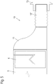
- Fig. 5 a second embodiment of an intake passage 10 in the same manner as Fig. 4 , Identical reference signs in this embodiment denote the same or equivalent elements as in the first embodiment.
- the in Fig. 5 shown intake duct 10 could instead of the previously shown in the in Fig. 1 and 2 Dishwasher 1 shown are used.
- the second portion 12 'of the intake duct 10 formed by suitable choice of material and a wave shape of its walls elastic, so that it can be varied without cutting within a certain range in its length can. It is noted that also in this embodiment, filters analogous to the filters 14 according to FIG Fig. 4 can be used.
- FIG. 6 an inventive operating method of the dishwasher 1 is shown.
- the dishwasher 1 corresponds to the in Fig. 1 shown here and is here in the same way as in Fig. 1 played.
- the air return flow 31 can be used to remove impurities that have settled on the heat exchanger 6.
- Such a cleaning step is advantageously completed in those sections of a cleaning program of the dishwasher 1, in which the heat pump is not operated.
- the cleaning step is carried out with an air return flow 31, whose volume flow density at the filter is increased in relation to the regular air flow 30.
- One possibility for achieving an increased volume flow density is an increase in the volume flow through the fan 7.
- the fan 7 can then be operated at a higher speed, for example in the cleaning step in the other direction of rotation.
- FIG. 7a to 7c An alternative or in addition to increasing the speed usable way to increase the volume flow density in the cleaning step is in the Fig. 7a to 7c shown.
- the figures show a development of the intake duct 10 of Fig. 4 in different operating states.
- two pivotable air guiding flaps 15 extending over the entire width of the second section 12 are arranged in the second section 12 of the intake duct 10.
- One of the louvers 15 has its pivot axis in the upper region of the second section 12, the other in the lower region. Both pivot axes are seen in the direction of the (regular) air flow 30 at the rear of the louvers 15.
- louvers 15 are placed parallel to each other and parallel to the air flow 30, so that they do not affect the air flow substantially.
- the louvers 15 are pivoted toward each other, as in the Fig. 7a-c is shown.
- the cross section of the air return flow 31 will be corresponding reduced, so that a compressed air return stream 31 'is passed to the filter 14, through which the filter 14 is effectively cleaned.
- the louvers 15 are pivoted synchronously. Snapshots of such a sequence are in the 7a-c played.
- the filter surface can be covered in this way one or more times from the compressed air return flow 31 '.
Landscapes
- Washing And Drying Of Tableware (AREA)
Abstract
Description
- Die Erfindung betrifft eine Geschirrspülmaschine, insbesondere eine Haushalts-Geschirrspülmaschine, zur Reinigung von Spülgut in einem Spülraum, aufweisend einen Wärmepumpenkreislauf mit einem Wärmetauscher und einen Ventilator zur Erzeugung eines Luftstroms, der durch den Wärmetauscher führt, wobei ein Luftauslass für den Luftstrom in einem Sockel der Geschirrspülmaschine angeordnet ist.
- Zur Senkung des Energieverbrauchs von Geschirrspülmaschinen ist der Einsatz von Wärmepumpen bekannt. Beispielsweise beschreibt die Druckschrift
EP 2 682 038 A2 eine Geschirrspülmaschine mit einer Luft-Wasser-Wärmepumpe, die Energie aus der Umgebungsluft entnimmt, um energieintensive Schritte des Spülprogramms, z.B. ein Aufheizen von Spülflüssigkeit, zu unterstützen. Dabei ist in einem Sockel der Geschirrspülmaschine ein Luftkanal mit einem Ventilator ausgebildet, in dem ein Wärmetauscher eines Verdampfers des Wärmepumpenkreislaufs angeordnet ist. Durch den Verdampfer wird der vorbeigeführten Luft Wärme entzogen. Es ist vorgesehen, einen Lufteinlass an der vorderen Seite des Sockels der Geschirrspülmaschine zu positionieren, wobei ein Luftauslass im hinteren Bereich des Sockels nach hinten oder zu einer Seite vorgesehen ist. - Häufig werden Geschirrspülmaschinen in eine Küchenzeile eingebaut, wobei die Küchenzeile nach hinten entweder an eine Raumwand angrenzt oder durch eine Rückwand begrenzt ist. Im hinteren Bereich des Sockels ausgelassene Luft strömt somit zwangsläufig zu einer oder beiden Seiten weg, wobei die Gefahr besteht, dass sie wieder nach vorne in den Ansaugbereich des Lufteinlasses strömt. Auf diese Weise könnte abgekühlte Luft wieder in den Luftkanal gelangen, wodurch die Effizient der Wärmepumpe sinkt.
- Der Sockel der Geschirrspülmaschine befindet sich zudem in der Regel hinter einer Sockelleiste der Küchenfront. In diesem Bereich unter den Küchenschränken und Einbaugeräten sammelt sich üblicherweise Hausstaub, der durch den Lufteinlass eingesaugt wird und den Wärmetauscher des Verdampfers zusetzen kann.
- Es ist daher eine Aufgabe der vorliegenden Erfindung, eine Geschirrspülmaschine der eingangs genannten Art bereit zu stellen, bei der die Gefahr eines Eintritts von abgekühlter Luft, die bereits durch den Wärmetauscher geführt wurde, und von stark staubbelasteter Luft verringert ist. Es ist eine weitere Aufgabe, ein Betriebsverfahren mit diesen Vorteilen für eine Geschirrspülmaschine zu schaffen.
- Diese Aufgabe wird gelöst durch eine Geschirrspülmaschine und ein Betriebsverfahren mit den Merkmalen des jeweiligen unabhängigen Anspruchs. Vorteilhafte Ausgestaltungen und Weiterbildungen sind Gegenstand der abhängigen Ansprüche.
- Eine erfindungsgemäße Geschirrspülmaschine der eingangs genannten Art zeichnet sich dadurch aus, dass der Luftkanal mit einem Ansaugkanal gekoppelt ist, der mit einer Lufteinlassöffnung über eine Vorderseite des Sockels hinausragt. So wird erreicht, dass Luft nicht unmittelbar im Sockelbereich angesaugt wird. Bei Luft, die nicht unmittelbar aus dem Sockelbereich angesaugt wird, ist die Wahrscheinlichkeit verringert, von dem Luftkanal abgegebene und somit bereits abgekühlte Luft unmittelbar wieder einzusaugen. Entsprechend steigt die Energieeffizienz der Wärmepumpe.
- Bevorzugt ragt der Ansaugkanal so weit über die Vorderseite des Sockels hinaus, dass er durch einen Ausschnitt einer Sockelleiste geführt werden kann oder geführt ist. Luft wird dann aus dem Küchenraum angesaugt und nicht aus dem von der Sockelleiste abgeteilten Bereich unter den Schränken oder Geräten der Küchenzeile. Auch die Staubbelastung ist im Küchenbereich geringer als unter der Küchenzeile, wodurch ein Zusetzen des Wärmetauschers mit Hausstaub verhindert oder zumindest verlangsamt wird. Der Ansaugkanal kann dabei eine Blende umfassen oder mit einer Blende gekoppelt sein, die in den Ausschnitt einer Sockelleiste einsetzbar ist.
- In einer vorteilhaften Ausgestaltung der Geschirrspülmaschine weist die Lufteinlassöffnung des Ansaugkanals einen flachen und rechteckförmigen Querschnitt auf. Bevorzugt erstreckt sich die Lufteinlassöffnung im Wesentlichen über eine gesamte Breite der Geschirrspülmaschine. Sie hat dadurch auch bei einer geringen Höhe, die sich gut in der Sockelleiste unterbringen lässt, eine ausreichend große Querschnittsfläche, die die Größe eines Luftstroms durch den Luftkanal nicht nachteilig beeinträchtigt.
- Weiter bevorzugt ist der Ansaugkanal zweiteilig aufgebaut und weist zwei Abschnitte auf. Mit einem ersten Abschnitt ist der Ansaugkanal mit dem Luftkanal gekoppelt. Ein zweiter Abschnitt ist an einer Seite mit dem ersten Abschnitt gekoppelt und weist an der gegenüberliegenden Seite die Lufteinlassöffnung auf. Bevorzugt hat der zweite Abschnitt einen über seine Länge gleichen Querschnitt. Dadurch kann er in beliebiger Länge abgelängt werden, um den Ansaugkanal an verschiede Einbausituationen anzupassen. Um das Ablängen zu vereinfachen ist der zweite Abschnitt bevorzugt aus einem leicht ablängbaren Material hergestellt, insbesondere einem weichen Kunststoff. Alternativ kann der zweite Abschnitt durch sein Material und/oder seine Formgebung in seiner Länge verändert werden, beispielsweise indem er als ein Falten- oder Wellenbalg ausgebildet ist. So kann - zumindest innerhalb bestimmter Längenbereiche - an die Einbausituation angepasst werden, ohne Werkzeuge zu verwenden.
- In einer weiteren vorteilhaften Ausgestaltung der Geschirrspülmaschine ist in dem Ansaugkanal und/oder der Blende mindestens ein Filter angeordnet. Der Filter verhindert zusätzlich ein Zusetzen des Wärmetauschers.
- Ein erfindungsgemäßes Betriebsverfahren ist geeignet für eine Geschirrspülmaschine mit einem Wärmepumpenkreislauf mit einem Wärmetauscher, der zusammen mit einem Ventilator in einem Luftkanal angeordnet ist, wobei der Luftkanal mit einem Ansaugkanal gekoppelt ist, der eine Lufteinlassöffnung aufweist. Durch die Lufteinlassöffnung wird in einem regulären Betrieb des Wärmepumpenkreislaufs Luft mithilfe des Ventilators eingesaugt, die dann in dem Wärmetauscher Wärme abgibt. Das Verfahren zeichnet sich dadurch aus, dass in einem Reinigungsschritt, den man auch als Wärmetauscher- und/oder Filter-Reinigungsschritt bezeichnen kann, der Ventilator so betrieben wird, dass Luft durch den Wärmetauscher aus der Lufteinlassöffnung ausgeblasen wird, um den Wärmetauscher oder einen dem Wärmetauscher zugeordneten Filter zu reinigen. Das Verfahren stellt somit einen Reinigungsschritt für den Wärmetauscher oder einen Filter bereit, indem Verunreinigungen durch einen Luftrückstrom entfernt werden können. Eine Abnahme der Energieeffizienz der Wärmepumpe kann so verhindert werden bzw. es können Standzeiten des Filters erhöht werden.
- Ein solcher Reinigungsschritt wird vorteilhaft in solchen Abschnitten eines Reinigungsprogramms der Geschirrspülmaschine absolviert, in denen die Wärmepumpe nicht betrieben wird. Vorteilhaft wird der Reinigungsschritt mit einem Luftrückstrom durchgeführt, dessen Volumenstromdichte am Filter gegenüber dem regulären Luftstrom erhöht ist.
- In einer vorteilhaften Ausgestaltung des Verfahrens wird der Ventilator in dem Reinigungsschritt gegenüber dem regulären Betrieb mit umgekehrter Drehrichtung und mit einer erhöhten Drehzahl betrieben. Für diese Weiterbildung des Verfahrens werden besonders vorteilhaft außer Steuerungsmitteln für die Drehrichtungsumkehr und die Drehzahl des Ventilators keine zusätzlichen Komponenten benötigt.
- In einer weiteren vorteilhaften Ausgestaltung des Verfahrens sind in dem Ansaugkanal Luftleitmittel angeordnet, um Luft gezielt auf Teilbereiche eines Filters zu lenken. Die Luftleitmittel können beispielsweise zwei unabhängig voneinander verschwenkbare Luftleitklappen umfassen. Während des Reinigungsschritts können so Teilbereiche des Filters gezielt mit einem gerichteten und so verstärkten Luftstrom gereinigt werden. Bevorzugt überstreicht der verstärkte Luftstrom in dem Reinigungsschritt ein- oder mehrmals die gesamte Filterfläche, um den Filter zu reinigen.
- Die Erfindung wird nachfolgend anhand eines Ausführungsbeispiels mithilfe von Figuren näher erläutert. Die Figuren zeigen:
- Fig. 1
- eine schematische Schnittdarstellung einer Geschirrspülmaschine, die unter einer Küchen-Arbeitsplatte eingebaut ist;
- Fig. 2
- die Geschirrspülmaschine gemäß
Fig. 1 in einer Vorderansicht; - Fig. 3
- eine schematische Vertikalschnittdarstellung eines Luftkanals mit einem Ansaugkanal in einem ersten Ausführungsbeispiel;
- Fig. 4
- der Luftkanal des ersten Ausführungsbeispiels, dargestellt in einem Horizontalschnitt;
- Fig. 5
- eine schematische Schnittdarstellung eines Wärmetauschers mit einem Ansaugkanal in einem zweiten Ausführungsbeispiel;
- Fig. 6
- eine schematische Schnittdarstellung der Geschirrspülmaschine der
Fig. 1 während eines erfindungsgemäßen Betriebsverfahrens; und - Fig. 7a-c
- jeweils eine schematische Schnittdarstellung eines Wärmetauschers mit einem Ansaugkanal der Geschirrspülmaschine nach
Fig. 6 in verschiedenen Stadien des Betriebsverfahrens. - In
Fig. 1 ist eine Geschirrspülmaschine 1 in einem schematischen Schnittbild dargestellt. Der Schnitt ist in einer vertikalen Ebene ausgeführt, die senkrecht zu einer Front 21 der Geschirrspülmaschine 1 verläuft. - Die Geschirrspülmaschine 1 weist einen Spülraum 2 auf, in den Spülgut eingeräumt werden kann und in dem Spülflüssigkeit zur Reinigung des Spülguts versprüht wird. Beispielhaft sind zwei Spülgutträger 3 mit Spülgut dargestellt. Zum Versprühen der Spülflüssigkeit sind beispielsweise rotierende Sprüharme vorhanden, die aus Gründen der Übersichtlichkeit hier nicht gezeigt sind. Vom Spülgut oder Wänden des Spülraums 2 abtropfende Spülflüssigkeit sammelt sich in einem Spülsumpf in einem unteren Bereich des Spülraums 2. Von dort wird die Spülflüssigkeit über eine Umwälzpumpe mit Druck beaufschlagt wieder im Spülraum 2 zur Reinigung eingesetzt, wodurch ein Spülkreislauf gebildet ist. Ein Sammeltopf des Spülsumpfs ist ebenso wie die Umwälzpumpe in einem Sockel 4 der Geschirrspülmaschine 1 unterhalb des Spülraums 2 angeordnet.
- Die Geschirrspülmaschine 1 ist in einem eingebauten Zustand unterhalb einer (Küchen-) Arbeitsplatte 20 dargestellt. Der Spülraum 2 der Geschirrspülmaschine 1 ist von vorne über eine schwenkbare Tür zugänglich, auf die die (Möbel-) Front 21 aufgesetzt ist, um der Küchenzeile, in die die Geschirrspülmaschine 1 eingebaut ist, ein einheitliches Erscheinungsbild zu geben. Unterhalb der Front 21 und dieser gegenüber ohne Beschränkung der Allgemeinheit leicht zurückversetzt verläuft eine Sockelleiste 22. Diese erstreckt sich in der Regel entlang der gesamten Küchenzeile, in die die Geschirrspülmaschine 1 eingebaut ist.
- Der Sockel 4 weist die gleiche Breite auf, die die Geschirrspülmaschine 1 auch im oberen Bereich hat. Auch nach hinten kann der Sockel ebenso weit reichen wie die Geschirrspülmaschine 1 im Bereich ihres Spülraums 2. Im vorderen Bereich ist der Sockel gegenüber dem Spülraum 2 nach hinten zurückversetzt. In den entstehenden Freiraum schwenkt typischerweise eine untere Kante der Tür der Geschirrspülmaschine 1 bzw. der daraufgesetzten Front 21 ein.
- Im Sockel 4 verläuft von vorne nach hinten ein Luftkanal 5, in dem ein Wärmetauscher 6 eines Verdampfers und ein Ventilator 7 angeordnet sind. Der Verdampfer ist Teil eines weiter nicht dargestellten Wärmepumpenkreislaufs, durch den Wärme aus der Umgebung, insbesondere der Umgebungsluft, also der Raumluft aus dem Aufstellungsraum der Geschirrspülmaschine, aufgenommen wird und zum Aufheizen der Spülflüssigkeit eingesetzt wird.
- Nach vorne ist dem Luftkanal 5 ein Ansaugkanal 10 vorgesetzt, der vorliegend zweiteilig ausgebildet ist und einen ersten Abschnitt 11 und einen zweiten Abschnitt 12 aufweist. Der zweite Abschnitt 12 geht in eine Blende 13 über, die in eine Öffnung in der Sockelleiste 22 eingesetzt ist.
- In der
Fig. 1 verdeutlichen Pfeile und Strömungslinien einen sich im Betrieb des Ventilators 7 einstellenden Luftstrom 30. Luft wird im Bereich vor der Geschirrspülmaschine 1 angesaugt und gelangt durch die Blende 13 und eine Lufteinlassöffnung in den Ansaugkanal 10, der sie in den den Luftkanal 5 leitet. Im dargestellten Beispiel ist der Ventilator 7 dem Wärmetauscher 6 im Luftstrom 30 nachgeordnet. Eine umgekehrte Anordnung von Ventilator 7 und Wärmetauscher 6 ist ebenso möglich. - Wieder abgegeben wird die angesaugte Luft in einem hinteren Bereich des Luftkanals 5, etwa entweder nach hinten oder zur Seite. Das Ansaugen der Luft aus einem Bereich vor der Sockelleiste 22 verhindert dabei, dass die vom Luftkanal 5 abgegebene Luft unmittelbar wieder in den Ansaugkanal 10 eingesogen werden kann. Zudem ist die vor der Sockelleiste 22 eingesogene Luft in der Regel weniger staubbelastet als Luft hinter der Sockelleiste 22, also aus einem Bereich unter den Küchenschränken, in dem nicht gesaugt oder gewischt werden kann und sich folglich Hausstaub im Laufe der Zeit ansammelt.
-
Fig. 2 zeigt die Geschirrspülmaschine 1 derFig. 1 in einer Draufsicht auf die Vorderseite. Sich seitlich anschließende Geräte und/oder Küchenschränke sind nicht wiedergegeben. In der Figur ist gut die sich in der Breite über die im Wesentlichen gesamte Breite der Geschirrspülmaschine 1 erstreckende Blende 13 zu erkennen, die die Lufteinlassöffnung des Ansaugkanals 10 definiert. In der Höhe nimmt die Blende 13 etwa die untere Hälfte der Sockelleiste 22 ein. Die Höhe der Sockelleiste 22 hängt von der Montagehöhe der Arbeitsplatte 20 ab. Bei geringerer Montagehöhe der Arbeitsplatte 20 kann die Sockelleiste im oberen Bereich gekürzt sein. - Der Querschnitt des Wärmetauschers 6 ist gestrichelt eingezeichnet. Er ist weniger breit als der Ansaugkanal 10, dafür höher. Dieses ist dem zur Verfügung stehenden Einbauraum im Sockel 4 geschuldet. Im Sockel 4 ist zentral der zuvor genannte Sammeltopf für die Spülflüssigkeit positioniert, so dass der Wärmetauscher 6 nur in einem Seitenbereich Platz findet.
-
Fig. 3 zeigt einen Horizontalschnitt durch die Anordnung aus Luftkanal 5, Ansaugkanal 10 und Blende 13. In dieser Darstellung ist zu erkennen, dass sich der Luftkanal 5 aus den genannten Platzgründen nach hinten zwischen dem Wärmetauscher 6 und dem Ventilator 7 verschmälert. - In
Fig. 4 ist ein Vertikalschnitt durch die Anordnung aus Luftkanal 5, Ansaugkanal 10 und Blende 13 dargestellt. Hier ist die Vergrößerung des Querschnitts in vertikaler Richtung zu erkennen. Die Höhe des Querschnitts ist zunächst im zweiten Abschnitt 12 des Ansaugkanals 10 gleichbleibend und vergrößert sich dann innerhalb des ersten Abschnitts 11 auf die Höhe des Luftkanals 5. Die gesamte Höhenaufweitung erfolgt also innerhalb des ersten Abschnitts 11. Am Übergang zwischen den beiden Abschnitten 11 und 12 hat der zweite Abschnitt 12 den gleichen Querschnitt wie am Übergang zur Blende 13. - Diese zweiteilige Ausbildung des Ansaugkanals 10 ist vorteilhaft, um den Ansaugkanal 10 in seiner Länge an unterschiedliche Abstände zwischen der vorderen Seite des Sockels 4 und der Sockelleiste 22 anzupassen. Dieser Abstand variiert mit der Einbausituation der Geschirrspülmaschine 1 und hängt von der Größe des Rücksprungs zwischen der Front 21 und der Sockelleiste 22 ab. Diese Größe wiederum ist u.a. von den in der Küchenzeile eingebauten Schränken und Geräten abhängig. Aufgrund des gleichbleibenden Querschnitts des zweiten Abschnitts 12 kann dessen Länge verändert werden und an den Abstand zwischen der vorderen Seite des Sockels 4 und der Sockelleiste 22 angepasst werden, ohne dass das die Blende 13 und die Größe des Ausschnitts in der Sockelleiste 22, in den die Blende 13 eingesetzt ist, beeinflussst.
- Um alle üblicherweise auftretenden Einbausituationen abdecken zu können, steht der Ansaugkanal 10 in seiner maximalen Länge bevorzugt um bis zu 100 mm (Millimetern) nach vorne über den Sockel 4 hervor. Die Höhe des zweiten Abschnitts 12 (und damit der Lufteinlassöffnung) liegt bevorzugt zwischen 25 und 40 mm. In der Breite erstreckt sich der zweite Abschnitt 12 und damit die Lufteinlassöffnung bevorzugt über die im Wesentlichen gesamte Breite der Geschirrspülmaschine 1 von in der Regel knapp 600 mm. Die Querschnittsfläche der Lufteinlassöffnung ist bevorzugt größer gewählt als die Querschnittsfläche des Wärmetauschers 6, so dass der Ansaugkanal 10 den maximalen Luftstrom durch den Luftkanal 5 nicht beeinträchtigt. Falls ein Filter 14 verwendet wird, ist bevorzugt die Querschnittsfläche der Lufteinlassöffnung so gewählt, dass sie größer ist als die doppelte Querschnittsfläche des Wärmetauschers 6, um den Einfluss eines Strömungswiderstands des Filters 14 möglichst klein zu halten. Die angegebene bevorzugte Höhe des zweiten Abschnitts 12 zwischen 25 und 40 mm führt dann zu einer Querschnittsfläche der Lufteinlassöffnung von 150 cm2 (Quadratzentimetern) bis zu 240 cm2.
- Zur Reinigung der angesaugten Luft kann ein Filter 14 oder können mehrere Filter 14 in dem Luftstrom 30 angeordnet sein. Dieser kann bzw. diese können insbesondere als Flächen- oder als Tiefenfilter ausgeführt sein.
Fig. 4 zeigt eine Mehrzahl alternativer Positionen für den oder die Filter 14. Der Filter 14 kann in der Blende 13 und in dem ersten und/oder zweiten Abschnitt 11, 12 des Ansaugkanals 10 eingesetzt sein. Zur Erzielung einer größeren Filterfläche kann ein etwa als Flächenfilter ausgebildeter Filter 14 gegenüber dem Luftstrom 30 schräg gestellt und/oder gewölbt oder plissiert sein. Durch den oder die Filter 14 wird ein Zusetzen des Wärmetauschers 6 weiter verhindert. - Zur Variation der Länge des zweiten Abschnitts 12 kann dieser zum einen in unterschiedlichen Längen vorgehalten werden. Alternativ oder zusätzlich kann der zweite Abschnitt 12 aus einem leicht ablängbaren und/oder flexiblem Material hergestellt sein, beispielsweise einem weichen Kunststoff.
-
Fig. 5 ein zweites Ausführungsbeispiel eines Ansaugkanals 10 in gleicher Darstellungsart wieFig. 4 . Gleiche Bezugszeichen kennzeichnen in dieser Ausgestaltung gleiche oder gleich wirkende Elemente wie beim ersten Ausführungsbeispiel. Der inFig. 5 gezeigte Ansaugkanals 10 könnte anstelle des zuvor gezeigten in der in denFig. 1 und2 gezeigten Geschirrspülmaschine 1 eingesetzt werden. - Bei dem Ausführungsbeispiel der
Fig. 5 ist der zweite Abschnitt 12' des Ansaugkanals 10 durch geeignete Materialwahl und eine Wellenformgebung seiner Wandungen elastisch ausgebildet, so dass er ohne Ablängen innerhalb eines bestimmten Bereichs in seiner Länge variiert werden kann. Es wird angemerkt, dass auch bei diesem Ausführungsbeispiel Filter analog zu den Filtern 14 gemäßFig. 4 verwendet werden können. - In
Fig. 6 ist ein erfindungsgemäßes Betriebsverfahren der Geschirrspülmaschine 1 dargestellt. Die Geschirrspülmaschine 1 entspricht der inFig. 1 gezeigten und ist hier in gleicher Weise wie inFig. 1 wiedergegeben. - Im Unterschied zu dem regulären Betrieb der Wärmepumpe wird in dem in
Fig. 6 gezeigten Zustand der Ventilator 7 mit umgekehrter Laufrichtung betrieben, so dass ein Luftrückstrom 31 von hinten nach vorne durch den Luftkanal 5 und den Ansaugkanal 10 führt. Durch den Luftrückstrom 31 werden Verunreinigungen, die sich auf dem Filter 14 abgesetzt haben, entfernt und wieder in den Raum geblasen. In einer Ausgestaltung der Geschirrspülmaschine 1, in der kein Filter 14 eingesetzt wird, kann der Luftrückstrom 31 eingesetzt werden, um Verunreinigungen zu entfernen, die sich auf dem Wärmetauscher 6 abgesetzt haben. - Ein derartiger Reinigungsschritt wird vorteilhaft in solchen Abschnitten eines Reinigungsprogramms der Geschirrspülmaschine 1 absolviert, in denen die Wärmepumpe nicht betrieben wird. Vorteilhaft wird der Reinigungsschritt mit einem Luftrückstrom 31 durchgeführt, dessen Volumenstromdichte am Filter gegenüber dem regulären Luftstrom 30 erhöht ist. Eine Möglichkeit zur Erzielung einer erhöhten Volumenstromdichte stellt eine Erhöhung des Volumenstroms durch den Ventilator 7 dar. Der Ventilator 7 kann dann beispielsweise in dem Reinigungsschritt in der anderen Drehrichtung mit einer höheren Drehzahl betrieben werden.
- Eine alternativ oder zusätzlich zur Drehzahlerhöhung einsetzbare Möglichkeit zur Erhöhung der Volumenstromdichte im Reinigungsschritt ist in den
Fig. 7a bis 7c dargestellt. Die Figuren zeigen eine Weiterbildung des Ansaugkanals 10 derFig. 4 in verschiedenen Betriebszuständen. Bei dieser Weiterbildung sind in dem zweiten Abschnitt 12 des Ansaugkanals 10 zwei sich über die gesamte Breite des zweiten Abschnitts 12 erstreckende schwenkbare Luftleitklappen 15 angeordnet. Eine der Luftleitklappen 15 hat ihre Schwenkachse im oberen Bereich des zweiten Abschnitts 12, die andere im unteren Bereich. Beide Schwenkachsen liegen in Richtung des (regulären) Luftstroms 30 gesehen hinten an den Luftleitklappen 15. - In einem regulären Betrieb der Wärmepumpe sind die Luftleitklappen 15 parallel zueinander und parallel zum Luftstrom 30 gestellt, so dass sie den Luftstrom im Wesentlichen nicht beeinflussen.
- Während des Reinigungsschritts werden die Luftleitklappen 15 aufeinander zu geschwenkt, wie in den
Fig. 7a-c dargestellt ist. Der Querschnitt des Luftrückstroms 31 wird entsprechend verkleinert, so dass ein verdichteter Luftrückstrom 31' auf den Filter 14 geleitet wird, durch den der Filter 14 effektiv gereinigt wird. Um mit dem verdichteten Luftrückstrom 31' die gesamte Filteroberfläche zu erreichen, werden die Luftleitklappen 15 synchron verschwenkt. Momentaufnahmen einer solchen Abfolge sind in denFig.7a-c wiedergegeben. Innerhalb eines Reinigungsschritts kann die Filteroberfläche auf diese Art ein- oder mehrfach von dem verdichteten Luftrückstrom 31' überstrichen werden. -
- 1
- Geschirrspülmaschine
- 2
- Spülraum
- 3
- Spülgutträger
- 4
- Sockel
- 5
- Luftkanal
- 6
- Wärmetauscher
- 7
- Ventilator
- 10
- Ansaugkanal
- 11
- erster Abschnitt
- 12
- zweiter Abschnitt
- 12'
- flexibler zweiter Abschnitt
- 13
- Blende
- 14
- Filter
- 15
- Luftleitklappe
- 20
- Arbeitsplatte
- 21
- Front
- 22
- Sockelleiste
- 30
- Luftstrom
- 31
- Luftrückstrom
- 31'
- verdichteter Luftrückstrom
Claims (15)
- Geschirrspülmaschine (1) zur Reinigung von Spülgut in einem Spülraum (2), aufweisend einen Wärmepumpenkreislauf mit einem Wärmetauscher (6), der zusammen mit einem Ventilator (7) in einem Luftkanal (5) angeordnet ist, wobei der Luftkanal (5) einen Luftauslass aufweist, der in einem Sockel (4) der Geschirrspülmaschine angeordnet ist, dadurch gekennzeichnet, dass der Luftkanal (5) mit einem Ansaugkanal (10) gekoppelt ist, der mit einer Lufteinlassöffnung über eine Vorderseite des Sockels (4) hinausragt.
- Geschirrspülmaschine (1) nach Anspruch 1, bei der der Ansaugkanal (10) so weit über die Vorderseite des Sockels (4) hinausragt, dass er durch einen Ausschnitt einer Sockelleiste (22) geführt werden kann.
- Geschirrspülmaschine (1) nach Anspruch 1 oder 2, bei der der Ansaugkanal (10) eine Blende (13) umfasst, die in den Ausschnitt einer Sockelleiste (22) einsetzbar ist.
- Geschirrspülmaschine (1) nach einem der Ansprüche 1 bis 3, bei der die Lufteinlassöffnung des Ansaugkanals (10) einen flachen und rechteckförmigen Querschnitt aufweist.
- Geschirrspülmaschine (1) nach einem der Ansprüche 1 bis 4, bei der sich die Lufteinlassöffnung im Wesentlichen über eine gesamte Breite der Geschirrspülmaschine (1) erstreckt.
- Geschirrspülmaschine (1) nach einem der Ansprüche 1 bis 5, bei der der Ansaugkanal (10) zwei Abschnitte (11, 12) aufweist, einen ersten Abschnitt (11), mit dem der Ansaugkanal (10) mit dem Luftkanal (5) gekoppelt ist, und einen zweiten Abschnitt (12, 12'), der an einer Seite mit dem ersten Abschnitt (11) gekoppelt ist und der an der gegenüberliegenden Seite die Lufteinlassöffnung aufweist.
- Geschirrspülmaschine (1) nach Anspruch 6, bei der der zweite Abschnitt (12, 12') einen über seine Länge gleichen Querschnitt aufweist.
- Geschirrspülmaschine (1) nach einem der Ansprüche 6 oder 7, bei der der zweite Abschnitt (12) aus einem leicht ablängbaren Material hergestellt ist, insbesondere einem weichen Kunststoff.
- Geschirrspülmaschine (1) nach einem der Ansprüche 6 bis 8, bei der der zweite Abschnitt (12') durch sein Material und/oder seine Formgebung in seiner Länge verändert werden kann,
und/oder bei der der zweite Abschnitt (12') ein Falten- oder Wellenbalg ist. - Geschirrspülmaschine (1) nach einem der Ansprüche 1 bis 9, bei der in dem Ansaugkanal (10) und/oder der Blende (13) mindestens ein Filter (14) angeordnet ist.
- Geschirrspülmaschine (1) nach Anspruch 10, bei in dem Ansaugkanal (10) Luftleitmittel angeordnet sind, um Luft gezielt auf Teilbereiche des Filters (14) zu lenken.
- Geschirrspülmaschine (1) nach Anspruch 11, bei in dem die Luftleitmittel zwei unabhängig voneinander verschwenkbare Luftleitklappen (15) umfassen.
- Verfahren zum Betreiben einer Geschirrspülmaschine (1) mit einen Wärmepumpenkreislauf mit einem Wärmetauscher (6), der zusammen mit einem Ventilator (7) in einem Luftkanal (5) angeordnet ist, wobei der Luftkanal (5) mit einem Ansaugkanal (10) mit einer Lufteinlassöffnung gekoppelt ist, dadurch gekennzeichnet, dass in einem Reinigungsschritt der Ventilator (7) so betrieben wird, dass Luft durch den Wärmetauscher (6) aus der Lufteinlassöffnung ausgeblasen wird, um den Wärmetauscher (6) oder einen dem Wärmetauscher (6) zugeordneten Filter (14) zu reinigen.
- Verfahren nach Anspruch 13, bei dem der Reinigungsschritt ausgeführt wird, wenn der Wärmepumpenkreislauf nicht aktiv ist.
- Verfahren nach Anspruch 13 oder 14, bei dem der Ventilator (7) in dem Reinigungsschritt gegenüber einem Normalbetriebszustand mit umgekehrter Drehrichtung und/oder mit einer erhöhten Drehzahl betrieben wird.
Priority Applications (1)
| Application Number | Priority Date | Filing Date | Title |
|---|---|---|---|
| PL18181564T PL3427628T3 (pl) | 2017-07-12 | 2018-07-04 | Zmywarka do naczyń |
Applications Claiming Priority (1)
| Application Number | Priority Date | Filing Date | Title |
|---|---|---|---|
| DE102017115580 | 2017-07-12 |
Publications (2)
| Publication Number | Publication Date |
|---|---|
| EP3427628A1 true EP3427628A1 (de) | 2019-01-16 |
| EP3427628B1 EP3427628B1 (de) | 2020-03-04 |
Family
ID=62873179
Family Applications (1)
| Application Number | Title | Priority Date | Filing Date |
|---|---|---|---|
| EP18181564.8A Active EP3427628B1 (de) | 2017-07-12 | 2018-07-04 | Geschirrspülmaschine |
Country Status (3)
| Country | Link |
|---|---|
| EP (1) | EP3427628B1 (de) |
| ES (1) | ES2781320T3 (de) |
| PL (1) | PL3427628T3 (de) |
Cited By (3)
| Publication number | Priority date | Publication date | Assignee | Title |
|---|---|---|---|---|
| EP3718459A1 (de) | 2019-04-04 | 2020-10-07 | Miele & Cie. KG | Geschirrspülmaschine, insbesondere haushaltsgeschirrspülmaschine |
| WO2023057203A1 (de) * | 2021-10-04 | 2023-04-13 | BSH Hausgeräte GmbH | Geschirrspülmaschine mit zumindest einer ein sorbens umfassenden trocknungseinheit |
| EP4298980A1 (de) | 2022-06-30 | 2024-01-03 | Arçelik Anonim Sirketi | Wärmepumpengeschirrspüler |
Families Citing this family (1)
| Publication number | Priority date | Publication date | Assignee | Title |
|---|---|---|---|---|
| CN114305282A (zh) * | 2020-09-30 | 2022-04-12 | 博西华电器(江苏)有限公司 | 家用洗碗机 |
Citations (4)
| Publication number | Priority date | Publication date | Assignee | Title |
|---|---|---|---|---|
| DE8915941U1 (de) * | 1989-01-17 | 1992-04-16 | AEG Hausgeräte GmbH, 90429 Nürnberg | Geschirrspülmaschine mit Entlüftungsöffnung |
| DE10347244A1 (de) * | 2003-03-06 | 2004-02-26 | Konrad, Hilmar, Dipl.-Ing. | Spülmaschine |
| EP1721559A1 (de) * | 2005-05-10 | 2006-11-15 | Electrolux Home Products Corporation N.V. | Geschirrspüler |
| EP2682038A2 (de) | 2012-07-03 | 2014-01-08 | Miele & Cie. KG | Geschirrspülmaschine und Verfahren zum Betreiben einer Geschirrspülmaschine |
-
2018
- 2018-07-04 EP EP18181564.8A patent/EP3427628B1/de active Active
- 2018-07-04 ES ES18181564T patent/ES2781320T3/es active Active
- 2018-07-04 PL PL18181564T patent/PL3427628T3/pl unknown
Patent Citations (4)
| Publication number | Priority date | Publication date | Assignee | Title |
|---|---|---|---|---|
| DE8915941U1 (de) * | 1989-01-17 | 1992-04-16 | AEG Hausgeräte GmbH, 90429 Nürnberg | Geschirrspülmaschine mit Entlüftungsöffnung |
| DE10347244A1 (de) * | 2003-03-06 | 2004-02-26 | Konrad, Hilmar, Dipl.-Ing. | Spülmaschine |
| EP1721559A1 (de) * | 2005-05-10 | 2006-11-15 | Electrolux Home Products Corporation N.V. | Geschirrspüler |
| EP2682038A2 (de) | 2012-07-03 | 2014-01-08 | Miele & Cie. KG | Geschirrspülmaschine und Verfahren zum Betreiben einer Geschirrspülmaschine |
Cited By (4)
| Publication number | Priority date | Publication date | Assignee | Title |
|---|---|---|---|---|
| EP3718459A1 (de) | 2019-04-04 | 2020-10-07 | Miele & Cie. KG | Geschirrspülmaschine, insbesondere haushaltsgeschirrspülmaschine |
| DE102019108883A1 (de) * | 2019-04-04 | 2020-10-08 | Miele & Cie. Kg | Geschirrspülmaschine, insbesondere Haushaltsgeschirrspülmaschine |
| WO2023057203A1 (de) * | 2021-10-04 | 2023-04-13 | BSH Hausgeräte GmbH | Geschirrspülmaschine mit zumindest einer ein sorbens umfassenden trocknungseinheit |
| EP4298980A1 (de) | 2022-06-30 | 2024-01-03 | Arçelik Anonim Sirketi | Wärmepumpengeschirrspüler |
Also Published As
| Publication number | Publication date |
|---|---|
| EP3427628B1 (de) | 2020-03-04 |
| ES2781320T3 (es) | 2020-09-01 |
| PL3427628T3 (pl) | 2020-06-15 |
Similar Documents
| Publication | Publication Date | Title |
|---|---|---|
| EP3427628B1 (de) | Geschirrspülmaschine | |
| EP1708606B1 (de) | Betriebsphasenabhängige steuerung einer einrichtung zur wärmerückgewinnung an durchlaufgeschirrspülautomaten | |
| DE102006012217B4 (de) | Geschirrspüler mit Gegen-Konvektionsluftstrom | |
| DE102007019298B4 (de) | Geschirrspüler | |
| EP1708607B1 (de) | Geschirrspülautomat mit regelbarer wärmerückgewinnung | |
| EP3775700B1 (de) | Dunstabzugsvorrichtung mit filtervorrichtung | |
| DE102012105902A1 (de) | Geschirrspülmaschine und Verfahren zum Betreiben einer Geschirrspülmaschine | |
| DE102007008826A1 (de) | Gewerbliche Geschirrspülmaschine und Verfahren zu ihrem Betrieb | |
| DE102007008827A1 (de) | Gewerbliche Geschirrspülmaschine | |
| EP2449945A2 (de) | Haushaltgerät mit Wärmepumpe am Prozesswasserkreislauf | |
| EP3127463B1 (de) | Geschirrspülmaschine mit einem luftkanal | |
| DE102007006787A1 (de) | Reinigungssystem für Wärmerückgewinnung | |
| DE102011083179B4 (de) | Transportspülmaschine und Verfahren zum Betreiben einer Transportspülmaschine | |
| EP3718459B1 (de) | Geschirrspülmaschine, insbesondere haushaltsgeschirrspülmaschine | |
| DE102017115585B4 (de) | Geschirrspülmaschine und Verfahren zum Betreiben einer Geschirrspülmaschine | |
| DE3515592C2 (de) | ||
| WO2020078705A2 (de) | Haushalts-geschirrspülmaschine mit einem selbstreinigenden filtersystem | |
| DE102019100002A1 (de) | Anordnung einer Geschirrspülmaschine mit Wärmepumpenkreislauf und Unterbauzubehör | |
| EP0378836A1 (de) | Geschirrspülmaschine mit Entlüftungsöffnung | |
| DE102015105060A1 (de) | Reinigungsgerät, insbesondere Staubsauger oder Vorsatzgerät eines Staubsaugers | |
| WO2012076434A2 (de) | Kältegerät mit zwangsgekühltem wärmetauscher | |
| DE102010001840B4 (de) | Haushaltsgerät | |
| DE102020212345A1 (de) | Haushaltsgeschirrspülmaschine mit zumindest einem Luftauslass | |
| DE29900414U1 (de) | Kühlgerät mit verbessertem Führungselement für den Wärmeabfuhrluftstrom | |
| EP4221556A1 (de) | Haushaltsgeschirrspülmaschine mit zumindest einem luftauslass |
Legal Events
| Date | Code | Title | Description |
|---|---|---|---|
| PUAI | Public reference made under article 153(3) epc to a published international application that has entered the european phase |
Free format text: ORIGINAL CODE: 0009012 |
|
| STAA | Information on the status of an ep patent application or granted ep patent |
Free format text: STATUS: THE APPLICATION HAS BEEN PUBLISHED |
|
| AK | Designated contracting states |
Kind code of ref document: A1 Designated state(s): AL AT BE BG CH CY CZ DE DK EE ES FI FR GB GR HR HU IE IS IT LI LT LU LV MC MK MT NL NO PL PT RO RS SE SI SK SM TR |
|
| AX | Request for extension of the european patent |
Extension state: BA ME |
|
| STAA | Information on the status of an ep patent application or granted ep patent |
Free format text: STATUS: REQUEST FOR EXAMINATION WAS MADE |
|
| 17P | Request for examination filed |
Effective date: 20190716 |
|
| RBV | Designated contracting states (corrected) |
Designated state(s): AL AT BE BG CH CY CZ DE DK EE ES FI FR GB GR HR HU IE IS IT LI LT LU LV MC MK MT NL NO PL PT RO RS SE SI SK SM TR |
|
| RIC1 | Information provided on ipc code assigned before grant |
Ipc: A47L 15/48 20060101ALI20190823BHEP Ipc: A47L 15/42 20060101ALI20190823BHEP Ipc: A47L 15/00 20060101AFI20190823BHEP |
|
| GRAP | Despatch of communication of intention to grant a patent |
Free format text: ORIGINAL CODE: EPIDOSNIGR1 |
|
| STAA | Information on the status of an ep patent application or granted ep patent |
Free format text: STATUS: GRANT OF PATENT IS INTENDED |
|
| INTG | Intention to grant announced |
Effective date: 20191106 |
|
| GRAS | Grant fee paid |
Free format text: ORIGINAL CODE: EPIDOSNIGR3 |
|
| GRAA | (expected) grant |
Free format text: ORIGINAL CODE: 0009210 |
|
| STAA | Information on the status of an ep patent application or granted ep patent |
Free format text: STATUS: THE PATENT HAS BEEN GRANTED |
|
| REG | Reference to a national code |
Ref country code: DE Ref legal event code: R084 Ref document number: 502018000880 Country of ref document: DE |
|
| AK | Designated contracting states |
Kind code of ref document: B1 Designated state(s): AL AT BE BG CH CY CZ DE DK EE ES FI FR GB GR HR HU IE IS IT LI LT LU LV MC MK MT NL NO PL PT RO RS SE SI SK SM TR |
|
| REG | Reference to a national code |
Ref country code: GB Ref legal event code: FG4D Free format text: NOT ENGLISH |
|
| REG | Reference to a national code |
Ref country code: CH Ref legal event code: EP |
|
| REG | Reference to a national code |
Ref country code: AT Ref legal event code: REF Ref document number: 1239437 Country of ref document: AT Kind code of ref document: T Effective date: 20200315 |
|
| REG | Reference to a national code |
Ref country code: DE Ref legal event code: R096 Ref document number: 502018000880 Country of ref document: DE |
|
| REG | Reference to a national code |
Ref country code: IE Ref legal event code: FG4D Free format text: LANGUAGE OF EP DOCUMENT: GERMAN |
|
| REG | Reference to a national code |
Ref country code: ES Ref legal event code: GC2A Effective date: 20200408 |
|
| REG | Reference to a national code |
Ref country code: GB Ref legal event code: 746 Effective date: 20200331 |
|
| PG25 | Lapsed in a contracting state [announced via postgrant information from national office to epo] |
Ref country code: RS Free format text: LAPSE BECAUSE OF FAILURE TO SUBMIT A TRANSLATION OF THE DESCRIPTION OR TO PAY THE FEE WITHIN THE PRESCRIBED TIME-LIMIT Effective date: 20200304 Ref country code: NO Free format text: LAPSE BECAUSE OF FAILURE TO SUBMIT A TRANSLATION OF THE DESCRIPTION OR TO PAY THE FEE WITHIN THE PRESCRIBED TIME-LIMIT Effective date: 20200604 Ref country code: FI Free format text: LAPSE BECAUSE OF FAILURE TO SUBMIT A TRANSLATION OF THE DESCRIPTION OR TO PAY THE FEE WITHIN THE PRESCRIBED TIME-LIMIT Effective date: 20200304 |
|
| REG | Reference to a national code |
Ref country code: NL Ref legal event code: MP Effective date: 20200304 |
|
| PG25 | Lapsed in a contracting state [announced via postgrant information from national office to epo] |
Ref country code: HR Free format text: LAPSE BECAUSE OF FAILURE TO SUBMIT A TRANSLATION OF THE DESCRIPTION OR TO PAY THE FEE WITHIN THE PRESCRIBED TIME-LIMIT Effective date: 20200304 Ref country code: LV Free format text: LAPSE BECAUSE OF FAILURE TO SUBMIT A TRANSLATION OF THE DESCRIPTION OR TO PAY THE FEE WITHIN THE PRESCRIBED TIME-LIMIT Effective date: 20200304 Ref country code: SE Free format text: LAPSE BECAUSE OF FAILURE TO SUBMIT A TRANSLATION OF THE DESCRIPTION OR TO PAY THE FEE WITHIN THE PRESCRIBED TIME-LIMIT Effective date: 20200304 Ref country code: GR Free format text: LAPSE BECAUSE OF FAILURE TO SUBMIT A TRANSLATION OF THE DESCRIPTION OR TO PAY THE FEE WITHIN THE PRESCRIBED TIME-LIMIT Effective date: 20200605 Ref country code: BG Free format text: LAPSE BECAUSE OF FAILURE TO SUBMIT A TRANSLATION OF THE DESCRIPTION OR TO PAY THE FEE WITHIN THE PRESCRIBED TIME-LIMIT Effective date: 20200604 |
|
| REG | Reference to a national code |
Ref country code: ES Ref legal event code: FG2A Ref document number: 2781320 Country of ref document: ES Kind code of ref document: T3 Effective date: 20200901 |
|
| REG | Reference to a national code |
Ref country code: LT Ref legal event code: MG4D |
|
| PG25 | Lapsed in a contracting state [announced via postgrant information from national office to epo] |
Ref country code: NL Free format text: LAPSE BECAUSE OF FAILURE TO SUBMIT A TRANSLATION OF THE DESCRIPTION OR TO PAY THE FEE WITHIN THE PRESCRIBED TIME-LIMIT Effective date: 20200304 |
|
| PG25 | Lapsed in a contracting state [announced via postgrant information from national office to epo] |
Ref country code: IS Free format text: LAPSE BECAUSE OF FAILURE TO SUBMIT A TRANSLATION OF THE DESCRIPTION OR TO PAY THE FEE WITHIN THE PRESCRIBED TIME-LIMIT Effective date: 20200704 Ref country code: RO Free format text: LAPSE BECAUSE OF FAILURE TO SUBMIT A TRANSLATION OF THE DESCRIPTION OR TO PAY THE FEE WITHIN THE PRESCRIBED TIME-LIMIT Effective date: 20200304 Ref country code: LT Free format text: LAPSE BECAUSE OF FAILURE TO SUBMIT A TRANSLATION OF THE DESCRIPTION OR TO PAY THE FEE WITHIN THE PRESCRIBED TIME-LIMIT Effective date: 20200304 Ref country code: CZ Free format text: LAPSE BECAUSE OF FAILURE TO SUBMIT A TRANSLATION OF THE DESCRIPTION OR TO PAY THE FEE WITHIN THE PRESCRIBED TIME-LIMIT Effective date: 20200304 Ref country code: SM Free format text: LAPSE BECAUSE OF FAILURE TO SUBMIT A TRANSLATION OF THE DESCRIPTION OR TO PAY THE FEE WITHIN THE PRESCRIBED TIME-LIMIT Effective date: 20200304 Ref country code: PT Free format text: LAPSE BECAUSE OF FAILURE TO SUBMIT A TRANSLATION OF THE DESCRIPTION OR TO PAY THE FEE WITHIN THE PRESCRIBED TIME-LIMIT Effective date: 20200729 Ref country code: EE Free format text: LAPSE BECAUSE OF FAILURE TO SUBMIT A TRANSLATION OF THE DESCRIPTION OR TO PAY THE FEE WITHIN THE PRESCRIBED TIME-LIMIT Effective date: 20200304 Ref country code: SK Free format text: LAPSE BECAUSE OF FAILURE TO SUBMIT A TRANSLATION OF THE DESCRIPTION OR TO PAY THE FEE WITHIN THE PRESCRIBED TIME-LIMIT Effective date: 20200304 |
|
| REG | Reference to a national code |
Ref country code: DE Ref legal event code: R097 Ref document number: 502018000880 Country of ref document: DE |
|
| PLBE | No opposition filed within time limit |
Free format text: ORIGINAL CODE: 0009261 |
|
| STAA | Information on the status of an ep patent application or granted ep patent |
Free format text: STATUS: NO OPPOSITION FILED WITHIN TIME LIMIT |
|
| PG25 | Lapsed in a contracting state [announced via postgrant information from national office to epo] |
Ref country code: DK Free format text: LAPSE BECAUSE OF FAILURE TO SUBMIT A TRANSLATION OF THE DESCRIPTION OR TO PAY THE FEE WITHIN THE PRESCRIBED TIME-LIMIT Effective date: 20200304 |
|
| 26N | No opposition filed |
Effective date: 20201207 |
|
| PG25 | Lapsed in a contracting state [announced via postgrant information from national office to epo] |
Ref country code: MC Free format text: LAPSE BECAUSE OF FAILURE TO SUBMIT A TRANSLATION OF THE DESCRIPTION OR TO PAY THE FEE WITHIN THE PRESCRIBED TIME-LIMIT Effective date: 20200304 Ref country code: SI Free format text: LAPSE BECAUSE OF FAILURE TO SUBMIT A TRANSLATION OF THE DESCRIPTION OR TO PAY THE FEE WITHIN THE PRESCRIBED TIME-LIMIT Effective date: 20200304 |
|
| REG | Reference to a national code |
Ref country code: BE Ref legal event code: MM Effective date: 20200731 |
|
| PG25 | Lapsed in a contracting state [announced via postgrant information from national office to epo] |
Ref country code: LU Free format text: LAPSE BECAUSE OF NON-PAYMENT OF DUE FEES Effective date: 20200704 Ref country code: IE Free format text: LAPSE BECAUSE OF NON-PAYMENT OF DUE FEES Effective date: 20200704 |
|
| PG25 | Lapsed in a contracting state [announced via postgrant information from national office to epo] |
Ref country code: BE Free format text: LAPSE BECAUSE OF NON-PAYMENT OF DUE FEES Effective date: 20200731 |
|
| REG | Reference to a national code |
Ref country code: CH Ref legal event code: PL |
|
| PG25 | Lapsed in a contracting state [announced via postgrant information from national office to epo] |
Ref country code: LI Free format text: LAPSE BECAUSE OF NON-PAYMENT OF DUE FEES Effective date: 20210731 Ref country code: CH Free format text: LAPSE BECAUSE OF NON-PAYMENT OF DUE FEES Effective date: 20210731 |
|
| PG25 | Lapsed in a contracting state [announced via postgrant information from national office to epo] |
Ref country code: MT Free format text: LAPSE BECAUSE OF FAILURE TO SUBMIT A TRANSLATION OF THE DESCRIPTION OR TO PAY THE FEE WITHIN THE PRESCRIBED TIME-LIMIT Effective date: 20200304 Ref country code: CY Free format text: LAPSE BECAUSE OF FAILURE TO SUBMIT A TRANSLATION OF THE DESCRIPTION OR TO PAY THE FEE WITHIN THE PRESCRIBED TIME-LIMIT Effective date: 20200304 |
|
| PG25 | Lapsed in a contracting state [announced via postgrant information from national office to epo] |
Ref country code: MK Free format text: LAPSE BECAUSE OF FAILURE TO SUBMIT A TRANSLATION OF THE DESCRIPTION OR TO PAY THE FEE WITHIN THE PRESCRIBED TIME-LIMIT Effective date: 20200304 Ref country code: AL Free format text: LAPSE BECAUSE OF FAILURE TO SUBMIT A TRANSLATION OF THE DESCRIPTION OR TO PAY THE FEE WITHIN THE PRESCRIBED TIME-LIMIT Effective date: 20200304 |
|
| P01 | Opt-out of the competence of the unified patent court (upc) registered |
Effective date: 20230528 |
|
| PGFP | Annual fee paid to national office [announced via postgrant information from national office to epo] |
Ref country code: TR Payment date: 20230623 Year of fee payment: 6 Ref country code: PL Payment date: 20230614 Year of fee payment: 6 |
|
| PGFP | Annual fee paid to national office [announced via postgrant information from national office to epo] |
Ref country code: IT Payment date: 20230721 Year of fee payment: 6 Ref country code: GB Payment date: 20230725 Year of fee payment: 6 Ref country code: ES Payment date: 20230816 Year of fee payment: 6 |
|
| PGFP | Annual fee paid to national office [announced via postgrant information from national office to epo] |
Ref country code: FR Payment date: 20230725 Year of fee payment: 6 Ref country code: DE Payment date: 20230731 Year of fee payment: 6 |