EP3426592B1 - Verfahren zur erfassung der grösse einer auf einen hebemotor in einem materialförderungssystem ausgeübten last, verfahren zur bestimmung der grösse einer auf ein materialförderungssystem ausgeübten last, wenn die last mit mehreren hebemotoren angehoben wird und motorantrieb - Google Patents
Verfahren zur erfassung der grösse einer auf einen hebemotor in einem materialförderungssystem ausgeübten last, verfahren zur bestimmung der grösse einer auf ein materialförderungssystem ausgeübten last, wenn die last mit mehreren hebemotoren angehoben wird und motorantrieb Download PDFInfo
- Publication number
- EP3426592B1 EP3426592B1 EP17763723.8A EP17763723A EP3426592B1 EP 3426592 B1 EP3426592 B1 EP 3426592B1 EP 17763723 A EP17763723 A EP 17763723A EP 3426592 B1 EP3426592 B1 EP 3426592B1
- Authority
- EP
- European Patent Office
- Prior art keywords
- motor
- load
- speed
- parameter
- torque
- Prior art date
- Legal status (The legal status is an assumption and is not a legal conclusion. Google has not performed a legal analysis and makes no representation as to the accuracy of the status listed.)
- Active
Links
Images


Classifications
-
- B—PERFORMING OPERATIONS; TRANSPORTING
- B66—HOISTING; LIFTING; HAULING
- B66C—CRANES; LOAD-ENGAGING ELEMENTS OR DEVICES FOR CRANES, CAPSTANS, WINCHES, OR TACKLES
- B66C13/00—Other constructional features or details
- B66C13/16—Applications of indicating, registering, or weighing devices
-
- B—PERFORMING OPERATIONS; TRANSPORTING
- B66—HOISTING; LIFTING; HAULING
- B66C—CRANES; LOAD-ENGAGING ELEMENTS OR DEVICES FOR CRANES, CAPSTANS, WINCHES, OR TACKLES
- B66C15/00—Safety gear
-
- B—PERFORMING OPERATIONS; TRANSPORTING
- B66—HOISTING; LIFTING; HAULING
- B66C—CRANES; LOAD-ENGAGING ELEMENTS OR DEVICES FOR CRANES, CAPSTANS, WINCHES, OR TACKLES
- B66C17/00—Overhead travelling cranes comprising one or more substantially horizontal girders the ends of which are directly supported by wheels or rollers running on tracks carried by spaced supports
-
- G—PHYSICS
- G01—MEASURING; TESTING
- G01G—WEIGHING
- G01G19/00—Weighing apparatus or methods adapted for special purposes not provided for in the preceding groups
- G01G19/14—Weighing apparatus or methods adapted for special purposes not provided for in the preceding groups for weighing suspended loads
-
- G—PHYSICS
- G01—MEASURING; TESTING
- G01L—MEASURING FORCE, STRESS, TORQUE, WORK, MECHANICAL POWER, MECHANICAL EFFICIENCY, OR FLUID PRESSURE
- G01L1/00—Measuring force or stress, in general
- G01L1/005—Measuring force or stress, in general by electrical means and not provided for in G01L1/06 - G01L1/22
-
- G—PHYSICS
- G01—MEASURING; TESTING
- G01L—MEASURING FORCE, STRESS, TORQUE, WORK, MECHANICAL POWER, MECHANICAL EFFICIENCY, OR FLUID PRESSURE
- G01L3/00—Measuring torque, work, mechanical power, or mechanical efficiency, in general
-
- G—PHYSICS
- G01—MEASURING; TESTING
- G01L—MEASURING FORCE, STRESS, TORQUE, WORK, MECHANICAL POWER, MECHANICAL EFFICIENCY, OR FLUID PRESSURE
- G01L3/00—Measuring torque, work, mechanical power, or mechanical efficiency, in general
- G01L3/02—Rotary-transmission dynamometers
- G01L3/04—Rotary-transmission dynamometers wherein the torque-transmitting element comprises a torsionally-flexible shaft
-
- G—PHYSICS
- G01—MEASURING; TESTING
- G01L—MEASURING FORCE, STRESS, TORQUE, WORK, MECHANICAL POWER, MECHANICAL EFFICIENCY, OR FLUID PRESSURE
- G01L5/00—Apparatus for, or methods of, measuring force, work, mechanical power, or torque, specially adapted for specific purposes
-
- H—ELECTRICITY
- H02—GENERATION; CONVERSION OR DISTRIBUTION OF ELECTRIC POWER
- H02P—CONTROL OR REGULATION OF ELECTRIC MOTORS, ELECTRIC GENERATORS OR DYNAMO-ELECTRIC CONVERTERS; CONTROLLING TRANSFORMERS, REACTORS OR CHOKE COILS
- H02P23/00—Arrangements or methods for the control of AC motors characterised by a control method other than vector control
- H02P23/14—Estimation or adaptation of motor parameters, e.g. rotor time constant, flux, speed, current or voltage
-
- H—ELECTRICITY
- H02—GENERATION; CONVERSION OR DISTRIBUTION OF ELECTRIC POWER
- H02H—EMERGENCY PROTECTIVE CIRCUIT ARRANGEMENTS
- H02H7/00—Emergency protective circuit arrangements specially adapted for specific types of electric machines or apparatus or for sectionalised protection of cable or line systems, and effecting automatic switching in the event of an undesired change from normal working conditions
- H02H7/08—Emergency protective circuit arrangements specially adapted for specific types of electric machines or apparatus or for sectionalised protection of cable or line systems, and effecting automatic switching in the event of an undesired change from normal working conditions for dynamo-electric motors
- H02H7/085—Emergency protective circuit arrangements specially adapted for specific types of electric machines or apparatus or for sectionalised protection of cable or line systems, and effecting automatic switching in the event of an undesired change from normal working conditions for dynamo-electric motors against excessive load
- H02H7/0851—Emergency protective circuit arrangements specially adapted for specific types of electric machines or apparatus or for sectionalised protection of cable or line systems, and effecting automatic switching in the event of an undesired change from normal working conditions for dynamo-electric motors against excessive load for motors actuating a movable member between two end positions, e.g. detecting an end position or obstruction by overload signal
Definitions
- the subject matter disclosed herein relates to measuring the load in a material handling system. More specifically, the subject matter disclosed herein relates to a method and apparatus for measuring the load in a material handling system using one or more motor drives to lift a load, where each motor drive controls operation of a hoist motor.
- Material handling systems are widely used to lift heavy loads, weighing up to hundreds of tons.
- a typical material handling system includes at least one motor used to raise and lower the load and at least one additional motor to position the material handling system over the load to be moved.
- Common applications include manufacturing facilities, in which large components may be positioned for assembly and/or the final assembly may be moved for shipping. Further, material handling systems are often required to handle loads of varying sizes. It is known that electric motors are capable of producing rated torque up to rated speed. Therefore, it may be desirable to verify that the weight of the load the system is attempting to move is less than or equal to the rated capacity of the system, such that the operator may safely raise/lower and position the load.
- US2013/302113 discloses an example of a system and method for determining the load present in a material handling system.
- US2013/302113 discloses a method for detecting a magnitude of a load applied to a motor using a motor drive controlling the motor, comprising the steps of during a commissioning run, generating a table containing a plurality of values of a first signal internal to the motor drive corresponding to the load applied to the motor at a plurality of speeds of the motor; storing the table in a memory device in the motor drive; during subsequent runs, reading a value of the first signal internal to the motor drive corresponding to the load applied to the motor; reading a value of a second signal internal to the motor drive corresponding to the speed of the motor; reading a stored value of the first signal form the table, the stored value corresponding to the speed of the motor during the present run as indicated by the second signal; and comparing the value of the first signal during the present run to the stored value of the first signal.
- US2013/302113 also discloses a motor drive
- this weight measurement may be performed by the addition of an external weighing device, such as a load cell.
- external weighing devices have not been realized without certain disadvantages.
- External weighing devices add expense in both material and commissioning costs. They load cell is typically mounted to a mechanical component of the material handling system that is subject to a degree of strain or deflection as a result of lifting the load. Consequently, the load cell may need to be mounted on the hook or another movable member of the material handling system.
- the feedback signal from the load cell must then be wired or wirelessly communicated to a controller. The feedback signal may also need calibration to the load.
- weighing devices measure forces applied to the device.
- the force applied as a result of gravity acting on the load corresponds to the weight of the object; however, in a material handling system, other forces are similarly applied to the weighing device.
- the torque required to accelerate a load when raising the load or to decelerate a load when lowering the load provides an additive force on the weighing device.
- deceleration when raising or acceleration when lowering is assisted by gravity, resulting in a reduced weight being measured by the weighing device.
- the motor either raises and suspends the load at zero speed or operates for a short period at a constant speed when measuring the load.
- the weight of the load may vary as the load is raised or lowered.
- the variation in weight may be unexpected.
- containers are loaded and unloaded between storage facilities, trucks, trains, and ships.
- the containers are often stacked several layers high and in close proximity to each other or to walls, for example, within a hold of a ship.
- the container may sway, for example, due to the wind, or the other containers may move, for example, as the deck of a ship moves. In either instance, the container may contact or become snagged on an adjacent container, causing a change in the weight of the load.
- the variation in weight is part of the application requirements.
- bulk materials such as sand or salt may require a bucket, or clam shell, attachment.
- the clam-shell is lowered in an open position and closed to scoop up a load of the bulk material.
- the weight of the load may be significantly lower or even near zero during the period at which the load is measured. The load may, therefore, be initially determined as safe but may subsequently exceed the rated capacity of the material handling system.
- a load may require multiple hoists for lifting due, for example, to the weight and/or size of the load.
- a single bridge may include two or more hoists mounted to a single bridge.
- multiple bridges may be included on a single set of rails and each bridge includes a single hoist. In either application, multiple hoists may be utilized to lift the single load.
- each hoist When multiple hoists are used for lifting a load, the overall system load ratings must be considered. Although each hoist has a rated capacity, the bridge and rails also have load ratings which cannot be exceeded. When lifting a load with multiple hoists, each hoist may be operating within its rated capacity however the combined weight of the load on a single bridge or on a set of rails may exceed the load rating for the bridge or rails.
- the subject matter disclosed herein describes a method and apparatus for determining the load present in a material handling system.
- An improved system for determining the weight of a load applied to lifting apparatus of a hoist separates the weight of the load from the mechanics of the material handling system.
- the material handling system may include, for example, cabling, hook blocks, and the like which provide some load to the motor event when the hoist is in an unloaded state. Further, the cable weight varies as the hook block and a load, if attached, are raised and lowered.
- the drive train of the material handling system may also include a gearbox or other mechanical coupling through which the torque generated by the motor is transferred to the sheave. The mechanical inefficiencies of the drive train as well as the weight of the cabling and hook block require some level of torque to run a hoist even in an unloaded condition.
- the load weight detection system disclosed herein utilizes four measured operating conditions by which the weight of the load is determined.
- the hoist motor is run at a low speed and at rated speed with both no load and with rated load connected to the hoist.
- the level of torque generated by the motor under each of these four operating conditions is stored in parameters in the motor drive. Further, these four operating conditions are measured both for constant speed operation and during acceleration. When the motor is accelerating, the torque may be observed over a small window surrounding the desired speed or over a small window close to the actual speed. As a result, two sets of parameters are stored in the motor drive.
- the motor drive When the motor drive is controlling operation of the hoist motor, the motor drive utilizes the two sets of parameters to determine the weight of a load connected to the hoist.
- the motor drive When the motor drive is accelerating the speed of the motor, the motor drive utilizes the set of parameters which include the torque observed during acceleration of the motor under known conditions, and when the motor drive is operating at a constant or nearly constant speed, the motor drive utilizes the set of parameters which include the torque observed during constant speed operation of the motor.
- the motor drive receives a signal corresponding to the speed of the hoist motor. Using the appropriate set of parameters, the motor drive determines an expected torque at no load and at rated load for the measured speed. The motor drive also measures the torque output by the motor at the measured speed. Based on the measured torque, as well as the expected torque at no load and at rated load for the measured speed, the motor drive then determines the load present on the hoist.
- the material handling system may also include multiple hoists, where two or more hoists are required to operate in tandem to lift a load.
- Each motor drive determines the portion of the load supported by the respective hoist motor it is controlling by using, for example, the method of weight measurement discussed above.
- a first motor drive transmits the weight of the load as seen by that hoist motor to a second motor drive operating in tandem to lift the load.
- the second motor drive adds the weight of the load as seen by the second hoist motor to the weight received from the first motor drive.
- the second and then subsequent motor drives transmit the combined load to the next motor drive in the chain.
- the sum of the load as determined at that motor drive is compared to a rated load capacity for the material handling system. If the total load being lifted by the hoists exceeds the rated load capacity for the material handling system, a fault is set by the motor drive detecting the condition and the fault is transmitted to each of the motor drives operating in tandem to perform the lift.
- a method of detecting a magnitude of a load applied to a hoisting motor in a material handling system using a motor drive controlling the motor, according to the independent method claim 1 is provided.
- the motor drive may operate with either an open or closed loop on position feedback.
- the motor drive may use an internal speed reference signal to measure the speed of rotation of the hoisting motor, or a position feedback device may be operatively coupled to the hoisting motor and generate a signal corresponding to an angular position of the hoisting motor.
- the motor drive measures the speed of rotation of the hoisting motor as a function of the change in the signal corresponding to the angular position of the hoisting motor with respect to time.
- the motor drive stores a first set of parameters and a second set of parameters.
- Each of the first and second sets of parameters includes a first parameter, a second parameter, a third parameter, and a fourth parameter.
- the first set of parameters defines expected levels of torque produced by the motor while the motor is running at a constant speed at each of the first and second speeds
- the second set of parameters defines expected levels of torque produced by the motor while the motor is accelerating through or approaching each of the first and second speeds.
- the motor drive may execute one or more commissioning runs.
- a first run at the first speed with no load either a current or a torque output by the motor drive is measured.
- a second run at the second speed with no load either the current or the torque output by the motor drive is measured.
- a third run at the first speed with the rated load either the current or the torque output by the motor is measured.
- the fourth run at the second speed with the rated load either the current or the torque output by the motor drive is measured.
- a torque required by the motor is determined as a function of the measured current or torque.
- the torque required by the motor during each of the first, second, third, and fourth runs is stored in the first, second, third, and fourth parameters, respectively, of the first set of parameters.
- a fifth run between the first speed and the second speed with no load either the current or the torque output by the motor drive is measured.
- a sixth run between the first speed and the second speed with the rated load, either the current or the torque output by the motor drive is measured.
- the torque required by the motor while accelerating at about each of the first and second speeds is determined as a function of the measured current or torque.
- the torque required by the motor while accelerating at about each of the first and second speeds during the fifth run is stored in the first and second parameters, respectively, of the second set of parameters.
- the torque required by the motor while accelerating at about each of the first and second speeds during the sixth run is stored in the third and fourth parameters, respectively, of the second set of parameters.
- a motor drive for a hoisting motor according to the independent claim 10 is provided.
- a method of determining a magnitude of a load applied to a material handling system when the load is lifted using a plurality of hoisting motors and each hoisting motor is controlled by a separate motor drive, according to the method claim 8 is provided.
- the load applied to the material handling system may be lifted using at least three hoisting motors.
- a signal corresponding to the sum of the first and second loads applied to the material handling system may be transmitted from the second motor drive to a third motor drive, the third motor drive controlling a third hoisting motor selected from the plurality of hoisting motors.
- a load applied to the third hoisting motor is measured with the third motor drive, and the measured load applied to the third hoisting motor is converted to a third measured load applied to the material handling system.
- the third measured load applied to the material handling system is summed to the signal corresponding to the sum of the first and second loads applied to the material handling system in the third motor drive to determine the total load applied to the material handling system.
- the total load applied to the material handling system may be compared to a maximum load for the material handling system in the second motor drive, and a fault signal in the second motor drive may be generated when the total load applied to the material handling system is greater than the maximum load for the material handling system.
- an overload detection system for a material handling system including a plurality of hoisting motors to lift a load.
- the overload detection system includes a plurality of motor drives, where each motor drive is operatively connected to control operation of one of the plurality of hoisting motors.
- Each motor drive includes an input operable to receive a signal corresponding to a total weight of the load transmitted from one of the other motor drives, an output operable to transmit a new total weight of the load as determined by the motor drive, a memory device storing a plurality of instructions and a plurality of parameters, and a processor.
- the processor is operable to execute the plurality of instructions to measure a load applied to the hoisting motor operatively connected to the motor drive, convert the measured load applied to the hoisting motor to a measured load applied to the material handling system by the motor drive, add the measured load applied to the material handling system by the motor drive to the signal corresponding to the total weight of the load as received from one of the other motor drives to determine the new total weight of the load, and transmit the new total weight of the load from the output.
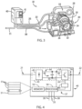
- the material handling system 1a includes two bridges 2. Each bridge 2 is configured to move in a first axis of motion 11 along a pair of rails 3 located at either end of the bridges 2.
- One of the illustrated bridges 2a includes a pair of trolleys 4, where each trolley 4 is configured to move along the bottom of the first bridge 2a in a second axis of motion 12, generally perpendicular to the first axis of motion 11 and along the length of the first bridge 2a.
- the second bridge 2b may include a single trolley 4 or multiple trolleys.
- One or more sheaves 5, also referred to as drums, may be mounted to each trolley 4, around which a cable 6 is wound.
- the sheave 5 may be rotated in either direction to wind or unwind the cable 6 around the sheave 5.
- the cable 6 is operatively connected to a hook block or any other lifting fixture 7 such that the hook block may be connected to a load, L, and move in a third axis of motion 13, generally perpendicular to each of the first and the second axes of motions, 11 and 12.
- One or more control cabinets housing, for example, motor controllers 40 (see e.g., Fig.
- an industrial controller such as a programmable logic controller (PLC)
- PLC programmable logic controller
- the wiring may consist of a festoon system 9, conductor bars, cables in a cable tray or any other suitable system for conducting power and control signals between the control cabinets and each trolley 4.
- the material handling system 1b may include a single bridge 2, where the bridge 2 is configured to move in a first axis of motion 11 along a pair of rails 3 located at either end of the bridge 2.
- a single trolley 4 is mounted on and configured to move along the top of the bridge 2 in a second axis of motion 12, generally perpendicular to the first axis of motion 11, along the length of the bridge 2. It is contemplated that multiple trolleys 4 may be mounted to the bridge 2.
- One or more control cabinets 8 housing, for example, the motor controllers 40 are mounted on the bridge 2 and wiring may be run between the motor controller (40) and the respective motor 20 (see e.g., Fig. 3 ) being controlled.
- the wiring may consist of a festoon system, conductor bars, cables in a cable tray or any other suitable system for conducting power and control signals between the control cabinets 8 and each device in the material handling system 1.
- the exemplary portion of the drive system 10 includes a motor 20 controlled by a motor controller 40, also referred to herein as a motor drive.
- the motor controller 40 delivers a regulated voltage and/or current to the motor 20 via a set of electrical conductors 22.
- the magnitude and/or frequency of the voltage or current may be varied to control the speed at which the motor 20 rotates, the torque produced by the motor 20, or a combination thereof.
- a feedback device 24, such as an encoder or a resolver, is connected to the motor, typically by mounting the feedback device 24 to the output shaft at one end of the motor 20.
- the feedback device 24 provides to the motor controller 40, via electrical conductors 26, any suitable electrical signal, corresponding to rotation of the motor 20, as would be known in the art.
- a gearbox 28 may be connected to the output shaft of the motor 20 for rotating any suitable drive member at a desired speed according to the requirements of the axis of motion to which the gearbox 28 is connected.
- the motor 20 may be configured to directly rotate the drive member.
- a braking unit 30 is supplied to prevent undesired rotation of the motor 20.
- the braking unit 30 includes a brake wheel 32 mounted to a shaft extending from the motor 20. Brake shoes 34 engage opposite sides of the brake wheel 32.
- a brake controller 36 selectively engages and disengages the brake shoes 34 to the brake wheel 32.
- the brake controller 36 may be, but is not limited to, an electric or a hydraulic controller receiving a command signal from the motor controller 40 via an electrical conductor 38.
- the braking unit 30 may include, for example, a disc attached to the motor and employee brake pads to engage the disc. It is contemplated that numerous other configurations of brakes may be employed without deviating from the scope of the present invention.
- the braking unit 30 may be connected at any suitable location along the drive system 10 to prevent motion of the commanded axis according to application requirements.
- the exemplary embodiments of material handling systems 1a, 1b illustrated in Figs. 1 and 2 are not intended to be limiting.
- the present invention may be incorporated into material handling systems 1 having numerous configurations or combinations of elements either illustrated in or in addition to those illustrated in Figs. 1 and 2 according to the application requirements without deviating from the scope of the invention.
- the trolleys may be under-hung, or top-mount.
- the material handling system may have a single bridge or multiple bridges. A single trolley or multiple trolleys may be mounted on each bridge. Each trolley may include a single hoist and hoist motor or multiple hoists and hoist motors.
- Different trolleys, bridges, and/or hoists may be configured to operate asynchronously, synchronously, or selectively operate either synchronously or asynchronously.
- the material handling systems may utilize load handling members, including but not limited to a block and hook, a bucket, a clam-shell attachment, or a magnet.
- the present invention may be incorporated into winch-type applications which may spool out and reel in a cable along a more horizontal plane, including but not limited to a winch, a dredge, an anchor, or other side-pull systems.
- the terms “raise” and “lower” are intended to denote the operations of letting out or reeling in a cable 6 connectable to a load handling member 7 of a material handling system 1 and are not limited to moving a load, L, in a vertical plane.
- the load handling member 7 may be any suitable device for connecting to or grabbing a load, including, but not limited to, a hook block, a bucket, a clam-shell, a grapple, or a magnet. While an overhead crane may lift a load vertically, a winch may pull a load from the side. Further, an appropriately configured load handling member 7 may allow a load to unwind cable or may reel in the load by winding up the cable at any desired angle between a horizontal plane and a vertical plane.
- the “cable,” also known as a “rope,” may be of any suitable material.
- the “cable” may be made from, but is not limited to, steel, nylon, plastic, other metal or synthetic materials, or a combination thereof, and may be in the form of a solid or stranded cable, chain links, or any other combination as is known in the art.
- a “run” is one cycle of operation of the motor controller 40.
- the motor controller 40 controls operation of the motor 20, rotating the motor 20 to cause the cable 6 to wind around or unwind from the sheave 5.
- a “run” may include multiple starts and stops of the motor 20 and, similarly it may require multiple “runs” to let the cable 6 fully unwind or wind completely around the sheave 5. Further, the cable 6 need not be fully unwound from or wound around the sheave 5 before reversing direction of rotation of the motor 20. In addition, direction of rotation of the motor 20 may be reversed within a single run,
- the motor controller 40 receives a command signal 25 from any suitable operator interface.
- the operator interface may be, but is not limited to, a keypad 41 mounted on the motor controller 40, a remote industrial joystick with a wired connection to the motor controller 40, or a radio receiver connected to the motor controller receiving a wireless signal from a corresponding radio transmitter.
- the motor controller 40 includes an input 21, for example, one or more terminals, configured to receive power, which may be a single or multiple phase alternating current (AC) or a direct current (DC) power source.
- a power conversion section 43 of the motor controller 40 converts the input power 21 to a desired power at an output 22 configured to connect to the motor 20.
- the output 22 is a power conversion section 43 of the motor controller 40 converts the input power 21 to a desired power at an output 22 configured to connect to the motor 20. The output 22.
- the power conversion section 43 includes a rectifier section 42 and an inverter section 46, converting a fixed AC input to a variable amplitude and variable frequency AC output.
- the rectifier section 42 is electrically connected to the power input 21.
- the rectifier section 42 may be either passive, such as a diode bridge, or active, including controlled power electronic devices such as transistors.
- the input power 21 is converted to a DC voltage present on a DC bus 44.
- the DC bus 44 may include a bus capacitance 48 connected across the DC bus 44 to smooth the level of the DC voltage present on the DC bus 44.
- the bus capacitance 48 may include a single or multiple capacitors arranged in serial, parallel, or a combination thereof according to the power ratings of the motor controller 40.
- An inverter section 46 converts the DC voltage on the DC bus 44 to the desired output power 22 for the motor 20 according to switching signals 62.
- the motor controller 40 further includes a processor 50 connected to a memory device 52. It is contemplated that the processor 50 may be a single processor or multiple processors operating in tandem. It is further contemplated that the processor 50 may be implemented in part or in whole on a field programmable gate array (FPGA), an application specific integrated circuit (ASIC), a logic circuit, or a combination thereof.
- the memory device 52 may be a single or multiple electronic devices, including static memory, dynamic memory, or a combination thereof.
- the memory device 52 preferably stores parameters 51 of the motor controller 40 and one or more programs, which include instructions executable on the processor 50. The parameters 51 may, for example, configure operation of the motor controller 40 or store data for later use by the motor controller 40.
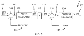
- the processor 50 is configured to execute a motor control module 100 to generate a voltage reference 122 to the motor 20 corresponding to the necessary amplitude and frequency to run the motor 20 and the desired speed reference 102.
- the motor 20 may include a position sensor 24 connected to the motor controller 40 via an electrical connection 26 to provide a position feedback signal corresponding to the angular position of the motor 20.
- the processor 50 determines a speed feedback signal 104 as a function of the rate of change of the position feedback signal over time.
- the processor 50 receives feedback signals, 55 and 57, from sensors, 54 and 56 respectively.
- the sensors, 54 and 56 may include one or more sensors generating signals, 55 and 57, corresponding to the amplitude of voltage and/or current present at the DC bus 44 or at the output 22 of the motor controller 40, respectively.
- the switching signals 62 may be determined by an application specific integrated circuit 60 receiving reference signals from a processor 50 or, optionally, directly by the processor 50 executing the stored instructions.
- the switching signals 62 are generated, for example, as a function of the feedback signals, 55 and 57, received at the processor 50.
- the processor 50 receives a command signal 25 indicating a desired operation of the corresponding motor 20 in the material handling system 1 and provides a variable amplitude and frequency output voltage 22 to the motor 20 responsive to the command signal 25.
- the command signal 25 is received by the processor 50 and converted, for example, from discrete digital signals or an analog signal to an appropriately scaled speed reference 102 for use by the motor control module 100. If closed loop operation of the motor drive 40 is desired, where closed loop operation includes a speed feedback signal 104, the speed reference 102 and the speed feedback signal 1 04 enter a summing junction 106, resulting in a speed error signal 107.
- the speed feedback signal 104 may be derived from a position feedback signal generated by the position sensor 24.
- the speed feedback signal 104 may be derived from an internally determined position signal generated, for example, by a position observer.
- the speed error signal 107 is provided as an input to a speed regulator 108.
- the speed regulator 108 determines the required torque reference 110 to minimize the speed error signal 107, thereby causing the motor 20 to run at the desired speed reference 102.
- the speed reference signal 102 may be scaled directly to a torque reference 110 that would result in the motor 20 operating at the desired speed reference 102.
- a scaling factor 112 converts the torque reference 110 to a desired current reference 114.
- the current reference 114 and a current feedback signal 116 enter a second summing junction 118, resulting in a current error signal 119.
- the current error signal is provided as an input to the current regulator 120.
- the current regulator 120 generates the voltage reference 122 which will minimize the error signal 119, again causing the motor 20 to run at the desired speed reference 102.
- This voltage reference 122 is used to generate the switching signals 62 which control the inverter section 46 to produce a variable amplitude and frequency output voltage 22 to the motor 20.
- the motor controller 40 may utilize current feedback signals 57 and/or reference signals, for example, the torque reference 110 to determine a level of torque produced by the motor 20.
- the torque produced by the motor is generally proportional to the current, or at least a portion thereof, output by the motor 20.
- a three-phase current may be converted by Park's transform to a torque producing component, also referred to as a q-axis current, and a flux producing component, also referred to as a d-axis current.
- the q-axis current is proportional to the torque produced by the motor and, therefore, may be used to determine a level of torque produced by the motor.
- any suitable internal reference or measured feedback signal that may be converted to a torque reference or torque feedback signal may be utilized to determine the level of torque being produced by the motor 20.
- the motor controller 40 may execute a number of commissioning runs to determine the values for each of the parameters 51 to be used during load weight measurement.
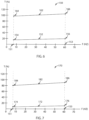
- An initial sequence of runs may be used to determine torque levels expected during constant speed operation of the motor 20.
- the hoist is initially operated in an unloaded condition. Although the hoist is unloaded, the hoist motor 20 still experiences some level of load.
- the hoist motor 20 must drive, for example, a gear box, a sheave connected to the output of the gear box (or connected to the motor if in a direct-drive configuration), the weight of the ropes wound around the sheave and the weight of a hook block connected to the end of the ropes. Thus, while the hoist is unloaded, the hoist motor 20 experiences some load.
- the hoist motor 20 is then run at a first speed in the unloaded condition.
- the first speed is at the low end of the expected range of operation for the motor 20 and may be, for example, between about two and ten hertz. Preferably, the first speed is set to about six hertz.
- Tire hoist motor 20 is then run at a second speed in the unloaded condition. The second speed is at the upper end of the expected range of operation of the motor 20 and may be, for example, at the rated speed of operation for the hoist motor 20.
- the motor controller 40 then executes another commissioning run again at each of the first and second speeds with the hoist having a rated load.
- the torque generated by the motor 20 during each of the commissioning runs may be stored in parameters 51 for later use to determine the weight of the load connected to the hoist.
- a first level of torque 174 produced by the motor 20 when running at the first speed 151 in an unloaded condition is stored in a first parameter 51 and a second level of torque 176 produced by the motor 20 when running at the second speed 153 in an unloaded condition is stored in a second parameter 51.
- a third level of torque 184 produced by the motor 20 when running at the first speed 151 in a loaded condition is stored in a third parameter 51 and a fourth level of torque 186 produced by the motor 20 when running at the second speed 153 in a loaded condition is stored in a fourth parameter 51.
- the motor controller 40 may execute a number of additional commissioning runs to monitor the torque generated by the motor during acceleration.
- the additional commissioning runs may be performed by accelerating from zero speed up to rated speed.
- the hoist motor 20 may start operating at any speed below the first speed and accelerate through the first speed.
- the hoist is initially operated in an unloaded condition.
- the motor controller 40 monitors the torque.
- a user configurable range of speeds may be defined around the first speed for which the motor controller 40 monitors the torque, and an average value of the torque during this speed range may be stored. The motor 20 continues to accelerate up to the second speed.
- the motor controller 40 will typically decelerate the motor 20 as it approaches rated speed and continue operating at rated speed.
- the motor controller 40 may be configured to accelerate through rated speed when operating in an unloaded condition.
- a user configurable range of speeds may be defined around the second speed for which the motor controller 40 monitors the torque, and an average value of the torque during this speed range may be stored.
- the motor controller 40 may monitor the torque over a speed range less than the second speed and prior to beginning to decelerate to the second speed.
- the speed range may be defined from about fifty-four hertz to about fifty-seven hertz.
- the motor controller 40 monitors the torque for acceleration throughout the second speed range prior to decelerating the motor, and an average value of the torque during this speed range may be stored. If the second speed selected for the constant speed was less than rated speed, the motor controller 40 may utilize either method of monitoring torque, that is, monitoring for a range of speeds defined around the second speed or monitoring for a range of speeds prior to decelerating to the second speed. The motor controller 40 then executes another commissioning run again at each of the first and second speeds with the hoist having a rated load.
- the torque generated by the motor 20 during each of the commissioning runs may be stored in parameters 51 for later use to determine the weight of the load connected to the hoist.
- a first level of torque 154 produced by the motor 20 when accelerating through the first speed 151 in an unloaded condition is stored in a first parameter 51 and a second level of torque 156 produced by the motor 20 when accelerating through or approaching the second speed 153 in an unloaded condition is stored in a second parameter 51.
- a third level of torque 164 produced by the motor 20 when accelerating through the first speed 151 in a loaded condition is stored in a third parameter 51 and a fourth level of torque 166 produced by the motor 20 when accelerating through or approaching the second speed 153 in a loaded condition is stored in a fourth parameter 51.
- the motor controller 40 stores two sets of parameters, where one set of parameters includes torque values expected when the motor 20 is operating at constant speed and the second set of parameters includes torque values expected when the motor is accelerating.
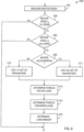
- the processor 50 of the motor controller 40 executes a weight measurement module 200, according to one embodiment of the invention, to determine the weight of the load present on the hoist.
- the motor controller 40 measures the motor speed. If the motor controller 40 is operating in a closed loop manner, the speed may be determined from the position feedback signal generated by the position sensor 24. If the motor controller 40 is operating in an open loop manner, the speed may be determined, for example, from a speed observer generating an estimated speed of the motor 20 or, optionally, by using a speed reference signal.
- the motor speed is compared to the first speed 151.
- the motor 20 is not operating fast enough and the motor controller 40 jumps to the end of the weight measurement module 200. If the motor speed is greater than or equal to the first speed 151, the motor speed is than compared to the second speed 153, as shown in step 206. If the motor speed is greater than the second speed 153, the motor controller 40 again jumps to the end of the weight measurement module 200.
- the weight measurement module 200 determines the weight of the load present on the hoist. As seen in step 208, the weight measurement module 200 first determines whether the motor controller 40 is accelerating or operating at a steady speed. If the motor controller is running at constant speed, the weight measurement module 200 uses the first set of parameters 51, as discussed above, which include torque values expected when the motor 20 is operating at constant speed, as shown in step 210. If the motor controller 40 is commanding the motor 20 to accelerate, the weight measurement module 200 uses the second set of parameters 51, as discussed above, which include torque values expected when the motor 20 is accelerating, as shown in step 212.
- the weight measurement module 200 determines the torque expected at no load based on the speed at which the motor 20 is operating. If the motor 20 is running at constant speed, the motor controller 40 reads the first torque value 174 and the second torque value 176 from the first set parameters, and if the motor 20 is accelerating, the motor controller 40 reads the first torque value 154 and the second torque value 156 from the second set parameters. The weight measurement module 200 then interpolates between the first and second torque values to determine an expected torque at the speed at which the motor is operating. As shown in Figs. 6 and 7 , a first set of torque values 172 results when the motor is running at constant speed and a second set of torque values 152 results when the motor is accelerating. The motor controller 40 selects the torque value from among the respective set of torque values 172, 152 that corresponds to the speed at which the motor is running.
- the weight measurement module 200 similarly determines the torque expected at rated load based on the speed at which the motor 20 is operating. If the motor 20 is running at constant speed, the motor controller 40 reads the third torque value 184 and the fourth torque value 186 from the first set parameters, and if the motor 20 is accelerating, the motor controller 40 reads the third torque value 164 and the fourth torque value 166 from the second set parameters. The weight measurement module 200 then interpolates between the third and fourth torque values to determine an expected torque at the speed at which the motor is operating. As shown in Figs. 6 and 7 , a third set of torque values 182 results when the motor is running at constant speed and a fourth set of torque values 162 results when the motor is accelerating. The motor controller 40 selects the torque value from among the respective set of torque values 182, 162 that corresponds to the speed at which the motor is running.
- the weight measurement module 200 uses the sets of torque values 152, 162, 172, 182 determined in the prior steps to determine the weight of the load present on the hoist.
- the motor controller 40 determines the level of torque presently being generated by the motor 20.
- the weight measurement module 200 determines where the present level of torque falls between the level of torque expected at no load (i.e., zero percent) and at rated load (i.e., one hundred percent) for the current speed of operation to determine what percent of load is present on the hoist system.
- the motor controller 40 compensates for the torque required to control the mechanics of the hoist motor 20 and associated drive train and determines a load weight for just the load connected to the hoist. Further, the motor controller 40 is configured to execute the weight measurement module 200 at a periodic interval. Within each periodic interval, the weight measurement module 200 is executed once and a new load weight is determined. Thus, if the weight of the load changes during the run, the motor controller 40 is able to detect the change.
- a single bridge 2 may include multiple trolleys 4, where each trolley 4 includes a hoist.
- a first trolley 4 may be positioned near one end of the load, L, and a second trolley 4 may be positioned near the other end of the load, L.
- a sling, spreader bar, or other lifting member may be connected to each hook 7 and around the load, L. The hoists on each trolley 4 are operated in tandem to lift the load, L.
- a hoist on a trolley 4 of a first bridge 2 and another hoist on a trolley 4 of a second bridge 2 may each be positioned proximate one end of a load, L, and each hoist, trolley 4, and bridge 2 operated in tandem to move the load, L.
- both the rated capacity of the hoist as well as the rated capacity of the material handling system 1 must be considered. If, for example, a bridge 2 includes two trolleys 4 and two hoists, one of the hoists may be configured to lift a load up to the rated load of the bridge 2. The other of the hoists may be configured to lift a load up to one-half the rated load of the bridge 2. In this manner, the bridge has the flexibility to lift up to its rated capacity either with a single hoist or with both hoists operating in tandem.
- the bridge 2 may be rated to lift a load up to one hundred tons.
- the first hoist may similarly be rated to lift a load up to one hundred tons, and the second hoist may be rated to lift a load up to fifty tons.
- each hoist's individual load check functions are suitable to detect an overload of the material handling system 1.
- the load seen by the fifty ton hoist will exceed fifty tons and its load check function can detect the overload condition.
- the one hundred ton hoist may lift, for example, seventy tons and the fifty ton hoist may lift forty-five tons.
- Each hoist is within its rated capacity; however, the total load is one hundred fifteen tons, exceeding the rated capacity for the bridge 2.
- FIG. 9 an exemplary arrangement of multiple motor drives 40, each controlling a different hoist motor 20, for use in a multiple hoist lifting operation is configured to detect the total weight of the load.
- three motor drives 40a, 40b, 40n are illustrated, it is contemplated that any number of motor drives 40 may be configured to operate in tandem to lift a load.
- Each additional motor drive 40 could be inserted between the second motor drive 40b and the last motor drive 40n and wired in a manner similar to the second motor drive 40b.
- Each motor drive 40 receives an input signal 250 to enable total system weight measurement.
- a contact 252 may be controlled by a separate system controller that enables/disables the total system weight measurement, allowing the function to run, for example, only when a multiple hoist lift is being performed.
- the motor drive 40 may be configured to always execute total system weight measurement.
- Each motor drive 40 determines the weight of the load being lifted by the hoist and corresponding hoist motor 20 being controlled by the motor drive 40. It is contemplated that each motor drive 40 utilizes the load weight measurement system and method as discussed in detail above.
- each motor drive 40 may utilized other load weight measurement systems and/or methods to determine the weight of the load present on the motor 20 being controlled by the motor drive 40.
- the motor drives 40 are further configured to utilize the various load weights measured by each motor drive 40 to determine a total weight of the load present on the material handling system 1.
- Each motor drive 40 outputs a cumulative load weight signal 255.
- One of the motor drives 40 is selected as a first motor drive, and according to the illustrated embodiment in Fig. 9 , motor drive 40a is the first motor drive. Because motor drive 40a is the first motor drive, it receives no load measurement information from other motor drives 40. Consequently, the first motor drive 40a outputs just the weight of the load present on the motor 20 being controlled by the motor drive 40 as the cumulative load weight signal 255.
- the cumulative load weight signal 255 from the first motor drive 40a is then provided as an input to the second motor drive 40b.
- the second motor drive 40b adds the load weight from the first motor drive 40a to the load weight determined by the second motor drive 40b to determine a cumulative load weight for the load being lifted.
- the second motor drive 40b similarly transmits the newly determined value of the load as a cumulative load weight signal 255 from the second motor drive 40b to the next motor drive 40 in the chain.
- Each motor drive 40 is similarly connected to the next motor drive 40 in a daisy chain configuration, and each motor drive 40 participating in the tandem lift adds the load weight for its respective motor 20 to the cumulative load weight signal 255 as it is passed through the motor drive 40.
- the weight of the load detected on the corresponding motor 20 controlled by the last motor drive 40n is added to the cumulative load weight signal to arrive at a total weight of the load being lifted by the motor drives 40.
- various combinations of motor drives 40 may be selected for participation in a tandem lift.
- one motor drive 40 may be designated as the first motor drive 40a, this is from a wiring perspective only and does not indicate that the first motor drive 40a need to be involved in all tandem lifts. It simply indicates that the first motor drive 40a will always output a cumulative load weight equal to the weight of the load seen by the corresponding motor 20 controlled by the first motor drive 40a. If, for example, the first motor drive 40a is not being used in a tandem lift, the portion of the load seen by the corresponding motor 20 controlled by the first motor drive 40a will be zero. The first motor drive 40a will, therefore, output a cumulative load weight signal 255 of zero to the second motor drive 40b. If the second motor drive 40b is participating in the tandem lift, the second motor drive 40b will then add the weight of the load seen by its corresponding motor 20 to zero and, therefore, output this weight as the new cumulative load weight signal 225.
- each motor drive 40 must covert the weight of the load seen by its corresponding motor 20 into a weight scaled to the weight of the material handling system 1. If the measured load in each motor drive 40 is determined as a percentage of rated load, as illustrated in Figs. 6 and 7 , this measured load is a percentage of the rated load for the corresponding motor drive 40. It is contemplated that the rated load for the material handling system 1 may be stored in a parameter 51 of each motor drive 40 and read from memory 52 for use during the conversion.
- the rated load of each motor drive 40 may be divided by the rated load of the total material handling system 1 and multiplied by the measured load for the motor drive 40 to determine the portion of the total rated load for the material handling system 1 that is measured by each motor drive 40.
- a separate parameter 51 may store the conversion factor and be multiplied directly with the measured load for the motor drive 40. After converting the measured load from a percent of the capacity of the motor drive 40 to a percent of the capacity of the material handling system 1, the converted value of the measured load is added to the cumulative load weight signal 225.
- Each motor drive 40 may further be configured to check the cumulative load weight signal 255 to determine whether the load exceeds the rated load for the material handling system 1. After each motor drive 40 adds its measured weight as a percent of the capacity of the material handling system to the cumulative load weight signal 255, it compares the new cumulative load weight signal 255 to the rated load for the material handling system 1. As previously indicated the rated load for the material handling system 1 may be stored in a parameter 51 of each motor drive 40 and, therefore, read from memory 52 for use during the comparison. If the new cumulative load weight signal 255 exceeds the rated load for the material handling system 1 at any one of the motor drives 40, the motor drive 40 may set an overload output signal 260 indicating the load exceeds the rated capacity of the material handling system 1. As illustrated in Fig.
- the overload output signal 260 from each motor drive 40 may be combined and provided as an input to each motor drive 40.
- each motor drive is made aware of the condition.
- operation of the motor drives 40 may be configurable in response to the overload signal.
- the motor drives 40 may either treat the signal as an alarm signal and continue operation or as a fault signal and cease operation.
- the motor drives 40 may be configured to run only in one direction, that is in a lowering direction, requiring that the load be set down rather than continue to be lifted.
- the material handling system 1 includes an audio or visual indicator to indicate the presence of a load exceeding the rated load.
- a central controller may receive the cumulative load weight signal 255 from any of the motor drives 40.
- the cumulative load weight signal 255 is output from the last motor drive 40n in the chain and provided to the central controller.
- the audio or visual indicator may be connected directly to the last motor drive 40n in the chain. The audio or visual indicator may be activated, for example, by a binary signal such that the audio or visual indicator is turned on or off.
- the material handling system 1 includes a display showing the measured load either in a percentage or in physical units, such as such as pounds (lbs) or kilograms (kgs).
Landscapes
- Engineering & Computer Science (AREA)
- Physics & Mathematics (AREA)
- General Physics & Mathematics (AREA)
- Mechanical Engineering (AREA)
- Power Engineering (AREA)
- Control Of Electric Motors In General (AREA)
- Control Of Ac Motors In General (AREA)
Claims (12)
- Ein Verfahren zum Erfassen einer Größe einer auf einen Hebemotor in einem Materialförderungssystem (1) unter Verwendung eines Motorantriebs (40), der den Hebemotor (20) steuert, angewandten Last, wobei das Verfahren die folgenden Schritte beinhaltet:Lesen eines ersten Parameters (174) und eines zweiten Parameters (176), die in dem Motorantrieb (40) gespeichert sind, wobei der erste Parameter ein erwartetes Drehmomentniveau definiert, das von dem Hebemotor bei einer ersten Geschwindigkeit (151) mit keiner Last produziert wird, der zweite Parameter ein erwartetes Drehmomentniveau definiert, das von dem Hebemotor (20) bei einer zweiten Geschwindigkeit (153) mit keiner Last produziert wird, und die zweite Geschwindigkeit größer als die erste Geschwindigkeit ist;Lesen eines dritten Parameters (184) und eines vierten Parameters (186), die in dem Motorantrieb gespeichert sind, wobei der dritte Parameter ein erwartetes Drehmomentniveau definiert, das von dem Hebemotor bei der ersten Geschwindigkeit mit einer Nennlast produziert wird, und der vierte Parameter ein erwartetes Drehmomentniveau definiert, das von dem Hebemotor bei der zweiten Geschwindigkeit mit der Nennlast produziert wird;Messen einer Drehgeschwindigkeit des Hebemotors;Bestimmen eines erwarteten Drehmoments, das von dem Hebemotor bei der gemessenen Geschwindigkeit mit keiner Last (172) produziert wird, als Funktion des ersten und zweiten Parameters;Bestimmen eines erwarteten Drehmoments, das von dem Hebemotor bei der gemessenen Geschwindigkeit mit Nennlast (182) produziert wird, als Funktion des dritten und vierten Parameters;Bestimmen einer Drehmomentgröße, die von dem Hebemotor bei der gemessenen Geschwindigkeit produziert wird; undBestimmen der Größe der auf den Hebemotor bei der gemessenen Geschwindigkeit und dem gemessenen Drehmoment ausgeübten Last als Funktion des erwarteten Drehmomentniveaus, das von dem Hebemotor bei der gemessenen Geschwindigkeit mit keiner Last produziert wird, und des erwarteten Drehmomentniveaus, das von dem Hebemotor bei der gemessenen Geschwindigkeit mit Nennlast produziert wird.
- Verfahren gemäß Anspruch 1, wobei jeder Schritt innerhalb eines periodischen Intervalls wiederholt wird, während der Hebemotor läuft.
- Verfahren gemäß Anspruch 1 oder 2, wobei der Motorantrieb ein internes Geschwindigkeitsbezugs(102)-Signal verwendet, um die Drehgeschwindigkeit des Hebemotors zu messen.
- Verfahren gemäß Anspruch 1 oder 2, wobei eine Stellungsrückmeldungsvorrichtung (24) mit dem Hebemotor betriebsmäßig gekoppelt ist und ein einer Winkelstellung des Hebemotors entsprechendes Signal (104) generiert und wobei der Motorantrieb die Drehgeschwindigkeit des Hebemotors als Funktion einer zeitlichen Änderung des der Winkelstellung des Hebemotors entsprechendes Signals misst.
- Verfahren gemäß Anspruch 1 oder 2, wobei:der Motorantrieb einen ersten Satz Parameter und einen zweiten Satz Parameter speichert,der erste Satz Parameter einen ersten Parameter (174), einen zweiten Parameter (176), einen dritten Parameter (184) und einen vierten Parameter (186) umfasst, der zweite Satz Parameter einen ersten Parameter (154), einen zweiten Parameter (156), einen dritten Parameter (164) und einen vierten Parameter (166) umfasst, der erste Satz Parameter erwartete Drehmomentniveaus definiert, die von dem Motor, während der Motor mit einer konstanten Geschwindigkeit läuft, bei jeder der ersten und zweiten Geschwindigkeit produziert werden, undder zweite Satz Parameter erwartete Drehmomentniveaus definiert, die von dem Motor, während der Motor durch jede der ersten und zweiten Geschwindigkeit beschleunigt wird oder sich diesen annähert, produziert werden.
- Verfahren gemäß Anspruch 5, das ferner die folgenden Schritte beinhaltet:Messen von einem eines Stroms und eines Ausgangsdrehmoments von dem Motorantrieb während eines ersten Laufs bei der ersten Geschwindigkeit mit keiner Last;Messen von einem des Stroms und des Ausgangsdrehmoments von dem Motorantrieb während eines zweiten Laufs bei der zweiten Geschwindigkeit mit keiner Last;Messen von einem des Stroms und des Ausgangsdrehmoments von dem Motorantrieb während eines dritten Laufs bei der ersten Geschwindigkeit mit der Nennlast;Messen von einem des Stroms und des Ausgangsdrehmoments von dem Motorantrieb während eines vierten Laufs bei der zweiten Geschwindigkeit mit der Nennlast;Bestimmen eines Drehmoments, das von dem Motor während jedes des ersten, zweiten, dritten und vierten Laufs erforderlich ist, als Funktion des gemessenen Stroms oder Drehmoments; undSpeichern des Drehmoments, das von dem Motor während jedes des ersten, zweiten, dritten und vierten Laufs erforderlich ist, in dem ersten, zweiten, dritten bzw. vierten Parameter des ersten Satzes Parameter.
- Verfahren gemäß Anspruch 6, das ferner die folgenden Schritte beinhaltet:Messen von einem des Stroms und des Ausgangsdrehmoments von dem Motorantrieb während eines fünften Laufs zwischen der ersten Geschwindigkeit und der zweiten Geschwindigkeit mit keiner Last;Messen von einem des Stroms und des Ausgangsdrehmoments von dem Motorantrieb während eines sechsten Laufs zwischen der ersten Geschwindigkeit und der zweiten Geschwindigkeit mit der Nennlast;Bestimmen eines Drehmoments, das von dem Motor beim Beschleunigen bei ungefähr jeder der ersten und zweiten Geschwindigkeit während jedes des fünften und sechsten Laufs erforderlich ist, als Funktion des gemessenen Stroms oder Drehmoments;Speichern des Drehmoments, das von dem Motor beim Beschleunigen bei ungefähr jeder der ersten und zweiten Geschwindigkeit während des fünften Laufs erforderlich ist, in dem ersten bzw. zweiten Parameter des zweiten Satzes Parameter; undSpeichern des Drehmoments, das von dem Motor beim Beschleunigen bei ungefähr jeder der ersten und zweiten Geschwindigkeit während des sechsten Laufs erforderlich ist, in dem dritten bzw. vierten Parameter des zweiten Satzes Parameter.
- Ein Verfahren zum Bestimmen einer Größe einer auf ein Materialförderungssystem ausgeübten Last, wenn die Last unter Verwendung einer Vielzahl von Hebemotoren gehoben wird, wobei jeder Hebemotor von einem separaten Motorantrieb gesteuert wird, wobei das Verfahren die folgenden Schritte beinhaltet:Erfassen der Größe der auf einen ersten Hebemotor, ausgewählt aus der Vielzahl von Hebemotoren, ausgeübten Last, wobei ein erster Motorantrieb den ersten Hebemotor gemäß dem Verfahren nach Anspruch 1 steuert;Konvertieren der auf den ersten Hebemotor ausgeübten gemessenen Last in eine erste auf das Materialförderungssystem ausgeübte gemessene Last;Übertragen eines Signals, das der ersten auf das Materialförderungssystem ausgeübten gemessenen Last entspricht, von dem ersten Motorantrieb an einen zweiten Motorantrieb, wobei der zweite Motorantrieb einen zweiten Hebemotor, ausgewählt aus der Vielzahl von Hebemotoren, steuert;Erfassen der Größe der auf den zweiten Hebemotor mit dem zweiten Motorantrieb gemäß dem Verfahren nach Anspruch 1 ausgeübten Last;Konvertieren der auf den zweiten Hebemotor ausgeübten gemessenen Last in eine zweite auf das Materialförderungssystem ausgeübte gemessene Last; undSummieren der ersten auf das Materialförderungssystem ausgeübten gemessenen Last mit der zweiten auf das Materialförderungssystem ausgeübten gemessenen Last in dem zweiten Motorantrieb, um die Größe der auf das Materialförderungssystem ausgeübten Last zu bestimmen.
- Verfahren gemäß Anspruch 8, das ferner die folgenden Schritte beinhaltet:Vergleichen der auf das Materialförderungssystem ausgeübten Gesamtlast mit einer maximalen Last für das Materialförderungssystem in einem der Motorantriebe, der jedem Hebemotor entspricht; undGenerieren eines Fehlersignals in dem Motorantrieb, wenn die auf das Materialförderungssystem ausgeübte Gesamtlast größer als die maximale Last für das Materialförderungssystem ist.
- Ein Motorantrieb (40) für einen Hebemotor (20), wobei der Motorantrieb Folgendes beinhaltet:eine Vielzahl von Leistungsanschlüssen (21), die dafür konfiguriert sind, eine Wechselstrom(AC)- oder Gleichstrom(DC)-Eingangsleistung von einer externen Leistungsquelle zu empfangen;einen Leistungsumwandlungsteil (43), der dafür konfiguriert ist, die Eingangsleistung an eine Ausgangsleistung für den Hebemotor zu transferieren, wobei die Ausgangsleistung mindestens eines von einem gesteuerten Strom und einer gesteuerten Spannung umfasst;mindestens einen Eingangsanschluss, der dafür konfiguriert ist, ein Befehlssignal (25) zu empfangen, das einer gewünschten Geschwindigkeit des Hebemotors entspricht;mindestens einen Stromsensor, der dafür konfiguriert ist, ein Signal zu generieren, das einer Amplitude des Stromausgangs an den Hebemotor entspricht;eine Speichervorrichtung (52), die dafür konfiguriert ist, eine Vielzahl von Anweisungen und eine Vielzahl von Parametern zu speichern; undeinen Prozessor (50);dadurch gekennzeichnet ist, dass der Prozessor dafür konfiguriert ist, die Vielzahl von Anweisungen für Folgendes auszuführen:Lesen eines ersten Parameters (174) und eines zweiten Parameters (176) von der Vielzahl von Parametern, wobei der erste Parameter ein erwartetes Drehmomentniveau definiert, das von dem Hebemotor bei einer ersten Geschwindigkeit (151) mit keiner Last produziert wird, der zweite Parameter ein erwartetes Drehmomentniveau definiert, das von dem Hebemotor bei einer zweiten Geschwindigkeit (153) mit keiner Last produziert wird, und die zweite Geschwindigkeit größer als die erste Geschwindigkeit ist,Lesen eines dritten Parameters (184) und eines vierten Parameters (186), von der Vielzahl von Parametern, wobei der dritte Parameter ein erwartetes Drehmomentniveau definiert, das von dem Hebemotor bei der ersten Geschwindigkeit mit einer Nennlast produziert wird, und der vierte Parameter ein erwartetes Drehmomentniveau definiert, das von dem Hebemotor bei der zweiten Geschwindigkeit mit der Nennlast produziert wird,Messen einer Drehgeschwindigkeit des Hebemotors,Bestimmen eines erwarteten Drehmoments, das von dem Hebemotor bei der gemessenen Geschwindigkeit mit keiner Last produziert wird, als Funktion des ersten Parameters und des zweiten Parameters,Bestimmen eines erwarteten Drehmoments, das von dem Hebemotor bei der gemessenen Geschwindigkeit mit Nennlast produziert wird, als Funktion des dritten Parameters und des vierten Parameters,Bestimmen einer Drehmomentgröße, die von dem Hebemotor bei der gemessenen Geschwindigkeit produziert wird, undBestimmen der Größe der auf den Hebemotor bei der gemessenen Geschwindigkeit und dem gemessenen Drehmoment ausgeübten Last als Funktion des erwarteten Drehmomentniveaus, das von dem Hebemotor bei der gemessenen Geschwindigkeit mit keiner Last produziert wird, und des erwarteten Drehmomentniveaus, das von dem Hebemotor bei der gemessenen Geschwindigkeit mit Nennlast produziert wird.
- Motorantrieb gemäß Anspruch 10, wobei:die Speichervorrichtung einen ersten Satz Parameter und einen zweiten Satz Parameter speichert,der erste Satz Parameter einen ersten Parameter (174), einen zweiten Parameter (176), einen dritten Parameter (184) und einen vierten Parameter (186) umfasst, der zweite Satz Parameter, einen ersten Parameter (154), einen zweiten Parameter (156), einen dritten Parameter (164) und einen vierten Parameter (166) umfasst, der erste Satz Parameter erwartete Drehmomentniveaus definiert, die von dem Hebemotor, während der Hebemotor mit einer konstanten Geschwindigkeit läuft, bei jeder der ersten und zweiten Geschwindigkeit produziert werden, undder zweite Satz Parameter erwartete Drehmomentniveaus definiert, die von dem Hebemotor, während der Hebemotor durch jede der ersten und zweiten Geschwindigkeit beschleunigt wird oder sich diesen annähert, produziert werden.
- Motorantrieb gemäß Anspruch 10, der ferner einen Eingang beinhaltet, der dafür konfiguriert ist, ein einer Winkelstellung des Hebemotors entsprechendes Stellungsrückmeldungssignal (104) von einer Stellungsrückmeldungsvorrichtung (24), die mit dem Hebemotor betriebsmäßig gekoppelt ist, zu empfangen, und wobei der Prozessor die Drehgeschwindigkeit des Hebemotors als Funktion einer zeitlichen Änderung des Stellungsrückmeldungssignals misst.
Applications Claiming Priority (2)
| Application Number | Priority Date | Filing Date | Title |
|---|---|---|---|
| US15/066,061 US9950908B2 (en) | 2016-03-10 | 2016-03-10 | System and method for determining a load in a material handling system |
| PCT/US2017/018033 WO2017155675A1 (en) | 2016-03-10 | 2017-02-16 | System and method for determining a load in a material handling system |
Publications (4)
| Publication Number | Publication Date |
|---|---|
| EP3426592A1 EP3426592A1 (de) | 2019-01-16 |
| EP3426592A4 EP3426592A4 (de) | 2019-11-13 |
| EP3426592C0 EP3426592C0 (de) | 2023-12-06 |
| EP3426592B1 true EP3426592B1 (de) | 2023-12-06 |
Family
ID=59788358
Family Applications (1)
| Application Number | Title | Priority Date | Filing Date |
|---|---|---|---|
| EP17763723.8A Active EP3426592B1 (de) | 2016-03-10 | 2017-02-16 | Verfahren zur erfassung der grösse einer auf einen hebemotor in einem materialförderungssystem ausgeübten last, verfahren zur bestimmung der grösse einer auf ein materialförderungssystem ausgeübten last, wenn die last mit mehreren hebemotoren angehoben wird und motorantrieb |
Country Status (5)
| Country | Link |
|---|---|
| US (1) | US9950908B2 (de) |
| EP (1) | EP3426592B1 (de) |
| CA (1) | CA3017333C (de) |
| MX (1) | MX2018010823A (de) |
| WO (1) | WO2017155675A1 (de) |
Families Citing this family (21)
| Publication number | Priority date | Publication date | Assignee | Title |
|---|---|---|---|---|
| US10336150B1 (en) * | 2016-12-02 | 2019-07-02 | Amazon Technologies, Inc. | Determining payload properties using actuator parameter data |
| US11560031B2 (en) * | 2018-04-17 | 2023-01-24 | Ford Global Technologies, Llc | Methods and apparatus to determine vehicle weight |
| US10460589B1 (en) * | 2018-09-26 | 2019-10-29 | Amazon Technologies, Inc. | Cable tray load assessment and/or monitoring |
| JP7257784B2 (ja) * | 2018-12-21 | 2023-04-14 | オークマ株式会社 | 電力算出装置 |
| JP2020142909A (ja) * | 2019-03-07 | 2020-09-10 | 鹿島建設株式会社 | クレーン及び吊上げ方法 |
| JP2020200145A (ja) * | 2019-06-10 | 2020-12-17 | 大同特殊鋼株式会社 | 昇降装置 |
| WO2020264359A1 (en) * | 2019-06-28 | 2020-12-30 | Milwaukee Electric Tool Corporation | Wireless hoist system |
| US10994970B2 (en) | 2019-07-29 | 2021-05-04 | Jim D. Wiethorn | Crane risk logic apparatus and system and method for use of same |
| CN110873602A (zh) * | 2019-10-28 | 2020-03-10 | 中国能源建设集团广西水电工程局有限公司 | 晃动状态下的重物秤量装置及其测量方法 |
| US20210122616A1 (en) * | 2019-10-29 | 2021-04-29 | KTM Solutions, Inc. | Smart Lift Device |
| WO2021150893A1 (en) | 2020-01-24 | 2021-07-29 | Milwaukee Electric Tool Corporation | Zero-gravity hoist control |
| CN112429640B (zh) * | 2020-06-29 | 2022-11-22 | 邯郸钢铁集团有限责任公司 | 一种控制天车防摇的方法 |
| CA3191325A1 (en) | 2020-08-20 | 2022-02-24 | Icc Safety Solutions, Llc | Crane risk logic apparatus and system and method for use of same |
| CN113511590B (zh) * | 2021-06-04 | 2023-07-11 | 北京自动化控制设备研究所 | 电动起重装置重载零速起动控制方法 |
| CN114520606B (zh) * | 2022-02-25 | 2023-05-26 | 珠海紫燕无人飞行器有限公司 | 一种基于实时操作的定速电机控制方法 |
| US11884397B2 (en) * | 2022-04-14 | 2024-01-30 | Workhorse Group Inc. | Unmanned aerial vehicle delivery systems |
| CN115476364A (zh) * | 2022-10-14 | 2022-12-16 | 深圳市海柔创新科技有限公司 | 搬运机器人控制方法、装置和计算可读存储介质 |
| US11781286B1 (en) | 2023-03-06 | 2023-10-10 | Charles Constancon | Method and system for calculating the mass of material in an excavating machine bucket |
| US12436020B2 (en) | 2023-03-06 | 2025-10-07 | Hummingbird Solutions Inc. | Method and system for calculating the mass of material in an excavating machine bucket |
| IT202300024354A1 (it) * | 2023-11-16 | 2025-05-16 | Schnell Spa | Metodo e apparecchiatura per sollevare prodotti di foggia allungata |
| CN119437378B (zh) * | 2025-01-13 | 2025-03-25 | 新乡医学院 | 一种鱼类组织样本的称量方法及装置 |
Family Cites Families (17)
| Publication number | Priority date | Publication date | Assignee | Title |
|---|---|---|---|---|
| JPS60202092A (ja) | 1984-03-23 | 1985-10-12 | 株式会社日立製作所 | 巻上装置の過負荷防止装置 |
| US5178488A (en) * | 1991-06-18 | 1993-01-12 | Nei Syncrolift Incorporated | Method of determining and analysing a ships weight |
| DE19617105C2 (de) | 1996-04-19 | 1998-07-02 | Mannesmann Ag | Einrichtung zur Erfassung der momentanen Belastung von Fördermitteln, insbesondere von Hubwerken |
| FI108717B (fi) | 2000-08-29 | 2002-03-15 | Konecranes Global Oy | Menetelmä ja laitteisto nostimen kuorman mittaamiseksi |
| FI108718B (fi) | 2000-09-21 | 2002-03-15 | Konecranes Global Oy | Menetelmä nosturin jarrun toiminnan valvomiseksi |
| US6720751B2 (en) | 2000-09-29 | 2004-04-13 | Mhe Technologies, Inc. | Material handling system and method of operating the same |
| US6527130B2 (en) * | 2001-02-16 | 2003-03-04 | General Electric Co. | Method and system for load measurement in a crane hoist |
| DE10205434A1 (de) | 2002-02-07 | 2003-08-28 | Demag Mobile Cranes Gmbh | Einrichtung zur Lasterfassung an einem Hubwerk |
| DE10233875B4 (de) | 2002-07-25 | 2008-08-14 | Siemens Ag | Krananlage, insbesondere Containerkran |
| CA2560873A1 (en) | 2004-03-26 | 2005-10-13 | Actuant Corporation | Hydraulic auxiliary hoist and crane control for high precision load positioning |
| DE102004027106A1 (de) | 2004-06-03 | 2005-12-29 | Demag Cranes & Components Gmbh | Hebezeug mit Hublastmesseinrichtung |
| US7353959B2 (en) * | 2004-08-03 | 2008-04-08 | Mi-Jack Products, Inc. | Variable-speed load-dependent drive and hoist system |
| DE602005013089D1 (de) | 2005-10-07 | 2009-04-16 | Emotron Ab | Lastüberwachung |
| DE102006003832B4 (de) | 2006-01-26 | 2008-10-16 | Bubenzer Bremsen Gerhard Bubenzer Ing. Gmbh | Steuer- und Regelanordnung zur Sicherung einer Fördereinrichtung, Fördereinrichtung und Krananlage |
| JP5474624B2 (ja) * | 2010-03-24 | 2014-04-16 | 株式会社キトー | 電気チェーンブロックの荷重判別装置、及び荷重判別方法 |
| BR112014003862A2 (pt) | 2011-08-31 | 2017-03-14 | Hirschmann Automation & Control Gmbh | medição de carga no receptor de carga de dispositivos de içamento |
| US9182270B2 (en) * | 2012-05-14 | 2015-11-10 | Magnetek, Inc. | Method and apparatus for measuring a load in a material handling system |
-
2016
- 2016-03-10 US US15/066,061 patent/US9950908B2/en active Active
-
2017
- 2017-02-16 WO PCT/US2017/018033 patent/WO2017155675A1/en not_active Ceased
- 2017-02-16 CA CA3017333A patent/CA3017333C/en active Active
- 2017-02-16 EP EP17763723.8A patent/EP3426592B1/de active Active
- 2017-02-16 MX MX2018010823A patent/MX2018010823A/es unknown
Also Published As
| Publication number | Publication date |
|---|---|
| EP3426592A4 (de) | 2019-11-13 |
| CA3017333A1 (en) | 2017-09-14 |
| WO2017155675A1 (en) | 2017-09-14 |
| EP3426592C0 (de) | 2023-12-06 |
| US20170260028A1 (en) | 2017-09-14 |
| MX2018010823A (es) | 2019-02-07 |
| CA3017333C (en) | 2022-06-14 |
| EP3426592A1 (de) | 2019-01-16 |
| US9950908B2 (en) | 2018-04-24 |
Similar Documents
| Publication | Publication Date | Title |
|---|---|---|
| EP3426592B1 (de) | Verfahren zur erfassung der grösse einer auf einen hebemotor in einem materialförderungssystem ausgeübten last, verfahren zur bestimmung der grösse einer auf ein materialförderungssystem ausgeübten last, wenn die last mit mehreren hebemotoren angehoben wird und motorantrieb | |
| US9182270B2 (en) | Method and apparatus for measuring a load in a material handling system | |
| US9650231B2 (en) | Method and apparatus for controlling a bucket hoist | |
| US8669724B2 (en) | Method and apparatus for load dependent speed control of a motor | |
| US8686670B2 (en) | Method and apparatus for calibrating and testing brake holding torque | |
| US8844378B2 (en) | Load weight determining apparatus and load weight determining method for electric chain block | |
| EP2918536B1 (de) | Zustandsüberwachung einer vertikalen transportausrüstung | |
| HK1245225A1 (zh) | 输运设施 | |
| JP3996926B2 (ja) | クレーン設備、特にコンテナクレーン | |
| JPH08208189A (ja) | 電気駆動装置の監視及び/又は回転数の制御方法及び装置 | |
| CN106938828B (zh) | 吊机及其起吊机构 | |
| KR20020089620A (ko) | 하중물의 낙하 방지 기능을 갖는 천정 크레인 권상장치 | |
| EP4588879A1 (de) | Richtungsbasierte fernsteuerung eines materialhandhabungssystems | |
| US11233476B2 (en) | Method and apparatus for low DC bus voltage ride through | |
| CN114455472A (zh) | 一种起重机抓斗起升电机力矩平衡的控制系统 | |
| US11932519B2 (en) | Dynamic maximum frequency in a slow-down region for a material handling system | |
| KR101908969B1 (ko) | 크레인의 안전 제어 장치 및 방법 | |
| EP1611045B1 (de) | Verfahren zur steuerung des hebegeschirrs in einem kran | |
| CN107161843A (zh) | 八绳单动找箱系统 | |
| JP2013018641A (ja) | 荷役時間を短縮する港湾荷役機器の制御方法と港湾荷役機器 | |
| KR102652257B1 (ko) | 동조 기능 구비 공현수 연동 크레인 | |
| JP2002160891A (ja) | クレーンの吊具高さ制御方法および吊具高さ制御装置 | |
| CN103068715B (zh) | 互连吊车的控制 | |
| JPH06303788A (ja) | 電動機速度判定方法 | |
| CN104903226A (zh) | 缩短装卸时间的港口装卸设备的控制方法和港口装卸设备 |
Legal Events
| Date | Code | Title | Description |
|---|---|---|---|
| STAA | Information on the status of an ep patent application or granted ep patent |
Free format text: STATUS: THE INTERNATIONAL PUBLICATION HAS BEEN MADE |
|
| PUAI | Public reference made under article 153(3) epc to a published international application that has entered the european phase |
Free format text: ORIGINAL CODE: 0009012 |
|
| STAA | Information on the status of an ep patent application or granted ep patent |
Free format text: STATUS: REQUEST FOR EXAMINATION WAS MADE |
|
| 17P | Request for examination filed |
Effective date: 20180912 |
|
| AK | Designated contracting states |
Kind code of ref document: A1 Designated state(s): AL AT BE BG CH CY CZ DE DK EE ES FI FR GB GR HR HU IE IS IT LI LT LU LV MC MK MT NL NO PL PT RO RS SE SI SK SM TR |
|
| AX | Request for extension of the european patent |
Extension state: BA ME |
|
| DAV | Request for validation of the european patent (deleted) | ||
| DAX | Request for extension of the european patent (deleted) | ||
| REG | Reference to a national code |
Ref legal event code: R079 Ipc: B66C0013160000 Ref country code: DE Ref legal event code: R079 Ref document number: 602017077234 Country of ref document: DE Free format text: PREVIOUS MAIN CLASS: B66C0013220000 Ipc: B66C0013160000 |
|
| A4 | Supplementary search report drawn up and despatched |
Effective date: 20191010 |
|
| RIC1 | Information provided on ipc code assigned before grant |
Ipc: B66C 13/16 20060101AFI20191004BHEP Ipc: H02P 23/14 20060101ALI20191004BHEP Ipc: B66C 17/00 20060101ALI20191004BHEP Ipc: G01L 1/00 20060101ALI20191004BHEP Ipc: B66C 15/00 20060101ALI20191004BHEP Ipc: G01G 19/14 20060101ALI20191004BHEP Ipc: G01L 3/00 20060101ALI20191004BHEP |
|
| STAA | Information on the status of an ep patent application or granted ep patent |
Free format text: STATUS: EXAMINATION IS IN PROGRESS |
|
| 17Q | First examination report despatched |
Effective date: 20200827 |
|
| GRAP | Despatch of communication of intention to grant a patent |
Free format text: ORIGINAL CODE: EPIDOSNIGR1 |
|
| STAA | Information on the status of an ep patent application or granted ep patent |
Free format text: STATUS: GRANT OF PATENT IS INTENDED |
|
| INTG | Intention to grant announced |
Effective date: 20230621 |
|
| GRAS | Grant fee paid |
Free format text: ORIGINAL CODE: EPIDOSNIGR3 |
|
| GRAA | (expected) grant |
Free format text: ORIGINAL CODE: 0009210 |
|
| STAA | Information on the status of an ep patent application or granted ep patent |
Free format text: STATUS: THE PATENT HAS BEEN GRANTED |
|
| AK | Designated contracting states |
Kind code of ref document: B1 Designated state(s): AL AT BE BG CH CY CZ DE DK EE ES FI FR GB GR HR HU IE IS IT LI LT LU LV MC MK MT NL NO PL PT RO RS SE SI SK SM TR |
|
| REG | Reference to a national code |
Ref country code: GB Ref legal event code: FG4D |
|
| REG | Reference to a national code |
Ref country code: CH Ref legal event code: EP |
|
| REG | Reference to a national code |
Ref country code: DE Ref legal event code: R096 Ref document number: 602017077234 Country of ref document: DE |
|
| REG | Reference to a national code |
Ref country code: IE Ref legal event code: FG4D |
|
| U01 | Request for unitary effect filed |
Effective date: 20240105 |
|
| U07 | Unitary effect registered |
Designated state(s): AT BE BG DE DK EE FI FR IT LT LU LV MT NL PT SE SI Effective date: 20240116 |
|
| U20 | Renewal fee for the european patent with unitary effect paid |
Year of fee payment: 8 Effective date: 20240226 |
|
| PG25 | Lapsed in a contracting state [announced via postgrant information from national office to epo] |
Ref country code: GR Free format text: LAPSE BECAUSE OF FAILURE TO SUBMIT A TRANSLATION OF THE DESCRIPTION OR TO PAY THE FEE WITHIN THE PRESCRIBED TIME-LIMIT Effective date: 20240307 |
|
| PG25 | Lapsed in a contracting state [announced via postgrant information from national office to epo] |
Ref country code: ES Free format text: LAPSE BECAUSE OF FAILURE TO SUBMIT A TRANSLATION OF THE DESCRIPTION OR TO PAY THE FEE WITHIN THE PRESCRIBED TIME-LIMIT Effective date: 20231206 |
|
| PG25 | Lapsed in a contracting state [announced via postgrant information from national office to epo] |
Ref country code: GR Free format text: LAPSE BECAUSE OF FAILURE TO SUBMIT A TRANSLATION OF THE DESCRIPTION OR TO PAY THE FEE WITHIN THE PRESCRIBED TIME-LIMIT Effective date: 20240307 Ref country code: ES Free format text: LAPSE BECAUSE OF FAILURE TO SUBMIT A TRANSLATION OF THE DESCRIPTION OR TO PAY THE FEE WITHIN THE PRESCRIBED TIME-LIMIT Effective date: 20231206 |
|
| PG25 | Lapsed in a contracting state [announced via postgrant information from national office to epo] |
Ref country code: RS Free format text: LAPSE BECAUSE OF FAILURE TO SUBMIT A TRANSLATION OF THE DESCRIPTION OR TO PAY THE FEE WITHIN THE PRESCRIBED TIME-LIMIT Effective date: 20231206 Ref country code: NO Free format text: LAPSE BECAUSE OF FAILURE TO SUBMIT A TRANSLATION OF THE DESCRIPTION OR TO PAY THE FEE WITHIN THE PRESCRIBED TIME-LIMIT Effective date: 20240306 Ref country code: HR Free format text: LAPSE BECAUSE OF FAILURE TO SUBMIT A TRANSLATION OF THE DESCRIPTION OR TO PAY THE FEE WITHIN THE PRESCRIBED TIME-LIMIT Effective date: 20231206 |
|
| PG25 | Lapsed in a contracting state [announced via postgrant information from national office to epo] |
Ref country code: IS Free format text: LAPSE BECAUSE OF FAILURE TO SUBMIT A TRANSLATION OF THE DESCRIPTION OR TO PAY THE FEE WITHIN THE PRESCRIBED TIME-LIMIT Effective date: 20240406 |
|
| PG25 | Lapsed in a contracting state [announced via postgrant information from national office to epo] |
Ref country code: CZ Free format text: LAPSE BECAUSE OF FAILURE TO SUBMIT A TRANSLATION OF THE DESCRIPTION OR TO PAY THE FEE WITHIN THE PRESCRIBED TIME-LIMIT Effective date: 20231206 |
|
| PG25 | Lapsed in a contracting state [announced via postgrant information from national office to epo] |
Ref country code: SK Free format text: LAPSE BECAUSE OF FAILURE TO SUBMIT A TRANSLATION OF THE DESCRIPTION OR TO PAY THE FEE WITHIN THE PRESCRIBED TIME-LIMIT Effective date: 20231206 |
|
| PG25 | Lapsed in a contracting state [announced via postgrant information from national office to epo] |
Ref country code: SM Free format text: LAPSE BECAUSE OF FAILURE TO SUBMIT A TRANSLATION OF THE DESCRIPTION OR TO PAY THE FEE WITHIN THE PRESCRIBED TIME-LIMIT Effective date: 20231206 Ref country code: SK Free format text: LAPSE BECAUSE OF FAILURE TO SUBMIT A TRANSLATION OF THE DESCRIPTION OR TO PAY THE FEE WITHIN THE PRESCRIBED TIME-LIMIT Effective date: 20231206 Ref country code: RO Free format text: LAPSE BECAUSE OF FAILURE TO SUBMIT A TRANSLATION OF THE DESCRIPTION OR TO PAY THE FEE WITHIN THE PRESCRIBED TIME-LIMIT Effective date: 20231206 Ref country code: IS Free format text: LAPSE BECAUSE OF FAILURE TO SUBMIT A TRANSLATION OF THE DESCRIPTION OR TO PAY THE FEE WITHIN THE PRESCRIBED TIME-LIMIT Effective date: 20240406 Ref country code: CZ Free format text: LAPSE BECAUSE OF FAILURE TO SUBMIT A TRANSLATION OF THE DESCRIPTION OR TO PAY THE FEE WITHIN THE PRESCRIBED TIME-LIMIT Effective date: 20231206 |
|
| PG25 | Lapsed in a contracting state [announced via postgrant information from national office to epo] |
Ref country code: PL Free format text: LAPSE BECAUSE OF FAILURE TO SUBMIT A TRANSLATION OF THE DESCRIPTION OR TO PAY THE FEE WITHIN THE PRESCRIBED TIME-LIMIT Effective date: 20231206 |
|
| PG25 | Lapsed in a contracting state [announced via postgrant information from national office to epo] |
Ref country code: PL Free format text: LAPSE BECAUSE OF FAILURE TO SUBMIT A TRANSLATION OF THE DESCRIPTION OR TO PAY THE FEE WITHIN THE PRESCRIBED TIME-LIMIT Effective date: 20231206 |
|
| REG | Reference to a national code |
Ref country code: DE Ref legal event code: R097 Ref document number: 602017077234 Country of ref document: DE |
|
| PG25 | Lapsed in a contracting state [announced via postgrant information from national office to epo] |
Ref country code: MC Free format text: LAPSE BECAUSE OF FAILURE TO SUBMIT A TRANSLATION OF THE DESCRIPTION OR TO PAY THE FEE WITHIN THE PRESCRIBED TIME-LIMIT Effective date: 20231206 |
|
| REG | Reference to a national code |
Ref country code: CH Ref legal event code: PL |
|
| PLBE | No opposition filed within time limit |
Free format text: ORIGINAL CODE: 0009261 |
|
| STAA | Information on the status of an ep patent application or granted ep patent |
Free format text: STATUS: NO OPPOSITION FILED WITHIN TIME LIMIT |
|
| PG25 | Lapsed in a contracting state [announced via postgrant information from national office to epo] |
Ref country code: CH Free format text: LAPSE BECAUSE OF NON-PAYMENT OF DUE FEES Effective date: 20240229 |
|
| PG25 | Lapsed in a contracting state [announced via postgrant information from national office to epo] |
Ref country code: CH Free format text: LAPSE BECAUSE OF NON-PAYMENT OF DUE FEES Effective date: 20240229 |
|
| 26N | No opposition filed |
Effective date: 20240909 |
|
| PG25 | Lapsed in a contracting state [announced via postgrant information from national office to epo] |
Ref country code: IE Free format text: LAPSE BECAUSE OF NON-PAYMENT OF DUE FEES Effective date: 20240216 |
|
| PG25 | Lapsed in a contracting state [announced via postgrant information from national office to epo] |
Ref country code: IE Free format text: LAPSE BECAUSE OF NON-PAYMENT OF DUE FEES Effective date: 20240216 |
|
| U20 | Renewal fee for the european patent with unitary effect paid |
Year of fee payment: 9 Effective date: 20250226 |
|
| PG25 | Lapsed in a contracting state [announced via postgrant information from national office to epo] |
Ref country code: CY Free format text: LAPSE BECAUSE OF FAILURE TO SUBMIT A TRANSLATION OF THE DESCRIPTION OR TO PAY THE FEE WITHIN THE PRESCRIBED TIME-LIMIT; INVALID AB INITIO Effective date: 20170216 |
|
| PG25 | Lapsed in a contracting state [announced via postgrant information from national office to epo] |
Ref country code: HU Free format text: LAPSE BECAUSE OF FAILURE TO SUBMIT A TRANSLATION OF THE DESCRIPTION OR TO PAY THE FEE WITHIN THE PRESCRIBED TIME-LIMIT; INVALID AB INITIO Effective date: 20170216 |
|
| PG25 | Lapsed in a contracting state [announced via postgrant information from national office to epo] |
Ref country code: TR Free format text: LAPSE BECAUSE OF FAILURE TO SUBMIT A TRANSLATION OF THE DESCRIPTION OR TO PAY THE FEE WITHIN THE PRESCRIBED TIME-LIMIT Effective date: 20231206 |
|
| U20 | Renewal fee for the european patent with unitary effect paid |
Year of fee payment: 10 Effective date: 20260226 |
|
| PGFP | Annual fee paid to national office [announced via postgrant information from national office to epo] |
Ref country code: GB Payment date: 20260225 Year of fee payment: 10 |