EP3425437B1 - Strukturierte lichtbestrahlungsvorrichtung und verfahren - Google Patents
Strukturierte lichtbestrahlungsvorrichtung und verfahren Download PDFInfo
- Publication number
- EP3425437B1 EP3425437B1 EP17760352.9A EP17760352A EP3425437B1 EP 3425437 B1 EP3425437 B1 EP 3425437B1 EP 17760352 A EP17760352 A EP 17760352A EP 3425437 B1 EP3425437 B1 EP 3425437B1
- Authority
- EP
- European Patent Office
- Prior art keywords
- patterned light
- light
- aperture
- projection apparatus
- patterned
- Prior art date
- Legal status (The legal status is an assumption and is not a legal conclusion. Google has not performed a legal analysis and makes no representation as to the accuracy of the status listed.)
- Active
Links
- 238000000034 method Methods 0.000 title claims description 21
- 238000007689 inspection Methods 0.000 claims description 8
- 239000000758 substrate Substances 0.000 claims description 8
- 230000003287 optical effect Effects 0.000 claims description 6
- 238000003672 processing method Methods 0.000 claims description 3
- 239000011295 pitch Substances 0.000 description 7
- 238000005259 measurement Methods 0.000 description 6
- 238000002834 transmittance Methods 0.000 description 6
- 238000004519 manufacturing process Methods 0.000 description 3
- 230000000903 blocking effect Effects 0.000 description 2
- 238000007796 conventional method Methods 0.000 description 2
- 230000003247 decreasing effect Effects 0.000 description 2
- 230000001419 dependent effect Effects 0.000 description 1
- 230000000694 effects Effects 0.000 description 1
- 238000003384 imaging method Methods 0.000 description 1
Images


Classifications
-
- G—PHYSICS
- G02—OPTICS
- G02B—OPTICAL ELEMENTS, SYSTEMS OR APPARATUS
- G02B7/00—Mountings, adjusting means, or light-tight connections, for optical elements
- G02B7/02—Mountings, adjusting means, or light-tight connections, for optical elements for lenses
- G02B7/12—Adjusting pupillary distance of binocular pairs
-
- G—PHYSICS
- G01—MEASURING; TESTING
- G01B—MEASURING LENGTH, THICKNESS OR SIMILAR LINEAR DIMENSIONS; MEASURING ANGLES; MEASURING AREAS; MEASURING IRREGULARITIES OF SURFACES OR CONTOURS
- G01B11/00—Measuring arrangements characterised by the use of optical techniques
- G01B11/24—Measuring arrangements characterised by the use of optical techniques for measuring contours or curvatures
- G01B11/25—Measuring arrangements characterised by the use of optical techniques for measuring contours or curvatures by projecting a pattern, e.g. one or more lines, moiré fringes on the object
- G01B11/254—Projection of a pattern, viewing through a pattern, e.g. moiré
-
- G—PHYSICS
- G01—MEASURING; TESTING
- G01B—MEASURING LENGTH, THICKNESS OR SIMILAR LINEAR DIMENSIONS; MEASURING ANGLES; MEASURING AREAS; MEASURING IRREGULARITIES OF SURFACES OR CONTOURS
- G01B11/00—Measuring arrangements characterised by the use of optical techniques
- G01B11/24—Measuring arrangements characterised by the use of optical techniques for measuring contours or curvatures
- G01B11/25—Measuring arrangements characterised by the use of optical techniques for measuring contours or curvatures by projecting a pattern, e.g. one or more lines, moiré fringes on the object
-
- G—PHYSICS
- G02—OPTICS
- G02B—OPTICAL ELEMENTS, SYSTEMS OR APPARATUS
- G02B13/00—Optical objectives specially designed for the purposes specified below
- G02B13/20—Soft-focus objectives
-
- G—PHYSICS
- G02—OPTICS
- G02B—OPTICAL ELEMENTS, SYSTEMS OR APPARATUS
- G02B21/00—Microscopes
-
- G—PHYSICS
- G02—OPTICS
- G02B—OPTICAL ELEMENTS, SYSTEMS OR APPARATUS
- G02B27/00—Optical systems or apparatus not provided for by any of the groups G02B1/00 - G02B26/00, G02B30/00
- G02B27/42—Diffraction optics, i.e. systems including a diffractive element being designed for providing a diffractive effect
- G02B27/4233—Diffraction optics, i.e. systems including a diffractive element being designed for providing a diffractive effect having a diffractive element [DOE] contributing to a non-imaging application
- G02B27/425—Diffraction optics, i.e. systems including a diffractive element being designed for providing a diffractive effect having a diffractive element [DOE] contributing to a non-imaging application in illumination systems
-
- G—PHYSICS
- G03—PHOTOGRAPHY; CINEMATOGRAPHY; ANALOGOUS TECHNIQUES USING WAVES OTHER THAN OPTICAL WAVES; ELECTROGRAPHY; HOLOGRAPHY
- G03B—APPARATUS OR ARRANGEMENTS FOR TAKING PHOTOGRAPHS OR FOR PROJECTING OR VIEWING THEM; APPARATUS OR ARRANGEMENTS EMPLOYING ANALOGOUS TECHNIQUES USING WAVES OTHER THAN OPTICAL WAVES; ACCESSORIES THEREFOR
- G03B21/00—Projectors or projection-type viewers; Accessories therefor
- G03B21/14—Details
- G03B21/20—Lamp housings
Definitions
- the present disclosure relates to a patterned light projection apparatus and a method thereof, and more specifically, to a patterned light projection apparatus and a method thereof that projects patterned light to a measurement object by passing light from a light source through a grating or by projecting a pattern image using an optical panel.
- a three-dimensional shape measuring apparatus measures a three-dimensional shape of the measurement object by projecting the patterned light generated using the grating and capturing a reflected image of grating-patterned light.
- the light projection apparatus for projecting the patterned light utilizes a scheme in which a grating for forming patterned light having a predetermined pattern, for example, patterned light of a sinusoidal form (or patterned light in the form of a sinusoidal wave), is located in front of a light source such that light from the light source is projected in the form of patterned light through the grating.
- FIG. 1 illustrates a configuration of a patterned light projector configured to project patterned light for measuring an image of a substrate and a measuring device configured to measure an image, in a conventional substrate inspecting apparatus.
- a patterned light projection apparatus 110 includes a light source 111, a grating 112 (also referred to as a "pattern grating"), a grating transferring device 113, and a lens 114.
- the light emitted from the light source 111 passes through the grating 112, generating patterned light, the patterned light is projected onto an inspection target substrate 170, and the projected image is measured by a camera 120.
- a technique has been utilized in which a three-dimensional image is formed from a Moire pattern that is generated when an inspection target substrate is irradiated with patterned light with different phases by projecting the patterned light while changing the phase thereof.
- a method for changing the phase of patterned light a method is employed in which the grating transferring device 113 including a piezoelectric transducer (PZT) transmits fine vibration to the grating 112, thereby changing the phase of the patterned light.
- PZT piezoelectric transducer
- a method of projecting a pattern image using an optical panel has been utilized instead of forming patterned light by passing light from a light source through a pattern grating.
- the optical panel By using the optical panel, it is possible to irradiate an object with patterned light, of which the phase changes merely by sequentially projecting a plurality of different pattern images.
- a configuration such as a pattern grating or a mechanical grating transferring device using a PZT may be unnecessary.
- such a digital patterned light projection apparatus is advantageous in that it is possible to easily adjust not only the phase of the patterned light but also the width of the pattern (i.e., the pitch of the pattern) by simply changing the digital image of the patterned light, and thus the digital patterned light projection apparatus is widely used.
- a substrate inspection apparatus irradiates an object with a predetermined patterned light according to the method described above, and captures an image formed on the object irradiated with the patterned light. Further, the substrate inspection apparatus generates a three-dimensional image using a method of measuring the height by applying a bucket algorithm to each pixel of the captured image.
- the light and dark patterns of the patterned light is a sinusoidal stripe pattern, that is, in the case where the change of the lightness and darkness of the bright portions and the dark portions is in a pattern following a sinusoidal wave curve, the measurement quality of the three-dimensional image can be enhanced.
- the patterned light is formed using a light source and a grating, it is impossible to form patterned light of a sinusoidal form using a physically simple striped grating due to the linearity of light. That is, when a general stripe grating in which transmissive portions (opening portions) and shielding portions are alternately formed is used, light passes through the transmissive portions (opening portions) and light is blocked in the shielding portions, whereby merely a simple striped patterned light is formed in a region irradiated with the pattern region. Therefore, it is difficult to acquire patterned light of a sinusoidal form for acquiring a three-dimensional image by the method of using the simple striped grating.
- a pattern grating as illustrated in FIG. 2A is used for projecting patterned light of a sinusoidal form.
- a pattern grating 220 of FIG. 2A the transmittance of respective portions of the pattern grating varies in the vertical direction.
- the pattern grating 220 of FIG. 2B it is possible to project patterned light 230 having a horizontal stripe pattern varying in lightness and darkness that is similar to a sinusoidal wave in the vertical direction.
- the transmittance of light varies in four steps, in which the pattern grating 220 has a central portion 221 capable of transmitting light the most and a shielding portion 224 blocking light the most, with portions 222 and 223 having an intermediate transmittance in the middle of the transmittances of the central portion 221 and the shielding portion 224 being disposed therebetween. That is, the portions 223 and 222 having the intermediate transmittance are arranged symmetrically across the light blocking portion 224 as a center.
- a pattern in which lightness and darkness vary in the measurement object is formed as the amount of light passing through each portion of the pattern grating is changed.
- the entire amount of light from the light source can pass through the portion 221 of the pattern grating 220, and light passing through this portion 221 forms the brightest portion 231 of the pattern on the surface of the object. Further, all light is blocked in the portion 224, and thus, the darkest portion 234 of the pattern is formed on the surface of the object.
- the portions 222 and 223 only a part of the light passes according to the respective transmittances of the portions 222 and 223, and thus, slightly darkened patterns are formed on the surface of the object.
- the surface of the object is irradiated with the patterned light 230 in which lightness and darkness are periodically changed in the vertical direction.
- a pattern grating 220 By using such a pattern grating 220, it is possible to project patterned light having a sharp change in lightness and darkness compared with the case where a striped grating 112 is used.
- the lightness and darkness of the pattern are merely varied in four steps.
- the change in the lightness and darkness of the actual patterned light is still different from the change in the lightness and darkness of a sinusoidal wave.
- a method of projecting patterned light using a digital projector using an LCD, an LCOS, or a DMD is utilized.
- a separate pattern grating is not used, it is possible to irradiate a target region with the patterned light by simply projecting a pattern image with the projector.
- JP 2014/163812 A and US 2014/198320 A1 disclose a pattern projection method and an apparatus used for three dimensional profile measurement.
- a patterned light projection apparatus In a patterned light projection apparatus according to various embodiments of the present disclosure, even if a striped grating having only a simple on-off pattern is used, it is possible to form and project patterned light that is necessary for measuring a three-dimensional shape in which light and dark patterns follow an ideal sinusoidal wave, and thus, it is possible to obtain a precise three-dimensional shape of an object.
- the patterned light projection apparatus even though a simple on-off type striped grating is used without using a complicated grating used for projecting patterned light in which lightness and darkness vary according to the related art, it is possible to project patterned light in which lightness and brightness vary, so that the manufacturing cost of the grating can be reduced and a more precise patterned light can be projected.
- patterned light projection apparatus using an optical panel is capable of projecting patterned light having higher resolution compared to a conventional method.
- patterned light projection apparatus it is possible to project patterned lights having various periods by changing the position of the grating even under the same projection condition.
- the patterned light projection apparatus it is possible to acquire a more precise three-dimensional image by maximizing the difference in contrast between bright portions and dark portions of the patterned light.
- the present disclosure describes an invention for projecting patterned light in a sinusoidal form of an ideal shape for a three-dimensional image measurement, in which the patterned light in a sinusoidal form may be expressed as patterned light of a sinusoidal wave, patterned light having a sinusoidal wave shape, patterned light in the form of a sinusoidal wave, etc.
- the patterned light in a sinusoidal form may be expressed as patterned light of a sinusoidal wave, patterned light having a sinusoidal wave shape, patterned light in the form of a sinusoidal wave, etc.
- these terms all refer to the same type of patterned light.
- the present disclosure includes a method of projecting patterned light in the form of a sinusoidal pattern using a striped pattern grating in which shielding portions that completely block light and transmissive portions, which transmit light completely therethrough, are alternately provided.
- a structure referred to as a "striped grating” refers to a pattern grating in which transmissive portions (opening portions) and shielding portions alternate.
- the term "on-off pattern grating" may be used to refer to a striped pattern grating, and other terms representing a pattern grating in which transmissive portions and shielding portions alternate may also be used.
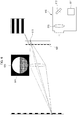
- FIG. 3 illustrates a patterned light projection apparatus according to an embodiment of the present disclosure.
- a patterned light projection apparatus 300 includes a light source 310, a grating 320, an aperture 330, and a lens 350, and the aperture 330 includes an opening 340.
- Light from the light source 310 passes through the grating 320, then enters the lens 350 through the opening 340 of the aperture 330, and is finally incident on a surface of an inspection object 380, which is an image-forming surface, for example, a surface of a substrate.
- a surface of an inspection object 380 which is an image-forming surface, for example, a surface of a substrate.
- Some of the light beams of the light from the light source are blocked by the shielding portions 324 of the grating 320, thereby forming shadows on the image-forming surface, that is, dark portions of the pattern and the light beams passing through the transmissive portions 322 of the grating 320 form bright portions of the pattern on the image-forming surface.
- the light source 310 may be a conventional light source utilized for projecting patterned light.
- the light source 310 may be a simple white light source, or a digital projector using an optical panel or the like as described above.
- the grating 320 is a striped grating having transmissive portions 322 and shielding portions 324.
- the transmissive portions 322 are opening portions of the grating, and the light from the light source is transmitted through the transmissive portions 322 and projected toward the object so as to be projected to the surface of the inspection object (image-forming surface).
- the shielding portions 324 block light from the light source, and shadows are generated in the regions on the object where light is blocked by the shielding portions 324.
- the grating has a form in which transmissive portions and shielding portions are alternately arranged. The respective widths of the transmissive portions and the shielding portions of the grating may vary depending on the pitch of the patterned light to be projected.
- the aperture 330 has an opening 340, and the light passing through the grating 320 passes through the opening 340 of the aperture 330, so that the light can be projected onto the object through the lens 350. Because the transmissive portions 322 and the shielding portions 324 of the grating alternate, the light passing through the transmissive portions 322 can pass through the opening 340 of the aperture 330. When the light is not transmitted by being blocked by the shielding portions 324, a shadow is also formed at a corresponding position in the opening 340 of the aperture 330 (B).
- a focused range that is, the depth of field may be adjusted through a method of adjusting the distances among the light source 310, the grating 320, the lens 350, and the image-forming plane 380 when the light passing through the lens 350 reaches the image-forming surface 380, a method of adjusting the size of the opening 340 of the aperture 330, or the like. Since the light from the light source 310 is partially blocked by the grating 320 to form a shadow of a striped pattern, when the respective components of the patterned light projection apparatus are adjusted so as to be accurately focused on the image-forming surface 380, an accurately striped pattern is formed.
- the shape of the opening of the aperture may vary. As illustrated in FIG. 3 , the opening may be a circular opening 340 similar to the shape of a general aperture. However, it is possible to use an opening 440 of an aperture 430, the outline of which has a sinusoidal wave curve shape that is symmetrical with respect to the vertical direction as illustrated in FIG. 4 . Specifically, when the opening of the aperture has a shape as illustrated in FIG. 4 , patterned light having the most ideal sinusoidal form may be projected. However, it is not always necessary to use an aperture in the form of a sinusoidal wave.
- patterned light projection apparatus of the present disclosure, it is possible to enhance the quality of a three-dimensional image by projecting patterned light in the form of an ideal sinusoidal wave even if only a simple striped grating is used.
- patterned light having a fine pitch and to minimize the size of the grating by fabricating the grating as an on-off type striped grating by processing the grating in the smallest processable fine unit.
- FIG. 5 is a view for explaining a distance relationship between an aperture and a grating in a patterned light projection apparatus according to an embodiment of the present disclosure.
- An ideal sinusoidal patterned light should have a maximum difference in contrast between the brightest portion and the darkest portion of the pattern formed on the image-forming surface by the patterned light. Further, the ideal sinusoidal pattern should be the same as or similar to a sinusoidal wave curve in the form of a change in the contrast of the patterned light between the brightest portion and the darkest portion.
- the light should not pass through the aperture at all when the light is blocked by the shadow of the shielding portions of the grating, and all the light passing through the transmissive portions of the grating should be able to pass through the opening of the aperture without loss.
- the vertical width of the shadows 528 formed by the shielding portions 524 of the grating 520 is larger than the height of the opening 540, that is, the vertical width at the position of the aperture 530 such that the shadows 528 cover the entire opening 540, as illustrated in FIG. 5 .
- the difference in brightness between the bright portions and the dark portions of the sinusoidal patterned light is maximized.
- the positional relationship as in FIG. 5 can be achieved by adjusting the size of the opening of the aperture and the size of the shielding portions/transmissive portions of the grating, or adjusting the distance between the grating and the aperture.
- the distance between the grating and the aperture is increased, the shadow of the shielding portions of the grating is increased.
- the distance between the grating and the aperture is decreased, the shadow of the shielding portions of the grating is decreased. Therefore, by adjusting the positional relationship between the grating and the aperture such that the shadow of the shielding portions covers the opening of the aperture, it is possible to project patterned light in which the difference in contrast between a bright portion and a dark portion is maximized through the patterned light projection apparatus according to the present disclosure.
- a patterned light projection apparatus in which light from a light source passes through a grating including shielding portions and transmissive portions and is defocused on an image-forming surface, thereby projecting patterned light in the form of a sinusoidal wave.
- a method of projecting patterned light using a digital projector of a digital light processing type using an LCD, an LCOS, or a DMD element instead of passing the light from the light source through a grating is also possible.
- a digital projector using a DMD element when a digital projector using a DMD element is used, light projected from a light source can be reflected on a chip including a micro-driving mirror so as to project a pattern or an image.
- the patterned light can be projected by projecting a striped image, rather than needing a grating as in the conventional method.
- projecting the patterned light in the form of a sinusoidal wave using the defocusing principle of the present disclosure can be similarly implemented in a patterned light projection apparatus using a digital projector.
- FIG. 6 illustrates a patterned light projection apparatus according to another embodiment of the present disclosure, which forms patterned light by projecting a pattern image through a digital projector.
- the patterned light projection apparatus of FIG. 6 includes a projector 610 configured to project patterned light in a digital light source processing method using a DMD element.
- the projector 610 includes a light source 611, a mirror 612, and a lens 613, and the mirror 612 may be a DMD element in which micro-mirrors are integrated.
- the DMD element By the control of the DMD element, it is possible to directly project a striped patterned light with an aperture in the form of passing through a grating even if a separate grating is not included.
Landscapes
- Physics & Mathematics (AREA)
- General Physics & Mathematics (AREA)
- Optics & Photonics (AREA)
- Engineering & Computer Science (AREA)
- Computer Vision & Pattern Recognition (AREA)
- Chemical & Material Sciences (AREA)
- Analytical Chemistry (AREA)
- Length Measuring Devices By Optical Means (AREA)
Claims (12)
- Strukturierte Lichtprojektionsvorrichtung umfassend:einen Projektor (610);eine Blende (630), durch die Licht von dem Projektor (610) fällt; undeine Linse, die auf einem optischen Pfad positioniert ist, so dass das durch die Blende (630) fallende Licht auf einer bestrahlten Oberfläche konvergiert,wobei der Projektor (610) konfiguriert ist, ein Bild mit einem Streifenmuster zu projizieren,dadurch gekennzeichnet, dass die Blende (630) positioniert ist, so dass eine senkrechte Breite eines dunklen Bereichs des Streifenmusters, das an einer Stelle der Blende (630) gebildet ist, gleich einer oder größer als eine senkrechte Breite einer Öffnung (640) der Blende (630) ist, undwobei ein auf der bestrahlten Oberfläche gebildetes Lichtmuster eine Sinusform hat.
- Strukturierte Lichtprojektionsvorrichtung nach Anspruch 1, wobei die Sinusform durch Ändern einer Größe der Öffnung (640) der Blende (630) anpassbar ist.
- Strukturierte Lichtprojektionsvorrichtung nach Anspruch 1, wobei die Sinusform durch Ändern eines Abstandes zwischen der Blende (630) und dem Projektor (610) anpassbar ist.
- Strukturierte Lichtprojektionsvorrichtung nach Anspruch 1, wobei die Öffnung (640) der Blende (630) eine kombinierte Form aufweist, die erhalten wird, indem Kurven so kombiniert werden, dass sie symmetrisch zu einander sind.
- Strukturierte Lichtprojektionsvorrichtung nach Anspruch 4, wobei die kombinierte Form eine runde Form oder eine elliptische Form ist.
- Strukturierte Lichtprojektionsvorrichtung nach Anspruch 1, wobei die Öffnung (640) der Blende (630) eine kombinierte Form (440) aufweist, die erhalten wird, indem zwei halbperiodische Sinuswellenformen (442, 444) so kombiniert werden, dass sie symmetrisch zu einander bezüglich einer zu dem Streifenmuster senkrechten Richtung sind.
- Strukturierte Lichtprojektionsvorrichtung nach Anspruch 1, wobei die Öffnung (640) der Blende (630) eine polygonale Form hat.
- Strukturierte Lichtprojektionsvorrichtung nach Anspruch 1, wobei eine Lichtquelle (611) des Projektors (610) eine von einer Lichtquelle eines digitalen Lichtverarbeitungsverfahrens unter Verwendung eines DMD-Elements, einer LED-Lichtquelle und einer LCD-Lichtquelle ist.
- Strukturierte Lichtprojektionsvorrichtung nach Anspruch 1, wobei der Projektor (610) ein digitales Lichtverarbeitungsverfahren verwendet, das Licht von einer Lichtquelle (611) zu einem DMD-Element einschließlich eines Mikro-Spiegels (612) reflektiert, um das Bild mit dem Streifenmuster zu projizieren.
- Vorrichtung zum Prüfen eines dreidimensionalen Substrats, umfassend einen Lichtprojektor und ein Messgerät, wobei der Lichtprojektor die strukturierte Lichtprojektionsvorrichtung nach Anspruch 1 beinhaltet.
- Verfahren zur strukturierten Lichtprojektion, das strukturiertes Licht an ein die strukturierte Lichtprojektionsvorrichtung nach Anspruch 1 verwendendes Objekt projiziert, umfassend:
Durchführen einer defokussierenden Projektion durch Defokussieren des von der Lichtprojektionsvorrichtung projizierten strukturierten Lichts und Projizieren des strukturierten Lichts in einer Sinusform zu dem Objekt. - Verfahren zur strukturierten Lichtprojektion nach Anspruch 11, ferner umfassend:Durchführen einer fokussierenden Projektion, vor der defokussierenden Projektion, durch Projizieren des strukturierten Lichts in der Sinusform derart, dass das von der Lichtprojektionsvorrichtung projizierte strukturierte Licht auf dem Objekt fokussiert wird,wobei die defokussierende Projektion ein Anpassen einer positionellen Beziehung zwischen dem Projektor (610) und der Blende (630) beinhaltet, um das strukturierte Licht in Sinusform nach der fokussierenden Projektion zu projizieren.
Priority Applications (1)
| Application Number | Priority Date | Filing Date | Title |
|---|---|---|---|
| EP21166839.7A EP3876017B1 (de) | 2016-03-04 | 2017-03-03 | Strukturierte lichtbestrahlungsvorrichtung und verfahren |
Applications Claiming Priority (2)
| Application Number | Priority Date | Filing Date | Title |
|---|---|---|---|
| KR1020160026310A KR102079181B1 (ko) | 2016-03-04 | 2016-03-04 | 패턴광 조사 장치 및 방법 |
| PCT/KR2017/002352 WO2017150948A1 (ko) | 2016-03-04 | 2017-03-03 | 패턴광 조사 장치 및 방법 |
Related Child Applications (2)
| Application Number | Title | Priority Date | Filing Date |
|---|---|---|---|
| EP21166839.7A Division EP3876017B1 (de) | 2016-03-04 | 2017-03-03 | Strukturierte lichtbestrahlungsvorrichtung und verfahren |
| EP21166839.7A Division-Into EP3876017B1 (de) | 2016-03-04 | 2017-03-03 | Strukturierte lichtbestrahlungsvorrichtung und verfahren |
Publications (3)
| Publication Number | Publication Date |
|---|---|
| EP3425437A1 EP3425437A1 (de) | 2019-01-09 |
| EP3425437A4 EP3425437A4 (de) | 2019-04-10 |
| EP3425437B1 true EP3425437B1 (de) | 2021-05-19 |
Family
ID=59744248
Family Applications (2)
| Application Number | Title | Priority Date | Filing Date |
|---|---|---|---|
| EP21166839.7A Active EP3876017B1 (de) | 2016-03-04 | 2017-03-03 | Strukturierte lichtbestrahlungsvorrichtung und verfahren |
| EP17760352.9A Active EP3425437B1 (de) | 2016-03-04 | 2017-03-03 | Strukturierte lichtbestrahlungsvorrichtung und verfahren |
Family Applications Before (1)
| Application Number | Title | Priority Date | Filing Date |
|---|---|---|---|
| EP21166839.7A Active EP3876017B1 (de) | 2016-03-04 | 2017-03-03 | Strukturierte lichtbestrahlungsvorrichtung und verfahren |
Country Status (5)
| Country | Link |
|---|---|
| US (1) | US11002534B2 (de) |
| EP (2) | EP3876017B1 (de) |
| KR (1) | KR102079181B1 (de) |
| CN (1) | CN108780208B (de) |
| WO (1) | WO2017150948A1 (de) |
Families Citing this family (13)
| Publication number | Priority date | Publication date | Assignee | Title |
|---|---|---|---|---|
| CN109471321A (zh) * | 2018-11-24 | 2019-03-15 | 深圳阜时科技有限公司 | 一种光源结构、光学投影模组、感测装置及设备 |
| JP7241611B2 (ja) * | 2019-06-06 | 2023-03-17 | 東京エレクトロン株式会社 | パターン測定装置、パターン測定装置における傾き算出方法およびパターン測定方法 |
| EP4488622A3 (de) * | 2019-06-28 | 2025-04-09 | Koh Young Technology Inc | Vorrichtung und verfahren zur bestimmung der dreidimensionalen form eines objektes |
| KR102306973B1 (ko) * | 2019-07-30 | 2021-09-30 | (주)칼리온 | 패턴 마스크를 이용한 3차원 스캐닝의 프로젝션 시스템 및 그 방법 |
| KR102248248B1 (ko) * | 2019-11-06 | 2021-05-04 | 주식회사 메디트 | 물체 표면의 3d 데이터를 획득하는 구조광 투영 광학 시스템 |
| CN111043989B (zh) * | 2019-12-16 | 2021-12-03 | 电子科技大学 | 一种基于液晶底片的正弦条纹场投射模块 |
| JP2021148531A (ja) * | 2020-03-18 | 2021-09-27 | 株式会社東芝 | 光学装置、情報処理方法、および、プログラム |
| KR20220157819A (ko) * | 2021-05-21 | 2022-11-29 | (주)테크윙 | 형상 측정장치 및 형상 측정방법 |
| KR102693010B1 (ko) | 2021-10-14 | 2024-08-07 | 울산과학기술원 | 최대 명암비 증강 영상 획득 장치, 방법, 컴퓨터 판독 가능한 기록 매체 및 컴퓨터 프로그램 |
| CN114721214B (zh) * | 2022-04-15 | 2023-04-25 | 电子科技大学 | 一种用于移动终端的微型正弦结构光投影系统 |
| KR102810984B1 (ko) * | 2022-11-18 | 2025-05-22 | (주)펨트론 | 리드탭의 검사 장치 및 검사 방법 |
| KR102810983B1 (ko) * | 2022-11-18 | 2025-05-22 | (주)펨트론 | 리드탭의 검사 장치 및 검사 방법 |
| CN119468931B (zh) * | 2024-11-14 | 2025-10-28 | 福州大学 | 一种基于交叉正弦复合条纹的远距离位移测量装置及其测量方法 |
Family Cites Families (42)
| Publication number | Priority date | Publication date | Assignee | Title |
|---|---|---|---|---|
| JPS4843376Y1 (de) * | 1969-12-13 | 1973-12-14 | ||
| US3802769A (en) * | 1972-08-28 | 1974-04-09 | Harris Intertype Corp | Method and apparatus for unaided stereo viewing |
| DE3248338A1 (de) * | 1982-12-28 | 1984-06-28 | Wolff Walsrode Ag, 3030 Walsrode | Verfahren zum verpacken von schlauchfoermigen gerafften nahrungsmittelhuellen |
| US4588276A (en) * | 1985-05-29 | 1986-05-13 | Nippon Seimitsu Kogyo Kabushiki Kaisha | Iris diaphragm device for a camera |
| US6603103B1 (en) * | 1998-07-08 | 2003-08-05 | Ppt Vision, Inc. | Circuit for machine-vision system |
| JP2947513B1 (ja) * | 1998-07-30 | 1999-09-13 | 株式会社ニデック | パターン検査装置 |
| US7317531B2 (en) * | 2002-12-05 | 2008-01-08 | Kla-Tencor Technologies Corporation | Apparatus and methods for detecting overlay errors using scatterometry |
| JP2002324743A (ja) * | 2001-04-24 | 2002-11-08 | Canon Inc | 露光方法及び装置 |
| US20030230015A1 (en) * | 2002-06-12 | 2003-12-18 | Mordeckai Mouyal | Louver card |
| CA2492687A1 (en) * | 2002-07-12 | 2004-01-22 | X3D Technologies Gmbh | Autostereoscopic projection system |
| GB2391635B (en) * | 2002-08-06 | 2005-07-13 | Wilkes Iris Ltd | Iris diaphragm |
| US7119911B2 (en) * | 2003-03-07 | 2006-10-10 | Lsa, Inc. | Moiré deflectometer including non-mechanical, transparent, spatial light modulators for demonstrating two-axis rulings |
| TW200510690A (en) | 2003-06-11 | 2005-03-16 | Solvision Inc | 3D and 2D measurement system and method with increased sensitivity and dynamic range |
| CA2475391C (en) | 2003-07-24 | 2011-10-25 | Inspeck Inc. | Optical 3d digitizer with enlarged non-ambiguity zone |
| US7361434B2 (en) * | 2003-09-30 | 2008-04-22 | Infineon Technologies Ag | Phase shift mask |
| JP4545155B2 (ja) | 2004-01-16 | 2010-09-15 | カール・ツァイス・エスエムティー・アーゲー | 光結像系の波面測定装置及び方法、及びマイクロリソグラフィ投影露光装置 |
| KR20060106256A (ko) * | 2005-04-07 | 2006-10-12 | 범광기전(주) | 영상획득장치 |
| WO2007018464A2 (en) * | 2005-08-08 | 2007-02-15 | Micronic Laser Systems Ab | Method and apparatus for projection printing |
| KR100663323B1 (ko) | 2005-11-07 | 2007-01-02 | (주) 인텍플러스 | 3차원 형상 측정 장치 및 그를 이용한 3차원 형상 측정방법 |
| US7804585B2 (en) * | 2006-01-08 | 2010-09-28 | Visiontools Bildanalyse Systeme Gmbh | Creation of a range image |
| JP2010507823A (ja) * | 2006-10-26 | 2010-03-11 | シーリアル テクノロジーズ ソシエテ アノニム | 小型のホログラフィック・ディスプレイ装置 |
| US8958137B2 (en) * | 2006-10-26 | 2015-02-17 | Seereal Technologies S.A. | Holographic display device with 2D encoding |
| TWI313361B (en) * | 2006-11-23 | 2009-08-11 | Delta Electronics Inc | Magnetic actuator structure and magnetic light-shielding apparatus |
| US8284392B2 (en) * | 2007-03-13 | 2012-10-09 | 3D-Shape Gmbh | Method and apparatus for the three-dimensional measurement of the shape and the local surface normal of preferably specular objects |
| KR101702887B1 (ko) * | 2007-04-18 | 2017-02-06 | 마이크로닉 마이데이타 에이비 | 무라 검출 및 계측을 위한 방법 및 장치 |
| ATE487111T1 (de) * | 2007-10-18 | 2010-11-15 | Nectar Imaging S R L | Vorrichtung zur tomografischen erfassung von objekten |
| KR100966311B1 (ko) * | 2008-02-20 | 2010-06-28 | 넥스타테크놀로지 주식회사 | Dmd를 이용한 모아레 장치 |
| KR101251372B1 (ko) * | 2008-10-13 | 2013-04-05 | 주식회사 고영테크놀러지 | 3차원형상 측정방법 |
| DE102010029091B4 (de) * | 2009-05-21 | 2015-08-20 | Koh Young Technology Inc. | Formmessgerät und -verfahren |
| US20110080471A1 (en) * | 2009-10-06 | 2011-04-07 | Iowa State University Research Foundation, Inc. | Hybrid method for 3D shape measurement |
| US9769455B2 (en) * | 2010-12-21 | 2017-09-19 | 3Shape A/S | 3D focus scanner with two cameras |
| WO2012099220A1 (ja) * | 2011-01-21 | 2012-07-26 | 兵庫県 | 3次元形状計測方法および3次元形状計測装置 |
| JP2014513869A (ja) * | 2011-04-22 | 2014-06-05 | マッパー・リソグラフィー・アイピー・ビー.ブイ. | ウェーハのようなターゲットを処理するためのリソグラフィシステム、及びウェーハのようなターゲットを処理するためのリソグラフィシステムを動作させる方法 |
| KR101423829B1 (ko) * | 2012-09-07 | 2014-07-25 | 주식회사 인스펙토 | 투영격자의 진폭을 적용한 3차원 형상 측정장치 및 방법 |
| CN103782129B (zh) | 2011-09-09 | 2016-09-14 | (株)茵斯派托 | 利用投影光栅振幅的三维形状测量装置及方法 |
| KR20130039130A (ko) * | 2011-10-11 | 2013-04-19 | (주)미토스 | 3차원 형상 스캐닝 장치 및 스캐닝 방법 |
| US8770780B1 (en) * | 2012-11-15 | 2014-07-08 | Tyson E. Jang | Display and illumination units used as part of a building |
| JP2014163812A (ja) * | 2013-02-26 | 2014-09-08 | Institute Of National Colleges Of Technology Japan | パターン投影方法、パターン投影装置及びこれを用いた三次元計測装置 |
| JP6238687B2 (ja) * | 2013-11-12 | 2017-11-29 | キヤノン株式会社 | マスクパターン作成方法、光学像の計算方法 |
| CN107193126B (zh) * | 2013-11-27 | 2020-06-05 | 奇跃公司 | 虚拟和增强现实系统与方法 |
| WO2015104239A2 (en) * | 2014-01-07 | 2015-07-16 | Seereal Technologies S.A. | Display device for holographic reconstruction |
| DE102015201561A1 (de) * | 2015-01-29 | 2016-08-04 | Rolls-Royce Deutschland Ltd & Co Kg | Messkopf einer endoskopischen Vorrichtung und Verfahren zur Inspektion und Messung eines Objektes |
-
2016
- 2016-03-04 KR KR1020160026310A patent/KR102079181B1/ko active Active
-
2017
- 2017-03-03 CN CN201780015242.XA patent/CN108780208B/zh active Active
- 2017-03-03 US US16/081,999 patent/US11002534B2/en active Active
- 2017-03-03 EP EP21166839.7A patent/EP3876017B1/de active Active
- 2017-03-03 WO PCT/KR2017/002352 patent/WO2017150948A1/ko not_active Ceased
- 2017-03-03 EP EP17760352.9A patent/EP3425437B1/de active Active
Also Published As
| Publication number | Publication date |
|---|---|
| CN108780208A (zh) | 2018-11-09 |
| EP3876017B1 (de) | 2022-04-20 |
| US11002534B2 (en) | 2021-05-11 |
| KR102079181B1 (ko) | 2020-02-19 |
| WO2017150948A1 (ko) | 2017-09-08 |
| EP3425437A4 (de) | 2019-04-10 |
| EP3425437A1 (de) | 2019-01-09 |
| EP3876017A1 (de) | 2021-09-08 |
| KR20170103418A (ko) | 2017-09-13 |
| US20200333135A1 (en) | 2020-10-22 |
| CN108780208B (zh) | 2021-01-15 |
Similar Documents
| Publication | Publication Date | Title |
|---|---|---|
| EP3425437B1 (de) | Strukturierte lichtbestrahlungsvorrichtung und verfahren | |
| JP4701948B2 (ja) | パタン光照射装置、3次元形状計測装置、及びパタン光照射方法 | |
| JP2009031150A (ja) | 三次元形状計測装置、三次元形状計測方法、三次元形状計測プログラム、および記録媒体 | |
| KR20120053710A (ko) | 표면 형상 측정 장치 | |
| JP2018515759A (ja) | オブジェクトの光学的3d測定のためのデバイス | |
| JP6522782B2 (ja) | 画像投射装置 | |
| EP2001226B1 (de) | Projektionsanzeige | |
| US9041907B2 (en) | Drawing device and drawing method | |
| JPWO2019159427A1 (ja) | カメラモジュール調整装置及びカメラモジュール調整方法 | |
| KR20160150283A (ko) | 광학 시스템 및 광학 기구의 이미지 보정 방법 | |
| US10841564B2 (en) | Three dimensional scan system that can increase the effective scan depth | |
| JP2005017336A (ja) | 投射面距離測定装置を有するプロジェクタ | |
| WO2017175303A1 (ja) | 標本形状測定方法及び標本形状測定装置 | |
| JP2016109823A (ja) | レンズ装置および投射表示装置 | |
| JP2005017350A (ja) | プロジェクタ | |
| US9110038B2 (en) | Asymmetric pattern projection apparatus | |
| JP5213761B2 (ja) | 照明光学系及びそれを有する画像投射装置 | |
| JP2021018081A (ja) | 撮像装置、計測装置、及び、計測方法 | |
| JP6770164B2 (ja) | 撮像装置 | |
| TWI671796B (zh) | 曝光裝置 | |
| US9632423B2 (en) | Illumination device, exposure apparatus, adjusting method, and method for manufacturing object | |
| JP2019060851A (ja) | レンズ特性測定装置及びレンズ特性測定装置の作動方法 | |
| JPWO2019088070A1 (ja) | 走査型眼底撮影装置 | |
| JP7072226B2 (ja) | プロジェクタおよびその使用方法 | |
| JP2008170209A (ja) | 形状測定方法 |
Legal Events
| Date | Code | Title | Description |
|---|---|---|---|
| STAA | Information on the status of an ep patent application or granted ep patent |
Free format text: STATUS: THE INTERNATIONAL PUBLICATION HAS BEEN MADE |
|
| PUAI | Public reference made under article 153(3) epc to a published international application that has entered the european phase |
Free format text: ORIGINAL CODE: 0009012 |
|
| STAA | Information on the status of an ep patent application or granted ep patent |
Free format text: STATUS: REQUEST FOR EXAMINATION WAS MADE |
|
| 17P | Request for examination filed |
Effective date: 20180928 |
|
| AK | Designated contracting states |
Kind code of ref document: A1 Designated state(s): AL AT BE BG CH CY CZ DE DK EE ES FI FR GB GR HR HU IE IS IT LI LT LU LV MC MK MT NL NO PL PT RO RS SE SI SK SM TR |
|
| AX | Request for extension of the european patent |
Extension state: BA ME |
|
| A4 | Supplementary search report drawn up and despatched |
Effective date: 20190308 |
|
| RIC1 | Information provided on ipc code assigned before grant |
Ipc: G02B 21/00 20060101ALI20190304BHEP Ipc: G02B 7/12 20060101AFI20190304BHEP Ipc: G02B 13/20 20060101ALI20190304BHEP Ipc: G03B 21/20 20060101ALI20190304BHEP Ipc: G01B 11/25 20060101ALI20190304BHEP |
|
| DAV | Request for validation of the european patent (deleted) | ||
| DAX | Request for extension of the european patent (deleted) | ||
| GRAP | Despatch of communication of intention to grant a patent |
Free format text: ORIGINAL CODE: EPIDOSNIGR1 |
|
| STAA | Information on the status of an ep patent application or granted ep patent |
Free format text: STATUS: GRANT OF PATENT IS INTENDED |
|
| INTG | Intention to grant announced |
Effective date: 20210120 |
|
| GRAS | Grant fee paid |
Free format text: ORIGINAL CODE: EPIDOSNIGR3 |
|
| GRAA | (expected) grant |
Free format text: ORIGINAL CODE: 0009210 |
|
| STAA | Information on the status of an ep patent application or granted ep patent |
Free format text: STATUS: THE PATENT HAS BEEN GRANTED |
|
| AK | Designated contracting states |
Kind code of ref document: B1 Designated state(s): AL AT BE BG CH CY CZ DE DK EE ES FI FR GB GR HR HU IE IS IT LI LT LU LV MC MK MT NL NO PL PT RO RS SE SI SK SM TR |
|
| REG | Reference to a national code |
Ref country code: GB Ref legal event code: FG4D |
|
| REG | Reference to a national code |
Ref country code: CH Ref legal event code: EP |
|
| REG | Reference to a national code |
Ref country code: DE Ref legal event code: R096 Ref document number: 602017038854 Country of ref document: DE |
|
| REG | Reference to a national code |
Ref country code: AT Ref legal event code: REF Ref document number: 1394554 Country of ref document: AT Kind code of ref document: T Effective date: 20210615 |
|
| REG | Reference to a national code |
Ref country code: IE Ref legal event code: FG4D |
|
| REG | Reference to a national code |
Ref country code: LT Ref legal event code: MG9D |
|
| REG | Reference to a national code |
Ref country code: AT Ref legal event code: MK05 Ref document number: 1394554 Country of ref document: AT Kind code of ref document: T Effective date: 20210519 |
|
| REG | Reference to a national code |
Ref country code: NL Ref legal event code: MP Effective date: 20210519 |
|
| PG25 | Lapsed in a contracting state [announced via postgrant information from national office to epo] |
Ref country code: BG Free format text: LAPSE BECAUSE OF FAILURE TO SUBMIT A TRANSLATION OF THE DESCRIPTION OR TO PAY THE FEE WITHIN THE PRESCRIBED TIME-LIMIT Effective date: 20210819 Ref country code: AT Free format text: LAPSE BECAUSE OF FAILURE TO SUBMIT A TRANSLATION OF THE DESCRIPTION OR TO PAY THE FEE WITHIN THE PRESCRIBED TIME-LIMIT Effective date: 20210519 Ref country code: HR Free format text: LAPSE BECAUSE OF FAILURE TO SUBMIT A TRANSLATION OF THE DESCRIPTION OR TO PAY THE FEE WITHIN THE PRESCRIBED TIME-LIMIT Effective date: 20210519 Ref country code: FI Free format text: LAPSE BECAUSE OF FAILURE TO SUBMIT A TRANSLATION OF THE DESCRIPTION OR TO PAY THE FEE WITHIN THE PRESCRIBED TIME-LIMIT Effective date: 20210519 Ref country code: LT Free format text: LAPSE BECAUSE OF FAILURE TO SUBMIT A TRANSLATION OF THE DESCRIPTION OR TO PAY THE FEE WITHIN THE PRESCRIBED TIME-LIMIT Effective date: 20210519 |
|
| PG25 | Lapsed in a contracting state [announced via postgrant information from national office to epo] |
Ref country code: SE Free format text: LAPSE BECAUSE OF FAILURE TO SUBMIT A TRANSLATION OF THE DESCRIPTION OR TO PAY THE FEE WITHIN THE PRESCRIBED TIME-LIMIT Effective date: 20210519 Ref country code: RS Free format text: LAPSE BECAUSE OF FAILURE TO SUBMIT A TRANSLATION OF THE DESCRIPTION OR TO PAY THE FEE WITHIN THE PRESCRIBED TIME-LIMIT Effective date: 20210519 Ref country code: NO Free format text: LAPSE BECAUSE OF FAILURE TO SUBMIT A TRANSLATION OF THE DESCRIPTION OR TO PAY THE FEE WITHIN THE PRESCRIBED TIME-LIMIT Effective date: 20210819 Ref country code: LV Free format text: LAPSE BECAUSE OF FAILURE TO SUBMIT A TRANSLATION OF THE DESCRIPTION OR TO PAY THE FEE WITHIN THE PRESCRIBED TIME-LIMIT Effective date: 20210519 Ref country code: PL Free format text: LAPSE BECAUSE OF FAILURE TO SUBMIT A TRANSLATION OF THE DESCRIPTION OR TO PAY THE FEE WITHIN THE PRESCRIBED TIME-LIMIT Effective date: 20210519 Ref country code: PT Free format text: LAPSE BECAUSE OF FAILURE TO SUBMIT A TRANSLATION OF THE DESCRIPTION OR TO PAY THE FEE WITHIN THE PRESCRIBED TIME-LIMIT Effective date: 20210920 Ref country code: IS Free format text: LAPSE BECAUSE OF FAILURE TO SUBMIT A TRANSLATION OF THE DESCRIPTION OR TO PAY THE FEE WITHIN THE PRESCRIBED TIME-LIMIT Effective date: 20210919 Ref country code: GR Free format text: LAPSE BECAUSE OF FAILURE TO SUBMIT A TRANSLATION OF THE DESCRIPTION OR TO PAY THE FEE WITHIN THE PRESCRIBED TIME-LIMIT Effective date: 20210820 |
|
| PG25 | Lapsed in a contracting state [announced via postgrant information from national office to epo] |
Ref country code: NL Free format text: LAPSE BECAUSE OF FAILURE TO SUBMIT A TRANSLATION OF THE DESCRIPTION OR TO PAY THE FEE WITHIN THE PRESCRIBED TIME-LIMIT Effective date: 20210519 |
|
| PG25 | Lapsed in a contracting state [announced via postgrant information from national office to epo] |
Ref country code: RO Free format text: LAPSE BECAUSE OF FAILURE TO SUBMIT A TRANSLATION OF THE DESCRIPTION OR TO PAY THE FEE WITHIN THE PRESCRIBED TIME-LIMIT Effective date: 20210519 Ref country code: ES Free format text: LAPSE BECAUSE OF FAILURE TO SUBMIT A TRANSLATION OF THE DESCRIPTION OR TO PAY THE FEE WITHIN THE PRESCRIBED TIME-LIMIT Effective date: 20210519 Ref country code: EE Free format text: LAPSE BECAUSE OF FAILURE TO SUBMIT A TRANSLATION OF THE DESCRIPTION OR TO PAY THE FEE WITHIN THE PRESCRIBED TIME-LIMIT Effective date: 20210519 Ref country code: CZ Free format text: LAPSE BECAUSE OF FAILURE TO SUBMIT A TRANSLATION OF THE DESCRIPTION OR TO PAY THE FEE WITHIN THE PRESCRIBED TIME-LIMIT Effective date: 20210519 Ref country code: DK Free format text: LAPSE BECAUSE OF FAILURE TO SUBMIT A TRANSLATION OF THE DESCRIPTION OR TO PAY THE FEE WITHIN THE PRESCRIBED TIME-LIMIT Effective date: 20210519 Ref country code: SK Free format text: LAPSE BECAUSE OF FAILURE TO SUBMIT A TRANSLATION OF THE DESCRIPTION OR TO PAY THE FEE WITHIN THE PRESCRIBED TIME-LIMIT Effective date: 20210519 Ref country code: SM Free format text: LAPSE BECAUSE OF FAILURE TO SUBMIT A TRANSLATION OF THE DESCRIPTION OR TO PAY THE FEE WITHIN THE PRESCRIBED TIME-LIMIT Effective date: 20210519 |
|
| REG | Reference to a national code |
Ref country code: DE Ref legal event code: R097 Ref document number: 602017038854 Country of ref document: DE |
|
| PLBE | No opposition filed within time limit |
Free format text: ORIGINAL CODE: 0009261 |
|
| STAA | Information on the status of an ep patent application or granted ep patent |
Free format text: STATUS: NO OPPOSITION FILED WITHIN TIME LIMIT |
|
| 26N | No opposition filed |
Effective date: 20220222 |
|
| PG25 | Lapsed in a contracting state [announced via postgrant information from national office to epo] |
Ref country code: IS Free format text: LAPSE BECAUSE OF FAILURE TO SUBMIT A TRANSLATION OF THE DESCRIPTION OR TO PAY THE FEE WITHIN THE PRESCRIBED TIME-LIMIT Effective date: 20210919 Ref country code: AL Free format text: LAPSE BECAUSE OF FAILURE TO SUBMIT A TRANSLATION OF THE DESCRIPTION OR TO PAY THE FEE WITHIN THE PRESCRIBED TIME-LIMIT Effective date: 20210519 |
|
| PG25 | Lapsed in a contracting state [announced via postgrant information from national office to epo] |
Ref country code: IT Free format text: LAPSE BECAUSE OF FAILURE TO SUBMIT A TRANSLATION OF THE DESCRIPTION OR TO PAY THE FEE WITHIN THE PRESCRIBED TIME-LIMIT Effective date: 20210519 |
|
| PG25 | Lapsed in a contracting state [announced via postgrant information from national office to epo] |
Ref country code: MC Free format text: LAPSE BECAUSE OF FAILURE TO SUBMIT A TRANSLATION OF THE DESCRIPTION OR TO PAY THE FEE WITHIN THE PRESCRIBED TIME-LIMIT Effective date: 20210519 |
|
| REG | Reference to a national code |
Ref country code: CH Ref legal event code: PL |
|
| GBPC | Gb: european patent ceased through non-payment of renewal fee |
Effective date: 20220303 |
|
| REG | Reference to a national code |
Ref country code: BE Ref legal event code: MM Effective date: 20220331 |
|
| PG25 | Lapsed in a contracting state [announced via postgrant information from national office to epo] |
Ref country code: LU Free format text: LAPSE BECAUSE OF NON-PAYMENT OF DUE FEES Effective date: 20220303 Ref country code: LI Free format text: LAPSE BECAUSE OF NON-PAYMENT OF DUE FEES Effective date: 20220331 Ref country code: IE Free format text: LAPSE BECAUSE OF NON-PAYMENT OF DUE FEES Effective date: 20220303 Ref country code: GB Free format text: LAPSE BECAUSE OF NON-PAYMENT OF DUE FEES Effective date: 20220303 Ref country code: FR Free format text: LAPSE BECAUSE OF NON-PAYMENT OF DUE FEES Effective date: 20220331 Ref country code: CH Free format text: LAPSE BECAUSE OF NON-PAYMENT OF DUE FEES Effective date: 20220331 |
|
| PG25 | Lapsed in a contracting state [announced via postgrant information from national office to epo] |
Ref country code: BE Free format text: LAPSE BECAUSE OF NON-PAYMENT OF DUE FEES Effective date: 20220331 |
|
| PG25 | Lapsed in a contracting state [announced via postgrant information from national office to epo] |
Ref country code: HU Free format text: LAPSE BECAUSE OF FAILURE TO SUBMIT A TRANSLATION OF THE DESCRIPTION OR TO PAY THE FEE WITHIN THE PRESCRIBED TIME-LIMIT; INVALID AB INITIO Effective date: 20170303 |
|
| PG25 | Lapsed in a contracting state [announced via postgrant information from national office to epo] |
Ref country code: MK Free format text: LAPSE BECAUSE OF FAILURE TO SUBMIT A TRANSLATION OF THE DESCRIPTION OR TO PAY THE FEE WITHIN THE PRESCRIBED TIME-LIMIT Effective date: 20210519 Ref country code: CY Free format text: LAPSE BECAUSE OF FAILURE TO SUBMIT A TRANSLATION OF THE DESCRIPTION OR TO PAY THE FEE WITHIN THE PRESCRIBED TIME-LIMIT Effective date: 20210519 |
|
| PG25 | Lapsed in a contracting state [announced via postgrant information from national office to epo] |
Ref country code: TR Free format text: LAPSE BECAUSE OF FAILURE TO SUBMIT A TRANSLATION OF THE DESCRIPTION OR TO PAY THE FEE WITHIN THE PRESCRIBED TIME-LIMIT Effective date: 20210519 |
|
| PG25 | Lapsed in a contracting state [announced via postgrant information from national office to epo] |
Ref country code: MT Free format text: LAPSE BECAUSE OF FAILURE TO SUBMIT A TRANSLATION OF THE DESCRIPTION OR TO PAY THE FEE WITHIN THE PRESCRIBED TIME-LIMIT Effective date: 20210519 |
|
| PGFP | Annual fee paid to national office [announced via postgrant information from national office to epo] |
Ref country code: DE Payment date: 20250204 Year of fee payment: 9 |